1
Systems Management
Professional User's Manual
Course:
Masters in Computer Science (Conversion) 2013-14, University College Dublin
Module:
Systems Management (delivered at the Institute of Public Administration)
Assignment Title:
Module Assignment 2014 Parts A & B - Professional User's Manual
Submitted by:
Garrett Coleman, Student No. 96344598
Lecturer:
Mr. Tom Brett
Submission Date:
4th August 2014
Word Count Excluding Appendices:
18,404
SYSTEMS MANAGEMENT ASSIGNMENT – PROFESSIONAL USER’S MANUAL
July 30, 2014
Table of Contents
1.
Introduction...............................................................................................................................5
Part A.....................................................................................................................................................6
2.
Part A - Task A1 ........................................................................................................................6
2.1
Preamble ................................................................................................................................6
2.1.1
High Touch Installation.................................................................................................6
2.1.2
Zero Touch Installation .................................................................................................6
2.1.3
Lite Touch Installation (LTI) ..........................................................................................6
2.2
System Requirements ...........................................................................................................7
2.3
Procedure...............................................................................................................................8
2.3.1
Step 1 - Installation of the Windows Automated Installation Kit (Windows AIK) ......8
2.3.2
Step 2 - Building an Answer File .................................................................................13
2.3.3
Step 3 - Building a Reference Installation ..................................................................22
2.3.4
Step 4 - Creating Bootable Windows PE Media ..........................................................23
2.3.5
Step 5 - Capturing the Installation onto a Network Share........................................26
2.3.6
Step 6 - Deploying from a Network Share .................................................................29
3.
Part A - Task A2 ......................................................................................................................32
3.1
Preamble ..............................................................................................................................32
3.1.1
How BitLocker Drive Encryption Works ......................................................................32
3.1.2
TPM Definition .............................................................................................................33
3.2
System Requirements .........................................................................................................33
3.2.1
Windows Versions .......................................................................................................33
3.2.2
System Configuration..................................................................................................34
3.3
Procedure.............................................................................................................................34
3.3.1
BitLocker Drive Encryption on OS drive of computer with TPM ...............................34
3.3.2
BitLocker Drive Encryption on OS drive of computer with no TPM..........................36
Part B ...................................................................................................................................................50
4.
Part B - Task A .........................................................................................................................50
4.1
Preamble ..............................................................................................................................50
4.2
System Requirements .........................................................................................................51
4.3
Procedure.............................................................................................................................52
4.3.1
Subtask 1 - Create Three Server Virtual Machines ...................................................52
4.3.2
Subtask 2 - Create Client Machine with Windows 7.................................................61
4.3.3
Subtask 3 - Computer Names....................................................................................65
4.3.4
Subtask 4 - Assign Static IP Addresses to all Machines...........................................71
5.
Part B - Task B .........................................................................................................................77
5.1
Preamble ..............................................................................................................................77
5.2
Procedure.............................................................................................................................78
5.2.1
Subtask 1 - Setup Server1 as a Domain Controller of the Tree ...............................78
5.2.2
Subtask 2 - Setup Client1 as a Workstation Member of the Tree ............................89
5.2.3
Subtask 3 - Setup Server2 as a Second Domain Controller of the Tree ..................92
5.2.4
Subtask 4 - Setup MS-Core as a Member Server of the Tree ....................................98
GARRETT COLEMAN . STUDENT NO.: 96344598
2
SYSTEMS MANAGEMENT ASSIGNMENT – PROFESSIONAL USER’S MANUAL
5.2.5
6.
July 30, 2014
Confirm Configurations ..............................................................................................99
Part B - Task C ...................................................................................................................... 101
6.1
Preamble ........................................................................................................................... 101
6.2
System Requirements ...................................................................................................... 102
6.2.1 - Disk Mirroring............................................................................................................... 102
6.2.2 - Spanned Volume........................................................................................................... 102
6.3
Procedure.......................................................................................................................... 102
6.3.1
Subtask 1 - Install 2 Additional Hard Disks on Server 1........................................ 102
6.3.2
Subtask 2 - Use an Additional Hard Disk to Mirror the OS Disk ........................... 106
6.3.3
Subtask 3 - Create a Spanned Volume to Use Remaining Free Disk Space.......... 108
7.
Part B - Task D...................................................................................................................... 113
7.1
Preamble ........................................................................................................................... 113
7.2
Procedure.......................................................................................................................... 114
7.2.1
Subtask 1 - Create Organisational Unit Structure .................................................. 114
7.2.2
Subtask 2 - Creating Users using a TUI Environment ............................................ 116
7.2.3
Subtask 3 - Create Users.......................................................................................... 118
7.2.3
Subtask 3 - Set Logon Hours for Users ................................................................... 122
8.
Part B - Task E....................................................................................................................... 124
8.1
Preamble ........................................................................................................................... 124
8.2
Procedure.......................................................................................................................... 125
8.2.1
Subtask 1 - Group Users in each OU ....................................................................... 125
8.2.2
Subtask 2 - Prevent users in Marketing OU from being able to see IT OU .......... 154
8.2.3
Subtask 3 - Folder Redirection Group Policy Object (GPO).................................... 159
8.2.4
Subtask 4 - Prohibit Control Panel Access Group Policy Object ........................... 170
8.2.5
Subtask 5 - MSI File Publishing Group Policy Object ............................................. 179
9.
Part B - Task F....................................................................................................................... 186
9.1
Preamble ........................................................................................................................... 186
9.2
Procedure.......................................................................................................................... 186
9.2.1
Subtask 1 - Set Up MS-Core Server as a Files Server .............................................. 186
9.2.2
Subtask 2 - Configure MS-Core for Windows Remote Administration.................. 188
9.2.3
Subtask 3 - Access MS-Core from Client2 Using Remote Desktop ....................... 189
10.
Part B - Task G ...................................................................................................................... 193
10.1
Preamble ........................................................................................................................... 193
10.2
Procedure.......................................................................................................................... 193
10.2.1
Subtask 1 - Install DHCP on Server 2 ...................................................................... 193
10.2.2
Subtask 2 - Configure Client2 to obtain address & TCP/IP settings from DHCP . 202
10.2.3
Subtask 3 - Disable DHCP Services & Confirm Address Assigned to Client2 ...... 204
11.
Part B - Task H ...................................................................................................................... 208
11.1
Preamble ........................................................................................................................... 208
11.2
Procedure.......................................................................................................................... 208
11.2.1
Subtask 1 - Decommissioning Server2 from the Active Directory ........................ 208
11.2.2
Subtask 2 - Deleting Domain Controller using dcpromo if Server is Bootable .... 209
GARRETT COLEMAN . STUDENT NO.: 96344598
3
SYSTEMS MANAGEMENT ASSIGNMENT – PROFESSIONAL USER’S MANUAL
July 30, 2014
Appendix A - References................................................................................................................. 215
Appendix B - Assignment Details - Part A ..................................................................................... 216
Appendix C - Assignment Details - Part B ..................................................................................... 218
Appendix D - Creation of a Virtual Machine & Installation of Windows 7 Pro. OS ..................... 221
GARRETT COLEMAN . STUDENT NO.: 96344598
4
SYSTEMS MANAGEMENT ASSIGNMENT – PROFESSIONAL USER’S MANUAL
1.
July 30, 2014
Introduction
This document is a professional user's manual that follows a series of practical tasks set by the
Institute of Public Administration as the module assignment associated with the Systems
Management module of the Masters in Computer Science (Conversion) 2013-2014 at University
College Dublin.
The full texts of the module assignment are provided in Appendices B and C hereunder.
The required tasks are broken into two parts, A and B. Part A relates to network-based
installation of Windows operating systems and the enforcement of full drive encryption, while
part B relates to the setting up of server operating systems and the configuring of servers,
networks and Microsoft's Active Directory Domain Service.
This user manual explains the reasons why the required tasks would be carried out in an
enterprise environment, highlighting the benefits and drawbacks of approaches where
applicable, and then describes in writing, with the aid of annotated screenshots, the steps that
need to be taken to complete each of the relevant tasks.
The manual has been written for a trainee IT administrator, with the aim of instructing said
trainee as to how the relevant tasks would be carried out, and references are provided where
pertinent, to facilitate further learning.
The manual is broken up into parts A and B, with sub-sections relating to each task required to
be carried out, as listed in the table of contents above.
The instructions for each task are provided at the beginning of each sub-section in italics, and
the description of each task generally takes the form of a preamble describing the reasons for
carrying out said task along with any related advantages and/or disadvantages, followed by an
overview of any system requirements that may apply, and finally a step-by-step description of
how the task is carried out, employing screenshots as a visual aid. Screenshots are located
immediately after the text to which they relate.
References have been provided in adherence with APA formatting, however in addition to
references being listed in Appendix A, as per the recommendations of the APA guidelines,
references are also included as footnotes at the bottom of the page they appear on. The user
manual has entailed a lengthy document and it was felt that same page referencing would be of
assistance to the reader.
GARRETT COLEMAN . STUDENT NO.: 96344598
5
SYSTEMS MANAGEMENT ASSIGNMENT – PROFESSIONAL USER’S MANUAL
July 30, 2014
Part A
2.
Part A - Task A1
Using Virtual Machines to mimic the use of Physical Machines, document and Install Microsoft
Windows 7 using the Lite Touch Installation (LTI) method.
2.1
Preamble
Microsoft provide several different methods for the installation of windows 7, ranging from
manual methods such as inserting a DVD, to completely automated methods that can be
effected over a network or via the cloud. These fully automated methods are known as "nontouch" installations.
Installation methods can be categorised as follows:
High Touch Installation (HTI)
Lite Touch Installation (LTI)
Zero Touch Installation (ZTI)
2.1.1
High Touch Installation
The High Touch Installation requires the manual configuration of each system, using an
installation DVD or standard image (ISO file) to manually install the operating system
individually on every computer. When employing the High Touch Installation on a larger
environment, a single installation is carried out, and an image of the installation is created
using the ImageX tool that is included as part of the Windows Automated Installation Kit (AIK).
2.1.2
Zero Touch Installation
The Zero Touch Installation is a fully automated means of installing windows that is typically
employed in larger environments with 500 or more computers. It is considered to require a
high level of system administration competency, as well as a significant budget compared to
other installation methods. This method uses System Center Configuration Manager to deploy
and update servers, client computers and devices on a network.
2.1.3
Lite Touch Installation (LTI)
The Lite Touch Installation approach that is described hereunder requires some human
interaction in the initial stages of the installation but is thereafter automated. The approach
works well in environments with more than 150 computers.
The Lite Touch Installation method described below describes the deployment of Windows 7
using the Windows Automated Installation Kit (Windows AIK).
GARRETT COLEMAN . STUDENT NO.: 96344598
6
SYSTEMS MANAGEMENT ASSIGNMENT – PROFESSIONAL USER’S MANUAL
July 30, 2014
The procedure follows the step by step instructions provided by Microsoft for how to configure
and deploy a Windows image on Microsoft TechNet, the Microsoft web portal and web service
for IT professionals1.
A six step process describes the creation of a valid answer file that is used to install windows 7,
the preparation of a bootable Windows Preinstallation Environment (Windows PE), and the
deployment of a custom Windows image from a network share. The five steps are as follows:
1. Installation of the Windows Automated Installation Kit
2. Building an Answer File
3. Building a Reference Installation
4. Creating Bootable Windows PE Media
5. Capturing the Installation onto a Network Share
6. Deploying from a Network Share
2.2
System Requirements
A Windows 7 product DVD disc or Windows 7 .iso file as is described in this manual.
A Windows AIK DVD disc or Windows AIK .iso file as is described in this manual, which is
available at the download center on the Microsoft website 2.
A technician computer
A virtual machine hereafter referred to as the technician computer is created with
Windows 7 installed on it.
The creation of virtual machines, using VMWare Workstation 9 is outside the scope of
this user manual, however for reference purposes, the steps involved in this process,
as described in a previously prepared user's manual are included as Appendix D.
This is the computer on which we will install the Windows Automated Installation Kit
(Windows AIK).
A reference computer
A virtual machine hereafter referred to as the reference computer is created with no
operating system installed on it.
This is the computer where we will install a customized installation using the
Windows 7 .iso file and an answer file.
Once installed, we will capture and store an image of the installation on a network
share.
Network connectivity between the technician and reference computers.
1
http://technet.microsoft.com/en-us/library/dd349348(v=ws.10).aspx. Accessed July 1, 2014.
2
http://go.microsoft.com/fwlink/?LinkId=136976. Accessed July 1, 2014.
GARRETT COLEMAN . STUDENT NO.: 96344598
7
SYSTEMS MANAGEMENT ASSIGNMENT – PROFESSIONAL USER’S MANUAL
July 30, 2014
2.3
Procedure
2.3.1
Step 1 - Installation of the Windows Automated Installation Kit (Windows AIK)
Firstly, using our technician computer, we download the Windows AIK from Microsoft’s
website3.
After the download has completed we then install the AIK download. This can be done by
burning the downloaded *.iso image file to a DVD disk and running it. As an alternative, in
order to expand our knowledge, we will download a program that will emulate the image file
onto a virtual drive, we will use Virtual CloneDrive, provided by SlySoft4.
3
4
http://go.microsoft.com/fwlink/?LinkId=136976. Accessed July 1, 2014.
http://www.slysoft.com/en/download.html. Accessed July 1, 2014.
GARRETT COLEMAN . STUDENT NO.: 96344598
8
SYSTEMS MANAGEMENT ASSIGNMENT – PROFESSIONAL USER’S MANUAL
July 30, 2014
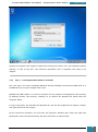
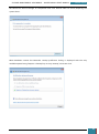
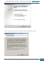
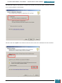
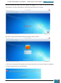
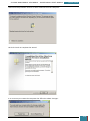
Once Virtual CloneDrive has been downloaded we launch the installation using the *.exe file
that we have downloaded, following the steps on the installation wizard.
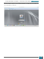
Once the installation is complete, the installation window will close and we launch the Virtual
Clone Drive software from the desktop.
GARRETT COLEMAN . STUDENT NO.: 96344598
9
SYSTEMS MANAGEMENT ASSIGNMENT – PROFESSIONAL USER’S MANUAL
July 30, 2014
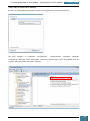
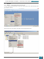
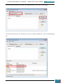
A selection pane is opened prompting us as to how many drives we wish to create - we select
one virtual drive for the installation of the Windows AIK
Our next step is to mount the image (*.iso) file that we downloaded to the drive we have just
created.
We click on the icon in the bottom right of the desktop highlighted in the screenshot below to
open a pop-up menu, where we right click on the larger highlighted area.
On the resultant menu, we hover over the virtual drive and select "mount" from the pop-out
menu.
GARRETT COLEMAN . STUDENT NO.: 96344598
10
SYSTEMS MANAGEMENT ASSIGNMENT – PROFESSIONAL USER’S MANUAL
July 30, 2014
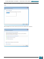
A new window is opened and we select the Windows AIK image file from where we have saved it
on the desktop to be mounted to the virtual drive.
Once mounted to the virtual drive, a new window opens emulating that a disk has just been
inserted, and we select to run the StartCD.exe.
GARRETT COLEMAN . STUDENT NO.: 96344598
11
SYSTEMS MANAGEMENT ASSIGNMENT – PROFESSIONAL USER’S MANUAL
July 30, 2014
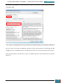
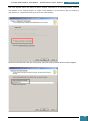
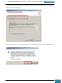
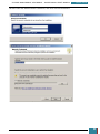
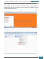
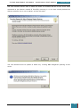
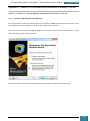
A new window will appear and show the options for installation. We select ‘Windows AIK Setup’
and follow the instructions on the setup wizard for installation.
Once complete, we close the installer, highlighted below.
GARRETT COLEMAN . STUDENT NO.: 96344598
12
SYSTEMS MANAGEMENT ASSIGNMENT – PROFESSIONAL USER’S MANUAL
2.3.2
July 30, 2014
Step 2 - Building an Answer File
Now that the Windows AIK is installed on out technician computer, we can build an answer file.
An answer file is used to configure Windows settings during installation and it contains all of
the settings that are needed for an unattended installation so that during installation a user is
not prompted with user interface pages.
Hereunder we describe the process for creating an answer file using Windows System Image
Manager (Windows SIM). Windows SIM is a utility for creating and modifying unattended answer
files and configuration sets.
We will copy a Windows image file (.wim) to our technician computer, and then create a simple
answer file that includes basic Windows Setup configuration and minimum Windows Welcome
customizations.
Having copied our Windows 7 .iso file onto a blank DVD, on our technician computer, we insert
the DVD.
We open the \Sources directory on our Windows 7 .iso file and copy the Install.wim file located
there to the desktop of the technician computer.
GARRETT COLEMAN . STUDENT NO.: 96344598
13
SYSTEMS MANAGEMENT ASSIGNMENT – PROFESSIONAL USER’S MANUAL
July 30, 2014
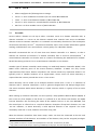
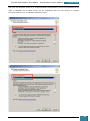
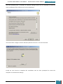
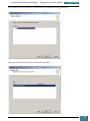
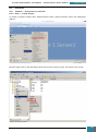
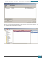
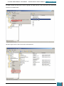
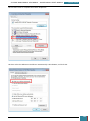
We then open Windows SIM by clicking click Start, All Programs, Microsoft Windows AIK, and
then Windows System Image Manager.
On the Windows SIM file menu we click Select Windows Image.
In the Select a Windows Image dialog box, we navigate to the desktop where we saved
Install.wim above, and then click Open.
GARRETT COLEMAN . STUDENT NO.: 96344598
14
SYSTEMS MANAGEMENT ASSIGNMENT – PROFESSIONAL USER’S MANUAL
July 30, 2014
We are then prompted to select an image, we choose the Windows image that we want to
install, and then click OK.
At the prompt to create a catalog file we click Yes to generate the file.
We click File, New Answer File, and an empty answer file appears in the Answer File pane.
GARRETT COLEMAN . STUDENT NO.: 96344598
15
SYSTEMS MANAGEMENT ASSIGNMENT – PROFESSIONAL USER’S MANUAL
July 30, 2014
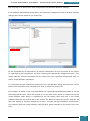
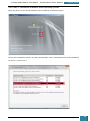
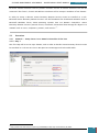
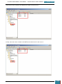
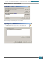
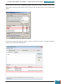
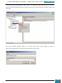
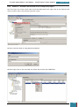
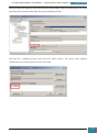
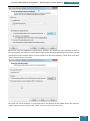
Our next step is to define basic disk configuration and Windows Welcome settings.
In the Windows SIM Windows Image pane, we expand the Components node to display available
settings that can be copied to our answer file.
On the expanded list of components, we add the components we wish to include in our answer
by right-clicking the component, and then selecting the appropriate configuration pass. This
action adds the selected component to our answer file in the specified configuration pass, or
phase, of the Windows installation.
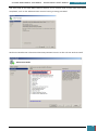
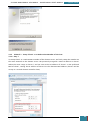
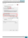
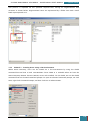
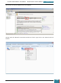
It is important that we expand the component list in the Windows Image pane until we see the
lowest child node that is the component we wish to add to our answer file.
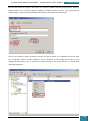
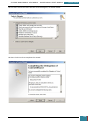
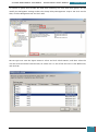
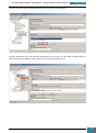
For example, as shown in the screenshot below, we expand Microsoft-Windows-Setup to see the
DiskConfiguration node, which we expand to see the disk node, which we expand to see the
create partition node, which is expanded to see the lowest child node that is the create
partition node that we wish to add to our answer file. When we right click on this node we are
given the option to add this component to Pass 1 windows PE (pre-installation environment).
This shortcut adds the create partition setting and all parent settings to our answer file in one
step.
GARRETT COLEMAN . STUDENT NO.: 96344598
16
SYSTEMS MANAGEMENT ASSIGNMENT – PROFESSIONAL USER’S MANUAL
July 30, 2014
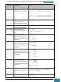
Following the step by step instructions provided by Microsoft we add the components in the
table below, this manual describes the creation of a two-partition configuration, therefore two
create partition components and two modify partition components are added to the windowsPE
configuration pass:
Component
Configuration Pass
Microsoft-Windows-Deployment\Reseal
oobeSystem
Microsoft-Windows-International-Core-WinPE\SetupUILanguage
windowsPE
Microsoft-WindowsSetup\DiskConfiguration\Disk\CreatePartitions\CreatePartition
Microsoft-WindowsSetup\DiskConfiguration\Disk\ModifyPartitions\ModifyPartition
Microsoft-WindowsSetup\DiskConfiguration\Disk\CreatePartitions\CreatePartition
Microsoft-WindowsSetup\DiskConfiguration\Disk\ModifyPartitions\ModifyPartition
windowsPE
windowsPE
windowsPE
windowsPE
Microsoft-Windows-Setup\ImageInstall\OSImage\InstallTo
windowsPE
Microsoft-Windows-Setup\UserData
windowsPE
Microsoft-Windows-Shell-Setup\OOBE
oobeSystem
GARRETT COLEMAN . STUDENT NO.: 96344598
17
SYSTEMS MANAGEMENT ASSIGNMENT – PROFESSIONAL USER’S MANUAL
July 30, 2014
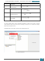
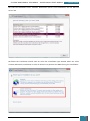
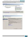
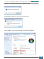
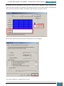
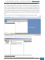
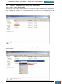
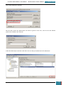
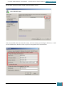
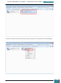
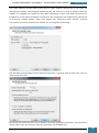
All of the settings we added will now be present in the Windows SIM Answer File pane, as
shown below.
When we click on any lowest child node of a component the properties and settings for that
node are displayed in the right-hand properties pane, and it is in the settings variables that
enter specific values as listed in the table below:
GARRETT COLEMAN . STUDENT NO.: 96344598
18
SYSTEMS MANAGEMENT ASSIGNMENT – PROFESSIONAL USER’S MANUAL
Configuration
July 30, 2014
Component
Value
Microsoft-Windows-
InputLocale = <Input Locale>For example, en-US
Pass
1 WindowsPE
International-Core-WinPE
SystemLocale = <System Locale>For example, enUS
UILanguage = <UI Language> For example, en-US
UserLocale = <User Locale> For example, en-US
1 WindowsPE
Microsoft-Windows-
UILanguage = <UI Language> For example, en-US
International-CoreWinPE\SetupUILanguage
1 WindowsPE
Microsoft-Windows-
WillShowUI = OnError
Setup\DiskConfiguration
1 WindowsPE
Microsoft-WindowsSetup\DiskConfiguration\
Disk
1 WindowsPE
Microsoft-WindowsSetup\DiskConfiguration\
Disk\CreatePartitions\Crea
tePartition
1 WindowsPE
Microsoft-WindowsSetup\DiskConfiguration\
Disk\CreatePartitions\Crea
tePartition
1 WindowsPE
Microsoft-WindowsSetup\DiskConfiguration\
Disk\ModifyPartitions\Mod
ifyPartition
DiskID = 0
WillWipeDisk = true
Order = 1
Size = 300
Type = Primary
Extend = true
Order = 2
Type = Primary
Active = true
Format = NTFS
Label = System
Order = 1
PartitionID = 1
1 WindowsPE
Microsoft-WindowsSetup\DiskConfiguration\
Disk\ModifyPartitions\Mod
ifyPartition
1 WindowsPE
Microsoft-WindowsSetup\ImageInstall\OSIma
ge
1 WindowsPE
Microsoft-WindowsSetup\ImageInstall\OSIma
Format = NTFS
Label = Windows
Order = 2
PartitionID = 2
InstallToAvailablePartition= false
WillShowUI = OnError
DiskID = 0
PartitionID = 2
GARRETT COLEMAN . STUDENT NO.: 96344598
19
SYSTEMS MANAGEMENT ASSIGNMENT – PROFESSIONAL USER’S MANUAL
July 30, 2014
ge\InstallTo
1 WindowsPE
Microsoft-Windows-
AcceptEula = true
Setup\UserData
1 WindowsPE
Microsoft-WindowsSetup\UserData\ProductKe
y
7 oobeSystem
Microsoft-WindowsDeployment\Reseal
7 oobeSystem
Microsoft-Windows-ShellSetup\OOBE
Key = <product key>
WillShowUI = OnError
ForceShutdownNow = false
Mode = Audit
HideEULAPage = true
ProtectYourPC = 3
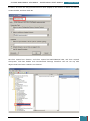
The above settings define a basic unattended installation in which no user input is required
during Windows Setup and the final step in building an answer file is to validate the settings
therein and save them to a file.
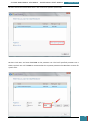
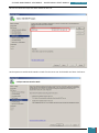
In Windows SIM, we click Tools, and then click Validate Answer File.
GARRETT COLEMAN . STUDENT NO.: 96344598
20
SYSTEMS MANAGEMENT ASSIGNMENT – PROFESSIONAL USER’S MANUAL
July 30, 2014
The setting values in our answer file are compared with the available settings in the Windows
image.
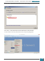
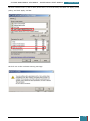
If the answer file validates successfully, a “No warnings or errors” message is generated in the
Messages pane at the bottom of the Windows SIM window. Otherwise, error messages will
appear in the Messages pane.
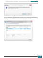
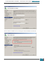
If an error occurs, we can double-click the error message in the Messages pane to navigate to
the incorrect setting and change the setting to fix the error, and then validate again by clicking
Validate Answer File. This step is repeated until the answer file validates.
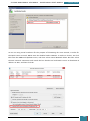
We then navigate to the File menu, click Save Answer File, and save the answer file as
Autounattend.xml.
Finally we copy the Autounattend.xml file to the root directory of a USB flash drive.
We now have a basic answer file that automates a basic unattended installation in which no
user input is required during Windows Setup.
GARRETT COLEMAN . STUDENT NO.: 96344598
21
SYSTEMS MANAGEMENT ASSIGNMENT – PROFESSIONAL USER’S MANUAL
2.3.3
July 30, 2014
Step 3 - Building a Reference Installation
We will now prepare our reference computer to have a customized installation of Windows that
can be duplicated onto one or more destination computers. We do this by using the DVD where
we have saved our Windows 7 .iso file and the answer file that we created in step 1 above.
We turn on the reference computer and insert the Windows 7 DVD and the USB flash drive
containing our answer file named Autounattend.xml.
We then restart the technician computer by pressing the CTRL+ALT+DEL keys. To boot from the
CD/DVD-ROM disc, we override the boot order by pressing the appropriate function key during
initial boot, and setting boot from CD/DVD as the initial boot location.
Windows 7 Setup (Setup.exe) will now begin automatically. By default, Windows Setup will
search the root directory of all removable media for an answer file called Autounattend.xml,
however as VMWare Workstation doesn't recognise USB drives at boot time, it is necessary to
press
shift+F10
to
open
a
command
prompt,
from
where
we
enter
setup.exe/unattend:<thePathToOurUSBDrive> after which Setup will continue, using the
configuration settings from our answer file.
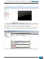
When our installation using the answer file is complete, the computer will reboot to audit
mode. Audit mode is the stage of Windows Setup that enables a user to quickly boot to the
desktop, install additional applications and device drivers, and test the installation.
We next use the sysprep command with the /generalize option to remove hardware-specific
information from the Windows installation, and the /oobe option to configure the computer to
boot to Windows Welcome upon the next restart, so that the computer is prepared for the end
user.
Windows Welcome does not run in audit mode, but it will run the next time the computer
restarts, once we have run the sysprep command with the /oobe option. Windows Welcome,
also known as Machine OOBE (out-of-box experience), prompts the end user to read the
Microsoft Software License Terms and to configure the computer.
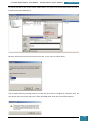
The System Preparation Tool (Sysprep) window is automatically displayed on the desktop in
audit mode, and on this window we select Enter System Out Of Box Experience (OOBE) from the
System Cleanup Action list, tick Generalize, select Shutdown from the Shutdown Options list
and then click OK.
GARRETT COLEMAN . STUDENT NO.: 96344598
22
SYSTEMS MANAGEMENT ASSIGNMENT – PROFESSIONAL USER’S MANUAL
July 30, 2014
Sysprep.exe prepares the image for capture by cleaning up various user- and computer-specific
settings, as well as log files. The reference installation now is complete and ready to be
imaged.
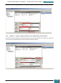
2.3.4
Step 4 - Creating Bootable Windows PE Media
Our next step is to create a bootable Windows PE (Preinstallation Environment) RAM disk on a
CD-ROM disc by using the Copype.cmd script.
Windows PE RAM enables us to start a computer for the purposes of deployment and recovery
by booting directly into memory, enabling us to remove the Windows PE media after the
computer boots.
In step 5 hereunder, we will boot into Windows PE, and use the ImageX tool to capture, modify,
and apply file-based disk images.
On the technician computer, we click Start, All Programs, Windows AIK, where we right-click
Deployment Tools Command Prompt, and then select Run as administrator.
GARRETT COLEMAN . STUDENT NO.: 96344598
23
SYSTEMS MANAGEMENT ASSIGNMENT – PROFESSIONAL USER’S MANUAL
July 30, 2014
The menu shortcut opens a Command Prompt window and automatically sets environment
variables to point to all the necessary tools. By default, all tools are installed at C:\Program
Files\Windows AIK\Tools.
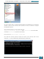
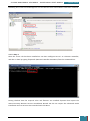
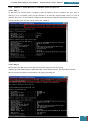
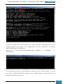
At the command prompt, we run the Copype.cmd script:
copype.cmd <architecture> <destination> where <architecture> can be x86, amd64,
or ia64 and <destination> is a path to a local directory.
In our case we use copype.cmd amd64 c:\winpe_amd64
This creates the necessary directory structure and copies all the necessary files for that
architecture, i.e. \winpe_amd64\winpe_amd64\ISO\winpe_amd64\mount
GARRETT COLEMAN . STUDENT NO.: 96344598
24
SYSTEMS MANAGEMENT ASSIGNMENT – PROFESSIONAL USER’S MANUAL
July 30, 2014
Our next step is to copy the base image named Winpe.wim to the \Winpe_x86\ISO\sources
folder and rename the file to Boot.wim, by using the following script:
copy c:\winpe_amd64\winpe.wim c:\winpe_amd64\ISO\sources\boot.wim
We then Copy ImageX into \Winpe_amd64\ISO by typing:
copy "c:\program files\Windows AIK\Tools\amd64\imagex.exe" c:\winpe_amd64\iso\
GARRETT COLEMAN . STUDENT NO.: 96344598
25
SYSTEMS MANAGEMENT ASSIGNMENT – PROFESSIONAL USER’S MANUAL
July 30, 2014
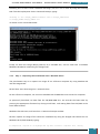
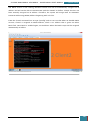
Following this, we then create a Windows PE image (.iso) file. This is done by using the Oscdimg
tool from the Deployment Tools Command Prompt, typing:
oscdimg -n -bc:\winpe_amd64\etfsboot.com c:\winpe_amd64\ISO
c:\winpe_amd64\winpe_amd64.iso
as shown in the screenshot below:
Finally, we burn the image (Winpe_x86.iso) to a CD-ROM disc, and we now have a bootable
Windows PE RAM CD containing the ImageX tool.
2.3.5
Step 5 - Capturing the Installation onto a Network Share
The penultimate step is to capture an image of our reference computer by using Windows PE
and the ImageX tool.
We will then store that image on a network share.
On the reference computer, we insert our Windows PE CD-ROM disc and restart the computer.
As previously described, to boot from the CD/DVD-ROM disc, we override the boot order by
pressing the appropriate function key during initial boot, and setting boot from CD/DVD as the
initial boot location.
Windows then PE starts, and launches a Command Prompt window.
We then capture an image of the reference installation by using the ImageX tool located on our
Windows PE CD/DVD ROM by typing:
E:\imagex.exe /capture D: D:\myimage.wim "my Win7 Install" /compress fast /verify
GARRETT COLEMAN . STUDENT NO.: 96344598
26
SYSTEMS MANAGEMENT ASSIGNMENT – PROFESSIONAL USER’S MANUAL
July 30, 2014
Our next step is to copy the image to a network location, this is possible because Windows PE
provides network support.
On our technician computer, we create a public folder, set with appropriate permissions, on the
desktop called Share.
While Windows PE provides network support, it is important to note that when we boot a
computer with WinPE, the pre-installation environment is configured to obtain an IP address
automatically, and if we don't have DHCP service on the network, the WinPE computer will
obtain an IP address from the Automatic Private IP Address range (APIPA) which is a class B
network address.
GARRETT COLEMAN . STUDENT NO.: 96344598
27
SYSTEMS MANAGEMENT ASSIGNMENT – PROFESSIONAL USER’S MANUAL
July 30, 2014
If we are using Class C network addresses for our technician and reference computer, then,
while the reference computer is booted with WinPE, then the two computers are in different
subnets, and cannot communicate.
Therefore, on our reference computer, at the command prompt, we type:
netsh int ip set address local static 192.168.0.42 255.255.255.0
This sets a static IP address to the reference computer in PE mode that is in the same ipv4
address range as our technician computer, facilitating communication between the two.
Following this, we mount the Share folder as a drive on the reference computer, at the
command prompt, we type
net use N: \\<ComputerName>\<PathToSharedFolder> <password> /user:<userName>
in our case this is:
net use N: \\WIN-QFC9RD5ACBR\Users\Lenovo\Desktop\Share Pa$$w0rd /user:Lenovo
We then change the current drive to the new mounted drive by typing:
N:
The next step is to create a new folder called Images within the new drive by typing:
md Images
Finally, we copy the captured image to our newly created folder by typing:
copy C:\myimage.wim N:\Images
We now have an image of our reference installation, and we can deploy the image onto new
hardware.
GARRETT COLEMAN . STUDENT NO.: 96344598
28
SYSTEMS MANAGEMENT ASSIGNMENT – PROFESSIONAL USER’S MANUAL
2.3.6
July 30, 2014
Step 6 - Deploying from a Network Share
The final step is to use the DiskPart tool to format the hard drive on the reference computer in
order for it to act as a destination computer. We can then copy our image from the network
share.
On the reference computer, we insert our Windows PE media and restart the computer by
pressing the CTRL+ALT+DEL keys.
The reference computer hard drive contains an active partition. Therefore we must override the
boot order to boot from the CD/DVD-ROM drive. During initial boot, we select the appropriate
function key to override the boot order, and Windows PE starts, and launches a Command
Prompt window.
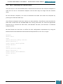
We then format the hard drive to reflect the disk configuration requirements by using the
DiskPart tool from the Windows PE Command Prompt window. In our case, we type:
diskpart
select disk 0
clean
create partition primary size=300
select partition 1
format fs=ntfs label="System"
assign letter=S
active
create partition primary
select partition 2
format fs=ntfs label="Windows"
assign letter=C
exit
GARRETT COLEMAN . STUDENT NO.: 96344598
29
SYSTEMS MANAGEMENT ASSIGNMENT – PROFESSIONAL USER’S MANUAL
July 30, 2014
We can then copy the image from the network share to our local hard drive.
As described above, we mount the Share folder as a drive on the destination computer, at the
command prompt, we type
net use N: \\<ComputerName>\<PathToSharedFolder> <password> /user:<userName>
in our case this is:
net use N: \\WIN-QFC9RD5ACBR\Users\Lenovo\Desktop\Share Pa$$w0rd /user:Lenovo
GARRETT COLEMAN . STUDENT NO.: 96344598
30
SYSTEMS MANAGEMENT ASSIGNMENT – PROFESSIONAL USER’S MANUAL
July 30, 2014
We then copy the image from the Share folder on the technician computer to the hard drive of
the destination computer by typing:
copy N:\Images\myimage.wim C:
Following this we apply the image to the hard drive by using the ImageX tool located on our
Windows PE media by typing:
E:\imagex.exe /apply C:\myimage.wim 1 C:
Finally, we use BCDboot to initialize the Boot Configuration Data (BCD) store and copy boot
environment files to the system partition. We effect this by typing:
C:\windows\system32\bcdboot C:\windows
Success! Our custom image is now deployed onto the destination computer, and it is ready for
use.
GARRETT COLEMAN . STUDENT NO.: 96344598
31
SYSTEMS MANAGEMENT ASSIGNMENT – PROFESSIONAL USER’S MANUAL
3.
July 30, 2014
Part A - Task A2
Microsoft Windows offers the ability to enforce full drive encryption, using a Virtual Machine
Document the process of Implementing Bitlocker in the form of a user instruction manual.
During the process outline any options and or requirements which must be met in order to
setup same.
3.1
Preamble
Windows BitLocker Drive Encryption is a security feature that provides data protection for a
computer, by encrypting all data stored on the Windows operating system volume. We define a
volume as consisting of one or more partitions on one or more hard disks. BitLocker works with
simple volumes, where one volume is one partition.
For best security BitLocker uses a Trusted Platform Module (TPM) to help protect the Windows
operating system and user data, and helps to ensure that a computer, if lost or stolen, or even
left unattended, cannot be tampered with.
A Trusted Platform Module (TPM) is a microchip that is built into a computer and used to store
cryptographic information, such as encryption keys. Information stored on the TPM is generally
more secure from external software attacks and physical theft.
BitLocker can also be used without a TPM by changing the default behavior of the BitLocker
setup wizard using Group Policy. When BitLocker is used without a TPM, the required
encryption keys are stored on a USB flash drive that must be presented to unlock the data
stored on a volume.
3.1.1
How BitLocker Drive Encryption Works
BitLocker Drive Encryption protects data by encrypting the entire Windows operating system
volume.
If the computer is equipped with a compatible TPM, BitLocker uses the TPM to lock the
encryption keys that protect the data. This means that the keys cannot be accessed until the
TPM has verified the state of the computer. The encryption of the entire volume protects all of
the data, including the operating system itself, as well as the Windows registry. As the keys
needed to decrypt data remain locked by the TPM, the data cannot be read just by removing the
hard disk and installing it in another computer.
During startup, the TPM does not release the key that unlocks the encrypted partition until it
has compared a hash of important operating system configuration values with a snapshot taken
earlier, thus verifying the integrity of the Windows startup process. If the TPM detects that the
Windows installation has been tampered with then the key is not released.
GARRETT COLEMAN . STUDENT NO.: 96344598
32
SYSTEMS MANAGEMENT ASSIGNMENT – PROFESSIONAL USER’S MANUAL
July 30, 2014
It is possible to further increase security by combining the use of a TPM with either a PIN
entered by the user or a startup key stored on a USB flash drive.
Where a TPM is not available, BitLocker can provide encryption, without the added security of
locking keys with the TPM, by the the user createing a startup key that is stored on a USB flash
drive.
3.1.2
TPM Definition
A TPM is a microchip that is designed to provide basic security-related functions, primarily
involving encryption keys. It is usually installed on the motherboard of a computer, and
communicates with the rest of the system by means of a hardware bus.
The facility of a TPM allows computers to create cryptographic keys and encrypt them so that
they can be decrypted only by the TPM. This process, known as wrapping or binding a key,
helps to protect the key from disclosure. Each TPM has a unique master wrapping key, the
Storage Root Key (SRK), which is stored within the TPM itself and the private portion of a key
created in a TPM is never exposed.
Computers with a TPM can also create a key that as well as being wrapped, is also tied to
specific hardware or software conditions and this is known as sealing a key. When a sealed key
is first created, the TPM records a snapshot of configuration values and file hashes. A sealed
key is only unsealed or released when those current system values match the ones in the
snapshot. BitLocker uses these sealed keys to detect attacks against the integrity of the
Windows operating system.
With a TPM, private portions of key pairs are kept separated from the memory controlled by the
operating system. Using its own internal firmware and logic circuits for processing instructions,
the TPM does not rely upon the operating system and is not exposed to external software
vulnerabilities.
3.2
System Requirements
3.2.1
Windows Versions
The following versions of windows include BitLocker functionality:
Windows 8.1 Professional Edition
Windows 8.1 Enterprise Edition
Windows Server 2012
Windows Server 2008 R2
Windows Server 2008
Windows 7 Enterprise Edition
Windows 7 Ultimate Edition
Windows Vista Enterprise Edition
Windows Vista Ultimate Edition
GARRETT COLEMAN . STUDENT NO.: 96344598
33
SYSTEMS MANAGEMENT ASSIGNMENT – PROFESSIONAL USER’S MANUAL
3.2.2
July 30, 2014
System Configuration
In order to enable BitLocker drive encryption, the system must be configured as follows:
The computer must either have a TPM of version 1.2 or higher, or a removable USB
memory device, such as a USB flash drive. If the computer doesn’t have TPM version 1.2
or higher, BitLocker will store its key on the flash drive.
The computer must have at least two partitions. One partition must include the drive
Windows is installed on, which is the drive that BitLocker will encrypt. The other
partition is the active partition, which must remain unencrypted so that the computer
can be started.
The system must be formatted with the NTFS file system.
The BIOS must be compatible with TPM and the computer must support USB devices
during computer startup.
3.3
Procedure
In an enterprise environment, BitLocker drive encryption would typically be implemented on the
system drive of a computer with a TPM chip built onto its motherboard. However, as noted
above, it is still possible, though not as secure, to enable BitLocker drive encryption on a
computer that does not have a TPM chip, and as the computer being used for the purpose of
writing this manual is not equipped with a TPM chip, it is this method that we will describe with
the aid of screenshots. However, for the sake of completeness, a description of how to enable
BitLocker drive encryption employing a TPM chip will be described first.
3.3.1
BitLocker Drive Encryption on OS drive of computer with TPM
3.3.1.1 Step 1
We click Start, Control Panel, System and Security, and then BitLocker Drive Encryption.
3.3.1.2 Step 2
We then click Turn On BitLocker for the operating system drive. BitLocker will then scan our
computer to ensure that it meets BitLocker system requirements. If the computer meets
requirements, BitLocker then advises the next steps that need to be taken to turn on BitLocker,
such as drive preparation, turning on the TPM, and encrypting the drive.
This description describes the scenario of encrypting a single partition that holds the operating
system drive, and BitLocker prepares the drive by shrinking the operating system drive and
creating a new system partition to use for system files that are required to start or recover the
operating system and that cannot be encrypted. This new drive will not have a drive letter in
order to help prevent the storing of data files on this drive inadvertently.
After the drive is prepared, we restart the computer.
GARRETT COLEMAN . STUDENT NO.: 96344598
34
SYSTEMS MANAGEMENT ASSIGNMENT – PROFESSIONAL USER’S MANUAL
July 30, 2014
3.3.1.3 Step 3
If the TPM is not initialized, the BitLocker setup wizard instructs us to remove any CDs, DVDs,
or USB drives from the computer and restart the computer to begin the process of turning on
the TPM. We are either prompted to enable the TPM before the operating system boots or in
some cases, depending on the BIOS of the computer, it may be necessary to navigate to the
BIOS options and enable the TPM manually.
Once we confirm that we want the TPM enabled, the operating system will start and the
Initializing the TPM security hardware progress indicator will be displayed.
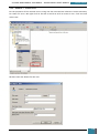
3.3.1.4 Step 4
After the TPM is initialized, the BitLocker setup wizard prompts us to choose how to store the
recovery key, from the following options:
Save the recovery key to a USB flash drive
Save the recovery key to a file (i.e. a network drive or other location)
Print the recovery key
For optimum security, it is advisable to save the recovery key apart from the computer, in our
case we select to save it to a USB flash drive and follow the steps on the wizard accordingly.
The recovery key is required if the encrypted drive is moved to another computer or changes
are made to the system startup information. This recovery key is essential so best practice is to
make additional copies of the key and store them in safe places that can be readily accessed to
recover access to the drive.
3.3.1.5 Step 5
We then confirm that we are ready to encrypt the drive, with the Run BitLocker system check
check box selected, and then click Continue.
We then agree to restart the computer by clicking Restart now.
The computer restarts, and BitLocker checks if the computer meets BitLocker requirements and
is ready for encryption. If it is not, an error message is generated alerting us to the problem
after we have logged on.
A common problem that causes the computer to not meet BitLocker requirements is the
configuration of the system partition.
BitLocker requires a minimum system partition size of 100 MB, and the Windows Recovery
Environment requires 200 MB. When the operating system is installed, the system partition is
automatically created by the setup process with a default size of 300 MB.
GARRETT COLEMAN . STUDENT NO.: 96344598
35
SYSTEMS MANAGEMENT ASSIGNMENT – PROFESSIONAL USER’S MANUAL
July 30, 2014
However, this default partition size can be changed by computer manufacturers or system
administrators when they install the operating system.
If the system partition is exactly 100 MB, BitLocker setup assumes that we have a Windows
Recovery DVD for use with the computer and the system check is completed without any errors.
However, if we have a system partition size between 101 MB and 299 MB, the following error
message is generated: "You will no longer be able to use Windows Recovery Environment unless
it is manually enabled and moved to the system drive."
If we have a Windows 7 DVD that contains the Windows Recovery Environment or we have
another system recovery process in place, we may disregard this message and continue with
BitLocker setup.
Otherwise, it is advisable check our system partition and verify that we have at least 200 MB of
free space on the system partition so that the Windows Recovery Environment can be retained
on the system drive along with the BitLocker Recovery Environment and other files that
BitLocker requires to unlock the operating system drive.
If it is ready for encryption, the Encrypting status bar is displayed, which shows the progress of
the drive encryption.
Encrypting the drive is time consuming and a completion message is displayed when
encryption is finished,
By completing this procedure, we have encrypted the operating system drive and created a
recovery key that is unique to this drive.
The next time we log on, there are no apparent changes, however If the TPM ever changes or
cannot be accessed, if there are changes to key system files, or if someone tries to start the
computer from a disk to circumvent the operating system, the computer will switch to recovery
mode and prevent Windows from starting.
3.3.2
BitLocker Drive Encryption on OS drive of computer with no TPM
Hereunder is the step by step guide to enabling BitLocker drive encryption on a computer that
does not have a TPM chip available.
As noted above, the implementation of BitLocker requires that our computer supports USB
devices during computer startup.
However, we are using a virtual machine by means of VMWare Workstation which does not
support booting to USB. USB drives are not available to the Windows bootloader on VMWare
Workstation, so it cannot read the keys from a passed-through USB flash drive. BitLocker only
GARRETT COLEMAN . STUDENT NO.: 96344598
36
SYSTEMS MANAGEMENT ASSIGNMENT – PROFESSIONAL USER’S MANUAL
July 30, 2014
allows us to write the keys to a USB drive, but the BitLocker boot code can read the keys form
any device, so our workaround is as per the following five steps:
1. We will create a small virtual hard drive that is stored on a USB key and mounted to our
virtual machine.
2. We will change the Group Policy settings in windows to allow BitLocker to work without
a TPM.
3. We will mount a temporary USB drive to our Virtual Machine, and once BitLocker is setup
on the system drive, we will have BitLocker write the Key and Backup key to the
temporary USB.
4. Once BitLocker has written the keys, we will copy them over to the virtual disk, unmount
our first USB drive and allow BitLocker to reboot.
5. BitLocker will then start encrypting after it boots back up.
3.3.2.1 Step 1: Create and Mount a Virtual Hard Drive
Our first step is to provide a permanent location for the BitLocker files. We shut down our
virtual machine, and follow the steps below to add a new virtual hard disk.
Click 'Edit Virtual Machine Settings'
GARRETT COLEMAN . STUDENT NO.: 96344598
37
SYSTEMS MANAGEMENT ASSIGNMENT – PROFESSIONAL USER’S MANUAL
July 30, 2014
Highlight Hard Disk and click 'Add'
For Hardware Type we select 'Hard Disk'
GARRETT COLEMAN . STUDENT NO.: 96344598
38
SYSTEMS MANAGEMENT ASSIGNMENT – PROFESSIONAL USER’S MANUAL
July 30, 2014
We then select to 'Create a new virtual disk'
We only require a small disk, as the keys that will be stored on it are a few kilobytes in size, so
for size we select 10mb.
GARRETT COLEMAN . STUDENT NO.: 96344598
39
SYSTEMS MANAGEMENT ASSIGNMENT – PROFESSIONAL USER’S MANUAL
July 30, 2014
At the Specify Disk File screen we specify the path on our intended removable location
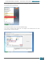
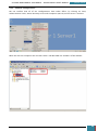
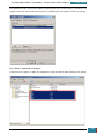
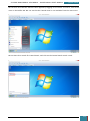
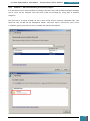
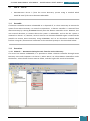
We then boot up the Virtual Machine and from the start menu enter diskmgmt.msc to open
Disk Management.
GARRETT COLEMAN . STUDENT NO.: 96344598
40
SYSTEMS MANAGEMENT ASSIGNMENT – PROFESSIONAL USER’S MANUAL
July 30, 2014
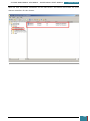
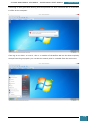
We then initialise the disk as prompted.
We then right-click the Unallocated space and select New Simple Volume to open the wizard
which we follow to completion.
GARRETT COLEMAN . STUDENT NO.: 96344598
41
SYSTEMS MANAGEMENT ASSIGNMENT – PROFESSIONAL USER’S MANUAL
July 30, 2014
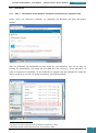
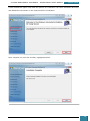
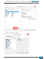
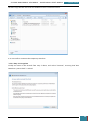
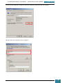
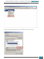
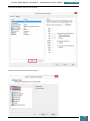
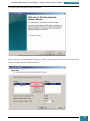
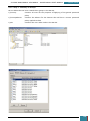
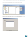
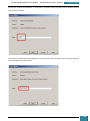
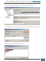
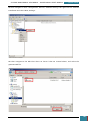
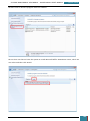
3.3.2.2 Step 2: Group Policy Settings
In order to enable BitLocker without a TPM, we run gpedit.msc from the start menu
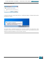
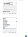
We
then
navigate
to
Computer
Configuration,
Administrative
Templates,
Windows
Components, BitLocker Drive Encryption, Operating System Drives and then double-click on
'require additional authentication at startup'.
GARRETT COLEMAN . STUDENT NO.: 96344598
42
SYSTEMS MANAGEMENT ASSIGNMENT – PROFESSIONAL USER’S MANUAL
July 30, 2014
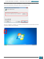
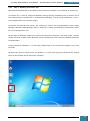
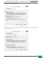
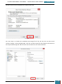
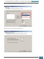
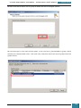
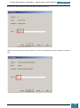
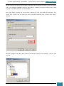
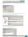
We click the radio button to enable the policy, and tick the option to 'Allow BitLocker without a
compatible TPM'.
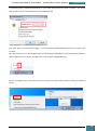
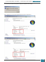
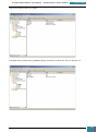
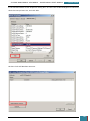
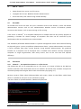
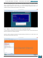
3.3.2.3 Step 3: Setup BitLocker on the System Drive and Write Keys to Temporary USB Drive
Our next step is to mount a temporary USB drive to the virtual machine, by selecting the VM
dropdown menu, removable devices, the USB device name and 'connect (disconnect from host)'
In our Virtual machine, we then have 3 disks. The Main Hard Disk, the small hard disk, and the
USB drive.
GARRETT COLEMAN . STUDENT NO.: 96344598
43
SYSTEMS MANAGEMENT ASSIGNMENT – PROFESSIONAL USER’S MANUAL
July 30, 2014
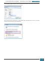
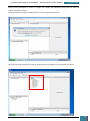
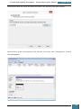
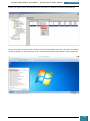
We then open the control panel and navigate to System and Security, and on to the BitLocker
Drive Encryption control panel, where we click 'Turn On BitLocker' for our system Drive.
GARRETT COLEMAN . STUDENT NO.: 96344598
44
SYSTEMS MANAGEMENT ASSIGNMENT – PROFESSIONAL USER’S MANUAL
July 30, 2014
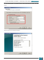
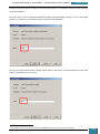
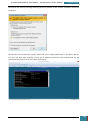
We follow the wizard through to completion and click 'Restart Now' to finish preparing the
system drive.
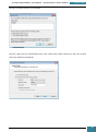
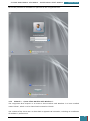
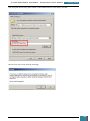
When Windows restarts the BitLocker startup preference dialog is displayed with the only
available option being 'Require a Startup key at every startup', which we click.
GARRETT COLEMAN . STUDENT NO.: 96344598
45
SYSTEMS MANAGEMENT ASSIGNMENT – PROFESSIONAL USER’S MANUAL
July 30, 2014
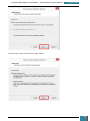
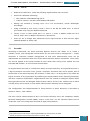
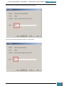
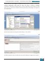
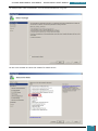
At the next window we select the mounted USB drive (it should be the only option) and click
'Save'.
When prompted, we save the recovery key to the same USB drive for simplicity:
GARRETT COLEMAN . STUDENT NO.: 96344598
46
SYSTEMS MANAGEMENT ASSIGNMENT – PROFESSIONAL USER’S MANUAL
July 30, 2014
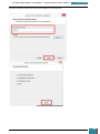
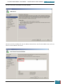
The next window confirms that the recovery key has been saved, at which point we pause,
without closing this window.
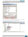
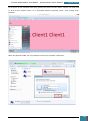
3.3.2.4 Step 4: Copy BitLocker Keys to Virtual Disk
The next step is to open the mounted USB Drive in windows explorer. A .BEK and a .TXT file as
shown below should be visible, if they are not it is necessary to change the folder properties to
display hidden as well as system files.
GARRETT COLEMAN . STUDENT NO.: 96344598
47
SYSTEMS MANAGEMENT ASSIGNMENT – PROFESSIONAL USER’S MANUAL
July 30, 2014
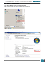
We then copy the two files from the USB drive to our virtual hard drive:
It is now safe to unmount the temporary USB drive.
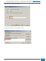
3.3.2.5 Step 5: Encryption
Finally we return to the wizard from step 3 above, and select 'Continue', ensuring that 'Run
BitLocker system check' is ticked.
GARRETT COLEMAN . STUDENT NO.: 96344598
48
SYSTEMS MANAGEMENT ASSIGNMENT – PROFESSIONAL USER’S MANUAL
July 30, 2014
We then select 'Restart now'.
A short time after the system boots back up, a notification popup is displayed advising that
encryption has started.
This process takes a substantial period of time, and when complete, our system drive is then
encrypted, such that if the drive containing the virtual hard drive is not mounted to the virtual
machine, the VM will not boot, nor can it be read in any way.
GARRETT COLEMAN . STUDENT NO.: 96344598
49
SYSTEMS MANAGEMENT ASSIGNMENT – PROFESSIONAL USER’S MANUAL
July 30, 2014
Part B
4.
Part B - Task A
Using Virtual-box, VMware Workstation or similar you are to create several virtual
machines:
Three Servers with server 2008 or later installed
2 of these servers are to be installed with Standard, Enterprise or Datacenter
edition using the full GUI install and named Server1 and Server2 accordingly.
The third server is to be a Standard Server Core installation and named MS-Core
One Client machine with Windows 7 or later installed and named Client1
Clone this Client Virtual Machine and rename the workstation Client2
Please use adequate sizes for the Hard Disk partitions on each of the Client machines.
Configure the servers with 200 GB hard disks. For the Operating System create a
partition of 60 GB accordingly.
RAM on all machines is to be 512 MB or greater depending on your amount of
available RAM
4.1
All passwords are to be Pa$$w0rd.
Give all machines a static IP address from the range 192.168.0.0/24.
Preamble
Windows Server 2008 is a Microsoft server operating system. Windows Server operating
systems
are
built
to
meet
enterprise
requirements
such
as
corporate
networking,
internet/intranet hosting and databases. The main feature that was introduced with Windows
Server was the Active Directory. This user manual describes and explains tasks related to Active
Directory which would typically be carried out in an enterprise environment. Active Directory
can be described as "a directory service that allows businesses to define, manage, access and
secure network resources including files, printers, people and applications"5. Prior to the
introduction of directory systems, users were required to authenticate themselves multiple
times, across multiple servers, to access different resources. Active Directory provides a singlesign in that facilitates access to all resources.
Described hereunder is the procedure for the installation of three different operating systems
(OS). The first OS, Microsoft Windows Server 2008 R2 Datacenter (Full Installation), will be
installed on computers called Server1 and Server2.
Microsoft Windows Server 2008 R2 Standard (Server Core Installation) is the second OS we will
use, and will be installed on a computer called MS-Core. Microsoft Windows Server 2008 R2
Standard (Server Core Installation) provides a minimal installation of Microsoft Windows Server
5
T.Brett, Introduction to Active Directory Services, June 10 , 2014.
GARRETT COLEMAN . STUDENT NO.: 96344598
50
SYSTEMS MANAGEMENT ASSIGNMENT – PROFESSIONAL USER’S MANUAL
July 30, 2014
2008 R2 which supports the installation of limited server roles, for example it cannot provide
an Application Server role or Remote Assistance.
The cost of an OS is often a determining factor in their selection. As noted by Microsoft, ‘The
Full installation option of Windows Server 2008 still installs many services and other
components that are often not needed for a particular usage scenario’6. Therefore the Server
Core Installation may well be the preferred option for an organisation, depending on their
requirements and budget.
Thirdly, two client workstations named Client1 and Client2 will be set up with Microsoft
Windows 7 Professional 64-bit installed on them.
When the required computers are setup and named, with relevant OS installed, we will then
assign static IP addresses to the computers, as per the assignment brief requirement above,
with an address from the range 192.168.0.0/24. This is what is known as a Classless Internet
Domain Routing (CIDR) address. CIDR is regarded as "the method to specify more flexible IP
address classes" 7. CIDR was created as it became clear that available IP addresses were running
out as more individuals and corporations participated on the Internet. As a Class B address
range is usually too large for most companies, and a class C address range may be too small,
CIDR provides the flexibility to increase or decrease the class sizes as necessary. The CIDR
provided, 192.168.0.0/24 represents an IPv4 address and its associated routing prefix
192.168.100.0, or equivalently, its subnet mask 255.255.255.0. The /24 relates to the amount
of 1’s in the subnet mask, i.e. 11111111 11111111 11111111 00000000, which is equal to
255.255.255.0. In summation, 24 bits identify the host portion, 8 bits identify the node.
Therefore we will provide each node on our network with a static IP address of 192.168.0.x,
with x being between 1 and 255, and with a subnet mask of 255.255.255.0.
4.2
System Requirements
The system requirements for the installation of Windows Server 2008 R2 are as follows 8:
Processor: 1.4 GHz 64-bit processor
RAM:
Minimum: 512 MB
Maximum:
32 GB (for Windows Server 2008 R2 Standard)
2 TB (for Windows Server 2008 R2 Enterprise)
2 TB (for Windows Server 2008 R2 Datacenter)
Estimated minimum disk space requirements for the system partition: 32 GB
The system requirements for the installation of Windows 7 Professional 64-bit are as follows 9:
Processor: 1 GHz 32-bit (x86) or 64-bit (x64) processor
6
http://msdn.microsoft.com/en-us/library/dd184075.aspx. Accessed July 17, 2014.
T.Brett, IP Addressing / CIDR, July 8, 2014.
8
http://technet.microsoft.com/en-us/library/dd379511(v=ws.10).aspx. Accessed July 17, 2014.
9
http://windows.microsoft.com/en-IE/windows7/products/system-requirements. Accessed July 17, 2014.
7
GARRETT COLEMAN . STUDENT NO.: 96344598
51
SYSTEMS MANAGEMENT ASSIGNMENT – PROFESSIONAL USER’S MANUAL
RAM: 1 gigabyte (GB) RAM (32-bit) or 2 GB RAM (64-bit)
Disk Space: 16 GB available hard disk space (32-bit) or 20 GB (64-bit)
Graphics: DirectX 9 graphics device with WDDM 1.0 or higher driver
4.3
Procedure
4.3.1
Subtask 1 - Create Three Server Virtual Machines
July 30, 2014
4.3.1.1 Step 1
From VMware Workstation we select File - New Virtual Machine, and select a Typical
(recommended) install. As we will install the operating system later it is not necessary to do a
Custom (advanced) configuration. A typical install is required to enable configuration of Hard
Disk Drive (HDD) partitions during installation.
GARRETT COLEMAN . STUDENT NO.: 96344598
52
SYSTEMS MANAGEMENT ASSIGNMENT – PROFESSIONAL USER’S MANUAL
July 30, 2014
We then select the OS that we want to install, namely Windows Server R2 x64
GARRETT COLEMAN . STUDENT NO.: 96344598
53
SYSTEMS MANAGEMENT ASSIGNMENT – PROFESSIONAL USER’S MANUAL
July 30, 2014
We then name the VM and chose where to save all of the files associated with it
We then set the disk capacity of the virtual HDD at 200GB as specified in the assignment brief.
We select the option to Split virtual disk into multiple files, which results in the use of thin
provisioning (i.e. the VM grows as the files grow), avoiding the full 200GB being immediately
taken from the host machine.
GARRETT COLEMAN . STUDENT NO.: 96344598
54
SYSTEMS MANAGEMENT ASSIGNMENT – PROFESSIONAL USER’S MANUAL
July 30, 2014
We then click Finish to complete the creation of the VM.
Our next step is to locate the installation ISO image file of the OS. We click on Edit virtual
machine settings, select CD/DVD (IDE), click the Use ISO image file radio button and browse to
the required ISO image file. We can then click on Power on this virtual machine.
GARRETT COLEMAN . STUDENT NO.: 96344598
55
SYSTEMS MANAGEMENT ASSIGNMENT – PROFESSIONAL USER’S MANUAL
July 30, 2014
4.3.1.2 Step 2 - Installation of Windows Server Operating Systems
When we power on the VM the Windows Server 2008 R2 installation begins.
During the installation process we select the Windows Server 2008 Datacentre (Full Installation)
for Server 1 and Server 2.
GARRETT COLEMAN . STUDENT NO.: 96344598
56
SYSTEMS MANAGEMENT ASSIGNMENT – PROFESSIONAL USER’S MANUAL
July 30, 2014
We select the Windows Server 2008 R2 Datacentre (Server Core Installation) for the MS-Core
Server VM.
We follow the installation wizard until we reach the installation type window where we select
Custom (Advanced) installation in order to allow us to partition the HDD during the installation.
GARRETT COLEMAN . STUDENT NO.: 96344598
57
SYSTEMS MANAGEMENT ASSIGNMENT – PROFESSIONAL USER’S MANUAL
July 30, 2014
We then select the unformatted drive and click Drive options (advanced).
We then click New, and enter 60820MB as the partition size. The brief specified partition size is
60GB, to which we add 100MB to accommodate the separate partition that Windows creates for
system files.
GARRETT COLEMAN . STUDENT NO.: 96344598
58
SYSTEMS MANAGEMENT ASSIGNMENT – PROFESSIONAL USER’S MANUAL
July 30, 2014
The next window shows the partitions that have been created, we select the 60GB partition as
the location to install Windows, and click Next to proceed with the installation.
GARRETT COLEMAN . STUDENT NO.: 96344598
59
SYSTEMS MANAGEMENT ASSIGNMENT – PROFESSIONAL USER’S MANUAL
July 30, 2014
The installation then commences.
Once the installation has completed we are required to create the Administrator password.
GARRETT COLEMAN . STUDENT NO.: 96344598
60
SYSTEMS MANAGEMENT ASSIGNMENT – PROFESSIONAL USER’S MANUAL
July 30, 2014
We set the password as Pa$$w0rd as specified in the assignment brief.
4.3.2
Subtask 2 - Create Client Machine with Windows 7
The assignment brief requires us to create a client machine with Windows 7 or later installed
named Client1, which is to be cloned and renamed as Client2.
The creation of the client VM is as described in Appendix D hereunder, including an installation
of windows 7 professional.
GARRETT COLEMAN . STUDENT NO.: 96344598
61
SYSTEMS MANAGEMENT ASSIGNMENT – PROFESSIONAL USER’S MANUAL
July 30, 2014
In order to minimise resources used by the virtual machines, and to provide redundancy in the
event of failure of any of the VMs, we will create linked clones of all of our VMs.
Linked clones allow us to install an operating system once and make copies of it, whereby the
OS that is being cloned is used as a base image, and the cloned VM uses the base image when
it is powered on. This means that the cloned VM uses significantly less space as it does not
need the initial OS space that a newly created VM normally uses.
The description hereunder is of the cloning of our Server1 VM, and can be applied for the
cloning of the other VMs.
4.3.2.1 Step 1
From the VMWare Workstation library we right click on the VM we wish to clone, select Manage
and click Clone, to open the Clone Virtual Machine Wizard, which we follow as shown.
GARRETT COLEMAN . STUDENT NO.: 96344598
62
SYSTEMS MANAGEMENT ASSIGNMENT – PROFESSIONAL USER’S MANUAL
July 30, 2014
We select the Create a linked clone radio button.
GARRETT COLEMAN . STUDENT NO.: 96344598
63
SYSTEMS MANAGEMENT ASSIGNMENT – PROFESSIONAL USER’S MANUAL
July 30, 2014
We then name the clone and chose the location for the VM's file.
GARRETT COLEMAN . STUDENT NO.: 96344598
64
SYSTEMS MANAGEMENT ASSIGNMENT – PROFESSIONAL USER’S MANUAL
4.3.3
July 30, 2014
Subtask 3 - Computer Names
4.3.3.1 Step 1 - Rename Server 1 and Server 2 Machines
From the start menu we right click on Computer and click Properties
From the System window we click Change settings
GARRETT COLEMAN . STUDENT NO.: 96344598
65
SYSTEMS MANAGEMENT ASSIGNMENT – PROFESSIONAL USER’S MANUAL
July 30, 2014
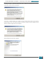
On the System Properties window we open the Computer Name tab and click Change.
We then enter the computer name as applies.
GARRETT COLEMAN . STUDENT NO.: 96344598
66
SYSTEMS MANAGEMENT ASSIGNMENT – PROFESSIONAL USER’S MANUAL
July 30, 2014
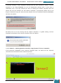
It is necessary to restart the computer to apply the computer name change.
Once complete, we can see the required names for Server1 and Server 2.
GARRETT COLEMAN . STUDENT NO.: 96344598
67
SYSTEMS MANAGEMENT ASSIGNMENT – PROFESSIONAL USER’S MANUAL
July 30, 2014
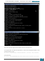
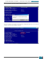
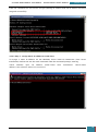
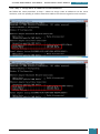
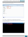
4.3.3.2 Step 2 - Rename MS-Core Machine
To change the name of the Server Core machine, we enter 'sconfig.cmd' from the command
prompt.
This opens the server configuration interface, where we enter '2' for Computer Name, which
allows us to enter the name we want for the computer.
GARRETT COLEMAN . STUDENT NO.: 96344598
68
SYSTEMS MANAGEMENT ASSIGNMENT – PROFESSIONAL USER’S MANUAL
July 30, 2014
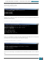
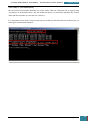
We are prompted to restart the computer to apply the changes.
Once the computer has restarted, by entering Server Configuration again we can see that the
computer name has been changed as required.
GARRETT COLEMAN . STUDENT NO.: 96344598
69
SYSTEMS MANAGEMENT ASSIGNMENT – PROFESSIONAL USER’S MANUAL
July 30, 2014
4.3.3.3 Step 3 - Rename Client 1 and Client 2 Machines
The same procedure as described above for renaming Server1 and Server2 is followed to
rename the two client machines.
GARRETT COLEMAN . STUDENT NO.: 96344598
70
SYSTEMS MANAGEMENT ASSIGNMENT – PROFESSIONAL USER’S MANUAL
4.3.4
July 30, 2014
Subtask 4 - Assign Static IP Addresses to all Machines
When we need a computer to always use a specific IP address, such as a server, it is necessary
to assign it a static IP address.
By default, TCP/IP settings are configured to for nodes on a network to receive an address
automatically from a Dynamic Host Configuration Protocol (DHCP) server on the network, and it
is not necessary to manually configure TCP/IP settings. However automatically assigned IP
addresses are subject to change, and so, in order to ensure reliable communication between
nodes on a network we use static IP addresses.
In order to assign a static IP address we must fist ensure that the address we wish to assign is
not in the DHCP range of addresses that may be automatically assigned , and avoid the risk of
an IP address being assigned statically and dynaically. IP address conflict will also ensue if we
attempt to assign an IP address that has already been assigned to another computer.
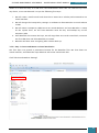
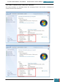
4.3.4.1 Step 1 - Assign Static IP Addresses to Server1 and Server2
To statically assign an IP address on either of our Windows Server 2008 R" Datacentre (Full
Installation) machines we firstly select Configure networking from the Initial Configuration
Tasks window. Alternatively we can search for View Network Connections from the start menu
to open the same window, and this is how the window is accessed from our windows 7 client
machines.
GARRETT COLEMAN . STUDENT NO.: 96344598
71
SYSTEMS MANAGEMENT ASSIGNMENT – PROFESSIONAL USER’S MANUAL
July 30, 2014
We right click on our Local Area Connection and select properties.
We then select the Internet Protocol Version 4 (TCP/IPv4) item and click Properties.
GARRETT COLEMAN . STUDENT NO.: 96344598
72
SYSTEMS MANAGEMENT ASSIGNMENT – PROFESSIONAL USER’S MANUAL
July 30, 2014
We then select the Use the following IP address radio button, which allows us to enter the IP
address we wish to use for this machine, along with the Subnet mask. As we are using a private
network there is no need to enter a default gateway address.
From the command line on Server1 we type ipconfig to confirm that the IP address has been
assigned successfully.
GARRETT COLEMAN . STUDENT NO.: 96344598
73
SYSTEMS MANAGEMENT ASSIGNMENT – PROFESSIONAL USER’S MANUAL
July 30, 2014
From the command line on Server2 we type ipconfig to confirm that the IP address has been
assigned successfully.
4.3.4.2 Step 2 - Assign Static IP Addresses to MS-Core
To assign a static IP address on our Windows Server 2008 R2 Datacentre (Core Server
Installation) machine we use the netsh command from the command prompt, entering:
'netsh
interface
ipv4
set
address
name="Local
Area
Connection"
source=static
address=192.168.0.23 mask=255.255.255.0'
GARRETT COLEMAN . STUDENT NO.: 96344598
74
SYSTEMS MANAGEMENT ASSIGNMENT – PROFESSIONAL USER’S MANUAL
July 30, 2014
4.3.4.3 Step 3 - Assign Static IP Addresses to Client Machines
We follow the same procedure as Step 1 above to assign static IP addresses to the client
machines, and use ipconfig to confirm that the IP address has been assigned to each machine.
GARRETT COLEMAN . STUDENT NO.: 96344598
75
SYSTEMS MANAGEMENT ASSIGNMENT – PROFESSIONAL USER’S MANUAL
July 30, 2014
4.3.4.4 Step 4 - Test Connectivity
We can test the connections between any of the nodes from the command line by typing 'ping
<ip address of destination node>. We see below that there is a connection between the current
node and the computer at 192.168.0.21 (Server1).
It is important to note that it may be necessary to disable the firewall from the machines we are
wishing to communicate between.
GARRETT COLEMAN . STUDENT NO.: 96344598
76
SYSTEMS MANAGEMENT ASSIGNMENT – PROFESSIONAL USER’S MANUAL
5.
5.1
July 30, 2014
Part B - Task B
Please configure the following Forest settings:
Server1 is to be a Domain Controller of a tree called MSCCONV.IPA
Client 1 is to be a workstation member of MSCCONV.IPA
Server2 is to be setup as a second domain controller of MSCCONV.IPA
MS-Core is to be a member server of MSCCONV.IPA
Preamble
Servers within a domain are set up as either a member server or a domain controller (DC). A
domain controller is a server on the domain network that controls host access to Windows
domain resources. Domain controllers in a network are commonly described as "the centrepiece
of the Active Directory Service"10. The domain controller stores user account information (global
catalog), authenticates users and enforces security policy for a Windows domain .
Microsoft recommend the use of more than one domain controller in a domain, so that a
domain can continue to function if a domain controller fails or must be disconnected
11
. A
second domain controller can also be used as a means of balancing the workload of a network.
We will be setting up Server2 as a second domain controller in our domain.
Another type of domain controller worth noting is a Read-Only Domain Controller (RODC). The
RODC hosts read-only parts of the Active Directory database. A RODC can only receive
replicated data from other domain controllers and cannot initiate any replication. RODC’s are
typically used in satellite locations of an organisation, where access to Active Directory is
required but the security around the server is less secure.
Active Directory can be made up of multiple domains called trees. A tree is a collection of
domains with a common namespace, such as guinness.diageo.local and baileys.diageo.local.
The entire container within Active Directory is called a Forest, which is a group of one or more
domains.
When setting up a domain controller, we must specify a Fully Qualified Domain Name (FQDN). If
this is the very first domain in the forest it is referred to as the forest root domain. An FQDN
has two elements, the first being the name of the network such as in our case MSCONV, and
the second part is referred to as a top-level domain. Examples of top-level domains are .com
.net etc. However, in Active Directory a valid top-level domain is not required. The most
commonly used one is .local, however we will be using .IPA.
When the domain controllers have been setup, nodes can then be connected to the DC and
become members of the domain. As members of the domain, they can be assigned privileges
10
11
http://www.techopedia.com/definition/4193/domain-controller. Accessed July 18, 2014.
http://technet.microsoft.com/en-us/library/cc738032(v=ws.10).aspx. Accessed July 18, 2014.
GARRETT COLEMAN . STUDENT NO.: 96344598
77
SYSTEMS MANAGEMENT ASSIGNMENT – PROFESSIONAL USER’S MANUAL
July 30, 2014
to access certain resources such as printers and files. Access to certain resources can also be
restricted. The Client1, Client2 and MS-Core machines will be setup as members of our domain.
In order to setup a domain, Active Directory Domain Services must be installed as a role.
Microsoft Active Directory Domain Services are the foundation for distributed networks built in
Microsoft Windows Server 2008 operating systems that use Domain Controllers. Active
Directory Domain Services "provide secure, structured, hierarchical data storage for objects in a
network such as users, computers, printers, and services.12"
5.2
Procedure
5.2.1
Subtask 1 - Setup Server1 as a Domain Controller of the Tree
5.2.1.1 Step 1
Our first step will be to set up a domain, and in order to do this Active Directory Services must
be installed as a role on our server. We open Server Manager and select Add Roles.
12
http://msdn.microsoft.com/en-us/library/aa362244(v=vs.85).aspx. Accessed July 18, 2014.
GARRETT COLEMAN . STUDENT NO.: 96344598
78
SYSTEMS MANAGEMENT ASSIGNMENT – PROFESSIONAL USER’S MANUAL
July 30, 2014
The first page of the Add Roles Wizard requires us to confirm that certain steps have been
completed, such as the Administrator account having a strong password.
At the next window we select Active Directory Domain Services as the role we wish to install.
GARRETT COLEMAN . STUDENT NO.: 96344598
79
SYSTEMS MANAGEMENT ASSIGNMENT – PROFESSIONAL USER’S MANUAL
July 30, 2014
We then click to Add Required Features for the installation.
The next window gives further details concerning the server role.
GARRETT COLEMAN . STUDENT NO.: 96344598
80
SYSTEMS MANAGEMENT ASSIGNMENT – PROFESSIONAL USER’S MANUAL
July 30, 2014
We then confirm the installation selections by clicking Install.
The Installation Results window confirms the successful installation of our specific server roles
and features.
GARRETT COLEMAN . STUDENT NO.: 96344598
81
SYSTEMS MANAGEMENT ASSIGNMENT – PROFESSIONAL USER’S MANUAL
July 30, 2014
Following this, from Server Manager we can see that the roles and features have been installed.
5.2.1.2 Step 2
Once the server role has been installed we can then configure Server1 as a domain controller,
and this is done by typing 'dcpromo' (Domain Controller Promoter) from the command line.
Having checked that the required roles and features are installed dcpromo then opens the
Active Directory Domain Services Installation Wizard. We do not require the advanced mode
installation and so we leave this unticked and click Next.
GARRETT COLEMAN . STUDENT NO.: 96344598
82
SYSTEMS MANAGEMENT ASSIGNMENT – PROFESSIONAL USER’S MANUAL
July 30, 2014
The next window describes some of the new features inherent in Windows Server 2008.
GARRETT COLEMAN . STUDENT NO.: 96344598
83
SYSTEMS MANAGEMENT ASSIGNMENT – PROFESSIONAL USER’S MANUAL
July 30, 2014
The next window offers the option to add a domain controller to an existing domain, create a
new domain in an existing forest, or create a new domain in a new forest. We are creating a
new domain in a new forest and so we click this radio button.
At the next window we enter the assignment specified Fully Qualified Domain Name (FQDN)
GARRETT COLEMAN . STUDENT NO.: 96344598
84
SYSTEMS MANAGEMENT ASSIGNMENT – PROFESSIONAL USER’S MANUAL
July 30, 2014
The next two windows allow us to enable backward compatibility so that any Windows Server
2003 or Windows Server 2008 servers will be compatible with our new domain as regards
Forest Functional Level and Domain Functional Level.
GARRETT COLEMAN . STUDENT NO.: 96344598
85
SYSTEMS MANAGEMENT ASSIGNMENT – PROFESSIONAL USER’S MANUAL
July 30, 2014
As we are currently installing our first domain controller, the only additional option available is
DNS Server, which we select.
A warning message is then displayed which we can ignore as the server will be configured later.
GARRETT COLEMAN . STUDENT NO.: 96344598
86
SYSTEMS MANAGEMENT ASSIGNMENT – PROFESSIONAL USER’S MANUAL
July 30, 2014
We can then specify locations for database, log files and SYVOL to be stored, which we leave as
default.
The next step is to create the Directory Services Restore Mode (DSRM) password, which is used
in the event of the Active Directory requiring to be restored or maintained, and as such this
password should be recorded and stored in a safe place such as a fire-proof safe.
GARRETT COLEMAN . STUDENT NO.: 96344598
87
SYSTEMS MANAGEMENT ASSIGNMENT – PROFESSIONAL USER’S MANUAL
July 30, 2014
The next window gives a summary of selected settings which can be exported to allow the
same installation to be rolled out on several computers.
The wizard then configures Active Directory Domain Services as we have directed.
Finally we click Finish to complete the installation and are then prompted to restart the
computer to initialise the settings.
GARRETT COLEMAN . STUDENT NO.: 96344598
88
SYSTEMS MANAGEMENT ASSIGNMENT – PROFESSIONAL USER’S MANUAL
5.2.2
July 30, 2014
Subtask 2 - Setup Client1 as a Workstation Member of the Tree
5.2.2.1 Step 1
To setup client1 as a workstation member of the domain server, we firstly setup the member on
the same network as the domain server. We previously assigned a static IP address to client1
within the same range as Server1, and we now set the IP address of Server1 as the preferred
DNS of client1, setting the IP address of Server2 as the alternate DNS address (Server2 will be
set up as a second domain controller later)
GARRETT COLEMAN . STUDENT NO.: 96344598
89
SYSTEMS MANAGEMENT ASSIGNMENT – PROFESSIONAL USER’S MANUAL
July 30, 2014
The next step is to add Client1 as a member of our domain which we effect by opening System
Properties and clicking Change. We then select the Member of Domain radio button and enter
the FQDN for our domain as previously specified.
We then enter the Administrator password in order to get permission to join the domain.
GARRETT COLEMAN . STUDENT NO.: 96344598
90
SYSTEMS MANAGEMENT ASSIGNMENT – PROFESSIONAL USER’S MANUAL
July 30, 2014
A message advises us that the computer is now a member of the domain.
In order to effect the changes it is necessary to restart the computer.
Once the computer has restarted, by right clicking on computer from the start menu and
selecting properties, we can see that the computer is now a member of the domain.
GARRETT COLEMAN . STUDENT NO.: 96344598
91
SYSTEMS MANAGEMENT ASSIGNMENT – PROFESSIONAL USER’S MANUAL
5.2.3
July 30, 2014
Subtask 3 - Setup Server2 as a Second Domain Controller of the Tree
5.2.3.1 Step 1
Similarly to the steps above, the first step in adding Server2 as a second domain controller to
our domain is, given that Server2 has already been assigned a static IP address within the same
range as Server1, to add the IP address of Server1 as the preferred DNS of Server2.
5.2.3.2 Step 2
As with Server1 we enter 'dcpromo' from the command line.
GARRETT COLEMAN . STUDENT NO.: 96344598
92
SYSTEMS MANAGEMENT ASSIGNMENT – PROFESSIONAL USER’S MANUAL
July 30, 2014
We follow the steps as with Server1, however for Server2 we select the Add a domain controller
to an existing domain radio button.
We then enter the FQDN for our domain and click Set to enter the credentials for this machine.
GARRETT COLEMAN . STUDENT NO.: 96344598
93
SYSTEMS MANAGEMENT ASSIGNMENT – PROFESSIONAL USER’S MANUAL
July 30, 2014
We then enter the Administrator credentials, and click next on the Wizard.
GARRETT COLEMAN . STUDENT NO.: 96344598
94
SYSTEMS MANAGEMENT ASSIGNMENT – PROFESSIONAL USER’S MANUAL
July 30, 2014
Our domain is then displayed as the domain for the additional domain controller.
We accept the default site for the new domain controller.
GARRETT COLEMAN . STUDENT NO.: 96344598
95
SYSTEMS MANAGEMENT ASSIGNMENT – PROFESSIONAL USER’S MANUAL
July 30, 2014
For the second domain controller additional options we select DNS Server and Global catalog.
The remaining steps of the Wizard are as per those described in Server1 above, which we follow
to completion.
GARRETT COLEMAN . STUDENT NO.: 96344598
96
SYSTEMS MANAGEMENT ASSIGNMENT – PROFESSIONAL USER’S MANUAL
July 30, 2014
GARRETT COLEMAN . STUDENT NO.: 96344598
97
SYSTEMS MANAGEMENT ASSIGNMENT – PROFESSIONAL USER’S MANUAL
5.2.4
July 30, 2014
Subtask 4 - Setup MS-Core as a Member Server of the Tree
5.2.4.1 Step 1
As MS-Core has already been assigned a static IP address on our network, the first step in
setting it u as a member server of our domain is to add the required DNS server, i.e. the IP
address of Server1, to its network configuration. We do this from the command line by typing:
'netsh interface ipv4 set dns "Local" static 192.168.0.21'
5.2.4.2 Step 2
We can then join MS-Core to the domain from the command line by typing:
'netdom join MS-CORE /domain:MSCCONV.IPA /userd:Administrator /passwordd:Pa$$w0rd'
We can confirm the above configurations by typing ipconfig/all.
GARRETT COLEMAN . STUDENT NO.: 96344598
98
SYSTEMS MANAGEMENT ASSIGNMENT – PROFESSIONAL USER’S MANUAL
5.2.5
July 30, 2014
Confirm Configurations
We can confirm that all of our configurations have taken effect, by clicking on Start,
Administrative Tasks, Active Directory Users and Computers (AD UC) on the Server1 machine.
When we click on Computers we see that Client1 and MS-CORE are members of the domain.
GARRETT COLEMAN . STUDENT NO.: 96344598
99
SYSTEMS MANAGEMENT ASSIGNMENT – PROFESSIONAL USER’S MANUAL
July 30, 2014
When we click on Domain Controllers we see that Server1 and Server2 have been set up as
domain controllers for this domain.
GARRETT COLEMAN . STUDENT NO.: 96344598
100
SYSTEMS MANAGEMENT ASSIGNMENT – PROFESSIONAL USER’S MANUAL
6.
July 30, 2014
Part B - Task C
Install 2 additional hard disks of 150 GB, on Server1 and configure them to:
Using these disks, use one to Mirror the operating system disk
Using the remaining available space available, Create a Spanned volume which is to use
all of the remaining free space on all disks.
6.1
Preamble
In an enterprise environment, the installation of two additional hard disks on a server would
involve the opening of the server case, and installing the correct SCSI drives. As the tasks
described in this user manual were carried out using virtual machines, two additional hard
drives were added in VMWare Workstation.
The mirroring of a disk is a form of Redundant Array of Independent Disks (RAID) technology.
that is also known as RAID 1. RAID can be defined as "a data storage virtualization technology
that combines multiple disk drive components into a logical unit for the purposes of data
redundancy or performance improvement"13.
When mirroring is implemented, data is written identically to two (or more) drives, thereby
producing a "mirrored set". The read request is serviced by any of the drives containing the
requested data, and this can improve read performance. However, write performance can be
reduced because all drives must be updated; thus the write performance is determined by the
slowest drive. The array continues to operate as long as at least one drive is functioning
The implementation of RAID can be managed either by dedicated computer hardware or by
software. This ser manual describes a software solution, that is part of the operating system.
A spanned volume is "a dynamic volume consisting of disk space on more than one physical
disk"14. If a simple volume exists that is not a system volume or boot volume, it can be
extended across additional disks to create a spanned volume. A spanned volume can also be
created in unallocated space on a dynamic disk.
You need at least two dynamic disks in addition to the startup disk to create a spanned volume.
You can extend a spanned volume onto a maximum of 32 dynamic disks.
13
14
Arpaci-Dusseau, R. H., & Arpaci-Dusseau, A. C. (2012). Operating Systems: Three Easy Pieces.
http://technet.microsoft.com/en-us/library/cc772180.aspx. Accessed July 19, 2014.
GARRETT COLEMAN . STUDENT NO.: 96344598
101
SYSTEMS MANAGEMENT ASSIGNMENT – PROFESSIONAL USER’S MANUAL
6.2
July 30, 2014
System Requirements
6.2.1 - Disk Mirroring
As advised by microsoft
15
, in Windows Server 2008 R2, as long as there is one additional
hard disk, it is possible to set up mirroring (RAID1) for the operating system volume using
only tools already built into the operating system.
No special software or hardware is required.
Once the disk mirror is set up, the operating system and data will be present on both boot
disks, and the system software will keep data and changes to the operating system (such
as registry updates) in sync on both boot disks.
If the primary boot disk should fail, the computer can switch over and boot from the
secondary boot disk.
6.2.2 - Spanned Volume
Microsoft note that simple volumes on dynamic disks can be extended on the same disk or
set to span other disks, without restarting the computer, if more disk space is required 16.
A simple volume can only be extended if the file system is NTFS.
A volume that existed before the disk was upgraded to dynamic, can never be extended or
spanned.
It is not possible to extend a System or Boot volume.
6.3
Procedure
6.3.1
Subtask 1 - Install 2 Additional Hard Disks on Server 1
To add a hard disk (HDD) to the Server1 VM we right click on the VM and select Settings.
15
16
http://www.microsoft.com/en-ie/download/details.aspx?id=23476. Accessed July 19, 2014.
http://support.microsoft.com/kb/225551. Accessed July 19, 2014.
GARRETT COLEMAN . STUDENT NO.: 96344598
102
SYSTEMS MANAGEMENT ASSIGNMENT – PROFESSIONAL USER’S MANUAL
July 30, 2014
From the Hardware tab we click on Add.
We then select Hard Disk and click Next.
GARRETT COLEMAN . STUDENT NO.: 96344598
103
SYSTEMS MANAGEMENT ASSIGNMENT – PROFESSIONAL USER’S MANUAL
July 30, 2014
We then follow the steps as described in Appendix D hereunder for the setting up of a VM.
GARRETT COLEMAN . STUDENT NO.: 96344598
104
SYSTEMS MANAGEMENT ASSIGNMENT – PROFESSIONAL USER’S MANUAL
July 30, 2014
At the Specify Disk Capacity window we enter 150GB as specified in the brief, for each
additional HDD.
GARRETT COLEMAN . STUDENT NO.: 96344598
105
SYSTEMS MANAGEMENT ASSIGNMENT – PROFESSIONAL USER’S MANUAL
July 30, 2014
From VMWare Workstation we can then see that the 2 additional Hard disks have been added.
6.3.2
Subtask 2 - Use an Additional Hard Disk to Mirror the OS Disk
To manage HDDs on Server1, from Server Manager we select Storage, Disk Management. We
then right click on each of the newly added HDDs and click Online to make them available.
GARRETT COLEMAN . STUDENT NO.: 96344598
106
SYSTEMS MANAGEMENT ASSIGNMENT – PROFESSIONAL USER’S MANUAL
July 30, 2014
To mirror the OS to one of our newly added disks, we right click the partition where the OS is
installed and select Add Mirror.
We then select the disk we wish to mirror the OS, in our case we select Disk 1.
The resultant warning message advises us that the disk will be changed to a dynamic disk, we
will not be able to start any more OS’s from the HDD other than the current boot volume.
GARRETT COLEMAN . STUDENT NO.: 96344598
107
SYSTEMS MANAGEMENT ASSIGNMENT – PROFESSIONAL USER’S MANUAL
July 30, 2014
We then see that the two partitions are synced, coloured maroon to indicate mirrored volumes.
6.3.3
Subtask 3 - Create a Spanned Volume to Use Remaining Free Disk Space
In order to create a spanned volume that uses the remaining available disk space, we right click
on any of the unallocated space and select New Spanned Volume.
GARRETT COLEMAN . STUDENT NO.: 96344598
108
SYSTEMS MANAGEMENT ASSIGNMENT – PROFESSIONAL USER’S MANUAL
July 30, 2014
This opens the New Spanned Volume Wizard.
We can then see the unallocated space on all disks, and we select each of the disks and click
Add to include it on our spanned volume.
GARRETT COLEMAN . STUDENT NO.: 96344598
109
SYSTEMS MANAGEMENT ASSIGNMENT – PROFESSIONAL USER’S MANUAL
July 30, 2014
Once the available space has been selected we click Next.
We then assign a drive letter to the spanned volume.
GARRETT COLEMAN . STUDENT NO.: 96344598
110
SYSTEMS MANAGEMENT ASSIGNMENT – PROFESSIONAL USER’S MANUAL
July 30, 2014
The next window allows us to format the drive, and we select NTFS file system, and quick
format.
We then click Finish to complete the Wizard.
GARRETT COLEMAN . STUDENT NO.: 96344598
111
SYSTEMS MANAGEMENT ASSIGNMENT – PROFESSIONAL USER’S MANUAL
July 30, 2014
A similar warning message to when mirroring is displayed, which we accept and then spanning
is carried out.
Upon completion of the above tasks we can see our mirrored disks coloured maroon, and our
spanned volume in purple across the three disks.
GARRETT COLEMAN . STUDENT NO.: 96344598
112
SYSTEMS MANAGEMENT ASSIGNMENT – PROFESSIONAL USER’S MANUAL
7.
July 30, 2014
Part B - Task D
Within Active Directory, create the following organisational unit structure:
Parent OU called IPA containing:
Two child OUs called Marketing and IT.
IT OU to contain 2 sub OUs called Dublin and Belfast.
Identify any method of creating users via a TUI environment, outline advantages
accordingly.
Using a method of your choice, Create 5 users in the IPA OU called user1 to user10
(first name only) using the default Pa$$w0rd.
Create 3 users in sales called user11 to user15, 3 users in Dublin called user16 to
user18, and 2 users in Belfast called user19 and user20.
Users are not to change their passwords at first login and are to have 24 hour logins
enabled, Monday to Friday only.
7.1
Preamble
According to Microsoft, the Active Directory Domain Services role allows us to "create a
scalable, secure, and manageable infrastructure for user and resource management."17. Simply
described, it centralise network management so that most administrative tasks can be
implemented and controlled from one of the Active Directory Domain Controllers. These tasks
can also be applied to the whole network at once rather than having to be applied on each
individual AD member, as we will illustrate hereunder.
An organisational unit (OU) is a subdivision within an Active Directory. An organisational unit is
a logical container into which users, groups, computers and other OUs can be placed. One of
the benefits of An Active Directory OU structure is often cited
18
as being that it can reflect the
logical structure of an organisation by modelling the organisational chart, depicting employees
and their respective departments. Organisational units are created to configure objects within
the organisational unit and delegate administrative control. An OU is the smallest unit to which
a Group Policy can be linked, or over which administrative authority can be delegated.
The configuration and implementation of Group Policies in Active Directory is described in
Section 8: Part B - Task E below.
The main GUI for administration of OUs is the Active Directory Users and Computers (ADUC)
Microsoft Management Console (MMC) snap-in. From here, we will illustrate below how to
create OUs, new users and groups and how to apply Group Policies.
17
18
http://technet.microsoft.com/en-us/library/hh831484.aspx. Accessed July 19, 2014.
T.Brett, Introduction to Active Directory Services, June 10 , 2014.
GARRETT COLEMAN . STUDENT NO.: 96344598
113
SYSTEMS MANAGEMENT ASSIGNMENT – PROFESSIONAL USER’S MANUAL
7.2
Procedure
7.2.1
Subtask 1 - Create Organisational Unit Structure
July 30, 2014
To create Organisational Units (OU), we click Start, Administrative Tools, Active Directory Users
and Computers (AD UC).
We then right click on our domain, select New, and click Organisational Unit.
GARRETT COLEMAN . STUDENT NO.: 96344598
114
SYSTEMS MANAGEMENT ASSIGNMENT – PROFESSIONAL USER’S MANUAL
July 30, 2014
We then name the OU as required, in this case IPA. We also tick the Protect container from
accidental deletion tickbox.
In order to create a nested OU within the IPA OU we simply right click on the IPA OU and select
New, Organisational Unit, which can then be named appropriately.
GARRETT COLEMAN . STUDENT NO.: 96344598
115
SYSTEMS MANAGEMENT ASSIGNMENT – PROFESSIONAL USER’S MANUAL
July 30, 2014
This process is repeated for the specified required OUs, leaving an Organisational Unit
structure as shown below. Organisational Units are represented by a folder icon with a small
book superimposed on it.
7.2.2
Subtask 2 - Creating Users using a TUI Environment
Within Active Directory, users can be created via a TUI environment by using the dsadd
command-line tool that is built into Windows Server 2008. It is available when we have the
Active Directory Domain Services (AD DS) server role installed. To use dsadd, we run the dsadd
command from an elevated command prompt. To open an elevated command prompt, we click
Start, right-click Command Prompt, and then click Run as administrator.
GARRETT COLEMAN . STUDENT NO.: 96344598
116
SYSTEMS MANAGEMENT ASSIGNMENT – PROFESSIONAL USER’S MANUAL
July 30, 2014
To create an enabled user account named user1 with a password of Pa$$w0rd that is not to
change password at first logon, in our organizational unit (OU) named IPA in our domain
named MSCCONV.IPA, we would type:
'dsadd user “cn=user1,ou=IPA,dc=MSCCONV,dc=IPA” -disabled no –p {Pa$$w0rd : *} mustchpwd no'
The main benefit of using a TUI environment to administer users is that it allows us to write
one script to create/disable/delete accounts across multiple domains, thus saving time, and
minimising scope for human error.
GARRETT COLEMAN . STUDENT NO.: 96344598
117
SYSTEMS MANAGEMENT ASSIGNMENT – PROFESSIONAL USER’S MANUAL
7.2.3
July 30, 2014
Subtask 3 - Create Users
For the purposes of this manual we are using the GUI environment inherent in Active Directory
to create our users. We right click on the OU in which we wish to create a user, click new and
select User.
We then enter the details for the user.
GARRETT COLEMAN . STUDENT NO.: 96344598
118
SYSTEMS MANAGEMENT ASSIGNMENT – PROFESSIONAL USER’S MANUAL
July 30, 2014
The next step is to enter the password Pa$$w0rd for the user as specified in the assignment
brief. We also untick User must change password at next logon as per the assignment
requirements.
We then click Finish to create the User object.
GARRETT COLEMAN . STUDENT NO.: 96344598
119
SYSTEMS MANAGEMENT ASSIGNMENT – PROFESSIONAL USER’S MANUAL
July 30, 2014
This process is repeated for all of the users specified in the brief. Please note that as the user
numbers in the brief did not correlate with the number of users required to be created, user
numbers were adjusted to match the number of users required. We can see below that five
users were created in the IPA OU called user1 to user5.
Three users were created in the Sales OU called user6 to user8.
GARRETT COLEMAN . STUDENT NO.: 96344598
120
SYSTEMS MANAGEMENT ASSIGNMENT – PROFESSIONAL USER’S MANUAL
July 30, 2014
Three users were created in the Dublin OU called user9 to user11.
Finally, two users were created in the Belfast OU called user12 and user13.
GARRETT COLEMAN . STUDENT NO.: 96344598
121
SYSTEMS MANAGEMENT ASSIGNMENT – PROFESSIONAL USER’S MANUAL
7.2.3
July 30, 2014
Subtask 3 - Set Logon Hours for Users
To restrict user access to the network to 24 hours per day, Monday to Friday we will modify the
logon hours for users. From AD UC we highlight the users to whom we will be applying the
restriction, right click and select Properties.
In the Properties dialog box, we open the Account tab, we tick Logon hours and click Logon
hours.
GARRETT COLEMAN . STUDENT NO.: 96344598
122
SYSTEMS MANAGEMENT ASSIGNMENT – PROFESSIONAL USER’S MANUAL
July 30, 2014
By default users are permitted 24 hour access 7 days a week, indicated in blue. Therefore we
select the blue sections for Saturday and Sunday and then click Logon Denied, changing the
hours for these two days to white, indicating Logon Denied, and then click OK.
We are then returned to the Properties window where we click Apply.
The above procedure is repeated for all users.
GARRETT COLEMAN . STUDENT NO.: 96344598
123
SYSTEMS MANAGEMENT ASSIGNMENT – PROFESSIONAL USER’S MANUAL
8.
July 30, 2014
Part B - Task E
Group the users in each OU according to recommended security policies.
Prevent the users in the sales OU from being able to see the IT OU in Active Directory.
Create 3 group policies to achieve the following:
Forward my documents from Client2 to a folder on the root of C on Server2 called
User_Docs.
Prevent Belfast from accessing control panel. Please exclude user 20 from this policy.
Publish any MSI file of your choice from the C drive contents to all users in Dublin.
8.1
Preamble
Organisational Units such as those created in the preceding task are used in Active Directory
for the delegation of administrative authority over users. However, OU's are not security
principals, and therefore they do not preclude the need for groups, as groups are used for
controlling permissions of access to resources on a network. The difference between OUs and
groups has been simply described19 as "You put a user in a group to control that user's access
to resources. You put a user in an OU to control who has administrative authority over that
user."
Hereunder we will describe the procedure for creating groups that reflect the organisation's
hierarchical OU structure, and also that reflect recommended best security practices in an
enterprise environment.
Group Policy Objects (GPO) have been defined
20
as containers for groups of settings (policy
settings) that can be applied to user and computer accounts throughout an ActiveDirectory
network. They allow a setting to be configured once and then applied to many users and/or
computer objects. GPOs can be applied, or linked as it is termed in Active Directory to OUs or
entire domains as required. It is possible for an OU or other Active Directory object to have
multiple GPOs linked to them. As will be shown below, GPOs are configured and managed
through the Group Policy Management snap-in and the Group Policy Management Editor.
19
http://windowsitpro.com/security/access-denied-understand-difference-between-ad-ous-and-groups. Accessed
July 20, 2014.
20
T.Brett, Group Policy, July 1 , 2014.
GARRETT COLEMAN . STUDENT NO.: 96344598
124
SYSTEMS MANAGEMENT ASSIGNMENT – PROFESSIONAL USER’S MANUAL
8.2
Procedure
8.2.1
Subtask 1 - Group Users in each OU
July 30, 2014
8.2.1.1 Step 1 - Create Groups
To create a group we open Start, Administrative Tasks, Active Directory Users and Computers
(AD UC).
We then right click on the OU within which we wish to create a group, and select new, Group.
GARRETT COLEMAN . STUDENT NO.: 96344598
125
SYSTEMS MANAGEMENT ASSIGNMENT – PROFESSIONAL USER’S MANUAL
July 30, 2014
We can then name the group, and select it's scope as global, and the group type as Security.
Shown below is the G_Security group, members of which will be all users. This group will be
used to apply a general fine-grained password policy described later hereunder.
As we are creating a group structure to mimic our OU structure it is important to ensure that
any sub-groups that we create should be set as members of the group above them in the
organisation hierarchy. This is achieved by right clicking on the group when it is created and
selecting Properties.
GARRETT COLEMAN . STUDENT NO.: 96344598
126
SYSTEMS MANAGEMENT ASSIGNMENT – PROFESSIONAL USER’S MANUAL
July 30, 2014
In the Member Of tab, we can then add the group of which the current group is required to be a
member. Below we see that we have made the G_ITBelfast group a member of the G_IT group.
8.2.1.2 Step 2 - Add Users to Groups
To add users to a group, in ADUC we highlight the users we wish to make members of a group.
GARRETT COLEMAN . STUDENT NO.: 96344598
127
SYSTEMS MANAGEMENT ASSIGNMENT – PROFESSIONAL USER’S MANUAL
July 30, 2014
We then right click on the highlighted users and click Add to a group.
We can then enter the name of the group we wish to add the users to, in this case the
G_Security group, and click Check Names to retrieve the correct group from the Active
Directory.
GARRETT COLEMAN . STUDENT NO.: 96344598
128
SYSTEMS MANAGEMENT ASSIGNMENT – PROFESSIONAL USER’S MANUAL
July 30, 2014
We then select the correct group from the retrieved groups.
The correct group has been selected, and we click OK.
A message is generated confirming the operation was successful.
GARRETT COLEMAN . STUDENT NO.: 96344598
129
SYSTEMS MANAGEMENT ASSIGNMENT – PROFESSIONAL USER’S MANUAL
July 30, 2014
8.2.1.3 Step 3 - Summary of Groups
We see below that we have created three groups in the IPA OU;
G_Security:
Contains all users for the purposes of applying a fine-grained password
policy
G_SecurityAdmins:
Contains the Admins for the domain who will have a stricter password
policy applied to them
G_IPA:
Contains the users who reside in the IPA OU.
GARRETT COLEMAN . STUDENT NO.: 96344598
130
SYSTEMS MANAGEMENT ASSIGNMENT – PROFESSIONAL USER’S MANUAL
July 30, 2014
The IT OU contains the G_IT group.
The Belfast OU contains the G_ITBelfast group, members of which are user12 and user13.
GARRETT COLEMAN . STUDENT NO.: 96344598
131
SYSTEMS MANAGEMENT ASSIGNMENT – PROFESSIONAL USER’S MANUAL
July 30, 2014
The Dublin OU contains the G_ITDublin group, members of which are user9 to user11, who
reside in the Dublin OU.
The Marketing OU contains the G_Marketing group, which contains user6 to user8, who reside
in the Marketing OU.
GARRETT COLEMAN . STUDENT NO.: 96344598
132
SYSTEMS MANAGEMENT ASSIGNMENT – PROFESSIONAL USER’S MANUAL
July 30, 2014
8.2.1.4 Step 4 - Delegate Control of OUs to Security Admin Group
As recommended by microsoft
21
, we will delegate control of our overall OU, and this is done
from AD UC, by right clicking on the IPA OU and selecting Delegate Control.
This launches the Delegation of Control Wizard, and we click Next.
21
http://technet.microsoft.com/en-us/library/cc732524.aspx. Accessed July 10, 2014.
GARRETT COLEMAN . STUDENT NO.: 96344598
133
SYSTEMS MANAGEMENT ASSIGNMENT – PROFESSIONAL USER’S MANUAL
July 30, 2014
We then click Add to add a user or group to whom we wish to delegate control.
We can then type in the name of the group, in our case the G_SecurityAdmins group, which
contains our Administrator users, and click Find, and then select the correct group from the
groups found.
GARRETT COLEMAN . STUDENT NO.: 96344598
134
SYSTEMS MANAGEMENT ASSIGNMENT – PROFESSIONAL USER’S MANUAL
July 30, 2014
When the group has been selected we click OK.
We then highlight the selected group and click Next.
GARRETT COLEMAN . STUDENT NO.: 96344598
135
SYSTEMS MANAGEMENT ASSIGNMENT – PROFESSIONAL USER’S MANUAL
July 30, 2014
We can then select the tasks that we wish to delegate, as shown below.
We then click Finish to complete the wizard.
GARRETT COLEMAN . STUDENT NO.: 96344598
136
SYSTEMS MANAGEMENT ASSIGNMENT – PROFESSIONAL USER’S MANUAL
July 30, 2014
8.2.1.5 Step 5 - Create and Apply Fine-grained Password and Account Lockout Policies
As recommended by microsoft
22
we will now use a feature that was added to Windows Server
2008, whereby fine-grained password policies can be used to specify multiple password
policies and apply different password restrictions and account lockout policies to different sets
of users within a single domain. In our case we will create a Password Settings Object (PSO) that
is to be applied to our general G_Security group that includes all users, and a second, stricter
PSO that will be applied to the Admin users in our G_SecurityAdmins group. We will see how it
is possible to set a higher precedence on the stricter PSO, such that it overrides the general
PSO.
From the start menu on Sever1 we type ADSI into the search bar, and then open ADSI Edit.
In the ADSI Edit snap-in, we right-click ADSI Edit, and then click Connect to.
22
http://technet.microsoft.com/en-us/library/cc770842(v=ws.10).aspx. Accessed July 16, 2014
GARRETT COLEMAN . STUDENT NO.: 96344598
137
SYSTEMS MANAGEMENT ASSIGNMENT – PROFESSIONAL USER’S MANUAL
July 30, 2014
In Name, we enter the fully qualified domain name (FQDN) of the domain in which we want to
create the PSO, and then click OK
We then expand our domain, and then expand DC=MSCCONV,DC=IPA, and then expand
CN=System, and then double click CN=Password Settings Container. We can see any PSO
objects that have been created in our domain.
GARRETT COLEMAN . STUDENT NO.: 96344598
138
SYSTEMS MANAGEMENT ASSIGNMENT – PROFESSIONAL USER’S MANUAL
July 30, 2014
We then right-click CN=Password Settings Container, click New, and then click Object.
In the Create Object dialog box, under Select a class, we click msDS-PasswordSettings, and then
click Next.
GARRETT COLEMAN . STUDENT NO.: 96344598
139
SYSTEMS MANAGEMENT ASSIGNMENT – PROFESSIONAL USER’S MANUAL
July 30, 2014
In Value, we type the name of the new PSO, and then click Next.
We then set the precedence of the PSO as 2 as we will subsequently create a higher precedence
PSO.
2
GARRETT COLEMAN . STUDENT NO.: 96344598
140
SYSTEMS MANAGEMENT ASSIGNMENT – PROFESSIONAL USER’S MANUAL
July 30, 2014
We then proceed to enter settings for the password policy in accordance with microsoft security
recommendations 23.
We enter false for the msDS-PasswordReversibleEncryptionEnabled setting as this is not good
practice in enterprise environments due to security vulnerabilities.
We set 24 for password history length, which defines how many new passwords must be used
before a password can be reused.
23
http://technet.microsoft.com/en-us/library/cc784090(v=ws.10).aspx. Accessed July 16, 2014.
GARRETT COLEMAN . STUDENT NO.: 96344598
141
SYSTEMS MANAGEMENT ASSIGNMENT – PROFESSIONAL USER’S MANUAL
July 30, 2014
We enter true to enable the password complexity setting.
We set the minimum password length as 8 characters.
GARRETT COLEMAN . STUDENT NO.: 96344598
142
SYSTEMS MANAGEMENT ASSIGNMENT – PROFESSIONAL USER’S MANUAL
July 30, 2014
We set the minimum password age to 2 days.
We set the maximum password age to 30 days.
GARRETT COLEMAN . STUDENT NO.: 96344598
143
SYSTEMS MANAGEMENT ASSIGNMENT – PROFESSIONAL USER’S MANUAL
July 30, 2014
We set the lockout threshold to 3, such that 3 incorrect login attempts will be allowed before
the account is locked.
We set the Lockout Observation Window, that determines for how long incorrect logon attempts
are remembered, to 30 minutes.
GARRETT COLEMAN . STUDENT NO.: 96344598
144
SYSTEMS MANAGEMENT ASSIGNMENT – PROFESSIONAL USER’S MANUAL
July 30, 2014
We set the Lockout duration for locked out users to 30 minutes.
We then click Finish to complete the creation of the PSO.
GARRETT COLEMAN . STUDENT NO.: 96344598
145
SYSTEMS MANAGEMENT ASSIGNMENT – PROFESSIONAL USER’S MANUAL
July 30, 2014
From the ADSI Edit snap-in, we can now see that the PSO has been created.
In order to apply to the PSO to a specific group, we open AD UC and navigate to our domain
MSCCONV.IPA, System, Password Settings Container, which displays the PSO we have created.
We then right click on the PSO and click Properties.
GARRETT COLEMAN . STUDENT NO.: 96344598
146
SYSTEMS MANAGEMENT ASSIGNMENT – PROFESSIONAL USER’S MANUAL
July 30, 2014
In the Attribute Editor of the Properties dialog box, we select the msDS-PSOAppliesTo attribute,
which has not yet been set, and click Edit.
We then click Add Windows Account.
GARRETT COLEMAN . STUDENT NO.: 96344598
147
SYSTEMS MANAGEMENT ASSIGNMENT – PROFESSIONAL USER’S MANUAL
July 30, 2014
This allows us to search for our G_Security group, and then click OK.
We can then see that the PSO will be applied to the group.
GARRETT COLEMAN . STUDENT NO.: 96344598
148
SYSTEMS MANAGEMENT ASSIGNMENT – PROFESSIONAL USER’S MANUAL
July 30, 2014
We then click Apply and OK.
Our next step is to create a second, stricter PSO that we will aplly to our G_SecurityAdmins
group. From the ADSI Edit snap-in we follow the same steps as before.
GARRETT COLEMAN . STUDENT NO.: 96344598
149
SYSTEMS MANAGEMENT ASSIGNMENT – PROFESSIONAL USER’S MANUAL
July 30, 2014
The attribute settings we set are similar to the previous PSO, with the following exceptions:
We name the PSO IPAAdminsPSO.
We set the precedence of the PSO to 1.
GARRETT COLEMAN . STUDENT NO.: 96344598
150
SYSTEMS MANAGEMENT ASSIGNMENT – PROFESSIONAL USER’S MANUAL
July 30, 2014
We set the minimum password length to 15.
We apply to the PSO to our G_SecurityAdmins group.
GARRETT COLEMAN . STUDENT NO.: 96344598
151
SYSTEMS MANAGEMENT ASSIGNMENT – PROFESSIONAL USER’S MANUAL
July 30, 2014
After the second PSO has been created we can then see in the ADSI Edit snap-in that there are
now two PSOs in the Password Settings Container.
GARRETT COLEMAN . STUDENT NO.: 96344598
152
SYSTEMS MANAGEMENT ASSIGNMENT – PROFESSIONAL USER’S MANUAL
July 30, 2014
We can test that the PSOs have been applied by logging in as a user on one of our client
workstations, and then attempting to change the password for the account.
We enter a simple new password that only contains letter character.
A message is generated advising that the new password does not meet the length, complexity
or history requirements set for the domain.
GARRETT COLEMAN . STUDENT NO.: 96344598
153
SYSTEMS MANAGEMENT ASSIGNMENT – PROFESSIONAL USER’S MANUAL
8.2.2
July 30, 2014
Subtask 2 - Prevent users in Marketing OU from being able to see IT OU
In order to hide an OU from specific users we will first of all confirm that users in the Marketing
OU can indeed see the IT OU. To do this we log on to our client1 machine as a Marketing user,
e.g. user6.
From the start menu we type Run and select the Run command.
From the run command, we type:
‘"C:\Windows\System32\rundll32.exe" dsquery.dll,OpenQueryWindow’
This will allow us to search for OUs on the domain available to the user we are logged on as.
GARRETT COLEMAN . STUDENT NO.: 96344598
154
SYSTEMS MANAGEMENT ASSIGNMENT – PROFESSIONAL USER’S MANUAL
July 30, 2014
We select Organisational Units under the Find dropdown menu, and click Find Now.
In the search results we can see that the IT OU is currently available to a user in the Marketing
OU.
GARRETT COLEMAN . STUDENT NO.: 96344598
155
SYSTEMS MANAGEMENT ASSIGNMENT – PROFESSIONAL USER’S MANUAL
July 30, 2014
In order to hide an OU from a user or group, we open AD UC, click View and click Advanced
Features to enable them.
We then right click on the IT OU and click Properties.
GARRETT COLEMAN . STUDENT NO.: 96344598
156
SYSTEMS MANAGEMENT ASSIGNMENT – PROFESSIONAL USER’S MANUAL
July 30, 2014
From the Security tab we click Add to add a user or group.
As described before we can retrieve the group we wish to use, in this case the G_Marketing
group, that contains the users who reside in the Marketing OU.
GARRETT COLEMAN . STUDENT NO.: 96344598
157
SYSTEMS MANAGEMENT ASSIGNMENT – PROFESSIONAL USER’S MANUAL
July 30, 2014
We can then click on the G_marketing group and click the Deny checkbox under Read
permissions, which will deny Read access to the IT OU for those users in the G_Marketing
group.
We can then repeat the procedure above, and we see that the IT OU is no longer visible to
user6, who is part of the Marketing OU.
GARRETT COLEMAN . STUDENT NO.: 96344598
158
SYSTEMS MANAGEMENT ASSIGNMENT – PROFESSIONAL USER’S MANUAL
8.2.3
July 30, 2014
Subtask 3 - Folder Redirection Group Policy Object (GPO)
8.2.3.1 Step 1 - Create Shared Folder
Our first step is to create a folder called User_Docs on the C drive of the Server2 computer and
share it out to the network. We click Start, Computer and click on the Local Disk (C) icon. We
right click on whitespace and select New, Folder. We then name the folder User_Docs.
We then share this folder out to the network by right clicking on it and selecting Share with,
specific people
GARRETT COLEMAN . STUDENT NO.: 96344598
159
SYSTEMS MANAGEMENT ASSIGNMENT – PROFESSIONAL USER’S MANUAL
July 30, 2014
We then type Everyone into the name pane and click Add.
We can then select Everyone, and select Read/Write from the Permission Level dropdown menu,
and click Share.
GARRETT COLEMAN . STUDENT NO.: 96344598
160
SYSTEMS MANAGEMENT ASSIGNMENT – PROFESSIONAL USER’S MANUAL
July 30, 2014
We then receive a notification that the folder has been shared, giving the root path to the share.
8.2.3.2 Step 2 - Create GPO Linked to IPA OU and Filtered to Client1 Machine
To create a GPO we click Start, Administrative Tasks, Group Policy Management.
GARRETT COLEMAN . STUDENT NO.: 96344598
161
SYSTEMS MANAGEMENT ASSIGNMENT – PROFESSIONAL USER’S MANUAL
July 30, 2014
In the Group Policy Management (GPM) snap-in, we expand the MSCCONV.IPA forest, Domains
and then the MSCCONV.IPA domain. We then right click on the Group Policy Objects folder and
click New.
The first resultant window allows us to enter the name of the GPO, we name it
GPO_Client1DocForward and leave the Source Starter GPO at none.
GARRETT COLEMAN . STUDENT NO.: 96344598
162
SYSTEMS MANAGEMENT ASSIGNMENT – PROFESSIONAL USER’S MANUAL
July 30, 2014
Our next step is to filter the GPO to apply to the Client1 machine. We click on the
GPO_Client1DocForward GPO and in the Security Filtering section we click Add.
We click Object Types to add Computer object types to the possible object types for filtering.
We then tick the Computers checkbox and click OK.
GARRETT COLEMAN . STUDENT NO.: 96344598
163
SYSTEMS MANAGEMENT ASSIGNMENT – PROFESSIONAL USER’S MANUAL
July 30, 2014
We can then enter Client1 and click Check Names, and then select Client1 from the returned
computers, it will be added to the object name to select pane and we click OK.
We can then see that the GPO has been filtered such that it is only applied to the Client1
computer.
GARRETT COLEMAN . STUDENT NO.: 96344598
164
SYSTEMS MANAGEMENT ASSIGNMENT – PROFESSIONAL USER’S MANUAL
July 30, 2014
We then link the newly created GPO to the IPA OU by right-clicking on the IPA OU, and selecting
Link An Existing GPO.
We are then given the list of currently existing GPOs, and we select the GPO_Client1DocForward
GPO that we have created.
GARRETT COLEMAN . STUDENT NO.: 96344598
165
SYSTEMS MANAGEMENT ASSIGNMENT – PROFESSIONAL USER’S MANUAL
July 30, 2014
8.2.3.3 Step 3 - Define Group Policy Settings
From the GPM snap-in we right click on the GPO_Client1DocForward GPO and click Edit.
Under User Configuration we expand the Policies tree to, Windows, Folder Redirection,
Documents, which we right-click and select Properties.
GARRETT COLEMAN . STUDENT NO.: 96344598
166
SYSTEMS MANAGEMENT ASSIGNMENT – PROFESSIONAL USER’S MANUAL
July 30, 2014
We then define the settings for the folder redirection of the Documents folder. Under the Target
Tab, in the Settings dropdown menu, we select Basic – Redirect everyone’s folders to the same
location. In the Root Path box, we click Browse.
For Target folder location, we select Create a folder for each user under the root path. This
means that a folder will be created for each individual computer/user to which this GPO is
applied.
We then navigate to the User_Docs folder that has been shared on the network, select it, and
click OK.
GARRETT COLEMAN . STUDENT NO.: 96344598
167
SYSTEMS MANAGEMENT ASSIGNMENT – PROFESSIONAL USER’S MANUAL
July 30, 2014
The root path of the User_Docs folder is then added and we click Apply, and OK.
We can click Yes to the warning message.
GARRETT COLEMAN . STUDENT NO.: 96344598
168
SYSTEMS MANAGEMENT ASSIGNMENT – PROFESSIONAL USER’S MANUAL
July 30, 2014
To ensure that the GPO will apply to a computer and not just a user, we modify a second group
Computer Configuration policy within the GPO. This policy is located at Computer
Confifuration, Administrative Template Policies, System, Group Policy. In this location, we scroll
down to the User Group Policy loopback processing mode policy and highlight it. We right click
on it and click Edit.
We then select Enabled and change the option to Merge. Then click OK.
The folder redirection comes into effect the next time the computer is logged into the domain.
GARRETT COLEMAN . STUDENT NO.: 96344598
169
SYSTEMS MANAGEMENT ASSIGNMENT – PROFESSIONAL USER’S MANUAL
8.2.4
July 30, 2014
Subtask 4 - Prohibit Control Panel Access Group Policy Object
Our first step is to create a new GPO. From the GPM snap-in we right click on our domain and
select Create a GPO in this domain and link it here.
We then name the GPO as GPO_BlockControlPanel.
We then right click on the new GPO and select Edit to open the GPM Editor.
GARRETT COLEMAN . STUDENT NO.: 96344598
170
SYSTEMS MANAGEMENT ASSIGNMENT – PROFESSIONAL USER’S MANUAL
July 30, 2014
We then expand down to User Configuration, Policies, Administrative Templates, Control Panel.
We then right-click on the Prohibit access to the control panel setting and click Edit.
We then click the Enabled radio button and click Apply, and OK.
GARRETT COLEMAN . STUDENT NO.: 96344598
171
SYSTEMS MANAGEMENT ASSIGNMENT – PROFESSIONAL USER’S MANUAL
July 30, 2014
To restrict a group and exclude the GPO from affecting one user from that group, we will
modify the Delegation settings within the Group Policy Management snap-in. We click on the
GPO, click the Delegation tab, and click Add.
We can type user into the object name to select and click Check Names, and then select the
user we wish to exclude from the GPO, we select user13, one of the two users in the Belfast OU,
and click OK
GARRETT COLEMAN . STUDENT NO.: 96344598
172
SYSTEMS MANAGEMENT ASSIGNMENT – PROFESSIONAL USER’S MANUAL
July 30, 2014
User13 has now been selected.
We can then select the permissions we want to grant to this user, and we use the default
permission of Read, and click OK.
From the GPM snap-in we then select the user we have just added and click Advanced.
GARRETT COLEMAN . STUDENT NO.: 96344598
173
SYSTEMS MANAGEMENT ASSIGNMENT – PROFESSIONAL USER’S MANUAL
July 30, 2014
We then reselect user13, and in their permissions, we tick the Deny checkbox for Apply group
policy, and click Apply, and OK.
We click Yes at the resultant warning message.
GARRETT COLEMAN . STUDENT NO.: 96344598
174
SYSTEMS MANAGEMENT ASSIGNMENT – PROFESSIONAL USER’S MANUAL
July 30, 2014
We then select the group to which you want the GPO to apply. From the GPM snap-in we select
the Scope tab and select Add under the Security Filtering section.
We type the G_ITBelfast group name and click Check Names. The group name appears
underlined once it has been found, and we click OK.
GARRETT COLEMAN . STUDENT NO.: 96344598
175
SYSTEMS MANAGEMENT ASSIGNMENT – PROFESSIONAL USER’S MANUAL
July 30, 2014
We then select the default Authenticated Users group and click Remove.
Certain containers may have blocked inheritance and in order for this GPO to affect them as
well we enforce the GPO by right-clicking on it and selecting Enforced.
GARRETT COLEMAN . STUDENT NO.: 96344598
176
SYSTEMS MANAGEMENT ASSIGNMENT – PROFESSIONAL USER’S MANUAL
July 30, 2014
We can then test that the GPO has been applied by logging on to Client1 as user12, one of the
users in the Belfast OU. We can see that the Control Panel is not available from the start menu.
We can then do a search for Control Panel, and click on the Control Panel search result.
GARRETT COLEMAN . STUDENT NO.: 96344598
177
SYSTEMS MANAGEMENT ASSIGNMENT – PROFESSIONAL USER’S MANUAL
July 30, 2014
A message is then generated advising that the operation has been cancelled due to restrictions
in effect on the computer.
If we log on to client1 as user13, who is a member of the Belfast OU but has been explicitly
exempt from the group policy, we see that the control panel is available from the start menu.
GARRETT COLEMAN . STUDENT NO.: 96344598
178
SYSTEMS MANAGEMENT ASSIGNMENT – PROFESSIONAL USER’S MANUAL
8.2.5
July 30, 2014
Subtask 5 - MSI File Publishing Group Policy Object
It is possible to use a GPO to publish a package, and thus share out an MSI installation package
out to users on the network, who can then install the package by using Add or Remove
Programs.
Our first step is to create a folder on the C drive of the Server1 machine called MSI Files, into
which we save an MSI file for Powerpoint Viewer, and then share it out to the users in the
G_ITDublin group, who are the users to whom the GPO will be applied.
GARRETT COLEMAN . STUDENT NO.: 96344598
179
SYSTEMS MANAGEMENT ASSIGNMENT – PROFESSIONAL USER’S MANUAL
July 30, 2014
We then follow the same steps as described above for creating a GPO in the domain and linking
it.
We name the GPO as PublishMSI.
We then open the GPM Editor by right clicking on the GPO and clicking Edit.
GARRETT COLEMAN . STUDENT NO.: 96344598
180
SYSTEMS MANAGEMENT ASSIGNMENT – PROFESSIONAL USER’S MANUAL
July 30, 2014
We then navigate to User Configuration, Policies, Software Settings. We right-click on Software
installation and select New, Package.
We then navigate to the MSI Files share on Server1 that we created above, and select the
ppviewer MSI file.
GARRETT COLEMAN . STUDENT NO.: 96344598
181
SYSTEMS MANAGEMENT ASSIGNMENT – PROFESSIONAL USER’S MANUAL
July 30, 2014
In order for the powerpoint viewer program to be added to the Add or Remove Programs list for
users to whom the GPO is applied, we then tick the Published deployment method radio button,
and click OK.
The next step is to add users/groups to whom the GPO will apply. Within the GPM snap-in we
select the GPO and click Add under the Security Filtering section.
We then select the G_ITDublin group and click OK.
GARRETT COLEMAN . STUDENT NO.: 96344598
182
SYSTEMS MANAGEMENT ASSIGNMENT – PROFESSIONAL USER’S MANUAL
July 30, 2014
Finally, we right-click on the GPO and make sure that it is Enabled, and then click Enforced.
We can then log on to the client1 machine as one of the Dublin OU users. We search for Add or
remove programs in the search bar on the start menu and then open Add or remove programs.
GARRETT COLEMAN . STUDENT NO.: 96344598
183
SYSTEMS MANAGEMENT ASSIGNMENT – PROFESSIONAL USER’S MANUAL
July 30, 2014
We then click on Install a program from the network.
We can then see that we have the option to install Microsoft Office PowerPoint viewer, which we
can select and then click Install.
GARRETT COLEMAN . STUDENT NO.: 96344598
184
SYSTEMS MANAGEMENT ASSIGNMENT – PROFESSIONAL USER’S MANUAL
July 30, 2014
The installation process then begins.
GARRETT COLEMAN . STUDENT NO.: 96344598
185
SYSTEMS MANAGEMENT ASSIGNMENT – PROFESSIONAL USER’S MANUAL
9.
July 30, 2014
Part B - Task F
Setup the MS-Core server as a file server
Configure MS-Core for Windows Remote administration.
Access MS-Core from Client2 using remote desktop
9.1
Preamble
As the MS-Core server has been set up as a member server of the domain, it does not handle
administrative services such as user authentication. Member servers do however provide
services to the domain, such as print serving or file serving.
A file server is defined24 as a computer attached to a network that has the primary purpose of
providing a location for shared storage of computer files that can be accessed by the
workstations that are attached to the same network.
The availability of Remote Administration in systems management means that instead of having
to physically go to a server to perform administrative duties, system administrators can access
a server remotely from their current location. Using Remote Administration, the graphical
interface of a computer can be displayed over a network onto another correctly configured
computer. In larger organisations, with many servers, this can be save time and improve
efficiency.
9.2
Procedure
9.2.1
Subtask 1 - Set Up MS-Core Server as a Files Server
The method we will use to setup MS-Core as a file server is to create a folder on the MS-Core
machine and then share that folder out to our network. On the MS-Core machine we open the
command prompt and navigate back to the root directory by typing 'cd \'
We then create a folder called FileServerFolder and create a Share on that folder called Share
which is available to everyone on our network by typing:
'net share Share=C:\FileServerFolder /GRANT:Everyone,FULL
24
http://en.wikipedia.org/wiki/File_server. Accessed July 20, 2014.
GARRETT COLEMAN . STUDENT NO.: 96344598
186
SYSTEMS MANAGEMENT ASSIGNMENT – PROFESSIONAL USER’S MANUAL
July 30, 2014
As all users on the network have been granted full access to this folder, anyone can now read
or write to this network share, as is illustrated below by opening client 1 and clicking Start,
Network.
When we open MS-CORE, we are prompted to enter our network credentials.
GARRETT COLEMAN . STUDENT NO.: 96344598
187
SYSTEMS MANAGEMENT ASSIGNMENT – PROFESSIONAL USER’S MANUAL
July 30, 2014
We can then see that the Share folder, which is located on the root directory of the MS-Core
server, is available from the Client1 workstation.
9.2.2
Subtask 2 - Configure MS-Core for Windows Remote Administration
In order to configure MS-Core for Windows Remote Administration we type 'sconfig.smd' from
the command line of MS-Core.
GARRETT COLEMAN . STUDENT NO.: 96344598
188
SYSTEMS MANAGEMENT ASSIGNMENT – PROFESSIONAL USER’S MANUAL
July 30, 2014
The server configuration tool is then launched from where we type '7' for Remote Desktop,
which is disabled by default. We then type 'e' to enable Remote Desktop. We then type '2' to
enable Remote Desktop for clients running any version of Remote Desktop. We then see a
window confirming that Remote Desktop has been enabled.
9.2.3
Subtask 3 - Access MS-Core from Client2 Using Remote Desktop
To access MS-Core remotely we will need to know its IP address, which can be found from the
MS-Core command line by typing 'ipconfig'.
From the Client1 machine we search for Remote Desktop Connection on the Start menu, and
then open Remote Desktop Connection.
GARRETT COLEMAN . STUDENT NO.: 96344598
189
SYSTEMS MANAGEMENT ASSIGNMENT – PROFESSIONAL USER’S MANUAL
July 30, 2014
The Remote Desktop Connection application is then launched, where we enter the IP address
for the MS-Core server, and click Connect.
We are then prompted to enter the required Administrator credentials, the password for which
we previously set as Pa$$w0rd.
The application then begins to connect to MS-Core.
GARRETT COLEMAN . STUDENT NO.: 96344598
190
SYSTEMS MANAGEMENT ASSIGNMENT – PROFESSIONAL USER’S MANUAL
July 30, 2014
We accept the warning message advising that the identity of the remote computer cannot be
identified.
We can then see the MS-Core screen, where the server configuration tool is still open. We can
exit this and then type 'ipconfig' to see the IP address of MS-Core and confirm that we are
connected to the server from our client workstation.
GARRETT COLEMAN . STUDENT NO.: 96344598
191
SYSTEMS MANAGEMENT ASSIGNMENT – PROFESSIONAL USER’S MANUAL
July 30, 2014
GARRETT COLEMAN . STUDENT NO.: 96344598
192
SYSTEMS MANAGEMENT ASSIGNMENT – PROFESSIONAL USER’S MANUAL
10.
July 30, 2014
Part B - Task G
Install DHCP on Server2 with the scope 192.168.0.100 to 192.168.0.150, default
mask and appropriate DNS address. Configure Client2 to obtain its address and
TCP/IP settings from DHCP.
10.1
If you disable DHCP services, what address will Client2 get?
Preamble
The Dynamic Host Configuration Protocol (DHCP) is a TCP/IP protocol that is used to configure
nodes connected to each other on a network. Nodes are assigned an IP address by the DHCP
server, giving them a unique address on the network for communication purposes. The IP
address they are given is determined by the class of network they are connected to and the
scope that the DHCP server has been assigned. The main benefit of using a DHCP server,
particularly in a large organisation, is that DHCP automatically allocates IP addresses within a
set range when a node connects to a network. It means that administrators don't have to
statically assign an IP address to each individual node, however IP address can still be assigned
to nodes statically if a node such as a server has to be permanently at a particular IP address.
10.2
Procedure
10.2.1 Subtask 1 - Install DHCP on Server 2
As DHCP is a server role our first step is to add this role to Server2. We open Server Manager
and click Add Roles.
GARRETT COLEMAN . STUDENT NO.: 96344598
193
SYSTEMS MANAGEMENT ASSIGNMENT – PROFESSIONAL USER’S MANUAL
July 30, 2014
As with previous roles installations, a list of recommendations are given.
On the next window we check the tickbox for DHCP Server.
GARRETT COLEMAN . STUDENT NO.: 96344598
194
SYSTEMS MANAGEMENT ASSIGNMENT – PROFESSIONAL USER’S MANUAL
July 30, 2014
We then click Next at the DHCP overview window.
We then tick the checkbox for the IP address that will be used for the DHCP server will use,
which is the IP address of Server2.
GARRETT COLEMAN . STUDENT NO.: 96344598
195
SYSTEMS MANAGEMENT ASSIGNMENT – PROFESSIONAL USER’S MANUAL
July 30, 2014
At the next window we enter our domain name, MSCCONV.IPA, the local host address for
Server2, 127.0.0.1 which is used as out preferred DNS Server, and the IP address of Server1,
which will be used as the alternate DNS server.
As WINS server settings are not required for our configuration we tick this radio box and click
Next.
GARRETT COLEMAN . STUDENT NO.: 96344598
196
SYSTEMS MANAGEMENT ASSIGNMENT – PROFESSIONAL USER’S MANUAL
July 30, 2014
We will then specify our DHCP scope, and click Add to do this.
The next window allows to name the scope, and the starting and ending IP addresses, as well
as the subnet mask, which we enter as per the assignment brief requirements.
GARRETT COLEMAN . STUDENT NO.: 96344598
197
SYSTEMS MANAGEMENT ASSIGNMENT – PROFESSIONAL USER’S MANUAL
July 30, 2014
We can see that the scope has been added to the list.
At the option to enable IPv6 stateless mode for the server we click Enable and then click Next.
GARRETT COLEMAN . STUDENT NO.: 96344598
198
SYSTEMS MANAGEMENT ASSIGNMENT – PROFESSIONAL USER’S MANUAL
July 30, 2014
We then specify the IPv6 DNS settings as necessary and click Next.
We then authorise the DHCP server by selecting Use Current Credentials and click Next.
GARRETT COLEMAN . STUDENT NO.: 96344598
199
SYSTEMS MANAGEMENT ASSIGNMENT – PROFESSIONAL USER’S MANUAL
July 30, 2014
We are then provided with a summary of roles, role services and features which will be
installed. We click Install.
Once the installation of the DHCP Server role has completed we click Close.
GARRETT COLEMAN . STUDENT NO.: 96344598
200
SYSTEMS MANAGEMENT ASSIGNMENT – PROFESSIONAL USER’S MANUAL
July 30, 2014
As we are using virtual machines for the purpose of illustrating this user manual, in order for
the DHCP server to work, DHCP must be disabled within VMware. In order to do this, we click
Edit from the VMWare dropdown menu, and then select Virtual Network Editor. We then select
the NAT external connection and untick the box beside Use local DHCP service to distribute IP
address to VMs, and then click OK.
GARRETT COLEMAN . STUDENT NO.: 96344598
201
SYSTEMS MANAGEMENT ASSIGNMENT – PROFESSIONAL USER’S MANUAL
July 30, 2014
10.2.2 Subtask 2 - Configure Client2 to obtain address & TCP/IP settings from DHCP
The first step in connecting the client computer to the DHCP server is to enable DHCP in the
client2 network connections as opposed to the static IP address which we previously
configured. From the client2 machine we click Start and search for view network connections,
and open View network connections.
We right click on our Local Area Connection network and click Properties.
GARRETT COLEMAN . STUDENT NO.: 96344598
202
SYSTEMS MANAGEMENT ASSIGNMENT – PROFESSIONAL USER’S MANUAL
July 30, 2014
We can then click on TCP/IPv4 and select Properties.
We thin select the Obtain an IP address automatically radio button, and click OK.
GARRETT COLEMAN . STUDENT NO.: 96344598
203
SYSTEMS MANAGEMENT ASSIGNMENT – PROFESSIONAL USER’S MANUAL
July 30, 2014
The computer then reconnects to the network using the new settings, and if we open the
command prompt and type 'ipconfig' we can see that Client2 has now been assigned an IP
address within the scope of addresses that we specified for the DHCP server.
10.2.3 Subtask 3 - Disable DHCP Services & Confirm Address Assigned to Client2
To disable DHCP services we open Server Manager on the Server2 machine and click on DHCP
Server, and then in the System Services pane, we select the DHCP Server, and click Stop.
GARRETT COLEMAN . STUDENT NO.: 96344598
204
SYSTEMS MANAGEMENT ASSIGNMENT – PROFESSIONAL USER’S MANUAL
July 30, 2014
We can then see that the DHCP Server has stopped.
We then open the Network Connections window on Client2, right click on our network and click
Disable.
GARRETT COLEMAN . STUDENT NO.: 96344598
205
SYSTEMS MANAGEMENT ASSIGNMENT – PROFESSIONAL USER’S MANUAL
July 30, 2014
We then reconnect to the network again by right clicking on the network and selecting Enable.
GARRETT COLEMAN . STUDENT NO.: 96344598
206
SYSTEMS MANAGEMENT ASSIGNMENT – PROFESSIONAL USER’S MANUAL
July 30, 2014
The DHCP service is not running, therefore Client2 will not be automatically assigned an IP
address and will not be able to communicate with the network as before. Client2 also has not
been statically assigned an IP address. Therefore, the system will assign itself an Automatic
Private IP Addressing (APIPA) address beginning with 169.254.
From the Client2 command line we type 'ipconfig' and we can see that when we disable DHCP
services, Client2 is assigned an APIPA address, which is an address that is given out when
DHCP fails. Once DHCP is enabled again, an IP address within the DHCP scope will be assigned
automatically as before.
GARRETT COLEMAN . STUDENT NO.: 96344598
207
SYSTEMS MANAGEMENT ASSIGNMENT – PROFESSIONAL USER’S MANUAL
11.
July 30, 2014
Part B - Task H
Decommission Server 2 from the Active Directory system using a method which
would be used if the server became unbootable.
11.1
Preamble
If a domain controller becomes unbootable or is disposed of, it is then necessary to remove the
system from Active Directory. In normal circumstances, a domain controller is removed from
Active Directory by running DCPROMO directly from the domain controller server. However, this
user manual describes a scenario where the system is unbootable, and so the the system is
removed via Server1. If, however, Server2 were to ever becomes bootable again it would not be
possible to remove Active Directory using DCPROMO, and so an alternative method which
involves using the /forceremoval command in the command prompt is also described below.
11.2
Procedure
11.2.1 Subtask 1 - Decommissioning Server2 from the Active Directory
If a server has become unbootable, it is possible to delete a domain controller through Active
Directory Users and Computers. On Server1, within AD UC, we select Domain Controllers under
the domain, select the DC that we want to delete, and then right-click it and select Delete.
GARRETT COLEMAN . STUDENT NO.: 96344598
208
SYSTEMS MANAGEMENT ASSIGNMENT – PROFESSIONAL USER’S MANUAL
July 30, 2014
A warning message is then displayed advising that the best method to delete a domain
controller is by using DCPROMO. As we are theoretically dealing with a server that is
unbootable, this is the only method you have of deleting the domain controller from the
domain. We tick the checkbox for This Domain Controller is permanently offline and can no
longer be demoted using the Active Directory Domain Services Installation Wizard (DCPROMO),
and then click Delete
We finally click Yes at the warning that the domain controller is a global catalog, and this
completes the deletion of the domain controller from our domain.
11.2.2 Subtask 2 - Deleting Domain Controller using dcpromo if Server is Bootable
If the previously unbootable server becomes bootable again, we would use the 'dcpromo
/forceremoval' command from the command prompt.
GARRETT COLEMAN . STUDENT NO.: 96344598
209
SYSTEMS MANAGEMENT ASSIGNMENT – PROFESSIONAL USER’S MANUAL
July 30, 2014
A warning message is generated warning that data is about to be deleted that may not be
recoverable, and we click Yes to continue.
As the DC is a global catalog server, another warning message advises that we may need to
provide another server if we want the domain to continue servicing all of the computers on the
domain, at which we again click Yes to continue.
We then follow the wizard that is opened.
GARRETT COLEMAN . STUDENT NO.: 96344598
210
SYSTEMS MANAGEMENT ASSIGNMENT – PROFESSIONAL USER’S MANUAL
July 30, 2014
The next window advises that it would be better to uninstall AD DS on the server while
connected to the domain instead of forcefully removing it. As we have already deleted the
domain controller this is not an option, and we click Next.
The next window warns to update or delete any
existing DNS delegations pointing to this
server.
GARRETT COLEMAN . STUDENT NO.: 96344598
211
SYSTEMS MANAGEMENT ASSIGNMENT – PROFESSIONAL USER’S MANUAL
July 30, 2014
We are then prompted to provide an administrator password that will be used for the new local
account that will be configured on the server.
The next window provides the option to export the forest metadata in an answer file.
GARRETT COLEMAN . STUDENT NO.: 96344598
212
SYSTEMS MANAGEMENT ASSIGNMENT – PROFESSIONAL USER’S MANUAL
July 30, 2014
Active Directory Domain Services is then removed from the computer.
We click Finish to complete the wizard.
It is necessary to restart the computer the effect the above changes.
GARRETT COLEMAN . STUDENT NO.: 96344598
213
SYSTEMS MANAGEMENT ASSIGNMENT – PROFESSIONAL USER’S MANUAL
July 30, 2014
When the computer restarts we can see that the computer is no longer part of our domain, and
we can now log on as a local user.
GARRETT COLEMAN . STUDENT NO.: 96344598
214
SYSTEMS MANAGEMENT ASSIGNMENT – PROFESSIONAL USER’S MANUAL
July 30, 2014
Appendix A - References
[1]
http://technet.microsoft.com/en-us/library/dd349348(v=ws.10).aspx. Accessed July 1,
2014.
[2]
http://go.microsoft.com/fwlink/?LinkId=136976. Accessed July 1, 2014.
[3]
http://go.microsoft.com/fwlink/?LinkId=136976. Accessed July 1, 2014.
[4]
http://www.slysoft.com/en/download.html. Accessed July 1, 2014.
[5]
T.Brett, Introduction to Active Directory Services, June 10 , 2014.
[6]
http://msdn.microsoft.com/en-us/library/dd184075.aspx. Accessed July 17, 2014.
[7]
T.Brett, IP Addressing / CIDR, July 8, 2014.
[8]
http://technet.microsoft.com/en-us/library/dd379511(v=ws.10).aspx. Accessed July 17,
2014.
[9]
http://windows.microsoft.com/en-IE/windows7/products/system-requirements.
Accessed July 17, 2014.
[10]
http://www.techopedia.com/definition/4193/domain-controller.
Accessed
July
18,
2014.
[11]
http://technet.microsoft.com/en-us/library/cc738032(v=ws.10).aspx. Accessed July 18,
2014.
[12]
http://msdn.microsoft.com/en-us/library/aa362244(v=vs.85).aspx. Accessed July 18,
2014.
[13]
Arpaci-Dusseau, R. H., & Arpaci-Dusseau, A. C. (2012). Operating Systems: Three Easy
Pieces.
[14]
http://technet.microsoft.com/en-us/library/cc772180.aspx. Accessed July 19, 2014.
[15]
http://www.microsoft.com/en-ie/download/details.aspx?id=23476. Accessed July 19,
2014.
[16]
http://support.microsoft.com/kb/225551. Accessed July 19, 2014.
[17]
http://technet.microsoft.com/en-us/library/hh831484.aspx. Accessed July 19, 2014.
[18]
T.Brett, Introduction to Active Directory Services, June 10 , 2014.
[19]
http://windowsitpro.com/security/access-denied-understand-difference-between-ad-ousand-groups. Accessed July 20, 2014.
[20]
T.Brett, Group Policy, July 1 , 2014.
[21]
http://technet.microsoft.com/en-us/library/cc732524.aspx. Accessed July 10, 2014.
[22]
http://technet.microsoft.com/en-us/library/cc770842(v=ws.10).aspx. Accessed July 16,
2014.
[23]
http://technet.microsoft.com/en-us/library/cc784090(v=ws.10).aspx. Accessed July 16,
2014.
[24]
http://en.wikipedia.org/wiki/File_server. Accessed July 20, 2014.
GARRETT COLEMAN . STUDENT NO.: 96344598
215
SYSTEMS MANAGEMENT ASSIGNMENT – PROFESSIONAL USER’S MANUAL
July 30, 2014
Appendix B - Assignment Details - Part A
INSTITUTE OF PUBLIC ADMINISTRATION
MSc in Computer Science
Systems Management
Module Assignment 2014 Part A
Introduction
The purpose of this assignment is to give you a thorough understanding of operating
systems management and networking through your practical knowledge and skills.
This document is Part A of a two Part Assignment, Part B will be given out at a later date, both
components are to be submitted together as a single assignment in one document with Part A
and Part B clearly marked out accordingly.
For this assignment, you are asked to carry out a series of practical exercises.
It is essential that you document your steps and processes from the beginning of the
assignment to the end. For each practical task, you should provide legible screen shots at each
stage to show its progress and completion. These screen shots should be documented as in a
professional user’s manual, and such that it could be used to instruct a trainee IT
administrator on how to perform the relevant tasks.
At the end of the assignment, you will be required to provide the assessor with an artefact
which conforms to the following
Artefact
The artefact to be produced is a user’s manual showing the steps which need to be
taken to complete each of the relevant tasks.
As in any user manual, for each of the tasks, all technical issues with regard to hardware
and software requirements which must be met should be detailed accordingly. Screen
shots should also be used to illustrate the steps throughout
References
Any references used should be in APA format
Naming Convention and document type
The document should be produced in a format which can be viewed in either Microsoft
Word or Adobe Acrobat.
The document should be saved in the following naming format
‘lastnameFirstinitial_sysmgmt.xxx’ where xxx is the extension of the document used.
If your name is John Smith, and the document is in Acrobat Reader than this document
should be named as follows:
GARRETT COLEMAN . STUDENT NO.: 96344598
216
SYSTEMS MANAGEMENT ASSIGNMENT – PROFESSIONAL USER’S MANUAL
July 30, 2014
smithJ_sysmgmt.pdf
Submission
The artefact documentation should be provided in soft copy format only.
The Assignment artefact is to be submitted via a dropbox link, which should be emailed
to both [email protected] and [email protected]
Deadline
The deadline for the assignment submission of both parts (A and B) of this assignment
is Monday 4 th August at 1600 hours.
Penalties
Any late submissions will be subject to a penalty of 3 marks per day accountable from
the submission deadline date and time.
Penalties will also be applied for incorrect naming and submission of the assignment
accordingly
Please ensure that your name and student number is on the cover page of the
documentation
Assignment Details
Task A1
Using Virtual Machines to mimic the use of Physical Machines, document and Install Microsoft
Windows 7 using the Lite Touch Installation (LTI) method.
Task A2
Microsoft Windows offers the ability to enforce full drive encryption, using a Virtual Machine
Document the process of Implementing Bitlocker in the form of a user instruction manual.
During the process outline any options and or requirements which must be met in order to
setup same.
GARRETT COLEMAN . STUDENT NO.: 96344598
217
SYSTEMS MANAGEMENT ASSIGNMENT – PROFESSIONAL USER’S MANUAL
July 30, 2014
Appendix C - Assignment Details - Part B
INSTITUTE OF PUBLIC ADMINISTRATION
MSc in Computer Science
Systems Management
Module Assignment 2014 Part B
Introduction
The purpose of this assignment is to give you a thorough understanding of operating
systems management and networking through your practical knowledge and skills.
This is the second part of this assignment, Part A has been previously assigned earlier in the
course. Please note that both parts have to be submitted together clearly labelling each
component part accordingly.
In Part B, You are asked to carry out a series of practical exercises.
It is essential that you document your steps and processes from the beginning of the
assignment and right to the end. For each practical task, you should provide legible screen
shots at each stage to show its progress and completion. These shots should be
documented as in a professional user’s manual, and such that it could be used to instruct a
junior domain administrator on how to achieve same.
At the end of the assignment, you will be required to provide the assessor with:
A user’s manual showing the steps taken to achieve these results.
The format and deadline date for the overall assignment submission (Parts A and B) has been
previously detailed in Part A.
Assignment Details
Task A
Using Virtual-box, VMware Workstation or similar you are to create several virtual
machines:
Three Servers with server 2008 or later installed
2 of these servers are to be installed with Standard, Entreprise or Datacenter
edition using the full GUI install and named Server1 and Server2 accordingly.
The third server is to be a Standard Server Core installation and named MS-Core
One Client machine with Windows 7 or later installed and named Client1
Clone this Client Virtual Machine and rename the workstation Client2
GARRETT COLEMAN . STUDENT NO.: 96344598
218
SYSTEMS MANAGEMENT ASSIGNMENT – PROFESSIONAL USER’S MANUAL
July 30, 2014
Please use adequate sizes for the Hard Disk partitions on each of the Client machines.
Configure the servers with 200 GB hard disks. For the Operating System create a
partition of 60 GB accordingly.
RAM on all machines is to be 512 MB or greater depending on your amount of
available RAM
All passwords are to be Pa$$w0rd.
Give all machines a static IP address from the range 192.168.0.0/24.
Task B
Please configure the following Forest settings:
Server1 is to be a Domain Controller of a tree called MSCCONV.IPA
Client 1 is to be a workstation member of MSCCONV.IPA
Server2 is to be setup as a second domain controller of MSCCONV.IPA
MS-Core is to be a member server of MSCCONV.IPA
Task C
Install 2 additional hard disks of 150 GB, on Server1 and configure them to:
Using these disks, use one to Mirror the operating system disk
Using the remaining available space available, Create a Spanned volume which is to use
all of the remaining free space on all disks.
Task D
Within Active Directory, create the following organisational unit structure:
Parent OU called IPA containing:
Two child OUs called Marketing and IT.
IT OU to contain 2 sub OUs called Dublin and Belfast.
Identify any method of creating users via a TUI environment, outline advantages
accordingly.
Using a method of your choice, Create 5 users in the IPA OU called user1 to user10
(first name only) using the default Pa$$w0rd.
GARRETT COLEMAN . STUDENT NO.: 96344598
219
SYSTEMS MANAGEMENT ASSIGNMENT – PROFESSIONAL USER’S MANUAL
July 30, 2014
Create 3 users in sales called user11 to user15, 3 users in Dublin called user16 to
user18, and 2 users in Belfast called user19 and user20.
Users are not to change their passwords at first login and are to have 24 hour logins
enabled, Monday to Friday only.
Task E
Group the users in each OU according to recommended security policies.
Prevent the users in the sales OU from being able to see the IT OU in Active Directory.
Create 3 group policies to achieve the following:
Forward my documents from Client2 to a folder on the root of C on Server2 called
User_Docs.
Prevent Belfast from accessing control panel. Please exclude user 20 from this policy.
Publish any MSI file of your choice from the C drive contents to all users in Dublin.
Task F
Setup the MS-Core server as a file server
Configure MS-Core for Windows Remote administration.
Access MS-Core from Client2 using remote desktop
Task G
Install DHCP on Server2 with the scope 192.168.0.100 to 192.168.0.150, default
mask and appropriate DNS address. Configure Client2 to obtain its address and
TCP/IP settings from DHCP.
If you disable DHCP services, what address will Client2 get?
Task H
Decommission Server 2 from the Active Directory system using a method which
would be used if the server became unbootable.
GARRETT COLEMAN . STUDENT NO.: 96344598
220
SYSTEMS MANAGEMENT ASSIGNMENT – PROFESSIONAL USER’S MANUAL
July 30, 2014
Appendix D - Creation of a Virtual Machine & Installation of Windows 7 Pro. OS
Task A.1 - Creation of a Virtual Machine & Installation of Windows 7 Pro. OS
A.1.1 - Creation of Windows Virtual Machine
For the purposes of the tasks described in this manual, VMWare Workstation 9 has been used.
The installation of this program is outside the scope of this manual.
The first step is to launch the VMWare program and select "create a new virtual machine", which
opens the new virtual machine wizard.
We select custom (advanced) configuration and click "next" to move to the next step.
GARRETT COLEMAN . STUDENT NO.: 96344598
221
SYSTEMS MANAGEMENT ASSIGNMENT – PROFESSIONAL USER’S MANUAL
July 30, 2014
We will be using the Windows 7 Professional installer disc image file (iso) provided as part of
this assignment, therefore we select that we will install the guest operating system from an ISO
and browse to the location where we have saved it on the host computer's hard drive, and click
"next" to move to the next step.
We name the virtual machine as g-coleman-win7, and browse to the folder where we wish the
virtual machine to be saved to, and select "next" to move to the next step.
GARRETT COLEMAN . STUDENT NO.: 96344598
222
SYSTEMS MANAGEMENT ASSIGNMENT – PROFESSIONAL USER’S MANUAL
July 30, 2014
We specify 1500MB of memory to be allocated to the virtual machine, and click "next" to move
to the next step.
We next select network address translation (NAT) as the type of network we will use for the
virtual machine.
Bridged networking connects a virtual machine to a network by using the network adapter on
the host system, while with NAT networking, a virtual machine does not have its own IP address
on the external network. Instead, a separate private network is set up on the host system.
GARRETT COLEMAN . STUDENT NO.: 96344598
223
SYSTEMS MANAGEMENT ASSIGNMENT – PROFESSIONAL USER’S MANUAL
July 30, 2014
The virtual machine and the host system share a single network identity that is not visible on
the external network. With bridged networking the VM requires it's own IP address from the
network it is supposed to belong to, while NAT networking is often used when the amount of
IP addresses in the external network is limited. As this assignment was largely being carried out
at University College Dublin, where the author has experience poor wireless internet
accessibility, the virtual machine was initially set up using NAT networking.
The standard recommended LSI logic SAS SCSI controller is selected, and we then click "next" to
move to the next step.
We specify the maximum disk size as 60GB as per the assignment instructions, tick to allocate
all disk space now, and select to split the virtual disk into multiple files.
GARRETT COLEMAN . STUDENT NO.: 96344598
224
SYSTEMS MANAGEMENT ASSIGNMENT – PROFESSIONAL USER’S MANUAL
July 30, 2014
We select "create a new virtual disk" and click next to move to the next step.
Before we click finish to finish the wizard setup we click on "customise hardware".
GARRETT COLEMAN . STUDENT NO.: 96344598
225
SYSTEMS MANAGEMENT ASSIGNMENT – PROFESSIONAL USER’S MANUAL
July 30, 2014
This opens a summary of the specification for the virtual machine that we are creating. We
highlight the floppy device and click on "remove" to minimise unnecessary resource usage.
We tick the option to power on the virtual machine after creation, and then click "finish". The
virtual machine is now created and powers on, installing the Windows 7 operating system in the
process. During the installation we select English as the language to install, we set the time and
currency format as English (Ireland), and the keyboard or input method as Irish, and tick to
accept the Microsoft license terms.
GARRETT COLEMAN . STUDENT NO.: 96344598
226