1
Contents
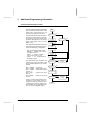
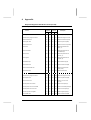
TSX SCM 21.6 Channel 1 - Uni-Telway Bus - User’s Manual
Section
Sub-section
1. Presentation
1.1 General
2
1.2 PLC - Monitor 77 or XBT
4
1.3 PLC - Sensors and Actuators
5
1.4 PLC - PLC
6
2. Implementation
3. Additional Programming
Information
4. Appendix
Page
2.1 Description and Connection
7
2.2 Configuration
9
2.3 Checking Communication
13
2.4 PLC - Monitor 77 or XBT
15
2.5 Using a Text Block
17
2.6 PLC - Sensors and Actuators
22
2.7 PLC - PLC
23
2.8 Limits to Operation
41
2.9 Communication via Telway 7
43
3.1 Broadcast Messages
46
3.2 Events
47
3.3 Discrete I/O Bits and Register Words
50
3.4 Read Object Request
53
3.5 Communication Example
56
4.1 Performance
72
4.2 Module Versions
73
4.3 Requests Supported by
TSX Series 7 PLCs
74
4.4 Standard Requests
76
4.5 Specific Requests
80
4.6 SCA 6 Adapter
103
4.7 Exchange Possibilities
105
4.8 Simultaneous Use of Channels 0 and 1
106
4.9 Exchange Errors
107
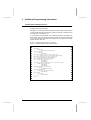
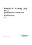
Presentation
This manual complements the Uni-Telway Reference Manual, TSX D 24004F
It is designed to assist the user in implementing and programming channel 1 Qf TSX SCM 21.6 serial
communication modules in the TSX Series 7 family of modular PLCs:
. V3: TSX 47-20/47-30, TSX 67-20, TSX 87-30,
. Model 40: TSX 47-40/67-40/87-40/107-40.
There is a similar manual (TSX D 24007 F) for use with TSX 17-20 Micro-PLCs.
Both channels of a TSX SCM 21.6 module may be used simultaneously with Channel 0 running in character
string mode and Channel 1 supporting the Uni-Telway master or slave protocol. When using both channels
in an application, the information given in Appendix 4.8 should be taken into account.
1
1
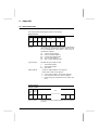
Presentation
1.1 General
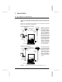
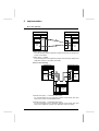
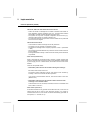
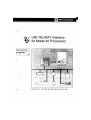
Uni-Telway
The Uni-Telway industrial bus is the standard means of communication between
Telemecanique’s control devices including: PLCs, operator dialog terminals,
variable speed drives, numerical controls, weighing indicators.
Uni-Telway can also simplify communication with devices from other vendors,
such as supervision and control computers.
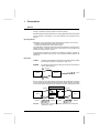
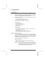
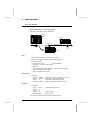
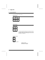
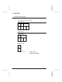
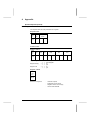
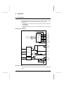
Uni-Telway can be used for two types of application:
. Control and surveillance of system devices by PLC:
Devices such as ATV5 variable speed drives, LT8 protection relays, ASN
specialized couplers, numerical controls.
ALTIVAR 45
ATV 45
Variable
speed
drive
XGS
On
On
L1
L2
DEF1
DEF2
IN1
IN2
OUT1
OUT2
XGS NUM 760
Inductel Numerical
control
NUM 760
TSX 47-30
UNI-TELWAY
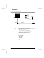
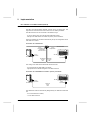
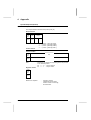
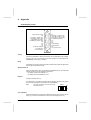
. Man-Machine dialog and supervision:
Devices such as XBT operator dialog terminals or Monitor 77 and the capacity
to support open communications with networks and computers from other
vendors.
TSX 47-30
MONITOR 77
TSX 47-30
CONTRAST DEGAUSS ON.OFF
ON
Reset
OFF
Keyboard
UNI-TELWAY
UNI-TELWAY
Uni-Telway requires:
. 1 Master
This device supervises the data link and checks its operation. It controls the
allocation of bus access time to the various connected devices. This location
comprises a modular TSX Series 7 PLC equipped with a TSX SCM 21.6 serial
communication module.
. 1 to 27 Slaves
2
1
Presentation
General
The services available depend on the connected devices. Services are accessed
through a standard or specific question and answer dialog.
Standard requests are described in the Uni-Telway Reference Manual. Requests
that are specific to TSX Series 7 PLCs are described in the Appendix of this
manual.
Operating Modes
Depending on the configuration of its TSX SCM 21.6 module, a PLC can be:
. a Master and support Client and/or Server status,
. a Slave and support Client and/or Server status.
The TSX SCM 21.6 module controls the physical and data link layers of the UniTelway protocol. It performs the routing to and from the PLC processor that
handles Uni-Telway protocol control.
A TSX SCM 21.6 module can act as the Uni-Telway bus master on power-up,
regardless of the status of its host PLC. Communication between devices can
commence.
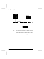
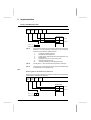
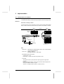
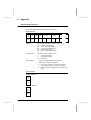
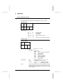
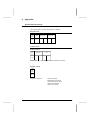
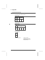
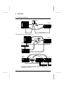
Reminders
CLIENT :
The device that initiates communications. It asks questions (reads),
sends answers (writes) or orders (Run, Stop, etc.).
SERVER :
The device that executes the order sent by the client and sends a
confirm after execution.
1
Request
2
SERVER
CLIENT
3
Action
Confirm
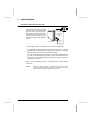
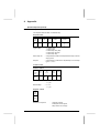
A PLC is a server for its system tasks (programming, adjust, diagnostics). It is also
a Client of other PLCs (and machine tool numerical controls, sensors, actuators)
via the user program text blocks (when sending commands, reading status data).
Request
TSX 7
Request
TXT
SYSTEM
XBT 8
SLAVE
CLIENT
Important :
Confirm
ATV 5
MASTER
SERVER
CLIENT
Confirm
SLAVE
SERVER
Being a Client or a Server is completely separate from the master/slave
relationship on the bus.
3
1
Presentation
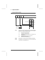
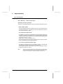
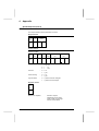
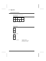
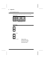
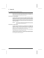
1.2 PLC - Monitor 77 or XBT
MONITOR 77
TSX 87-30
CONTRAST DEGAUSS ON.OFF
ON
Reset
OFF
Keyboard
TSX SCA 62
Telemecanique
UNI-TELWAY
Telemecanique
Telemecanique
XBT B8
PLC
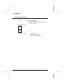
The TSX SCM 21.6 module is the data link master. The PLC
system is a server that answers requests from Monitor 77 and XBT
terminals.
Monitor 77 A slave with client status. It requests information from the PLC to
control the database of TSX Series 7 objects according to the
application description that it is given.
XBT
4
A slave with client or server status.
As a client it can be used to adjust TSX Series 7 PLCs (adjust bits,
words, function blocks, etc.).
As a server it can display messages received, etc.
1
Presentation
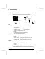
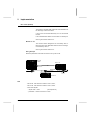
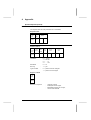
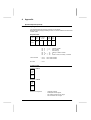
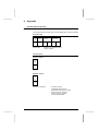
1.3 PLC - Sensors and Actuators
TSX 87-30
ALTIVAR 45
ATV 45
Variable
Speed
Drive
VW3 A45 103
Coupler
Télémécanique
TSX SCA 60
TSX SCA 50
TSX SCA 62
UNI-TELWAY
Telemecanique
Telemecanique
PLC
The TSX SCM 21.6 module is the data link master. The application
program, via a text block is a client that can:
.
.
.
.
.
.
ATV 45
start and stop the ATV 45,
set the acceleration or deceleration slopes,
indicate a direction of motion (forward or reverse),
display a velocity instruction,
request information (status, reading values),
etc.
A slave with server status. It can provide the PLC with various
types of information:
.
.
.
.
.
mains voltage,
stator current,
rotation frequency,
thermal status,
etc.
5
1
Presentation
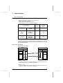
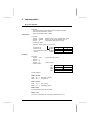
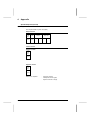
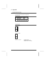
1.4 PLC - PLC
TSX 87-30
TSX 47-30
UNI-TELWAY
TSX SCA 62
Telemecanique
TSX 17 ACC5
PLCs
Telemecanique
Telemecanique
TSX 17-20
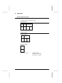
In the configuration illustrated above, the TSX SCM 21.6 module in
the TSX 87-30 PLC is the data link master.
The TSX 17-20 PLC and the TSX SCM 21.6 module in the TSX 4730 PLC are slaves.
Each PLC is a client via its application program and a server via
its system.
6
2
Implementation
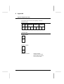
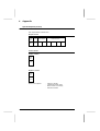
2.1 Description and Connection
Description
TSX SCM 21.6 Serial Communication Modules are intelligent modules that
comprise two fully independent asynchronous serial links. They use the same
hardware as TSX SCM 20 and TSX SCM 22 modules.
The following functions are available on each channel:
. channel 0 :
. channel 1 :
- Half-duplex character string,
- Uni-Telway master protocol,
- Uni-Telway slave protocol.
The transmission function and characteristics of each channel are set when the
module is configured.
Channel 1 can start-up on its configuration by default (Uni-Telway master or
slave).
Only the Uni-Telway master and slave protocols are described in this manual. For
information on character mode operation refer to the TSX SCM 20/21/22
character mode user’s manual (TSX D23 004E).
Connection at the PLC End
The TSX SCM 21.6 module is a standard sized module that operates in a locations
reserved for intelligent I/O modules. Refer to the appropriate PLC installation
manual for further information.
The standard factory coded locating devices prevent any risk of error when
installing or changing a module.
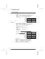
Reminder : Depending on the type of PLC selected, configuration codes are:
PLC
Hardware Code
Software Code
TSX 47-20
69
63
TSX 67/87/47-30
697
697
Number of Modules
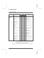
The table below lists the number of TSX SCM 21.6 modules running either UniTelway master or slave protocols that can be installed in TSX Series 7 PLCs.
PLC
Software version
Number of modules
TSX 47-20
V4
1
TSX 47-30/67-20
V3
2
TSX 87-30
V3
4
Prior versions of these PLCs do not support Uni-Telway.
7
2
Implementation
Description and Connection (Cont'd)
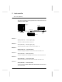
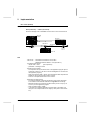
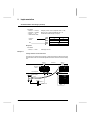
Connection to the Bus
A TSX SCM 21.6 module is connected
to the Uni-Telway bus via a TSX CSB
015 cable and a TSX SCA 62 Subscriber Socket. This cable is fitted with
a 25-pin male sub-D connector on the
TSX SCM 21.6 end and with a 15-pin
male sub-D connector on the TSX SCA
62 end.
Sub D 15-pin
Male
TSX SCM
20
OK
3
Ch0
Telemecanique
F
TSC SCA 62
Y-Junction Box
TSX CBS 015
1.5 meter
5
Ch1
TSX SCM 21.6
Sub D 25-pin
Male
In certain special cases, it is possible to connect the module differently:
. as a dedicated Uni-Telway data link (TSX SCM 21.6) but using a specific
physical interface cable (for example a special point to point TSX 7 - XBT cable
removing the need for TSX SCA 62 Subscriber Sockets).
. with a non-standard physical interface (RS-232C) used as a dedicated data link
(e.g. TSX 7s connected together by modem,). In this case the data link is not
a Uni-Telway bus but a specific data link using the Uni-TE protocol (as with a
TSX SCM 2111 module).
Refer to the pin arrangement given in the Appendix when making specific
connections.
Caution :
8
Whenever a specific connection is used, TSX SCM 21.6 modules cannot
start-up using their configuration by default. It is therefore up to the user
program to send configuration parameters by text blocks.
2
Implementation
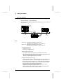
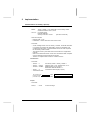
2.2 Configuration
Configuration by Default
TSX SCM 21.6 modules located in slots reserved for intelligent modules in TSX
Series 7 PLCs will start-up with their configuration by default when connected to
a TSX SCA 62 Subscriber Socket via a TSX CSB 015 cable.
Depending on the address set on the micro-switches in the subscriber socket, the
configuration by default is:
. Uni-Telway master if the address is equal to 0,
. Uni-Telway slave if the address is not 0 (1 to 31).
The parameters of the configuration by default are:
Uni-Telway master :
.
.
.
.
poll 31 data link addresses,
binary data flow: 9600 bits/second,
time-out: 30 ms,
8 bytes of events data.
Uni-Telway slave :
.
.
.
.
.
system address set by the subscriber socket connected to the module,
binary data flow: 9600 bits/second,
time-out: 100 ms,
no "client" application address (request - confirm),
no "line monitoring" application address (unsolicited data).
Changing the Standard Configuration
If the standard configuration loaded by default is inadequate (unsuitable data flow
rate, number of stations polled, use of "client" or "line monitoring" application
addresses, etc.) or if the wiring is specific, a new configuration designed
specifically to meet the user’s requirements must be sent by the application
program (sending a parameter table by text block).
This table comprises 5 memory words (10 bytes).
Their coding is entered in:
. Hexadecimal: function, number of polled link addresses, addresses,
. BCD: binary data flow, time out.
Important :
When TSX SCM 21.6 modules are connected to a TSX SCA 62 Subscriber
Socket, the software configuration must have the same settings as the
subscriber socket; function code for Uni-Telway master or slave and UniTelway system address for a Uni-Telway slave. If there is any difference in
the settings, the hardware setting overrides the software.
9
2
Implementation
Configuration (Cont'd)
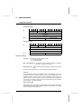
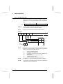
Table Structure
Uni-Telway master
F
Wi
C
B
8
Function (5)
0
0
0
7
4
3
0
Number of link addresses polled
0
(Reserved)
Binary data flow
0
Time out
Wi + 4
0
Size of events data
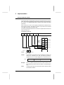
Uni-Telway slave
F
Wi
C
B
8
Function (6)
0
0
0
7
4
3
0
Server system address (Ad0)
0
(Reserved)
0
Binary data flow
Time out
Wi + 4
Line monitoring application address (Ad2)
Client application address (Ad1)
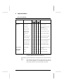
Parameter Meanings
Function :
Specifies the channel operating mode:
. 5 = Uni-Telway master,
. 6 = Uni-Telway slave.
Nbr. of link addresses : 152 addresses max. polled by the master, 27 addresses max. if a TSX 47-20 is master.
Binary data flow : 300, 600, 1200, 2400, 4800, 9600 or 19200 Bits per second
(bps),
All devices connected to the bus must have the same binary data flow.
Time-out :
This indicates the maximum authorized period of time between the end of
message transmission (request, selection, etc.) and acknowledgement by the
destination station. The time value is coded in BCD with a time base of 10
milliseconds (ms). The minimum time is that of the slowest device connected to
the bus and must always at least equal the time required to send 10 characters
on the line (e.g. : 80 ms at 1200 bps).
Size of events data :
Events data is sent to the master on the initiative of a slave station. The size of
data processed by TSX SCM 21.6 modules is 8 bytes max. for the first 32 slaves
on the bus (refer to Sub-section 3.2).
10
2
Implementation
Configuration (Cont'd)
Server system address (Ad0) :
This address is coded in the subscriber socket that the module is connected to.
It allows access to the slave PLC’s system (adjust, diagnostics, program up/
download functions, etc.).
Client application address (Ad1) :
This address is assigned by configuration to the slave module. It enables
messages to be sent to or received from other devices connected to the UniTelway bus, whether they require an answer or not.
Line monitoring application address (Ad2) :
This address is assigned to the slave module by configuration. It enables the
reception of unsolicited data from other devices on the Uni-Telway bus.
When the configuration of a slave PLC is sent and addresses Ad1 or Ad2 are not
required, the corresponding byte in the configuration table must be set to zero.
Writing a Configuration
When the standard configuration is unsuitable for the application, the user must
send a table of new parameters to the module. This new table is defined by internal
words (Wi) or constant words (CWi) and is sent by text block.
Summary of text block parameters :
.
.
.
.
Text block
TXTi,M =
TXTi,C =
TXTi,L =
TXTi, local, CPL, direct or indirect addressing,
module address (rack, slot) and channel nbr. = 01,
configuration write request code : H’0040',
length of the table to send to the module : 10 bytes.
These variables can be initialized by program or by configuration if the TSX T607
terminal is running software version V3.0 or higher.
The exchange is started by:
. Setting text block inputs S,I,O to 1 (in Ladder),
. EXCHG TXTi in Literal.
The end of the exchange is indicated by TXTi,D = 1 and TXTi,E = 0.
The confirm TXTi,V (TXTi,R for TSX 47s) can take one of two values:
H’00FE’
correct configuration, accepted and stored by the module,
H’00FD’
incorrect configuration, rejected by the module. The previous
configuration is retained (parameter out of bounds, TXTi,L > 10,...).
11
2
Implementation
Configuration (Cont'd)
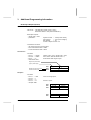
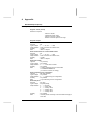
Example
Configuring a station (TSX SCM 21.6 located in rack 2, slot 5) with the following
characteristics:
.
.
.
.
.
Uni-Telway master (function = 5),
poll 15 data link addresses (H’0F’),
binary data flow = 19200 bps,
time-out = 40 ms,
8 events bytes reserved by slaves.
The transmission table located after internal word W100 comprises the following
values:
W100 = H’500F’
W101 = B’0000'
W102 = B’1920' (binary data flow corresponding to 19200 bps),
W103 = B’0004' (40 ms = 4 x 10 ms),
W104 = B’0008'
The transmission table is sent to the module by text block TXT2.
The text block parameters are initialized by configuration:
CONFIGURATION : TEXT
NUMBER OF TEXT BLOCKS
N
TXTi NETWORK TYPE ADDR ADDR
LOCAL
MODE BUFFER
0
LOCAL
CPL
DIR
1
LOCAL
CPL
DIR
2
LOCAL
CPL
DIR
W100
:
3
RECEPT
LENGTH
0
0
0
A
T
M
L
H'00FF'
H'00FF'
H'2501'
0
0
10
C
H'0000'
H'0000'
H'0040'
Loading of the module configuration by the application program is triggered by
EXCHG TXT2 if the program is in Literal or by setting inputs S,I,O in Ladder
language.
12
2
Implementation
2.3 Checking Communication
Once the configurations of the various TSX SCM 21.6 modules are loaded, the
user has various ways of checking performance, such as:
. the register words of the various modules,
. the "read station status" request,
. the TSX TS4 310 diagnostics cartridge that checks which devices are connected
to the bus, identifies the stations and performs complete bus diagnostics.
Register Words
The following register word bits are significant when set to 1 and indicate:
1) master PLC
.
.
.
.
IWxy,0,3
IWxy,0,4
IWxy,0,B
IWxy,0,C
module ready,
general fault,
no channels configured,
module in Run,
. IWxy,3,0
one or more data link address do not reply
2) slave PLC
.
.
.
.
IWxy,0,3
IWxy,0,4
IWxy,0,B
IWxy,0,C
module ready,
general fault,
no channels configured,
module is in Run,
.
.
.
.
IWxy,3,0
IWxy,3,1
IWxy,3,2
IWxy,3,3
no polling on the line,
address Ad0 was not polled,
address Ad1 was not polled or is not configured,
address Ad2 was not polled or is not configured.
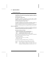
Station Status Read Request
When master PLC bit IWxy,3,0 is set to 1, bus status can be determined using the
"read station status" request (request code A3).
This request is sent to channel 1 of the data link master module:
Example :
MASTER
SLAVES
Link
address 1
Link
address 2
Link
address 3
Link
address 4
13
2
Implementation
Checking Communication (Cont'd)
Transmission
This request is sent by master PLC text block TXT8. The master module is located
in rack 0, slot 5 and the various parameters are:
. TXT8,M = H’0501' rack 0, slot 5, channel 01,
. TXT8,C = H’07A3' category code H’07', request code H’A3',
. TXT8,L = 0
no transmission table.
Depending on the language used, request transmission is triggered by the
command EXCHG TXT8 or by setting inputs S,I and O of text block TXT8 to 1.
Reception
The answer code is given by parameter TXT8,V:
. TXT8,V = H’D3' for correct exchange,
. TXT8,V = H’FD’ for incorrect exchange.
The reception table of text block TXT8 comprises:
. the number of stations controlled by the module (152 max. = H’98'),
. the status of each station, indicated by a succession of 152 bits (19 bytes),
where the first bit gives the status of station 1, the second of station 2, and so
on.
- bit x = 0
- bit y = 1
station x disconnected,
station y connected,
Once the text block exchange is complete, the reception table comprises the
following parameters:
Wi = H’0998' ; Wi+1 = H’0000' ; Wi+2 = H’0000' ; ...... Wi+9 = H’0000'.
The least significant byte gives the number of stations controlled (98),
The most significant byte indicates whether stations are connected or not.
H’09' = L’1001' :
Note :
stations 1 and 4 are connected,
stations 2 and 3 are disconnected.
The data link master module always sends back the status of the stations
connected to the network (152 max.) even if they are not all actually present.
However, only those bits corresponding to the controlled stations are
significant. The length of the text block reception table must be set correctly
(10 words). If incorrect, the text block will generate an error during the
exchange.
Diagnostic Cartridge
Register bits and words and the "read station status" request are automatically
controlled by the TSX TS4 310 Adjustment Cartridge. For further information refer
to the TSX T407 Adjustment Cartridge User’s Manual.
14
2
Implementation
2.4 PLC - Monitor 77 or XBT Terminal
Monitor 77
Monitor 77, the TSX Series 7 supervision system can be connected to the UniTelway bus. The asynchronous serial link used conforms to Uni-Telway standards.
Monitor 77 is connected to the Uni-Telway bus via a TSX SCA 62 Subscriber
Socket, or via a TSX SCA 72 Adapter Box.
TSX SCA 62 connection principles
TSX SCA 62
Subscriber Socket
Telemecanique
TSX M77 CB2 015
1.5 meter
cable
TSX SCM 21.6
20
Telemecanique
Sub D
15-pin Male
TSX CSB 015
1.5 meter
cable
TSX SCM
TSX SCA 62
Subscriber Socket
UNI-TELWAY Bus
F
OK
20m max.
3
Ch0
5
Ch1
Sub D
25-pin Male
CONTRAST DEGAUSS ON.OFF
ON
Reset
OFF
Keyboard
Sub D
15-pin Male
MONITOR 77
Monitor 77 does not
isolate signals, therefore the bus length is
restricted to 20 meters.
In practice, this means
that most installations
will be restricted to a
point-to-point link between Monitor 77 and
the PLC. The coding of
the TSX SCA 62 Subscriber Socket should
be 0 for the link with the
PLC. No code is required on the Monitor
77 side as the address
is defined in the Monitor 77 configuration.
TSX SCA 72 Adapter Box.
UNI-TELWAY Bus
TSX SCA 62
TSX CSB 015
1.5 meter
cable
Sub D
15-pin Male
TSX M77 CB6 015
1.5 meter
cable
TSX SCM 21.6
TSX SCM
20
Télémécanic
TSX SCA 72
Telemecanique
F
OK
3
Ch0
5
If the distance between
the supervisor and the
PLC is greater than 20
meters, it is recommended that the appropriate channel be fitted
with a TSX RCA 1
Adapter connected to
the TSX SCA 72 Adapter Box.
Ch1
Sub D
25-pin Male
CONTRAST DEGAUSS ON.OFF
ON
Reset
Keyboard
OFF
Sub D
15-pin Male
MONITOR 77
Important :
Monitor 77 uses the first 15 Uni-Telway link addresses (1 to 15).
15
2
Implementation
PLC - Monitor 77 or XBT Terminal (Cont'd)
XBT
The XBT man-machine dialog terminal connects to the Uni-Telway bus. The
asynchronous serial link that is used conforms to Uni-Telway standards:
The XBT 8 terminal can be connected in two different ways:
. to the Uni-Telway bus via a TSX SCA 62 Subscriber Socket,
. directly to the TSX SCM 21.6 module for point to point connections.
These two methods of connection automatically set-up the configuration of the
TSX SCM 21.6 module.
Connection to a TSX SCA 62 :
TSX SCM
20
F
OK
3
Sub D
15-pin Male
TSX SCA 62
Subscriber Socket
Sub D
15-pin Male
Telemecanique
UNI-TELWAY Bus
Ch0
Sub D
25-pin Male
5
Ch1
XBT B8
Sub D
25-pin Male
TSX SCM 21.6
TSX CSB 015
1.5 meter
cable
XBT Z908
1.8 meter
cable
The coding of the TSX SCA 62 Subscriber Socket must be:
. 0 for the link with the TSX SCM 21.6 module,
. appropriate for the address assigned to the XBT 8 terminal.
Connection to a TSX SCM 21.6 module in point to point mode :
TSX SCM
20
F
OK
3
Ch0
5
Ch1
TSX SCM 21.6
XBT B8
Sub D
25-pin Male
XBT Z918
5 meter
cable
Sub D
25-pin Male
The addresses used are automatically designated by the XBT Z918 cable and
are:
. 0 for a TSX SCM 21.6 module,
. 1 for an XBT 8 terminal.
16
2
Implementation
2.5 Using a Text Block
Reminders
Communication is essentially performed via a question and answer dialog
referred to as Request/Confirm.
Request structure
A
.
.
.
request comprises:
the request code (one byte),
the category code (one byte),
parameters and/or data (126 bytes max. or limited to 30 bytes with a TSX 4720).
Request Category
Code
Code
Data
Confirm structure
A confirm comprises:
. the confirm code (one byte),
. parameters and/or data (127 bytes max. or limited to 31 bytes with a TSX 4720).
Report
Data
Master PLC
The request is sent by the application program from the Client master PLC by text
block. This text block (set for EXCHG or with S, I and O at 1 depending on the
language, for requests that require a confirm) must comprise all request parameters.
The existing relationship between the structure of a request/confirm and the text
block parameters are:
Transmission
Request Category
Code
Code
Byte
Byte
Word
Transmission Table
1st word
2nd word
TxTi,C = H’ 07
Example :
'
Write object request = H'37'
TxTi,C = H’0737'
Note :
The category code must always take the value H’07'.
17
2
Implementation
Using a Text Block (Cont'd)
TXTi,M
Comprises the physical location of the TSX SCM 21.6 module in the
master PLC, followed by the data link address (encoded in
hexadecimal) of the exchange destination slave increased by
H’64'.
TxTi,M =
Rack Nbr.
Slot
Destination link address + H’64'
Example :
TXTi,M = H’0365' corresponds to the master module located in rack
0, slot 3 addressing the slave at data link address 1.
TXTi,L
Comprises the length of the transmission table (in bytes).
Reception
Report
Byte
Byte
Word
Reception Table
1st word
2nd word
TxTi,V = H’ 00
'
TxTi,R for TSX 47-20
TXTi,S
Comprises the number of bytes received in the text block reception
table when a correct exchange is performed. If the exchange is
incorrect, TXTi,S takes the following values:
1
2
3
4
5
6
10
18
:
:
:
:
:
:
:
exchange cancelled by Reset,
transmission table length error,
exchange error (see Sub-section 2.8 and Appendix 4.8),
module failure,
parameter errors or too many active TXTs,
message received too long,
incorrect addressing of the indirect text block.
TXTi,D
This bit goes to 1 when the text block completes its exchange.
TXTi,E
This bit goes to 1 if an exchange error occurs (for further details refer
to Sub-section 2.8 and Appendix 4.8).
2
Implementation
Using a Text Block (Cont'd)
Slave PLC
The request is sent by the application program from the Client slave PLC via a text
block. This text block (depending on the language selected, is set for EXCHG or
S, I and O at 1, for requests that require a confirm) must comprise all request
parameters.
When a slave PLC is a client, it must specify the address of the destination entity
when sending a request. This address is coded in 5 bytes and must be included
at the start of text block transmission table.
The existing relationship between the structure of a request/confirm and the text
block parameters are:
Transmission from Ad1
Request Category
Code
Code
Byte
Byte
Word
Transmission Table
Destination
Address
Network
Nbr.
0
1st word
Gate
Nbr.
Station
Nbr.
2nd word
Channel Module
Nbr.
Addr.
3rd word
4th word
5th word
TxTi,C = H’ 07
Example :
TXTi,M
'
Read timer request = H’09'
TxTi,C = H’0709'
Comprises the physical location of the TSX SCM 21.6 module in the
master PLC, followed by the data link address (encoded in
hexadecimal) of the exchange origin slave incremented by H’64'.
TxTi,M =
Rack Nbr.
Slot
Sender link address + H’64'
Example :
TXTi,M = H’066B’ corresponds to a slave module located in rack 0,
slot 6 addressing a slave at data link address 7 (corresponding to
Ad1).
TXTi,L
Comprises the length of the transmission table (in bytes) including
the destination address.
19
2
Implementation
Using a Text Block (Cont'd)
Reception on Ad0
Report
Byte
Word
Byte
Reception Table
1st word
2nd word
TxTi,V = H’ 00
'
TxTi,R for TSX 47-20
TXTi,S
Comprises the number of bytes received in the text block reception
table when a correct exchange is performed. If the exchange is
incorrect, TXTi,S takes the following values:
1
2
3
4
5
6
10
:
:
:
:
:
:
:
exchange cancelled by Reset,
transmission table length error,
exchange error (see Sub-section 2.8 and Appendix 4.8),
module failure,
parameter errors or too many active TXTs,
message received too long,
incorrect addressing of the indirect text block.
TXTi,D
This bit goes to 1 when the text block completes its exchange.
TXTi,E
This bit goes to 1 if an exchange error occurs (for further details refer
to Sub-section 2.8 and Appendix 4.8).
Note
Receiving data via the master PLC’s text block
When a slave PLC sends a request to the master PLC’s text block, the parameters
received by the destination text block are:
Request Category
Code
Code
Byte
Byte
Reception Table
1st word
2nd word
TxTi,V = H’ 00
TxTi,R for TSX 47-20
20
'
2
Implementation
Using a Text Block (Cont'd)
Reception on Ad2 (text block in Input)
Request Category
Code
Code
Byte
Byte
Reception Table
Network
Nbr.
Sender Address
1st word
Station
Nbr.
2nd word
Channel Module
Nbr.
Addr.
3rd word
Gate
Nbr.
4th word
TxTi,V = H’ 00
'
TxTi,R for TSX 47-20
TXTi,S
Comprises the number of bytes received in the text block reception
table when a correct exchange takes place. If the exchange is
incorrect, TXTi,S takes the following values:
1
2
3
4
5
6
10
:
:
:
:
:
:
:
exchange cancelled by Reset,
transmission table length error,
exchange error (see Sub-section 2.8 and Appendix 4.8),
module failure,
parameter errors or too many active TXTs,
message received too long,
indirect text block addressing error.
TXTi,D
This bit goes to 1 when the text block completes its exchange.
TXTi,E
This bit goes to 1 if an exchange error occurs (for further details refer
to Sub-section 2.8 and Appendix 4.8).
21
2
Implementation
2.6 PLC - Sensors and Actuators
Example
Reading the velocity reference of an ATV 45 variable speed drive.
ALTIVAR 45
ATV 45
Variable
Speed Drive
VW3 A45 103
Coupler
Télémécanique
TSX 87-30
Master
TSX SCA 62
TSX SCM 21.6
Rack 0,
Slot 3
TSX SCA 60
TSX SCA 50
UNI-TELWAY
Telemecanique
Telemecanique
Data
. ATV 45:
- Velocity reference = W193
- Data link address = 1
(see ATV 45 documentation),
. Read word request :
- request code = H’04'
(see list of references)
- parameter = number of the word to read.
. Text block:
- The request is sent by application text block TXT2.
- Start of the transmission table = W164.
- Start of the reception table = W100.
Transmission
. Text block:
-
TXT2,C = H’0704'
TXT2,M = H’0365'
TXT2,L = 2
Transmission table :
category code = H’07', request code = H’04'
rack 0, slot 3, link address = 1,
length (in bytes) of the transmission table,
W164 = 193 number of the word to read.
Reception
. Text block:
-
TXT2,V = H’34'
TXT2,D = 1
TXT2,E = 0
Transmission table :
correct exchange confirm.
W100 = 400 (velocity reference = 40 Hz).
ATV 45 documentation specifies that the velocity reference is expressed with a
time-base of 0.1 Hz.
22
2
Implementation
2.7 PLC - PLC
Presentation
Dialog between PLCs connected to the Uni-Telway bus uses text blocks. The
transmission text block can send its messages or data to:
. the system gate of the PLC that is the destination of the exchange (access to
all standard and specific requests as described in the Appendix).
. an application program text block (message system access).
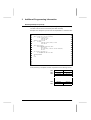
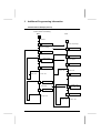
The table below shows all the various possibilities for dialog between a master
PLC and slave PLCs:
MASTER PLC
SLAVE PLC
Text block
System gate
System gate
Text block
Text block
Text block
Text block
Text block
SLAVE PLC
Text block
System gate
Text block
Text block
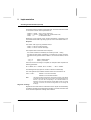
Each of the possibilities listed above will be described in an example corresponding to the bus layout shown below:
TSX 87-30
Master
TSX 47-30
TSX SCA 62
Telemecanique
TSX SCA 62
Ad0 = 1
Ad2 = 2
Telemecanique
UNI-TELWAY Bus
Ad1 not configured
TSX SCA 62
Ad0 = 3
Ad1 = 4
Ad2 = 5
Telemecanique
TSX 47-20
23
2
Implementation
PLC - PLC (Cont'd)
Addressing
3
.
.
.
data link addresses can be assigned to a slave PLC :
Address Ad0 (system address),
Address Ad1 (client application address),
Address Ad2 (line monitoring application address).
Example of
SCM slave
channels
Logical entities
(slave PLC processor)
Uni-Telway
link address
channels
Answers
requests
SYSTEM
67
Ad0
(3 = 67 - 64)
Sends requests
to a server
device on
Uni-Telway
CLIENT
APPLICATION
68
Ad1
(4 = 68 - 64)
Receives the
"Unsolicited
Data" request
LINE
MONITORING
APPLICATION
69
Ad2
(5 = 69 - 64)
Access to the system gate is always available through address Ad0. This address
is coded in the TSX SCA 62. Access to specific client application (Ad1) and line
monitoring (Ad2) addresses are optional. When these addresses are used, they
need to be configured first.
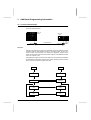
Various Types of Exchange
Master to slave exchange
MASTER
PLC
SLAVE
SCM 21.6
SCM 21.6
System
a
PLC
System
Ad0
Ad1
Appli.
TxTi
b
Ad2
Appli.
TxTj
a) Master —> Ad0
For communication from the master application program (text block) to the
system of the slave PLC (access to PL7 objects).
b) Master —> Ad2
To send messages from the master application program (text block) to the
application program of the slave PLC (text block).
24
2
Implementation
PLC - PLC (Cont'd)
Slave to master exchange
MASTER
PLC
SLAVE
SCM 21.6
SCM 21.6
System
PLC
System
a
Ad0
Ad1
Appli.
TxTi
b
Appli.
TxTj
Ad2
a) Slave (Ad1) —> Master
For communication from the application program of the slave (text block) to the
system of the master.
b) Slave (Ad1) —> Master
To send messages from the application program of the slave (text block) to the
application program of the master (text block).
Slave to slave exchange
SENDER SLAVE
DESTINATION SLAVE
PLC
SCM 21.6
SCM 21.6
System
Appli.
TxTi
System
a
Ad0
PLC
Ad0
Ad1
Ad1
Ad2
b
Ad2
Appli.
TxTj
SCM
21.6
PLC
System
Application
TxTk
MASTER
a) Sender slave (Ad1) —> Destination slave (Ad0)
For communication from the application program of the sender slave (text
block) to the system of the destination slave.
b) Sender slave (Ad1) —> Destination slave (Ad2)
To send messages from the application program of the sender slave (text
block) to the application program of the destination slave (text block).
25
2
Implementation
PLC - PLC (Cont'd)
List of standard and specific services :
Family
Service
Variable
Management
(read)
(*)
Request
Confirm
Description
Hex.
Dec.
Hex.
Dec.
Read a Bit (*)
00
00
30
48
Reads a bit (B).
Read a Word (*)
04
04
34
52
Reads a word (W).
Read Objects (*)
36
54
66
102
Reads objects (bits, words, bit or
word strings ...).
Read a System Bit
01
01
31
49
Reads a system bit (SY).
Read Memory
Image of an I/O Bit
02
02
32
50
Reads the image of an I/O bit.
Read a Constant
Word
05
05
35
53
Reads a constant word (CW).
Read a System
Word
06
06
36
54
Reads a system word (SW).
Read a Common Word
07
07
37
55
Reads a common word (COM).
Read a Timer
09
09
39
57
Reads the parameters of a
timer (T).
Read a Monostable
0A
10
3A
58
Reads the parameters of a
mono-stable (M).
Read a Counter
0B
11
3B
59
Reads the parameters of a
counter (C).
Read a Register
0E
14
3E
62
Reads the parameters of a
register (R).
Read Grafcet Steps
2A
42
5A
90
Reads Grafcet steps (Xi).
Read a Double Word
40
64
70
112
Reads a double word (DW).
Read a Constant
Double Word
41
65
71
113
Reads a double constant word.
Read a Grafcet Step
4B
75
7B
123
Reads a Grafcet step.
Standard requests that are described in detail in the Appendix of the
Uni-Telway Reference Manual, sub-section 5.4.
Only specific requests are described in the Appendix to this manual, sub-section
4.3.
26
2
Implementation
PLC - PLC (Cont'd)
Family
Service
Request
Confirm
Description
Hex.
Dec.
Hex.
Dec.
Write a Bit (*)
10
16
FE
254
Writes a bit (B).
Write a Word (*)
14
20
FE
254
Writes a word (W).
Write Objects (*)
37
55
FE
254
Writes objects (bits, words, bit or
word strings ...).
Write a System Bit
11
17
FE
254
Writes a system bit (SY).
Write the Memory
Image of an I/O Bit
12
18
FE
254
Writes the image of an I/O bit.
Write a System
Word
15
21
FE
254
Writes a system word (SW).
Write a Common Word
16
22
FE
254
Writes a common word (COM).
Write Timer Preset
17
23
FE
254
Writes a timer preset (T).
Write Monostable Preset
18
24
FE
254
Writes a monostable preset (M).
Write Counter Preset
19
25
FE
254
Writes a counter preset (C).
Write Register Input
1A
26
FE
254
Writes a register input (R).
Write a Double Word
46
70
FE
254
Writes a double word (DW).
Unsolicited Data
Unsolicited Data (*)
FC
252
X
X
Operating Mode
Management
RUN (*)
24
36
FE
254
Sets a device to RUN.
STOP (*)
25
37
FE
254
Sets a device to STOP.
Variable
Management
(write)
(*)
Sends data without first receiving
a request.
Standard requests that are described in detail in the Appendix of the
Uni-Telway Reference Manual, sub-section 5.4.
Only specific requests are described in the Appendix to this manual, sub-section
4.3.
Note :
Other standards and specific requests are supported by PLCs. These are
used for specific applications (e.g. programming and diagnostics from
Telemecanique terminals). They are not described in this manual.
27
2
Implementation
PLC - PLC (Cont'd)
Presentation of Examples
The various possibilities for communication between master and slave PLCs are
described in the examples of dialog between devices connected to the UniTelway bus as shown below:
TSX 87-30
Master
TSX 47-30
TSX SCA 62
Telemecanique
TSX SCA 62
Ad0 = 1
A,do = 2
Telemecanique
UNI-TELWAY Bus
Ad1 not configured
TSX SCA 62
Telemecanique
Ad0 = 3
Ad1 = 4
Ad2 = 5
TSX 47-30
Example 1
Master (text block) —> Slave (system gate)
Read TSX 47-20 word W100 by TSX 87-30.
Example 2
Slave (text block) —> Master (system gate)
Read the parameters of TSX 87-30 timer T10 by TSX 47-30.
Example 3
Master (text block) —> Slave (text block)
Send the message "PIN FAULT" from the TSX 87-30 to the TSX 47-30.
Example 4
Slave (text block) —> Master (text block)
Send the message "FAULT STORED" from the TSX 47-30 to the TSX 87-30.
Example 5
Slave (text block) —> Slave (system gate)
Transfer word W10 from the TSX 47-30 to word W54 of the TSX 47-20.
Example 6
Slave (text block) —> Slave (text block)
Send the message "HIGHER THRESHOLD NOT REACHED" from the TSX 4730 to the TSX 47-20.
28
2
Implementation
PLC - PLC (Cont'd)
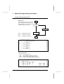
Example 1
Master (text block) —> Slave (system gate)
Read TSX 47-20 word W100 by TSX 87-30.
TSX 87-30
Master
TSX 47-30
TSX SCA 62
Telemecanique
TSX SCA 62
Ad0 = 1
Ad2 = 2
Telemecanique
UNI-TELWAY Bus
Ad1 not configured
TSX SCA 62
Telemecanique
Ad0 = 3
Ad1 = 4
Ad2 = 5
TSX 47-30
Data
. TSX 87-30 : TSX SCM 21.6 located in rack 0, slot 3,
. TSX 47-20 : destination data link address Ad0 (system) = 1.
. Read word request:
- request code = H’04'
(see request list)
- parameter = number of words to read.
. Text block :
- The request is sent by text block TXT1 of the application program,
- start of transmission table = W164,
- start of reception table = W100.
Transmission
. Text block:
-
TXT1,C = H’0704'
TXT1,M = H’0365'
TXT1,L = 2
transmission table :
category code = H’07', request code = H’04'
rack 0, slot 3, data link address = 1,
transmission table length (in bytes),
W164 = 100 number of the word to read.
Reception
. Text block:
-
TXT1,V = H’34'
TXT1,D = 1
TXT1,E = 0
TXT1,S = 2
Reception table
correct exchange confirm.
receive 2 bytes.
W100 = 1500
The content of W100 of the TSX 47-20 is therefore 1500.
29
2
Implementation
PLC - PLC (Cont'd)
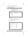
Example 2
Slave (text block) —> Master (system gate)
Addressing principles (reminders)
A slave PLC has 3 data link addresses. They are defined by configuration and are:
. System address (Ad0)
All of the messages received on this address are sent to the system gate of the
exchange destination PLC. This address is required and defined by coding the
TSX SCA 62 Subscriber Socket.
. Client application address (Ad1)
This address is controlled by the application program of the slave (text block).
It enables transmission of the request to any Uni-Telway address (system gate
or text block in the master or slave PLC or in any other device) and the reception
of all related answers or confirms.
Address Ad1 is coded in parameter TXTi,M.
Using this address requires the coding, at the start of the text block transmission
table, of the address of the exchange destination.
. Line monitoring application address (Ad2)
This address is assigned to the slave module for receiving unsolicited data
(request H’FC’) from other devices on the Uni-Telway bus.
The messages received at this address are sent to the application program
through a text block set to receive.
Note :
30
Addresses Ad1 (client application) and Ad2 (line monitoring application) can
only be configured by text block. They are optional, therefore if they are not
required it is not necessary to needlessly lengthen the polling cycle.
2
Implementation
PLC - PLC (Cont'd)
TXTi,M comprises :
. the rack number where the TSX SCM 21.6 slave module (0 to F) is located,
. the location of the module in the rack (0 to 7),
. the data link source address where the exchange originated (data link address
Ad1 incremented by H’64').
Destination address
This is included at the start of the transmission table of the text block that
originated the exchange, in the format shown below:
Wi
network number
0
Wi+1
gate number
station number
Wi+2
channel number
module number
Wi+3
DATA
The following parameters are used:
Network number :
The number of the Telway 7 network on which the destination station is located. It takes a value of:
00 regardless of whether a Telway 7 network is used.
Station number :
The address of the PLC on the Telway 7 network. It takes a
value of:
H’FE’ if there is no Telway 7 network or if a master or slave
of the Uni-Telway bus is being addressed.
Gate number :
The number of the logic gate that is the destination of the
exchange. It takes a value of:
00 : access to the system gate,
05 : access to a TSX SCM 21.6 or more generally to a UniTelway slave connected to one of these modules,
H’10' to H’4F’ : access to text blocks (text block number +
H’10').
Note :
The other values are reserved, they must not be used.
31
2
Implementation
PLC - PLC (Cont'd)
Module location
The location of the TSX SCM module that is the destination of
the exchange. It takes the values:
0 to F for the rack number followed by 0 to 7 for the module
location,
H’FE’ if the destination station is on the same Uni-Telway bus.
00 for a gate number other than 5.
Module ch. nbr.
The channel number assigned to the Uni-Telway slave. It
takes the value of the destination data link of the exchange,
incremented by H’64' or:
00 for a gate number other than 5.
Dialog Example
Read the parameters of the TSX 87-30 timer T10 by TSX 47-30.
TSX 87-30
Master
TSX 47-30
UNI-TELWAY Bus
Telemecanique
TSX SCA 62
Ad0 = 1
Ad2 = 2
Telemecanique
Ad1 not configured
Telemecanique
Ad0 = 3
Ad1 = 4
Ad2 = 5
TSX 47-20
Data
. TSX 87-30 : TSX SCM 21.6 module in rack 0, slot 3,
. TSX 47-30 : TSX SCM 21.6 module in rack 0, slot 6.
. Timer read request:
- request code = H’09'
(see request list)
- parameter = number of the timer to read.
32
TSX SCA 62
2
Implementation
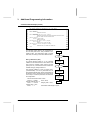
PLC - PLC (Cont'd)
Data (Cont’d)
. Text block:
- The request is sent by text block TXT2 of the application page.
- Start of transmission table = W264,
- Start of the reception table = W200.
Transmission
. Text block:
- TXT2,C = H’0709'
- TXT2,M = H’0668'
- TXT2,L = 8
- transmission table:
Category code = H’07', request code = H’09',
Rack 0, slot 6, data link address Ad1 = 4,
transmission table length (in bytes).
Destination address (master PLC system gate)
Network Nbr./00
W264
00
00
Gate/Device Nbr.
W265
00
FE
Channel Nbr./Module Address
W266
00
Timer Nbr.
W267
00
10
Reception
. Text block:
- TXT2,V = H’39'
- TXT2,D = 1
- TXT2,E = 0
- TXT2,S = 8
- reception table:
correct exchange confirm,
receive 8 bytes.
W200
00
W201
01
02
01
W202
3600
W203
1712
. Answer analysis:
W200 = H’0002'
LSB = 02 —> time base 1 second,
MSB = 00 —> not timed-out.
W201 = H’0101'
LSB = 01 —> timer running,
MSB = 01 —> changeable preset.
W202 = 3600
The configuration preset value is 3600.
W203 = 1712
The current value when the request was processed was 1712.
33
2
Implementation
PLC - PLC (Cont'd)
Example 3
Master (text block) —> Slave (text block)
Send the message "PIN FAULT" from the TSX 87-30 to the TSX 47-30.
TSX 87-30
Master
TSX 47-30
TSX SCA 62
Telemecanique
TSX SCA 62
Ad0 = 1
Ad2 = 2
Telemecanique
UNI-TELWAY Bus
Ad1 not configured
TSX SCA 62
Telemecanique
Ad0 = 3
Ad1 = 4
Ad2 = 5
TSX 47-20
Data
. TSX 87-30 : TSX SCM 21.6 located in rack 0, slot 3,
. TSX 47-30 : TSX SCM 21.6 located in rack 0, slot 6.
destination data link address = Ad2 (link addr. 5).
. Unsolicited data request:
- request code = H’FC’
(see request list)
- parameter = message to send.
. Sender text block (master):
- The request is sent by text block TXT3 of the application program (set-up
as an output with S and O at 1 as there is no answer or confirm),
- start of transmission table = W300,
- there is no reception table as there is no answer.
. Destination text block (slave):
- When a message is sent by a device connected to the Uni-Telway bus, to
a text block of a slave PLC, the slave must know which text block is ready
to receive request H’FC’. To do this the slave PLC must be set-up for
OUTPUT TXTi on initialization (first exchange), then set to await messages by INPUT TXTi.
- Message reception is ensured by text block TXT0 of the application
program,
- Start of reception table = W10. The reception table comprises the
address of the exchange coded in 5 bytes.
34
2
Implementation
PLC - PLC (Cont'd)
Transmission (master)
. Text block:
- TXT3,C = H’07FC’
- TXT3,M = H’0369'
- TXT3,L = 9
- Transmission table:
Category code = H’07', request code = H’FC’,
Rack 0, slot 3, data link address = 5,
transmission table length in bytes.
W300
49 (I)
50 (P)
W301
20 (Space)
4E (N)
W302
41 (A)
46 (F)
W303
4C (L)
55 (U)
W304
54 (T)
Reception
. Text block (in Input) : ("set" reception)
- TXT0,C = H’07FC’ category code = H’07', request code H’FC’,
- TXT0,M = H’0669' rack 0, slot 6, link address Ad2 = 5,
- TXT0,L = 0
no transmission table.
. Text block (data reception)
- TXT0,V = H’FC’
receive request H’FC’,
- TXT0,D = 1
- TXT0,E = 0
- TXT0,S = 15
receive 15 bytes.
- Reception table:
Sender category code
Sender address
W10
00
07
W11
13
FE
W12
00
00
W13
49 (I)
50 (P)
W14
20 (Space)
4E (N)
W15
41 (A)
46 (F)
W16
4C (L)
55 (U)
W17
54 (T)
. Answer analysis:
Network nbr. = H’00' (sender not on a Telway 7 network),
Station nbr. = H’FE’ (sender not on a Telway 7 network),
Gate nbr.
= H’13' (text block 3 - H’10' + text block nbr.),
Module nbr. = H’00' (gate nbr. other than H’05'),
Channel nbr. = H’00' (gate nbr. other than H’05'),
35
2
Implementation
PLC - PLC (Cont'd)
Example 4
Slave (text block) —> Master (text block)
Send the message "FAULT STORED" from the TSX 47-30 to the TSX 87-30.
TSX 87-30
Master
TSX 47-30
TSX SCA 62
Telemecanique
TSX SCA 62
Ad0 = 1
Ad2 = 2
Telemecanique
UNI-TELWAY Bus
Ad1 not configured
TSX SCA 62
Telemecanique
Ad0 = 3
Ad1 = 4
Ad2 = 5
TSX 47-20
Data
. TSX 87-30 : TSX SCM 21.6 located in rack 0, slot 3,
. TSX 47-30 : TSX SCM 21.6 located in rack 0, slot 6.
destination data link address = Ad1 (link addr. 4).
. Unsolicited data request:
- request code = H’FC’
(see request list)
- parameter = message to send.
. Sender text block (slave):
- The request is sent by text block TXT1 of the application program (set as
output with S and O at 1 as there is no acknowledgement or confirm from
the application program),
- Start of transmission table = W100. The transmission table comprises the
address of the exchange sender coded in 5 bytes,
- There is no reception table as there is no answer.
. Destination text block (slave):
- The TXTi,M parameter comprises the location of the master TSX SCM
21.6 module and the data link address that originated the exchange.
- Message reception is ensured by text block TXT5 (set as an input (or S
and I at 1) for the application program.
- Start of reception table = W500.
- In the case of a message destined for the text block of the master, the
first byte in the reception table is the category code (refer to Sub-section
2.5).
36
2
Implementation
PLC - PLC (Cont'd)
Transmission (slave)
. Text block:
-
TXT1,C = H’07FC'
TXT1,M = H’0668'
TXT1,L = 18
Transmission table
Category code = H’07', request code = H’FC’,
Rack 0, slot 6, data link address = 4,
transmission table length (in bytes).
Destination address
Data
W100
00
00
W101
15
FE
W102
00
00
W103
41 (A)
46 (F)
W104
4C (L)
55 (U)
W105
20 (Space)
54 (T)
W106
54 (T)
53 (S)
W107
52 (R)
4F (O)
W108
44 (D)
45 (E)
Reception (master)
. Text block ("set" reception):
- TXT5,C = H’07FC'
- TXT5,M = H’0368'
- TXT5,L = 0
category code = H’07', request code H’FC’,
rack 0, slot 3, data link address Ad1 = 4,
no transmission table.
. Text block (data reception)
- TXT5,V = H’FC’
receive request H’FC’,
- TXT5,D = 1
- TXT5,E = 0
- TXT5,S = 13
receive 13 bytes.
- Reception table:
Sender category code
Date
W500
46 (F)
07
W501
55 (U)
41 (A)
W502
54 (T)
4C (L)
W503
53 (S)
20 (Space)
W504
4F (O)
54 (T)
W505
45 (E)
52 (R)
W506
44 (D)
37
2
Implementation
PLC - PLC (Cont'd)
Example 5
Slave (text block) —> Slave (system gate)
Transfer word W10 from the TSX 47-30 to word W54 of the TSX 47-20:
TSX 87-30
Master
TSX 47-30
UNI-TELWAY Bus
Telemecanique
TSX SCA 62
TSX SCA 62
Ad0 = 1
Ad2 = 2
Telemecanique
Ad1 not configured
TSX SCA 62
Telemecanique
Ad0 = 3
Ad1 = 4
Ad2 = 5
TSX 47-20
Data
. TSX 47-30 : TSX SCM 21.6 located in rack 0, slot 6,
sender data link address = Ad1 (data link address 4).
. TSX 47-20 : destination data link address = system address Ad0 = 1.
. Write word request:
- request code = H’14'
- parameter = number and value of the word to write.
. Text block:
- The request is sent by text block TXT4 of the application program
- Start of transmission table = W400. The transmission table comprises the
address of the exchange sender coded in 5 bytes,
- There is no reception table as there is no answer.
Transmission
. Text block:
-
TXT4,C = H’0714'
TXT4,M = H’0668'
TXT4,L = 10
transmission table:
Destination address
category code = H’07', request code H’14',
rack 0, slot 6, data link address Ad1 = 4,
length (in bytes) of the transmission table,
W400
00
00
W401
05
FE
W402
65
W403
54
Value of word W10
W404
112
Reception
. Text block:
- TXT4,V = H’FE’
38
FE
Number of the word to read
correct exchange.
2
Implementation
PLC - PLC (Cont'd)
Example 6
Slave (text block) —> Slave (text block)
Send the message "HIGHER THRESHOLD REACHED" from the TSX 47-30 to
the TSX 47-20:
TSX 87-30
Master
TSX 47-30
UNI-TELWAY Bus
Telemecanique
TSX SCA 62
TSX SCA 62
Ad0 = 1
Ad2 = 2
Telemecanique
Ad1 not configured
TSX SCA 62
Telemecanique
Ad0 = 3
Ad1 = 4
Ad2 = 5
TSX 47-20
Data
. TSX 47-30 : TSX SCM 21.6 located in rack 0, slot 6,
destination data link address = Ad1 (link addr. 4).
. TSX 47-20 : TSX SCM 21.6 located in rack 0, slot 3.
destination data link address = Ad2 (link addr. 2).
. Unsolicited data request:
- request code = H’FC’,
- parameter = message to send.
. Sender text block (TSX 47-30):
- The request is sent by text block TXT8 of the application program,
- Start of transmission table = W800. The transmission table comprises the
address of the exchange sender coded in 5 bytes,
- There is no reception table as there is no answer.
. Destination text block (TSX 47-20):
- When a message is sent by a device connected to the Uni-Telway bus, to
the text block of a slave PLC, the slave module must know which text
block is ready to receive request H’FC’. This requires that the destination
text block be set-up as OUTPUT TXTi on initialization (first exchange)
and then be set to await messages on INPUT TXTi.
- Message reception is ensured by text block TXT4 set-up to await
reception of the application program (S and I at 1).
- Start of reception table = W200. The transmission table comprises the
address of the exchange sender coded in 5 bytes.
39
2
Implementation
PLC - PLC (Cont'd)
Transmission
. Text block:
-
TXT8,C = H’07FC’
TXT8,M = H’0668'
TXT8,L = 26
Transmission table:
Category code = H’07', request code = H’FC’,
Rack 0, slot 6, data link address Ad1 = 4,
Length of the transmission table in bytes.
Destination address
Data
W800
00
00
W801
05
FE
W802
66
FE
W803
49 (I)
48 (H)
W804
48 (H)
47 (G)
W805
52 (R)
45 (E)
W806
54 (T)
20 (Space)
W807
52 (R)
48 (H)
W808
53 (S)
45 (E)
W809
52 (R)
20 (Space)
W810
41 (A)
45 (E)
W811
48 (H)
43 (C)
W812
44 (D)
45 (E)
Reception
. Text block (S and I at 1): ("set" reception)
- TXT4,C = H’07FC’
- TXT4,M = H’0266'
- TXT4,L = 0
category code = H’07', request code H’FC’,
rack 0, slot 2, data link address Ad2 = 2,
no transmission table.
. Text block (data reception)
-
TXT4,R = H’FC’
TXT4,D = 1
TXT4,E = 0
TXT4,S = 24
reception table:
receive request H’FC’,
receive 24 bytes.
Sender Category Code
Sender address
Data
40
W200
00
07
W201
05
FE
W202
68
FE
W203
49 (I)
48 (H)
W204
48 (H)
47 (G)
W205
52 (R)
45 (E)
W206
54 (T)
20 (Space)
W207
52 (R)
48 (H)
W208
53 (S)
45 (E)
W209
52 (R)
20 (Space)
W210
41 (A)
45 (E)
W211
48 (H)
43 (C)
W212
44 (D)
45 (E)
2
Implementation
2.8 Limits to Operation
Exchanges of messages or data on the Uni-Telway bus are limited by:
.
.
.
.
Exchanges between the module and the processor,
The limits of the master module,
The limits of the slave module,
Flow checking (message loss on power break)
Module - Processor Exchange
. The processors of TSX 47-30, TSX 67-20 and TSX 87-30 PLCs can exchange
with each module (master or slave), a single input message and a single output
message on each cycle of the application program.
. The processor of the TSX 47-20 PLC can exchange an input or an output
message on each cycle of the application program.
Master Module Limits
. The master module can store 3 messages from the Uni-Telway data link until
they are routed to the PLC processor or back onto the Uni-Telway data link. It
can also store 3 messages from the PLC processor.
. When channel 0 is used, the transmission speed of this channel is restricted to
4800 bps.
Slave Module Limits
. When channel 0 is used, the transmission speed of this channel is restricted to
4800 bps.
. System Access (Ad0) :
The module can only control one exchange (request/confirm cycle) with the
system at a time. If a message is received on the line while an exchange is in
progress, it is refused (NACK).
. Client Application Address (Ad1) :
The module can only control one exchange with the application program at a
time. To start another exchange, the first must be completed (reception of a text
block that resets bit D of the text block).
. Line monitoring Application Address (Ad2) :
The module does not restrict communication in line monitoring mode on data
link address Ad2.
41
2
Implementation
Limits to Operation (Cont'd)
. Processor Limits
TSX 47-30, TSX 67-20 and TSX 87-30 PLC Processors
- These can transfer a message from a module to another local module on
each application program message cycle (e.g.: communication between
TSX SCM 21.6 master modules located in the same rack).
- The system can only store 3 requests, irrespective of their source (e.g.:
terminal in adjust mode, Uni-Telway modules, etc.).
- The exchanges between the processor and the module can be performed
even if the PLC is stopped.
TSX 47-20 PLC Processor
- Local module to module exchanges cannot be performed.
- The system can only process one request at a time.
- The maximum message size is 32 bytes (request or confirm + parameters
+ data).
- No exchange is possible between the processor and the module when the
PLC is stopped.
- Exchanges between a Telway 7 network and a Uni-Telway slave module are
not possible.
. Flow control (master PLC):
When a text block set for EXCHG sends a request, it awaits reception and
remains in this state until it receives an answer. If the destination station suffers
a power supply fault or is disconnected, the sender text block will remain
blocked.
There are two possible cases:
- Destination power break or disconnection during the exchange:
Bits TXTi,D and TXTi,E remain at 0.
The master (client) application program must allow for this situation by
including a "time-out" in sender text block operation.
If no answer is received before time-out, then the text block is reset to 0
(RESET TXTi).
- Destination power break or disconnection before the start of the
exchange or non-existent station:
A text block error occurs, bits TXTi,D and TXTi,E are set to 1 and status word
TXTi,S takes a value of 3.
. Flow Control (slave PLC)
As the slave module can only process one text block at a time, it uses a set 10
second time-out that is reset on each exchange request. If no answer is
received before time-out, the sender text block automatically generates an
error (TXTi,E = 1 and TXTi,S = 3).
42
2
Implementation
2.9 Communication via Telway 7
Exchanges between devices connected to the Uni-Telway bus and stations
connected to the Telway 7 network are fully transparent to the Uni-Telway master.
Example 1
Slave PLC to Telway 7 station
A TSX 87-30 slave on the Uni-Telway bus has to set the preset for Monostable
M6 to a value of 1000 in the TSX 47-30 PLC, station 2 of the Telway 7 network.
Station 1
Station 2
TELWAY 7
TSX 47-30
TSX 47-30
Master
TSX SCA 50
Uni-Telway Bus
euqinacemeleT
ALTIVAR 45
Ad2 not configured
Telemecanique
TSX SCA 62
ATV 45
Variable Speed
Drive
Telemecanique
Ad0 = 5
Ad1 = 6
Télémécanique
VW3 A45 103
Coupler
Télémécanique
Address 1
TSX SCA 60
TSX 87-30
Slave
Data
. TSX 87-30 : TSX SCM 21.6 module located in rack 0, slot 3, sender address
= Ad1 (data link address 6).
. TSX 47-30 : Telway 7, station 2.
exchange destination : system gate.
. Monostable preset write request:
- request code = H’18',
- parameters = number and value of the preset to write.
. Text block:
- The request is sent by text block TXT2 (local type) of the application
program,
- Start of transmission table = W50. The transmission table comprises the
destination address coded in 5 bytes.
- There is no reception table as there is no data to receive.
43
2
Implementation
Communication via Telway 7 (Cont'd)
Transmission
. Text block:
- TXT2,C = H’0718'
- TXT2,M = H’036A’
- TXT2,L = 10
- transmission table :
Category code = H’07', Request code = H’18',
Rack 0, slot 3, data link address Ad1 = 6,
transmission table length (in bytes).
Destination
address
Data
W50
00
00
W51
00
02
W52
00
00
W53
6
W54
1000
Reception
. Text block:
- TXT2,V = H’FE’
exchange correct
Example 2
Telway 7 Station 2 to ATV 45 slave
The TSX 47-30, station 2 of the Telway 7 network must send a velocity instruction
value of 35Hz to the ATV 45 variable speed drive that is a slave on the Uni-Telway
bus.
Station 1
Station 2
TELWAY 7
TSX 47-30
TSX 47-30
Master
TSX SCA 50
Uni-Telway Bus
euqinacemeleT
ALTIVAR 45
ATV 45
Variable Speed
Drive
Ad2 not configured
Telemecanique
TSX SCA 62
Telemecanique
Ad0 = 5
Ad1 = 6
Télémécanique
VW3 A45 103
Coupler
Télémécanique
Address 1
TSX SCA 60
44
TSX 87-30
Slave
2
Implementation
Communication via Telway 7 (Cont'd)
Data
. Master :
. ATV 45 :
Telway 7 station 1. The TSX SCM 21.6 Uni-Telway master
module is located in rack 0, slot 6.
Uni-Telway slave,
Data link address 1,
Velocity instruction = W193
(see ATV 45 manual)
. Write word request:
- Request code = H’14',
- Parameters = number and value of the word to write.
. Text block:
- As the message sender is on the Telway 7 network, the sender text block
is a coupler type network text block (NET). Its TXTi,A parameter must
correspond to the Telway 7 network address of the PLC that comprises
the Uni-Telway master module.
- The request is sent by text block TXT6 of the sender PLC’s application
program.
- Start of the transmission table = W100. The transmission table comprises
only the parameters and the data for the request.
- There is no reception table as there is no data to receive.
Transmission
. Text block:
- TXT6,A = 1
- TXT6,C = H’0714'
- TXT6,M = H’0665'
- TXT6,L = 4
- Transmission table:
Nbr. of word to write
Contents of W193
(time base 0.1Hz)
Uni-Telway master = Telway 7 station 1
Category code = H’07', request code = H’14'.
Master location (rack 0, slot 6),
Destination data link address = 1.
Transmission table length (in bytes).
W100
193
W101
350
Reception
. Text block:
TXT6,V
= H’FE’
correct exchange
45
3
Additional Programming Information
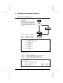
3.1 Broadcast Messages
General
The "broadcast message" service allows a message to be sent from the data link
master device to all of the slave devices connected to the same Uni-Telway bus.
The "broadcast message" service does not support acknowledgements at data
link level nor confirms at application level.
If one of the slaves is not available when this service is used, it will not receive the
message.
Addressing
The data is sent by a coupler type text block with the following characteristics :
TXTi,M
Comprises the sender address and the destinations:
. rack number where the TSX SCM 21.6 master module is located,
. location of the module in the rack,
. the data link address of the exchange destination stations. If they are broadcast
messages, this data link address will be set to H’FF’ by convention.
TXTi,C
Takes the value H’07xy’ where xy corresponds to the request code
of the requested function (e.g. operating mode requests).
Notes :
The processing of this request performed by the destination stations depends on the type of device connected.
In the case of a TSX SCM 21.6 slave module the message is
received on data link address Ad0 (system gate). The message is
sent at data link level without acknowledgement (ACK) from the
destination.
The "unsolicited data" request is not accepted by the system gate
of a slave PLC connected to the bus via a TSX SCM 21.6 module.
46
3
Additional Programming Information
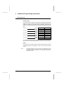
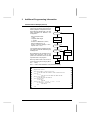
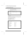
3.2 Events
General
This service enables a slave that supports this function to send data on events to
the TSX SCM 21.6 master module on its own initiative. Slave PLCs connected to
the bus via a TSX SCM 21.6 module do not send events data.
Processing by the Module
This data is sent using simplified addressing, by the "unsolicited data" request that
does not require an answer from the destination. The module receives and stores
the events data received in a buffer. The PLC’s application is informed via the
register field of a change in value. Therefore, each IWxy,4 and IWxy,5 input
register word is assigned a data link address with the following correspondence.
IWxy,4,0 ——> data link address 1,
IWxy,4,1 ——> data link address 2,
IWxy,4,2 ——> data link address 3,
....................................................,
....................................................,
....................................................,
IWxy,5,E ——> data link address 31,
IWxy,5,F ——> data link address 32.
Example
If the events data and data link addresses 4, 8 and 31 have be
changed, the module will set register bits IWxy,4,3, IWxy,4,7 and
IWxy,5,E to 1.
The module processes the events data for data link addresses 1 to 32.
The size of the data sent can be parametered when the TSX SCM 21.6 master
module is configured, but is restricted to 8 bytes max. per data link address (refer
to Sub-section 2.2).
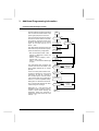
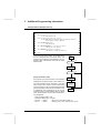
Addressing
Sending events enables the sender to not have to give the destination address.
The data is automatically sent to the master TSX SCM 21.6 module.
Data Acquisition
The data (stored in master module RAM) is read by sending a read events data
request (code H’A8') by text block to channel 1 of the TSX SCM 21.6 module.
It is possible to acquire the events data from a number of devices using the same
request by assigning the value of the input register words IWxy,4 and IWxy,5 to
the first two words of the request sender’s text block. The module then sends back
the number of bytes defined when the TSX SCM 21.6 master module was
configured.
The data is received in the reception table of the sender text block.
47
3
Additional Programming Information
Events (Cont'd)
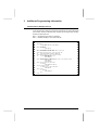
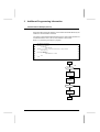
Example
. Data
- The TSX SCM 21.6 module (in rack 0, slot 6) of the TSX 87-30 master PLC
indicates a change of state in the events data for data link addresses 1, 4,
5, 8, 16 and 22 by setting bits IW06,4,0; IW06,4,3; IW06,4,7; IW06,4,F
and IW06,5,5 to 1.
- The size of the events data is configured in the module as 4 bytes for each
data link address.
- The request is sent by text block TXT2 (set-up for EXCHG) of the application
program.
- Start of the exchange table = W264,
- Start of the reception table = W200
. Transmission
- TXT2,M comprises :
The rack number where the TSX SCM 21.6 master module is located,
The location of the module in the rack,
The address of the Uni-Telway channel (01).
TXT2,M = H’0601'
- TXT2,C = read events data request code (H’00A8').
- TXT2,L = comprises the length of the transmission table in bytes.
TXT2,L = 4
- Transmission table
To read the events data received in the buffer of the TSX SCM 21.6 master
module. The first two words in the transmission table should comprise the
values of register words IW06,4 and IW06,5.
48
W264
Content of IW06,4
W265
Content of IW06.5
3
Additional Programming Information
Events (Cont'd)
. Reception
- Reception table
Once the exchange is complete, the text block reception table (located after
W200 with a length of 128 bytes) contains the events data received by the
module. An answer field, the size of which is defined in bytes when the
module is configured, is assigned to each logical channel that sends events
data.
Data station 1
W200
W201
Data station 4
W202
W203
Data station 8
W204
W205
Data station 16
W206
W207
Data station 22
W208
W209
The number of bytes received is indicated by parameter TXT2,S that has a
value of TXT2,S = 20 (4 bytes per logical channel that has sent events data).
Report
The report TXT2,V contains the value of the answer code once the exchange
is complete. (H’D8' if the exchange is correct, if it is incorrect its value is
H’FD’).
Note :
If the data link master is a TSX 47-20 PLC, the maximum size of the
messages is 30 bytes. If the size of the events data is more than 30 bytes,
the application program must allow for it and not request more than 30
characters at a time.
49
3
Additional Programming Information
3.3 Discrete I/O Bits and Register Words
Description
The register interface of the TSX SCM 21.6 modules comprises:
. input registers :
These status words can only be accessed in read. They
describe the operation of the module and each channel.
. output registers : These words are accessible in read and write and enable
acknowledgement and reset commands for the exchanges
on the channels.
Input Register IWxy,0 (ch. 0 and 1)
This status word is common to Uni-Telway master or slave operation contains
data on complete module operation. These bits are significant at 1.
50
Bit
Function
0
1
Not assigned
Not assigned
Description
2
Reset in progress
Message system reset in progress, clears messages in progress on both
channels.
3
Module available
Indicates the end of the self-tests and consequently that the module is
available.
4
General fault
This bit goes to 1 whenever a fault appears. It is the OR routing for bits
5, 6, 7, 8.
5
Blocking fault
A module RAM extension fault.
6
Module fault
A fault that appears when the module serial link self-tests are run every
time the module is powered-up.
7
Application fault
A fault that appears when a request is executed on one of the module
channels:
Parity error in receive, time-out, no echo, incorrect echo, etc.
8
Blocking fault
RAM, EPROM or module internal logic fault. This fault permanently
inhibits the module which must be replaced.
This state is indicated by the F indicator on the front of the module.
9
Module self-test
in progress
Every time it is powered-up, the module runs a serie tesindicated
by this bit.
The module is not available and cannot be programmed while the tests
are in progress.
A
Not assigned
B
Module not
configured
This bit is at 1 when none of the channels are configured. At 1 this bit
indicates that at least one channel has been configured.
C
Module in RUN
mode
Uni-Telway function
D
Reserved
E
F
Not assigned
Not assigned
3
Additional Programming Information
Discrete I/O Bits and Register Words (Cont'd)
Input Register IWxy,0 (ch. 0 and 1)
This status word is common to Uni-Telway master or slave operation. It contains
data on complete module operation. These bits are significant at 1.
Only those bits corresponding to channel 1 (Uni-Telway) are described in detail
below. Refer to the TSX SCM 20/21/22 Half/Full duplex character mode manual
for the corresponding bits for channel 0.
Bit
Function
8
Not assigned
Description
9
Reserved
A
Not assigned
B
Channel 1
configuration
0 if the channel is not configured
1 if the channel is configured
C
D
E
Adapter code
Channel 1
The type of adapter fitted to the channel is
coded in these three bits :
001 = SCA1 adapter (RS-232C - 6 signals)
010 = SCA2 adapter (Current loop)
101 = SCA3 adapter (RS-232 - modem)
011 = SCA4 adapter (RS-422A/RS-485)
000 = SCA5 adapter (RS-232C simplified)
100 = SCA6 adapter (RS-485 Uni-Telway)
110 = SCA7 adapter (AB2 Bus)
111 = No adapter
F
PWF
This bit is common to both channels.
At 1, it indicates a power return but is provided for information only. It must
be reset (by OWxy1,F) to accept another power return.
Master Module Input Register
IWxy,3
Only bit 0 of this word is used. It is significant at 1.
IWxy,3,0 :
indicates that at least one data link address has not replied before
time-out.
IWxy,4
Indicates a change in state in the events data addressed by slave stations with
a data link address from 1 to 16.
IWxy,4,0 : data modification at station address 1,
IWxy,4,1 : data modification at station address 2,
..................................................................................
..................................................................................
IWxy,4,E : data modification at station address 15,
IWxy,4,F : data modification at station address 16.
51
3
Additional Programming Information
Discrete I/O Bits and Register Words (Cont'd)
IWxy,5
Indicates a change in state in the events data addressed by slave stations with
a data link address from 17 to 32.
IWxy,5,0 : data modification at station address 17,
IWxy,5,1 : data modification at station address 18,
..................................................................................
..................................................................................
IWxy,5,E : data modification at station address 31,
IWxy,5,F : data modification at station address 32.
Slave Module Input Register
IWxy,3
Only bits 0 to 3 of this word are used. They are significant at 1.
IWxy,3,0 :
indicates no polling on the line,
IWxy,3,1 :
indicates that address Ad0 is not polled or not configured,
IWxy,3,2 :
indicates that address Ad1 is not polled or not configured,
IWxy,3,3 :
indicates that address Ad2 is not polled or not configured.
Output Register
OWxy,0
Only bit 2 of this word is used. Setting this bit to 1 resets the message system and
blocks control of both module channels, whether they are master or slave units.
This bit is active at 1 and must be reset after use.
Other Register Words
The other register words are not used.
Discrete I/O Bit
The SCA6 (RS-485 Uni-Telway) adapter does not have transmission control
signals. The transmission validation signals used in RS-485 are used to switch the
transmitter to high impedance in a user transparent manner.
For information on the other adapters (SCA1 to SCA5) used on channel 0, refer
to the TSX SCM 20/21/22 Half/Full Duplex Character Mode Manual.
52
3
Additional Programming Information
3.4 Read Object Request
Reminders
This standard request allows read access to simple data objects (words, word
strings, etc.).
The structure of this request is detailed in the Appendix.
When this request is sent, the user must specify the parameters of the sender text
block (TXTi,C; TXTi,M; TXTi,L, etc.) and the transmission table. This comprises
the following parameters:
.
.
.
.
the
the
the
the
segment that the request is addressed to,
type of data object to read,
address of the first object to read,
number of objects to read.
As soon as it finishes processing a request received, a destination station will
send back a message giving the type of object read, followed by the requested
data.
The reception table of the sender text block has the following structure, when
reading words for example:
Wi
1st LSB
Wi + 1
2nd LSB
Type of object
1st MSB
Wi + 2
3rd LSB
2nd MSB
Wi + 3
etc ...
3rd MSB
The data received is therefore shifted by one byte and encoded in two successive
words.
Important
The application program must therefore take into account this shift when
processing the data received. This can be done for example by performing
successive shifts.
Example
Reading a 20 word table (located after address W50) by a TSX 87-30 from a TSX
47-30 slave:
TSX 87-30
Master
TSX 47-30
Slave
Ad0 = 3
Ad1 = 4
Ad2 = 5
UNI-TELWAY Bus
TSX SCA
62
Telemecanique
TSX SCA 62
Telemecanique
53
3
Additional Programming Information
Read Object Request (Cont'd)
Data
. TSX 87-30 : TSX SCM 21.6 module in rack 0, slot 3,
. TSX 47-30 : TSX SCM 21.6 module in rack 0, slot 6,
destination address = Ad0 (data link address 3).
. Read object request:
- request code = H’36'
- parameters :
segment number
type of object
start address
number of objects
= H’68' (internal words),
= H’07' (16-bit integers),
= 50,
to read = 20.
. Transmission text block:
- the request is sent by text block TXT1,
- start of transmission table = W264,
- end of transmission table = W200.
Transmission
. Text block:
-
TXT1,C = H’0736'
TXT1,M = H’0667'
TXT1,L = 6
transmission table:
category code = H’07', request code = H’36',
rack 0, slot 6, data link address Ad0 = 3,
Transmission table length in bytes.
Segment 68 (internal word)
Type 07 (16-bit integer)
W264
07
68
Address of the first word to read
W265
50
Number of words to read
W266
20
Reception
. Text block:
-
TXT1,V = H’66'
TXT1,D = 1
TXT1,E = 0
TXT1,S = 41
reception table:
correct exchange report,
receive 41 bytes.
W200
W50 LSB
Type of object
W201
W51 LSB
W50 MSB
W202
...
W51 MSB
W220
W69 LSB
W221
54
...
W69 MSB
3
Additional Programming Information
Read Object Request (Cont'd)
The program given below enables the repositioning of data by successive shifting.
The data is then stored in a word table (from W200 to W263).
Reception error analysis is up to the user who implements it in subroutine SR1:
~<Example of a data repositioning program
!
<B0=1 if answer ok if not error processing
!
IF TXT1,D.[TXT1,V=H’66']
THEN TXT1,D->B0
ELSE CALL SR1
<Number of words received
L1
:IF RE(B0)
THEN TXT1,S->W140:(W140+1)/2->W140
ELSE JUMP L2
<Shift words received
!
WHILE [W140)0]
DO SHL 8(W200(W140))->W141:
W140-1->W142:
SRC 8(W200(W142)), AND H’FF’ OR W141->W200(W140):
DEC W140
<Set the MSB of word W200 to 0
!
IF [W140=0]
THEN W200 AND H’FF’->W200
<PROGRAM CONTINUES
!L2
:
! EOP
Once processing is completed, the data is positioned in the following manner:
W200
00
Type of object
W201
W50 MSB
W50 LSB
W202
W51 MSB
W51 LSB
W220
W68 MSB
W68 LSB
W221
W69 MSB
W69 LSB
55
3
Additional Programming Information
3.5 Communication Example
The program described below is an example of a dialog between PLCs connected
to the bus illustrated below:
TSX 87-30
Master
TSX 47-30
Slave
Ad0 = 1
Ad1 = 2
UNI-TELWAY Bus
TSX SCA 62
Telemecanique
TSX SCA 62
Telemecanique
Ad2 = 3
Principles
Transfer of word W100 from the master application program to W500 of the slave
application program and display its output on an output module. As soon as a
correct confirm is received, from the request, the application program of the
master will increment word W100 and transfer it again to word W500 of the slave
and so on to W100 = 255.
The application program of the slave then takes over and transfers word W200 to
word W1000 of the application program of the master, applying the same principle
with incrementing to 255 then restart from 255.
56
Master
Slave
Configuration
Configuration
Initialization
Initialization
Send
data
Receive
data
Receive
data
Send
data
3
Additional Programming Information
Communication Example (Cont'd)
The Grafcet diagram shown below is used to provide a graphic illustration of the
various phases of the dialog :
Master
Slave
0
initialization
1
0
send ready message
receive ready message
receive yes message
2
send yes message
1
0 ’ W100
=1
=1
2
await reception
transfer content
W100->slave W500
3
receive W100
confirm OK
4
3
display W500
INC W100
W500 ≤ 255
W100 ≤ 255
W500 > 255
W100 > 255
4
0 ’ W200
=1
5
await reception
receive W200
6
5
display W1000
confirm OK
6
W1000 ≤ 255
transfer content
W200->master W1000
INC W200
W1000 > 255
W200 ≤ 255
W200 > 255
57
3
Additional Programming Information
Communication Example (Cont'd)
Master PLC
Master Task
Start
The master task controls transmission
of the configuration on channel 1 of the
module located in rack 0 slot 6 and
enables dialog on this channel.
YES
Power-up
NO
SR4 Send configuration
Authorize dialog
B30 = 1 : initialization performed
SR1
SR2
SR3
B60 = 1 : reception in progress
B40 = 1 : transmission in progress
End
<Init SCM (ch.1) on power-up
!
IF SY0+SY1
THEN RESET B100:0->W0[1200]
<SCM21 ch.1 configuration if module available
!
IF NOT B100.IW6,0,3
THEN CALL SR4
<Call initialization subroutine
!
IF B100.NOT B30
THEN CALL SR1
<Call transmission subroutine
!
IF B30.NOT B60
THEN CALL SR2
<Call reception subroutine
!
IF B30.NOT B40
THEN CALL SR3
! EOP
Text block definition
.
.
.
.
TXT0
TXT1
TXT2
TXT3
—> send configuration,
—> send "READY" message to the slave,
—> receive "YES" message from the slave,
—> send the "Write Word" request to the slave.
CONFIGURATION : TEXT
NUMBER OF TEXT BLOCKS
TXTi NETWORK
LOCAL
0
LOCAL
1
LOCAL
2
LOCAL
3
LOCAL
4
LOCAL
58
TYPE
CPL
CPL
CPL
CPL
CPL
ADDR
MODE
DIR
DIR
DIR
DIR
DIR
N
ADDR
BUFFER
CW0
CW10
W10
W20
:
5
RECEPT
LENGTH
0
0
4
0
0
A
T
M
H'0601'
H'0667'
H'0666'
H'0665'
H'00FF'
L
10
4
0
4
0
C
H'0040'
H'07FC'
H'07FC'
H'0714'
H'0000'
3
Additional Programming Information
Communication Example (Cont'd)
Timer definitions
T0 ——> time-out for sending the configuration,
T1 ——> time-out between sending the "Ready" message and receiving
a "YES" answer.
T2 ——> time-out that checks the status of the text blocks in the event of a
power break or device disconnection.
CONFIGURATION : TIMERS
TIMERS
NUMBER / MAX :
8/128
+-------------------------+-------------------------+--------------------------+
! NO PRST M TB
MNEMONIC! NO PRST M TB
MNEMONIC! NO PRST M TB
MNEMONIC !
!-------------------------+-------------------------+--------------------------!
! 0
25 Y100ms
!
!
!
! 1
50 Y100ms
!
!
!
! 2
20 Y100ms
!
!
!
! 3 9999 Y 1mn
!
!
!
! 4 9999 Y 1mn
!
!
!
! 5 9999 Y 1mn
!
!
!
Constant words
The configuration parameters are defined in constant words CW0 to CW4. The
message "READY" is defined from CW10 to CW11:
CW0 : Uni-Telway master and sample 3 data link addresses,
CW2 : Transmission speed 9600 bps.
CW3 : 40ms time-out.
CONFIGURATION : CONSTANT WORDS
CW NB CONFIGURED
CONSTANT
CW0
CW1
CW2
CW3
CW4
CW5
CW6
CW7
CW8
CW9
CW10
CW11
CW12
CW13
VALUE
=H'5003'
=0
=B'9600'
=B'0040'
=0
=0
=0
=0
=0
=0
=M'PR'
=M'ET'
=0
=0
:
128
CONSTANT
CW16
CW17
CW18
CW19
CW20
CW21
CW22
CW23
CW24
CW25
CW26
CW27
CW28
CW29
VALUE
=0
=0
=0
=0
=0
=0
=0
=0
=0
=0
=0
=0
=0
=0
59
3
Additional Programming Information
Communication Example (Cont'd)
Configuration (SR4)
<SR4 CONTROLS SENDING THE CONFIGURATION OF CH.1 SCM21 MODULE
!
<Module failure?
!
IF IW6,0,8
THEN RESET B100:RET
<Send configuration data with 2.5 sec. time-out
!
IF NOT B101
THEN RESET TXT0;RESET TXT1;RESET TXT2;RESET TXT3;EXCHG TXT0;
SET B101;PRESET TO;START TO;RESET B102
<Positive confirm?
!
IF TXT0,D.[TXT0,V=H'FE']
THEN SET B100;RET
<No answer from the channel, reset in progress
!
IF TO,D.NOT B102
THEN SET 0W6,0,2;SET B102;RET
<End channel reset and new configuration attempt
!
IF B102
THEN RESET 0W6,0,2;RESET B101;RESET B102
! EOP
For operating safety reasons, the configuration is
sent on each power return. This procedure is controlled by SR4. The configuration table is located
after CW0, according to the values defined below:
Start
Module
Failure
YES
NO
Dialog initialization (SR1)
On request (setting bit B20 to 1), the message
"READY" is sent to the slave PLC. This device must
then return the message "YES" within 5 seconds
(set by timer T1). This ensures that the master PLC
enables dialog by setting bit B30 to 1.
The message "READY" is sent by request H’FC’
(unsolicited data). It is sent by text block TXT1 to
slave data link address Ad2. As this request does not
send back a confirm, text block TXT1 must be set-up
as an Output. Text block parameters are defined in
the configuration:
Send
Configuration
Report
OK
NO
Reset
Current Request
Prepare to
Send Configuration
Again
. start of transmission table: CW10
. TXT1,M = H’0667'
rack 0, slot 6,
End
data link address Ad2 = 3,
. TXT1,C = H’07FC’
category code = H’07',
request code = H’FC’,
. TXT1,L = 4
transmission table length in bytes.
60
YES
3
Additional Programming Information
Communication Example (Cont'd)
Reception of the "YES" message is
ensured by text block TXT2 set-up as
INPUT (reception of request H’FC’ from
slave data link address Ad1). The text
block parameters are defined in the
configuration:
Start
Power-up
NO
YES
. start of reception table
= W10,
. reception table length
= 4 bytes,
. TXT2,M = H’0666' rack 0, slot 6,
data link address Ad1 = 6,
. TXT2,C = H’07FC’ category = H’07',
request code = H’FC’.
The reception table comprises the category code of the sender followed by the
message sent.
B10 enables the user to detect a transmission fault (time-out). This is only
present for information and is not used
anywhere else in the program.
B22 only allows TXT2 to be set as an
Input once during an exchange ("READY" ... "YES").
Send Message
"Ready"
Start timer (T1:5s)
Time-out?
YES
NO
Receive
message "yes"
NO
YES
Set B10 to 1 (fault)
Repeat (B20=1)
Set B30 to 1
(enable dialog)
End
B30 = 1 means that initialization was performed correctly.
~(DIALOG INITIALIZATION
!
<REQUEST DIALOG IF B20=1
!
<Send message "READY" by TXT1 and start timer.
!
IF B20 THEN OUTPUT TXT1;PRESET T1;START T1;RESET B20;SET B22
<Time-out?
!
IF T1,D
THEN SET B10;SET B20;RESET TXT1;RESET TXT2;RET
<Message "YES" received?
!
IF B22 THEN INPUT TXT2;RESET B22
<Check reception table
!
IF NOT TXT2,D
THEN RET
<Category code = H’07' ; O = H'4F' ; U = H'55' ; I = H'49'
!
IF [W10=H'4F07'].[W11=H'4955']
THEN SET B30
!
RET
! EOP
61
3
Additional Programming Information
Communication Example (Cont'd)
Data transmission (SR2)
Subroutine SR2 increments word W100
from 0 to 255 and sends its data to the
system gate (Ad0) of the slave PLC.
Once the request has been sent and as
soon as the correct confirm is received,
the program increments W100 then
sends the "Write Word" (H’14') request
again to the slave and so on to
W100 = 255.....
The "Write Word" request is sent by text
block TXT3 set-up for EXCHG. Its parameters are defined by configuration :
. Start of transmission table = W20,
. TXT3,M = H’0665' rack 0, slot 6, link
address Ad0 = 1,
. TXT3,C = H’0714' category = H’07',
request code = H’14',
. TXT3,L = 4. Transmission table length
in bytes.
The transmission table comprises the
number of the word to be written in the
slave (W500) followed by its content
(W100).
Timer T2 controls power breaks or disconnection affecting the slave during
exchanges. As soon as a request is
sent, T2 starts (2 sec. time-out). If after
2 sec. the text block has not received an
answer, it is reset to 0 (RESET TXT3).
Setting B11 to 1 will detect a disconnection or power break affecting the destination during the exchange.
Start
YES
Processing
NO
62
YES
Set "Processing"
bit to 1
Init. Transmission
Table
INC W100
Send request,
start timer
Reset new
request bit
Power-break
disconnection
YES
Reset sender
text block
NO
Report OK
NO
YES
Set bit to 1.
Send new request
W100 > 255
NO
Setting B12 to 1 will check that the
destination exists and detect a disconnection or power break affecting the
destination, before the exchange is
started (TXT3,D and TXT3,E at 1 with
TXT3,S = 3).
Processing
0 -> W100
End
YES
Reset
"processing"
bit (B140)
NO
3
Additional Programming Information
Communication Example (Cont'd)
If a power break or disconnection occurs affecting the slave, the program will
continually attempt to restart the "Write Word" request with the value of W100 that
was not sent. As soon as the fault ends, requests are once again sent normally.
No data will have been lost.
B40 = 1 if processing (0 to 255) is in progress,
B50 = 1 validates sending a new value for W100.
<SR2 TRANSMISSION
!
<Processing?
!
IF NOT B40
THEN SET B40;0->W100;JUMP L1
<Send new request?
!
IF NOT B50
THEN JUMP L3
<Initialize transmission table (Write W500 in the slave)
!L1
:500->W20;W100->W21;INC W100
<Send request and start timer, reset new request bit
!L2
:EXCHG TXT3;PRESET T2;START T2;RESET B50
<Power break processing : during current exchange
!L3
:IF NOT TXT3,D.NOT TXT3,E.T2,D
THEN SET B1;
ELSE RESET B11
<Power break processing : before exchange start or non-existent station
!
IF TXT3,D.TXT3,E.[TXT3,S=3]
THEN SET B12
ELSE RESET B12
<Reset text block TXT3 on power break
!
IF B11+B12
THEN RESET TXT3;JUMP L2
<Correct exchange confirm
!
IF [TXT3,V=H'FE'].TXT3,D.NOT TXT3,E
THEN SET B50
<Count to 255
!
IF [W100>255]
THEN RESET B40
!
RET
! EOP
63
3
Additional Programming Information
Communication Example (Cont'd)
Data reception (SR3)
Subroutine SR3 controls the reception of the contents of word W200 sent by the
slave to word W1000 in the master PLC.
The content of word W1000 is indicated through the TSX DST 16 35 module
located in rack 0, slot 7, until it reaches a value of 255.
B60 = 1 if processing (0 to 255) is in progress.
<SR3 RECEIVE DATA FROM A SLAVE
!
<Processing in progress?
!
IF NOT B60
THEN SET B60
<Transfer slave word content to output module
!
W1000->O7,0[16]
<Count complete?
!
IF [W1000>=255]
THEN RESET B60;0->W1000
!
RET
! EOP
Start
Processing?
YES
NO
Set
"Processing"
bit to 1
Transfer
W1000 to the
output module
W1000 ≥ 255
YES
Reset
"Processing"
bit to 0
End
64
NO
3
Additional Programming Information
Communication Example (Cont'd)
Slave PLC
Master task
Start
The main program (master task) controls the sending of the configuration on
channel 1 of the module located in rack
0, slot 3 and authorizes dialog with this
channel.
Power-up
YES
NO
Send configuration
Enable dialog
B130 = 1 : initialization complete,
End
B140 = 1 : transmission in progress,
B160 = 1 : reception in progress.
<Initialize SCM21 (ch.1) on power-up
!
IF SY0+SY1
THEN RESET B200;0->W0[1000]
<Configure SCM21 (ch.1) if module ready
!
IF NOT B200.IW3,0,3
THEN CALL SR4
<Call initialization subroutine
!
IF B200.NOT B130
THEN CALL SR1
<Call reception subroutine
!
IF B130.NOT B140
THEN CALL SR2
<Call transmission subroutine
!
IF B130.NOT B160
THEN CALL SR3
! EOP
Text block definition
.
.
.
.
TXT0
TXT1
TXT2
TXT3
——> send the configuration,
——> receive the "READY" message from the master,
——> send the "YES" message to the master,
——> send the "Write Word" request to the master.
CONFIGURATION : TEXT
NUMBER OF TEXT BLOCKS
TXTI NETWORK
LOCAL
0
LOCAL
1
LOCAL
2
LOCAL
3
LOCAL
4
LOCAL
TYPE
CPL
CPL
CPL
CPL
CPL
ADDR
MODE
DIR
DIR
DIR
DIR
DIR
N
ADDR
BUFFER
CW0
W0
CW10
W20
:
5
RECEPT
LENGTH
0
10
0
0
0
A
T
M
H'0301'
H'0367'
H'0366'
H'0366'
H'00FF'
L
10
0
9
10
0
C
H'0040'
H'07FC'
H'07FC'
H'0714'
H'0000'
65
3
Additional Programming Information
Communication Example (Cont'd)
Timer definition
T0 ——> time-out for sending the configuration,
T1 ——> time-out that monitors the status of the text blocks if a device is
disconnected or suffers a power break.
CONFIGURATION : TIMERS
TIMERS
NUMBER / MAX :
8/128
+-------------------------+-------------------------+--------------------------+
! NO PRST M TB
MNEMONIC! NO PRST M TB
MNEMONIC! NO PRST M TB
MNEMONIC !
!-------------------------+-------------------------+--------------------------!
! 0
25 Y100ms
!
!
!
! 1
20 Y100ms
!
!
!
! 2 9999 Y 1mn
!
!
!
! 3 9999 Y 1mn
!
!
!
Constant words
The configuration parameters are defined as constant words from CW0 to CW4.
The "YES" message is however defined from CW10 to CW14 (address of the of
destination of the data monitoring message):
CW0 : Uni-Telway slave and address Ad0 = 1,
CW2 : transmission speed 9600 bps,
CW3 : 40 ms time-out,
CW4 : address Ad1 = 2 ; address Ad2 = 3.
CONFIGURATION : CONSTANT WORDS
CW NB CONFIGURED
CONSTANT
CW0
CW1
CW2
CW3
CW4
CW5
CW6
CW7
CW8
CW9
CW10
CW11
CW12
CW13
CW14
CW15
66
:
128
VALUE
CONSTANT
=H'6001'
=H'0000'
=B'9600'
=B'0040'
=H'0302'
=0
=0
=0
=0
=0
=H'0000'
=H'12FE'
=H'0000'
=M'OU'
=M'I '
=0
CW16
CW17
CW18
CW19
CW20
CW21
CW22
CW23
CW24
CW25
CW26
CW27
CW28
CW29
CW30
CW31
VALUE
=0
=0
=0
=0
=0
=0
=0
=0
=0
=0
=0
=0
=0
=0
=0
=0
3
Additional Programming Information
Communication Example (Cont'd)
Configuration (SR4)
<SR4 CONTROLS SENDING THE CONFIGURATION FOR SCM21 MODULE CH.1
!
<Module failure?
!
IF IW3,0,8
THEN RESET B200;RET
<Send configuration data with 2.5sec. time-out
!
IF NOT B201
THEN RESET TXT0;RESET TXT1;RESET TXT2;RESET TXT3;EXCHG TXT0;
SET B201;PRESET TO;START TO;RESET B202
<Positive confirm?
!
IF RXT0,D.[TXT0,V=H'FE']
THEN SET B200;RET
<No answer from the channel so reset request in progress
!
IF T0,D.NOT B202
THEN SET OW3,0,2;SET B202;RET
<End channel reset and attempt to reconfigure
!
IF B202
THEN RESET 0W3,0,2;RESET B201;RESET B202
! EOP
In the same way as the master, the configuration is
sent as a precaution after each power return. This
procedure is controlled by subroutine SR4. The configuration table is located after CW0 with the values
defined below.
Start
Module failure
YES
NO
Send configuration
Report OK
YES
NO
Dialog initialization (SR1)
Reset current
request
The program must await reception of the "READY"
message sent by text block TXT1 of the master PLC.
The slave module know the text block of the application program that is ready to receive request H’FC’
sent by the master. To do so, the destination text block
(TXT1 of the slave) must be set-up as OUTPUT TXT1
on initialization (first exchange) then be set to await
messages (sent to module address Ad2) by INPUT
TXT1. The parameters of the text block are defined in
the configuration:
.
.
.
.
Prepare
to repeat
configuration
End
Start of reception table = W0,
Reception table length = 10 bytes,
TXT1,M = H’0367'
rack 0, slot 3, link address Ad2 = 3,
TXT1,C = H'07FC'
category code = H'07', request code = H'FC'.
67
3
Additional Programming Information
Communication Example (Cont'd)
The text block reception table includes the address of the sender (TXT1 of the
master) followed by the message "READY":
W0 = H’0007'
W1 = H’11FE'
W2 = H’0000'
.
.
.
.
.
.
sender category code (H’07'),
no network (H’00'),
default station (H’FE’),
gate number = H’11' —> master TXT1,
module number = H’00',
channel number = H’00.
W3 = M’PR’
W4 = M’ET’
B10 only allows TXT1 to be set to OUTPUT once.
B16 only allows TXT1 to be set to INPUT once.
If the message received is correct ("READY"), the application program answers
"YES" to the master. This message is sent by text block TXT2 (request H’FC’
"Unsolicited Data") to slave address Ad1. Its parameters are defined in the
configuration:
.
.
.
.
start of transmission table = CW10,
TXT2,M = H’0366' rack 0, slot 3, link address Ad1 = 2,
TXT2,C = H’07FC’ category = H’07', request code = H’FC’,
TXT2,L = 9. Transmission table length in bytes.
The text block transmission table includes the address of the exchange destination (master PLC text block TXT2) coded in 5 bytes, followed by the message
"YES".
Start
B130 = 1 means that initialization was performed.
TXT1 initialized?
YES
NO
<SR1 INITIALIZE DIALOG
!
<Text block initialized?
!
IF B15
THEN JUMP L1
<Start initialization
!
IF NOT B10 THEN OUTPUT TXT1;SET B10
!
IF TXT1;D
THEN SET B15
Initialize TXT1
Await
message
reception
ELSE RET
<Await message reception?
!L1
:IF NOT B16 THEN INPUT TXT1;SET B16
!
IF NOT TXT1,D
THEN RET
<Analyze message received (READY)
!
IF TXT1,D.[TXT1,V<>H'FC'] THEN RET
!
IF [W3=M'PR'].[W4=M'ET']
THEN OUTPUT TXT2;SET B130
!
RET
! EOP
Message
correct?
YES
Send "yes"
message
Set Init OK bit
to 1 (B130)
End
68
NO
3
Additional Programming Information
Communication Example (Cont'd)
Data reception (SR2)
Subroutine SR2 controls the reception of the contents of word W100 sent by the
master PLC to word W500 in the slave.
The status of word W500 is displayed through the 16 relay output TSX DST 16
25 module located in rack 0, slot 4, until it reaches a value of 255.
B160 = 1 if processing (0 to 255) is in progress.
<SR2 RECEIVE DATA MASTER
!
<Processing in progress?
!
IF NOT B160
THEN SET B160
<Transfer the content of the word from master to output module
!
W500->O4,0[16]
<Counting complete?
!
IF [W500>=255]
THEN RESET B160;0->W500
!
RET
! EOP
Start
YES
Processing
NO
Set
"processing"
bit to 1
Transfer
W500 to
output module
W500 ≥ 255
NO
YES
Reset
"processing"
bit to 0
End
69
3
Additional Programming Information
Communication Example (Cont'd)
Data transmission (SR3)
Subroutine SR3 increments word W200
from 0 to 255 and sends its data to the
system gate of the master PLC (via
slave PLC link address of the PLC).
Start
YES
Processing
Once the request has been sent and as
soon as the correct confirm is received,
the program increments W200 then
sends the "Write Word" (H’14') request
again to the master and so on until
W200 = 255.....
The "Write Word" request is sent by text
block TXT3 set-up for EXCHG. Its parameters are defined by configuration:
. Start of transmission table = W20,
. TXT3,M = H’0366' rack 0, slot 3,
link address Ad1 = 2,
. TXT3,C = H’0714' category =
H’07', request code = H’14',
. TXT3,L = 10. Transmission table length in bytes.
The transmission table comprises the
number of the word to be written in the
slave (W1000) followed by its content
(W200).
NO
no network,
master system gate,
module and channel
number of the word
Init. Transmission
Table
INC W200
Send request,
start timer
Reset new
request bit
Power-break
disconnection
70
YES
Reset sender
text block
NO
NO
YES
Set bit to 1.
Send new request
content of the word
Timer T1 controls power breaks or disconnection of the master during exchanges. As soon as a request is sent,
T1 starts (2 sec. time-out). If after 2 sec.
the text block has not received an answer, it is reset to 0 (RESET TXT3).
YES
Set "Processing"
bit to 1
Report OK
W20 = H’0000'
W21 = H’00FE’
W22 = H’0000'
number = 0,
W23 = 1000
to write,
W24 = W200
to write.
Processing
0 -> W200
W200 > 255
NO
End
YES
Reset
"processing"
bit (B140)
NO
3
Additional Programming Information
Communication Example (Cont'd)
Setting B11 to 1 will detect a disconnection or power break affecting the
destination during the exchange.
Setting B12 to 1 will check that the destination exists and detect a disconnection
or power break affecting the destination, before the exchange is started (TXT3,D
and TXT3,E at 1 with TXT3,S = 3).
If a power break or disconnection occurs affecting the slave, the program will
continually attempt to restart the "Write Word" request with the value of W100 that
was not sent. As soon as the fault ends, requests are once again sent normally.
No data will have been lost.
B140 = 1 if processing (0 to 255) is in progress,
B150 = 1 validates sending a new value for W200.
<SR3 SEND DATA TO THE MASTER
!
<Processing?
!
IF NOT B140
THEN SET B140;0->W200;JUMP L1
<Send a new request?
!
IF NOT B150
THEN JUMP L1
<Initialize transmission table (5 level address + data)
!L1
:H'0'->W20->W22;H'FE'->W21;1000->W23;W200->W24;INC W200
<Send request and start timer. Reset new request bit
!L2
:EXCHG TXT3;PRESET T1;START T1;RESET B150
<Process power break during current exchange
!L3
:IF NOT TXT3,D.NOT TXT3,E.T1,D
THEN SET B11
ELSE RESET B11
<Process power break before exchange start or non-existent station
!
IF TXT3,D.TXT3,E.[TXT3,S=3]
THEN SET B12
ELSE RESET B12
<Reset text block TXT3 on power break?
!
IF B11+B12
THEN RESET TXT3;JUMP L2
<Correct exchange confirm
!
IF [TXT3,V=H'FE'].TXT3,D.NOT TXT3,E
THEN SET B150
<Count to 255
!
IF [W200>255]
THEN RESET B140
!
RET
! EOP
71
4
Appendix
4.1 Performance Levels
The overall response time from the transmission of a request to the reception of
an answer depends on:
. The network cycle time,
. The software response time of the TSX SCM 21.6 module,
. The variation in synchronization between the client, network and server cycles.
Bus Cycle Time
The bus cycle time (BCT) corresponds to the time between two polls of the same
network address. (Refer to Sub-section 4.3 of the Uni-Telway Reference Manual).
Module Software Response Time
The module software response time of the TSX SCM 21.6 module is:
. 15 ms approx. (validity check and routing).
Note :
When channel 0 of the module is used, the above time is increased
depending on the size of the request. The maximum time value is at least :
20ms + (0.3 x n), where n is the number of characters in the request used on
channel 0.
Difference Between the Client, Network and Server Cycles
The difference between the client, network and server cycles depends on:
. the cycle time of the master PLC,
. the bus cycle time,
. the server cycle time (slave PLC cycle time...).
Note :
72
It is recommended that the transmission speed on channel 1 be restricted to
4800 bps when it is used.
4
Appendix
4.2 Module Versions
Asynchronous serial communication modules.
Module program
version
Type of adaptor
channel 0
channel 1
. Channels 0 and 1
Half-duplex
Character string
RS232C isolated
RS232C isolated
TSX SCM 2011
RS232C isolated
20 mA current loop
TSX SCM 2012
RS232C isolated
RS232C modem
TSX SCM 2013
RS232C isolated
RS422A/RS485
TSX SCM 2014
20 mA cur. loop
20 mA current loop
TSX SCM 2022
RS422A/RS485
RS422A/RS485
TSX SCM 2044
RS232C simpl.
RS232C simpl.
TSX SCM 2055
RS232C isolated
RS232C isolated
TSX SCM 2211
RS232C isolated
20 mA current loop
TSX SCM 2212
RS232C isolated
RS232C modem
TSX SCM 2213
RS232C isolated
RS422A/R485
TSX SCM 2214
20 mA cur. loop
20 mA current loop
TSX SCM 2222
RS232C/RS422A/
RS485
RS422A/
RS485
TSX SXM 2244
RS232C isolated
Uni-Telway (*)
TSX SCM 2116
20 mA cur. loop
Uni-Telway (*)
TSX SCM 2126
RS422A/
RS485 isolated
Uni-Telway (*)
TSX SCM 2146
RS232C isolated
RS232C isolated
TSC SCM 2111
RS232C isolated
20 mA current loop
TSX SCM 2112
RS232C isolated
RS232C modem
TSX SCM 2113
RS232C isolated
AB2 Bus
TSX SCM 2117
20 mA cur. loop
20 mA current loop
TSX SCM 2122
RS422A/
RS485
RS422A/
RS485
TSX SCM 2144
. Channel 0
Half-duplex
Character string
. Channel 1 : soft. config.
- Half-duplex
Character string
- Modbus ® or Pyromat ®
protocol
. Channel 0
Half-duplex
Character string
. Channel 1: soft. config.
Uni-Telway
Full-duplex char. string
Half-duplex char. string
(*)
Ref. No.
In Half-duplex character string mode, Channel 1 is configured for RS422A/
RS485 isolated (Full-Duplex cannot be used).
73
4
Appendix
4.3 Requests Supported TSX Series 7 PLCs
Standard requests
Family
Service
Request
Confirm Description
Hex.
Dec.
Hex.
Dec.
Read a bit (*)
00
00
30
48
Reads a bit (B).
Read a word (*)
04
04
34
52
Reads a word (W).
Read objects
36
54
66
102
Reads objects (bits, words, bit or
word strings...).
Write a bit (*)
10
16
FE
254
Writes a bit (B).
Write a word (*)
14
20
FE
254
Writes a word (W).
Write objects
37
55
FE
254
Writes objects (bits, words, bit or
word strings...).
Unsolicited
Data
Unsolicited data (*)
FC
252
X
X
Operating
Mode
Management
RUN (*)
24
36
FE
254
Sets a device to Run.
STOP (*)
25
37
FE
254
Sets a device to Stop.
Variable
Management
(Read)
Variable
Management
(write)
(*)
74
Sends data without receiving a
request first.
Standard requests are described in detail in the Appendix of the
Uni-Telway Reference Manual, sub-section 5.4.
4
Appendix
Requests Supported TSX Series 7 PLCs (Cont'd)
Specific Requests
Service
Request
Confirm
Description
Hex.
Dec.
Hex.
Dec.
Read a system bit
01
01
31
49
Reads a sytem bit (SY).
Read the memory image of an I/O bit
02
02
32
50
Reads the image of an I/O bit.
Read a constant word
05
05
35
53
Reads a constant word (CW).
Read a system word
06
06
36
54
Reads a sytem word (SW).
Read a common word
07
07
37
55
Reads a common word (COM).
Read a timer
09
09
39
57
Reads the parameters of a
timer (T).
Read a monostable
0A
10
3A
58
Reads the parameters of a
monostable (M).
Read a counter
0B
11
3B
59
Reads the parameters of a
counter (C).
Read a register
0E
14
3E
62
Reads the parameters of a
register (R).
Read Grafcet steps
2A
42
5A
90
Reads Grafcet steps (Xi).
Read a double word
40
64
70
112
Reads a double word (DW).
Read a constant double word
41
65
71
113
Reads a constant double
word (CDW).
Read a Grafcet step
4B
75
7B
123
Reads a Grafcet step.
Write a system bit
11
17
FE
254
Writes a system bity (SY).
Write the memory image of an I/O bit
12
18
FE
254
Writes the image of an I/O bit.
Write a system word
15
21
FE
254
Writes a system word (SW).
Write a common word
16
22
FE
254
Writes a common word
(COM).
Write the preset value of a timer
17
23
FE
254
Writes a timer preset (T).
Write the preset value of a monostable
18
24
FE
254
Writes a monostable preset (M).
Write the preset value of a counter
19
25
FE
254
Writes a counter preset (C).
Write the input word of a register
1A
26
FE
254
Writes a register input (R).
Write a double word
46
70
FE
254
Writes a double word (DW).
75
4
Appendix
4.4 Standard Requests
Read Objects
This request reads simple objects (words or word strings).
Request format
Request
Category
Segment Type of
Code
Code
Object
Hex.
Object
Address
Number of Objects
to Read
0→7
36/54
Segment
: specifies the addressing mode of the objects to be read and
their location (in Hexadecimal notation). Segments that
can be addressed by TSX Series 7 PLCs are (in
Hexadecimal notation):
10
68
69
6C
80
Type of Object
:
:
:
:
:
common object segment,
internal word field segment,
constant word field segment,
Ctrl. user task segment,
TSX 7 system object segment.
: specifies the type of object to read:
7 : 16-bit signed integer,
8 : 32-bit signed integer,
64 : task period.
Object address
: . physical or logical address in the segment,
. object order number in the segment.
- 0 : current time and date in the common segment,
- 1 : time and date stored in the common segment,
- 1 : programming port configuration in the system segment.
Confirm format
Positive confirm
Confirm
Code
Hex.
Type of
Object
Data
66/102
Type of object
76
: sends back the type of object selected when the request
was sent.
4
Appendix
Standard Requests (Cont'd)
Read Objects (Cont'd)
Negative confirm
Confirm
Code
Hex.
FD/253
Reasons for rejection:
.
.
.
.
.
Unknown request,
Inadequate access rights,
Unknown segment or object,
Address out of range,
Too many objects for the reception buffer.
Request examples
Read words or double words
Segment
: 68,
Type of object : 7 → Wi, or 8 → DWi,
Object address : index of the first Wi or DWi to read.
Read constant words or constant double words
Segment
: 69,
Type of object : 7 → Wi, or 8 → DWi,
Object address : index of the first Wi or DWi to read.
Read time and date
Segment
: 10 (common),
Type of object : 0 by default,
Object address : 0 → current time and date,
1 → stored time and date.
Quantity
: 0 by default.
Read programming port configuration
Segment
Type of object
Object address
Quantity
:
:
:
:
80 (TSX 7 System),
0 by default,
0 → programming port configuration,
0 by default.
Read task period
Segment
: 6C (Ctrl),
Type of object : 64 (task period),
Object address : 2 → fast task,
3 → master task,
4 → auxiliary task
5 → auxiliary task
6 → auxiliary task
7 → auxiliary task
Quantity
: 0 by default.
0,
1,
2,
3,
77
4
Appendix
Standard Request (Cont'd)
Write Objects
This request writes simple objects (words or word strings).
Request format
Request
Category
Segment Type of
Code
Code
Object
Hex.
37/55
Object
Address
Number of Objects
to Write
Data
0→7
Segment
: specifies the addressing mode and field (in Hex.):
10
68
69
6C
80
Type of Object
:
:
:
:
:
common object segment,
internal word field segment,
constant word field segment,
Ctrl user task segment,
TSX 7 system object segment.
: specifies the type of object to write:
7 : 16-bit signed integer,
8 : 32-bit signed integer,
64 : task period.
Object address
: . physical or logical address in the segment,
. object order number in the segment.
. 0 : current time and date in the common segment,
. 1 : time and date stored in the common segment,
. 0 : programming port configuration in the system segment.
Confirm format
Positive confirm
Confirm
Code
Hex.
FE/254
Negative confirm
Confirm
Code
Hex.
FD/253
78
4
Appendix
Standard Request (Cont'd)
Write Objects (Cont'd)
Negative confirm (cont'd)
Reasons for rejection:
.
.
.
.
Unknown request,
Inadequate access rights,
Unknown segment or object,
Address of the last object out of range.
Request examples
Write words or
Segment
Type of object
Object address
Quantity
Data
double words
: 68,
: 7 → Wi, or 8 → DWi,
: index of the first Wi or DWi to write,
: number,
: table of n objects.
Write constant
Segment
Type of object
Object address
Quantity
Data
words or constant double words
: 69,
: 7 → Wi, or 8 → DWi,
: index of the first Wi or DWi to write,
: number,
: table of n objects.
Write time and
segment
Type of object
Object address
Quantity
Data
date
: 10 (common),
: 0 by default,
: 0 → current time and date.
: 0 by default,
: 17 ASCII characters for the time and date:
YYYYMMDDHHMMSS.TZ,
(T: tenths of a second; Z: ending).
Write programming port configuration
segment
: 80 (TSX7 System),
Type of object : 0 by default,
Object address : 0 → programming port configuration,
Quantity
: 0 by default,
Data
: 1 byte describing the new configuration.
Write task period
Segment
: 6C (Ctrl),
Type of object : 64 (task period),
Object address : 2 → fast task,
3 → master task,
4 → auxiliary task 0,
5 → auxiliary task 1,
6 → auxiliary task 2,
7 → auxiliary task 3,
Quantity
: 0 by default.
Data
: new task period conforming to the time bases that apply to
each task.
79
4
Appendix
4.5 Specific Requests
Read a System Bit
This request reads a system bit (SY).
Request format
System
Request
Category
Bit
Code
Code
Number
Hex.
01/01
0→7
Confirm format
Positive confirm
Confirm
Code
Hex.
Value
31/49
Value
: The value comprises a string of 8 bits where the first bit is
the highest multiple of 8 contained in the system bit number
to be read. Only the bit corresponding to the one that is
searched for is significant.
Negative confirm
Confirm
Code
Hex.
FD/253
Reasons for rejection :
.
.
.
80
Unknown request,
Inadequate access rights,
Bit number out of range.
4
Appendix
Specific Requests (Cont'd)
Read the Memory Image of an I/O Bit
This request reads the content of the image memory of an I/O module.
Request format
Request Category
Code
Code
Hex.
02/02
I/O
Module
Location
0→7
Module location
:
bit
bit
bit
bit
bit
bit
0
3
7
8
12
8
→ 2
→ 6
→ 11
→ 15
→ 15
:
:
:
:
:
:
module number
rack number
reserved (0)
Telway 7 station number
0
H'FE' in local (no Telway 7 network)
Confirm format
Positive confirm
Confirm
Code
Hex.
Value
32/50
Fault code
: bit 7
=
bits 6 to 4 =
bits 0 to 3 =
fault: (0 = no, 1 = yes)
0,
type of fault:
0000 : OK,
0001 : Terminal block or process fault,
0010 : Module absent,
0011 : Module failure,
0100 : Not an I/O module,
0101 : Not in configuration,
0110 : Not configured,
0111 : Self-test error.
Configuration
: bit 7
:
bit 6
:
bit 0 to 5 :
configuration exists (0 = no, 1 = yes)
defined type (0 = no, 1 = yes)
if type = 1 → catalog type number
if type = 0 → default type number
Value
: Value of the module I/O bits. If an 8-bit module is used, the
MSB contains null values that are non-significant. "Value"
is only significant if the fault bit = 0 (bit 7) and the configuration = 1 (bit7).
81
4
Appendix
Specific Requests (Cont'd)
Read the Memory Image of an I/O Bit
Forcing
: Statuts of forcing in value bits:
. 0 the bit is not forced,
. 1 the bit is forced, its forcing state is displayed in
the"value" parameter.
Negative confirm
Confirm
Code
Hex.
FD
Reasons for rejection :
82
.
.
.
Unknown request,
Inadequate access rights,
Module number out of range.
4
Appendix
Specific Requests (Cont'd)
Read a Constant Word
This request reads a constant word (CW).
Request format
Request Category
Code
Code
Hex.
05/05
Word Number
0→7
Confirm format
Positive confirm
Confirm
Code
Hex.
Value
35/53
Negative confirm
Confirm
Code
Hex.
FD/253
Reasons for rejection:
.
.
.
Unknown request,
Inadequate access rights,
Bit number out of range.
83
4
Appendix
Specific Requests (Cont'd)
Read a System Word
This request reads a system word (SW).
Request format
Request Category
Code
Code
Hex.
06/06
Word Number
0→7
Confirm format
Positive confirm
Confirm
Code
Hex.
Value
36/54
Negative confirm
Confirm
Code
Hex.
FD/253
Reasons for rejection :
84
.
.
.
Unknown request,
Inadequate access rights,
Word number out of range.
4
Appendix
Specific Requests (Cont'd)
Read a Common Word
This request reads a common word (Telway 7 network).
Request format
Request Category
Code
Code
Hex.
07/07
Telway 7
Station Number
Word Number
0→7
Confirm format
Positive confirm
Confirm
Code
Hex.
Station Size
Value
37/55
Station size
: the number of words comprising the station
Negative confirm
Confirm
Code
Hex.
FD/253
Reasons for rejection:
.
.
.
.
.
Unknown request,
Inadequate access rights,
Word number out of range,
Cannot execute RAM,
Station out of range.
85
4
Appendix
Specific Requests (Cont'd)
Read a Timer
This request reads all of the parameters of a timer.
Request format
Request
Category
Code
Code
Hex.
09/09
Timer
Number
0→7
Confirm format
Positive confirm
Confirm
Code
Hex.
Time
Base
Time-out
Timer Type of
Running Preset
Preset
Value
Current
Value
39/57
→ 10 ms
→ 100 ms
→
1s
→
1 mn
Time Base
:
0
1
2
3
Time-out
:
0 → no
1 → yes
Timer Running
:
0 → no
1 → yes
Type of Preset
:
0 → preset cannot be changed
1 → preset can be changed
Negative confirm
Confirm
Code
Hex.
FD/253
Reasons for rejection :
86
.
.
.
.
Unknown request,
Inadequate access rights,
Timer number out of range,
Cannot execute RAM.
4
Appendix
Specific Requests (Cont'd)
Read a Monostable
This request reads all of the parameters of a monostable.
Request format
Request
Category
Code
Code
Hex.
0A/10
Monostable
Number
0→7
Confirm format
Positive confirm
Confirm
Code
Hex.
Time
Base
MonoType of
stable
Preset
Running
Preset
Value
Current
Value
3A/58
Time Base
:
Monstable
Running
:
Type of Preset
:
0
1
2
3
→ 10 ms
→ 100 ms
→ 1s
→ 1 mn
0 → no
1 → yes
0 → preset cannot be changed
1 → preset can be changed
Negative confirm
Confirm
Code
Hex.
FD/253
Reasons for rejection:
.
.
.
.
Unknown request,
Inadequate access rights,
Monostable number out of range,
Cannot execute RAM.
87
4
Appendix
Specific Requests (Cont'd)
Read a Counter
This request reads all of the parameters of a counter.
Request format
Request
Category
Code
Code
Hex.
08/11
Counter
Number
0→7
Confirm format
Positive confirm
Confirm DownUpcount Counter Type of
count
Code
overflow Running Preset
Hex. overflow
Preset
Value
Current
Value
38/59
Downcount Overflow
:
1 if the current counter value has
gone from 0 to 9999
Upcount Overflow
:
1 of the current counter value has
gone from 9999 to 0
0 → no
1 → yes
Type of Preset
:
0 → preset cannot be changed
1 → preset can be changed
Negative confirm
Confirm
Code
Hex.
FD/253
Reasons for rejection :
88
.
.
.
.
Unknown request,
Inadequate access rights,
Counter number out of range,
Cannot execute RAM.
4
Appendix
Specific Requests (Cont'd)
Read a Register
This request reads all of the parameters of a register.
Request format
Request
Category
Code
Code
Hex.
0E/14
Register
Number
0→7
Confirm format
Positive confirm
Confirm
Register Register Register
Code
Type
Empty
Full
Hex.
Register
Length
Input
Word
Output
Word
3E/62
Register Type
Register Empty
Register Full
: 0 → FIFO Register
1 → LIFO Register
: 0 → no
1 → yes
: 0 → no
1 → yes
Negative confirm
Confirm
Code
Hex.
FD/253
Reasons for rejection:
.
.
.
.
Unknown request,
Inadequate access rights,
Register number out of range,
Cannot execute RAM.
89
4
Appendix
Specific Requests (Cont'd)
Read Grafcet Steps
This request reads all of Grafcet step activity bits (Xi).
Request format
Request
Category
Code
Code
Hex.
2A/42
Portion
Number
0→7
Portion number
:
0 = portion [X0 ● ● ● ● ● X127]
1 = portion [X128 ● ● ● X255]
2 = portion [X256 ● ● ● X383]
3 = portion [X384 ● ● ● X511]
Confirm format
Positive confirm
Confirm
Code
Hex.
Data
5A/90
Data
: Succession of 128 bits corresponding to the step number
in the selected portion:
bit i = 0 : step Xi inactive,
bit i = 1 : step Xi active.
Negative confirm
Confirm
Code
Hex.
FD/253
Reasons for rejection :
90
.
.
.
.
Unknown request,
Inadequate access rights,
Portion number out of range,
No reservation.
4
Appendix
Specific Requests (Cont'd)
Read a Double Word
This request reads a double word (DW).
Request format
Request
Category
Code
Code
Hex.
40/64
Word Number
0→7
Confirm format
Positive confirm
Confirm
Code
Hex.
Double Word
Value
70/112
Negative confirm
Confirm
Code
Hex.
FD/253
Reasons for rejection :
.
.
.
.
Unknown request,
Inadequate access rights,
Word number out of range,
Odd word number.
91
4
Appendix
Specific Requests (Cont'd)
Read a Constant Double Word
This request reads a constant double word (CDW).
Request format
Constant
Double Word
Number
Request
Category
Code
Code
Hex.
40/64
0→7
Confirm format
Positive confirm
Confirm
Code
Hex.
Constant Double
Word Value
70/112
Negative confirm
Confirm
Code
Hex.
FD/253
Reasons for rejection :
92
.
.
.
.
Unknown request,
Inadequate access rights,
Word number out of range,
Odd word number.
4
Appendix
Specific Requests (Cont'd)
Read a Grafcet Step
This request reads the state of a Grafcet step.
Request format
Request
Category Type of
Reserved
Code
Step
Code
Hex.
4B/75
0→7
Macro-Step
Number
Step
Number
00
Type of step
: 0 : Grafcet step
1 : Macro-step
2 : Macro-step entry step
3 : Macro-step exit step
4 : Macro-step step
Macro step nbr.
: Comprises the number of the required macro-step or 0 if the
step type is 0
Step nbr.
: Comprises the number of the required step or 0 if the step
type is 1, 2 or 3.
Confirm format
Positive confirm
Confirm
Code
Hex.
Not
Used
Active
Step
7B/123
00
Not
Used
00
Blocked
00
Active Step
: 0 → no
1 → yes
Blocked Step
: 0 → no
1 → yes
Negative confirm
Confirm
Code
Hex.
FD/253
Reasons for rejection:
.
.
.
Unknown request,
Inadequate access rights,
Step number out of range.
93
4
Appendix
Specific Requests (Cont'd)
Write a System Bit
This request writes a system bit (SY).
Request format
Request Category
Code
Code
Hex.
11/17
Bit
Value
System Bit
Number
0→7
Bit value
: 0 or 1.
Confirm format
Positive confirm
Confirm
Code
Hex.
FE/254
Negative confirm
Confirm
Code
Hex.
FD/253
Reasons for rejection:
94
.
.
.
Unknown request,
Inadequate access rights,
Bit number out of range.
4
Appendix
Specific Requests (Cont'd)
Write the Memory Image of an I/O Bit
This request writes the memory image of an I/O module.
Because memory image processing is used, no check is made to ensure that the
module exists.
Request format
Request
Code Category
Code
Hex.
12/18
Bit
Value
I/O Bit
Number
I/O Module
Location
0→7
Module location
:
bit
bit
bit
bit
bit
bit
0
3
7
8
12
8
I/O bit number
: 0 to 7
0 to F
Bit value
: 0 or 1
→ 2
→ 6
→
11
→ 15
→ 15
:
:
:
:
:
:
module number
rack number
reserved (0)
Telway 7 station number
0
H'FE' in local, no Telway 7 network
for an 8-bit module
for a 16-bit module
Confirm format
Positive confirm
Confirm
Code
Hex.
FE/254
Negative confirm
Confirm
Code
Hex.
FD/253
Reasons for rejection:
.
.
.
.
Unknown request,
Inadequate access rights,
I/O module number out of range,
I/O bit number out of range.
95
4
Appendix
Specific Requests (Cont'd)
Write a System Word
This request writes a system word (SW).
Request format
Request Category
Code
Code
Hex.
15/21
System Word
Number
Word Value
0→7
Confirm format
Positive confirm
Confirm
Code
Hex.
FE/254
Negative confirm
Confirm
Code
Hex.
FD/253
Reasons for rejection:
96
.
.
.
Unknown request,
Inadequate access rights,
System word out of range.
4
Appendix
Specific Requests (Cont'd)
Write a Common Word
This request writes a common word (Telway 7 network).
Request format
Request
Category
Code
Code
Hex.
16/22
Common Word
Number
Telway 7
Station Number
Value
0→7
Confirm format
Positive confirm
Confirm
Code
Hex.
FE/254
Negative confirm
Confirm
Code
Hex.
FD/253
Reasons for rejection:
.
.
.
.
Unknown request,
Inadequate access rights,
Word number out of range,
Cannot execute RAM.
97
4
Appendix
Specific Requests (Cont'd)
Write the Preset Value of a Timer
This request writes the preset value of a timer (T) if it can be changed.
Request format
Request Category
Code
Code
Hex.
17/23
Timer Number
Preset Value
0→7
Preset value:
Between 0 and 9999 inclusive
(H'0' to H'270F').
Confirm format
Positive confirm
Confirm
Code
Hex.
FE/254
Negative confirm
Confirm
Code
Hex.
FD/253
Reasons for rejection:
98
.
.
.
.
.
.
Unknown request,
Inadequate access rights,
Timer number out of range,
Preset cannot be changed,
Preset value out of range,
Cannot execute RAM.
4
Appendix
Specific Requests (Cont'd)
Write the Preset Value of a Monostable
This request writes the preset value of a monostable (M), if it can be changed.
Request format
Request Category
Code
Code
Hex.
18/24
Monostable
Number
Preset Value
0→7
Preset value:
Between 0 and 9999 inclusive
(H'0' to H'270F').
Confirm format
Positive confirm
Confirm
Code
Hex.
FE/254
Negative confirm
Confirm
Code
Hex.
FD/253
Reasons for rejection:
.
.
.
.
.
.
Unknown request,
Inadequate access rights,
Monostable number out of range,
Preset cannot be changed,
Preset value out of range,
Cannot execute RAM.
99
4
Appendix
Specific Requests (Cont'd)
Write the Preset Value of a Counter
This request writes the preset value of a counter.
Request format
Request Category
Code
Code
Hex.
19/25
Counter Number
Preset Value
0→7
Preset value:
Between 0 and 9999 inclusive
(H'0' to H'270F').
Confirm format
Positive confirm
Confirm
Code
Hex.
FE/254
Negative confirm
Confirm
Code
Hex.
FD/253
Reasons for rejection:
100
.
.
.
.
.
.
Unknown request,
Inadequate access rights,
Counter number out of range,
Preset cannot be changed,
Preset value out of range,
Cannot execute RAM.
4
Appendix
Specific Requests (Cont'd)
Write the Input Word of a Register
This request writes the input word of a register (R).
Request format
Request Category
Code
Code
Hex.
1A/26
Input Word
Value
Register
Number
0→7
Confirm format
Positive confirm
Confirm
Code
Hex.
FE/254
Negative confirm
Confirm
Code
Hex.
FD/253
Reasons for rejection:
.
.
.
Unknown request,
Inadequate access rights,
Register number out of range.
101
4
Appendix
Specific Requests (Cont'd)
Write a Double Word
This request writes a double word.
Request format
Request Category
Code
Code
Hex.
46/70
Word Number
Double Word Value
0→7
Confirm format
Positive confirm
Confirm
Code
Hex.
FE/254
Negative confirm
Confirm
Code
Hex.
FD/253
Reasons for rejection:
102
.
.
.
.
Unknown request,
Inadequate access rights,
Word number out of range,
Odd word number.
4
Appendix
4.6 SCA6 Adapter
Description
This adapter is fitted in TSX SCM 21.6 modules to support Uni-Telway compatibility. It can therefore only be mounted as channel 1 of the module.
It comprises :
. a transmission and reception circuit for differential signals conforming to RS485 standards,
. line polarization,
. a RC line matching circuit that can be connected if end of line terminating is
required
Simplified Layout Diagram
+5V
Standard
To TSX SCM
microprocessor
N0 (15)
N1 (3)
processing,
N2 (16)
coding
N3 (4)
and
N4 (17)
start-up
PAR (5)
STD (18)
COMMON
(6)
D(B) (22)
D(B) (23)
TRA
En.TRA (VE)
REC
Optical
D(A) (12)
isolation
+5V
0V
RC (11)
DC
0VL (25)
DC
0VL (13)
PG (1)
Recognition Code
The SCA6 adapter is coded 4 (100 in binary notation) in register word IWxy,1 bits
C,D,E.
103
4
Appendix
SCA6 Adapter (Cont'd)
Pin Arrangement
PG (protective ground)
NC
N1 (weight 2, station code)
N3 (weight 8, station code)
PAR (station code parity)
COMMON (for station code)
NC
NC
NC
NC
RC (RC line adapter)
D(A) (data line)
OVL common line
1
2
3
4
5
6
7
8
9
10
11
12
13
14
15
16
17
18
19
20
21
22
23
24
25
NC
N0 (weight 1, station code)
N2 (weight 4, station code)
N4 (weight 16, station code)
STD (standard start-up)
NC
NC
NC
D (B) (data line)
D (B) (data line)
NC
OVL (common line)
Coding
A device is addressed by leaving the lines for the corresponding binary weights
open (N0, N1, N3, N4). The lines for the other weights are connected to the
COMMON (6) in the 25-pin connecter.
Parity
The PARITY (5) signal must be connected so that the total number of signals that
are left open must always be odd.
Standard Start-up
When the STD signal (18) is connected to the COMMON line (6), the TSX SCM
module will start-up on the standard configuration :
. Uni-Telway master if the address is 0,
. Uni-Telway slave if the address is not 0.
Example
Coding Uni-Telway slave 5,
Pins 16 (weight 4), 15 (weight 1) and 5 (PAR) are left open. All other binary weight
lines and pin 18 (STD) are connected to pin 6 (COMMON).
Note :
The coding of station 5 set in the TSX SCA 62
Subscriber Socket is:
Station 5
ON
1 2 3 4 5 6
OFF
P 16 8 4 2 1
Line Adaptation
When the TSX SCM 21.6 module is located at the start or end of the line, the RC
signal (11) must be connected back to the output signal D(B) (22 or 23).
104
4
Appendix
4.7 Exchange Possibilities
A Uni-Telway Bus
XGS
On
On
L1
L2
DEF1
DEF2
IN1
IN2
OUT1
OUT2
XGS
Inductel
TSX 47-30
Slave
TSX 87-30
Master
UNI-TELWAY Bus
A Uni-Telway bus with a Telway 7 Network
TSX 47-30
Slave
NUM 760
TSX 87-30
Master
NUM 760
UNI-TELWAY
TELWAY 7
Bus
TSX 47-20
NO
TSX 47-30
Master
TSX 47-30
Slave
XBT B8
TSX 47-30
UNI-TELWAY Bus
TELWAY 7
Transparent communications stop when a slave PLC is reached.
To go beyond that point communications have to be processed by the application
program of the slave PLC.
105
4
Appendix
4.8 Simultaneous Use of Channels 0 and 1
Both channels of a TSX SCM 21.6 module may be used simultaneously with
Channel 0 running in character string mode and Channel 1 supporting the UniTelway master or slave protocol. When using both channels in an application, the
following considerations should be taken into account.
Using Channel 0 of a Slave Module
If a slave module has to send a confirm to the master while Channel 0 is busy,
transmission of the confirm on the bus may be delayed. If the delay exceeds the
duration of the time-out set in the master (set to 30 ms by default), the master will
assume that the slave did not respond. The response is lost. The master will then
automatically repeat its transmission, reducing communication performance. If
this occurs, increase the time-out setting of the master. This is performed in the
master module setting.
Reminder:
The turnaround time of a TSX SCM 21.6 module is 15 ms (validity check, routing, etc.).
If Channel 0 is used, the turnaround time is increased by (20 + 0.3 x n) ms, when n is the
number of characters in the request on Channel 0.
Using Channel 0 of Master Module
If the master module uses Channels 0 and 1 simultaneously, the additional load
caused by Channel 0 operation can affect operation of the Uni-Telway bus
connected to Channel 1. This load causes the master to increase the time
between two successive polling cycles. As slaves are no longer polled as
frequently, they may unnecessarily disconnect from the bus.
By default the time-out value for slaves is 100 ms. The maximum time allowed by
a slave 2 polling cycles is 4 times the time-out value.
If the slaves devices unnecessarily disconnect from the bus (disconnection is
sensed by bit IWxy,3,0) being set to 1, increase the time-out value of the slave.
This is changed in the slave configuration.
106
4
Appendix
4.9 Exchange Errors
This last Appendix sub-section describes the TSX SCM 21 behaviour when
Channel 1 is supporting the Uni-Telway protocol and exchange errors occur
(TXTi,D and TXTi,E = 1).
Reminder:
When a message is rejected by the TSX SCM 21 module, the message is forwarded to
the transmitting PLC. This produces the following at the transmitting text block level:
. TXTi,D = 1
. TXTi,E = 1
. TXTi,S, TXTi,V, reception table (contents vary with the versions of the PLC processor
and the TSX SCM module).
Version SCM 21 < V2.2
. With processor < V3.9
- TXTi,S = 3
- TXTi,V = no meaning
- Reception table (contains the message sent out).
. With processor V3.9 or Model 40:
- TXTi,S = 12
- TXTi,V = H'FF' (generic error).
Version SCM 21 V2.2
. With processor < V3.9
- TXTi,S = 3
- TXTi,V = no meaning
- Reception table: the 1st byte contains the error code (see next paragraph).
. With processor V3.9 or Model 40:
- TXTi,S = 12
- TXTi,V = error code (see next paragraph).
107
4
Appendix
Exchange Errors (Cont'd)
Error Code
The error code specifies the type of error. In the description below, master or slave
designates the device which sent out the rejected message.
. 03: destination inaccessible
- master, link address not configured or faulty (not polled cyclically), or
- slave, address Ad1 faulty (not polled cyclically) or destination address faulty
(slave-to-slave exchanges).
. 04: error line
- master, negative acknowledge after sending out a message (destination
buffers are full),
- slave, negative acknowledge after sending out a request via address Ad1
(the buffers of the master or destination are full: master-to-slave or slave-toslave exchanges).
. 05: error length
- master, TXTi,L > 126 bytes
- slave,
TXTi,L > 132 bytes (126 + 6 bytes of destination address for Ad1)
TXTi,L < 6 bytes (at least 6 bytes of destination address for Ad1).
. 07: address error
- master and slave, link address > 152
(TXTi,M (channel No.) > 100 + 152)
- slave, link address different to Ad1 or Ad2
(TXTi,M (channel No.) < > 100 + Ad1 or 100 + Ad2)
Remark:
When the TSX SCM 21 module is configured with a function number other than 5 (UniTelway master operation) or 6 (Uni-Telway slave operation) and if the module is
addressed with a channel number (TXTi,M) other than 0, 1 or 99, the address error is also
passed up to the TXT block level.
. 08: unknown request code
- slave, request code different from H'FC for receiving unsolicited data via
address Ad2.
. 10: time-out period elapsed
- slave, no response received to a request via address Ad1 after 10 seconds
or no acknowledgement.
108