1
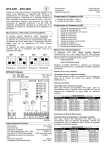
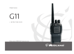
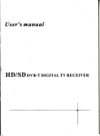
Z l/l » -I ~ ~ nJ ::::::::.. :::::::- m ~JJ § 0 : JJ o:J 0 . m < $: C/) !... CD C/) c I» l/l l/l m JJ m r CONTENTS 1. Introduction 1.1 Function and Features 1.2 Application ----------- I .3 Accessories --- -- -- -- ----- -- ------ -- ------- ----- ------- --- -2 1.4 Technical specifications ---------------------------------2 2. Hardware and Installation -----------------------------------3 2.1 Transmitter (TXV2400) Buttons and Rear Panel Instructions --------------------3 2.2 Receiver (TRV2400) Buttons and Rear Panel Instmctions --------------------3 2.3 Placement of Transmitter (TXV2400)-------------------4 2.4 Placement of Receiver (TRV2400) ----------------- -----6 2.5 Placement of Antenna ---------------- ------------ -------6 3. Operation Instruction ----------- 3.1 Signal Channel Selection ------------------------------- -7 3.2 Power Switch --------------------------------------------- 7 3.3 Channel Selection ----------------------------- ----------- 8 3.4 Infrared control feedback -------------------------------9 4. FAQ and Troubleshooting --- ------------------- -----------10 Thanks for use GADMEI GM2400 wireless AN transceiver! In order to use our product more conveniently, please read this manual carefull y. ,II ~ G~DMe. 1 1. Introduction GM2400 wireless AIV transceiver consists of Transmitter (TXV2400) and receiver (TRV2400). It adopts advanced 2.4GHz wireless transmission technology, with strong anti-interference and mobility. When used in conjunction with set-top box, DVD, VCD and etc, it can be installed easily, subject to no space limitation and without any use of wire connection. It can make audio and video transmitting easily available in every room at home, letting you enjoy HlFI audio and video freely at every corner at home. l.1 Function and Features • 2.4GHz ISM channel • Four set of transmitting channels can be selected for use, improving feasibility and reliability • Transmitter and receiver can be used in match within the same channel,and one-to-multiple, and multiple-to-multiple are available • Compatible with AV output equipments such as video recorder, video camera, digital camera and digital set-top box .433MHz infrared remote returning transmission, fully compatible with remote control of DVDIVCDI digital et-top box • Strong infrared emission, no need to install infrared emission extension cord • Received image is clear and stable, with bright color, and stereo sound • Support NTSC/PAL system video and stereophonic audio transmis sion • Complete hardware design, no need to install software, plug and play, easy and convenient ~ 2 CiOADMEI ~ 3 CiOAOMEI 2. Hardware and Installation 1.2 Application • A/V to A/V wireless transmis sion, can be used when many televi sions share one DVD/VCD or one digital set-top box and etc. • Video conference system in large conference room, and multimedia teaching in classroom. • Connect to pick-up head fo r monitoring;can be used in security systems. • Building and industry monitoring system, long-distance custody of children and patient. • Places where construction is difficult or cost is high. 2.1 Transmitter (TXV2400) Buttons and Rear Panel Instructions I 1.3 Accessories Transmitter (TXV2400)--------------------------------------------1 pcs Receiver (TRV2400) --------------------------------------------1 pes Power ada p ter ---------------------------------------------------2pes AV cable------------ - ----------------------------------2pcs MMI AV cable------------------------------------------------------1 pes U ser's Manual---------------------------------------------------1 pes AV2 input MMJ ex tensionAV I input Infrared transducer source switch 433MHz antenna 2.2 Receiver (TRV2400) Buttons and Rear Panel Instructions 1.4 Technical specifications Power input: Video Input: Audio input: Video output: Audio output: i DCSV=200mA 1Vp-p (PALINTSC) ::S; I .SVp-p(dual track) I Vp-p (PALINTSC) ::S; I.SVp-p(dual track) AVoutput 433MHz antenna source switch 4 ---'~~~~ ~ C;- 5 CiADMel _ _ _ _ CiADMEI @ Use infrared emitting equipment at the back of transmitter: 2.3 Placement of Transmitter (TXV2400) place transmitter in front of AV equipments, and point the infrared emitting window on the back of the transmitter the infrared receiving window of AV equipments. Make sure there are no barriers between them. For normal transmission,please place the transmitter(TXV2400) in the following two ways: e Use infrared emitting equipment at the front of Transmitter: place the transmitter(TXV 2400) on top of AV equipments and keep a distance of 2-3cm between the edge of transmitter and the edge of AV equipments as the right picture.Point it to the infrared receiving window of AV equipments. I t SC HOp box/DVD pl aye r TXV2400 / rt , = ~ / ) I I Set· lO p box /DVD playe r r '~ TXV2400 te:::!S 2-3cm Tips: • There are words like "infrared remote control" or "IR" on the infrared remote receiving window of set-top box (STB) or DVD, please point transmitter's infrared emitting window to it. • There are infrared emitting windows at the front and rear side of TXV2400, as the picture: Tips: To ensure optimal effects, this positioning method is recommended when condition allows. Rear infrared e milling window h ~:--;tJ1 Se HOp box/DV D player Set-top boxfDVD player r ",=,1 OOOn/ \ TXV2400 -_.... '\. Front infrared emitting w indow I ~ 6 _ _ _ _ _ _ _ _ _ _ _ _ _ _ GADMe. ~ l GADMel 3. Operation Instruction 2.4 Placement of receiver (TRV 2400) Please place receiver (TRV2400) beside the TV set, turn it on and connectAV cables according to relative colors (yellow,white and red). ~c/' TRV2400 TV se l /' oo~ 3.1 Signal channel selection AVIIAV2 can be switched freely by pressing source button (Please check hardware instruction for AVl/AV2 input terminal description), and the signal can be normally transmitted only when transceivers are in the same channel. When you switch AVI /AV2 at receiver (TRV2400), transmitter (TXV2400) will automatically switch signal channel according to your operation. The situation of panel indicator light is as follows; AV1 AV2 CH 1 CH2 CH3 CH4 r Video (yellow) -e 0 ' _ _ _ _ _ _ _ _Audio le ft (whire) Audio ri ght (red) 0 0 0 0 I AVl selection mod e TXV2400 TRV2400 AV1 AV2 CH1 CH2 CH3 CH4 2.5 Placement of antenna (. PR t ' , II ~c Please pay attention to the placement of 433MHz antenna, ensuring there is no barriers around it. The barrier of metal will bring very bad influence to the infrared signal. Please straighten the antenna and place it according to following ways. 0 0 0 I P;.~ G ' , I) AV2 selecljon mode 3.2 Power switch Press ~ to connect or cut off power of 2.4GHz transmitter or receiver, switching its operation mode of transmission or non transmission. The panel indicator light of switch flash as follows; \ ' m 'c:::::J::::::: \ . -- . Tips: The 2.4GHz antenna and 433MHz antenna of receiver and transmitter shall be correctly placed, or else it is easy to inference normal transmission of signal. (~ n . c.p c.r,c AV1 AV2 CH1 CH2 CH3 CH4 \ 0 0 I Tum-on: TXV2400 TRV2400 : ___~!!l!_~_I:i~_~ . ?r!a SHi'!le I.U~~-On:- (c ~ ' ':-:\ If AV 1 AV2 CHl CH2 CH3 CH4 o I 0 000 0 I Turn-off: all the panel indicator li ghts are turned off ;::;~ F-i~ ~ 8 ~ .:iADMEI CiAO/I,U"'. 3.3 Channel Selection 3.4 Infrared Remote Feedback Four transmission channels of 2.4GHz can be switched freely by pressing channel switch button. But only when the transceiver is in the same channel can video signals be transmitted normally. Panel indicator li ght for each channel selection mode goes as below : I - GM2400 wireless AV transceiver doesn't need spec ified remote, but it has infrared remote feedback function . When emitting source came from set-top box (STB), DVD , video camera with remote function , remoter come with these equipments can be used directly on the receiver (TRV2400), while you don't have to operate the remote control of the AV equipments . AV1 AV2 CH 1 CH2 CH3 CH4 o 0 -. ~ 0 0 ,'" 0 Step one: Refe r to connecting installation picture, connect transmitter (TXV 24 00 ), and confirm there are no barriers between transmitter's infrared window and infrared receiving window of program source. I The ftrst cbannel selection mod e ,'T AV1 AV2 CH1 CH2 CH3 CH4 o TXV2400 jT~ t , ' , ,) 9 0 0 , ,I Th.~ sc:c.o n ~ . - 0 0 I channe l selection mo~ TRV2400 AV1 AV2 C H1 CH2 CH3 CH4 o 0 0 0 .,', ~. ~ 0 " Step two: When enjoying programs from receiver (TRV2400), point remoter to remote receiving window of the receiver, then you can control AV equipments, which is easy and convenient for operation. ;-:~ , , >J The third channel selectio n mode AV 1 AV2 C H1 CH2 CH3 CH4 Q 0 0 0 0 ~. ~ l Tips: Please pull 433 Mhz antenna of transmitter and receiver as straight as possible, and keep it far away from AV cables,to ensure no interference to signal transmission. In case of infrared remote malfunction , please check antenna's pl acement on condition that there is no pl acement problem with the transce iver. : .'!:~!:. r~urt h c hann~~. ~~I~_~.l.i0n m?~_~. Tips: Please select Channel one or four, to avoid signal interference by wireless local area network (LAN),when there is LAN(802.11 or WiFi) in your family. t ~ 10 (jAcOME. 4. FAQ and Troubleshooting • Indicator does not light and there is no image l.Make sure there is power supply of the transceiver. 2.Change receiver's transmitting channel (refer to operation instruction/ Channel switch) . 3.Adjust transceiver's placement (refer to hardware and installation instruction) . • Infrared Control Feedback malfunction I . Make sure that the connection and installation of the transmitter is correct.(refer to hardware and installation instruction). 2. Please adjust transceiver' s antenna and placement (refer to placement of antenna) . • image is interfered 1. Change receiver's transmitting channel (refer to Channel selection). 2. Please adjust transceiver's placement (refer to hardware and installation instruction) GADMEI-GM2400 Use r's Manual ·Vl .0