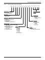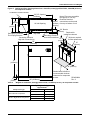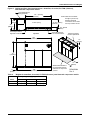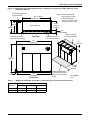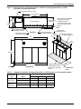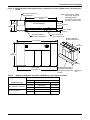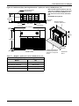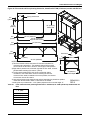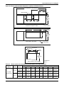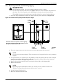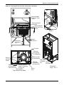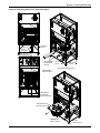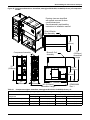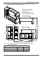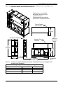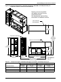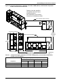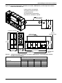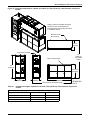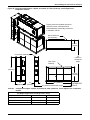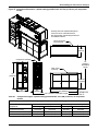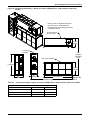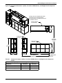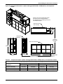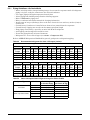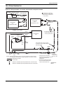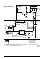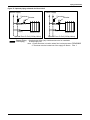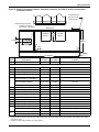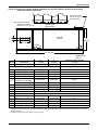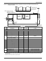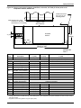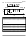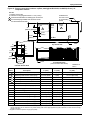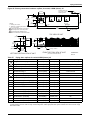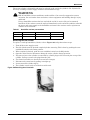
1
Precision Cooling
For Business-Critical Continuity™
Liebert® DS™
User Manual–28-105kW, 8-30 Tons, Upflow and Downflow, 50/60Hz
TABLE OF CONTENTS
IMPORTANT SAFETY INSTRUCTIONS . . . . . . . . . . . . . . . . . . . . . . . . . . . . . . . . . . . . . . . . . . . . . . . .1
SAVE THESE INSTRUCTIONS . . . . . . . . . . . . . . . . . . . . . . . . . . . . . . . . . . . . . . . . . . . . . . . . .1
1.0
LIEBERT DS COMPONENTS AND NOMENCLATURE . . . . . . . . . . . . . . . . . . . . . . . . . . . . . . . .3
2.0
COOLING CONFIGURATIONS . . . . . . . . . . . . . . . . . . . . . . . . . . . . . . . . . . . . . . . . . . . . . . . .6
3.0
PRE-INSTALLATION GUIDELINES . . . . . . . . . . . . . . . . . . . . . . . . . . . . . . . . . . . . . . . . . . . . .7
3.1
Room Preparation. . . . . . . . . . . . . . . . . . . . . . . . . . . . . . . . . . . . . . . . . . . . . . . . . . . . . . . . . . . . 7
3.2
Air Distribution—Downflow Units . . . . . . . . . . . . . . . . . . . . . . . . . . . . . . . . . . . . . . . . . . . . . . 7
3.3
Air Distribution—Upflow Units . . . . . . . . . . . . . . . . . . . . . . . . . . . . . . . . . . . . . . . . . . . . . . . . 8
3.4
Connections and System Setup . . . . . . . . . . . . . . . . . . . . . . . . . . . . . . . . . . . . . . . . . . . . . . . . . 9
3.5
Operating Conditions . . . . . . . . . . . . . . . . . . . . . . . . . . . . . . . . . . . . . . . . . . . . . . . . . . . . . . . . . 9
4.0
LIEBERT DS DIMENSIONS AND WEIGHTS . . . . . . . . . . . . . . . . . . . . . . . . . . . . . . . . . . . . . . 10
5.0
EQUIPMENT INSPECTION AND HANDLING . . . . . . . . . . . . . . . . . . . . . . . . . . . . . . . . . . . . . . 37
5.1
Packaging Material . . . . . . . . . . . . . . . . . . . . . . . . . . . . . . . . . . . . . . . . . . . . . . . . . . . . . . . . . 37
SAFETY INFORMATION . . . . . . . . . . . . . . . . . . . . . . . . . . . . . . . . . . . . . . . . . . . . . . . . . . . . . 37
5.2
Unpacking the Unit . . . . . . . . . . . . . . . . . . . . . . . . . . . . . . . . . . . . . . . . . . . . . . . . . . . . . . . . . 38
5.2.1
5.2.2
5.2.3
5.2.4
Removing the Unit from the Skid With a Forklift . . . . . . . . . . . . . . . . . . . . . . . . . . . . . . . . . .
Moving the Unit to the Installation Location with Piano Jacks . . . . . . . . . . . . . . . . . . . . . . .
Removing Piano Jacks . . . . . . . . . . . . . . . . . . . . . . . . . . . . . . . . . . . . . . . . . . . . . . . . . . . . . . . .
Removing Liebert DS from Skid Using Rigging . . . . . . . . . . . . . . . . . . . . . . . . . . . . . . . . . . . .
39
40
40
41
5.3
Semi-Hermetic Compressor Spring Isolation System . . . . . . . . . . . . . . . . . . . . . . . . . . . . . . 43
5.4
Placing the Unit on a Floor Stand . . . . . . . . . . . . . . . . . . . . . . . . . . . . . . . . . . . . . . . . . . . . . . 43
6.0
EC FANS—LOWERING AND REMOVING . . . . . . . . . . . . . . . . . . . . . . . . . . . . . . . . . . . . . . . 44
6.1
Lowering the EC Fans into the Floor Stand . . . . . . . . . . . . . . . . . . . . . . . . . . . . . . . . . . . . . . 44
6.2
Removing the EC Fans. . . . . . . . . . . . . . . . . . . . . . . . . . . . . . . . . . . . . . . . . . . . . . . . . . . . . . . 47
7.0
DISASSEMBLING THE LIEBERT DS FOR TRANSPORT . . . . . . . . . . . . . . . . . . . . . . . . . . . . . 50
7.1
Required Equipment . . . . . . . . . . . . . . . . . . . . . . . . . . . . . . . . . . . . . . . . . . . . . . . . . . . . . . . . 50
7.2
Disassembly—Downflow Units . . . . . . . . . . . . . . . . . . . . . . . . . . . . . . . . . . . . . . . . . . . . . . . . 51
7.2.1
7.2.2
7.3
Remove the Compressor Assembly . . . . . . . . . . . . . . . . . . . . . . . . . . . . . . . . . . . . . . . . . . . . . . 52
Remove the Filter and Electric Box Assembly . . . . . . . . . . . . . . . . . . . . . . . . . . . . . . . . . . . . . 53
Reassembly—Downflow Units. . . . . . . . . . . . . . . . . . . . . . . . . . . . . . . . . . . . . . . . . . . . . . . . . 53
7.3.1
Reconnecting Piping, Charging and Replacing Panels. . . . . . . . . . . . . . . . . . . . . . . . . . . . . . . 54
7.4
Reassembly Checklist. . . . . . . . . . . . . . . . . . . . . . . . . . . . . . . . . . . . . . . . . . . . . . . . . . . . . . . . 54
7.5
Disassembly—Upflow Units . . . . . . . . . . . . . . . . . . . . . . . . . . . . . . . . . . . . . . . . . . . . . . . . . . 64
7.5.1
7.5.2
Remove Compressor Assembly . . . . . . . . . . . . . . . . . . . . . . . . . . . . . . . . . . . . . . . . . . . . . . . . . 65
Remove Blower and Electric Box Assembly . . . . . . . . . . . . . . . . . . . . . . . . . . . . . . . . . . . . . . . 65
i
7.6
Reassembly—Upflow Unit . . . . . . . . . . . . . . . . . . . . . . . . . . . . . . . . . . . . . . . . . . . . . . . . . . . . 66
7.7
Reassembly Checklist. . . . . . . . . . . . . . . . . . . . . . . . . . . . . . . . . . . . . . . . . . . . . . . . . . . . . . . . 66
8.0
ELECTRICAL CONNECTIONS . . . . . . . . . . . . . . . . . . . . . . . . . . . . . . . . . . . . . . . . . . . . . . . 76
8.1
Variable Speed Drive . . . . . . . . . . . . . . . . . . . . . . . . . . . . . . . . . . . . . . . . . . . . . . . . . . . . . . . . 79
8.1.1
8.1.2
8.1.3
VSD Power Supply—Field-Adjustment May Be Required. . . . . . . . . . . . . . . . . . . . . . . . . . . . 79
Wye-Connected Power Supply . . . . . . . . . . . . . . . . . . . . . . . . . . . . . . . . . . . . . . . . . . . . . . . . . . 79
Delta-Connected Power Supply . . . . . . . . . . . . . . . . . . . . . . . . . . . . . . . . . . . . . . . . . . . . . . . . . 80
9.0
PIPING . . . . . . . . . . . . . . . . . . . . . . . . . . . . . . . . . . . . . . . . . . . . . . . . . . . . . . . . . . . . . . .82
9.1
Fluid Connections. . . . . . . . . . . . . . . . . . . . . . . . . . . . . . . . . . . . . . . . . . . . . . . . . . . . . . . . . . . 82
9.1.1
9.1.2
9.1.3
9.1.4
9.2
82
84
84
84
Refrigeration Piping . . . . . . . . . . . . . . . . . . . . . . . . . . . . . . . . . . . . . . . . . . . . . . . . . . . . . . . . . 85
9.2.1
9.2.2
9.3
Condensate Piping—Field-Installed . . . . . . . . . . . . . . . . . . . . . . . . . . . . . . . . . . . . . . . . . . . . .
Humidifier Supply Water—Optional Infrared . . . . . . . . . . . . . . . . . . . . . . . . . . . . . . . . . . . . .
Humidifier Supply Water—Optional Steam Generating . . . . . . . . . . . . . . . . . . . . . . . . . . . . .
Requirements of Systems Using Water or Glycol . . . . . . . . . . . . . . . . . . . . . . . . . . . . . . . . . . .
Piping Guidelines—Air-Cooled Units . . . . . . . . . . . . . . . . . . . . . . . . . . . . . . . . . . . . . . . . . . . . 86
Scroll and Digital Scroll—Additional Oil Requirements . . . . . . . . . . . . . . . . . . . . . . . . . . . . . 88
Dehydration/Leak Test and Charging Procedures for R-407C and R-22 . . . . . . . . . . . . . . . 89
9.3.1
9.3.2
9.3.3
Air-Cooled Condenser with Variable Fan Speed Head Pressure Control Systems . . . . . . . . 89
Air-Cooled Condenser with Liebert Lee-Temp “Flooded Condenser” Head Pressure
Control System . . . . . . . . . . . . . . . . . . . . . . . . . . . . . . . . . . . . . . . . . . . . . . . . . . . . . . . . . . . . . . 91
Water/Glycol Cooled System . . . . . . . . . . . . . . . . . . . . . . . . . . . . . . . . . . . . . . . . . . . . . . . . . . . 93
10.0
PIPING SCHEMATICS . . . . . . . . . . . . . . . . . . . . . . . . . . . . . . . . . . . . . . . . . . . . . . . . . . . . . 94
11.0
CHECKLIST FOR COMPLETED INSTALLATION . . . . . . . . . . . . . . . . . . . . . . . . . . . . . . . . . . 124
11.1
Moving and Placing Equipment . . . . . . . . . . . . . . . . . . . . . . . . . . . . . . . . . . . . . . . . . . . . . . 124
11.2
Electrical . . . . . . . . . . . . . . . . . . . . . . . . . . . . . . . . . . . . . . . . . . . . . . . . . . . . . . . . . . . . . . . . . 124
11.3
Piping . . . . . . . . . . . . . . . . . . . . . . . . . . . . . . . . . . . . . . . . . . . . . . . . . . . . . . . . . . . . . . . . . . . 124
11.4
Other . . . . . . . . . . . . . . . . . . . . . . . . . . . . . . . . . . . . . . . . . . . . . . . . . . . . . . . . . . . . . . . . . . . . 125
12.0
INITIAL STARTUP CHECKS AND COMMISSIONING PROCEDURE FOR WARRANTY
INSPECTION . . . . . . . . . . . . . . . . . . . . . . . . . . . . . . . . . . . . . . . . . . . . . . . . . . . . . . . . . .126
12.1
Information for Warranty Inspection—Remove Power From Unit Disconnect . . . . . . . . . 127
12.2
Startup Checks With Panels Removed and Main Disconnect Off . . . . . . . . . . . . . . . . . . . . 127
12.2.1 Inspect and Record . . . . . . . . . . . . . . . . . . . . . . . . . . . . . . . . . . . . . . . . . . . . . . . . . . . . . . . . . . 127
12.3
Startup . . . . . . . . . . . . . . . . . . . . . . . . . . . . . . . . . . . . . . . . . . . . . . . . . . . . . . . . . . . . . . . . . . 128
12.4
Commissioning Procedure With Panels On . . . . . . . . . . . . . . . . . . . . . . . . . . . . . . . . . . . . . 129
13.0
MAINTENANCE . . . . . . . . . . . . . . . . . . . . . . . . . . . . . . . . . . . . . . . . . . . . . . . . . . . . . . . . 130
13.1
Filters . . . . . . . . . . . . . . . . . . . . . . . . . . . . . . . . . . . . . . . . . . . . . . . . . . . . . . . . . . . . . . . . . . . 131
13.1.1 Filter Replacement Procedure—Downflow Units. . . . . . . . . . . . . . . . . . . . . . . . . . . . . . . . . . 132
13.1.2 Filter Replacement Procedure—Upflow Units . . . . . . . . . . . . . . . . . . . . . . . . . . . . . . . . . . . . 132
ii
13.2
Blower Drive System—Centrifugal Fans . . . . . . . . . . . . . . . . . . . . . . . . . . . . . . . . . . . . . . . 132
13.2.1
13.2.2
13.2.3
13.2.4
13.3
Upflow Motor Access . . . . . . . . . . . . . . . . . . . . . . . . . . . . . . . . . . . . . . . . . . . . . . . . . . . . . . . .
Belt Removal. . . . . . . . . . . . . . . . . . . . . . . . . . . . . . . . . . . . . . . . . . . . . . . . . . . . . . . . . . . . . . .
Belt Installation and Tensioning . . . . . . . . . . . . . . . . . . . . . . . . . . . . . . . . . . . . . . . . . . . . . . .
Electronic Variable Speed Drive - Inverter. . . . . . . . . . . . . . . . . . . . . . . . . . . . . . . . . . . . . . .
133
133
134
135
Blower Drive System—EC Fans . . . . . . . . . . . . . . . . . . . . . . . . . . . . . . . . . . . . . . . . . . . . . . 135
13.3.1 Fan Impellers and Bearings. . . . . . . . . . . . . . . . . . . . . . . . . . . . . . . . . . . . . . . . . . . . . . . . . . . 135
13.3.2 Protective Features . . . . . . . . . . . . . . . . . . . . . . . . . . . . . . . . . . . . . . . . . . . . . . . . . . . . . . . . . 135
13.4
Humidifier—Infrared . . . . . . . . . . . . . . . . . . . . . . . . . . . . . . . . . . . . . . . . . . . . . . . . . . . . . . . 136
13.4.1 Cleaning Humidifier Pan and Float Switch . . . . . . . . . . . . . . . . . . . . . . . . . . . . . . . . . . . . . . 136
13.4.2 Changing Humidifier Lamps . . . . . . . . . . . . . . . . . . . . . . . . . . . . . . . . . . . . . . . . . . . . . . . . . . 137
13.5
Humidifier—Steam Generating . . . . . . . . . . . . . . . . . . . . . . . . . . . . . . . . . . . . . . . . . . . . . . 138
13.5.1 Replacing the Steam Generating Humidifier Canister . . . . . . . . . . . . . . . . . . . . . . . . . . . . . 138
13.6
Condensate Drain and Condensate Pump Systems . . . . . . . . . . . . . . . . . . . . . . . . . . . . . . . 143
13.6.1 Condensate Drain . . . . . . . . . . . . . . . . . . . . . . . . . . . . . . . . . . . . . . . . . . . . . . . . . . . . . . . . . . . 143
13.6.2 Condensate Pump . . . . . . . . . . . . . . . . . . . . . . . . . . . . . . . . . . . . . . . . . . . . . . . . . . . . . . . . . . 143
13.7
Air-Cooled Condenser and Drycoolers. . . . . . . . . . . . . . . . . . . . . . . . . . . . . . . . . . . . . . . . . . 144
13.8
Reheat—Electric Reheat (Three-Stage and SCR) . . . . . . . . . . . . . . . . . . . . . . . . . . . . . . . . 144
13.9
Thermostatic Expansion Valve . . . . . . . . . . . . . . . . . . . . . . . . . . . . . . . . . . . . . . . . . . . . . . . 144
13.9.1 Determine Suction Superheat . . . . . . . . . . . . . . . . . . . . . . . . . . . . . . . . . . . . . . . . . . . . . . . . . 144
13.9.2 Adjust Superheat Setting with the TEV . . . . . . . . . . . . . . . . . . . . . . . . . . . . . . . . . . . . . . . . . 144
13.10 Compressor . . . . . . . . . . . . . . . . . . . . . . . . . . . . . . . . . . . . . . . . . . . . . . . . . . . . . . . . . . . . . . . 145
13.10.1 Compressor Oil . . . . . . . . . . . . . . . . . . . . . . . . . . . . . . . . . . . . . . . . . . . . . . . . . . . . . . . . . . . . . 145
13.10.2 Semi-Hermetic Compressors . . . . . . . . . . . . . . . . . . . . . . . . . . . . . . . . . . . . . . . . . . . . . . . . . . 145
13.10.3 Scroll and Digital Scroll Compressors . . . . . . . . . . . . . . . . . . . . . . . . . . . . . . . . . . . . . . . . . . . 145
13.11 Compressor Replacement. . . . . . . . . . . . . . . . . . . . . . . . . . . . . . . . . . . . . . . . . . . . . . . . . . . . 145
13.11.1 Compressor Motor Burnout . . . . . . . . . . . . . . . . . . . . . . . . . . . . . . . . . . . . . . . . . . . . . . . . . . . 145
13.11.2 Digital Compressor Unloading Solenoid(s) . . . . . . . . . . . . . . . . . . . . . . . . . . . . . . . . . . . . . . . 146
13.11.3 Compressor Replacement Procedure . . . . . . . . . . . . . . . . . . . . . . . . . . . . . . . . . . . . . . . . . . . . 146
13.12 Facility Fluid and Piping Maintenance. . . . . . . . . . . . . . . . . . . . . . . . . . . . . . . . . . . . . . . . . 146
13.13 Paradenser—Water-Cooled Condenser . . . . . . . . . . . . . . . . . . . . . . . . . . . . . . . . . . . . . . . . . 146
13.13.1 Cleaning Instructions. . . . . . . . . . . . . . . . . . . . . . . . . . . . . . . . . . . . . . . . . . . . . . . . . . . . . . . . 147
13.14 Water/Glycol Control Valves . . . . . . . . . . . . . . . . . . . . . . . . . . . . . . . . . . . . . . . . . . . . . . . . . 147
13.14.1 Regulating Valves – Semi Hermetic and Standard Scroll Compressors . . . . . . . . . . . . . . . . 147
13.14.2 Motor Ball Valve—Digital Scroll Compressors. . . . . . . . . . . . . . . . . . . . . . . . . . . . . . . . . . . . 148
13.14.3 Drycooler Settings . . . . . . . . . . . . . . . . . . . . . . . . . . . . . . . . . . . . . . . . . . . . . . . . . . . . . . . . . . 149
14.0
HVAC MAINTENANCE CHECKLIST . . . . . . . . . . . . . . . . . . . . . . . . . . . . . . . . . . . . . . . . . . 150
COMPLIANCE WITH EUROPEAN UNION DIRECTIVES . . . . . . . . . . . . . . . . . . . . . . INSIDE BACK COVER
iii
FIGURES
Figure 1
Figure 2
Figure 3
Figure 4
Figure 5
Figure 6
Figure 7
Figure 8
Figure 9
Figure 10
Figure 11
Figure 12
Figure 13
Figure 14
Figure 15
Figure 16
Figure 17
Figure 18
Figure 19
Figure 20
Figure 21
Figure 22
Figure 23
Figure 24
Figure 25
Figure 26
Figure 27
Figure 28
Figure 29
Figure 30
Figure 31
Figure 32
Figure 33
Figure 34
Figure 35
Figure 36
Downflow model component locations . . . . . . . . . . . . . . . . . . . . . . . . . . . . . . . . . . . . . . . . . . . . . . . . 3
Upflow model component locations . . . . . . . . . . . . . . . . . . . . . . . . . . . . . . . . . . . . . . . . . . . . . . . . . . 4
Liebert DS model number nomenclature. . . . . . . . . . . . . . . . . . . . . . . . . . . . . . . . . . . . . . . . . . . . . . 5
Downflow unit ducting and plenum ducting . . . . . . . . . . . . . . . . . . . . . . . . . . . . . . . . . . . . . . . . . . . 7
Upflow ducting configurations . . . . . . . . . . . . . . . . . . . . . . . . . . . . . . . . . . . . . . . . . . . . . . . . . . . . . . 8
Cabinet and floor planning dimensions—downflow, air-cooled, 28-42kW (8-12 ton),
semi-hermetic compressor models . . . . . . . . . . . . . . . . . . . . . . . . . . . . . . . . . . . . . . . . . . . . . . . . . . 11
Cabinet and floor planning dimensions—downflow, air-cooled, 28-42kW (8-12 ton),
scroll compressor models . . . . . . . . . . . . . . . . . . . . . . . . . . . . . . . . . . . . . . . . . . . . . . . . . . . . . . . . . 12
Cabinet and floor planning dimensions—downflow, water/glycol/GLYCOOL, 28-42kW
(8-12 ton), all compressor models . . . . . . . . . . . . . . . . . . . . . . . . . . . . . . . . . . . . . . . . . . . . . . . . . . . 13
Cabinet and floor planning dimensions—downflow, air-cooled, 53-77kW (15-22 ton),
semi-hermetic compressor models . . . . . . . . . . . . . . . . . . . . . . . . . . . . . . . . . . . . . . . . . . . . . . . . . . 14
Cabinet and floor planning dimensions—downflow, air-cooled, 53-77kW (15-22 ton),
scroll compressor models . . . . . . . . . . . . . . . . . . . . . . . . . . . . . . . . . . . . . . . . . . . . . . . . . . . . . . . . . 15
Cabinet and floor planning dimensions—downflow, water/glycol/GLYCOOL, 53-77kW
(15-22 ton), all compressor models . . . . . . . . . . . . . . . . . . . . . . . . . . . . . . . . . . . . . . . . . . . . . . . . . . 16
Cabinet and floor planning dimensions—downflow, air-cooled, 105kW (30 ton), all
compressor models . . . . . . . . . . . . . . . . . . . . . . . . . . . . . . . . . . . . . . . . . . . . . . . . . . . . . . . . . . . . . . 17
Cabinet and floor planning dimensions—downflow, water/glycol/GLYCOOL, 105kW
(30 ton), all compressor models . . . . . . . . . . . . . . . . . . . . . . . . . . . . . . . . . . . . . . . . . . . . . . . . . . . . 18
Cabinet and floor planning dimensions—upflow, air-cooled 28-42kW (8-12 ton),
semi-hermetic compressor models . . . . . . . . . . . . . . . . . . . . . . . . . . . . . . . . . . . . . . . . . . . . . . . . . . 19
Cabinet and floor planning dimensions—upflow, air-cooled 28-42kW (8-12 ton),
scroll or digital scroll compressor models . . . . . . . . . . . . . . . . . . . . . . . . . . . . . . . . . . . . . . . . . . . . 20
Cabinet and floor planning dimensions—upflow, water/glycol/GLYCOOL, 28-42kW
(8-12 ton), all compressor models . . . . . . . . . . . . . . . . . . . . . . . . . . . . . . . . . . . . . . . . . . . . . . . . . . . 21
Cabinet and floor planning dimensions—upflow, air-cooled, 53-77kW (15-22 ton),
semi-hermetic compressor models . . . . . . . . . . . . . . . . . . . . . . . . . . . . . . . . . . . . . . . . . . . . . . . . . . 22
Cabinet and floor planning dimensions—upflow, air-cooled, 53-77kW (15-22 ton),
scroll or digital scroll compressor models . . . . . . . . . . . . . . . . . . . . . . . . . . . . . . . . . . . . . . . . . . . . 23
Cabinet and floor planning dimensions—upflow, water/glycol/GLYCOOL, 53-77kW
(15-22 ton), all compressor models . . . . . . . . . . . . . . . . . . . . . . . . . . . . . . . . . . . . . . . . . . . . . . . . . . 24
Cabinet and floor planning dimensions—upflow, air-cooled, 105kW (30 ton), all . . . . . . . . . . . . 25
Cabinet and floor planning dimensions—upflow water/glycol/GLYCOOL 105kW (30 ton),
all compressors . . . . . . . . . . . . . . . . . . . . . . . . . . . . . . . . . . . . . . . . . . . . . . . . . . . . . . . . . . . . . . . . . 26
Floor stand dimensions—downflow, 28-42kW (8-12 ton) models. . . . . . . . . . . . . . . . . . . . . . . . . . 27
Floor stand dimensions—downflow, 53-77kW (15-22 ton) models. . . . . . . . . . . . . . . . . . . . . . . . . 28
Floor stand and floor planning dimension, downflow 53-77kW (15-22 tons) models with
EC fans . . . . . . . . . . . . . . . . . . . . . . . . . . . . . . . . . . . . . . . . . . . . . . . . . . . . . . . . . . . . . . . . . . . . . . . 29
Floor stand dimensions—downflow, 105kW (30 ton) models . . . . . . . . . . . . . . . . . . . . . . . . . . . . . 30
Floor stand and floor planning dimension, downflow 105kW (30 tons) models with EC fans . . . 31
Blower outlet and deck dimensions—upflow, 28-42kW (8-12 ton). . . . . . . . . . . . . . . . . . . . . . . . . 32
Blower outlet and deck dimensions—upflow, 53-77kW (15-22 ton). . . . . . . . . . . . . . . . . . . . . . . . 33
Blower outlet and deck dimensions—upflow 105kW (30ton) . . . . . . . . . . . . . . . . . . . . . . . . . . . . . 34
Rear return filter box dimensions . . . . . . . . . . . . . . . . . . . . . . . . . . . . . . . . . . . . . . . . . . . . . . . . . . 35
Upflow unit plenum dimensions . . . . . . . . . . . . . . . . . . . . . . . . . . . . . . . . . . . . . . . . . . . . . . . . . . . 36
Equipment recommended for handling Liebert DS . . . . . . . . . . . . . . . . . . . . . . . . . . . . . . . . . . . . 37
Removing packaging . . . . . . . . . . . . . . . . . . . . . . . . . . . . . . . . . . . . . . . . . . . . . . . . . . . . . . . . . . . . . 38
Remove the unit from the skid . . . . . . . . . . . . . . . . . . . . . . . . . . . . . . . . . . . . . . . . . . . . . . . . . . . . . 39
Moving the unit to its installation location . . . . . . . . . . . . . . . . . . . . . . . . . . . . . . . . . . . . . . . . . . . 40
Locate center of gravity marker and place slings . . . . . . . . . . . . . . . . . . . . . . . . . . . . . . . . . . . . . . 41
iv
Figure 37
Figure 38
Figure 39
Figure 40
Figure 41
Figure 42
Figure 43
Figure 44
Figure 45
Figure 46
Figure 47
Figure 48
Figure 49
Figure 50
Figure 51
Figure 52
Figure 53
Figure 54
Figure 55
Figure 56
Figure 57
Figure 58
Figure 59
Figure 60
Figure 61
Figure 62
Figure 63
Figure 64
Figure 65
Figure 66
Figure 67
Figure 68
Figure 69
Figure 70
Figure 71
Using rigging to lift Liebert DS off skid . . . . . . . . . . . . . . . . . . . . . . . . . . . . . . . . . . . . . . . . . . . . .
Setting the unit on a floor stand . . . . . . . . . . . . . . . . . . . . . . . . . . . . . . . . . . . . . . . . . . . . . . . . . . .
Lowering EC fans into floor stand, Steps 1 through 6 . . . . . . . . . . . . . . . . . . . . . . . . . . . . . . . . . .
Lowering EC fans into floor stand, Steps 7 through 9 . . . . . . . . . . . . . . . . . . . . . . . . . . . . . . . . . .
Removing the EC fans, Steps 1 through 5 . . . . . . . . . . . . . . . . . . . . . . . . . . . . . . . . . . . . . . . . . . . .
Removing the EC fans, Steps 6 through 9 . . . . . . . . . . . . . . . . . . . . . . . . . . . . . . . . . . . . . . . . . . .
Component dimensions—downflow, air-cooled, 28-42kW (8-12 ton), semi-hermetic
compressor models . . . . . . . . . . . . . . . . . . . . . . . . . . . . . . . . . . . . . . . . . . . . . . . . . . . . . . . . . . . . . .
Component dimensions—downflow, air-cooled, 28-42kW (8-12 ton), scroll/digital scroll
compressor models . . . . . . . . . . . . . . . . . . . . . . . . . . . . . . . . . . . . . . . . . . . . . . . . . . . . . . . . . . . . . .
Component dimensions—downflow, water/glycol/GLYCOOL, 28-42kW (8-12 ton), all
compressor models . . . . . . . . . . . . . . . . . . . . . . . . . . . . . . . . . . . . . . . . . . . . . . . . . . . . . . . . . . . . . .
Component dimensions—downflow, air-cooled, 53-77kW (15-22 ton), semi-hermetic
compressor models; forward-curved and EC fan . . . . . . . . . . . . . . . . . . . . . . . . . . . . . . . . . . . . . . .
Component dimensions—downflow air-cooled, 53-77kW (15-22 ton), scroll/digital scroll
compressor models; forward-curved and EC fan . . . . . . . . . . . . . . . . . . . . . . . . . . . . . . . . . . . . . . .
Component dimensions—downflow water/glycol, GLYCOOL, 53-77kW (15-22 ton), all
compressor models; forward-curved and EC fan . . . . . . . . . . . . . . . . . . . . . . . . . . . . . . . . . . . . . . .
Component dimensions—downflow, air-cooled, 105kW (30 ton), semi-hermetic compressor
models; forward-curved and EC fan. . . . . . . . . . . . . . . . . . . . . . . . . . . . . . . . . . . . . . . . . . . . . . . . .
Component dimensions—downflow, air-cooled, 105kW (30 ton), scroll compressor models;
forward-curved and EC fan . . . . . . . . . . . . . . . . . . . . . . . . . . . . . . . . . . . . . . . . . . . . . . . . . . . . . . .
Component dimensions—downflow, water/glycol/GLYCOOL, 105kW (30 ton),
forward-curved and EC fan, all compressor models; forward-curved and EC fan . . . . . . . . . . . .
Component dimensions—upflow, air-cooled, 28-42kW (8-12 ton), semi-hermetic compressor
models . . . . . . . . . . . . . . . . . . . . . . . . . . . . . . . . . . . . . . . . . . . . . . . . . . . . . . . . . . . . . . . . . . . . . . . .
Component dimensions—upflow, air-cooled, 28-42kW (8-12 ton), scroll/digital scroll
compressor models . . . . . . . . . . . . . . . . . . . . . . . . . . . . . . . . . . . . . . . . . . . . . . . . . . . . . . . . . . . . . .
Component dimensions—upflow, water/glycol/GLYCOOL, 28-42kW (8-12 ton), all
compressor models . . . . . . . . . . . . . . . . . . . . . . . . . . . . . . . . . . . . . . . . . . . . . . . . . . . . . . . . . . . . . .
Component dimensions—upflow, air-cooled, 53-77kw (15-22 ton), semi-hermetic
compressor models . . . . . . . . . . . . . . . . . . . . . . . . . . . . . . . . . . . . . . . . . . . . . . . . . . . . . . . . . . . . . .
Component dimensions—upflow, air-cooled, 53-77kw (15-22 ton), scroll/digital scroll
compressor models . . . . . . . . . . . . . . . . . . . . . . . . . . . . . . . . . . . . . . . . . . . . . . . . . . . . . . . . . . . . . .
Component dimensions—upflow water/glycol/GLYCOOL 53-77kw (15-22 ton), all
compressor models . . . . . . . . . . . . . . . . . . . . . . . . . . . . . . . . . . . . . . . . . . . . . . . . . . . . . . . . . . . . . .
Component dimensions—upflow, air-cooled, 105kW (30 ton), semi-hermetic compressor
models . . . . . . . . . . . . . . . . . . . . . . . . . . . . . . . . . . . . . . . . . . . . . . . . . . . . . . . . . . . . . . . . . . . . . . . .
Component dimensions—upflow, air-cooled, 105kW (30 ton), scroll/digital scroll
compressor models . . . . . . . . . . . . . . . . . . . . . . . . . . . . . . . . . . . . . . . . . . . . . . . . . . . . . . . . . . . . . .
Component dimensions—upflow, water/glycol/GLYCOOL, 105kW (30 ton), all
compressor models . . . . . . . . . . . . . . . . . . . . . . . . . . . . . . . . . . . . . . . . . . . . . . . . . . . . . . . . . . . . . .
Electrical field connections for upflow and downflow models . . . . . . . . . . . . . . . . . . . . . . . . . . . .
Wye-connected power diagram. . . . . . . . . . . . . . . . . . . . . . . . . . . . . . . . . . . . . . . . . . . . . . . . . . . . .
Delta-connected power diagram . . . . . . . . . . . . . . . . . . . . . . . . . . . . . . . . . . . . . . . . . . . . . . . . . . . .
Disconnecting EMC filter for operation with Delta-connected power size C & D inverters. . . . .
Figure bb Disconnecting EMC filter for operation with Delta-connected power Type 2
inverters. . . . . . . . . . . . . . . . . . . . . . . . . . . . . . . . . . . . . . . . . . . . . . . . . . . . . . . . . . . . . . . . . . . . . . .
Gravity drain for downflow and upflow units . . . . . . . . . . . . . . . . . . . . . . . . . . . . . . . . . . . . . . . . .
Piping schematic—air-cooled, semi-hermetic compressor models . . . . . . . . . . . . . . . . . . . . . . . . .
Piping schematic—air-cooled, scroll compressor models . . . . . . . . . . . . . . . . . . . . . . . . . . . . . . . .
Piping schematic—water/glycol, semi-hermetic compressor models . . . . . . . . . . . . . . . . . . . . . . .
Piping schematic—water/glycol with scroll compressor models. . . . . . . . . . . . . . . . . . . . . . . . . . .
Piping schematic—GLYCOOL semi-hermetic compressor models . . . . . . . . . . . . . . . . . . . . . . . .
v
42
43
45
46
48
49
55
56
57
58
59
60
61
62
63
67
68
69
70
71
72
73
74
75
77
79
80
81
81
83
94
95
96
97
98
Figure 72
Figure 73
Figure 74
Figure 75
Figure 76
Figure 77
Figure 78
Figure 79
Figure 80
Figure 81
Figure 82
Figure 83
Figure 84
Figure 85
Figure 86
Figure 87
Figure 88
Figure 89
Figure 90
Figure 91
Figure 92
Figure 93
Figure 94
Figure 95
Figure 96
Figure 97
Figure 98
Figure 99
Figure 100
Figure 101
Figure 102
Figure 103
Figure 104
Figure 105
Figure 106
Piping schematic—GLYCOOL with scroll compressor models . . . . . . . . . . . . . . . . . . . . . . . . . . . 99
Piping schematic—water/glycol with digital scroll compressor models. . . . . . . . . . . . . . . . . . . . 100
GLYCOOL with digital scroll compressor models. . . . . . . . . . . . . . . . . . . . . . . . . . . . . . . . . . . . . 101
Optional piping schematic for Econ-O-Coil . . . . . . . . . . . . . . . . . . . . . . . . . . . . . . . . . . . . . . . . . . 102
Primary connection locations—downflow, air-cooled, 28-42kW (8-12 ton), semi-hermetic
compressor models . . . . . . . . . . . . . . . . . . . . . . . . . . . . . . . . . . . . . . . . . . . . . . . . . . . . . . . . . . . . . 103
Primary connection locations—downflow, air-Cooled, 28-42kW (8-12 ton) with scroll
compressor models . . . . . . . . . . . . . . . . . . . . . . . . . . . . . . . . . . . . . . . . . . . . . . . . . . . . . . . . . . . . . 104
Primary connection locations—downflow water/glycol/GLYCOOL 28-42kW (8-12 ton),
all compressor models . . . . . . . . . . . . . . . . . . . . . . . . . . . . . . . . . . . . . . . . . . . . . . . . . . . . . . . . . . . 105
Primary connection locations—downflow, air-Cooled, 53-77kW (15-22 ton), semi-hermetic
compressor models . . . . . . . . . . . . . . . . . . . . . . . . . . . . . . . . . . . . . . . . . . . . . . . . . . . . . . . . . . . . . 106
Primary connection locations downflow air cooled 53-77kW (15-22 tons) semi-hermetic
compressor models, with EC fan . . . . . . . . . . . . . . . . . . . . . . . . . . . . . . . . . . . . . . . . . . . . . . . . . . 107
Primary connection locations—downflow, air-Cooled, 53-77kW (15-22 ton) with scroll
compressor models . . . . . . . . . . . . . . . . . . . . . . . . . . . . . . . . . . . . . . . . . . . . . . . . . . . . . . . . . . . . . 108
Primary connection locations—downflow, air-Cooled, 53-77kW (15-22 ton) with scroll
compressor models, with EC fan . . . . . . . . . . . . . . . . . . . . . . . . . . . . . . . . . . . . . . . . . . . . . . . . . . 109
Primary connection locations—downflow, water/glycol/GLYCOOL, 53-77kW (15-22 ton),
all compressor models . . . . . . . . . . . . . . . . . . . . . . . . . . . . . . . . . . . . . . . . . . . . . . . . . . . . . . . . . . . 110
Primary connection locations—downflow, water/glycol/GLYCOOL, 53-77kW (15-22 ton),
all compressor models, with EC fan. . . . . . . . . . . . . . . . . . . . . . . . . . . . . . . . . . . . . . . . . . . . . . . . 111
Primary connection locations—downflow, air-cooled, 105kW (30 ton), all compressor
models . . . . . . . . . . . . . . . . . . . . . . . . . . . . . . . . . . . . . . . . . . . . . . . . . . . . . . . . . . . . . . . . . . . . . . . 112
Primary connection locations—downflow, air-cooled, 105kW (30 ton), all compressor
models, with EC fan . . . . . . . . . . . . . . . . . . . . . . . . . . . . . . . . . . . . . . . . . . . . . . . . . . . . . . . . . . . . 113
Primary connection locations—downflow, water/glycol/GLYCOOL, 105kW (30 ton), all
compressor models . . . . . . . . . . . . . . . . . . . . . . . . . . . . . . . . . . . . . . . . . . . . . . . . . . . . . . . . . . . . . 114
Primary connection locations downflow water/glycol/GLYCOOL 105kW (30 tons) all
compressor models, with EC fan . . . . . . . . . . . . . . . . . . . . . . . . . . . . . . . . . . . . . . . . . . . . . . . . . . 115
Primary connection locations—upflow, air-cooled, 28-42kw (8-12 ton), semi-hermetic
compressor models . . . . . . . . . . . . . . . . . . . . . . . . . . . . . . . . . . . . . . . . . . . . . . . . . . . . . . . . . . . . . 116
Primary connection locations—upflow, air-Cooled, 28-42kW (8-12 ton), semi-hermetic
compressor models . . . . . . . . . . . . . . . . . . . . . . . . . . . . . . . . . . . . . . . . . . . . . . . . . . . . . . . . . . . . . 117
Primary connection locations—upflow, water/glycol/GLYCOOL, 28-42kW (8-12 ton),
all compressor models . . . . . . . . . . . . . . . . . . . . . . . . . . . . . . . . . . . . . . . . . . . . . . . . . . . . . . . . . . . 118
Primary connection locations—upflow, air-cooled, 53-77kW (15-22 ton), semi-hermetic
compressor models . . . . . . . . . . . . . . . . . . . . . . . . . . . . . . . . . . . . . . . . . . . . . . . . . . . . . . . . . . . . . 119
Primary connection locations—upflow, air-cooled, 53-77kW (15-22 ton), scroll compressor
models . . . . . . . . . . . . . . . . . . . . . . . . . . . . . . . . . . . . . . . . . . . . . . . . . . . . . . . . . . . . . . . . . . . . . . . 120
Primary connection locations—upflow, water/glycol/GLYCOOL, 53-77kW (15-22 ton),
all compressor models . . . . . . . . . . . . . . . . . . . . . . . . . . . . . . . . . . . . . . . . . . . . . . . . . . . . . . . . . . . 121
Primary connection locations—upflow, air-cooled, 105kW (30 ton), all. . . . . . . . . . . . . . . . . . . . 122
Primary connection locations—upflow, water/glycol/GLYCOOL, 105kW (30 ton), all . . . . . . . . 123
Proper filter pleat direction . . . . . . . . . . . . . . . . . . . . . . . . . . . . . . . . . . . . . . . . . . . . . . . . . . . . . . 132
Upflow motor access . . . . . . . . . . . . . . . . . . . . . . . . . . . . . . . . . . . . . . . . . . . . . . . . . . . . . . . . . . . . 133
Auto-belt tensioning motor base . . . . . . . . . . . . . . . . . . . . . . . . . . . . . . . . . . . . . . . . . . . . . . . . . . 134
Correct orientation of float switch . . . . . . . . . . . . . . . . . . . . . . . . . . . . . . . . . . . . . . . . . . . . . . . . . 137
Infrared humidifier lamps . . . . . . . . . . . . . . . . . . . . . . . . . . . . . . . . . . . . . . . . . . . . . . . . . . . . . . . 137
Steam generating humidifier canister . . . . . . . . . . . . . . . . . . . . . . . . . . . . . . . . . . . . . . . . . . . . . . 138
Removing the old canister . . . . . . . . . . . . . . . . . . . . . . . . . . . . . . . . . . . . . . . . . . . . . . . . . . . . . . . 139
Drain valve assembly . . . . . . . . . . . . . . . . . . . . . . . . . . . . . . . . . . . . . . . . . . . . . . . . . . . . . . . . . . . 140
Canister plugs . . . . . . . . . . . . . . . . . . . . . . . . . . . . . . . . . . . . . . . . . . . . . . . . . . . . . . . . . . . . . . . . . 141
Circuit board diagram. . . . . . . . . . . . . . . . . . . . . . . . . . . . . . . . . . . . . . . . . . . . . . . . . . . . . . . . . . . 143
vi
TABLES
Table 1
Table 2
Table 3
Table 4
Table 5
Table 6
Table 7
Table 8
Table 9
Table 10
Table 11
Table 12
Table 13
Table 14
Table 15
Table 16
Table 17
Table 18
Table 19
Table 20
Table 21
Table 22
Table 23
Table 24
Table 25
Table 26
Table 27
Table 28
Table 29
Table 30
Table 31
Table 32
Table 33
Table 34
Table 35
Table 36
Table 37
Table 38
Table 39
Shipping dimensions—domestic and export, inches (mm) . . . . . . . . . . . . . . . . . . . . . . . . . . . . . . .
Shipping weights—approximate, kg . . . . . . . . . . . . . . . . . . . . . . . . . . . . . . . . . . . . . . . . . . . . . . . .
Weights for downflow, air-cooled, 28-42kW (8-12 ton), semi-hermetic compressor models . . . . .
Weights for downflow, air-cooled, 28-42kW (8-12 ton), scroll compressor models . . . . . . . . . . . .
Weights for downflow, water/glycol/GLYCOOL, 28-42kW (8-12 ton), all compressor models . . .
Weights for downflow, air-cooled, 53-77kW (15-22 ton), semi-hermetic compressor models . . . .
Weights for downflow, air-cooled, 53-77kW (15-22 ton), scroll compressor models . . . . . . . . . . .
Weights for downflow, water/glycol/GLYCOOL, 53-77kW (15-22 ton), all compressor
models . . . . . . . . . . . . . . . . . . . . . . . . . . . . . . . . . . . . . . . . . . . . . . . . . . . . . . . . . . . . . . . . . . . . . . . .
Weights for downflow, air-Cooled, 105kW (30 ton), all compressor models . . . . . . . . . . . . . . . . .
Weights for downflow, water/glycol/GLYCOOL, 105kW (30 ton), all compressor models . . . . . .
Weight for upflow, air-cooled, 28-42kW (8-12 ton), semi-hermetic compressor models . . . . . . . .
Weight for upflow, air-cooled, 28-42kW (8-12 ton), scroll or digital scroll compressor
models . . . . . . . . . . . . . . . . . . . . . . . . . . . . . . . . . . . . . . . . . . . . . . . . . . . . . . . . . . . . . . . . . . . . . . . .
Weights for upflow, water/glycol/GLYCOOL, 28-42kW (8-12 ton), all compressor models . . . . .
Weights for upflow, air-cooled, 53-77kW (15-22 ton), semi-hermetic compressor models . . . . . .
Weight for upflow, air-cooled, 53-77kW (15-22 ton), scroll or digital scroll compressor
models . . . . . . . . . . . . . . . . . . . . . . . . . . . . . . . . . . . . . . . . . . . . . . . . . . . . . . . . . . . . . . . . . . . . . . . .
Weights for upflow, water/glycol/GLYCOOL, 53-77kW (15-22 ton), all compressor models . . . .
Weights—upflow, air-cooled, 105kW (30 ton), all . . . . . . . . . . . . . . . . . . . . . . . . . . . . . . . . . . . . . .
Weights—upflow water/glycol/GLYCOOL 105kW (30 ton), all compressors. . . . . . . . . . . . . . . . .
Floor stand and floor planning dimensions—downflow, 28-42kW (8-12 ton) models . . . . . . . . . .
Floor stand and floor planning dimensions—downflow, 53-77kW (15-22 ton) models . . . . . . . . .
Floor stand and floor planning dimensions—downflow, 53-77kW (15-22 ton) models
with EC fans . . . . . . . . . . . . . . . . . . . . . . . . . . . . . . . . . . . . . . . . . . . . . . . . . . . . . . . . . . . . . . . . . . .
Floor stand and floor planning dimensions—downflow, 105kW (30 ton) models . . . . . . . . . . . . .
Floor stand and floor planning dimensions—downflow, 105kW (30 ton) models with
EC fans . . . . . . . . . . . . . . . . . . . . . . . . . . . . . . . . . . . . . . . . . . . . . . . . . . . . . . . . . . . . . . . . . . . . . . .
Blower outlet and deck dimensional data for upflow, 28-42kW (8-12 ton) . . . . . . . . . . . . . . . . . .
Blower outlet and deck dimensional data upflow, 53-77kW (15-22 tons) . . . . . . . . . . . . . . . . . . .
Blower outlet and deck dimensions—upflow 105kW (30ton) . . . . . . . . . . . . . . . . . . . . . . . . . . . . .
Rear return filter box dimensions . . . . . . . . . . . . . . . . . . . . . . . . . . . . . . . . . . . . . . . . . . . . . . . . . .
Upflow unit plenum dimensions . . . . . . . . . . . . . . . . . . . . . . . . . . . . . . . . . . . . . . . . . . . . . . . . . . .
Component weights—downflow, air-cooled, 28-42kW (8-12 ton), semi-hermetic . . . . . . . . . . . . .
Component weights—downflow, air-cooled, 28-42kW (8-12 ton), scroll/digital scroll. . . . . . . . . .
Component weights—downflow, water/glycol/GLYCOOL, 28-42kW (8-12 ton), all . . . . . . . . . . .
Component weights—downflow, air-cooled, 53-77kW (15-22 ton), semi-hermetic;
forward-curved and EC fan . . . . . . . . . . . . . . . . . . . . . . . . . . . . . . . . . . . . . . . . . . . . . . . . . . . . . . .
Component weights—downflow, air-cooled, 53-77kW (15-22 ton), scroll/digital scroll; forward-curved and EC fan59
Component weights—downflow water/glycol, GLYCOOL, 53-77kW (15-22 ton), all . . . . . . . . . .
Component weights—downflow, air-cooled, 105kW (30 ton), semi-hermetic compressors;
forward-curved and EC fan . . . . . . . . . . . . . . . . . . . . . . . . . . . . . . . . . . . . . . . . . . . . . . . . . . . . . . .
Component weights—downflow, air-cooled, 105kW (30 ton), scroll compressor models;
forward-curved and EC fan . . . . . . . . . . . . . . . . . . . . . . . . . . . . . . . . . . . . . . . . . . . . . . . . . . . . . . .
Component weights—downflow, water/glycol/GLYCOOL, 105kW (30 ton), all compressor
models; forward-curved and EC fan. . . . . . . . . . . . . . . . . . . . . . . . . . . . . . . . . . . . . . . . . . . . . . . . .
Component weights—upflow, air-cooled, 28-42kW (8-12 ton), semi-hermetic compressor
models . . . . . . . . . . . . . . . . . . . . . . . . . . . . . . . . . . . . . . . . . . . . . . . . . . . . . . . . . . . . . . . . . . . . . . . .
Component weights—upflow, air-cooled, 28-42kW (8-12 ton), scroll/digital scroll
compressor models . . . . . . . . . . . . . . . . . . . . . . . . . . . . . . . . . . . . . . . . . . . . . . . . . . . . . . . . . . . . . .
vii
10
10
11
12
13
14
15
16
17
18
19
20
21
22
23
24
25
26
27
28
29
30
31
32
33
34
35
36
55
56
57
58
60
61
62
63
67
68
Table 40
Table 41
Table 42
Table 43
Table 44
Table 45
Table 46
Table 47
Table 48
Table 49
Table 50
Table 51
Table 52
Table 53
Table 54
Table 55
Table 56
Table 57
Table 58
Table 59
Table 60
Table 61
Table 62
Table 63
Table 64
Table 65
Table 66
Table 67
Table 68
Table 69
Component weights—upflow, water/glycol/GLYCOOL, 28-42kW (8-12 ton), all compressor
models . . . . . . . . . . . . . . . . . . . . . . . . . . . . . . . . . . . . . . . . . . . . . . . . . . . . . . . . . . . . . . . . . . . . . . . . 69
Component weights—upflow air-cooled 53-77kw (15-22 ton), semi-hermetic compressor
models . . . . . . . . . . . . . . . . . . . . . . . . . . . . . . . . . . . . . . . . . . . . . . . . . . . . . . . . . . . . . . . . . . . . . . . . 70
Component weights—upflow, air-cooled, 53-77kw (15-22 ton), scroll /digital scroll
compressor models . . . . . . . . . . . . . . . . . . . . . . . . . . . . . . . . . . . . . . . . . . . . . . . . . . . . . . . . . . . . . . 71
Component weights—upflow water/glycol/GLYCOOL, 53-77kW (15-22 ton) all compressor
models . . . . . . . . . . . . . . . . . . . . . . . . . . . . . . . . . . . . . . . . . . . . . . . . . . . . . . . . . . . . . . . . . . . . . . . . 72
Component weights—upflow, air-cooled, 105kW (30 ton), semi-hermetic compressor
models . . . . . . . . . . . . . . . . . . . . . . . . . . . . . . . . . . . . . . . . . . . . . . . . . . . . . . . . . . . . . . . . . . . . . . . . 73
Component weights—upflow, air-cooled, 105kW (30 ton), scroll/digital scroll compressor
models . . . . . . . . . . . . . . . . . . . . . . . . . . . . . . . . . . . . . . . . . . . . . . . . . . . . . . . . . . . . . . . . . . . . . . . . 74
Component weights—upflow, water/glycol/GLYCOOL, 105kW (30 ton), all compressor
models . . . . . . . . . . . . . . . . . . . . . . . . . . . . . . . . . . . . . . . . . . . . . . . . . . . . . . . . . . . . . . . . . . . . . . . . 75
Electrical field connection descriptions . . . . . . . . . . . . . . . . . . . . . . . . . . . . . . . . . . . . . . . . . . . . . . 78
Inverter type . . . . . . . . . . . . . . . . . . . . . . . . . . . . . . . . . . . . . . . . . . . . . . . . . . . . . . . . . . . . . . . . . . . 80
Recommended refrigerant line sizes - OD copper (inches)* . . . . . . . . . . . . . . . . . . . . . . . . . . . . . . 86
Indoor unit approximate refrigerant charge for R-22 or R-407C . . . . . . . . . . . . . . . . . . . . . . . . . . 86
R-22 and R-407C refrigerant required, approximate . . . . . . . . . . . . . . . . . . . . . . . . . . . . . . . . . . . 87
Interconnecting piping refrigerant charge . . . . . . . . . . . . . . . . . . . . . . . . . . . . . . . . . . . . . . . . . . . 87
Additional oil required per refrigerant charge . . . . . . . . . . . . . . . . . . . . . . . . . . . . . . . . . . . . . . . . 88
Fan speed suction pressure transducer settings . . . . . . . . . . . . . . . . . . . . . . . . . . . . . . . . . . . . . . . 90
Lee-Temp suction pressure transducer settings . . . . . . . . . . . . . . . . . . . . . . . . . . . . . . . . . . . . . . . 92
Water/Glycol-cooled and GLYCOOL suction pressure transducer settings . . . . . . . . . . . . . . . . . 93
Piping data—upflow, air-cooled 105kW (30 ton), all. . . . . . . . . . . . . . . . . . . . . . . . . . . . . . . . . . . 122
Piping data—upflow, upflow, water/glycol/GLYCOOL, 105kW (30 ton), all . . . . . . . . . . . . . . . . 123
Filter quantities, downflow units . . . . . . . . . . . . . . . . . . . . . . . . . . . . . . . . . . . . . . . . . . . . . . . . . . 131
Filter quantities, upflow units . . . . . . . . . . . . . . . . . . . . . . . . . . . . . . . . . . . . . . . . . . . . . . . . . . . . 131
Humidifier canister part numbers . . . . . . . . . . . . . . . . . . . . . . . . . . . . . . . . . . . . . . . . . . . . . . . . . 139
Steam generating humidifier status lamps: causes, corrective action. . . . . . . . . . . . . . . . . . . . . 142
Steam generating humidifier troubleshooting guide . . . . . . . . . . . . . . . . . . . . . . . . . . . . . . . . . . 142
Compressor oil types . . . . . . . . . . . . . . . . . . . . . . . . . . . . . . . . . . . . . . . . . . . . . . . . . . . . . . . . . . . . 145
Recommended refrigerant pressures . . . . . . . . . . . . . . . . . . . . . . . . . . . . . . . . . . . . . . . . . . . . . . . 147
Water/glycol system conditions requiring optional settings for aquastats . . . . . . . . . . . . . . . . . 149
Aquastat settings—two-fan through four-fan drycoolers . . . . . . . . . . . . . . . . . . . . . . . . . . . . . . . 149
Aquastat settings—six-fan drycoolers . . . . . . . . . . . . . . . . . . . . . . . . . . . . . . . . . . . . . . . . . . . . . . 149
Aquastat settings—eight-fan drycoolers . . . . . . . . . . . . . . . . . . . . . . . . . . . . . . . . . . . . . . . . . . . . 149
viii
IMPORTANT SAFETY INSTRUCTIONS
SAVE THESE INSTRUCTIONS
This manual contains important safety instructions that should be followed during the installation
and maintenance of the Liebert DS™. Read this manual thoroughly before attempting to install or
operate this unit.
Only qualified personnel should move, install or service this equipment.
Adhere to all warnings, cautions and installation, operating and safety instructions on the unit and in
this manual. Follow all operating and user instructions.
! WARNING
Risk of electric shock. Can cause injury or death.
Disconnect local and remote power supplies before working within.
Customer must provide earth ground to unit, per NEC, CEC and local codes, as applicable.
Before proceeding with installation, read all instructions, verify that all the parts are included
and check the nameplate to be sure the voltage matches available utility power.
The Liebert iCOM microprocessor does not isolate power from the unit, even in the “unit off”
mode. Some internal components require and receive power even during the “unit off” mode of
Liebert iCOM control.
The factory-supplied optional disconnect switch is inside the unit. The line side of this switch
contains live high-voltage.
The only way to ensure that there is NO voltage inside the unit is to install and open a remote
disconnect switch. Refer to unit electrical schematic.
Follow all local codes.
! WARNING
Risk of explosive discharge from high-pressure refrigerant. Can cause injury or death.
This unit contains fluids and gases under high pressure. Relieve pressure before working with
piping.
! WARNING
Risk of refrigerant system rupture or explosion from overpressurization. Can cause
equipment damage, injury or death.
For systems requiring EU CE compliance (50Hz), the system installer must provide and
install a discharge pressure relief valve rated for a maximum of 500 psig (34bar) in the high
side refrigerant circuit. Do not install a shutoff valve between the compressor and the field
installed relief valve. The pressure relief valve must be CE-certified to the EU Pressure
Equipment Directive by an EU “Notified Body.”
! WARNING
Risk of contact with high-speed moving parts. Can cause injury or death.
Disconnect all local and remote electric power supplies before working in the unit.
Do not operate unit with any or all cabinet panels removed. Do not operate upflow units
without installing a plenum, ductwork or guard over the blower opening(s) on the top surface
of the unit cabinet.
Ductwork must be connected to the blower(s), or a plenum must be installed on the blower
deck for protection from rotating blower wheel(s) on upflow units.
1
! CAUTION
Risk of contact with hot surfaces. Can cause injury.
The compressors, refrigerant discharge lines, humidifiers and reheats are extremely hot
during unit operation. Allow sufficient time for them to cool before working within the unit
cabinet. Use extreme caution and wear protective gloves and arm protection when working on
or near hot compressors, discharge lines, humidifiers and reheats.
! CAUTION
Risk of handling heavy and lengthy parts. Can cause personal injury and equipment damage.
Cabinet panels can exceed 5ft. (1.5m) in length and weigh more than 35lb. (15.9kg). Follow
relevant OSHA lifting recommendations and consider using a two-person lift for safe and
comfortable removal and installation of cabinet panels. Only properly trained and qualified
personnel wearing appropriate safety headgear, gloves and shoes should attempt to remove or
install cabinet panels.
NOTE
The Liebert indoor cooling unit has a factory-installed high-pressure safety switch in the high
side refrigerant circuit. A pressure relief valve is provided with Liebert Lee-Temp™ condensers.
Consult local building codes to determine whether the Liebert Fan Speed Control and VFD
condensers will require field provided pressure relief devices.
NOTICE
Risk of clogged or leaking drain lines. Can cause equipment and building damage.
This unit requires a water drain connection. Drain lines must be inspected regularly and
maintenance must be performed to ensure that drain water runs freely through the drain
system and that lines are clear and free of obstructions and in good condition with no visible
sign of damage or leaks. This unit may also require an external water supply to operate.
Improper installation, application and service practices can result in water leakage from the
unit. Water leakage can result in severe property damage and loss of critical data center
equipment.
Do not locate unit directly above any equipment that could sustain water damage.
Emerson recommends installing leak detection equipment for unit and supply lines.
NOTICE
Risk of a leaking coil due to freezing and/or corrosion. Can cause equipment and serious
building damage.
Cooling and heat rejection coils, heat exchangers and piping systems that are connected to
open cooling towers or other open water/glycol systems are at high risk for freezing and
premature corrosion. Fluids in these systems must contain the proper antifreeze and
inhibitors to prevent freezing and premature coil corrosion. The water or water/glycol solution
must be analyzed by a competent water treatment specialist before startup to establish the
inhibitor requirement. The water or water/glycol solution must be analyzed every six months
to determine the pattern of inhibitor depletion. The complexity of water-caused problems and
their correction makes it important to obtain the advice of a water treatment specialist and
follow a regularly scheduled maintenance program.
2
Liebert DS Components and Nomenclature
1.0
LIEBERT DS COMPONENTS AND NOMENCLATURE
Figure 1
Downflow model component locations
14
3
17
11
2
1
9
13
15
7
4
16 10
12
6
8
5
1. Liebert iCOM
2. Electric Box
3. Filters
4. Evaporator Coil
5. Motor
6. Blower
7. Fan Pulley
8. Motor Sheave and Belts
9. Compressor Section
18
18
10. Infrared Humidifier, optional
11. Disconnect, optional
12. Condensate Pump, optional
13. Smoke Sensor, optional
14. Condenser Cleanout Plugs, fluid-cooled units only
15.Condenser Drain Plugs, fluid-cooled units only
16. Econ-O-Coil Valve, GLYCOOL/Dual Cooling
17. Variable Frequency Drive (optional on
DPN000958
digital scroll units only)
Rev. 3
18. EC Fans, optional
3
Liebert DS Components and Nomenclature
Figure 2
Upflow model component locations
14
6
11
7
8
9
1
2
5
4
15
16
17
12
1. Liebert iCom Control Display
2. Electric Box
3. Filters
4. Evaporator Coil
5. Motor
6. Blower
7. Fan Pulley
8. Motor Sheave and Belts
10
13
9. Compressor Section
10. Infrared Humidifier (optional)
11. Disconnect (optional)
12. Condensate Pump (optional)
13. Smoke Sensor (optional)
14. Condenser Cleanout Plugs (fluid cooled units only)
15. Condenser Drain Plugs ( fluid cooled units only)
16. Econ-O-Coil Valve (GLYCOOL/Dual Cooling)
17. Variable Frequency Drive (optional on
DPN001222
Digital Scroll units only)
Rev. 1
4
Liebert DS Components and Nomenclature
Figure 3
Liebert DS model number nomenclature
1
2
3
4
5
6
7
8
9
10
11
12
13
14
15
D
S
0
3
5
A
U
A
0
E
I
*
*
*
*
Air Distribution
DS = Downflow Standard
VS = Upflow Standard
Factory Configuration
Number
Nominal kW
028,035, 042, 053,
070, 077, 105
Humidification
0 - None
I - Infrared
S - Steam Generating
Canister
Cooling Type
A = Air-Cooled
D = Dual-Cooling, Air-Cooled
W = Water/Glycol
K = GLYCOOL
H = Dual-Cooling (Water/Glycol)
Reheat Type
0 - None
E - Three-stage
electric
S - SCR
W - Hot water
Compressor Type
U - Semi-hermetic with four-step, R-407C
S - Scroll, R-407C
D - Digital Scroll, R-407C
Voltage
M - Semi-hermetic
A - 460/3/60
with four-step, R-22
B - 575/3/60
R - Scroll, R-22
C - 208/3/60
G - Digital Scroll, R-22
D - 230/3/60
2 - 380/3/60
Fan Type
0 = Centrifugal fans
1 = Electrically Commutated fans
J - 200/3/50
M - 380-415/3/50
5
Cooling Configurations
2.0
COOLING CONFIGURATIONS
NOTE
All field-installed piping must comply with applicable local, state and federal codes.
Air-Cooled
Air-cooled unit piping is spun closed from
the factory and contain a nitrogen holding
charge. Each installation requires refrigerant
piping to a condenser.
Glycol-Cooled
Glycol-cooled units are factory-charged and
tested. Field-installed piping is required from the
unit to the drycooler and pump package.
GLYCOOL
GLYCOOL units are factory-charged and tested. Field-installed
piping is required from the unit to the drycooler and pump
package. An additional coil is included for use when fluid
temperatures are sufficiently low (below room temperature).
Cooling is provided by circulating cold glycol through this
second coil, reducing compressor operation.
Water-Cooled
Water-cooled units are factory-charged and
tested. Field-installed water piping is
required from the unit to the cooling tower.
Dual-Cool
This system has all of the features of a compressorized
system, but adds a second cooling coil that is connected
to a source of chilled water. Cooling is provided by
circulating water through this second coil and reducing
compressor operation.
6
Pre-Installation Guidelines
3.0
PRE-INSTALLATION GUIDELINES
3.1
Room Preparation
• Verify that the floor is level, solid and sufficient to support the unit. See Table 2 for unit weights.
• Confirm that the room is properly insulated and has a sealed vapor barrier.
• For proper humidity control, keep outside or fresh air to an absolute minimum (less than 5% of
total air circulated in the room).
• Do not install Liebert DS units in an alcove or at the end of a long, narrow room.
• Install the units as close as possible to the largest heat load.
• Allow at least the minimum recommended clearances for maintenance and service. See
Figures 6 through 21 for dimensions.
• Emerson recommends installing an under-floor water detection system. Contact your local
Emerson representative for information.
3.2
Air Distribution—Downflow Units
• Verify that the raised floor has been properly sized for the unit’s airflow and the room is free of
airflow restrictions.
• Perforated floor tiles in the raised floor should ensure minimal pressure loss.
• The raised floor must provide 7-1/2" (191mm) of clearance.
• Ensure that there is adequate clearance above the unit for service, such as replacing filters.
• Optional plenums are available for downflow unit ducting.
Figure 4
Downflow unit ducting and plenum ducting
Field-Fabricated
Ductwork
Field Service Access
for filter replacement
(minimum height of
12" [305mm]; minimum
distance from unit,
2" [51mm])
Provided Condenser
Access (water, glycol
and GLYCOOL
units only)
Field-Fabricated
Ductwork
Provided Service
Access Door for
filter replacement
DIRECT UNIT DUCTING
Optional
Liebert
Plenum
Provided Condenser
Access (water, glycol
and GLYCOOL units only)
Liebert Plenum - Refer to plenum
installation sheet 186582P1
included in the plenum package.
7
PLENUM DUCTING
Pre-Installation Guidelines
3.3
Air Distribution—Upflow Units
Various configurations are available:
•
•
•
•
Front return
Rear return
Top-front supply
Top-rear supply
For in-room applications with supply and return grilles, several feet of clearance must be maintained
at the intake and discharge of the unit.
Upflow rear-return configurations use a filter box attached to the back of the Liebert DS. Allow 25"
(635 mm) on one side of the unit for access to the rear return filter box. Refer to the rear return
installation sheet, 187230P1, inside the rear return filter box package.
! WARNING
Risk of high-speed moving parts. Can cause injury or death.
Disconnect all local and remote electric power supplies before working in the unit.
Do not operate upflow units without installing a plenum, ductwork or guard over the blower
opening(s) on the top surface of the unit cabinet.
Ductwork must be connected to the blower(s), or a plenum must be installed on the blower
deck for protection from rotating blower wheel(s) on upflow units.
Figure 5
Upflow ducting configurations
2
1
2
2
1
1
1 Straight section of duct off of unit to be 1.5 to 2.5 times
the longest blower dimension.
2 Typical ducting shown; ducting may run to either side.
* Follow standard practices on all duct work.
DPN001156
Rev. 0
NOTE
Drain traps are qualified to a return duct static of negative 1.5 i.w.g. (-1.5 i.w.g).
8
Pre-Installation Guidelines
3.4
Connections and System Setup
• Plan the routing of wiring, piping and ductwork to the unit. See Figure 61 and Figures 76
through 96 for unit connection locations.
• Water/glycol and GLYCOOL units utilizing a drycooler may require an optional aquastat setting.
See Tables 66 through 69 for aquastat setting guidelines. Applications with the optional stat
setting require field piping to be insulated to prevent condensation.
• The unit requires a drain, which must comply with all applicable codes. This drain line may
contain boiling water. See 9.1.1 - Condensate Piping—Field-Installed for details.
• Three-phase electrical service is required for all models. Electrical service must conform to
national and local electrical codes. See equipment nameplate for details.
• If seismic requirements apply, consult your local Emerson representative for information about a
seismic-rated floor stand.
NOTE
Seal openings around piping and electrical connection to prevent air leakage. Failure to do so
could reduce the unit’s cooling performance.
3.5
Operating Conditions
• The Liebert DS must be operated in a conditioned space within the operating envelope ASHRAE
recommends for data centers: Maximum temperature of 77°F (25°C) DB and 55% RH or
maximum WB of 65.5°F (18.6°C).
Operating outside this envelope can decrease equipment reliability.
• Return air to the unit must be no cooler than the ASHRAE recommendation of 68°F (20°C) DB
and 40% RH or minimum WB of 54°F (12.2°C) for proper unit operation.
Operating below this can decrease equipment reliability.
Refer to ASHRAE’s publication, “Thermal Guidelines for Data Processing Environments.”
9
Liebert DS Dimensions and Weights
4.0
LIEBERT DS DIMENSIONS AND WEIGHTS
Table 1
Shipping dimensions—domestic and export, inches (mm)
Model Number
DS/VSAS, DS/VSAD, DS/VSAR, DS/VSAG,
DS/VSDS, DS/VSDD, DS/VSDR, DS/VSDG
DS/VSAU, DS/VSAM, DS/VSDU, DS/VSDM
DS/VSWS, DS/VSWD, DS/VSWR, DS/VSWG
DS/VSHS, DS/VSHD, DS/VSHR, DS/VSHG
DS/VSWU, DS/VSWM, DS/VSHU, DS/VSHM
Table 2
Size
028 / 035/ 042
053/ 070 / 077
105
L x W xH, in (mm)
L xW x H, in (mm)
Lx W x H, in (mm)
102x42x82
(2591x1067x2083
90x42x82
(2286x1067x2083)
114x42x82
(2896x1067x2083)
136x42x82
(3454x1067x2083)
Shipping weights—approximate, kg
Cooling
Type
Air
Air D/C
8-12 Ton
W/G
G/C
Air
Air D/C
15 Ton
W/G
G/C
Air
Air D/C
20 Ton
W/G
G/C
Air
Air D/C
22 Ton
W/G
G/C
Air
Air D/C
30 Ton
W/G
G/C
Downflow Unit Weight, lb
Upflow Unit Weight, lb
Compressor
Type
Domestic
Export
Domestic
Export
Semi
Scroll
Semi
Scroll
Semi
Scroll
Semi
Scroll
Semi
Scroll
Semi
Scroll
Semi
Scroll
Semi
Scroll
Semi
Scroll
Semi
Scroll
Semi
Scroll
Semi
Scroll
Semi
Scroll
Semi
Scroll
Semi
Scroll
Semi
Scroll
Semi
Scroll
Semi
Scroll
Semi
Scroll
Semi
Scroll
1918
1608
2068
1758
2068
1918
2218
2068
2512
2070
2692
2250
2812
2382
2992
2562
2562
2120
2742
2300
2862
2432
3042
2612
2612
2170
2792
2350
2912
2470
3092
2650
3223
3103
3583
3463
3593
3473
3953
3833
2088
1778
2238
1928
2238
2088
2388
2238
2712
2260
2892
2440
3012
2582
3192
2762
2762
2310
942
2490
3062
2632
3242
2812
2812
2360
2992
2540
3112
2660
3292
2840
3443
3323
3803
3683
3813
3693
4173
4053
1968
1658
2118
1808
2118
1968
2268
2118
2512
2220
2692
2400
2812
2532
2992
2712
2662
2220
2842
2400
2962
2532
3142
2712
2662
2220
2842
2400
2962
2532
3142
2712
3183
3063
3513
3393
3553
3433
3883
3763
2138
1828
2288
1978
2288
2138
2438
2288
2712
2410
2892
2590
3012
2732
3192
2912
2862
2410
3042
2590
3162
2732
3342
2912
2862
2410
3042
2590
3162
2732
3342
2912
3403
3283
3733
3613
3773
3653
4103
3983
10
Liebert DS Dimensions and Weights
Figure 6
Cabinet and floor planning dimensions—downflow, air-cooled, 28-42kW (8-12 ton),
semi-hermetic compressor models
Secondary Refrigerant
Piping Entrance
56-7/8" Opening
(1445mm)
Notes: Filters are accessible
through top of unit only.
33"
(838mm)
24-3/8" Opening
(619mm)
Air Inlet Opening
35"
(889mm)
Downflow electrical
connections can be made
from top or bottom of unit.
3/4"
(19mm) Bezels
Secondary Entrance
Low Volt Connections
Top View
Secondary Entrance
High Volt Connection(s)
86"
(2184mm)
Minimum clearance
required for filter
replacement
15"
(381mm)
76"
(1930mm)
Front View
2"
(51mm)
Table 3
Shaded areas indicate a
recommended minimum
clearance for component
access.
34"
(864mm)
DPN000795
Rev. 3
85"
(2159mm)
Weights for downflow, air-cooled, 28-42kW (8-12 ton), semi-hermetic compressor models
Dry Weight - lb. (kg),
Approximate
Model No.
028, 035, 042
Air-Cooled
1780 (809)
Dual-Cool
1930 (877)
11
Liebert DS Dimensions and Weights
Figure 7
Cabinet and floor planning dimensions—downflow, air-cooled, 28-42kW (8-12 ton), scroll
compressor models
Secondary Refrigerant
Piping Entrance
Notes: Filters are accessible
through top of unit only.
Downflow electrical
connections can be made
24-3/8"
from top or bottom of unit.
(619mm)
Opening
56-7/8" Opening
(1445mm)
33"
(838mm)
Air Inlet Opening
35"
(889mm)
Secondary Entrance
High Volt Connection(s)
Top View
73"
(1854mm)
3/4" Bezels
(19mm)
Minimum required
Secondary Entrance
for filter replacement
Low Volt Connections
15"
(381mm)
76"
(1930mm)
34" (864mm)
Front View
72"
(1829mm)
2"
(51mm)
Table 4
Shaded area indicates a
recommended minimum
clearance for component
access.
DPN000796
Rev. 2
Weights for downflow, air-cooled, 28-42kW (8-12 ton), scroll compressor models
Dry Weight, lb (kg),
Approximate
Model No.
028, 035, 042
Air-Cooled
1470 (668)
Dual-Cool
1620 (736)
12
Liebert DS Dimensions and Weights
Figure 8
Cabinet and floor planning dimensions—downflow, water/glycol/GLYCOOL, 28-42kW (8-12 ton),
all compressor models
Condenser Cleanout Access
33"
(838mm)
56-7/8" Opening
(1445mm)
Notes: Filters are accessible
through top of unit only.
Downflow electrical
24-3/8" connections can be made
(619mm) from top or bottom of unit.
Opening
Air Inlet Opening
35"
(889mm)
Secondary Condenser
Top View
Fluid Piping Entrance
Secondary Entrance
High Volt Connection(s)
86"
(2184mm)
3/4" Bezels
(19mm)
Required for
condenser cleanout
Secondary Entrance
Low Volt Connections
24"
(610mm)
Minimum required
for filter replacement
15"
(381mm)
76"
(1930mm)
34" (864mm)
Front View
85" (2159mm)
2"
(51mm)
Table 5
Shaded area indicates a
recommended minimum
clearance for component
access.
DPN000894
Rev. 3
Weights for downflow, water/glycol/GLYCOOL, 28-42kW (8-12 ton), all compressor models
Dry Weight - lb. (kg),
Approximate
Compressor Type
Semi-Hermetic Compressor
Scroll or Digital Scroll Compressor
Model
028, 035, 042
Water/Glycol
1930 (877)
GLYCOOL/Dual-Cool
2080 (945)
Water/Glycol
1780 (809)
GLYCOOL/Dual-Cool
1930 (877)
13
Liebert DS Dimensions and Weights
Figure 9
Cabinet and floor planning dimensions—downflow, air-cooled, 53-77kW (15-22 ton),
semi-hermetic compressor models
Second Refrigerant
Piping Entrance
80" Opening
(2032mm)
33"
(838mm)
Notes: Filters are accessible
through top of unit onl y.
Downflow electrical
connections can be made
24-3/8"
Opening
from top or bottom of unit.
(619mm)
Air Inlet Opening
35"
(889mm)
3/4" Bezels
(19mm)
Secondary Entrance
High Volt Connection(s)
Secondary Entrance
Low Volt Connections
Top View
Minimum required
for filter replacement
109"
(2769mm)
15"
(381mm)
76"
(1930mm)
34"
(864mm)
2"
(51mm)
Table 6
Shaded area indicates a
recommended minimum
clearance for component
yaccess.
Front View
108"
(2743mm)
DPN000924
Rev. 2
Weights for downflow, air-cooled, 53-77kW (15-22 ton), semi-hermetic compressor models
Dry Weight, lb (kg) Approximate
Model
053
070
077
Air-Cooled
2350 (1069)
2400 (1091)
2450 (1114)
Dual-Cool
2530 (1150)
2580 (1173)
2630 (1196)
14
Liebert DS Dimensions and Weights
Figure 10 Cabinet and floor planning dimensions—downflow, air-cooled, 53-77kW (15-22 ton), scroll
compressor models
Secondary Refrigerant
Piping Entrance
33"
(838mm)
35"
(889mm)
Notes: Filters are accessible
only through top of unit.
Downflow electrical
connections can be made
from top or bottom of unit.
24-5/8"
(625mm
Opening
80" Opening
(2032mm)
Air Inlet Opening
3/4"
(19mm) Bezels
Secondary Entrance
High Volt Connection(s)
Top View
Secondary Entrance
Low Volt Connections
Minimum required
for filter replacement
98"
(2489mm)
15"
(381mm)
76"
(1930mm)
34"
(864mm)
2"
(51mm)
Shaded area indicates a
recommended minimum
clearance for component
access.
97"
(2464mm)
Front View
Table 7
DPN000925
Rev. 1
Weights for downflow, air-cooled, 53-77kW (15-22 ton), scroll compressor models
Dry Weight, lb (kg) Approximate
Model No.
053
070
077
Air-Cooled
1920 (873)
1970 (896)
2020 (919)
Dual-Cool
2100 (955)
2150 (978)
2200 (1000)
15
Liebert DS Dimensions and Weights
Figure 11 Cabinet and floor planning dimensions—downflow, water/glycol/GLYCOOL, 53-77kW
(15-22 ton), all compressor models
Condenser Cleanout Access
80" (2032mm)
Opening
33"
(838mm)
Notes: Filters are accessible
through top of unit onl y.
Downflow electrical
connections can be made
from top or bottom of unit.
3/4" (20mm)
Bezels
24-5/8" (625mm)
Opening
Air Inlet Opening
35"
(889mm
Secondary Condenser
Fluid Piping Entrance
Top View
Secondary Entrance
High Volt Connection(s)
Secondary Entrance
Low Volt Connections
Required for
condenser cleanout
24"
(610mm)
109"
(2769mm)
Minimum required
for filter replacement
15"
(381mm)
76"
(1930mm)
108" (2743mm)
2"
(51mm)
Table 8
Shaded area indicates a
recommended minimum
clearance for component
access.
Front View
34"
(864mm)
DPN000931
Rev. 3
Weights for downflow, water/glycol/GLYCOOL, 53-77kW (15-22 ton), all compressor models
Compressor
Type
Dry Weight, lb (kg), Approximate
Model
053
070
077
Semi-Hermetic
Compressor
Water/Glycol
2650 (1205)
2700 (1228)
2750 (1250)
GLYCOOL/Dual-Cool
2830 (1287)
2880 (1310)
2930 (1332)
Scroll or
Digital Scroll
Compressor
Water/Glycol
2220 (1010)
2270 (1032)
2320 (1055)
GLYCOOL/Dual-Cool
2400 (1091)
2450 (1114)
2500 (1137)
16
Liebert DS Dimensions and Weights
Figure 12 Cabinet and floor planning dimensions—downflow, air-cooled, 105kW (30 ton), all compressor
models
Secondary Refrigerant
Piping Entrance
102-13/16" (2611mm)
Notes: Filters are accessible
only through top of unit.
Downflow electrical
connections can be made
from top or bottom of unit.
Opening
33"
(838mm)
35"
(889mm)
24-3/8"
Opening
(619mm)
Air Inlet Opening
3/4" Bezels
(19mm)
Top View
Secondary Entrance
High Volt Connection(s)
Secondary Entrance
Low Volt Connections
Minimum required
for filter replacement
132" (3353mm)
15"
(381mm)
76"
(1930mm)
34" (864mm)
Shaded area indicates a
recommended minimum
clearance for component
access.
Front View
131" (3327mm)
Table 9
Weights for downflow, air-Cooled, 105kW (30 ton), all compressor models
Dry Weight, lb (kg) approximate
Model
Compressor Type
Semi-Hermetic Compressor
Scroll Compressor
105
Fan Type
Forward-Curved Fans
EC Fans
Air-Cooled
3040 (1382)
2774 (1258)
Dual-Cool
3400 (1545)
3134 (1422)
Air-Cooled
2920 (1327)
2654 (1204)
Dual-Cool
3280 (1491)
3014 (1367)
17
DPN001012
Rev. 3
Liebert DS Dimensions and Weights
Figure 13 Cabinet and floor planning dimensions—downflow, water/glycol/GLYCOOL, 105kW (30 ton), all
compressor models
Condenser Cleanout Access
Notes: Filters are accessible
through top of unit onl y.
Downflow electrical
connections can be made
from top or bottom of unit
102-13/16" (2611mm)
Opening
33"
(838mm)
AIR INLET OPENING
35"
(889mm)
3/4"
(19mm) Bezels
TOP VIEW
Secondary Condenser
Fluid Entrance
24-3/8"
(619mm) Opening
Secondary Entrance
High Volt Connection(s)
Secondary Entrance
Low Volt Connections
Required for
condenser cleanout
24"
(610mm)
Minimum required
for filter replacement
132" (3353mm)
15"
(381mm)
76"
(1930mm)
Shaded area indicates a
recommended minimum
clearance for component
access
FRONT VIEW
131" (3327mm)
Table 10
34" (864mm)
DPN001013
Rev. 3
Weights for downflow, water/glycol/GLYCOOL, 105kW (30 ton), all compressor models
Dry Weight, lb (kg) approximate
Compressor Type
Semi-Hermetic Compressor
Scroll Compressor
Model
105
Water/Glycol
3410 (1550)
GLYCOOL/Dual-Cool
3770 (1714)
Water/Glycol
3290 (1495)
GLYCOOL/Dual-Cool
3650 (1659)
18
Liebert DS Dimensions and Weights
Figure 14 Cabinet and floor planning dimensions—upflow, air-cooled 28-42kW (8-12 ton), semi-hermetic
compressor models
Alternate Refrigerant
Piping Entrance
Note: Front air return unit shown. For rear
return unit, in addition to front service area
shown, also include 25" (635mm) on one side
of unit for access to rear return filter box.
See DPN001196, Figure 30.
33"
(838mm)
35"
(889mm)
3/4"
(19mm)
Bezels
Top View
High Volt Connection(s)
Low Volt Connection(s)
Minimum required
for blower replacement
86"
(2184mm)
1-1/2"
(38mm)
24"
(610mm)
76"
(1930mm)
34"
(864mm)
Shaded area indicates a
recommended minimum
clearance for component
access.
85"
(2159mm)
2"
(51mm)
Table 11
DPN001162
Rev. 1
Front View
Weight for upflow, air-cooled, 28-42kW (8-12 ton), semi-hermetic compressor models
Dry Weight, lb (kg)
approximate
Model No.
028-042
Air-Cooled
1830 (830)
Dual-Cool
1980 (898)
19
Liebert DS Dimensions and Weights
Figure 15 Cabinet and floor planning dimensions—upflow, air-cooled 28-42kW (8-12 ton), scroll or digital
scroll compressor models
Alternate Refrigerant
Piping Entrance
Note: Front air return unit shown. For rear
return unit, in addition to front service area
shown, also include 25" (635mm) on one side
of unit for access to rear return filter box.
See DPN001196, Figure 30.
33"
(838mm)
35"
(889mm)
3/4" (19mm)
Bezels
TOP VIEW
High Volt Connection(s)
Minimum required
for blower replacement
Low Volt Connection(s)
73"
(1854mm)
1-1/2"
(38mm)
24"
(610mm)
76"
(1930mm)
34"
(864mm)
Shaded area indicates a
recommended minimum
clearance for component
access.
72" (1829mm)
2"
(51mm)
Table 12
DPN001163
Rev. 1
FRONT VIEW
Weight for upflow, air-cooled, 28-42kW (8-12 ton), scroll or digital scroll compressor models
Dry Weight, lb (kg)
approximate
Model No.
028-042
Air-Cooled
1520 (689)
Dual-Cool
1670 (758)
20
Liebert DS Dimensions and Weights
Figure 16 Cabinet and floor planning dimensions—upflow, water/glycol/GLYCOOL, 28-42kW (8-12 ton), all
compressor models
Condenser Cleanout Access
Note: Front air return unit shown. For rear
return unit, in addition to front service area
shown, also include 25" (635mm) on one side
of unit for access to rear return filter box.
See DPN001196, Figure 30
33"
(838mm)
35"
(889mm)
3/4" (19mm)
Bezels
Alternate Refrigerant
Piping Entrance
High Volt Connection(s)
1-1/2"
(38mm)
Required for
condenser cleanout
TOP VIEW
Low Volt Connection(s)
Minimum required
for blower replacement
86" (2184mm)
24"
(610mm)
76"
(1930mm)
Shaded area indicates a
recommended minimum
clearance for component
access.
85" (2159mm)
2"
(51mm)
Table 13
34"
(864mm)
DPN001164
Rev. 1
FRONT VIEW
Weights for upflow, water/glycol/GLYCOOL, 28-42kW (8-12 ton), all compressor models
Dry Weight, lb (kg) approximate
Compressor Type
Semi-Hermetic
Scroll or Digital Scroll
Model
028-042
Water/Glycol
1980 (898)
GLYCOOL/Dual-Cool
2130 (966)
Water/Glycol
1830 (830)
GLYCOOL/Dual-Cool
1980 (898)
21
Liebert DS Dimensions and Weights
Figure 17 Cabinet and floor planning dimensions—upflow, air-cooled, 53-77kW (15-22 ton), semi-hermetic
compressor models
Note: Front air return unit shown. For rear
return unit, in addition to front service area
shown, also include 25" (635mm) on one side
of unit for access to rear return filter box.
See DPN001196, Figure 30.
Alternate Refrigerant
Piping Entrance
33"
(838mm)
35"
(889mm)
3/4"
(19mm)
Bezels
Minimum required
for blower replacement
TOP VIEW
Low Volt Connection(s)
High Volt Connection(s)
1-1/2"
(38mm)
109" (2769mm)
24"
(610mm)
76"
(1930mm)
34"
(864mm)
Shaded area indicates a
recommended minimum
clearance for component
access.
108" (2743mm)
2"
(51mm)
FRONT VIEW
Table 14
DPN001165
Rev. 1
Weights for upflow, air-cooled, 53-77kW (15-22 ton), semi-hermetic compressor models
Dry Weight, lb (kg)
approximate
Model
053
070, 077
Air-Cooled
2350 (1069)
2500 (1134)
Dual-Cool
2530 (1150)
2680 (1216)
22
Liebert DS Dimensions and Weights
Figure 18 Cabinet and floor planning dimensions—upflow, air-cooled, 53-77kW (15-22 ton), scroll or digital
scroll compressor models
Note: Front air return unit shown. For rear
return unit, in addition to front service
area shown, also include 25" (635mm) on
one side of unit for access to rear return
filter box. See DPN001196, Figure 30.
Alternate Refrigerant
Piping Entrance
33"
(838mm)
35"
(889mm)
3/4"
(19mm)
Bezels
High Volt
Connection(s)
TOP VIEW
Minimum required
for blower replacement
Low Volt
Connection(s)
98" (2489mm)
1-1/2"
(38mm)
24"
(610mm)
76"
(1930mm)
34"
(864mm)
Shaded area indicates a
recommended minimum
clearance for component
access.
2"
(51mm)
Table 15
97" (2464mm)
DPN001166
Rev. 1
FRONT VIEW
Weight for upflow, air-cooled, 53-77kW (15-22 ton), scroll or digital scroll compressor models
Dry Weight, lb (kg) approximate
Model No.
053, 070, 077
Air-Cooled
2070 (939)
Dual-Cool
2250 (1021)
23
Liebert DS Dimensions and Weights
Figure 19 Cabinet and floor planning dimensions—upflow, water/glycol/GLYCOOL, 53-77kW (15-22 ton),
all compressor models
Note: Front air return unit shown. For rear
return unit, in addition to front service area
shown, also include 25" (635mm) on one
side of unit for access to rear return filter
box.
See DPN001196, Figure 30.
Condenser Cleanout Access
33"
(838mm)
3/4"
Required for
(19mm) condenser cleanout
Bezels
Minimum required
for blower replacement
35"
(889mm)
Alternate Condenser
Fluid Piping Entrance
High Volt Connection(s)
1-1/2"
(38mm)
TOP VIEW
Low Volt
Connection(s)
109"
(2769mm)
24"
(610mm)
76"
(1930mm)
34"
(864mm)
2"
(51mm)
Table 16
Shaded area indicates a
recommended minimum
clearance for component
access.
108" (2743mm)
FRONT VIEW
DPN001167
Rev. 1
Weights for upflow, water/glycol/GLYCOOL, 53-77kW (15-22 ton), all compressor models
Dry Weight, lb (kg) approximate
Compressor Type
Semi-Hermetic Compressor
Scroll or Digital Scroll Compressor
Model
053
070, 077
Water/Glycol
2650 (1205)
2800 (1270)
GLYCOOL/Dual-Cool
2830 (1287)
2980 (1352)
Water/Glycol
2370 (1075)
GLYCOOL/Dual-Cool
2550 (1157)
24
Liebert DS Dimensions and Weights
Figure 20 Cabinet and floor planning dimensions—upflow, air-cooled, 105kW (30 ton), all
Note: Front air return unit shown. For rear
return unit, in addition to front service area
shown, also include 25" (635mm) on one
side of unit for access to rear return filter
box.
See DPN001196, Figure 30.
Alternate Refrigerant
Piping Entrance
33"
(838mm)
35"
(889mm)
3/4" (19mm)
Bezels
High Volt
TOP VIEW
Low Volt
Connection(s)
onnection(s)
Minimum required
for blower replacement
132" (3353mm)
1-1/2"
(38mm)
24"
(610mm)
76"
(1930mm)
34"
(864mm)
131" (3327mm)
2"
(51mm)
Table 17
Shaded area indicates a
recommended minimum
clearance for component
access.
FRONT VIEW
Weights—upflow, air-cooled, 105kW (30 ton), all
Dry Weight, Approximate, lb (kg)
Model
105
Semi- Hermetic, Air-Cooled
3000 (1361)
Semi-Hermetic, Dual-Cool
3330 (1510)
Scroll or Digital Scroll, Air-Cooled
2880 (1306)
Scroll or Digital Scroll, Dual-Cool
3210 (1456)
25
DPN001168
REV 0
Liebert DS Dimensions and Weights
Figure 21 Cabinet and floor planning dimensions—upflow water/glycol/GLYCOOL 105kW (30 ton), all
compressors
Note: Front air return unit shown. For rear
return unit, in addition to front service area
shown, also include 25" (635mm) on one
side of unit for access to rear return filter
box.
See DPN001196, Figure 30.
Alternate Refrigerant
Piping Entrance
33"
(838mm)
35"
(889mm)
3/4" (19mm)
Bezels
Alternate Condenser
Fluid Piping Entrance
Required for
condenser cleanout
TOP VIEW
Low Volt Connection(s)
High Volt Connection(s)
Minimum required
for blower replacement
132" (3353mm)
1-1/2"
(38mm)
24"
(610mm)
76"
(1930mm)
131" (3327mm)
2"
(51mm)
Table 18
Shaded area indicates a
recommended minimum
clearance for component
access.
FRONT VIEW
Weights—upflow water/glycol/GLYCOOL 105kW (30 ton), all compressors
Model
Semi-Hermetic Compressor
Scroll or Digital Scroll
Compressor
105
Water/Glycol
3370 (1529)
GLYCOOL/Dual-Cool
3700 (1678)
Water/Glycol
3250 (1474)
GLYCOOL/Dual-Cool
3580 (1624)
26
34"
(864mm)
DPN001169
REV 0
Liebert DS Dimensions and Weights
Figure 22 Floor stand dimensions—downflow, 28-42kW (8-12 ton) models
A+1-1/2"
(38mm) (with feet)
A
47-15/16"
(1218mm)
B
4-1/2"
(114mm)
33"
(838mm)
16-3/4"
(425mm)
34-1/2"
(876mm)
(with feet)
Supply air
discharge opening
1"
(25mm) TYP.
Supply air
discharge
opening
Gussets supplied on floor stands
12" (305 mm) tall and greater
7/8"
(23mm)
3"
(76mm)
Turning vane air outlet
Optional turning vane can be field-installed
in supply air discharge opening for front or
rear air discharge.
Optional turning vane
shown as front air discharge.
Right side of paneled unit is flush
with right side of floor stand. All other
paneled sides overhang floor stand 1" (25mm).
* Leveling feet are provided with ± 1-1/2" (38mm)
adjustment from nominal height C.
Table 19
DPN000820
REV 2
Floor stand and floor planning dimensions—downflow, 28-42kW (8-12 ton) models
Dimensions, in. (mm)
Height, in. (mm)
Model
A
B
C*
D Turning Vane
9 (229)
4 (111)
Air-Cooled Semi-Hermetic Models and
All Water/Glycol/GLYCOOL Models
85
(2159)
26
(660)
12 (305)
7 (187)
15 (381)
10 (264)
18 (457)
13 (340)
21 (533)
16 (416)
24 (610)
19 (492)
Air-Cooled Scroll Models and
Air-Cooled Digital Scroll Models
72
(1829)
13
(330)
27
Liebert DS Dimensions and Weights
Figure 23 Floor stand dimensions—downflow, 53-77kW (15-22 ton) models
A+1-1/2"
(38mm) (with feet)
A
69-3/4"
(1772mm)
B
4-1/2"
(114mm)
34-1/2"
(876mm)
(with feet)
16-3/4"
(425mm)
33"
(838mm)
1"
(25mm) TYP.
Gussets supplied on floor stands
12" (305 mm) tall and greater
Supply air
discharge
opening
Supply air
discharge opening
7/8"
(23mm)
3"
Turning vane air outlet
(76mm)
Optional turning vane can be field-installed
in supply air discharge opening for front or
rear air discharge.
Optional turning vane
shown as front air discharge.
Right side of paneled unit is flush
with right side of floor stand. All other
paneled sides overhang floor stand 1" (25mm).
* Leveling feet are provided with ± 1-1/2" (38mm)
adjustment from nominal height C.
Table 20
DPN000930
REV 1
Floor stand and floor planning dimensions—downflow, 53-77kW (15-22 ton) models
Dimensions, in. (mm)
Height, in. (mm)
Model
A
B
Air-Cooled Semi-Hermetic Models and
All Water/Glycol/GLYCOOL Models
108
(2743)
26
(660)
Air-Cooled Scroll Models and
Air-Cooled Digital Scroll Models
97
(2464)
15
(381)
28
C*
D Turning Vane
9 (229)
4 (111)
12 (305)
7 (187)
15 (381)
10 (264)
18 (457)
13 (340)
21 (533)
16 (416)
24 (610)
19 (492)
Liebert DS Dimensions and Weights
Figure 24 Floor stand and floor planning dimension, downflow 53-77kW (15-22 tons) models with EC fans
A
B
Piping access area
3/4"
(19mm)
31-1/2"
(800mm)
32" (813mm)
Center Feet
62-3/4" (1594mm)
95-1/2" (2426mm)
Support Feet Centers
3/4"
(19mm)
97" (2464mm)
3/4"
(19mm)
7/8"
(23mm)
See Note 4
1"
(25mm)
3" (76mm)
98-1/2" (2502mm)
NOTES:
1) This floor stand should be used when EC fans are intended to be
C*
lowered under a raised floo r. The standard Liebert DS floor stand
can be used if the fans are to remain in their original, raised position.
2) Right side of paneled unit is flush with right side of floor stand. All other
paneled sides overhang floor stand 1" (25mm).
3) The floor stand used with EC units is not symmetrical, and its
orientation to the Liebert DS is critical for lowering the EC fans.
Unless the floor stand is installed in the correct position, the blowers
will not lower into the floor stand.
4) Jack and jack support are shipped loose and are intended to be placed into position
under each fan and used to lower or raise that fan as needed.
*Leveling feet are provided with ± 1-1/2" (38mm) adjustment from nominal height “C.”
Table 21
33"
(838mm)
35" (889mm)
Overall Depth
DPN002151
REV 0
Floor stand and floor planning dimensions—downflow, 53-77kW (15-22 ton) models with EC
fans
Height, Dimension C
in. (mm)
24 (610)
30 (762)
36 (914)
42 (1067)
48 (1219)
29
Liebert DS Dimensions and Weights
Figure 25 Floor stand dimensions—downflow, 105kW (30 ton) models
132-1/2"
(3366mm) (with feet)
26"
(660mm)
131"
(3327mm)
91-3/4"
(2330mm)
4-1/2"
(114mm)
16-3/4"
(425mm)
34-1/2"
(876mm)
(with feet)
33"
(838mm)
1"
(25mm) TYP.
Supply air
discharge
opening
Supply air
discharge opening
Gussets supplied on floor stands
12" (305 mm) tall and greater
7/8"
(23mm)
Optional turning vane
shown as front air discharge.
3"
(76mm)
Turning vane air outlet
C*
Optional turning vane can be field-installed
in supply air discharge opening for front or
rear air discharge.
Right side of paneled unit is flush
with right side of floor stand. All other
paneled sides overhang floor stand 1" (25mm).
* Leveling feet are provided with ± 1-1/2" (38mm)
adjustment from nominal height C.
Table 22
D
Floor stand and floor planning dimensions—downflow, 105kW (30 ton) models
Height, in. (mm)
C*
D turning vane
9 (229)
4 (111)
12 (305)
7 (187)
15 (381)
10 (264)
18 (457)
13 (340)
21 (533)
16 (416)
24 (610)
19 (492)
30
DPN001059
REV 1
Liebert DS Dimensions and Weights
Figure 26 Floor stand and floor planning dimension, downflow 105kW (30 tons) models with EC fans
132-1/2" (3366mm)
(with feet)
131" (3327mm)
25"
(635mm)
34-1/2"
(876mm)
33"
(with feet) (838mm)
74" (1880mm)
1" (25mm) Typ.
Gussets supplied on floor stands
12" (305 mm) tall and greater
7/8"
(23mm)
3" (76mm)
NOTE:
1) This floor stand should be used when EC fans are intended to be lowered under
a raised floor. The standard Liebert DS floor stand can be used if the fans are to
remain in their original raised position.
2) Right side of paneled unit is flush with right side of floor stand. All other paneled
sides overhang floor stand 1" (25mm).
3) The floor stand used with EC units is not symmetrical and its orientation to the
Liebert DS is critical for lowering the EC fans. Unless the floor stand is installed in
the correct position, the blowers will not lower into the floor stand.
4) Jack and jack support are shipped loose and are intended to be placed into position
under each fan and utilized to lower or raise that fan as needed.
* Leveling feet are provided with ± 1-1/2" (38mm) adjustment from nominal height “A”
Table 23
See Note 4
A*
35"
(889mm)
Overall Depth
DPN002152
Rev. 0
Floor stand and floor planning dimensions—downflow, 105kW (30 ton) models with EC
fans
Height,
Dimension A
in. (mm)
24 (610)
30 (762)
36 (914)
42 (1067)
48 (1219)
31
Liebert DS Dimensions and Weights
Figure 27 Blower outlet and deck dimensions—upflow, 28-42kW (8-12 ton)
73" (1854mm) or 86" (2184mm) Ref
E
Blower Outlet *
C
A
35"
(889mm)
Ref
B
Blower Outlet Location - Top View
* Duct flange not provided
Top of Unit
Blower Deck
1-1/2"
(38mm)
D
76"
(1930mm)
Ref
DPN001120
Rev. 2
Front or Rear Throw Air Supply
Table 24
Blower outlet and deck dimensional data for upflow, 28-42kW (8-12 ton)
Dimensional data, in. (mm)
Model
Blower
15 x 15
28-42kW
(8-12ton)
15 x 11
Supply
A
B
C
D
E
Front Throw
15-7/8 (404)
18-5/8 (472)
2-1/8 (54)
25-5/8 (651)
25 (635)
Rear Throw
15-7/8 (404)
18-5/8 (472)
11-5/8 (295)
25-5/8 (651)
25 (635)
Front Throw
15-7/8 (404)
14-1/2 (368)
2-1/8 (54)
25-5/8 (651)
25 (635)
Rear Throw
15-7/8 (404)
14-1/2 (368)
11-5/8 (295)
25-5/8 (651)
25 (635)
32
Liebert DS Dimensions and Weights
Figure 28 Blower outlet and deck dimensions—upflow, 53-77kW (15-22 ton)
97" (2464mm) or 108" (2743mm)
F
E
Blower Outlets*
C
A
A
35"
(889mm)
Ref
B
B
Blower Outlet - Top View
Preferred Connection Location
Front of Unit
H
2-1/8"
(54mm)
G
35" Ref.
(889mm)
D
Blower Deck - Top of Unit
Front of Unit
* Duct flanges not provided.
Top of Unit
Blower Deck
D
1-1/2"
(38mm)
76"
(1930mm)
Ref.
DPN001191
Rev. 4
Front or Rear Air Throw Supply
Table 25
Blower outlet and deck dimensional data upflow, 53-77kW (15-22 tons)
Dimensional Data, inches (mm)
Models
Blower
15 x 15
53-77kW
(15-22 Tons)
15 x 11
Supply
A
B
C
D
E
F
G
H
Front
Throw
Rear
Throw
Front
Throw
Rear
Throw
15-7/8
(404)
15-7/8
(404)
15-7/8
(404)
15-7/8
(404)
18-5/8
(472)
18-5/8
(472)
14-11/16
(373)
14-11/16
(373)
2-1/8
(54)
11-5/8
(295)
2-1/8
(54)
11-5/8
(295)
25-5/8
(651)
25-5/8
(651)
25-5/8
(651)
25-5/8
(651)
27-3/4
(705)
27-3/4
(705)
31-3/8
(797)
31-3/8
(797)
55-1/2
(1410)
55-1/2
(1410)
58-7/16
(1484)
58-7/16
(1484)
25-1/8"
(638mm)
25-1/8"
(638mm)
27-3/4"
(705mm)
27-3/4"
(705mm)
50-1/2"
(1283mm)
50-1/2"
(1283mm)
47"
(1194mm)
47"
(1194mm)
33
Liebert DS Dimensions and Weights
Figure 29 Blower outlet and deck dimensions—upflow 105kW (30ton)
132" (3353mm)
Blower
Outlets *
G
F
A
A
B
C
E
A
B
35"
(889mm)
Ref
B
Front of Unit
Blower Outlet Location – TOP VIEW
* Duct Flanges Not Provided
Top of Unit
Blower Deck
D
1-1/2"
(38mm)
76"
(1930mm)
Ref
DPN001192
Rev. 0
Front or Rear Throw Air Supply
Table 26
Blower outlet and deck dimensions—upflow 105kW (30ton)
Dimensions, in. (mm)
Models
105kW
(30 ton)
Blower
15 x 11
Supply
A
B
C
D
E
F
G
Front
Throw
15-7/8
(404)
14-11/16
(373)
2-1/8
(54)
25-5/8
(651)
30-3/4
(781)
54-1/2
(1384)
78-1/8
(1984)
Rear
Throw
15-7/8
(404)
14-11/16
(373)
11-5/8
(295)
25-5/8
(651)
30-3/4
(781)
54-1/2
(1384)
78-1/8
(1984)
34
Liebert DS Dimensions and Weights
Figure 30 Rear return filter box dimensions
Filter
Access
Door
Filter
Access
Door
7-15/16"
(202mm)
76"
40"
(1930mm)
(1016mm)
38-1/4"
(971mm)
Duct Size
3-1/2"
(89mm)
D Duct Size
C
A
B
NOTES:
1. Filters can be accessed from either side.
2. 25" (635mm) minimum clearance provided on one side for filter access.
3. Filter boxes are shipped flat and must be field assembled.
Table 27
DPN001196
Rev. 0
Rear return filter box dimensions
Dimensions, in (mm)
Compressor Type
A
B
C
D
# Filters
28-42kW (8-12 ton) Air-Cooled Scroll
and Air-Cooled Digital Scroll Models
4-1/4 (108)
50-3/4 (1289)
18 (457)
47-5/8 (1210)
4
28-42kW (8-12 ton) Semi-Hermetic
and all Water/Glycol/GLYCOOL Models
4-1/4 (108)
50-3/4 (1289)
31 (787)
47-5/8 (1210)
4
53-77kW (15-22 ton) Air-Cooled Scroll
and Air-Cooled Digital Scroll Models
3-1/4 (83)
75-1/2 (1918)
19-1/4 (489)
72-3/8 (1838)
6
53-77kW (15-22 ton) Semi-Hermetic
and all Water/Glycol/GLYCOOL Models
3-1/4 (83)
75-1/2 (1918)
30-1/4 (768)
72-3/8 (1838)
6
105kW (30 ton) All Models
2-1/4 (57)
100-1/4 (2546)
29-1/2 (749)
97-1/8 (2467)
8
35
Liebert DS Dimensions and Weights
Figure 31 Upflow unit plenum dimensions
Rear Views – Check One (1):
Front Views – Check One (1):
With Grille
With Grille
Panel removable for
condenser cleanout
access (water/glycol /
GLYCOOL models only)
Without Grille
34"
(864mm)
Left Side Views –
Check One (1):
B
Without Grille
Right Side Views –
Check One (1):
A
1"
(25mm)
H
With Grille
With Grille
76"
(1930mm)
Without Grille
Without Grille
Side View – Unit
With Plenum
Front View – Unit With Plenum
Notes:
1. Typical 53-77kW (15-22ton) unit orientation shown with grille plenum .
View varies by unit size and plenum selection .
2. All plenums are shipped flat and must be field assembled .
3. Optional grille plenum kits must include front or rear grille .
4. Non-grille plenums are open on the top and not designed with duct flange .
Table 28
DPN001187
Rev. 0
Upflow unit plenum dimensions
Plenum Dimensions, in (mm)
A
28-42kW (8-12 ton) Air-Cooled Scroll
and Air-Cooled Digital Scroll Models
Grille Size, in (mm) - Nominal
B
59-1/4 (1505) 13-3/4 (349)
28-42kW (8-12 ton) Semi-Hermetic
59-1/4 (1505) 26-3/4 (679)
and all Water/Glycol/GLYCOOL Models
53-77kW (15-22 ton) Air-Cooled Scroll
and Air-Cooled Digital Scroll Models
82-1/4 (2089) 15-3/4 (400)
53-77kW (15-22 ton) Semi-Hermetic
82-1/4 (2089) 26-3/4 (679)
and all Water/Glycol/GLYCOOL Models
105kW (30 ton) All Models
105-1/4 (2673) 26-3/4 (679)
36
H
20
(508)
24
(610)
36
(914)
Front/Rear Grilles
Side Grille
18 x 55 (457 x 1397)
18 x 20 (457 x 508)
18 x 55 (457 x 1397)
18 x 20 (457 x 508)
18 x 78 (457 x 1981)
18 x 20 (457 x 508)
18 x 78 (457 x 1981)
18 x 20 (457 x 508)
(1) 18 x 20 (457 x 508)
(1) 18 x 78 (457 x 1981)
18 x 20 (457 x 508)
Equipment Inspection and Handling
5.0
EQUIPMENT INSPECTION AND HANDLING
Upon arrival of the unit and before unpacking it, verify that the labeled equipment matches the bill of
lading. Carefully inspect all items for damage, either visible or concealed. For initial access use a
7/32" Allen wrench for panel removal. Damage should be immediately reported to the carrier and a
damage claim filed with a copy sent to Emerson Network Power or to your sales representative.
5.1
Packaging Material
All material used to package this unit is recyclable. Please save for future use or
dispose of the material appropriately.
SAFETY INFORMATION
R
! WARNING
Risk of top-heavy unit falling over. Can cause equipment damage, injury or death.
Read all of the following instructions before attempting to move the unit, lift it, remove
packaging or prepare the unit for installation.
! CAUTION
Risk of sharp edges, splinters and exposed fasteners. Can cause personal injury.
Only properly trained personnel wearing appropriate safety headgear, gloves, shoes and
glasses should attempt to move the unit, lift it, remove packaging or prepare the unit for
installation.
NOTICE
Risk of overhead interference. The unit may be too tall to fit through a doorway while on the
skid. Measure the unit and doorway heights and refer to the installation plans to verify
clearances prior to moving the unit. If the Liebert DS is too large to fit through doors, halls or
other tight spaces, the unit can be partly dismantled as detailed in 7.0 - Disassembling the
Liebert DS for Transport.
NOTICE
Risk of damage from forklift. Keep tines of the forklift level and at a height suitable to fit
below the skid and/or unit to prevent exterior and/or underside damage.
NOTICE
Risk of damage from forklift. Keep tines of the forklift level and at a height suitable to fit
below the skid and/or unit to prevent exterior and/or underside damage.
NOTICE
Risk of improper storage. Keep the Liebert DS upright, indoors and protected from dampness,
freezing temperatures and contact damage.
Figure 32 Equipment recommended for handling Liebert DS
Forklift
Pallet
Jack
Spreader Bars and Slings
Piano Jacks
37
Equipment Inspection and Handling
If possible, transport the Liebert DS with a forklift or pallet jacks. If that is not possible, use a crane
with belts or cables, slings and spreader bars.
• If using a forklift or pallet jack, make sure that the forks (if adjustable) are spread to the widest
allowable distance that will fit under the skid.
Ensure the fork length is suitable for the unit length.
• When moving the packaged Liebert DS with a forklift, lift the unit from the designated “heavy
side” of the unit no higher than 6" (152mm) off the ground. Ensure that the opposite end still
touches the ground.
• The unit is to be pulled by the forklift—If the unit must be lifted higher than 6" (152mm) great
care must be exercised: Personnel who are not directly involved in moving the unit must be kept
20' (5m) or farther from the lift point of the unit.
• Always refer to the location of the center of gravity indicators when lifting the Liebert DS (see
Figure 36).
5.2
Unpacking the Unit
Remove outer packaging when ready to install the unit.
• Remove the exterior stretch wrap packaging material from around the unit, exposing the
protective corner and side packaging planks.
• Remove the corner and side packaging planks from the unit, exposing the bag over the unit.
• Remove the bag from the unit when ready to remove the skid and install the unit.
Figure 33 Removing packaging
Step 1
Step 2
Step 3
181659P1
Rev. 5
38
Equipment Inspection and Handling
5.2.1
Removing the Unit from the Skid With a Forklift
1. Align a forklift with either the front or rear side of the unit.
! WARNING
Risk of improper moving. Can cause equipment damage, injury or death.
Use the center of gravity indicators on the unit to determine the entry points for the tines (see
Figure 36). The center of gravity varies depending on the unit size and selected options.
The forklift’s tines must be equally spaced on either side of the center of gravity indicator.
2. Insert the tines of the forklift completely under the base of the Liebert DS.
! WARNING
Risk of improper moving. Can cause equipment damage, injury or death.
Ensure that the tines are level, not angled up or down.
The tines must be at a height that will allow proper clearance under the unit.
Ensure the tines extend beyond the opposite side of the unit.
3. Remove the lag bolts from each bracket holding the Liebert DS to the skid.
4. Lift the unit off the skid—no more than 6" (152mm)—and remove the skid.
Figure 34 Remove the unit from the skid
Step 1
Step 2
Step 3
Step 4
181659P1
Rev. 5
39
Equipment Inspection and Handling
5.2.2
Moving the Unit to the Installation Location with Piano Jacks
1. With the Liebert DS elevated, place two piano jacks into position—one at either end of the unit.
2. Lower the unit to a height suitable for the piano jacks and place protective material between the
Liebert DS and the piano jacks.
3. Secure the unit to the piano jacks and remove the forklift.
4. Use the piano jacks to move the unit for installation.
Figure 35 Moving the unit to its installation location
Step 1
Step 2
Step 3
181659P1
Rev. 5
5.2.3
Removing Piano Jacks
1. Lower the unit as much as the piano jacks will allow.
2. Undo all strapping holding the piano jacks to the unit.
3. Use a pry bar or similar device to lift one end of the unit just enough to allow removal of the piano
jack from that end.
4. Repeat Step 3 to remove the piano jack on the opposite end.
5. Remove all material that might have been used to protect the unit from the piano jacks and
strapping.
40
Equipment Inspection and Handling
5.2.4
Removing Liebert DS from Skid Using Rigging
! WARNING
Risk of improper moving. Can cause equipment damage, injury or death.
Use the center of gravity indicators (see Figure 36) on the unit to determine the position of
the slings. The center of gravity varies depending on the unit size and selected options.
The forklift’s tines must be equally spaced on either side of the center of gravity indicator.
1. Space the slings equidistant on either side of the center of gravity indicator (see Figure 36).
Figure 36 Locate center of gravity marker and place slings
Lifting
Sling
Lifting
Sling
Illustration shows one possible center of gravity.
The center of gravity on the Liebert DS varies with
the options and the model’s size.
Equal
Distance
Equal
Distance
181659P1
Rev. 5
2. Place the slings between the bottom rails of the Liebert DS and the top of the skid.
NOTE
Unit is shown without packaging. These instructions may be applied with the outer packaging
in place.
3. Use spreader bars or a similar device and padding to ensure the Liebert DS will not be damaged
when the unit is lifted. Lifting will force the slings toward the Liebert DS and the slings may
damage the unit unless it is properly protected.
4. Remove the lag bolts from the bracket securing the Liebert DS to the shipping skid.
5. Remove the brackets.
NOTE
Depending on final installation location, the skid may need to remain under the unit.
Therefore, the lag bolts and brackets would not yet be removed.
6. Lift the Liebert DS off the skid.
7. Move the skid from under the unit.
41
Equipment Inspection and Handling
Figure 37 Using rigging to lift Liebert DS off skid
Lifting
Sling
Lifting
Sling
Equal
Distance
Equal
Distance
181659P1
Rev. 5
42
Equipment Inspection and Handling
5.3
Semi-Hermetic Compressor Spring Isolation System
Shipping blocks under all semi-hermetic compressors must be removed and the springs must be
adjusted before startup.
1. Loosen nuts at each of the four compressor feet and remove the two shipping blocks.
2. Beginning with one compressor foot, retighten nut until the washer under the nut can no longer
be rotated by finger.
3. Loosen the nut half a turn. The washer will be slightly loose.
4. Repeat for remaining feet and recheck all when done
5.4
Placing the Unit on a Floor Stand
Liebert Floor Stand—Ensure that the optional turning vane is installed in the floor stand (if
included) prior to placing the unit. Refer to the floor stand installation sheet, 182278P1, located inside
the floor stand package. Lower the unit onto the floor stand. Refer to Detail A in Figure 38. Be sure
to align the welded tabs on top of the floor stand with the inside of the unit frame base.
Figure 38 Setting the unit on a floor stand
Welded Tab
A
DETAIL A
A
Liebert Floor Stand
(front discharge shown)
NOTE
The floor stand for Liebert DS units equipped with EC fans is not symmetrical. Its orientation
to the Liebert DS unit is critical for lowering the EC fans. Unless the floor stand is installed in
the correct position, shown in Figures 24 and 26, the fans will not lower into the floor stand.
43
EC Fans—Lowering and Removing
6.0
EC FANS—LOWERING AND REMOVING
Liebert DS downflow models DS053, DS070, DS077 and DS105 can be equipped with EC fans that
can be operated either in their fully raised position or lowered into the floor stand for increased
efficiency from reduced air resistance.
The fans are also removable, easing maintenance and replacement.
! WARNING
Risk of electric shock and high speed rotating fan blades. Can cause injury or death.
Disconnect all local and remote electric power supplies and verify that fan blades have
stopped rotating before working within.
! WARNING
Risk of very heavy fan modules dropping downward suddenly. Can cause injury or death.
Support fan modules before removing mounting hardware.
Use caution to keep body parts out of the fan modules pathway during repositioning.
Only properly trained and qualified personnel should work on this equipment.
Fan modules weigh in excess of 100 lbs (45.4kg) each.
NOTE
The Liebert DS unit should be used with the fans either in their original raised position or with
the fans in their fully lowered position. Suspension of fans in an intermediate position will
directly affect product performance and is not recommended.
6.1
Lowering the EC Fans into the Floor Stand
Tools Needed
•
•
•
1.
2.
1/2" hex socket & wrench
Factory-supplied jack, crank and jack support
cable tie cutter
Remove the middle and bottom panels from the front of the unit.
For ease of fan lowering, Emerson recommends removing the infrared humidifier using the
approved infrared humidifier removal procedure.
3. Position the factory-supplied jack and jack support under the fan to be lowered.
4. Raise the jack to safely support the fan before removing any hardware.
NOTE
A properly positioned jack will be centered between the first and second set of tabs on the jack
support. The jack will be biased towards the front of the unit.
5. Cut and remove the cable tie that retains the wiring loop to the blower mounting plate. All other
cable ties that route the fan wiring should remain intact.
6. Remove the six 1/2" hex head screws. Retain the hardware for later use.
44
EC Fans—Lowering and Removing
Figure 39 Lowering EC fans into floor stand, Steps 1 through 6
Remove Middle
Panel from Front
of Unit
Jack
Location
Remove Infrared
Humidifier
Remove Bottom
Panel from Front
of Unit
Tabs
Detail A
B
B
Raise Jack
to Support
Fan
Section
Not Shown
Fan Deck
Z Bracket
(not present
on Liebert DS)
Remove Hex
Head Screws
Remove
Hex Head
Screws
Z Bracket
(not present on
Liebert DS units)
Cut and Remove
Cable Tie Securing
Wiring Loop
Section B-B
Z Bracket
(not present
on Liebert DS)
Wiring
Loop
Top View of Fan Deck
45
Raise Jack
to Support
Section
Fan
Not Shown
A
DPN002037
Page 1, Rev. 4
EC Fans—Lowering and Removing
7. Using the jack, lower the fan module slowly until it rests on the frame of the unit.
NOTICE
Risk of equipment snagging cables and wiring. Can damage the Liebert DS components.
Monitor the position of the fan harnesses and other parts while lowering the fan to be sure
that they are not caught or pinched.
8. Secure the fan module in the fully lowered position by re-installing the hex head screws directly to
the frame. Screw clearance holes are provided in the fan module.
NOTE
Not all hardware retained will be used to secure the fans in the lowered positioned.
9. Repeat Steps 3 through 8 to lower remaining fan modules.
Figure 40 Lowering EC fans into floor stand, Steps 7 through 9
C
C
Lower Fan
Module
Onto Frame
Lowered Fan
Module Resting
on Frame
6
Use Removed Hex
Head Screws to Secure
Lowered Fan to Frame
Use Removed
Hex Head Screws
to Secure Lowered
Fan to Frame
Z Brackets
(not present
on Liebert DS)
SECTION C-C
Fan Deck and Side Panels Not Shown
46
DPN002037
Page 2, Rev. 4
EC Fans—Lowering and Removing
6.2
Removing the EC Fans
The EC fans in Liebert DS units can be removed for easier maintenance or for replacement.
! WARNING
Risk of electric shock and high speed rotating fan blades. Can cause injury or death.
Disconnect all local and remote electric power supplies and verify that fan blades have
stopped rotating before working within.
! WARNING
Risk of very heavy fan modules dropping downward suddenly. Can cause injury or death.
Support fan modules before removing mounting hardware.
Use caution to keep body parts out of the fan modules pathway during repositioning.
Only properly trained and qualified personnel should work on this equipment.
Fan modules weigh in excess of 100 lbs (45.4kg) each.
NOTE
The Liebert DS unit should be used with the fans either in their original raised position or with
the fans in their fully lowered position. Suspension of fans in an intermediate position will
directly affect product performance and is not recommended.
1. Remove the middle and bottom panels from the front of the unit.
2. For ease of fan removal, Emerson recommends removing the infrared humidifier using the
approved infrared humidifier removal procedure.
3. If the fan to be removed has been lowered into the floor stand, position the factory supplied jack
and jack support under the fan module so it is safely supported before removing any hardware.
NOTE
A properly positioned jack will be centered between the first and second set of tabs on the jack
support. The jack will be biased toward the front of the unit. If the fan module is fully raised,
proceed to Step 6.
4. Remove any securing hardware used to retain the fan in the lowered position. Retain hardware
for fan module reinstallation.
5. Use the jack to raise the fan module slowly out of the floor stand and into the unit, ensuring that
the fan motor clears the front frame channel.
NOTICE
Risk of equipment snagging cables and wiring. Can cause unit damage.
Monitor the position of the fan harnesses and other parts while raising the fan to be sure that
they are not caught or pinched while the fan is being raised.
47
EC Fans—Lowering and Removing
Figure 41 Removing the EC fans, Steps 1 through 5
Remove Middle
Panel from Front
of Unit
Remove Infrared
Humidifier
Remove Bottom
Panel from Front
of Unit
B
B
Raise Jack
to Support
Fan
Position Jack
to Support Fan
A
Floor Stand Partially
Hidden
Position Jack
to Support
Fan
Tabs
Detail A
Jack Location
SECTION B-B
Remove and retain
any hardware used
to secure the lowered fan
Remove and retain
any hardware used
to secure the lowered fan
DPN001695
Page 1, Rev. 5
6. Insert a field-supplied fan removal device under the fan module. The fan removal device should
rest securely on the front and rear frame channels.
7. Disconnect high-voltage and low-voltage fan motor wiring from the fan motor electric component
inside the electric panel. Carefully cut cable ties as needed.
8. Using the removal device, slide the fan module out through the front of the unit.
9. To reinstall the fan module, reverse the steps above. Remove the field-supplied fan removal device
before resuming unit operation.
NOTE
Refer to the unit’s electrical schematic for specific wire attachment points.
48
EC Fans—Lowering and Removing
Figure 42 Removing the EC fans, Steps 6 through 9
Raise Fan
Module
With Jack
Front Frame
Channel
Disconnect Hign- and
Low-Voltage Wiring
Field-Supplied
Fan-Removal
Devices
Front Frame
Channel
Rear Frame
Channel
Right Side Panel Not Shown
DPN001695
Page 2, Rev. 5
Field-Supplied
Fan-Removal
Devices, End View
Slide the Fan Out
the Front of the Unit
DPN001695
Page 3, Rev. 5
49
Right Side
Panel Not Shown
Disassembling the Liebert DS for Transport
7.0
DISASSEMBLING THE LIEBERT DS FOR TRANSPORT
The Liebert DS has a modular frame construction that allows separating the unit into three sections.
Each of these sections is more easily maneuvered through tight spaces or placed in small elevators.
A qualified service technician with the required tools and recommended assistance can disassemble
an air-cooled unit in about four hours, assuming refrigerant evacuation is not required.
This procedure requires four or more people for lifting the filter and electric box assembly on
downflow units and for lifting the blower and electric box assembly on upflow units.
! WARNING
Risk of explosive discharge from high-pressure refrigerant. Can cause injury or death.
This unit contains fluids and/or gases under high pressure. Relieve pressure before working
with piping, compressors or other internal components.
! WARNING
Risk of top heavy unit falling over. Improper handling can cause equipment damage, injury,
or death.
Read all instructions before attempting to move or lift unit. Installation and service of this
equipment should be done only by properly trained and qualified personnel who have been
specially trained in the installation of air conditioning equipment.
! CAUTION
Risk of sharp edges and heavy parts. Can cause personal injury.
Only properly trained and qualified personnel wearing appropriate safety headgear, gloves,
shoes and glasses should attempt to move, lift, remove packaging from or prepare unit for
installation.
! CAUTION
Risk of handling heavy and lengthy parts. Can cause personal injury and equipment damage.
Cabinet panels can exceed 5ft. (1.5m) in length and weigh more than 35lb. (15.9kg). Follow
relevant OSHA lifting recommendations and consider using a two-person lift for safe and
comfortable removal and installation of cabinet panels. Only properly trained and qualified
personnel wearing appropriate safety headgear, gloves and shoes should attempt to remove or
install cabinet panels.
NOTICE
Risk of improper disassembly. Can cause equipment damage.
Disassembling this unit requires substantial work, including reclaiming refrigerant and
charging the unit, cutting and brazing refrigerant lines, cutting and brazing water lines,
disconnecting and reconnecting electrical lines and moving heavy, bulky equipment. One
member of the crew disassembling the unit must be qualified in wiring, brazing and
refrigeration.
Improperly disassembling or reassembling the Liebert DS may affect warranty.
7.1
Required Equipment
• Piano jacks
• Stepladder for downflow units
• Refrigeration tools
50
Disassembling the Liebert DS for Transport
7.2
Disassembly—Downflow Units
For detailed views of downflow units, see Figures 43 through 51.
1. Remove the unit from its shipping skid before beginning (refer to 5.2 - Unpacking the Unit).
2. Remove all panels except the top front accent.
3. Remove all filters. This allows access to the screws for metal plate blocking off the top coil and
removal of the filter plate.
4. All wires are hot-stamped and all circuit board connectors are lettered to ease connection. Some
cable ties must be cut and replaced. Refer to the unit’s wiring schematic on the unit’s deadfront
panel for details.
NOTICE
5.
6.
7.
8.
9.
10.
11.
12.
13.
14.
15.
16.
17.
Do not lay the compressor section on its side. It must remain upright. The coil section also
must remain upright.
Label the three quick-connect plugs from the compressor compartment and disconnect them.
Disconnect the compressor wire harness, including the crankcase heater wires, if present, from
the contactor in the electric box.
Pull the conduit and wires into the compressor compartment.
Disconnect the fan motor wire harness from the bottom of the contactor in the electric box.
Pull the conduit and wires into the bottom section of the Liebert DS.
Reheat—Optional Component
a. Disconnect the reheat wire harness from the bottom of the contactor in the electric box.
b. Unplug the low-voltage quick connect for the reheat safety wires.
c. Pull the conduit and wires into the unit’s blower and coil assembly section.
Humidifier—Optional Component
a. Disconnect the humidifier wire harness from the bottom of the contactor in the electric box.
b. For infrared humidifiers: Remove the quick-connect plugs from the following low-voltage
connections: 35-5 and 35-6 (safety under pan), 35-3 and 35-4 (humidifier make-up valve), and
8-5 and 8-7 (high water alarm).
For steam generating humidifiers: Remove the quick-connect plugs from the following
low-voltage connections: 35-1, H-24H and H-24G, and 35-7 and HAR-24H.
c. Disconnect 35-3 and 35-4 from the control board.
d. Pull the conduit and wires into the unit’s blower and coil assembly section.
Condensate Pump—Optional Component
a. Disconnect the condensate pump’s high-voltage wiring harness.
b. Remove the low-volt wires from terminal strips #24 and #55.
c. Pull the conduit and wires into the unit’s blower and coil assembly section.
GLYCOOL/Dual-Cool—Optional Component
a. On units with an actuator, unplug the valve actuator harness at the actuator and pull the
wire harness into the electric box.
b. Disconnect the glycol sensor from the control board and pull it into the unit’s blower and coil
assembly section.
Disconnect the air sail switch wires and pull them into the electric box.
Smoke Detector—Optional Component
a. Remove the smoke detector cover.
b. Remove the plug connector from the smoke detector and pull it into electric box.
c. Remove the wires from terminal strips #91, 92, 93 and route them into the smoke detector
box.
d. Remove the sensing tube from top of the smoke detector.
The wand and tube will remain attached to filter and electric box assembly.
Close the electric box cover and the accent panel.
Remove the pull bar that supports the accent panel from the left end of unit, otherwise it will fall
out when the compressor section is removed.
51
Disassembling the Liebert DS for Transport
18. Evacuate and recover all refrigerant from the Liebert DS.
Air-cooled units are shipped with a nitrogen holding charge. Water, glycol and GLYCOOL units
are factory-charged with refrigerant. Refer to 9.0 - Piping for piping guidelines and to the
ASHRAE Refrigeration Handbook for general, good-practice refrigeration piping.
NOTICE
Risk of compressor oil contamination with moisture. Can cause equipment damage.
Emerson recommends front-seating the compressor service valves. Front-seating the valves
keeps the nitrogen or refrigerant charge in the compressor and prevents moisture from
contaminating the compressor oil. This is particularly important with units using R-407C
refrigerant.
19. Cut the insulation and pull it back from the piping.
20. Cut the refrigerant piping with a tubing cutter; if there is no Schrader fitting, let the nitrogen
bleed out before cutting all the way through the pipe.
NOTE
Emerson does not recommend unsweating refrigerant connections.
21. Unsweat or cut all copper water pipes that interconnect unit sections.
22. Immediately cap and seal all piping that has been cut, including the suction and liquid lines, as
well as the fluid piping on GLYCOOL and dual-cool units.
7.2.1
Remove the Compressor Assembly
1. Secure the compressor wire harness to the compressor assembly.
2. Remove the 10 thread-cutting bolts holding the compressor section assembly to the filter and
electric box assembly and the blower and coil assembly.
There are five bolts in the front, four in the back and one on the top at the middle of the unit.
a. Begin removing bolts at the bottom of the unit and progress toward the top. Use this method
for the front and back bolts.
b. Stabilize the compressor section before removing the top, middle bolt.
NOTICE
The compressor section is top-heavy and has a small base. It must remain upright. Do not lay
the compressor section on its side during or after removing it from the Liebert DS. Do not
remove shipping blocks from semi-hermetic compressors until the Liebert DS is fully
reassembled and ready for installation.
NOTE
Emerson recommends using piano jacks when moving this section.
52
Disassembling the Liebert DS for Transport
7.2.2
Remove the Filter and Electric Box Assembly
1. Using a stepladder to reach the top of the Liebert DS, remove the filter support plate; it is
attached to the filter and electric box assembly with two screws, one on each end.
2. Remove tags from the Schrader fittings on top of the coil headers. Retain the tags for replacement
during reassembly.
3. Remove 16 screws, (8) on each side, from the evaporator top cover plate to coil assembly. Coil top
blocker will remain with top section for rigidity.
4. Remove coil access plates from the left side of the Liebert DS.
5. Remove the four thread-cutting bolts securing the filter and electric box assembly to the blower
and coil assembly. There are two on the left and two on the right.
6. Separate the unit sections with caution.
NOTICE
Risk of improper handling.
• The filter and electric box section should be moved forward and set on the floor.
• Make sure to lift the coil plate over the Schrader fittings on the headers. Emerson
recommends using four people to remove this section. Special care is required when moving
this section because the legs are not designed to withstand strong shocks.
• The blower and coil assembly must remain upright. The coil is not secured to the blower
and coil assembly.
• Secure the coil to the bottom section with straps or a similar method before moving the
section.
7. Move each section of the Liebert DS to the installation location.
7.3
Reassembly—Downflow Units
1. Replace the top section.
Make sure to clear the Schrader valves on the coil header.
2. Reconnect the filter and electric box assembly to the blower and coil assembly using threadcutting bolts.
Torque the bolts to 225 in-lb. (25Nm)
3. Reattach the evaporator top cover plate; there are eight screws on each side.
4. Reattach the filter support plate to the filter and electric box assembly; there is one screw on each
side.
5. Reattach the tags to the Schrader fittings on top of the coil headers.
6. Replace the compressor section.
Insert all compressor thread-cutting bolts before tightening any of the bolts.
7. Reinstall the pull bar to support the accent panel.
8. Reattach the low-voltage plugs in the compressor section.
9. Reconnect the wiring for the compressor, fan motor, reheat, humidifier, condensate pump, smoke
detector and air sail switch.
10. Reattach the sensing tube to the top of the smoke detector.
11. On GLYCOOL and dual-cool units, reattach the plug connection at the actuator and reroute the
sensor wire back through the electric box and onto the control board.
53
Disassembling the Liebert DS for Transport
7.3.1
Reconnecting Piping, Charging and Replacing Panels
1.
2.
3.
4.
5.
6.
7.
8.
9.
10.
7.4
Piping must be reassembled in accordance with local codes.
Move insulation and plastic bushings away from the brazing area.
Wrap piping with wet cloths. Use copper fittings where required.
Refer to 9.0 - Piping for piping guidelines and to the ASHRAE Refrigeration Handbook for
general, good-practice refrigeration piping.
Open the service valves on the compressor.
Reinsert the plastic bushings.
Charge the Liebert DS with refrigerant; see the unit’s nameplate for the proper charge.
Reinstall the galvanized panels on the left side of the coil.
Replace the filters.
Replace the panels.
Reassembly Checklist
___ 1. Thread-cutting bolts reconnected and torqued to 225 in-lb. (25Nm)
___ 2. Top cover plate attached to coil
___ 3. Filter plate attached
___ 4. High-voltage wires connected to proper contactors:
___ a. Compressor
___ b. Fan motor
___ c.
Reheat, if applicable
___ d. Humidifier, if applicable
___ e.
Condensate pump, if applicable
___ 5. Low-voltage wires connected
___ a. Actuator
___ b. Terminal strip
___ c.
Plug connections
___ d. Smoke detector, if applicable
___ 6. Coil access plates on right and left replaced
___ 7. Water lines brazed
___ 8. Suction and liquid refrigerant lines brazed
___ 9. Unit recharged
___ 10. Filters replaced
___ 11. Panels replaced
54
Disassembling the Liebert DS for Transport
Figure 43 Component dimensions—downflow, air-cooled, 28-42kW (8-12 ton), semi-hermetic compressor
models
Drawing views are simplified
with panels removed to show
overall dimensions.
See disassembly and handling
instructions in installation manual.
Filter & Electric
Box Assembly
39"
(991mm)
76"
(1930mm)
Assembled
Height
Blower & Coil
Assembly
Compressor Assembly
76"
(1930mm)
60-3/16"
(1529mm)
37"
(940mm)
33"
(838mm)
Table 29
26"
(660mm)
59" (1499mm)
85" (2159mm)
Assembled Length
DPN000801
Rev. 1
Component weights—downflow, air-cooled, 28-42kW (8-12 ton), semi-hermetic
Dry Weight, Approximate, Including Panels, lb (kg)
Air-Cooled
Dual-Cool
Compressor Assembly
800 (364)
800 (364)
Filter & Electric Box Assembly
210 (96)
210 (96)
Blower & Coil Assembly
770 (350)
920 (418)
Component
55
Disassembling the Liebert DS for Transport
Figure 44 Component dimensions—downflow, air-cooled, 28-42kW (8-12 ton), scroll/digital scroll
compressor models
Drawing views are simplified
with panels removed to show
overall dimensions.
See disassembly and handling
instructions in installation manual.
Filter & Electric
Box Assembly
39"
(991mm)
76"
(1930mm)
Assembled
Height
Blower & Coil
Assembly
Compressor Assembly
76"
(1930mm)
60-3/16"
(1529mm)
37"
(940mm)
33"
(838mm)
Table 30
13"
(330mm)
59" (1499mm)
72" (1829mm)
Assembled Length
DPN000802
Rev. 1
Component weights—downflow, air-cooled, 28-42kW (8-12 ton), scroll/digital scroll
Dry Weight, Approximate, lb. (kg)
Air-Cooled
Dual-Cool
Compressor Assembly
490 (223)
490 (223)
Filter & Electric Box Assembly
210 (96)
210 (96)
Blower & Coil Assembly
770 (350)
920 (418)
Component
56
Disassembling the Liebert DS for Transport
Figure 45 Component dimensions—downflow, water/glycol/GLYCOOL, 28-42kW (8-12 ton), all compressor
models
Drawing views are simplified
with panels removed to show
overall dimensions.
See disassembly and handling
instructions in installation manual.
Filter & Electric
Box Assembly
39"
(991mm)
76"
(1930mm)
Assembled
Height
Blower & Coil
Assembly
Compressor Assembly
76"
(1930mm)
60-3/16"
(1529mm)
37"
(940mm)
33"
(838mm)
Table 31
26"
(660mm)
59" (1499mm)
85" (2159mm)
Assembled Length
DPN000899
Rev. 1
Component weights—downflow, water/glycol/GLYCOOL, 28-42kW (8-12 ton), all
Dry Weight, Approximate, Including Panels, lb (kg)
Semi-Hermetic Compressor
Scroll or Digital Scroll Compressor
Water/Glycol
GLYCOOL/Dual-Cool
Water/Glycol
GLYCOOL/Dual-Cool
Compressor Assembly
950 (432)
950 (432)
800 (364)
800 (364)
Filter & Electric Box Assembly
210 (96)
210 (96)
210 (96)
210 (96)
Blower & Coil Assembly
770 (350)
920 (418)
770 (350)
920 (418)
Component
57
Disassembling the Liebert DS for Transport
Figure 46 Component dimensions—downflow, air-cooled, 53-77kW (15-22 ton), semi-hermetic
compressor models; forward-curved and EC fan
Drawing views are simplified
with panels removed to show
overall dimensions.
See disassembly and handling
instructions in installation manual.
Filter & Electric
Box Assembly
39"
(991mm)
Compressor Assembly
76"
(1930mm)
Assembled
Height
Blower & Coil
Assembly
76"
(1930mm)
59-7/16"
(1509mm)
37"
(940mm)
33"
(838mm)
26"
(660mm)
82" (2083mm)
108" (2743mm)
Assembled Length
Table 32
DPN000926
Rev. 3
Component weights—downflow, air-cooled, 53-77kW (15-22 ton), semi-hermetic;
forward-curved and EC fan
Dry Weight, Approximate, Including Panels, lb (kg)
Component
Compressor Assembly
Air-Cooled
Dual-Cool
970 (441)
970 (441)
Filter & Electric Box Assembly
250 (114)
250 (114)
Blower & Coil Assembly
1230 (560)
1410 (641)
58
Disassembling the Liebert DS for Transport
Figure 47 Component dimensions—downflow air-cooled, 53-77kW (15-22 ton), scroll/digital scroll
compressor models; forward-curved and EC fan
Drawing views are simplified
with panels removed to show
overall dimensions.
See disassembly and handling
instructions in installation manual.
Filter & Electric
Box Assembly
39"
(991mm)
Compressor Assembly
Blower & Coil
Assembly
76"
(1930mm)
Assembled
Height
76"
(1930mm)
59-7/16"
(1509mm)
37"
(940mm)
33"
(838mm)
Table 33
15"
(381mm)
82" (2083mm)
97" (2464mm)
Assembled Length
DPN000927
Rev. 3
Component weights—downflow, air-cooled, 53-77kW (15-22 ton), scroll/digital scroll;
forward-curved and EC fan
Dry Weight, Approximate, Including Panels, lb (kg)
Air-Cooled
Dual-Cool
Compressor Assembly
540 (246)
540 (246)
Filter & Electric Box Assembly
250 (114)
250 (114)
Blower & Coil Assembly
1230 (560)
1410 (641)
Component
59
Disassembling the Liebert DS for Transport
Figure 48 Component dimensions—downflow water/glycol, GLYCOOL, 53-77kW (15-22 ton), all
compressor models; forward-curved and EC fan
Drawing views are simplified
with panels removed to show
overall dimensions.
See disassembly and handling
instructions in installation manual.
Filter & Electric
Box Assembly
39"
(991mm)
Compressor Assembly
76"
(1930mm)
Assembled
Height
Blower & Coil Assembly
76"
(1930mm)
59-7/16"
(1509mm)
37"
(940mm)
33"
(838mm)
26"
(660mm)
82" (2083mm)
DPN000932
Rev. 2
108" (2743mm)
Assembled Length
Table 34
Component weights—downflow water/glycol, GLYCOOL, 53-77kW (15-22 ton), all
Semi-Hermetic Compressor
Scroll Compressor
Water/Glycol
lb (kg)
GLYCOOL Dual-Cool
lb (kg)
Water/Glycol
lb (kg)
GLYCOOL Dual-Cool
lb (kg)
Compressor Assembly
1270 (578)
1270 (578)
840 (382)
840 (382)
Filter and Electric Box Assembly
250 (114)
250 (114)
250 (114)
250 (114)
Blower & Coil Assembly
1230 (560)
1410 (641)
1230 (560)
1410 (641)
Liebert DS Section
60
Disassembling the Liebert DS for Transport
Figure 49 Component dimensions—downflow, air-cooled, 105kW (30 ton), semi-hermetic compressor
models; forward-curved and EC fan
Drawing views are simplified
with panels removed to show
overall dimensions.
See disassembly and handling
instructions in installation manual.
Filter and Electric Box Assembly
39"
(991mm)
41-11/16"
(1059mm)
Compressor Assembly
76"
(1930mm)
Assembled
Height
Blower and Coil Assembly
76"
(1930mm)
59-7/16"
(1510mm)
37"
(940mm)
33"
(838mm)
26"
(660mm)
105" (2667mm)
DPN001057
Rev. 1
131" (3327mm)
Assembled Length
Table 35
Component weights—downflow, air-cooled, 105kW (30 ton), semi-hermetic compressors;
forward-curved and EC fan
Dry Weight, lb (kg) Approximate (Includes Panels)
Forward Curved Fans
Component
EC Fans
Air-Cooled
Dual Cool
Air-Cooled
Dual Cool
Compressor Assembly
950 (432)
950 (432)
950 (432)
950 (432)
Filter & Electric Box Assembly
270 (123)
270 (123)
270 (123)
270 (123)
Blower & Coil Assembly
1820 (827)
2180 (991)
1560 (708)
1915 (870)
61
Disassembling the Liebert DS for Transport
Figure 50 Component dimensions—downflow, air-cooled, 105kW (30 ton), scroll compressor models;
forward-curved and EC fan
Drawing views are simplified
with panels removed to show
overall dimensions.
See disassembly and handling
instructions in installation manual.
Filter & Electric
Box Assembly
39"
(991mm)
41-11/16"
(1059mm)
Compressor Assembly
76"
1930mm
Assembled Height
Blower and
Coil Assembly
76"
(1930mm)
59-7/16"
(1510mm)
37"
(940mm)
33"
(838mm)
Table 36
26"
(660mm)
105" (2667mm)
DPN001058
Rev. 1
131" (3327mm)
Assembled Length
Component weights—downflow, air-cooled, 105kW (30 ton), scroll compressor models;
forward-curved and EC fan
Dry Weight, lb (kg) Approximate (Includes Panels)
Forward Curved Fans
Component
Air-Cooled
EC Fans
Dual Cool
Air-Cooled
Dual Cool
Compressor Assembly
830 (377)
830 (377)
830 (377)
830 (377)
Filter & Electric Box Assembly
270 (123)
270 (123)
270 (123)
270 (123)
Blower & Coil Assembly
1820 (827)
2180 (991)
1560 (708)
1915 (870)
62
Disassembling the Liebert DS for Transport
Figure 51 Component dimensions—downflow, water/glycol/GLYCOOL, 105kW (30 ton), forward-curved
and EC fan, all compressor models; forward-curved and EC fan
Drawing views are simplified
with panels removed to show
overall dimensions.
See disassembly and handling
instructions in installation manual.
Filter & Electric
Box Assembly
39"
(991mm)
41-11/16"
(1059mm)
Compressor Assembly
76"
(1930mm)
Assembled
Height
Blower and
Coil Assembly
76"
(1930mm)
59-7/16"
(1510mm)
37"
(940mm)
33"
(838mm)
26"
(660mm)
105" (2667mm)
131" (3327mm)
Assembled Length
Table 37
DPN001060
Rev. 1
Component weights—downflow, water/glycol/GLYCOOL, 105kW (30 ton), all compressor
models; forward-curved and EC fan
Dry Weight, Approximate, Including Panels, lb (kg)
Semi-Hermetic Compressor
Component
Compressor Assembly
Scroll Compressor
Water/Glycol
GLYCOOL/Dual-Cool
Water/Glycol
GLYCOOL/Dual-Cool
1320 (600)
1320 (600)
1200 (545)
1200 (545)
Filter & Electric Box Assembly
270 (123)
270 (123)
270 (123)
270 (123)
Blower & Coil Assembly,
Forward-Curve Fan / EC Fan)
1820 (827) /
1560 (708)
2180 (991) /
1820 (827) /
1560 (708)
2180 (991) /
1915 (870)
63
1915 (870)
Disassembling the Liebert DS for Transport
7.5
Disassembly—Upflow Units
For detailed views of upflow units, see Figures 52 through 60.
1. Remove the unit from its skid.
2. Remove all panels except top front accent.
3. Remove all filters on front return units. This allows easier access to items located in the filter and
coil assembly.
4. All wires are hot stamped and all circuit board connectors are lettered for easy replacement.
Cable ties will need to be cut and replaced as necessary. Reference unit wiring schematic on
deadfront panel for details.
5. Label the (3) quick connect plugs from the compressor compartment, and disconnect them.
6. Disconnect compressor wire harness, including crankcase heater wires, if applicable, from
contactor in electric box. Pull conduit and wires into compressor compartment.
7. Reheat (optional component): Disconnect reheat wire harness from bottom of contactor in
electric box. Unplug low-voltage quick connect for reheat safety wires. Pull conduit and wires into
filter and coil assembly section of unit.
8. Humidifier (optional component):
a. Disconnect the humidifier wire harness from the bottom of the contactor in the electric box.
For infrared humidifiers: Remove the quick-connect plugs from these low-voltage connections: 35-5 and 35-6 (safety under pan), 35-3 and 35-4 (humidifier make-up valve) and 8-5 and
8-7 (high water alarm).
For steam generating humidifiers: Remove the quick-connect plugs from the following
low-voltage connections: 35-1, H-24H and H-24G, and 35-7 and HAR-24H.
b. Disconnect 35-3 and 35-4 from the control board.
c. Pull the conduit and wires into the unit’s filter and coil assembly section.
9. Condensate pump (optional component): Disconnect condensate pump high-voltage wire
harness. Remove low volt wires from terminal strip #24 and #55. Pull conduit and wires into filter
and coil assembly section of unit.
10. Glycool/Dual-Cool (optional component): On units with actuator, unplug valve actuator
harness at actuator and pull wire harness into electric box. Disconnect glycol sensor from control
board and pull into filter and coil assembly section of unit.
11. Smoke detector (optional component): For units with smoke detector, remove cover on smoke
detector. Remove plug connector from smoke detector and pull into electric box. Remove wires
from terminal strip #91, 92, 93 and route the wires to the smoke detector box. Remove the sensing
tube from the bottom of the plastic elbow.
12. Filter Clog Switch: Disconnect both tubes from the filter clog switch. Pull both of the tubes into
the electric box.
13. Close the electric box cover and the accent panel.
14. Remove the pull bar that supports the accent panel from left end of unit, otherwise it will fall out
when the compressor section is removed.
15. Evacuate and recover all refrigerant from the unit.
Air-cooled units contain a nitrogen holding charge. Water, glycol and GLYCOOL units are factory
charged with refrigerant. Refer to 9.0 - Piping for piping guidelines and to the ASHRAE
Refrigeration Handbook for general, good-practice refrigeration piping.
NOTICE
Risk of compressor oil contamination with moisture. Can cause equipment damage.
Emerson recommends front-seating the compressor service valves. Front-seating the valves
keeps the nitrogen or refrigerant charge in the compressor and prevents moisture from
contaminating the compressor oil. This is particularly important with units using R-407C
refrigerant.
16. Cut and pull back insulation from piping.
64
Disassembling the Liebert DS for Transport
17. Cut the refrigerant piping with a tubing cutter; if there is no Schrader fitting, let the nitrogen
bleed out before cutting all the way through the pipe.
NOTE
Emerson does not recommend unsweating refrigerant connections.
18. Unsweat or cut all copper water pipes that interconnect unit sections.
19. Immediately cap off and seal all piping that has been cut, including the suction and liquid lines,
the humidifier supply line and the condensate discharge line (if applicable), as well as fluid piping
on GLYCOOL and dual-cool units.
7.5.1
Remove Compressor Assembly
1. Secure the compressor wire harness to the compressor assembly.
2. Remove the 10 thread-cutting bolts holding compressor section together.
a. Begin removing bolts at the bottom of the Liebert DS and progress toward the top. Use this
method for the front and back bolts.
b. Stabilize the compressor section before removing the top, middle bolt.
NOTICE
The compressor section is top-heavy and has a small base. It must remain upright. Do not lay
the compressor section on its side during or after removing it from the Liebert DS. Do not
remove the shipping blocks from the semi-hermetic compressors until the Liebert DS is fully
reassembled and ready for installation.
NOTE
Emerson recommends using piano jacks when moving this section.
7.5.2
Remove Blower and Electric Box Assembly
1. Remove the motor access plate from right end of unit.
This will provide a place to grasp the blower and electric box assembly and move it.
Remove the coil access plates on the left side of the unit for clearance when brazing the suction
and discharge lines.
2. Remove the thread-cutting bolts holding the unit sections together; there are four on the left and
four on the right.
3. Separate the unit sections with caution.
NOTICE
Risk of improper handling. May cause damage to the Liebert DS.
• The blower and electric box assembly should be moved forward and set on the floor.
• Emerson recommends using four people to remove this section.
• The motor end will be significantly heavier than the other end.
• The filter and coil assembly must remain upright. The coil is not secured to the filter and
coil assembly.
• Secure the coil to the bottom section with straps or a similar means before moving the
section.
4. Move each section of the Liebert DS to the installation location.
65
Disassembling the Liebert DS for Transport
7.6
Reassembly—Upflow Unit
1. Reattach the top section using thread-cutting bolts; there are four on each side.
Torque the bolts to 225 in-lb (25Nm).
2. Reinstall the motor access plate.
Do not replace the left end coil access plates until brazing is finished.
3. Reattach the compressor section. Insert all compressor thread-cutting bolts before tightening
them all down.
4. Reinstall the pull bar to support the accent panel.
5. Reinstall the low-voltage plugs in the compressor section.
6. Rewire the compressor, reheat, humidifier, condensate pump and smoke detector, if applicable.
7. Reattach the sensing tube to the blower inlet.
8. Reattach the plug connection at the actuator and reroute the sensor back through electric box and
onto control board, on GLYCOOL and dual-cool units.
9. Piping must be reassembled in accordance with local codes.
10. Move the insulation and plastic bushings away from the brazing area.
11. Wrap the piping with wet cloths. Use copper fittings where required.
12. Refer to 9.0 - Piping for piping guidelines and to the ASHRAE Refrigeration Handbook for
general, good-practice refrigeration piping.
13. Open service valves on compressor.
14. Reinsert plastic bushings.
15. Charge the Liebert DS with refrigerant; see the unit’s nameplate for the proper charge.
16. Replace the galvanized panels on the left side of the coil.
17. Replace the filters.
18. Replace the panels.
7.7
Reassembly Checklist
___ 1. Thread-cutting bolts reconnected at a torque specification of 225 in-lb (25Nm).
___ 2. High-voltage wires connected to proper contactors:
___ a. compressor
___ b. reheat, if applicable
___ c.
humidifier, if applicable
___ d. condensate pump, if applicable
___ 3. Low-voltage wires connected:
___ a. actuator
___ b. terminal strip
___ c.
plug connections
___ d. smoke detector, if applicable
___ 4. Coil access plates on left side replaced
___ 5. Motor access plate on right side replaced
___ 6. Water lines brazed
___ 7. Suction and liquid refrigerant lines brazed
___ 8. Unit recharged
___ 9. Filters replaced
___ 10. Panels replaced
66
Disassembling the Liebert DS for Transport
Figure 52 Component dimensions—upflow, air-cooled, 28-42kW (8-12 ton), semi-hermetic compressor
models
Drawing views are simplified with panels
removed to show overall dimensions.
See disassembly and handling instructions
in installation manual.
Blower & Electric
Box Assembly
31-1/4"
(794mm)
Compressor Assembly
Filter & Coil
Assembly
76"
(1930mm)
Assembled
Height
76"
(1930mm)
45-13/16"
(1163mm)
33"
(838mm)
Table 38
26"
(660mm)
59"
(1499mm)
85" Assembled Length
(2159mm)
DPN001171
Rev. 0
Component weights—upflow, air-cooled, 28-42kW (8-12 ton), semi-hermetic compressor
models
Dry Weight, Approximate, Including Panels, lb (kg)
Air-Cooled
Dual-Cool
Compressor Assembly
800 (364)
800 (364)
Blower & Electric Box Assembly
510 (231)
510 (231)
Filter & Coil Assembly
520 (236)
670 (304)
Component
67
Disassembling the Liebert DS for Transport
Figure 53 Component dimensions—upflow, air-cooled, 28-42kW (8-12 ton), scroll/digital scroll
compressor models
Drawing views are simplified with panels
removed to show overall dimensions.
See disassembly and handling instructions
in installation manual.
Blower & Electric
Box Assembly
31-1/4"
(794mm)
Compressor Assembly
Filter & Coil Assembly
76"
(1930mm)
Assembled
Height
76"
(1930mm)
45-13/16"
(1163mm)
33"
(838mm)
Table 39
59"
(1499mm)
72" (1829mm)
Assembled Length
13"
(330mm)
DPN001172
Rev. 0
Component weights—upflow, air-cooled, 28-42kW (8-12 ton), scroll/digital scroll compressor
models
Dry Weight, Approximate, Including Panels, lb (kg)
Air-Cooled
Dual-Cool
Compressor Assembly
490 (223)
490 (223)
Blower & Electric Box Assembly
510 (231)
510 (231)
Filter & Coil Assembly
520 (236)
670 (304)
Component
68
Disassembling the Liebert DS for Transport
Figure 54 Component dimensions—upflow, water/glycol/GLYCOOL, 28-42kW (8-12 ton), all compressor
models
Drawing views are simplified with panels
removed to show overall dimensions.
See disassembly and handling instructions
in installation manual.
Blower & Electric
Box Assembly
31-1/4"
(794mm)
Compressor Assembly
76"
(1930mm)
Assembled
Height
Filter & Coil Assembly
76"
(1930mm)
45-13/16"
(1163mm)
33"
(838mm)
26"
(660mm)
59"
(1499mm)
DPN001173
Rev. 0
85" (2159mm)
Assembled Length
Table 40
Component weights—upflow, water/glycol/GLYCOOL, 28-42kW (8-12 ton), all compressor
models
Dry Weight, Approximate, Including Panels, lb (kg)
Semi-Hermetic Compressor
Scroll Compressor
Water/Glycol
GLYCOOL/Dual-Cool
Water/Glycol
GLYCOOL/Dual-Cool
Compressor Assembly
950 (432)
950 (432)
800 (364)
800 (364)
Blower & Electric Box Assembly
510 (231)
510 (231)
510 (231)
510 (231)
Filter & Coil Assembly
520 (236)
670 (304)
520 (236)
670 (304)
Component
69
Disassembling the Liebert DS for Transport
Figure 55 Component dimensions—upflow, air-cooled, 53-77kw (15-22 ton), semi-hermetic compressor
models
Drawing views are simplified with panels
removed to show overall dimensions.
See disassembly and handling instructions
in installation manual.
Blower & Electric
Box Assembly
31-1/4"
(794mm)
Compressor Assembly
Filter & Coil Assembly
76"
(1930mm)
Assembled
Height
76"
(1930mm)
45-13/16"
(1163mm)
33"
(838mm)
Table 41
26"
(660mm)
82"
(2083mm)
108" (2743mm) Assembled Length
DPN001209
Rev. 0
Component weights—upflow air-cooled 53-77kw (15-22 ton), semi-hermetic compressor
models
Dry Weight, Approximate, Including Panels, lb (kg)
Air-Cooled
Dual-Cool
Compressor Assembly
970 (441)
970 (441)
Blower & Electric Box Assembly
770 (349)
770 (349)
Filter & Coil Assembly
760 (345)
940 (426)
Component
70
Disassembling the Liebert DS for Transport
Figure 56 Component dimensions—upflow, air-cooled, 53-77kw (15-22 ton), scroll/digital scroll
compressor models
Drawing views are simplified with panels
removed to show overall dimensions.
See disassembly and handling instructions
in installation manual.
Blower & Electric
Box Assembly
31-1/4"
(794mm)
Compressor Assembly
Filter & Coil
Assembly
76"
(1930mm)
Assembled
Height
76"
(1930mm)
45-13/16"
(1163mm)
33"
(838mm)
Table 42
15"
(381mm)
82" (2083mm)
97" (2464mm) Assembled Length
DPN001210
Rev. 0
Component weights—upflow, air-cooled, 53-77kw (15-22 ton), scroll /digital scroll compressor
models
Dry Weight, Approximate, Including Panels, lb (kg)
Component
Air-Cooled
Dual-Cool
Compressor Assembly
540 (246)
540 (246)
Blower & Electric Box Assembly
770 (349)
770 (349)
Filter & Coil Assembly
760 (345)
940 (426)
71
Disassembling the Liebert DS for Transport
Figure 57 Component dimensions—upflow water/glycol/GLYCOOL 53-77kw (15-22 ton), all compressor
models
Drawing views are simplified with panels
removed to show overall dimensions.
See disassembly and handling instructions
in installation manual.
Blower & Electric
Box Assembly
31-1/4"
(794mm)
Compressor Assembly
76"
(1930mm)
Assembled
Height
Filter & Coil
Assembly
76"
(1930mm)
45-13/16"
(1163mm)
33"
(838mm)
26"
(660mm)
82" (2083mm)
108" (2743mm) Assembled Length
Table 43
DPN001211
Rev. 0
Component weights—upflow water/glycol/GLYCOOL, 53-77kW (15-22 ton) all compressor
models
Dry Weight, Approximate, Including Panels, lb (kg)
Semi-Hermetic Compressor
Scroll or Digital Scroll Compressor
Water/Glycol
GLYCOOL/Dual-Cool
Water/Glycol
GLYCOOL/Dual-Cool
Compressor Assembly
1270 (578)
1270 (578)
840 (382)
840 (382)
Blower & Electric Box Assembly
770 (349)
770 (349)
770 (349)
770 (349)
Filter & Coil Assembly
760 (345)
940 (426)
760 (345)
940 (426)
Component
72
Disassembling the Liebert DS for Transport
Figure 58 Component dimensions—upflow, air-cooled, 105kW (30 ton), semi-hermetic compressor
models
Drawing views are simplified with panels
removed to show overall dimensions.
See disassembly and handling instructions
in installation manual.
Blower & Electric
Box Assembly
31-1/4"
(794mm)
Compressor
Assembly
Filter & Coil Assembly
76"
(1930mm)
Assembled
Height
76"
(1930mm)
45-13/16"
(1164mm)
33"
(838mm)
Table 44
26"
(660mm)
105" (2667mm)
131" (3327mm
Assembled Length
DPN001254
REV 0
Component weights—upflow, air-cooled, 105kW (30 ton), semi-hermetic compressor models
Dry Weight, Approximate, Including Panels, lb (kg)
Component
Air-Cooled
Dual-Cool
Compressor Assembly
950 (431)
950 (431)
Blower & Electric Box Assembly
1080 (490)
1080 (490)
Filter & Coil Assembly
970 (440)
1300 (590)
73
Disassembling the Liebert DS for Transport
Figure 59 Component dimensions—upflow, air-cooled, 105kW (30 ton), scroll/digital scroll compressor
models
Drawing views are simplified with panels
removed to show overall dimensions.
See disassembly and handling instructions
in installation manual.
Blower & Electric
Box Assembly
31-1/4"
(794mm)
Compressor
Assembly
76"
(1930mm)
Assembled
Height
Filter & Coil
Assembly
76"
(1930mm)
45-13/16"
(1164mm)
33"
(838mm)
Table 45
26"
(660mm)
105"
(2667mm)
131" (3327mm
Assembled Length
DPN001255
REV 0
Component weights—upflow, air-cooled, 105kW (30 ton), scroll/digital scroll compressor
models
Dry Weight, Approximate, Including Panels, lb (kg)
Air-Cooled
Dual-Cool
Compressor Assembly
830 (376)
830 (376)
Blower & Electric Box Assembly
1080 (490)
1080 (490)
Filter & Coil Assembly
970 (440)
1300 (590)
Component
74
Disassembling the Liebert DS for Transport
Figure 60 Component dimensions—upflow, water/glycol/GLYCOOL, 105kW (30 ton), all compressor
models
Drawing views are simplified with panels
removed to show overall dimensions.
See disassembly and handling instructions
in installation manual.
Blower & Electric
Box Assembly
31-1/4"
(794mm)
Compressor
Assembly
76"
(1930mm)
Assembled
Height
Filter & Coil Assembly
76"
(1930mm)
45-13/16"
(1164mm)
33"
(838mm)
Table 46
26"
(660mm)
131" (3327mm
Assembled Length
105"
(2667mm)
DPN001256
REV 0
Component weights—upflow, water/glycol/GLYCOOL, 105kW (30 ton), all compressor models
Dry Weight, Approximate, Including Panels, lb (kg)
Semi-Hermetic Compressor
Scroll or Digital Scroll Compressor
Water/Glycol
GLYCOOL/Dual-Cool
Water/Glycol
GLYCOOL/Dual-Cool
Compressor Assembly
1320 (599)
1320 (599)
1200 (544)
1200 (544)
Blower & Electric Box Assembly
1080 (490)
1080 (490)
1080 (490)
1080 (490)
Filter & Coil Assembly
970 (440)
1300 (590)
970 (440)
1300 (590)
Component
75
Electrical Connections
8.0
ELECTRICAL CONNECTIONS
Three-phase electrical service is required for all models. Electrical service must conform to national
and local electrical codes. Refer to equipment nameplate regarding wire size and circuit protection
requirements. Refer to electrical schematic when making connections. Refer to Figure 61 for
electrical service entrances into unit.
A manual electrical disconnect switch should be installed in accordance with local codes and
distribution system. Consult local codes for external disconnect requirements.
! WARNING
Risk of electric shock. Can cause injury or death.
Disconnect local and remote power supplies before working within.
Use voltmeter to make sure power is turned off before making any electrical connections.
Before proceeding with installation, read all instructions, verify that all the parts are included
and check the nameplate to be sure the voltage matches available utility power.
50Hz Models Only: Re-install all terminal covers before connecting power to the unit.
Failure to install these covers exposes high-voltage terminals.
Follow all local codes.
! WARNING
Risk of improper wiring, piping, moving, lifting and handling. Can cause equipment damage,
injury or death.
Installation and service of this equipment should be done only by qualified personnel who
have been specially trained in the installation of air conditioning equipment.
NOTE
Seal openings around piping and electrical connection to prevent air leakage. Failure to do so
could reduce the unit’s cooling performance.
NOTICE
Risk of improper electrical connection of three-phase input power. Can cause unit damage.
Service technicians should use a gauge set on the Liebert DS system during the initial startup
to verify that the three-phase power is connected properly. The EC fans are not a reliable
indicator of proper connection. The blowers will rotate the same direction, regardless of the
three-phase power input.
NOTICE
Risk of backward compressor rotation. Can cause equipment damage.
Three-phase power must be connected to the unit line voltage terminals in the proper
sequence so that scroll compressors rotate in the proper direction.
NOTICE
Risk of improper electrical supply connection. Can cause equipment damage.
See transformer label for primary tap connections. Installer will need to change transformer
primary taps if applied unit voltage is other than pre-wired tap voltage.
NOTICE
Risk of overheated terminals. Can cause wiring and component damage.
Use copper wiring only. Make sure that all connections are tight.
76
Electrical Connections
Figure 61 Electrical field connections for upflow and downflow models
Liebert IntelliSlot Housing
2
13
4
5
A
B
C
D
OVERCURRENT PROTECTION DEVICES
14
P64
P67
6
CONTACTORS
60 Hz
12
Downflow 3
6 50 Hz
CONTACTORS & RELAYS
AND OVERLOAD PROTECTORS
Note: Typical orientation of components shown.
Component location varies by option and unit size.
1
16
17
10
15
21
18
DOWNFLOW LOW-VOLTAGE SECTION
9
UPFLOW
82 83 88 89
75 76 94 95 96 97 91 92 93 80 81 11 12 77 78
B
A
23
22
58 59 84 85
20
7
8
11
3
CAUTION:
Risk of broken or shorted low-voltage
wiring. Field-installed low-voltage wiring
must be routed with loop as shown
to allow electric box to swing.
19
37C38C37B38B 37 38 24 50 51 55 56 70 71 72 73
C
D
Refer to Table 47 on page 78
for keys to numbered items.
Point of Hinged
Low-Voltage Electric Box
UPFLOW LOW-VOLTAGE SECTION
DPN000806
Rev. 4
77
Electrical Connections
Table 47
Electrical field connection descriptions
OPTIONAL ELECTRICAL CONNECTIONS
12.Factory-installed disconnect switch.
13.Secondary disconnect switch and earth ground.
STANDARD ELECTRICAL CONNECTIONS
14.Three-phase electrical service - Terminals are on top of disconnect
1. Primary high voltage entrance - 2.50"
switch. Three-phase service not by Emerson.
(64mm); 1.75" (44mm); 1.375" (35mm)
diameter concentric knockouts in bottom of box. 15.Smoke sensor alarm - Factory-wired dry contacts from smoke
sensor are 91-common, 92-NO, and 93-NC. Supervised contacts, 80
2. Secondary high voltage entrance - 2.50"
& 81, open on sensor trouble indication. This smoke sensor is not
(64mm); 1.75" (44mm); 1.375" (35mm)
intended to function as, or replace, any room smoke detection
diameter concentric knockouts in top of box.
system that may be required by local or national codes. 1A, 24VAC
3. Primary low voltage entrance - Quantity (3)
max load. Use field-supplied Class 1 wiring.
1.125" (28mm) diameter knockouts in bottom of
16.Reheat and humidifier lockout - Remote 24VAC required at
unit.
Terminals 82 & 83 for lockout of reheat and humidifier.
4. Secondary low voltage entrance - Quantity
17.Condensate
alarm (with condensate pump option) - On pump
(3) 1.125" (28mm) diameter knockouts in top of
high water indication, normally open dry contact is closed across
box.
Terminals 88 & 89 for remote indication. 1A, 24VAC max load. Use
5. Three-phase electrical service - Terminals
field-supplied Class 1 wiring.
are on high voltage terminal block (disregard if
18.Analog
inputs - Terminals for up to two customer-supplied analog
unit has optional disconnect switch).
inputs. Device 1 wires to 41(-) and 42(+). Device 2 wires to 43(-) and
Three-phase service not by Emerson.
44(+).
6. Earth ground - Terminal for field-supplied earth
grounding wire. Earth grounding required for all 19.Remote humidifier - On any call for humidification, normally open
dry contact is closed across Terminals 11 & 12 to signal field-supplied
units.
remote humidifier. 1A, 24VAC max load. Use field-supplied Class 1
7. Remote unit shutdown - Replace existing
wiring.
jumper between Terminals 37 & 38 with field20.Auxiliary cool contact - On any call for Econ-O-Coil operation,
supplied normally closed switch having a
normally open dry contact is closed across Terminals 72 & 73 on
minimum 75VA, 24VAC rating. Use
Dual-Cool units only. 1A, 24VAC max load. Use field-supplied
field-supplied Class 1 wiring.
Class 1 wiring.
8. Customer alarm inputs - Terminals for
field-supplied, normally open contacts, having a OPTIONAL LOW VOLTAGE TERMINAL PACKAGE CONNECTIONS
21.Remote unit shutdown - Two additional contact pairs available for
minimum 75VA, 24VAC rating, between
unit shutdown (labeled as 37B & 38B, 37C & 38C). Replace jumpers
Terminals 24 & 50, 51, 55, 56. Use
with field-supplied normally closed switch having a minimum 75VA,
field-supplied Class 1 wiring. Terminal
24VAC rating. Use field-supplied Class 1 wiring.
availability varies by unit options.
9. Liebert SiteScan - Terminals 77(-) & 78(+) for 22.Common alarm - On any alarm, two additional normally open dry
contacts are closed across Terminals 94 & 95 and 96 & 97 for remote
a 2-wire, twisted-pair, communication cable
indication. 1A, 24VAC max load. Use Class 1 field-supplied wiring.
(available from Emerson) to optional Liebert
23.Main fan auxiliary switch - On closure of main fan contactor,
SiteScan. The communication cable must be
normally open dry contact is closed across Terminals 84 & 85 for
shielded on units with VFD or EC fans.
remote indication. 1A, 24VAC max load. Use field-supplied Class 1
10.Common alarm - On any alarm, normally open
wiring.
dry contact is closed across Terminals 75 & 76
™
for remote indication. 1A, 24VAC max load. Use 24.Liebert Liqui-tect shutdown and dry contact - On Liebert
Liqui-tect
activation,
normally open dry contact is closed across
field-supplied Class 1 wiring.
Terminals 58 & 59 for remote indication (Liebert Liqui-tect sensor
11.Heat rejection interlock - On any call for
ordered separately). 1AMP, 24VAC max load. Use field-supplied
compressor operation, normally open dry
Class 1 wiring.
contact is closed across Terminals 70 & 71 to
DPN000807
heat rejection equipment. 1A, 24VAC max load.
Rev. 2
Use field-supplied Class 1 wiring.
Refer to specification sheet for total unit full load amps, wire size amps and maximum overcurrent protective device size.
78
Electrical Connections
8.1
Variable Speed Drive
! WARNING
Risk of electric shock from leakage current. Can cause injury or death.
Reconnect earth ground if servicing or replacing the variable speed drive (VSD).
An optional Variable Speed Drive (VSD) is available on some Liebert DS models. The VSD reduces
power consumption by reducing the blower speed to match the unit’s load.
This packaged unit is factory-set and should not require field-adjustment.
! WARNING
Risk of contact with nearby high speed moving parts. Can cause injury or death.
Do not attempt to adjust or view variable frequency drive settings at the display on the face of
the VSD. Instead, use a remote display (Liebert service item part number 196632P1) and
connect to the VSD remote cable in the extra low voltage electric panel.
NOTICE
Risk of improper program adjustment. Can cause equipment damage and loss of warranty.
The VSD is factory-programmed for proper operation. Altering the VSD program without
authorization from the factory may void the warranty.
NOTE
Emerson requires the Liebert DS to have a grounded supply. The VSD may be damaged if it is
operated on an ungrounded supply.
8.1.1
VSD Power Supply—Field-Adjustment May Be Required
The installer/startup technician must determine the type of three-phase supply power
(Wye-connected or Delta-connected) being used at the building power distribution panel for the
VSD-controlled unit.
NOTICE
Risk of mismatched input power supply and VSD requirements. May cause equipment
damage and failure.
The EMC filter must be removed from the VSD if the power supply is Delta-connected.
8.1.2
Wye-Connected Power Supply
No control changes are required if the Liebert VSD Control unit will be operated with Wye-connected
power.
Figure 62 Wye-connected power diagram
Phase A
Phase B
Winding A
Winding B
Neutral
Winding C
Phase C
79
DPN001944
Rev. 0
Electrical Connections
8.1.3
Delta-Connected Power Supply
For Delta-connected power, the EMC filter must be removed from the VSD unit during installation.
The size of the inverter (C, D, or 2) must be determined by Table 48, based on the unit’s electrical
requirements and horsepower. Failure to disconnect or remove EMC filter from VSD with delta
connected power may result in failure of VSD and the fan motor to operate.
Figure 63 Delta-connected power diagram
Phase A
Winding C-A
Winding A-B
Phase B
Winding B-C
Table 48
Motor
hp
Phase C
DPN001945
Rev. 0
Inverter type
Unit Electrical Requirements, Voltage, Phase, Hz
208-3-60
230-3-60
380-3-60
460-3-60
575-3-60
200-3-50
380/415-3-50
3hp
Size C
Size C
Size C
Size C
N/A
N/A
Size C
5hp
Size D
Size D
Size C
Size C
N/A
N/A
Size C
7.5hp
Size 2
Size 2
Size D
Size D
N/A
N/A
Size D
10hp
N/A
Size 2
Size 2
Size D
N/A
N/A
Size 2
Disconnect EMC Filter for Delta-Connected Power for Size C & D Inverters
The EMC filter on the VSD must be disconnected if the Liebert VSD control DS unit will be operated
with Delta-connected power.
1. Disconnect the power supply before working on the unit.
2. Locate the VSD (refer to Figure 1 for the drive’s location on downflow units; see Figure 2 for the
location on upflow units).
3. Remove electrical junction box cover.
4. Using Figure 64, locate the small black plastic tab immediately to the right of the wiring
connection block of the VFD control.
5. Pull the tab to fully extend it, disconnecting the EMC filter from the circuit.
6. Reinstall the electrical junction box cover.
80
Electrical Connections
Figure 64 Disconnecting EMC filter for operation with Delta-connected power size C & D inverters
A
Internal
EMC filter
Tab fully inserted:
EMC filter fitted
B
Internal
EMC filter
Tab fully extended:
EMC filter disconnected
DPN001946
Rev. 0
Remove EMC Filter for Delta-Connected Power for Type 2 inverters
The EMC filter on the VSD must be disconnected if the Liebert VSD control DS unit will be operated
with Delta-connected power.
NOTE
This procedure requires substantial work.
1. Disconnect the power supply before working on the unit.
2. Locate the VSD (refer to Figure 1 for the drive’s location on downflow units; see Figure 2 for the
location on upflow units).
3. Remove inverter assembly. Follow instructions in 13.2.4 - Electronic Variable Speed Drive Inverter.
4. Loosen and remove the screws as shown (#1 in Figure 65) and (#2 in Figure 65).
5. Remove filter (#3 in Figure 65).
6. Reinsert and tighten the screws removed in Step 4.
Figure 65 Figure bb Disconnecting EMC filter for operation with Delta-connected power Type 2 inverters
4
1
2
3
DPN001947
Rev. 0
81
Piping
9.0
PIPING
All fluid and refrigeration connections to the unit, with the exception of the condensate drain, are
sweat copper. Factory-installed piping brackets must not be removed. Field-installed piping must be
installed in accordance with local codes and must be properly assembled, supported, isolated and
insulated. Avoid piping runs through noise-sensitive areas, such as office walls and conference rooms.
Refer to specific text and detailed diagrams in this manual for other unit-specific piping
requirements.
All piping below the elevated floor must be located so that it offers the least resistance to air flow.
Careful planning of the piping layout under the raised floor is required to prevent the air flow from
being blocked. When installing piping on the subfloor, it is recommended that the pipes be mounted in
a horizontal plane rather than stacked one above the other. Whenever possible, the pipes should be
run parallel to the air flow.
9.1
Fluid Connections
NOTICE
Risk of clogged or leaking drain lines. Can cause equipment and building damage.
This unit requires a water drain connection. Drain lines must be inspected regularly and
maintenance must be performed to ensure that drain water runs freely through the drain
system and that lines are clear and free of obstructions and in good condition with no visible
sign of damage or leaks. This unit may also require an external water supply to operate.
Improper installation, application and service practices can result in water leakage from the
unit. Water leakage can result in severe property damage and loss of critical data center
equipment.
Do not locate unit directly above any equipment that could sustain water damage.
Emerson recommends installing leak detection equipment for unit and supply lines.
NOTE
Seal openings around piping and electrical connection to prevent air leakage. Failure to do so
could reduce the unit’s cooling performance.
9.1.1
Condensate Piping—Field-Installed
•
•
•
•
•
Do not reduce drain lines
Do not expose drain line to freezing temperatures
Drain line may contain boiling water. Use copper or other suitable material
Drain line must comply with local building codes
Emerson recommends installing under-floor leak detection equipment
Gravity Drain—Units Without Factory-Installed Condensate Pump
• 3/4" FPT drain connection is provided on units without optional factory-installed condensate
pump with infrared humidifier or no humidifier; 1-1/4" FPT connection is provided on units with
steam generating humidifier
• Pitch drain line toward drain a minimum of 1/8" (3mm) per 1 foot (305mm) of length
• Drain is trapped internally. Do not trap external to equipment
• Drain line must be sized for 2 gpm (7.6 l/m) flow
NOTICE
The drain line must not be trapped outside the unit or water may back up in the drain pan.
82
Piping
Figure 66 Gravity drain for downflow and upflow units
DOWNFLOW DS UNIT
UPFLOW DS UNIT
INTERNAL
DRAIN
UNIT
EXTERNAL
DRAIN
INTERNAL
DRAIN
UNIT
EXTERNAL
DRAIN
CONTINUOUS DOWNWARD SLOPE
CORRECT
CORRECT
UNIT
CONTINUOUS DOWNWARD SLOPE
INTERNAL
DRAIN
EXTERNAL
DRAIN
INTERNAL
DRAIN
UNIT
EXTERNAL
DRAIN
DO NOT EXTERNALLY
TRAP THE UNIT
INCORRECT
DO NOT EXTERNALLY
TRAP THE UNIT
INCORRECT
INTERNAL
DRAIN
UNIT
EXTERNAL
DRAIN
INTERNAL
DRAIN
UNIT
EXTERNAL
DRAIN
THESE ARE EXTERNAL TRAPS ALSO, ALTHOUGH
UNINTENTIONAL. LINES MUST BE RIGID ENOUGH
NOT TO BOW OVER TOP OF OTHER OBJECTS.
THESE ARE EXTERNAL TRAPS ALSO, ALTHOUGH
UNINTENTIONAL. LINES MUST BE RIGID ENOUGH
NOT TO BOW OVER TOP OF OTHER OBJECTS.
INCORRECT
INCORRECT
DPN001556
Rev. 0
Condensate Pump
• 1/2" copper sweat connection is provided on units with optional factory-installed condensate
pump
• Condensate Pump (60Hz): Condensate pump is rated for approximately 400 gph at 10 feet total
head
• Condensate Pump (50Hz): Condensate pump is rated for approximately 315 gph at 10 feet total
head
• Size piping based on available condensate head
83
Piping
9.1.2
Humidifier Supply Water—Optional Infrared
• 1/4" supply line; maximum water pressure is 150 psi (1034kPa)
• Size humidifier supply line for 1 gpm (3.8 l/m), with a minimum water pressure of 20 psi (138kPa)
• Do not supply de-ionized water to the humidifier
9.1.3
Humidifier Supply Water—Optional Steam Generating
•
•
•
•
•
9.1.4
1/4" supply line; maximum water pressure is 145psi (1000kPa)
Fill valve is sized for pressure range of 30 to 120psi (207-827kPa)
Do not supply steam generating humidifier with softened water
Do not use hot water source
Water conductivity must be in the range of 330-750 micro-siemens
Requirements of Systems Using Water or Glycol
These guidelines apply to field leak checking and fluid requirements for field piping systems, including
Liebert chilled water, hot water, condenser (water or glycol), GLYCOOL and drycooler circuits.
General Guidelines
• Equipment damage and personal injury can result from improper piping installation, leak
checking, fluid chemistry and fluid maintenance.
• Follow local piping codes, safety codes.
• Qualified personnel must install and inspect system piping.
• Contact a local water consultant regarding water quality, corrosion protection and freeze
protection requirements.
• Install manual shutoff valves at the supply and return line to each indoor unit and drycooler to
permit routine service and emergency isolation of the unit.
NOTICE
Risk of frozen fluids. Can cause equipment damage and building damage.
Freezing system fluids can rupture piping. Complete system drain-down cannot be ensured.
When the field piping or unit may be exposed to freezing temperatures, charge the system
with the proper percentage of glycol and water for the coldest design ambient.
Automotive antifreeze is unacceptable and must NOT be used in any glycol fluid system.
NOTICE
Risk of corrosion. Can cause equipment damage.
Read and follow individual unit installation instructions for precautions regarding fluid
system design, material selection and use of field-provided devices. Liebert systems contain
iron and copper alloys that require appropriate corrosion protection.
Contact a water consultant about water quality, corrosion and freeze protection requirements.
Water chemistry varies greatly by location, as do the required additives, called inhibitors, that
reduce the corrosive effect of the fluids on the piping systems and components. The chemistry
of the water used must be considered, because water from some sources may contain corrosive
elements that reduce the effectiveness of the inhibited formulation. Preferably, surface waters
that are classified as soft and are low in chloride and sulfate ion content should be employed.
Proper inhibitor maintenance must be performed to prevent corrosion of system components.
Consult glycol manufacturer for testing and maintenance of inhibitors.
Commercial ethylene glycol (Union Carbide Ucartherm, Dow Chemical Dowtherm SR-1 and
Texaco E.G. Heat Transfer Fluid 100), when pure, is generally less corrosive to the common
metals of construction than water itself. It will, however, assume the corrosivity of the water from
which it is prepared and may become increasingly corrosive with use if not properly inhibited.
NOTICE
Risk of fluid leaks from tubing and piping corrosion. Can cause serious equipment and
building damage.
Idle fluid allows the collection of sediment that prevents the formation of a protective oxide
layer on the inside of tubes. Keep unit switched ON and system pump operating.
84
Piping
Leak Checking of Unit and Field Piping
Liebert unit fluid systems are factory-checked for leaks and may be shipped with a nitrogen holding
charge. Liebert unit fluid circuits should be checked for leaks at installation as described below.
NOTE
During leak checking of field-installed piping, Emerson recommends that the unit be isolated
using field-installed shutoff valves. When the Liebert units are included in a leak test, use of
fluid for pressure testing is recommended. When pressurized gas is used for leak testing the
Liebert unit, the maximum recommended pressure is 30 psig (2 bars) and tightness of the unit
should be verified by pressure decay over time, (<2 psig/hour [0.3 bars/hour]) or sensing a
tracer gas with suitable instrumentation. Dry seals in fluid valves and pumps may not hold a
high gas pressure.
9.2
Refrigeration Piping
! WARNING
Risk of explosive discharge from high-pressure refrigerant. Can cause injury or death.
This unit contains fluids and/or gases under high pressure.
Relieve pressure before working with piping.
! WARNING
Risk of refrigerant system rupture or explosion from over pressurization. Can cause
equipment damage, injury or death.
For systems requiring EU CE-compliance (50Hz), the system installer must provide and
install a discharge pressure relief valve rated for a maximum of 500 psig (34bar) in the high
side refrigerant circuit. Do not install a shutoff valve between the compressor and the field
installed relief valve. The pressure relief valve must be CE-certified to the EU Pressure
Equipment Directive by an EU “Notified Body.”
NOTE
The Liebert indoor cooling unit has a factory-installed high-pressure safety switch in the high
side refrigerant circuit. A pressure relief valve is provided with Liebert Lee-Temp™ condensers.
Consult local building codes to determine whether the Liebert Fan Speed Control and VFD
condensers will require field provided pressure relief devices.
NOTICE
Risk of oil contamination with water. Can cause equipment damage.
Some Liebert DS Systems require the use of POE (polyolester) oil. See 13.10.1 - Compressor
Oil for requirements. POE oil absorbs water at a much faster rate when exposed to air than
previously used oils. Because water is the enemy of a reliable refrigeration system, extreme
care must be used when opening systems during installation or service. If water is absorbed
into the POE oil, it will not be easily removed and will not be removed through the normal
evacuation process. If the oil is too wet, it may require an oil change. POE oils also have a
property that makes them act as a solvent in a refrigeration system. Maintaining system
cleanliness is extremely important because the oil will tend to bring any foreign matter back
to the compressor.
NOTICE
Risk of improper refrigerant charging. Can cause equipment damage.
Refrigerant charge must be weighed into scroll and digital scroll compressors before they are
started. Starting scroll and digital scroll compressors without proper refrigerant charging can
cause the compressors to operate at less than 5°F (-15°C) evaporator temperature and at less
than 20psig (138kPa). Operation for extended periods at less than 20psig (138kPa) can cause
premature compressor failure.
85
Piping
9.2.1
Piping Guidelines—Air-Cooled Units
• Indoor unit ships with a nitrogen holding charge; do not vent the evaporator until all refrigerant
piping is in place, ready for connection to the unit and condenser
• Use copper piping with high temperature brazed joints
• Isolate piping from building using vibration-isolating supports
• Refer to Table 49 for piping sizes
• Refer to condenser installation manual for charging information
• Install traps on hot gas (discharge) lines at the base of vertical risers and every 25 feet (7.6m) of
vertical rise.
• Consult factory if condenser is installed more than 15 feet (4.6m) below the evaporator
• Consult factory if piping run exceeds 150 feet (46m) equivalent length
• Keep piping clean and dry, especially on units with R-407C refrigerant
• Avoid piping runs through noise-sensitive areas
• Do not run piping directly in front of airstream
• Refrigerant oil – do not mix oil types (see 13.10.1 - Compressor Oil)
Refer to ASHRAE Refrigeration Handbook for general, good-practice refrigeration piping.
Table 49
Recommended refrigerant line sizes - OD copper (inches)*
Standard Scroll Models (Non-Digital Scroll)
Model
028
035
042
053
070
077
105
Hot
Hot
Hot
Hot
Hot
Hot
Hot
Equivalent Gas Liquid Gas Liquid Gas Liquid Gas Liquid Gas Liquid Gas Liquid Gas Liquid
Length
Line Line Line Line Line Line Line Line Line Line Line Line Line Line
50 ft (15m)
7/8
1/2
7/8
1/2
7/8
1/2
7/8
5/8
1-1/8
7/8
1-1/8
7/8
1-3/8
7/8
100 ft (30m)
7/8
5/8
7/8
5/8
7/8
5/8
1-1/8
7/8
1-1/8
7/8
1-1/8
7/8
1-3/8
7/8
150 ft (45 m)
7/8
5/8
7/8
5/8
7/8
5/8
1-1/8
7/8
1-1/8
7/8
1-1/8
7/8
1-3/8 1-1/8
4-Step Semi-Hermetic and Digital Scroll Models
Model
028
035
042
053
070
077
105
Hot
Hot
Hot
Hot
Hot
Hot
Hot
Equivalent Gas Liquid Gas Liquid Gas Liquid Gas Liquid Gas Liquid Gas Liquid Gas Liquid
Length
Line Line Line Line Line Line Line Line Line Line Line Line Line Line
50 ft (15m)
3/4
1/2
3/4
1/2
7/8
5/8
7/8
7/8
1-1/8*
7/8
1-1/8
7/8
1-3/8
7/8
7/8
100 ft (30m)
3/4
5/8
7/8
5/8
7/8
5/8
1-1/8*
7/8
1-1/8
7/8
1-1/8
7/8
1-3/8
150 ft (45 m)
7/8
5/8
7/8
5/8
1-1/8*
5/8
1-1/8
7/8
1-1/8
7/8
1-1/8
7/8
1-3/8 1-1/8
* Downsize vertical riser one trade size (1-1/8" to 7/8")
Table 50
Indoor unit approximate refrigerant charge for R-22 or R-407C
System Type
Air-Cooled
Water, Glycol/GLYCOOL
Model
R-22 Charge
per Circuit, lb (kg)
R-407C Charge
per Circuit, lb (kg)
028, 035, 042
6.5 (3.0)
5.5 (2.5)
053, 070, 077
9.5 (5.0)
8.0 (3.6)
105
11.0 (5.0)
9.5 (4.3)
028, 035, 042
13.0 (5.9)
12.2 (5.6)
053, 070, 077
18.5 (8.4)
17.0 (7.8)
105
24.0 (10.9)
22.5 (10.3)
86
Piping
Table 51
Interconnecting piping refrigerant charge
Line Size,
O.D., in.
R-22, lb/100 ft. (kg/30m)
Liquid Line
R-407C, lb/100 ft. (kg/30m)
Hot Gas Line
Liquid Line
Hot Gas Line
1/2
7.3 (3.3)
—
6.9 (3.1)
—
5/8
11.7 (5.3)
2.1 (1.0)
11.0 (5.0
2.2 (1.0)
3/4
16.6 (7.5)
3.0 (1.4)
15.7 (7.1)
3.1 (1.3)
7/8
24.4 (11.1)
4.4 (2.0)
23.0 (10.4)
4.5 (1.9)
1-1/8
41.4 (18.9)
7.8 (3.5)
39.3 (17.8)
7.8 (3.5)
1-3/8
63.3 (28.7)
11.8 (5.4)
59.8 (27.1
11.8 (5.4)
Table 52
R-22 and R-407C refrigerant required, approximate
Approximate R-22 Refrigerant Needed Approximate R-407C Refrigerant Needed
Dual Circuit
lb/circuit (kg/circuit)
Dual Circuit
lb/circuit (kg/circuit)
Lee-Temp
(includes
receiver)
FSC or
VFD
Lee-Temp
(includes
receiver)
5 (2.3)
27 (12.3)
5 (2.3)
26 (11.8)
7 (3.2)
56 (25.3)
7 (3.2)
54 (24.4)
251
10 (4.6)
38 (17.2)
10 (4.6)
36 (16.3)
308
11 (5.0)
58 (26.3)
11 (5.0)
55 (24.9)
Standard
Condenser
Models
FSC or
VFD
165
205
415
25 (11.3)
107 (48.4)
24 (10.9)
102 (46.2)
510
30 (13.6)
149 (67.6)
29 (13.2)
142 (64.4)
64 (29.0)
N/A
61 (27.7)
Quiet-Line Condenser Models
143
N/A
214
N/A
81 (36.7)
N/A
77 (34.9)
286
N/A
125 (56.7)
N/A
119 (54.0)
409
N/A
129 (58.5)
N/A
125 (55.8)
572
N/A
196 (88.9)
N/A
186 (84.4)
87
Piping
9.2.2
Scroll and Digital Scroll—Additional Oil Requirements
System charges over 40 lb (18.1kg) per circuit may require additional oil charge to be added. See
Table 53 for the amount required for various system charge levels.
After the system has been fully charged with refrigerant, use a hand pump to add the additional oil at
the suction side of the system while the system is running.
The amount of oil added by field service must be recorded on the tag marked “Oil Added Field Service
Record,” attached to each compressor. The date of oil addition must be included as well.
Table 53
Additional oil required per refrigerant charge
System Charge Per Circuit - lb (kg) *
40lb
(18.1kg)
60lb
(27.2kg)
80lb
(36.3kg)
100lb
(45.4kg)
120lb
(54.4kg)
140lb
(63.5kg)
160lb
(72.6kg)
180lb
(81.6kg)
200lb
(90.7kg)
Additional Oil Required Per Circuit - Ounces (Grams)
Model
DS028
DS035
DS042
0
4
(113)
7
(198)
10
(283)
13
(369)
16
(454)
20
(567)
23
(652)
26
(737)
DS053-60Hz
7.5
(213)
15.5
(439)
23.5
(666)
31.5
(893)
39.5
(1120)
47.5
(1347)
55.5
(1573)
63.5
(1800)
71.5
(2027)
DS053-50Hz
DS070
DS077
DS105
5
(142)
13
(369)
21
(595)
29
(822)
37
(1049)
45
(1276)
53
(1502)
61
(1729)
69
(1956)
*
For system charges over 200lb (90.7kg), consult your Emerson representative.
NOTICE
Risk of improper compressor lubrication. Can cause compressor and refrigerant system
damage.
Failure to use oil types, viscosities and quantities recommended by the compressor
manufacturer may reduce compressor life and void the compressor warranty. See Table 64
for compressor oil types.
• Do not mix polyolester (POE) and mineral-based oils.
• Do not mix oils of different viscosities.
• Consult Emerson or the compressor manufacturer if questions arise.
88
Piping
9.3
Dehydration/Leak Test and Charging Procedures for R-407C and R-22
9.3.1
Air-Cooled Condenser with Variable Fan Speed Head Pressure Control Systems
The Variable Fan Speed Control systems (FSC & VFD) use pressure activated electronic fan speed
control systems and remotely located thermostat(s) to ensure operation at ambient temperatures as
low as 0°F (-18°C). For this ambient temperature range, the VFD Control Condenser must be used
with digital scroll indoor units and can be used for energy savings with any Liebert DS indoor unit.
Variable Fan Speed Control Piping
Two discharge lines and two liquid lines must be field-installed between the indoor unit and the
outdoor condenser. See Figures 67 and 69 for details.
Variable Fan Speed Control Materials Supplied
•
•
•
•
•
•
Built-in, pre-wired condenser control box
Air-Cooled condenser
Piping access cover to be reinstalled when piping is complete
Bolts—four per leg (3/8" x 5/8")
Terminal block for two-wire, 24V interlock connection between unit and condenser
Condenser legs—four with 1-fan, 2-fan and 3-fan models; six with 4-fan models
Variable Fan Speed Control Leak Check and Evacuation Procedure
Proper leak check and evacuation can be accomplished only with all system solenoid valves open and
check valves accounted for.
NOTE
Systems with scroll or digital scroll compressors include a factory-installed check valve and an
additional downstream Schrader valve with core in the compressor discharge line. Proper
evacuation of the condenser side of the compressor can be accomplished only using the
downstream Schrader valve. See piping schematic (Figures 67 and 69).
1. If unit power is available, open the unit liquid line solenoid valves using the evacuation function
for System #1 and System #2 in the diagnostic section of the Liebert iCOM control (refer to the
Liebert iCOM user manual, SL-18835). If unit power is not available, a field-supplied 24VAC /
75VA power source must be directly connected to each of the unit solenoid valves.
2. For semi-hermetic compressors, connect refrigeration gauges to the suction and discharge service
valves of both compressors.
3. For scroll and digital scroll compressors, connect refrigerant gauges to the suction rotalock valves
and discharge line Schrader valves (see Note above) on both compressors.
4. Starting with Circuit #1, open the service valves and place a 150 PSIG (1034 kPa) of dry nitrogen
with a tracer of refrigerant. Check system for leaks with a suitable leak detector.
5. With pressure still in Circuit #1, open the compressor service valves in Circuit #2. If pressure
increases in Circuit #2, the system is cross-circuited and must be rechecked for proper piping. If
there is no pressure increase, repeat the leak check procedure for Circuit #2.
6. After completion of leak testing, release the test pressure (per local code) and pull an initial deep
vacuum on the system with a suitable pump.
7. After four hours, check the pressure readings and, if they have not changed, break vacuum with
dry nitrogen. Pull a second (R-407C and R-22) and third (R407C only) vacuum to 250 microns or
less. Recheck the pressure after two hours. After completing this step, proceed to Variable Fan
Speed Charging.
89
Piping
Variable Fan Speed Charging
1. Check unit nameplate for refrigerant type to be used. Unit control configurations differ depending
on refrigerant type.
2. Refrigerant charging requires unit operation. Refer to 11.0 - Checklist for Completed
Installation.
3. Calculate the amount of charge for the system. Refer to the unit, condenser and refrigerant line
charge data in Tables 50, 51 and 52.
4. Weigh in as much of the system charge as possible before starting the unit.
! CAUTION
Risk of improper refrigerant charging. Can cause equipment damage.
Refrigerant R407C is a blend of three components and must be introduced and charged from
the cylinder only as a liquid.
When adding liquid refrigerant to an operating system, it may be necessary to add the
refrigerant through the compressor suction service valve. Care must be exercised to avoid
damage to the compressor. Emerson recommends connecting a sight glass between the
charging hose and the compressor suction service valve. This will permit adjustment of the
cylinder hand valve so that liquid can leave the cylinder while allowing vapor to enter the
compressor.
5. Turn on unit disconnect switch. Operate the unit for 30 minutes using the charging function for
System #1 and System #2 in the diagnostic section of the Liebert iCOM control (see Liebert iCOM
user manual, SL-18835). The charging function operates the compressor at full capacity and
energizes the blower motor and the liquid line solenoid valve. The reheat and humidifier are
disabled. A minimum 20psig (138kPa) must be established and maintained for the compressor to
operate. The charging function can be reset as many times as required to complete unit charging.
Table 54
Fan speed suction pressure transducer settings
R-22
Function
Pump-Down Cutout
R-407C
Gauge (Sea Level)
psiG (kPa)
Absolute
psiA (kPa)
Gauge (Sea Level)
psiG (kPa)
Absolute
psiA (kPa)
35 (241)
50 (344)
35 (241)
50 (345)
Pump-Down Reset
65 (448)
80 (552)
65 (448)
80 (552)
Minimum to Start-Cooling
35 (241)
50 (344)
35 (241)
50 (344)
Low-Pressure Cutout
20 (138)
35 (241)
20 (138)
35 (241)
Freeze Protection (DX w/Econ-O-Coil)
48 (331)
63 (434)
52 (358)
67 (461)
Due to control processing time, the pumpdown pressure at compressor shutoff will be approximately
20psiG (138kPa) / 35psiA (241 kPa) even though the setpoint is 35 psiG (241 kPa) / 50 psiA (344kPa).
6. Charge the unit until the liquid line sight glass becomes clear. Then add one additional pound
(2.2kg) of refrigerant.
NOTE
A digital scroll compressor will have a clear sight glass only when operating at 100% capacity.
When operating below 100%, the sight glass may show bubbles with each 15-second unloading
cycle.
7. As head pressure builds, the variable fan speed controlled condenser fan begins rotating. The fan
will run at full speed when sufficient head pressure is developed—fan starts to rotate at 190 psig
(1310 kPA) and is full speed at 250 psig (1724 kPA).
90
Piping
9.3.2
Air-Cooled Condenser with Liebert Lee-Temp “Flooded Condenser” Head Pressure
Control System
The Liebert Lee-Temp system consists of a modulating type head pressure control valve and insulated
receivers with heater pads to ensure operation at ambient temperatures as low as -30°F (-34.4°C).
The Liebert Lee-Temp system can be used with any Liebert DS compressor choice.
Liebert Lee-Temp Piping
Two discharge lines and two liquid lines must be field-installed between the indoor unit and the
outdoor condenser. See Figures 67 and 69 for details.
Liebert Lee-Temp Controlled Materials Supplied
•
•
•
•
•
•
Built-in, pre-wired condenser control box
Air-Cooled condenser
Piping access cover to be reinstalled when piping is complete (models with one to four fans only)
Bolts—four per leg (3/8" x 5/8")
Terminal block for two-wire, 24V interlock connection between unit and condenser
Condenser legs—four with 1-fan, six on two-, three- and six-fan models and eight on four- and
eight-fan models
• Bolts—six per receiver (3/8" x 1")
• Lee-Temp system:
• Insulated storage receiver—one per circuit
• Head pressure control valve with integral check valve - one per circuit
• Service valve—one per circuit
• Pressure relief valve—one per circuit
• Liquid level sight glass—two per circuit
• Check valve—one per circuit
NOTE
Lee-Temp heater pads require a separate, continuous electrical source. See nameplate on unit
for proper voltage.
Lee-Temp Leak Check and Evacuation Procedure
Proper leak check and evacuation can be accomplished only with all system solenoid valves open and
check valves accounted for.
NOTE
Systems with scroll or digital scroll compressors include a factory-installed check valve and an
additional downstream Schrader valve with core in the compressor discharge line. Proper
evacuation of the condenser side of the compressor can be accomplished only using the
downstream Schrader valve. See piping schematic (Figure 69).
1. If unit power is available, open the unit liquid line solenoid valves using the evacuation function
for System #1 and System #2 in the diagnostic section of the Liebert iCOM control. If unit power
is not available, a field-supplied 24VAC / 75VA power source must be directly connected to each of
the unit solenoid valves.
2. Attach a jumper hose from the service valve fitting on the outlet of the receiver and the Schrader
fitting on the discharge header of the condenser. Front-seat the service valve approximately
two (2) turns.
3. For semi-hermetic compressors, connect refrigeration gauges to the suction and discharge service
valves of both compressors.
4. For scroll and digital scroll compressors, connect refrigerant gauges to the suction rotalock valves
and discharge line Schrader valves (see Note above) on both compressors.
5. Starting with Circuit #1, open the service valves and place a 150 PSIG (1034 kPa) of dry nitrogen
with a tracer of refrigerant. Check system for leaks with a suitable leak detector.
6. With pressure still in Circuit #1, open the compressor service valves in Circuit #2. If pressure
increases in Circuit #2, the system is cross-circuited and must be rechecked for proper piping. If
there is no pressure increase, repeat the leak check procedure for Circuit #2.
91
Piping
7. After completion of leak testing, release the test pressure (per local code) and pull an initial deep
vacuum on the system with a suitable pump.
8. After four hours, check the pressure readings and, if they have not changed, break vacuum with
dry nitrogen. Pull a second (R-407C and R-22) and third (R407C only) vacuum to 250 microns or
less. Recheck the pressure after two hours. After completing this step, proceed to Variable Fan
Speed Charging on page 90.
9. Remove the jumper hose installed previously from between the service valve fitting and the
condenser. After completing this step, proceed to Lee-Temp Charging.
Lee-Temp Charging
1. Check unit nameplate for refrigerant type to be used. Unit control configurations differ depending
on refrigerant type.
2. Refrigerant charging requires unit operation. Refer to 11.0 - Checklist for Completed
Installation.
3. Calculate the amount of charge for the system. Refer to the unit, condenser and refrigerant line
charge data in Tables 50, 51 and 52.
4. Weigh in as much of the system charge as possible before starting the unit.
NOTICE
Risk of improper refrigerant charging. Can cause equipment damage.
Refrigerant R407C is a blend of three components and must be introduced and charged from
the cylinder only as a liquid.
When adding liquid refrigerant to an operating system, it may be necessary to add the
refrigerant through the compressor suction service valve. Care must be exercised to avoid
damage to the compressor. Emerson recommends connecting a sight glass between the
charging hose and the compressor suction service valve. This will permit adjustment of the
cylinder hand valve so that liquid can leave the cylinder while allowing vapor to enter the
compressor.
5. Turn on unit disconnect switch. Operate the unit for 30 minutes using the charging function for
System # 1 and System # 2 in the diagnostic section of the Liebert iCOM control. The charging
function operates the compressor at full capacity and energizes the blower motor and liquid line
solenoid valve. The reheat and humidifier are disabled. A minimum 20psig (138kPa) must
established and maintained for the compressor to operate. The charging function can be reset as
many times as required to complete unit charging.
Table 55
Lee-Temp suction pressure transducer settings
R-22
Function
Pump-Down Cutout
R-407C
Gauge (Sea Level)
psiG (kPa)
Absolute
psiA (kPa)
Gauge (Sea Level)
psiG (kPa)
Absolute
psiA (kPa)
35 (241)
50 (344)
35 (241)
50 (344)
Pump-Down Reset
65 (448)
80 (552)
65 (448)
80 (552)
Minimum to Start-Cooling
50 (345)
65 (448)
50 (345)
65 (448)
Low-Pressure Cutout (DX only)
20 (138)
35 (241)
20 (138)
35 (241)
Freeze Protection (DX w/Econ-O-Coil)
48 (331)
63 (434)
52 (358)
67 (461)
Due to control processing time, the pumpdown pressure at compressor shut off will be approximately
20psiG (138kPa) / 35psiA (241kPa) even though the setpoint is 35psiG (241kPa) / 50psiA (344kPa).
6. Charge the unit until the liquid line sight glass becomes clear. Then add one additional pound
(2.2 kg) of refrigerant.
NOTE
A digital scroll compressor will have a clear sight glass only when operating at 100% capacity.
When operating below 100%, the sight glass may show bubbles with each 15-second unloading
cycle.
92
Piping
Lee-Temp Receiver Refrigerant Level
On each receiver at the condenser are two refrigerant-level sight glasses. Refrigerant level will vary
with outside temperature. Check refrigerant level after the unit has been on for at least 15 minutes.
Sight Glass Levels
40°F (4.5°C) and lower—bottom sight glass is 3/4 full
40 to 60°F (4.5 to 15.5°C)—bottom sight glass is full
60°F (15.5°C) and higher—top sight glass is 3/4 full.
9.3.3
Water/Glycol Cooled System
The water/glycol cooled system is factory-charged and includes and includes a Paradenser condenser
and control valves.
Table 56
Water/Glycol-cooled and GLYCOOL suction pressure transducer settings
R-22
R-407C
Gauge (Sea Level)
psiG (kPa)
Absolute
psiA (kPa)
Gauge (Sea Level)
psiG (kPa)
Absolute
psiA (kPa)
Pump-Down Cutout
35 (241)
50 (344)
35 (241)
50 (344)
Pump-Down Reset
65 (448)
80 (552)
65 (448)
80 (552)
Minimum to Start-Cooling
50 (345)
65 (448)
50 (345)
65 (448)
Low-Pressure Cutout (DX only)
20 (138)
35 (241)
20 (138)
35 (241)
Freeze Protection (DX w/Econ-O-Coil)
48 (331)
63 (434)
52 (358)
67 (461)
Function
Due to control processing time, the pumpdown pressure at compressor shut off will be approximately
20 psiG (138 kPa) / 35 psiA (241 kPa) even though the set point is 35 psiG (241 kPa) / 50 psiA (344kPa).
93
Piping Schematics
10.0 PIPING SCHEMATICS
Figure 67 Piping schematic—air-cooled, semi-hermetic compressor models
Check Valve Relief Valve
Service
Valve
LIQUID RETURN
LIEBERT LEE-TEMP RECEIVER
Inverted Trap on discharge
& liquid lines to extend above
base of coil by a minimum of
7-1/2" (190mm)
Head Pressure
Control Valve
CONDENSER
COIL
(FAN SPEED or VFD)
CONDENSER
COIL
(LIEBERT LEE-TEMP)
OPTIONAL FIELD INSTALLED
FUSIBLE PLUG
HOT GAS DISCHARGE
LIEBERT LEE-TEMP
LIQUID
Service
Valve
EVAPORATOR
COIL
Sensing
Bulb
Cylinder
Unloader(s)
* For rises over 25ft. (7.6m),
trap every 20ft. (6m) or
at evenly spaced points
SUCTION
COMPRESSOR
Muffler
Service
Valve
External
Equilizer
Field installed relief valve(s) required
for 50Hz EU CE units rated maximum
480 PSIG (33 Bar).
**Muffler
*Isolation
Valve
HOT GAS DISCHARGE
Expansion Solenoid
Valve
Valve
Sight
Glass
LIQUID RETURN
Filter Drier
NOTES: Schematic representation shown. Do not use for specific connection locations.
Two refrigeration circuits provided. Single refrigeration circuit shown for clarity.
REFRIGERANT PIPING
FIELD PIPING
SERVICE / SCHRADER (ACCESS) CONNECTION, NO VALVE CORE
SERVICE / SCHRADER (ACCESS) CONNECTION WITH VALVE CORE
94
*Isolation
* Trap at base
Valve
of risers longer
* Components are not supplied
than 5ft. (1.5m)
by Emerson but are recommended for
proper circuit operation and
maintenance
** Components supplied by Emerson
and must be field-installed (70kW,
77kW & 105kW models only)
DPN000797
REV 5
Piping Schematics
Figure 68 Piping schematic—air-cooled, scroll compressor models
Relief Valve
Check Valve
Inverted Trap on discharge
and liquid lines to extend above
base of coil by a minimum of
7-1/2" (190mm)
Liebert Lee-Temp Receiver
Optional
Field-Installed
Fusible Plug
CONDENSER
COIL
(FAN SPEED or VFD)
Service
Valve
HOT GAS DISCHARGE
FAN SPEED/VFD
(Liebert Lee-Temp or VFD condenser
is required with digital scroll)
LIQUID
53-70kW Digital
Solenoid Valve
Head Pressure
Control Valve
CONDENSER
COIL
(LIEBERT LEE-TEMP)
HOT GAS DISCHARGE
28-42kW Digital Solenoid Valve
LIQUID RETURN
LIEBERT LEE-TEMP
(Liebert Lee-Temp or VFD condenser
is required with digital scroll)
EVAPORATOR
COIL
Sensing
Bulb
* For rises over 25ft. (7.6m),
trap every 20ft. (6m) or
at evenly spaced points
SUCTION
Service
Valve
Check
Valve
Service
COMPRESSOR Valve
External
Equalizer
Field-installed relief valve(s) required
for 50Hz EU CE units rated maximum
480 PSIG (33 Bar).
*Isolation
Valve
HOT GAS DISCHARGE
Expansion Solenoid
Valve
Valve
Sight
Glass
LIQUID RETURN
Filter Drier
NOTES: Schematic representation shown. Do not use for specific connection locations.
Two refrigeration circuits provided. Single refrigeration circuit shown for clarity.
REFRIGERANT PIPING
FIELD PIPING
* Trap at base
of risers longer
than 5ft. (1.5m)
* Components are not supplied
by Emerson but are recommended for
proper circuit operation and
maintenance
SERVICE / SCHRADER (ACCESS) CONNECTION, NO VALVE CORE
SERVICE / SCHRADER (ACCESS) CONNECTION WITH VALVE CORE
95
*Isolation
Valve
DPN000798
REV 5
Piping Schematics
Figure 69 Piping schematic—water/glycol, semi-hermetic compressor models
For systems with drycoolers,
refer to 13.14.3 - Drycooler Settings.
Optional Dual Pump System Shown
Liebert
Heat Rejection
Customer Heat Rejection
Drycooler
(Glycol )
Cooling Tower
and Pump
System by
Others
Expansion
Tank**
Aquastat
Sensing
Bulb
Hose
Bib *
Glycol Pumps
Check Valves *
(on Dual Pump
Systems only)
Pressure
Port *
Gate Valves *
Shutoff Valve *
Air Vents
(typical) ***
Return
Liebert DS Unit
Service
Valve
Cylinder
Unloader (s)
Optional
3-Way
Regulating
Valve
Sensing
Bulb
Suction
Evaporator
Coil
Discharge
External
Service
Equalizer
Valve
Sight
Glass
Solenoid
Valve
Filter
Dryer
Relief valve(s)
supplied with 50Hz
EU CE units rated
maximum 480 PSIG
(33 Bar).
Hose
Bib *
Shutoff Valve *
Hose Bib *
Bypass Valve
Paradenser®
Condenser
Expansion
Valve
Shutoff Valve *
Supply
2-Way
Regulating
Valve
Compressor
Muffler
Supply
Return
(and associated piping)
Liquid
Flow Switch
Supplied with Dual
Pump Systems
Flow-Regulating
Valve
Shutoff Valve *
Return Supply
Pressure Port *
Sensor
To Second
Refrigeration
Circuit
Factory Piping
Field Piping
Optional Factory Piping
Service/Schrader (Access) Connection No Valve Core
Service/Schrader (Access) Connection With Valve Core
Note: Schematic representation shown. This schematic does not imply or define elevations
and component location unless specifically noted ..
Two refrigeration circuits provided. Single refrigeration circuit shown for clarity.
96
* Components are not supplied by
Liebert, but are recommended for
proper circuit operation and
maintenance.
** Field-installed at highest point
In system on return line to pumps
*** Locate at tops of all risers and any
intermediate system high points
DPN00895
Rev. 2
Piping Schematics
Figure 70 Piping schematic—water/glycol with scroll compressor models
For systems with drycoolers,
refer to 13.14.3 - Drycooler Settings.
LIEBERT
HEAT REJECTION
CUSTOMER
HEAT REJECTION
DRYCOOLER
(Glycol)
COOLING TOWER
AND PUMP
SYSTEM
BY OTHERS
Optional Dual Pump System shown
EXPANSION
TANK**
Check Valves*
(on Dual Pump
Systems only)
Pressure
Port*
Aquastat
Sensing
Bulbs
Hose
Bib*
GLYCOL
PUMPS
Gate Valves*
Air Vents
(typical)***
Shutoff Valve*
Pressure Port*
Flow Switch
Supplied with Dual
Pump Systems
Flow-Regulating
Valve*
Shutoff Valve*
RETURN SUPPLY
LIEBERT DS
(and associated piping)
LIQUID
Sensing Bulb
SUPPLY
RETURN
SUPPLY
Shutoff Valve*
Optional
3-Way Regulating
Valve
EVAPORATOR
COIL
RETURN
Hose
Bib*
Shutoff Valve*
Hose
Bib*
SUCTION
Service
Valve
Service
Check
Valve
Valve COMPRESSOR
2-Way
Regulating
Valve
External
Equalizer
DISCHARGE
®
PARADENSER
CONDENSER
Expansion
Valve
Solenoid
Valve
Sight
Glass
Bypass Valve
Filter Dryer
Sensor
Relief valve(s) supplied
with 50Hz EU CE units rated
maximum 480 PSIG (33 Bar)
TO SECOND
REFRIGERATION
CIRCUIT
Factory Piping
Field Piping
Optional Factory Piping
Service/Schrader (Access) Connection No Valve Core
Service/Schrader (Access) Connections With Valve Core
Note: Schematic representation shown. This schematic does not imply or define elevations and
component location unless specifically noted.
Two refrigeration circuits provided. Single refrigeration circuit shown for clarity.
97
* Components are not supplied by
Liebert but are recommended for
proper circuit operation and
maintenance
** Field-installed at highest point in
system on return line to pumps
*** Locate at tops of all risers and
any intermediate system high points
DPN000896
REV 3
Piping Schematics
Figure 71 Piping schematic—GLYCOOL semi-hermetic compressor models
LIEBERT
HEAT REJECTION
For systems with drycoolers,
refer to 13.14.3 - Drycooler Settings.
Optional Dual Pump System shown
EXPANSION
TANK**
GLYCOL
PUMPS
Check Valves*
(on Dual Pump
Systems only)
Pressure
Port*
DRYCOOLER
(Glycol)
Gate Valves*
Aquastat
Sensing
Bulbs
Hose
Bib* Shutoff Valve*
Air Vents
(typical)***
Pressure Port*
Flow Switch
Supplied with Dual
Pump Systems
Flow-Regulating
Valve*
Shutoff Valve*
RETURN
LIEBERT DS UNIT
(and associated piping)
EVAPORATOR
COIL
3-Way
Chilled Glycol
Valve
Thermistor
Shutoff Valve*
Hose
Bib*
Hose
Bib*
SUCTION
COMPRESSOR
Muffler
SUPPLY
Shutoff Valve*
Sensing Bulb
Cylinder
Unloader(s)
RETURN
ECON-O-COIL
LIQUID
Service
Valve
SUPPLY
Service
Valve
External
Equalizer
DISCHARGE
®
PARADENSER
CONDENSER
Expansion Solenoid Sight
Valve
Glass
Valve
Filter
Dryer
3-Way
Regulating
Valve
Sensor
Relief valve(s) supplied
TO SECOND
with 50Hz EU CE units rated
REFRIGERATION
maximum 480 PSIG (33 Bar).
CIRCUIT
Factory Piping
Field Piping
Service/Schrader (Access) Connection No Valve Core
Service/Schrader (Access) Connections With Valve Core
Notes: Schematic representation shown. This schematic does not imply or define elevations and
component location unless specifically noted.
Two refrigeration circuits provided. Single refrigeration circuit shown for clarity
98
* Components are not supplied by
Liebert but are recommended for
proper circuit operation and
maintenance
** Field-installed at highest point in
system on return line to pumps
*** Locate at tops of all risers and
any intermediate system high points
DPN000897
Rev. 02
Piping Schematics
Figure 72 Piping schematic—GLYCOOL with scroll compressor models
EXPANSION
TANK**
LIEBERT
HEAT REJECTION
Optional Dual Pump System shown
GLYCOL PUMPS
For systems with drycoolers,
refer to 13.14.3 - Drycooler Settings.
DRYCOOLER
(Glycol)
Check Valves*
(on Dual Pump
Systems only)
Pressure
Port*
Aquastat
Sensing
Bulbs
Hose
Bib*
Shutoff Valve*
Gate Valves*
Air Vents
(typical)***
Pressure Port*
Flow Switch
Supplied with Dual
Pump Systems
Flow-Regulating
Valve*
Shutoff Valve*
RETURN
LIEBERT DS UNIT
(and associated piping)
ECON-O-COIL
LIQUID
Sensing Bulb
SUCTION
EVAPORATOR
COIL
RETURN
3-Way
Chilled Glycol
Valve
SUPPLY
SUPPLY
Shutoff Valve*
Shutoff Valve*
Thermistor
3-Way
Chilled Glycol
Valve
Hose
Bib*
Hose
Bib*
Service
Check
Valve COMPRESSOR Valve External
Equalizer
DISCHARGE
3-Way
Regulating
Valve
Paradenser ®
Condenser
Expansion Solenoid Sight
Valve
Valve
Glass
Filter Dryer
Relief valve(s) supplied
with 50 Hz EU CE units rated To Second
maximum 480 PSIG (33 Bar). Refrigeration
Circuit
NOTE: Two refrigeration circuits provided.
Single refrigeration circuit shown for clarity.
Sensor
FIELD PIPING
FACTORY PIPING
SERVICE / SCHRADER (ACCESS) CONNECTION WITH VALVE CORE
SERVICE / SCHRADER (ACCESS) CONNECTION NO VALVE CORE
NOTE: Schematic representation shown. This schematic does not imply or define elevations and
component location, unless specifically noted.
* Components are not supplied by
Liebert but are recommended for
proper circuit operation and
maintenance
** Field installed at highest point in
system on return line to pumps
*** Locate at tops of all risers and
any intermediate system high points
DPN000898
REV 3
99
Piping Schematics
Figure 73 Piping schematic—water/glycol with digital scroll compressor models
LIEBERT
HEAT REJECTION
CUSTOMER
HEAT REJECTION
GLYCOL
PUMPS
Check Valves*
(on Dual Pump
Systems only)
DRYCOOLER
(Glycol)
COOLING TOWER
AND PUMP
SYSTEM
BY OTHERS
Optional Dual Pump System shown
EXPANSION
TANK**
Pressure
Port*
Gate Valves*
Aquastat
Sensing
Bulbs
Hose
Bib* Shut-Off Valve*
Air Vents
(typical)***
Pressure Port*
Flow Switch
Supplied with Dual
Pump Systems
LIEBERT DS UNIT
(and associated piping)
HOT GAS REHEAT
Optional 3-Way
Motorized Ball
Valve
LIQUID
28-42kW Digital Solenoid Valve Sensing Bulb
53-70kW Digital
Solenoid Valve
Service
Valve
Service
Check
Valve
Valve COMPRESSOR
Flow-Regulating
Valve*
Shut-Off Valve*
RETURN SUPPLY
RETURN
SUPPLY
RETURN
SUPPLY
Shut-Off Valve*
Hose
Bib*
EVAPORATOR
COIL
Shut-Off Valve*
Hose
Bib*
SUCTION
Hot Gas Reheat
Valve
External
Equalizer
2-Way
Motorized
Ball Valve
Check Valve
From
iCOM
Control
DISCHARGE
PARADENSER®
CONDENSER
Expansion Solenoid Sight
Filter Drier
Valve
Valve
Pressure
Glass
Relief valve(s) supplied Transducer
with 50 Hz EU CE units rated
maximum 480 PSIG (33 Bar).
To
iCOM
Control
TO SECOND
REFRIGERATION
CIRCUIT
NOTE: TWO REFRIGERATION CIRCUITS PROVIDED
SINGLE REFRIGERATION CIRCUIT SHOWN FOR CLARITY.
FACTORY PIPING
*
FIELD PIPING
OPTIONAL FACTORY PIPING
SERVICE / SCHRADER (ACCESS) CONNECTION NO VALVE CORE
SERVICE / SCHRADER (ACCESS) CONNECTION WITH VALVE CORE
Components are not supplied by
Liebert but are recommended for
proper circuit operation and
maintenance
** Field installed at highest point in
system on return line to pumps
*** Locate at tops of all risers and
any intermediate system high points
NOTE: SCHEMATIC REPRESENTATION SHOWN. THIS SCHEMATIC DOES NOT IMPLY OR DEFINE ELEVATIONS AND
COMPONENT LOCATION, UNLESS SPECIFICALLY NOTED.
100
DPN001430
Rev. 0
Piping Schematics
Figure 74 GLYCOOL with digital scroll compressor models
LIEBERT
HEAT REJECTION
Optional Dual Pump System shown
EXPANSION
TANK**
GLYCOL
PUMPS
Check Valves*
(on Dual Pimp
Systems only)
Gate Valves*
Pressure
Port*
DRYCOOLER
(Glycol)
Aquastat
Sensing
Bulb
Hose
Bib*
Shut-Off Valve*
Air Vents
(typical)***
Pressure Port*
Flow Switch
Supplied with Dual
Pump Systems
Flow-Regulating
Valve*
Shut-Off Valve*
LIEBERT DS UNIT
(and associated piping)
ECON-O-COIL
53-70kW Digital
Solenoid Valve
SUPPLY
RETURN
SUPPLY
Shut-Off Valve*
LIQUID
28-42kW Digital Solenoid Valve
RETURN
Sensing Bulb
EVAPORATOR
COIL
3-Way
Chilled Glycol
Valve
Thermistor
Hose
Bib*
Shut-Off Valve*
Hose
Bib*
SUCTION
Service
Valve
Check
Valve COMPRESSOR
3-Way
Motorized
Ball Valve
External
Equalizer
From
iCOM
Control
DISCHARGE
PARADENSER®
CONDENSER
Expansion Solenoid Sight
Filter Drier
Valve
Valve
Pressure
Glass
Relief valve(s) supplied Transducer
with 50 Hz EU CE units rated
maximum 480 PSIG (33 Bar).
To
iCOM
Control
TO SECOND
REFRIGERATION
CIRCUIT
NOTE: TWO REFRIGERATION CIRCUITS PROVIDED
SINGLE REFRIGERATION CIRCUIT SHOWN FOR CLARITY.
*
FACTORY PIPING
FIELD PIPING
SERVICE / SCHRADER (ACCESS) CONNECTION NO VALVE CORE
SERVICE / SCHRADER (ACCESS) CONNECTION WITH VALVE CORE
Components are not supplied by
Liebert but are recommended for
proper circuit operation and
maintenance
** Field installed at highest point in
system on return line to pumps
*** Locate at tops of all risers and
any intermediate system high points
NOTE: SCHEMATIC REPRESENTATION SHOWN. THIS SCHEMATIC DOES NOT IMPLY OR DEFINE ELEVATIONS AND
COMPONENT LOCATION, UNLESS SPECIFICALLY NOTED.
101
DPN001432
Rev. 0
Piping Schematics
Figure 75 Optional piping schematic for Econ-O-Coil
Return Supply
Return Supply
Thermistor *
Thermistor *
Actuator
Actuator
Return
Return
Supply
Supply
Econ-O-Coil
Optional Econ -O-Coil (2-Way Valve)
Econ-O-Coil
Optional Econ-O-Coil (3-Way Valve)
Factory Piping * Supplied with 10 feet (3m) extra thermistor wire for installation
on field supply line.
Field Piping
Note: 1. Place thermistor in location where flow is always present
. DPN000805
2. Thermistor must be located out of the supply air stream. Rev. 1
102
Piping Schematics
Figure 76 Primary connection locations—downflow, air-cooled, 28-42kW (8-12 ton), semi-hermetic
compressor models
NOTE: Drawing not to scale.
Tolerance on
all piping dimensions
is ± 1/2" (13mm).
A
A
FRONT VIEW
SECTION A-A
X
BLOWER
OUTLET
L1 L2 G1 G2
ALL DIMENSIONS FROM
REAR CORNER OF UNIT
INCLUDING PANELS
O
Y
16-1/16"
(408mm)
R
B
4" (102mm)
16-7/16"
(418mm)
35"
(889mm)
ECS
LV1
LV2
LV3
HUM
CD
E1 E2
ECR
FRONT OF UNIT
DPN000803
Rev. 3
86"
(2184mm)
Point
Description
X
inches (mm)
Y
inches (mm)
Connection Size / Opening
inches (mm)
63 (1600)
13-13/16 (351)
16-7/16 x 4 (418 x 102)
R
Refrigerant Access
L1
Liquid Line System 1
79-3/16 (2011)
16-3/4 (425)
1/2 Cu Sweat
L2
Liquid Line System 2
76-1/2 (1943)
16-3/4 (425)
1/2 Cu Sweat
G1
Hot Gas Discharge 1
73-7/8 (1876)
16-3/4 (425)
5/8 Cu Sweat
G2
Hot Gas Discharge 2
70-1/8 (1780)
16-3/4 (425)
5/8 Cu Sweat
Condensate Drain*
(infrared humidifier or no humidifier)*
46 (1168)
29-1/2 (749)
3/4 FPT
Condensate Drain*
(steam generating humidifier)*
46 (1168)
29-1/2 (749)
1-1/4 FPT
CD
W/ Optional Pump
46 (1168)
29-1/2 (749)
1/2 Cu Sweat
HUM
Humidifier Supply Line
53-1/2 (1359)
29 (737)
1/4 Cu Sweat
ECS
Econ-O-Coil Supply
54-7/8 (1394)
22-9/16 (573)
1-5/8 Cu Sweat
ECR
Econ-O-Coil Return
49-3/8 (1254)
30-3/4 (781)
1-5/8 Cu Sweat
E1
Electrical Connection (High Volt)
55-1/2 (1410)
31-1/4 (794)
2-1/2
E2
Electrical Connection (High Volt)
52-7/16 (1332)
31-1/4 (794)
2-1/2
LV1
Electrical Connection (Low Volt)
2-1/4 (57)
27 (686)
7/8
LV2
Electrical Connection (Low Volt)
2-1/4 (57)
29 (737)
7/8
LV3
Electrical Connection (Low Volt)
B
Blower Outlet
2-1/4 (57)
31 (787)
7/8
21-15/16 (558)
18-1/16 (459)
18-3/4 x 16-1/16 (476 x 408)
* Field-pitch condensate drain line a minimum of 1/8" (3.2mm) per foot (305mm). All units contain a factory-installed condensate trap.
Do not trap external to the unit. Drain line may contain boiling water. Select appropriate drain system materials. The drain line must
comply with all local codes.
103
Piping Schematics
Figure 77 Primary connection locations—downflow, air-Cooled, 28-42kW (8-12 ton) with scroll
compressor models
NOTE: Drawing not to scale.
Tolerance on
all piping dimensions
is ± 1/2" (13mm).
A
A
ALL DIMENSIONS FROM
REAR CORNER OF UNIT
INCLUDING PANELS
FRONT VIEW
X
SECTION A-A
O
16-1/16"
(408mm)
BLOWER
OUTLET
Y
R
L1 L2 G1 G2
B
4" (102mm)
11-3/16"
(284mm)
ECS
LV1
LV2
LV3
HUM
CD
E1 E2
ECR
FRONT OF UNIT
DPN000804
Rev. 3
73"
(1854mm)
Point
Description
X
inches (mm)
Y
inches (mm)
Connection Size / Opening
inches (mm)
R
Refrigerant Access
59-5/16 (1507)
14-3/4 (375)
11-3/16 x 4 (284 x 102)
L1
Liquid Line System 1
69-15/16 (1776)
16-13/16 (411)
1/2 Cu Sweat
L2
Liquid Line System 2
67-5/8 (1718)
16-13/16 (411)
1/2 Cu Sweat
G1
Hot Gas Discharge 1
65-1/2 (1664)
16-13/16 (411)
5/8 Cu Sweat
G2
Hot Gas Discharge 2
62-7/16 (1586)
16-13/16 (411)
5/8 Cu Sweat
Condensate Drain*
(infrared humidifier or no humidifier)
46 (1168)
29-1/2 (749)
3/4 FPT
Condensate Drain*
(steam generating humidifier)
46 (1168)
29-1/2 (749)
1-1/4 FPT
W/ Optional Pump
46 (1168)
29-1/2 (749)
1/2 Cu Sweat
CD
HUM
Humidifier Supply Line
53-1/2 (1359)
29 (737)
1/4 Cu Sweat
ECS
Econ-O-Coil Supply
54-7/8 (1394)
22-9/16 (573)
1-5/8 Cu Sweat
ECR
Econ-O-Coil Return
49-3/8 (1254)
30-3/4 (781)
1-5/8 Cu Sweat
E1
Electrical Connection (High Volt)
55-1/2 (1410)
31-1/4 (794)
2-1/2
E2
Electrical Connection (High Volt)
52-7/16 (1332)
31-1/4 (794)
2-1/2
LV1
Electrical Connection (Low Volt)
2-1/4 (57)
27 (686)
7/8
LV2
Electrical Connection (Low Volt)
2-1/4 (57)
29 (737)
7/8
LV3
Electrical Connection (Low Volt)
2-1/4 (57)
31 (787)
7/8
21-15/16 (557)
18-1/16 (459)
18-3/4 x 16-1/16 (476 x 408)
B
*
35"
(889mm)
Blower Outlet
Field-pitch condensate drain line a minimum of 1/8" (3.2mm) per foot (305mm). All units contain a factory-installed condensate trap. Do
not trap external to the unit. Drain line may contain boiling water. Select appropriate drain system materials. The drain line must comply
with all local codes.
104
Piping Schematics
Figure 78 Primary connection locations—downflow water/glycol/GLYCOOL 28-42kW (8-12 ton), all
compressor models
NOTE: Drawing not to scale.
Tolerance on
all piping dimensions
is ± 1/2" (13mm).
A
A
ALL DIMENSIONS FROM
REAR CORNER OF UNIT
INCLUDING PANELS
FRONT VIEW
X
SECTION A-A
8"
(203mm)
WS
WR
Y
16-1/16"
(408mm)
BLOWER
OUTLET
W
O
B
3-1/2"
(89mm)
35"
(889mm)
ECS
LV1
LV2
LV3
HUM
CD
E1 E2
ECR
FRONT OF UNIT
86"
(2184mm)
Point
Description
DPN000900
Rev. 3
X
in. (mm)
Y
in. (mm)
Connection Size / Opening
in. (mm)
W
Water/Glycol/GLYCOOL Access
79-15/16 (2030)
9-1/16 (230)
3-1/2 x 8 (89 x 203)
WS
Water/Glycol/GLYCOOL Supply
82-15/16 (2107)
10-15/16 (278)
1-5/8" Cu Sweat
WR
Water/Glycol/GLYCOOL Return
82-15/16 (2107)
14-1/16 (357)
1-5/8" Cu Sweat
Condensate Drain
(infrared humidifier or no humidifier) *
46 (1168)
29-1/2 (749)
3/4" FPT
Condensate Drain
(steam generating humidifier) *
46 (1168)
29-1/2 (749)
1-1/4" FPT
46 (1168)
29-1/2 (749)
1/2" Cu Sweat
53-1/2 (1359)
29 (737)
1/4" Cu Sweat
CD
W/ Optional Pump
HUM
Humidifier Supply Line
ECS
Econ-O-Coil Supply
54-7/8 (1394)
22-9/16 (573)
1-5/8" Cu Sweat
ECR
Econ-O-Coil Return
49-13/16 (1265)
28-1/2 (724)
1-5/8" Cu Sweat
E1
Electrical Conn. (High Volt)
55-1/2 (1410)
31-1/4 (794)
2-1/2"
E2
Electrical Conn. (High Volt)
52-7/16 (1332)
31-1/4 (794)
2-1/2"
LV1
Electrical Conn. (Low Volt)
2-1/4 (57)
27 (686)
7/8"
LV2
Electrical Conn. (Low Volt)
2-1/4 (57)
29 (737)
7/8"
LV3
Electrical Conn. (Low Volt)
2-1/4 (57)
31 (787)
7/8"
B
Blower Outlet
21-15/16 (557)
18-1/16 (459)
18-3/4 x 16-1/16 (476 x 408)
* Field pitch condensate drain line a minimum of 1/8" (3.2 mm) per foot (305 mm). All units contain a factory-installed condensate trap. Do
not trap external to the unit. Drain line may contain boiling water. Select appropriate drain system materials. The drain line must comply
with all local codes.
105
Piping Schematics
Figure 79 Primary connection locations—downflow, air-Cooled, 53-77kW (15-22 ton), semi-hermetic
compressor models
All dimensions from
rear corner of unit
including panels
A
NOTE: Drawing not to scale.
Tolerance on all piping
dimensions is ± 1/2" (13mm).
A
FRONT VIEW
X
SECTION A-A
BLOWER
OUTLET
R
16-1/16"
(408mm)
O
BLOWER
OUTLET
Y
R
4" (102mm)
L1 L2
G1 G2
B2
16-7/16"
(418mm)
35"
(889mm)
B1
ECS
HUM ECR
CD
E1 E2
LV1
LV2
LV3
FRONT OF UNIT
DPN00928
Rev. 4
109" (2769mm)
Point
R
Description
Refrigerant Access
X
in. (mm)
Y
in. (mm)
82-3/4 (2102)
13-7/8 (352)
Connection Size / Opening
in. (mm)
16-7/16 x 4 (418 x 102)
53kW (15 tons) / 70 & 77kW (20 & 22 tons)
L1
Liquid Line System 1
97 (2464)
L2
Liquid Line System 2
93-5/16 (2370)
16-7/8 (428)
1/2" / 5/8" Cu Sweat
G1
Hot Gas Discharge 1
90-5/8 (2302)
16-5/8 (422)
7/8" / 1-1/8" Cu Sweat
G2
Hot Gas Discharge 2
88 (2235)
16-5/8 (422)
7/8" / 1-1/8" Cu Sweat
Condensate Drain
(infrared humidifier or no humidifier) *
69-1/4 (1759)
30 (762)
3/4" FPT
Condensate Drain
(steam generating humidifier)*
69-1/4 (1759)
30 (762)
1-1/4" FPT
69-1/4 (1759)
30 (762)
1/2" Cu Sweat
CD
W/ Optional Pump
HUM
Humidifier Supply Line
16-7/8 (428)
1/2" / 5/8" Cu Sweat
76-1/2 (1943)
29 (736)
1/4" Cu Sweat
ECS** Econ-O-Coil Supply
78-5/8 (1997)
22-1/4 (565)
2-1/8" Cu Sweat
ECR** Econ-O-Coil Return
72 (1829)
29 (737)
2-1/8" Cu Sweat
E1
Electrical Conn. (High Volt)
78-1/2 (1994)
31-1/8 (790)
2-1/2"
E2
Electrical Conn. (High Volt)
75-3/8 (1915)
31-1/8 (790)
2-1/2"
LV1
Electrical Conn. (Low Volt)
1-7/8 (48)
28-1/2 (724)
7/8"
LV2
Electrical Conn. (Low Volt)
1-7/8 (48)
30-1/4 (768)
7/8"
LV3
Electrical Conn. (Low Volt)
1-7/8 (48)
32 (813)
7/8"
Blower Outlet (15 x 15)
23-1/8 (587)
18-1/16 (459)
18-3/4 x 16-1/16 (476 x 408)
Blower Outlet (15 x 11)
27-3/4 (705)
18-1/16 (459)
14-3/4 x 16-1/16 (375 x 408)
Blower Outlet (15 x 15)
50-3/8 (1280)
18-1/16 (459)
18-3/4 x 16-1/16 (476 x 408)
Blower Outlet (15 x 11)
54-3/8 (1381)
18-1/16 (459)
14-3/4 x 16-1/16 (375 x 408)
B1
B2
* Field pitch condensate drain line a minimum of 1/8" (3.2 mm) per foot (305 mm). All units contain a factory-installed condensate trap. Do
not trap external to the unit. Drain line may contain boiling water. Select appropriate drain system materials. The drain line must comply
with all local codes.
** Supplied on Dual Cooling Systems only (4 pipe system)
106
Piping Schematics
Figure 80 Primary connection locations downflow air cooled 53-77kW (15-22 tons) semi-hermetic
compressor models, with EC fan
All dimensions from
rear corner of unit
including panels
A
Note: Drawing not to scale.
Tolerance on all piping
dimensions is ± 1/2" (13mm).
A
FRONT VIEW
X
SECTION A-A
O
Y
R
4" (102mm)
BLOWER
OUTLET
L1 L2 G1 G2
35"
(889mm)
16-7/16"
(418mm)
ECS ECR
CD
E1
E2
LV1
LV2
B1 LV3
HUM
FRONT OF UNIT
109" (2769mm)
DPN002179
Rev. 0
Point
Description
X
in. (mm)
Y
in. (mm)
R
Refrigerant Access
82-3/4 (2102)
13-7/8 (352)
Connection Size / Opening
in. (mm)
16-7/16 x 4 (4181 x 102mm)
53kW (15 Tons)/70 & 77kW (20 & 22 Tons)
L1
Liquid Line System 1
97 (2464)
16-7/8 (428)
1/2" / 5/8" Cu Sweat
L2
Liquid Line System 2
93-5/16 (2370)
16-7/8 (428)
1/2" / 5/8" Cu Sweat
G1
Hot Gas Discharge 1
90-5/8 (2302)
16-5/8 (422)
7/8" / 1-1/8" Cu Sweat
G2
Hot Gas Discharge 2
88 (2235)
16-5/8 (422)
7/8" / 1-1/8" Cu Sweat
CD
Condensate Drain (infrared
humidifier or no humidifier)*
68-3/8 (1737)
31-3/8 (797)
3/4" FPT
W/ Optional Pump
68-3/8 (1737)
31-3/8 (797)
1/2" Cu Sweat
HUM
Humidifier Supply Line
76-1/2 (1943)
29 (736)
1/4 Cu Sweat
ECS**
Econ-O-Coil Supply
78-5/8 (1997)
22-1/4 (565)
2-1/8 Cu Sweat
ECR**
Econ-O-Coil Return
73-15/16 (1862)
26-9/16 (675)
2-1/8 Cu Sweat
HS
Hot Water Reheat Supply
CONSULT FACTORY
HR
Hot Water Reheat Return
CONSULT FACTORY
E1
Electrical Conn. (High Volt)
78-1/2 (1994)
31-1/8 (790)
2-1/2"
E2
Electrical Conn. (High Volt)
75-3/8 (1915)
31-1/8 (790)
2-1/ "
LV1
Electrical Conn. (Low Volt)
2 (51)
29 (737)
7/8"
LV2
Electrical Conn. (Low Volt)
2 (51)
30-7/8 (784)
7/8"
LV3
Electrical Conn. (Low Volt)
2 (51)
32 (813)
7/8"
* Field pitch condensate drain line a minimum of 1/8" (3.2 mm) per foot (305 mm). All units contain a factory-installed condensate trap. Do
not trap external to the unit. Drain line may contain boiling water. Select appropriate drain system materials. The drain line must comply
with all local codes.
** Supplied on Dual Cooling Systems only (four-pipe system)
107
Piping Schematics
Figure 81 Primary connection locations—downflow, air-Cooled, 53-77kW (15-22 ton) with scroll
compressor models
All dimensions from
rear corner of unit
including panels
A
A
NOTE: Drawing not to scale.
Tolerance on all piping
dimensions is ± 1/2" (13mm).
X
SECTION A-A
BLOWER
OUTLET
R
4" (102mm)
FRONT VIEW
16-1/16"
(408mm)
O
BLOWER
OUTLET
Y
L1 L2 G1 G2
12-3/16"
(310mm)
35"
(889mm)
B1
B2
ECS
HUM ECR CD
E1 E2
LV1
LV2
LV3
FRONT OF UNIT
DPN00929
Rev. 4
98" (2489mm)
Point
Description
R
Refrigerant Access
L1
L2
G1
Liquid Line System 1
Liquid Line System 2
Hot Gas Discharge 1
G2
Hot Gas Discharge 2
Condensate Drain
(infrared humidifier or no humidifier)*
CD
Condensate Drain
(steam generating humidifier)*
W/ Optional Pump
HUM
Humidifier Supply Line
ECS** Econ-O-Coil Supply
ECR** Econ-O-Coil Return
E1
Electrical Conn. (High Volt)
E2
Electrical Conn. (High Volt)
LV1
Electrical Conn. (Low Volt)
LV2
Electrical Conn. (Low Volt)
LV3
Electrical Conn. (Low Volt)
Blower Outlet (15 x 15)
B1
Blower Outlet (15 x 11)
Blower Outlet (15 x 15)
B2
Blower Outlet (15 x 11)
X
in. (mm)
Y
in. (mm)
Connection Size / Opening
in. (mm)
81-3/4 (2076)
14-3/4 (374)
12-3/16 x 4 (310 x 102)
53kW (15 tons) / 70 &77kW (20 &22 tons)
94-11/16 (2405)
91-7/8 (2334)
88-3/4 (2254)
16-3/4 (425)
16-3/4 (425)
16-3/8 (416)
1/2" / 5/8" Cu Sweat
1/2" / 5/8" Cu Sweat
7/8" / 1-1/8" Cu Sweat
85-9/16 (2173)
16-3/8 (416)
7/8" / 1-1/8" Cu Sweat
69-1/4 (1759)
30 (762)
3/4" FPT
69-1/4 (1759)
30 (762)
1-1/4" FPT
69-1/4 (1759)
76-1/2 (1943)
78-5/8 (1997)
72 (1829)
78-1/2 (1994)
75-3/8 (1915)
1-7/8 (48)
1-7/8 (48)
1-7/8 (48)
23-1/8 (587)
27-3/4 (705)
50-3/8 (1280)
54-3/8 (1381)
30 (762)
29 (736)
22-1/4 (565)
29 (737)
31-1/8 (790)
31-1/8 (790)
28-1/2 (724)
30-1/4 (768)
32 (813)
18-1/16 (459)
18-1/16 (459)
18-1/16 (459)
18-1/16 (459)
1/2" Cu Sweat
1/4" Cu Sweat
2-1/8" Cu Sweat
2-1/8" Cu Sweat
2-1/2"
2-1/2"
7/8"
7/8"
7/8"
18-3/4 x 16-1/16 (476 x 408)
14-3/4 x 16-1/16 (375 x 408)
18-3/4 x 16-1/16 (476 x 408)
14-3/4 x 16-1/16 (375 x 408)
* Field pitch condensate drain line a minimum of 1/8" (3.2 mm) per foot (305 mm). All units contain a factory-installed condensate trap. Do
not trap external to the unit. Drain line may contain boiling water. Select appropriate drain system materials. The drain line must comply
with all local codes.
** Supplied on Dual Cooling Systems only (4 pipe system)
108
Piping Schematics
Figure 82 Primary connection locations—downflow, air-Cooled, 53-77kW (15-22 ton) with scroll
compressor models, with EC fan
All dimensions from
rear corner of unit
including panels
A
Note: Drawing not to scale. A
Tolerance on all piping
dimensions is ± 1/2" (13mm).
FRONT VIEW
X
SECTION A-A
O
Y
R
4" (102mm)
L1 L2 G1 G2
BLOWER
OUTLET
35"
(889mm)
12-3/16"
(310mm)
ECS ECR
CD
E1
E2
LV1
LV2
B1 LV3
HUM
FRONT OF UNIT
98" (2489mm)
DPN002182
Rev. 0
Point
R
Description
Refrigerant Access
X
in. (mm)
Y
in. (mm)
81-3/4 (2076)
14-3/4 (374)
Connection Size / Opening
in. (mm)
12-3/16 (310) X 4" (102)
53kW (15 Tons) / 70 & 77kW (20 & 22 Tons)
L1
Liquid Line System
94-11/16 (2405)
16-3/4 (425)
1/2 / 5/8" Cu Sweat
L2
Liquid Line System 2
91-7/8 (2334)
16-3/4 (425)
1/2 / 5/8" Cu Sweat
G1
Hot Gas Discharge 1
88-3/4 (2254)
16-3/8 (416)
7/8 / 1-1/8" Cu Sweat
G2
Hot Gas Discharge 2
85-9/16 (2173)
16-3/8 (416)
7/8 / 1-1/8" Cu Sweat
CD
Condensate Drain (Infrared
Humidifier or No Humidifier)*
68-3/8 (1737)
31-3/8 (797)
3/4 FPT
W/ Optional Pump
68-3/8 (1737)
31-3/8 (797)
1/2 Cu Sweat
HUM
Humidifier Supply Line
76-1/2 (1943)
29 (736)
1/4 Cu Sweat
ECS**
Econ-O-Coil Supply
78-5/8 (1997)
22-1/4 (565)
2-1/8 Cu Sweat
ECR**
Econ-O-Coil Return
73-15/16 (1862)
26-9/16 (675)
2-1/8 Cu Sweat
HS
Hot Water Reheat Supply
CONSULT FACTORY
HR
Hot Water Reheat Return
CONSULT FACTORY
E1
Electrical Conn. (High Volt)
78-1/2 (1994)
31-1/8 (790)
2-1/2"
E2
Electrical Conn. (High Volt)
75-3/8 (1915)
31-1/8 (790)
2-1/2"
LV1
Electrical Conn. (Low Volt)
2 (51)
29 (737)
7/8"
LV2
Electrical Conn. (Low Volt)
2 (51)
30-7/8 (784)
7/8"
LV3
Electrical Conn. (Low Volt)
2 (51)
32 (813)
7/8"
B1
Blower Outlet
4-1/2 (114)
33 (838)
58-3/8 x 30 (1483x762)
* Field pitch condensate drain line a minimum of 1/8" (3.2 mm) per foot (305 mm). All units contain a factory-installed condensate trap. Do
not trap external to the unit. Drain line may contain boiling water. Select appropriate drain system materials. The drain line must comply
with all local codes.
** Supplied on Dual Cooling Systems only (four-pipe system)
109
Piping Schematics
Figure 83 Primary connection locations—downflow, water/glycol/GLYCOOL, 53-77kW (15-22 ton), all
compressor models
NOTE: Drawing not to scale.
A
Tolerance on all piping
dimensions is ± 1/2" (13mm).
A
FRONT VIEW
X
SECTION A-A
8"
(203mm)
W
WS
WR
3-1/2"
(89mm)
BLOWER
OUTLET
16-1/16"
(408mm)
All dimensions from
rear corner of unit
including panels
O
BLOWER
OUTLET
Y
35"
(889mm)
B1
B2
ECS
HUM
ECR
CD
E1 E2
Point
Description
LV1
LV2
LV3
FRONT OF UNIT
109" (2769mm)
DPN00933
Rev. 4
X
in. (mm)
Y
in. (mm)
Connection Size / Opening
in. (mm)
W
Water/Glycol/GLYCOOL Access
103 (2616)
9 (229)
3-1/2 x 8 (89 x 203)
WS
Water/Glycol/GLYCOOL Supply
104-3/4 (2661)
11 (279)
2-1/8" Cu Sweat
WR
Water/Glycol/GLYCOOL Return
104-3/4 (2661)
15 (381)
2-1/8" Cu Sweat
Condensate Drain
(infrared humidifier or no humidifier)*
69-1/4 (1759)
30 (762)
3/4" FPT
Condensate Drain
(steam generating humidifier)*
69-1/4 (1759)
30 (762)
1-1/4" FPT
W/ Optional Pump
69-1/4 (1759)
30 (762)
1/2" Cu Sweat
HUM
Humidifier Supply Line
76-1/2 (1943)
29 (736)
1/4" Cu Sweat
ECS**
Econ-O-Coil Supply
78-5/8 (1997)
22-1/4 (565)
2-1/8" Cu Sweat
ECR**
Econ-O-Coil Return
72 (1829)
29 (737)
2-1/8" Cu Sweat
E1
Electrical Conn. (High Volt)
78-1/2 (1994)
31-1/8 (790)
2-1/2"
CD
E2
Electrical Conn. (High Volt)
75-3/8 (1915)
31-1/8 (790)
2-1/2"
LV1
Electrical Conn. (Low Volt)
1-7/8 (48)
28-1/2 (724)
7/8"
LV2
Electrical Conn. (Low Volt)
1-7/8 (48)
30-1/4 (768)
7/8"
LV3
Electrical Conn. (Low Volt)
1-7/8 (48)
32 (813)
7/8"
Blower Outlet (15 x 15)
23-1/8 (587)
18-1/16 (459)
18-3/4 x 16-1/16 (476 x 408)
Blower Outlet (15 x 11)
27-3/4 (705)
18-1/16 (459)
14-3/4 x 16-1/16 (375 x 408)
Blower Outlet (15 x 15)
50-3/8 (1280)
18-1/16 (459)
18-3/4 x 16-1/16 (476 x 408)
Blower Outlet (15 x 11)
54-3/8 (1381)
18-1/16 (459)
14-3/4 x 16-1/16 (375 x 408)
B1
B2
* Field pitch condensate drain line a minimum of 1/8" (3.2 mm) per foot (305 mm). All units contain a factory-installed condensate trap.
Do not trap external to the unit. Drain line may contain boiling water. Select appropriate drain system materials.
The drain line must comply with all local codes.
** Supplied on Dual Cooling Systems only (4 pipe system)
110
Piping Schematics
Figure 84 Primary connection locations—downflow, water/glycol/GLYCOOL, 53-77kW (15-22 ton), all
compressor models, with EC fan
A
Note: Drawing not to scale.
Tolerance on all piping
dimensions is ± 1/2" (13mm).
A
All dimensions from
rear corner of unit
including panels
FRONT VIEW
SECTION A-A
X
O
3-1/2" (89mm)
8"
(203mm)
Y
W
WS
WR
BLOWER
OUTLET
35"
(889mm)
ECS ECR
CD
E1
E2
LV1
B1 LV2
LV3
HUM
FRONT OF UNIT
109" (2769mm)
DPN002183
Rev. 0
Point
Description
X
in. (mm)
Y
in. (mm)
Connection Size / Opening
in. (mm)
W
Water/Glycol/GLYCOOL Access
103 (2616)
9 (229)
3-1/2 x 8 (89 x 203)
WS
Water/Glycol/GLYCOOLSupply
104-3/4 (2661)
11 (279)
2-1/8 Cu Sweat
WR
Water/Glycol/GLYCOOL Return
104-3/4 (2661)
15 (381)
2-1/8 Cu Sweat
CD
Condensate Drain (Infrared
Humidifier or No Humidifier)*
68-3/8 (1737)
31-3/8 (797)
3/4 FPT
68-3/8 (1737mm) "
31-3/8 (797)
1/2 Cu Sweat
76-1/2 (1943)
29 (736)
1/4 Cu Sweat
W/Optional Pump
HUM
Humidifier Supply Line
ECS**
Econ-O-Coil Supply
78-5/8 (1997)
22-1/4 (565)
2-1/8 Cu Sweat
ECR**
Econ-O-Coil Return
73-15/16 (1862)
26-9/16 (675)
2-1/8 Cu Sweat
HS
Hot Water Reheat Supply
CONSULT FACTORY
HR
Hot Water Reheat Return
CONSULT FACTORY
E1
Electrical Conn. (High Volt)
78-1/2 (1994)
31-1/8 (790)
2-1/2"
E2
Electrical Conn. (High Volt)
75-3/8 (1915)
31-1/8 (790)
2-1/2"
LV1
Electrical Conn. (Low Volt)
2 (51)
29 (737)
7/8"
LV2
Electrical Conn. (Low Volt)
2 (51)
30-7/8 (784)
7/8"
LV3
Electrical Conn. (Low Volt)
B1
Blower Outlet
2 (51)
32 (813)
7/8"
4-1/2 (114)
33 (838)
58-3/8 x 30 (1483 x 762)
* Field pitch condensate drain line a minimum of 1/8" (3.2 mm) per foot (305 mm). All units contain a factory-installed condensate trap.
Do not trap external to the unit. Drain line may contain boiling water. Select appropriate drain system materials.
The drain line must comply with all local codes.
** Supplied on Dual Cooling Systems only (four- pipe system)
111
Piping Schematics
Figure 85 Primary connection locations—downflow, air-cooled, 105kW (30 ton), all compressor models
A
A
NOTE: Drawing not to scale.
Tolerance on
all piping dimensions
is ± 1/2" (13mm).
SECTION A-A
BLOWER
OUTLET
15-11/16"
(398mm)
G1 G2 R
4" (102mm)
L1 L2
16-7/16"
(418mm)
X
Y
35"
(889mm)
B1
B2
ECR
LV1
LV2
LV3
CD
HUM E1
E2
O
BLOWER
OUTLET
BLOWER
OUTLET
B3
ECS
ALL DIMENSIONS FROM
REAR CORNER OF UNIT
INCLUDING PANELS
FRONT VIEW
FRONT OF UNIT
131" (3327mm)
DPN001014
Rev. 3
Point
Description
X
in. (mm)
Y
in. (mm)
Connection Size / Opening
in. (mm)
109 (2769)
15-3/4 (400)
16-7/16" x 4 (418 x 102)
R
Refrigerant Access
L1
Liquid Line System 1
121-3/4 (3092)
16-3/4 (425)
5/8" Cu Sweat
L2
Liquid Line System 2
118-1/8 (3000)
16-3/4 (425)
5/8" Cu Sweat
G1
Hot Gas Discharge 1
118-1/4 (3004)
14-1/4 (362)
1-1/8" Cu Sweat
G2
Hot Gas Discharge 2
115-5/8 (2937)
14-1/4 (362)
1-1/8" Cu Sweat
Condensate Drain
(infrared humidifier or no humidifier)*
83-13/16 (2129)
30 (762)
3/4" FPT
CD
Condensate Drain
(steam generating humidifier)*
83-13/16 (2129)
30 (762)
1-1/4" FPT
W/ Optional Pump
83-13/16 (2129)
30 (762)
1/2" Cu Sweat
HUM
Humidifier Supply Line
102-3/4 (2610)
31-3/4 (806)
1/4" Cu Sweat
ECS**
Econ-O-Coil Supply
101-7/8 (2588)
29 (737)
2-5/8" Cu Sweat
ECR**
Econ-O-Coil Return
94-9/16 (2402)
29 (737)
2-5/8" Cu Sweat
E1
Electrical Conn. (High Volt)
98-1/8 (2492)
31-1/4 (794)
2-1/2"
E2
Electrical Conn. (High Volt)
91 (2311)
31-1/4 (794)
2-1/2"
LV1
Electrical Conn. (Low Volt)
2 (51)
28-1/4 (718)
7/8"
LV2
Electrical Conn. (Low Volt)
2 (51)
30-1/4 (768)
7/8"
LV3
Electrical Conn. (Low Volt)
2 (51)
32 (813)
7/8"
B1
Blower Outlet
27-7/8 (708)
18 (457)
14-1/2 x 15-11/16 (368 x 398)
B2
Blower Outlet
52-1/16 (1322)
18 (457)
14-1/2 x 15-11/16 (368 x 398)
B3
Blower Outlet
76-1/4 (1937)
18 (457)
14-1/2 x 15-11/16 (368 x 398)
* Field pitch condensate drain line a minimum of 1/8" (3.2 mm) per foot (305 mm). All units contain a factory-installed condensate trap. Do not
trap external to the unit. Drain line may contain boiling water. Select appropriate drain system materials. The drain line must comply with all
local codes.
** Supplied on Dual Cooling Systems only (4 pipe system)
112
Piping Schematics
Figure 86 Primary connection locations—downflow, air-cooled, 105kW (30 ton), all compressor models,
with EC fan
A
A
Note: Drawing not to scale.
Tolerance on all piping
dimensions is ± 1/2" (13mm).
FRONT VIEW
All dimensions from
rear corner of unit
including panels
SECTION A-A
X
O
Y
BLOWER
OUTLET
G1G2 R
4" (102mm)
35"
(889mm)
L1 L2
ECS ECR
16-7/16"
(418mm)
CD
E1
E2
HUM
B1
LV1
LV2
LV3
FRONT OF UNIT
132" (3353mm)
DPN002154
Rev. 0
Point
Description
X
in. (mm)
Y
in. (mm)
Connection Size / Opening
in. (mm)
109 (2769)
15-3/4 (400)
16-7/16 (418) x 4 (102)
R
Refrigerant Access
L1
Liquid Line System 1
121-3/4 (3092)
16-3/4 (425)
5/8 Cu Sweat
L2
Liquid Line System 2
118-1/8 (3000)
16-3/4 (425)
5/8 Cu Sweat
G1
Hot Gas Discharge 1
118-1/4 (3004)
14-1/4 (362)
1-1/8 Cu Sweat
G2
Hot Gas Discharge 2
115-5/8 (2937)
14-1/4 (362)
1-1/8 Cu Sweat
CD
Condensate Drain (Infrared
Humidifier Or No Humidifier)*
87-3/8 (2220)
31 (787)
3/4 FPT
W/ Optional Pump
83-13/16 (2129)
30 (762)
1/2 Cu Sweat
HUM
Humidifier Supply Line
85-5/16 (2167)
32-1/2 (825)
1/4 Cu Sweat
ECS **
Econ-O-Coil Supply
101-7/8 (2588)
29 (737)
2-5/8 Cu Sweat
ECR **
Econ-O-Coil Return
94-9/16 (2402)
29 (737)
2-5/8 Cu Sweat
HS
Hot Water Reheat Supply
CONSULT FACTORY
HR
Hot Water Reheat Return
CONSULT FACTORY
E1
Electrical Conn. (High Volt)
98-1/8 (2492)
31 (788)
2-1/2
E2
Electrical Conn. (High Volt)
91 (2311)
31 (788)
2-1/2
LV1
Electrical Conn. (Low Volt)
2 (51)
29 (737)
7/8
LV2
Electrical Conn. (Low Volt)
2 (51)
30-7/8 (784)
7/8
LV3
Electrical Conn. (Low Volt)
2 (51)
32 (813)
7/8
B1
Blower Outlet
4-1/2 (114)
33 (838)
77-3/8 x 30 (1965 x 762)
*
Field pitch condensate drain line a minimum of 1/8" (3.2 mm) per foot (305 mm). All units contain a factory-installed condensate trap. Do
not trap external to the unit. Drain line may contain boiling water. Select appropriate drain system materials. The drain line must comply
with all local codes.
** Supplied on Dual Cooling Systems only (four-pipe system)
113
Piping Schematics
Figure 87 Primary connection locations—downflow, water/glycol/GLYCOOL, 105kW (30 ton), all
compressor models
A
A
8"
(203mm)
W
WS
WR
15-7/8"
(403mm)
TYP
3-1/2"
(89mm)
ECS
ECR
ALL DIMENSIONS FROM
REAR CORNER OF UNIT
INCLUDING PANELS
FRONT VIEW
NOTE: Drawing not to scale.
Tolerance on all piping
dimensions is ± 1/2" (13mm).
SECTION A-A
BLOWER
OUTLET
14-1/2"
(368mm)
TYP
X
BLOWER
OUTLET
BLOWER
OUTLET
Y
35"
(889mm)
B1
B2
B3
LV1
LV2
LV3
CD
HUM E1
E2
O
FRONT OF UNIT
131" (3327mm)
DPN001015
Rev. 3
X
in. (mm)
Y
in. (mm)
Connection Size / Opening
in. (mm)
Water/Glycol/GLYCOOL Access
125-15/16 (3199)
9 (229)
3-1/2 x 8 (89 x 203)
WS
Water/Glycol/GLYCOOL Supply
127-7/8 (3248)
10-1/16 (256)
2-1/8" Cu Sweat
WR
Water/Glycol/GLYCOOL Return
127-7/8 (3248)
13-1/4 (337)
2-1/8" Cu Sweat
Condensate Drain
(infrared humidifier or no humidifier)*
83-13/16 (2129)
30 (762)
3/4" FPT
Condensate Drain
(steam generating humidifier)*
83-13/16 (2129)
30 (762)
1-1/4" FPT
Point
W
CD
Description
W/ Optional Pump
83-13/16 (2129)
30 (762)
1/2" Cu Sweat
HUM
Humidifier Supply Line
102-3/4 (2610)
31-3/4 (806)
1/4" Cu Sweat
ECS**
Econ-O-Coil Supply
101-7/8 (2588)
29 (737)
2-5/8" Cu Sweat
ECR**
Econ-O-Coil Return
94-9/16 (2402)
29 (737)
2-5/8" Cu Sweat
E1
Electrical Conn. (High Volt)
98-1/4 (2496)
30 (762)
2-1/2"
E2
Electrical Conn. (High Volt)
88-7/16 (2246)
30 (762)
2-1/2"
LV1
Electrical Conn. (Low Volt)
2 (51)
27-1/2 (796)
7/8"
LV2
Electrical Conn. (Low Volt)
2 (51)
30-1/4 (768)
7/8"
LV3
Electrical Conn. (Low Volt)
2 (51)
32 (813)
7/8"
B1
Blower Outlet
28-1/4 (718)
18 (457)
14-1/2 x 15-7/8 (368 x 403)
B2
Blower Outlet
52 (1321)
18 (457)
14-1/2 x 15-7/8 (368 x 403)
B3
Blower Outlet
75-11/16 (1922)
18 (457)
14-1/2 x 15-7/8 (368 x 403)
* Field pitch condensate drain line a minimum of 1/8" (3.2 mm) per foot (305 mm). All units contain a factory-installed condensate trap. Do
not trap external to the unit. Drain line may contain boiling water. Select appropriate drain system materials. The drain line must comply
with all local codes.
** Supplied on Dual Cooling systems only (4 piping system).
114
Piping Schematics
Figure 88 Primary connection locations downflow water/glycol/GLYCOOL 105kW (30 tons) all compressor
models, with EC fan
A
A
FRONT VIEW
Note: Drawing not to scale.
Tolerance on all piping
dimensions is ± 1/2" (13mm).
All dimensions from
rear corner of unit
including panels
X
SECTION A-A
8" (203mm)
O
W
WS
WR
Y
35"
(889mm)
BLOWER
OUTLET
3-1/2"
(89mm)
ECS
ECR
E1
E2
CD
B1
HUM
LV1
LV2
LV3
FRONT OF UNIT
132" (3353mm)
DPN002153
Rev. 0
Point
Description
X
in. (mm)
Y
in. (mm)
Connection Size / Opening
in. (mm)
W
Water/Glycol/GLYCOOL Access
125-15/16 (3199)
9 (229)
3-1/2 (89) X 8" (203)
WS
Water/Glycol/GLYCOOL Supply
127-7/8 (3248)
10-1/16 (256)
2-1/8 Cu Sweat
WR
Water/Glycol/GLYCOOL Return
127-7/8 (3248)
13-1/4 (337)
2-1/8 Cu Sweat
CD
Condensate Drain (Infrared
Humidifier or No Humidifier)*
87-3/8 (2220)
31 (787)
3/4 FPT"
83-13/16 (2129) "
30 (762)
1/2 Cu Sweat
HUM Humidifier Supply Line
W/Optional Pump
85-5/16 (2167)
32-1/2 (825)
1/4" Cu Sweat
ECS
Econ-O-Coil Supply
101-7/8 (2588)
29 (737)
2-5/8" Cu Sweat
ECR Econ-O-Coil Return
94-9/16 (2402)
29 (737)
2-5/8" Cu Sweat
HS
Hot Water Reheat Supply
CONSULT FACTORY
HR
Hot Water Reheat Return
CONSULT FACTORY
E1
Electrical Conn. (High Volt)
98-1/8 (2492)
31 (788)
2-1/2"
E2
Electrical Conn. (High Volt)
91 (2311)
31 (788)
2-1/2"
LV1
Electrical Conn. (Low Volt)
2 (51)
29 (737)
7/8"
LV2
Electrical Conn. (Low Volt)
2 (51)
30-7/8 (784)
7/8"
LV3
Electrical Conn. (Low Volt)
2 (51)
32 (813)
7/8"
B1
Blower Outlet
4-1/2 (114)
33 (838)
77-3/8 x 30 (1965 x 762)
* Field pitch condensate drain line a minimum of 1/8" (3.2 mm) per foot (305 mm). All units contain a factory-installed condensate trap. Do
not trap external to the unit. Drain line may contain boiling water. Select appropriate drain system materials. The drain line must comply
with all local codes.
** Supplied on Dual Cooling systems only (4 piping system).
115
Piping Schematics
Figure 89 Primary connection locations—upflow, air-cooled, 28-42kw (8-12 ton), semi-hermetic
compressor models
All dimensions from
rear corner of unit
including panels
22-1/2"
(572mm)
NOTES:
1. Drawing not to scale.
2. Tolerance on all piping dimensions
is ± 1/2" (13mm).
15-3/16"
Field-routed alternatives for refrigerant
35" (386mm)
gas and liquid line connection points. (889mm)
See submittal page DPN001120 for
4"
blower outlet and deck dimensional data.
(102mm)
Blower
Outlet
16-7/16"
(418mm)
86" (2184mm)
Top View
Front of Unit
6"
(152mm)
20-1/16"
(509mm)
17-3/16"
(437mm)
3-7/8"
(98mm)
Point
14-1/4"
(362mm)
15-7/8"
(403mm)
Left Side Section View
Description
R1
3
Refrigerant Access (Top)
R2
3
Refrigerant Access (Bottom)
Factory Location
Front Section View
(Left Front Panel Not Shown)
DPN001114
Rev. 02
X
inches (mm)
Y
inches (mm)
Connection Size / Opening
inches (mm)
60-11/16 (1542)
1-7/8 (48)
22-1/2 x 15-3/16 (572 x 386)
63 (1600)
13-13/16 (351)
16-7/16 x 4 (418 x 102)
L1
Liquid Line System 1
79-3/16 (2011)
16-3/4 (425)
1/2 Cu Sweat
L2
Liquid Line System 2
76-1/2 (1943)
16-3/4 (425)
1/2 Cu Sweat
G1
Hot Gas Discharge 1
73-7/8 (1876)
16-3/4 (425)
5/8 Cu Sweat
G2
Hot Gas Discharge 2
70-1/8 (1780)
16-3/4 (425)
5/8 Cu Sweat
R3
Refrigerant Access (Side)
-
-
6 x 17-3/16 (152 x 437)
CGD*
Condensate Gravity Drain
-
-
3/4 FPT
CPD
Condensate Pump Discharge (Opt)
56-1/4 (1429)
11-1/8 (283)
1/2 Cu Sweat
3
HUM
Humidifier Supply Line
56-1/4 (1429)
9-1/8 (233)
1/4 Cu Sweat
ECS**
Econ-O-Coil Supply
56 (1423)
7-5/16 (186)
1-5/8 Cu Sweat
ECR**
Econ-O-Coil Return
56 (1423)
4-1/2 (114)
1-5/8 Cu Sweat
E1
Electrical Connection (High Voltage)
52-3/8 (1330)
30 (762)
2-1/2
E2
Electrical Connection (High Voltage)
46-7/8 (1191)
30 (762)
2-1/2
LV1
Electrical Connection (Low Voltage)
19-1/2 (495)
29-1/16 (738)
7/8
LV2
Electrical Connection (Low Voltage)
19-1/2 (495)
30-1/2 (775)
7/8
LV3
Electrical Connection (Low Voltage)
19-1/2 (495)
31-15/16 (811)
7/8
* Field-pitch condensate drain line a minimum of 1/8" (3.2 mm) per foot (305 mm). All units contain a factory installed condensate trap. Do
not trap external to the unit. Drain line may contain boiling water. Select appropriate drain system materials. The drain line must comply
with all local codes.
** Supplied on Dual-Cool systems only (4-pipe system)
116
Piping Schematics
Figure 90 Primary connection locations—upflow, air-Cooled, 28-42kW (8-12 ton), semi-hermetic
compressor models
NOTES:
1. Drawing not to scale.
2. Tolerance on all piping dimensions
is ± 1/2" (13mm).
3 Field routed alternatives for refrigerant
gas and liquid line connection points.
4 See submittal page DPN001120 for
blower outlet and deck dimensional data.
All dimensions from
rear corner of unit
including panels
X
10-1/8"
(257mm)
4-1/8" (105mm)
3.
R1
ECR
ECS
HUM
CPD
BLOWER
OUTLET
R2
4.
L1 L2 G1 G2
4" (102mm)
O
Y
35"
(889mm)
11-1/8"
(283mm)
3.
E1
LV 1
LV 2
LV 3
E2
73" (1854mm)
17-3/16"
(437mm)
R3
3.
CGD*
3-7/8"
(98mm)
17-1/16"
(434mm)
14-1/4"
(362mm)
L1L2G1 G2
CGD*
15-7/8"
(403mm)
Description
R1
3
Refrigerant Access (Top)
R2
3
Refrigerant Access (Bottom)
Factory Location
FRONT SECTION
(Left Front Panel Not Shown)
LEFT SIDE SECTION
Point
Front of Unit
TOP VIEW
6"
(152mm)
DPN001119
Rev. 2
X
in. (mm)
Y
in. (mm)
Connection Size / Opening
in. (mm)
60-1/2 (1537)
1-7/8" (48mm)
10-1/8 x 4-1/8 (257 x 105)
59-3/8" (1508mm)
14-3/4" (375mm)
11-1/8 x 4 (283 x 102)
L1
Liquid Line System 1
70" (1778mm)
16-3/4 (425)
1/2" Cu Sweat
L2
Liquid Line System 2
67-5/8" (1718mm)
16-3/4 (425)
1/2" Cu Sweat
G1
Hot Gas Discharge 1
65-3/8" (1661mm)
16-5/8 (422)
5/8" Cu Sweat
G2
Hot Gas Discharge 2
63" (1600mm)
16-5/8 (422)
5/8" Cu Sweat
R3
Refrigerant Access (Side)
—
—
6 x 17-3/16 (152 x 437)
CGD*
Condensate Gravity Drain
—
—
3/4" FPT
CPD
Condensate Pump Discharge (Opt)
56-1/4 (1429)
11-1/8 (283)
1/2" Cu Sweat
3
HUM
Humidifier Supply Line
56-1/4 (1429)
9-1/8 (233)
1/4" Cu Sweat
ECS**
Econ-O-Coil Supply
56 (1423)
7-5/16 (186)
1-5/8" Cu Sweat
ECR**
Econ-O-Coil Return
56 (1423)
4-1/2 (114)
1-5/8" Cu Sweat
E1
Electrical Conn. (High Volt)
52-3/8 (1330)
30 (762)
2-1/2"
E2
Electrical Conn. (High Volt)
46-7/8 (1191)
30 (762)
2-1/2"
LV1
Electrical Conn. (Low Volt)
19-1/2 (495)
29-1/16 (738)
7/8"
LV2
Electrical Conn. (Low Volt)
19-1/2 (495)
30-1/2 (775)
7/8"
LV3
Electrical Conn. (Low Volt)
19-1/2 (495)
31-15/16 (811)
7/8"
*
Field pitch condensate drain line a minimum of 1/8" (3.2 mm) per foot (305 mm). All units contain a factory-installed condensate trap. Do
not trap external to the unit. Drain line may contain boiling water. Select appropriate drain system materials. The drain line must comply
with all local codes.
** Supplied on Dual Cooling Systems only
117
Piping Schematics
Figure 91 Primary connection locations—upflow, water/glycol/GLYCOOL, 28-42kW (8-12 ton), all
compressor models
NOTES:
1. Drawing not to scale.
2. Tolerance on all piping dimensions is ± 1/2" (13mm).
3. Field-routed alternatives for water/glycol connections.
4. See submittal page DPN001120 for blower outlet
and deck dimensional data.
All dimensions
from rear corner
of unit including
X
panels
ECS
ECR
HUM
CPD
W1,W2
8"
35"
(203mm)
(889mm)
3
Blower
Outlet
4
Y
2-7/8"
(73mm)
3-1/2"
(89mm)
E1
LV1
LV2
LV3
E2
86"
(2184mm)
Top View of Unit
6"
(152mm)
3
CGD*
14-1/4"
(362mm)
15-7/8"
(403mm)
CGD*
Front Section View
(Left Front Panel Not Shown)
Left Side Section View
Point
Front
W3
WS
WR
17-3/16"
(437mm)
3-7/8"
(98mm)
0
DPN001179
Rev. 2
Description
X
in. (mm)
Y
in. (mm)
Connection Size / Opening
in. (mm)
W1
3
Water/Glycol/GLYCOOL Access (Bottom)
79-15/16 (2030)
9 (229)
3-1/2 x 8 (89 x 203)
W2
3
Water/Glycol/GLYCOOL Access (Top)
79-15/16 (2030)
9 (229)
3-1/2 x 8 (89 x 203)
W3
3
Water/Glycol/GLYCOOL Access (Side)
—
—
6 x 17-3/16 (152 x 437)
WS
3
Water/Glycol/GLYCOOL Supply
—
—
1-5/8 Cu Sweat
WR
3
Water/Glycol/GLYCOOL Return
—
—
1-5/8 Cu Sweat
CGD
Condensate Gravity Drain
—
—
3/4 FPT
CPD
Condensate Pump Discharge (Opt)
56-1/4 (1429)
11-1/8 (282)
1/2 Cu Sweat
HUM
Humidifier Supply Line
56-1/4 (1429)
9-1/8 (232)
1/4 Cu Sweat
ECS**
Econ-O-Coil Supply
56 (1423)
7-5/16 (186)
1-5/8 Cu Sweat
ECR**
Econ-O-Coil Return
56 (1423)
4-1/2 (114)
1-5/8 Cu Sweat
E1
Electrical Connection (High Voltage)
52-3/8 (1330)
30 (762)
2-1/2
E2
Electrical Connection (High Voltage)
46-7/8 (1191)
30 (762)
2-1/2
LV1
Electrical Connection (Low Voltage)
19-1/2 (495)
29-1/16 (738)
7/8
LV2
Electrical Connection (Low Voltage)
19-1/2 (495)
30-1/2 (775)
7/8
LV3
Electrical Connection (Low Voltage)
19-1/2 (495)
31-15/16 (811)
7/8
* Field-pitch condensate drain line a minimum of 1/8" (3.2 mm) per foot (305 mm). All units contain a factory installed condensate trap. Do
not trap external to the unit. Drain line may contain boiling water. Select appropriate drain system materials. The drain line must comply
with all local codes.
** Supplied on Dual-Cool systems only (4-pipe system)
118
Piping Schematics
Figure 92 Primary connection locations—upflow, air-cooled, 53-77kW (15-22 ton), semi-hermetic
compressor models
All dimensions from
rear corner of unit
including panels
22-1/2"
(572mm)
NOTES:
15-3/16"
1. Drawing not to scale.
35"
(386mm)
2. Tolerance on all piping dimensions
(889mm)
is ± 1/2" (13mm).
4"
3. Field routed alternatives for refrigerant
(102mm)
gas and liquid line connection points.
4. See submittal page DPN001191 for
blower outlet and deck dimensional data.
Blower
Outlet
O
Blower
Outlet
16-7/16"
(418mm)
Y
109" (2769mm)
Front of Unit
TOP VIEW OF UNIT
6"
(152mm)
17-3/16"
(437mm)
3-7/8"
(98mm)
X
20-1/16"
(509mm)
14-1/4"
(362mm)
Factory Location
FRONT SECTION VIEW OF UNIT
(Left Front Panel Not Shown)
15-7/8"
(403mm)
LEFT SIDE SECTION VIEW OF UNIT
* Field pitch Condensate Drain line a minimum of 1/8" (3.2 mm) per foot (305 mm). All units contain a factory installed condensate trap.
Do not trap external to the unit. Drain line may contain boiling water. Select appropriate drain system materials. The drain line must
comply with all local codes.
DPN001212
** Supplied on Dual Cooling Systems only
Rev. 2
Description
X
inches (mm)
3
Refrigerant Access (Top)
3
Refrigerant Access (Bottom)
Point
R1
R2
Y
inches (mm)
Connection Size / Opening
inches (mm)
83-3/4 (2127)
1-7/8 (48)
22-1/2 x 15-3/16 (572 x 386)
86 (2184)
13-7/8 (352)
16-7/16 x 4 (418 x 102)
53kW (15 ton)/ 70 & 77kW (20 & 22 ton)
L1
Liquid Line System 1
97 (2464)
L2
Liquid Line System 2
93-5/16 (2370)
16-3/4 (425)
1/2 / 5/8 Cu Sweat
G1
Hot Gas Discharge 1
90-5/8 (2302)
16-5/8 (422)
7/8 / 1-1/8 Cu Sweat
G2
Hot Gas Discharge 2
88 (2235)
16-5/8 (422)
7/8 / 1-1/8 Cu Sweat
R3
Refrigerant Access (Side)
-
-
6 x 17-3/16 (152 x 437)
CGD* Condensate Gravity Drain
-
-
3/4 FPT
3
16-3/4 (425)
1/2 / 5/8 Cu Sweat
CPD
Condensate Pump Discharge (Opt)
79-5/16 (2015)
11-7/8 (302)
1/2 Cu Sweat
HUM
Humidifier Supply Line
79-5-16 (2015)
9-7/8 (251)
1/4 Cu Sweat
78-5/8 (1998)
7-7/8 (200)
2-1/8 Cu Sweat
ECS** Econ-O-Coil Supply
ECR** Econ-O-Coil Return
78-5/8 (1998)
4-5/8 (117)
2-1/8 Cu Sweat
E1
Electrical Connection (High Voltage)
75-3/8 (1915)
30 (762)
2-1/2
E2
Electrical Connection (High Voltage)
69-7/8 (1775)
30 (762)
2-1/2
LV1
Electrical Connection (Low Voltage)
19-1/2 (495)
29-1/16 (738)
7/8
LV2
Electrical Connection (Low Voltage)
19-1/2 (495)
30-1/2 (775)
7/8
LV3
Electrical Connection (Low Voltage)
19-1/2 (495)
31-15/16 (811)
7/8
* Field-pitch condensate drain line a minimum of 1/8" (3.2 mm) per foot (305 mm). All units contain a factory-installed condensate trap. Do not
trap external to the unit. Drain line may contain boiling water. Select appropriate drain system materials. The drain line must comply with all
local codes.
** Supplied on Dual-Cool systems only (4-pipe system)
119
Piping Schematics
Figure 93 Primary connection locations—upflow, air-cooled, 53-77kW (15-22 ton), scroll compressor
models
All dimensions from
rear corner of unit
including panels
NOTE
4"
1. Drawing not to scale.
(102mm)
2. Tolerance on all piping dimensions
35"
is ±1/2" (13mm).
4" (102mm)
3. Field-routed alternatives for refrigerant (889mm)
gas and liquid line connection points.
12-13/16"
4. See submittal page DPN001191 for
(325mm)
blower outlet and deck dimensional data.
Blower
Outlet
Blower
Outlet
4
4
X
O
Y
Lv1
LV2
LV3
98"
(2489mm)
Front
Top View
6"
(152mm)
17-3/16"
(437mm)
3-7/8"
(98mm)
CGD*
17-1/16"
(433mm)
14-1/4"
(362mm)
15-7/8"
(403mm)
Factory Location
CGD*
Front Section View
Left Side Section View
Point
DPN001213
Rev. 1
(Left Front Panel Not Shown)
Description
X
inches (mm)
Y
inches (mm)
Connection Size / Opening
inches (mm)
R1
3
Refrigerant Access (Top)
83-5/8 (2124)
2 (51)
12 x 4 (305 x 102)
R2
3
Refrigerant Access (Bottom)
82-3/4 (2102)
14-3/4 (374)
12-3/16 x 4 (310 x 102)
53kW (15 tons )/ 70 & 77kW (20 & 22 ton)
L1
Liquid Line System 1
94-11/16 (2405)
16-3/4 (425)
1/2 / 5/8 Cu Sweat
L2
Liquid Line System 2
91-7/8 (2334)
16-3/4 (425)
1/2 / 5/8 Cu Sweat
G1
Hot Gas Discharge 1
88-3/4 (2254)
16-3/8 (416)
7/8 / 1-1/8 Cu Sweat
G2
Hot Gas Discharge 2
85-9/16 (2173)
16-3/8 (416)
7/8 / 1-1/8 Cu Sweat
R3
Refrigerant Access (Side)
-
-
6 x 17-3/16 (152 x 437)
CGD*
Condensate Gravity Drain
-
-
3/4 FPT
CPD
Condensate Pump Discharge (Opt)
79-5/16 (2015)
11-7/8 (302)
1/2 Cu Sweat
HUM
Humidifier Supply Line
79-5/16 (2015)
9-7/8 (251)
1/4 Cu Sweat
3
ECS** Econ-O-Coil Supply
78-5/8 (1998)
7-7/8 (200)
2-1/8 Cu Sweat
ECR** Econ-O-Coil Return
78-5/8 (1998)
4-5/8 (117)
2-1/8 Cu Sweat
E1
Electrical Connection (High Voltage)
75-3/8 (1915)
30 (762)
2-1/2
E2
Electrical Connection (High Voltage)
69-7/8 (1775)
30 (762)
2-1/2
LV1
Electrical Connection (Low Voltage)
19-1/2 (495)
29-1/16 (738)
7/8
LV2
Electrical Connection (Low Voltage)
19-1/2 (495)
30-1/2 (775)
7/8
LV3
Electrical Connection (Low Voltage)
19-1/2 (495)
31-15/16 (811)
7/8
* Field-pitch condensate drain line a minimum of 1/8" (3.2 mm) per foot (305 mm). All units contain a factory-installed condensate trap. Do not
trap external to the unit. Drain line may contain boiling water. Select appropriate drain system materials. The drain line must comply with all
local codes.
** Supplied on Dual-Cool systems only (four-pipe system)
120
Piping Schematics
Figure 94 Primary connection locations—upflow, water/glycol/GLYCOOL, 53-77kW (15-22 ton), all
compressor models
All dimensions from
rear corner of unit
including panels
NOTES:
1. Drawing not to scale.
2. Tolerance on all piping dimensions
8"
is ± 1/2" (13mm).
(203mm)
3. Field routed alternatives for water/glycol
35"
connections.
(889mm) 2-7/8"
(73mm)
4. See submittal page DPN001191 for
3-1/2"
blower outlet and deck dimensional data.
Blower
Outlet
Blower
Outlet
(89mm)
109" (2769mm)
Front of Unit
TOP VIEW OF UNIT
6"
(152mm)
17-3/16"
(437mm)
3-7/8"
(98mm)
14-1/4"
(362mm)
FRONT SECTION VIEW OF UNIT
(Left Front Panel Not Shown)
15-7/8"
(403mm)
LEFT SIDE SECTION VIEW OF UNIT
Point
Description
DPN001214
Rev. 1
X
inches (mm)
Y
inches (mm)
Connection Size / Opening
inches (mm)
W1
3
Water/Glycol/GLYCOOL Access (Bottom)
102-15/16 (2615)
9 (229)
3-1/2 x 8 (89 x 203)
W2
3
Water/Glycol/GLYCOOL Access (Top)
102-15/16 (2615)
9 (229)
3-1/2 x 8 (89 x 203)
W3
3
Water/Glycol/GLYCOOL Access (Side)
-
-
6 x 17-3/16 (152 x 437)
WS
3
Water/Glycol/GLYCOOL Supply
-
-
2-1/8 Cu Sweat
WR
3
Water/Glycol/GLYCOOL Return
-
-
2-1/8 Cu Sweat
CGD*
Condensate Gravity Drain
-
-
3/4 FPT
CPD
Condensate Pump Discharge (Option)
79-5/16 (2015)
11-7/8 (302)
1/2 Cu Sweat
HUM
Humidifier Supply Line
79-5/16 (2015)
9-7/8 (251)
1/4 Cu Sweat
ECS** Econ-O-Coil Supply
78-5/8 (1998)
7-7/8 (200)
2-1/8 Cu Sweat
ECR** Econ-O-Coil Return
78-5/8 (1998)
4-5/8 (117)
2-1/8 Cu Sweat
E1
Electrical Connection (High Voltage)
75-3/8 (1915)
30 (762)
2-1/2
E2
Electrical Connection (High Voltage)
69-7/8 (1775)
30 (762)
2-1/2
LV1
Electrical Connection (Low Voltage)
19-1/2 (495)
29-1/16 (738)
7/8
LV2
Electrical Connection (Low Voltage)
19-1/2 (495)
30-1/2 (775)
7/8
LV3
Electrical Connection (Low Voltage)
19-1/2 (495)
31-15/16 (811)
7/8
*
Field-pitch condensate drain line a minimum of 1/8" (3.2 mm) per foot (305 mm). All units contain a factory-installed condensate trap. Do
not trap external to the unit. Drain line may contain boiling water. Select appropriate drain system materials. The drain line must comply
with all local codes.
** Supplied on Dual-Cool systems only (four-pipe system)
121
Piping Schematics
Figure 95 Primary connection locations—upflow, air-cooled, 105kW (30 ton), all
All dimensions from
rear corner of unit
including panels
22-1/2"
(572mm)
35"
(889mm)
15-3/16"
(386mm)
4"
(102mm)
NOTES:
1. Drawing not to scale.
2. Tolerance on all piping dimensions
is ± 1/2" (13mm).
3. Field routed alternatives for refrigerant
gas and liquid line connection points.
4. See submittal page DPN001192 for
blower outlet and deck dimensional data.
ECR
ECS
HUM
CPD
R2
Blower
Outlet
O
X
Blower
Outlet
Blower
Outlet
16-7/16"
(418mm)
LV1 LV3
LV2
E1 E2
132"
(3353mm)
Y
LV4
Front Of Unit
TOP VIEW OF UNIT
6"
(152mm)
R3
20-1/16"
(509mm)
17-3/16"
(437mm)
3-7/8"
(98mm)
CGD*
14-1/4"
(362mm)
15-7/8"
(403mm)
LEFT SIDE SECTION VIEW OF UNIT
Table 57
G2
L1 L2G1
CGD*
Factory Location
FRONT SECTION VIEW OF UNIT
(Left Front Panel Not Shown)
DPN001257
Rev. 0
Piping data—upflow, air-cooled 105kW (30 ton), all
X
Y
Connection Size / Opening
Refrigerant Access (Top)
106-7/8 (2715)
1-7/8 (48)
22-1/2 x 15-3/16 (572 x 386)
Refrigerant Access (Bottom)
109-1/8 (2772)
13-7/8 (352)
16-7/16 x 4 (418 x 102)
L1
Liquid Line System 1
121-3/4 (3092)
16-3/4 (425)
5/8 Cu Sweat
L2
Liquid Line System 2
118-1/8 (3000)
16-3/4 (425)
5/8 Cu Sweat
G1
Hot Gas Discharge 1
118-1/4 (3004)
14-1/4 (362)
1-1/8 Cu Sweat
G2
Hot Gas Discharge 2
115-5/8 (2937)
14-1/4 (362)
1-1/8 Cu Sweat
-
-
6 x 17-3/16 (152 x 437)
Point
Description
R1
3
R2
3
R3
3
Refrigerant Access (Side)
CGD*
Condensate Gravity Drain
-
-
3/4 FPT
CPD
Condensate Pump Discharge (Opt)
102-3/8 (2600)
13-5/8 (346)
1/2 Cu Sweat
HUM
Humidifier Supply Line
101-1/8 (2569)
13-1/8 (333)
1/4 Cu Sweat
ECS
Econ-O-Coil Supply
101-1/8 (2569)
10-1/4 (260)
2-5/8 Cu Sweat
ECR
Econ-O-Coil Return
101-1/8 (2569)
5-1/4 (133)
2-5/8 Cu Sweat
E1
Electrical Conn. (High Volt)
98-1/2 (2502)
30 (762)
2-1/2
E2
Electrical Conn. (High Volt)
93 (2362)
30 (762)
2-1/2
LV1
Electrical Conn. (Low Volt)
41-1/8 (1045)
30-3/8 (772)
7/8
LV2
Electrical Conn. (Low Volt)
38-7/8 (987)
30-3/8 (772)
7/8
LV3
Electrical Conn. (Low Volt)
35-1/8 (892)
30-3/8 (772)
7/8
LV4
Electrical Conn. (Low Volt)
31-5/8 (803)
30-3/8 (772)
7/8
*
Field pitch condensate drain line a minimum of 1/8" (3.2 mm) per foot (305 mm). All units contain a factory-installed condensate trap. Do
not trap external to the unit. Drain line may contain boiling water. Select appropriate drain system materials. The drain line must comply
with all local codes.
122
Piping Schematics
Figure 96 Primary connection locations—upflow, water/glycol/GLYCOOL, 105kW (30 ton), all
All dimensions from
rear corner of unit
including panels
35"
(889mm)
Blower
Outlet
8"
(203mm)
Blower
Outlet
2-7/8"
(73mm)
3-1/2"
(89mm)
LV1 LV3
NOTES:
1. Drawing not to scale.
2. Tolerance on all piping dimensions
is ± 1/2" (13mm).
3. Field routed alternatives for water/glycol
connections.
4. See submittal page DPN001192 for
blower outlet and deck dimensional data.
LV2
Front Of Unit
TOP VIEW OF UNIT
W3
WS
WR
17-3/16"
(437mm)
CGD*
CGD*
14-1/4"
(362mm)
FRONT SECTION VIEW OF UNIT
(Left Front Panel Not Shown)
15-7/8"
(403mm)
DPN001258
Rev. 0
LEFT SIDE SECTION VIEW OF UNIT
Table 58
Point
LV4
132"
(3353mm)
6"
(152mm)
3-7/8"
(98mm)
Blower
Outlet
Piping data—upflow, upflow, water/glycol/GLYCOOL, 105kW (30 ton), all
Description
X
inches (mm)
Y
inches (mm)
Connection Size /
Opening, inches (mm)
W1
3
Water/Glycol/GLYCOOL Access (Bottom)
126-1/8 (3204)
9 (229)
3-1/2 x 8 (89 x 203)
W2
3
Water/Glycol/GLYCOOL Access (Top)
126-1/8 (3204)
9 (229)
3-1/2 x 8 (89 x 203)
W3
3
Water/Glycol/GLYCOOL Access (Side)
-
-
6 x 17-3/16 (152 x 437)
Water/Glycol/GLYCOOL Supply
-
-
2-1/8 Cu Sweat
Water/Glycol/GLYCOOL Return
-
-
2-1/8 Cu Sweat
CGD*
Condensate Gravity Drain
-
-
3/4 FPT
CPD
Condensate Pump Discharge (Opt)
102-3/8 (2600)
13-5/8 (346)
1/2 Cu Sweat
HUM
Humidifier Supply Line
101-1/8 (2569)
13-1/8 (333)
1/4 Cu Sweat
ECS
Econ-O-Coil Supply
101-1/8 (2569)
10-1/4 (260)
2-5/8 Cu Sweat
ECR
Econ-O-Coil Return
101-1/8 (2569)
5-1/4 (133)
2-5/8 Cu Sweat
WS
3
WR
3
E1
Electrical Conn. (High Volt)
98-1/2 (2502)
30 (762)
2-1/2
E2
Electrical Conn. (High Volt)
93 (2362)
30 (762)
2-1/2
LV1
Electrical Conn. (Low Volt)
41-1/8 (1045)
30-3/8 (772)
7/8
LV2
Electrical Conn. (Low Volt)
38-7/8 (987)
30-3/8 (772)
7/8
LV3
Electrical Conn. (Low Volt)
35-1/8 (892)
30-3/8 (772)
7/8
LV4
Electrical Conn. (Low Volt)
31-5/8 (803)
30-3/8 (772)
7/8
* Field pitch condensate drain line a minimum of 1/8" (3.2 mm) per foot (305 mm). All units contain a factory-installed condensate trap. Do not
trap external to the unit. Drain line may contain boiling water. Select appropriate drain system materials. The drain line must comply with all
local codes.
123
Checklist for Completed Installation
11.0 CHECKLIST FOR COMPLETED INSTALLATION
11.1
Moving and Placing Equipment
___ 1. Unpack and check received material.
___ 2. Proper clearance for service access has been maintained around the equipment.
___ 3. Equipment is level and mounting fasteners are tight.
___ 4. If the equipment has been disassembled for installation, unit must be reassembled per
instructions.
11.2
Electrical
___ 1. Supply voltage and phase matches equipment nameplate.
___ 2. Wiring connections completed between disconnect switch, evaporator unit and heat rejection
equipment.
___ 3. Power line circuit breakers or fuses have proper ratings for equipment installed.
___ 4. Control wiring connections completed between indoor evaporator and heat rejection
equipment.
___ 5. All internal and external high- and low-voltage wiring connections are tight.
___ 6. Confirm that unit is properly grounded to an earth ground.
___ 7. Control transformer setting matches incoming power.
___ 8. Electrical service conforms to national and local codes.
___ 9. Check blowers and compressors (scroll only) for proper rotation.
___ 10. Upflow units only: Field installed low volt wiring routed with loop to allow electric box to
swing.
___ 11. For units with variable speed drive (VSD) operating on Delta-connected power, ensure that
the EMC filter has been disconnected; see 8.1 - Variable Speed Drive for details.
___ 12. Check for loose electrical connections on steam generating humidifier. Confirm that electrode
plugs are pressed firmly onto the electrode pins.
11.3
Piping
___ 1. Piping completed to refrigerant or coolant loop (if required).
___ 2. Piping has been leak-checked, evacuated and charged (if required).
___ 3. Additional oil has been added for system charges over 40 pounds (18.1kg) per circuit (see
9.2.2 - Scroll and Digital Scroll—Additional Oil Requirements.
___ 4. Piping is properly sized, sloped and trapped as shown in the piping schematics
___ 5. Check piping inside and outside of equipment for proper supportand adequate spacing to
prevent rub-through.
___ 6. Ensure TXV equalizer lines and sensing bulb lines have sufficient clearance and do not rub
against other refrigerant lines.
___ 7. Ensure that factory clamps have been reinstalled.
___ 8. Drain line connected and pitched per local code.
___ 9. Water supply line connected to humidifier.
124
Checklist for Completed Installation
11.4
Other
___ 1. Ducting complete (if required), maintain access to filters.
___ 2. Filters installed.
___ 3. Check fasteners that secure compressors, reheats, humidifier and motors—some may have
become loose during shipment.
___ 4. Verify water detection is properly installed around all units (recommended).
___ 5. Control panel DIP switches are set based on user requirements.
___ 6. Blower drive system rotates freely and belts are properly aligned and tensioned.
___ 7. Compressor shipping blocks removed and springs adjusted (see 5.3 - Semi-Hermetic
Compressor Spring Isolation System).
___ 8. Remove rubber band from float in optional infrared humidifier.
___ 9. Seal openings around piping and electrical connections.
___ 10. Installation materials and tools have been removed from equipment (literature, shipping
materials, construction materials, tools, etc.).
___ 11. Locate blank startup sheet, ready for completion by installer or startup technician.
125
Initial Startup Checks and Commissioning Procedure for Warranty Inspection
12.0 INITIAL STARTUP CHECKS AND COMMISSIONING PROCEDURE FOR WARRANTY
INSPECTION
! WARNING
Risk of electric shock. Can cause injury or death
Disconnect local and remote power supplies before working within.
Before proceeding with installation, read all instructions, verify that all the parts are included
and check the nameplate to be sure the voltage matches available utility power.
Follow all local codes.
! WARNING
Risk of improper wiring, piping, moving, lifting and/or handling. Can cause equipment
damage, injury or death.
Only qualified service personnel should move, install or service this equipment.
Read all installation, operating and safety instructions before proceeding.
Read and follow all warnings in this manual.
! WARNING
Risk of fire suppression and alarm system activation. Can cause injury during building
evacuation and mobilization of emergency fire and rescue services.
Startup operation of optional electric reheat elements may activate facility alarm and fire
suppression system. Prepare and take appropriate steps to manage this possibility. Activating
reheat during initial startup may burn off particulates from electric reheat elements.
Check the steam generating humidifier electrode plugs to ensure that they are pressed firmly
onto the pins. Loose connections will cause the cylinder and plugs to overheat.
Before beginning initial startup checks, make certain that unit was installed according to the
instructions in this manual. All exterior panels must be in place.
NOTICE
•
•
•
•
•
•
Risk of improper electrical connection of three-phase input power. Can cause unit damage.
Service technicians should use a gauge set on the Liebert DS system during the initial startup
to verify that the three-phase power is connected properly. The EC fans are not a reliable
indicator of proper connection. The blowers will rotate the same direction, regardless of the
three-phase power input.
Confirm that all items on 11.0 - Checklist for Completed Installation have been done.
Locate “Liebert DS Warranty Inspection Check Sheet” in unit electric panel. (Document number
SAFM-8542-29)
Complete “Liebert DS Warranty Inspection Check Sheet” during startup. (Document number
SAFM-8542-29).
Forward the completed “Liebert DS Warranty Inspection Check Sheet” to your local Emerson
sales office. This information must be completed and forwarded to Emerson to validate
warranty.
Contact your local Emerson sales representative or Liebert Air Product Support if you have any
questions or problems during unit startup and commissioning.
Local Emerson Sales offices and Liebert Air Product Support contacts can be found at
www.liebert.com or by calling 1-800-LIEBERT.
Liebert DS warranty startup procedures includes the following steps. These steps must be completed
to validate warranty.
126
Initial Startup Checks and Commissioning Procedure for Warranty Inspection
12.1
Information for Warranty Inspection—Remove Power From Unit Disconnect
Complete the following items on the warranty inspection form:
•
•
•
•
•
•
•
•
•
•
•
12.2
Installer name and address
Owner name and address
Site contact name and phone number
Installation date
Indoor unit model number and serial number
Outdoor unit (condenser or drycooler) model number and serial number
Condition of unit when received
Is there a freight damage claim in process? If so, have all relevant parties been notified?
Have manuals been kept with unit?
Is the Liebert Precision Cooling unit connected to site monitoring or switchover controls?
Provide model and serial of connected controls for switchover controls.
Startup Checks With Panels Removed and Main Disconnect Off
___ 1. Check all internal piping clamps and tighten or secure if needed.
___ 2. Check field piping for proper support and proper connection.
___ 3. Check unit belts for correct tension and alignment.
___ 4. Check unit electrical connections, including and Mate N’ Loc connections to the control
boards, and tighten or secure if needed.
___ 5. Remove all debris, tools and documents from unit area.
12.2.1 Inspect and Record
Main Fan hp: _________________________
Voltage: _________________________
Proper Belt Tension and Alignment: _________________________
Belt Size: _________________________
Motor Sheave: _________________________
Fan Pulley: _________________________
EC Plug Fan: Assemblies Tight and Secured (check one)
___ Fan secured in UP position
___ Fan secured in Down position
Filter Size: _________________________
Quantity: _________________________
Piping Size (Air Cooled Only)
Discharge: _________________________
Liquid: _________________________
___ Piping trapped according to installation manual (air cooled)
Total Equivalent Length for Discharge and Liquid Piping: _________________________
#1 Compressor Model #: _________________________
#1 Compressor Serial #: _________________________
#2 Compressor Model #: _________________________
#2 Compressor Serial #: _________________________
127
Initial Startup Checks and Commissioning Procedure for Warranty Inspection
12.3
Startup
1. Turn On the Main Disconnect.
2. Check voltage at disconnect and record.
L1-L2 _________________ L2-L3 _________________ L1-L3 _________________
3. Check control voltage transformers for proper output. Secondary voltage(s) should not exceed
27VAC under load. Change tap if necessary.
T1 __________ Volts.
4. Check fan rotation for proper direction. Change wiring at contactor if necessary.
5. Service technicians should use a gauge set on the Liebert DS system during the initial startup to
verify that the three-phase power is connected properly. The rotation direction of EC blowers is
not a reliable indicator of proper connection. The blowers will rotate the same direction,
regardless of the three-phase power input.
6. Check Main Fan amps and record.
L1 _____________ L2 _____________ L3 _____________ Fuse _____________
7. Increase temperature setpoint to energize reheats. Check and record amperage.
#1 _____________ #2 _____________ #3 _____________ Fuse _____________
8. Increase humidity setpoint to energize humidifier. Check and record amperage
L1-L2 _________________ L2-L3 _________________ L1-L3 _________________
9. Infrared: Check water level and adjust high limit float for proper operation.
10. If condensate pump has been supplied, check for proper operation.
11. Chilled water and Econ-O-Coil (GLYCOOL) only:
a. Decrease temperature setpoint to energize valve motor. Check for full valve travel in cooling
mode.
b. Adjust controls out of cooling mode. Check for valve closure.
12. Decrease humidity setpoint to call for dehumidification. Check for valve travel in
dehumidification mode.
13. Decrease temperature setpoint to energize compressor(s). Check and record compressor amps.
#1 L1 _____________ L2 _____________ L3 _____________ Fuse _____________
#2 L1 _____________ L2 _____________ L3 _____________
14. Check compressor operating pressure and record. (Check digital compressors fully loaded
position.)
Suction Pressure 1 ___________________ 2 ___________________
Discharge Pressure 1 ___________________ 2 ___________________
15. Sight Glass clear? 1 ___________________ 2 ___________________
some flashing may occur with system fluctuations and/or R-407c blend refrigerants
16. Sight Glass dry? 1 ___________________ 2 ___________________
17. Check compressor oil sight glass , should be 1/2 to 3/4 full while running. Adjust accordingly.
18. Check superheat on each circuit. Should be approximately 10°-25°.
Circuit 1 _____________ Circuit 2 _____________
19. Check low pressure settings.
Low pressure cutout 1 _____________ 2 _____________
Low pressure cut in 1 _____________ 2 _____________
20. Winter Control System (air-cooled only)
Liebert Lee-Temp liquid level correct ___________________
Record voltage to heater pads _______________Volts
21. If the head pressures recorded above equal 105°F condensing temperature, no adjustment of the
glycol/water regulating valves is required If the system has balancing valves in it, these valves
also should be adjusted. After the condensing temperature has been set up properly, the system
should be allowed to run for 10 to 15 minutes to obtain stable conditions.
Entering condenser water/glycol temperature ____________________
Leaving condenser water/glycol temperature _____________________
128
Initial Startup Checks and Commissioning Procedure for Warranty Inspection
12.4
Commissioning Procedure With Panels On
1. Disconnect all power to the environmental control unit and check.
2. Remove all line voltage fuses except the main fan fuses and the control voltage fuses in the
electric panel. (Use Liebert iCOM to activate loads.)
3. Turn On power to the unit and check line voltage on main unit disconnect switch. Line voltage
must be within 10% of nameplate voltage.
4. Turn On the main unit disconnect switch and check secondary voltage at transformer T1. Voltage
at T1 must be 24VAC ±2.5VAC (check at TB1-1 and TB1-5). T1 voltage must not exceed 28VAC.
Change primary tap if necessary.
5. Push the On button. Blower will start and the On lamp will light.
6. Check fan rotation if not correct make necessary changes to the line side of the unit disconnect
with power Off. (The unit is phased at the factory.)
7. Unit will operate at the factory-set configuration for all component operations. The operator may
set the values for temperature and humidity setpoints, the proportional band and the deadband.
The user menu may be used to set alarms and other control functions. Refer to the Liebert iCOM
user manual, SL-18835, for large or small display operation and settings.
NOTICE
Risk of improper operation. Can cause damage to equipment.
Do not change Advanced Menu parameter settings in the Liebert iCom without first getting
permission from Emerson Network Power Liebert Services.
Lowering this parameter to less than 100% will cause the coil to freeze on DX units, will
overheat the reheat components on any unit and cause condensation problems on any unit
equipped with a humidifier.
8.
9.
10.
11.
12.
13.
14.
Turn Off the unit with the On/Off button.
Remove power from main unit disconnect and main breaker and check with a meter.
Replace all fuses removed in Step 2.
Restore power to the unit.
Turn On the main unit disconnect switch.
Press the On button.
Check and record the current draw on all line voltage components and match with serial tag.
NOTE
Electric Reheat. See Warning on page 126. Activate for a minimum of five (5) minutes.
15. Check for unusual noises and vibration. Note observations on the warranty inspection form’s
comments section.
16. Check all refrigerant and water lines for leaks. Note observations on warranty inspection form.
17. Record all of the following on the warranty inspection form:
• All component voltages and current draws
• All air / water temperatures indoor and outdoor
• All refrigerant and water / glycol pressures,
• All levels of refrigerant and oil in sight glasses
• Record refrigerant pressure switch settings and operating pressures
• Record superheat and subcooling.
NOTE
Unit superheat should be in the range of 10 to 20°F (-12 to -6°C).
18. Test all control sequences and functions of your unit for proper operation. Use Liebert iCOM user
manual as a guide to system control operations.
19. Complete the warranty inspection form with sign-off data.
Return Completed Startup Form to Your Local Emerson Sales Office
Local Emerson sales offices and air product support contacts can be found on the Liebert Web site:
www.liebert.com or call 1-800-LIEBERT for Precision Cooling product support.
129
Maintenance
13.0 MAINTENANCE
! WARNING
Risk of electric shock. Can cause injury or death.
Disconnect local and remote power supplies before working within.
Before proceeding with installation, read all instructions, verify that all the parts are included
and check the nameplate to be sure the voltage matches available utility power.
Follow all local codes.
! WARNING
Risk of improper wiring, piping, moving, lifting and handling. Can cause equipment damage,
injury or death.
Only qualified service personnel should work on this equipment.
Read all installation, operating and safety instructions before proceeding.
Read and follow all warnings in this manual
NOTICE
Risk of improper operation. Can cause damage to equipment.
Do not change Advanced Menu parameter settings in the Liebert iCom without first getting
permission from Emerson Network Power Liebert Service.
Lowering this parameter to less than 100% will cause the coil to freeze on DX units, will
overheat the reheat components on any unit and cause condensation problems on any unit
equipped with a humidifier.
The Liebert DS product is a single component in the facility heat removal system. The system
includes air distribution (raised floors, duct systems), outdoor heat rejection (condensers, pumps,
drycoolers, cooling towers, piping, heat rejection fluid, ambient temperature, etc.) and indoor cooling
and humidity loads (equipment load, location, outside air infiltration). Proper application and
maintenance of the entire system is critical to the life and reliability of the Liebert DS.
• Good maintenance practices are essential to minimizing operation costs and maximizing product
life.
• Read and follow monthly and semi-annual maintenance schedules included in this manual. These
MINIMUM maintenance intervals may need to be more frequent based on site-specific conditions.
• See the Liebert iCOM user manual, SL-18835, for instructions on how to utilize the unit
controller to predict some service maintenance intervals.
• Emerson recommends the use of trained and authorized service personnel, extended service
contracts and factory-specified replacement parts. Contact your local Emerson representative.
130
Maintenance
13.1
Filters
NOTICE
Risk of improper filter installation and filter collapse. Can cause equipment damage.
Pleat direction is non-standard. Use only short-pleat filters (see Figure 97). Long-pleat filters
are subject to collapse at high airflows.
To maximize the performance and reliability of Liebert DS equipment, use only Liebert filters.
Contact your local Emerson representative to order replacement filters.
Table 59
Filter quantities, downflow units
Filter Quantities
Unit Size
Filter Size
Width x Length
4" Filter Option
Merv 8 or Merv 11
2" Primary / 2" Pre-Filter Option
Merv 11 Primary Filter / Merv 7 Pre-Filter
5
5/5
7
7/7
9
9/9
DS 028, 035, 042
DS 053, 070, 077
16 x 25
DS 105
Table 60
Filter quantities, upflow units
Filter Quantities
Upflow Models
Filter Size
Width x Length
4" Filter Option Merv 8 or Merv 11
2" Primary/2" Pre-Filter Option
Merv 11 Primary/Merv 7 Pre-Filter
4
4/4
6
6/6
8
8/8
VS025, 035, 042
VS053, 070, 077
25 x 20"
VS105
131
Maintenance
13.1.1 Filter Replacement Procedure—Downflow Units
1. Disconnect power from the Liebert DS.
2. Using a stepladder, remove filters from the top of the unit.
The optional downflow return air plenum includes a filter access door.
3. Replace with new filters—install the filters in the proper direction of the airflow (see Figure 97).
4. Test the operation of the filter clog switch.
The unit panels must be in place and closed to find this point.
5. Start the blower and turn the switch counterclockwise until the alarm is energized.
6. Turn the adjusting knob one turn clockwise or to the desired filter change point.
13.1.2 Filter Replacement Procedure—Upflow Units
1. Disconnect power from the Liebert DS.
2. Remove the lower front access panel and remove the filters.
For upflow front return units, remove the lower front access panels, lift filters to the top of the
filter rack and tilt forward for removal.
For upflow rear return units, remove filters using filter access door in rear return filter box.
3. Replace with new filters—install the filters in the proper direction of the airflow (see Figure 97).
4. Test the operation of the filter clog switch.
The unit panels must be in place and closed to find this point.
5. Start the blower and turn the switch counterclockwise until the alarm is energized.
6. Turn the adjusting knob one turn clockwise or to the desired filter change point.
Figure 97 Proper filter pleat direction
Do Not Use
16"
(406mm)
25"
(635mm)
Short Pleat Construction
Long Pleat Construction
The filter pleat direction should run parallel to the
direction of the short side of the filter , as shown above .
Do NOT use long pleat filter construction , as shown at
right above , because it can result in filter collapse .
13.2
DPN000994
Rev. 0
Blower Drive System—Centrifugal Fans
Blower drive system components that are part of the maintenance schedule include the blower
wheel(s) drive shaft, bearings, pulley, belts, sheave, motor auto-tension base and motor. See Blower
Section on page 150.
! WARNING
Risk of crushing and pinching action from spring-loaded motor base. Can cause serious injury
to hands and fingers.
Improper drive belt removal may cause the motor base to slam down suddenly. Read the
directions in this manual and on the unit instruction labels before servicing the belts, motors
or pulleys. Follow all directions when servicing the unit.
132
Maintenance
13.2.1 Upflow Motor Access
1. Remove the lateral support (sheet metal channel) under electric box by removing two screws at
each end.
2. Removed the hinged deadfront panel (30-ton units have open access to the motor).
3. Remove two screws on the right side of the low-voltage electric box that secure the low volt
electric box to the sheet metal shoulder.
4. Swing open low-voltage electric box to gain access to the motor.
Figure 98 Upflow motor access
Hinge
Deadfront
Low Voltage
Electric Box
Screws
Screws
Lateral Support
DPN001221
Rev. 0
13.2.2 Belt Removal
1. Disconnect power to unit.
Do not pry the belts off sheave or pulley.
2. Refer to instruction labels on unit near motor base.
3. Turn adjustment nut (see Figure 99) counterclockwise (left) to loosen belts and bring motor base
internal spring out of compression.
4. Remove belts.
133
Maintenance
13.2.3 Belt Installation and Tensioning
1. Select the appropriate replacement of belts (matched set) and position on drive package.
To maximize performance and reliability of Liebert DS equipment, use only Liebert belts. Contact
your local Emerson representative for replacement belts.
2. Ensure pulley grooves are properly aligned. If adjustment is required, loosen (do not remove) four
nuts in adjustment slots (see Figure 99) holding motor base to unit frame and slide motor base
assembly into alignment.
3. Tension belts by turning adjustment nut clockwise (right) until motor base carriage stops
moving downward.
4. Ensure minimum 1/2" (12.7mm) clearance exists from motor base carriage to base front flange
(see Figure 99). If the clearance is less than 1/2" (12.7mm), select shorter belts.
5. Mark the adjustment nut and rotate clockwise (right) five additional full turns. This sets internal
spring for proper belt tension, no readjustments necessary.
Figure 99 Auto-belt tensioning motor base
Spring
Housing
Motor Base
Carriage
Minimum 1/2”
(13mm) Gap
Motor Plate
Adjustment Slot
Adjustment Nut
DPN000995
Rev. 0
Blower Bearing Maintenance
• Field lubrication is NOT required for the life of the bearing.
• Bearings are permanently sealed and self-lubricating and cannot be greased.
Blower Bearing Inspection
1.
2.
3.
4.
5.
Disconnect power to unit.
Remove drive belts (see 13.2.2 - Belt Removal).
Inspect bearing for tightness of set screws and mounting bolts.
Rotate fan wheel by hand.
Listen for unusual noise and look for signs of unusual play.
Blower Bearing Replacement
1. To maximize performance and reliability of Liebert DS equipment, use only SealMaster Reduced
Maintenance pillow block bearing with tapered lands race and double lock set screws. Contact
local Emerson representative to order replacement bearings.
2. Properly mount and align bearings on shaft. Tighten set-screws in proper sequence and to proper
torque using a torque wrench in accordance with the manufacturer’s instructions.
134
Maintenance
Blower Motor
Inspect motor at regular intervals. Keep motor clean and ventilation openings clear of dust, dirt and
other debris.
Blower Motor Lubrication
•
•
•
•
Motor comes pre-lubricated from factory and does NOT require initial lubrication.
Emerson recommends a 5-year lubrication interval for motor bearings that have grease fittings.
Greases of different bases may not be compatible when mixed.
Contact specific motor manufacturer to determine type of grease to be used.
Blower Wheel
Check to see if wheel(s) are tightly mounted on fan shaft. Rotate wheel(s) and make sure they do not
rub against fan housing. The wheel(s) should be periodically cleaned of dirt and debris.
13.2.4 Electronic Variable Speed Drive - Inverter
On Liebert DS models with digital scroll, an optional, variable speed drive is available. This packaged
unit is factory-set and should not require field adjustment.
Removing VSD from Liebert DS
1. Turn off power at the unit disconnect.
2. Remove the front right panel.
3. Remove the VSD subassembly from the unit shoulder (downflow) or from the unit floor (upflow).
To find the inverter in downflow units, see Figure 1; refer to Figure 2 for the inverter’s location
in upflow units.
4. Remove the VSD sheet metal cover from the VSD subassembly.
5. Label the wires from the VSD, then disconnect the wires from the VSD junction box.
6. Remove the VSD from the sheet metal bracket.
7. Install the new VSD on the sheet metal bracket.
8. Reconnect wires to the VSD.
9. Reinstall the VSD sheet metal cover.
10. Re-mount the VSD on the unit shoulder or on the unit floor.
11. Reinstall the right panel.
12. Engage power to the unit disconnect.
13.3
Blower Drive System—EC Fans
13.3.1 Fan Impellers and Bearings
Fan impellers should be periodically inspected and any debris removed. Check to ensure that the
impellers can rotate freely and that the fan guards are still properly mounted for sufficient protection
against accidentally contacting the impeller. Bearings used on the units are maintenance-free. Consult the factory for more information.
13.3.2 Protective Features
Monitoring functions protect the motor against overtemperature of electronics, overtemperature of
motor and incorrect rotor position detection. With any of these failures, an alarm will display through
the Liebert iCOM and the motor stops electronically. There is no automatic restart. The power must
be switched off for a minimum of 20 seconds once the motor is at a standstill.
The motor also provides locked rotor protection, undervoltage/phase failure detection and motor current limitation. These conditions will display an alarm through the Liebert iCOM.
! WARNING
Risk of electric shock. Can cause injury or death.
Disconnect all local and remote electrical power supplies before working within the unit.
When connecting the motor to input power, dangerous voltages occur. Do not open the motor
within the first 5 minutes after disconnection of all phases.
135
Maintenance
! WARNING
Risk of electric shock. Can cause injury or death.
Dangerous external voltages can be present at main fan terminal KL2 even after the motor
has been turned off.
! WARNING
Risk of improper handling. Can cause injury.
Use proper skin protection when touching the electronics housing or allow time for the
housing to cool before replacing parts.
The electronics housing can get hot and can cause severe burns
! CAUTION
Risk of improper moving, lifting and handling. Can cause equipment damage or injury.
Only properly trained and qualified personnel should work on this equipment. Fan modules
weigh in excess of 100lb. (45kg) each. Take precautions to avoid back injury and dropping
during removal.
NOTICE
Risk of improper installation. Can cause equipment damage.
Only a properly trained and qualified technician should install or open this motor.
Use 60/75°C copper wire only. Use Class 1 wires only.
13.4
Humidifier—Infrared
During normal humidifier operation, deposits of mineral solids will collect in humidifier pan and on
the float switch. These must be cleaned periodically to ensure proper operation. Frequency of cleaning
must be locally established since it is dependant on humidifier usage and local water quality. A spare
pan is recommended to reduce maintenance time at unit. The Liebert autoflush system can greatly
increase the time between cleanings, but does not eliminate the need for periodic checks and
maintenance (see Liebert iCOM user manual SL-18835 for autoflush setup). To help reduce excessive
scaling in locations with difficult water quality, the use of Vapure is recommended (contact your local
Emerson representative).
13.4.1 Cleaning Humidifier Pan and Float Switch
Before turning off unit:
1.
2.
3.
4.
5.
6.
7.
8.
9.
10.
11.
12.
13.
14.
15.
With unit operating, remove call for humidification at the Liebert iCOM control.
Let the blower operate 5 minutes to allow the humidifier and water to cool.
If unit has a condensate pump, turn unit OFF at Liebert iCOM control.
Pull out the humidifier standpipe in pan.
Inspect the O-ring (replace if necessary).
Let the pan drain and condensate pump operate (if applicable).
Disconnect power from the unit.
Disconnect the drain coupling from the bottom of the pan.
Remove the thermostat from the bottom of the pan and the retaining screws from the sides of the
pan.
Slide the pan out.
Loosen scale on side and bottom of pan with a stiff nylon brush or plastic scraper.
Flush with water.
Carefully clean scale off float switch (make sure to reinstall correctly (see Figure 100).
Reinstall the pan, thermostat, standpipe, drain coupling and screws into the humidifier.
Operate the humidifier and check for leaks.
136
Maintenance
Figure 100Correct orientation of float switch
Correct Switch Orientation
Incorrect Switch Orientation
DPN000996
Rev. 0
13.4.2 Changing Humidifier Lamps
NOTE
Touching quartz lamps with bare hands will severely shorten bulb life. Skin oils create hot
spots on lamp surface. Wear clean cotton gloves when handling lamps.
1. Remove humidifier pan (see 13.4.1 - Cleaning Humidifier Pan and Float Switch, Steps 1
through 10).
2. Disconnect power from unit.
3. At humidifier, remove screws and cover from high-voltage compartment.
4. Disconnect one end of purple jumper wires.
5. Using a continuity meter, locate burned out lamp.
6. Remove lamp brackets under lamps.
7. Loosen two screws securing lamp lead wires to junction block.
8. Pull bulb straight down and discard.
9. Wrap lead wires once around new lamp’s metal ends. This will support lamp and allow for
thermal expansion. Insert lead wires into junction block and torque screws to 30 in-lb.
10. Reassemble by reversing Steps 1 through 9.
Figure 101Infrared humidifier lamps
Infrared Bulbs
137
Maintenance
13.5
Humidifier—Steam Generating
The humidifier drains and refills to maintain a current setpoint and alert the operator when the
humidifier canister needs to be replaced.
Figure 102Steam generating humidifier canister
13.5.1 Replacing the Steam Generating Humidifier Canister
! WARNING
Risk of electric shock. Can cause injury or death.
Disconnect local and remote power supplies before working within.
Before proceeding with installation, read all instructions, verify that all the parts are included
and check the nameplate to be sure the voltage matches available utility power.
Follow all local codes.
! WARNING
Risk of improper wiring, piping, moving, lifting and handling. Can cause equipment damage,
injury or death.
Only properly trained and qualified service personnel should work on this equipment.
Read all installation, operating and safety instructions before proceeding.
Read and follow all warnings in this manual.
! WARNING
Risk of fire. Can cause equipment damage, injury or death.
Do not ignore humidifier problem alarms. Resetting humidifier without addressing cause
may result in fire or damage due to leaking water. See Table 62, for alarm corrective actions.
After an extended period of operation, in accordance with life expectancy information, the cylinder is
completely used as indicated by the amber high water sensor light illuminated on the cabinet. When
this condition is reached, a new replacement cylinder is to be installed.
NOTE
The amber high water sensor light may come on during initial startup but this instance does
not indicate that the cylinder should be replaced.
138
Maintenance
The steam cylinder is disposable and must be replaced at the end of the cylinder’s life. Cylinder life
will vary according to water supply conditions and humidifier usage.
! WARNING
Risk of humidifier canister meltdown, smoke and fire. Can cause fire suppression system
activation, fire and smoke alarm activation, serious equipment and building damage, injury
and death.
Using a humidifier canister that has reached the end of it’s service life can be extremely
hazardous. If the canister cannot be replaced immediately at the end of life condition, turn Off
the power and water supply to the humidifier and remove the canister until a replacement
canister can be installed.
Table 61
Humidifier canister part numbers
Unit Model
200V, 208V, 230V
380/415V, 460V, 575V
Humidifier Model
DS 028-042
163814P1
163814P4
MES 10
DS 053-105
163814P1
163814P2
MES 20
Removing the Old Canister
To replace a used-up humidifier cylinder, refer to Figure 103 and perform these steps:
1. Turn off the water supply to unit.
2. The old cylinder must be drained completely before removing. This is done by pushing the auto
on/off/drain switch to the Drain position.
3. When completely drained, push the auto on/off/drain switch to the Off position.
4. Open the main electrical disconnect during the entire cylinder change operation.
5. The power wires to the cylinder are attached by cylinder plugs to the electrode pins on top of the
cylinder. Pull up to remove the plugs from the pins.
6. Use slotted screwdriver to loosen the steam hose clamp(s)
7. Disconnect the steam hose by pulling it straight up.
8. Loosen reversible cylinder zip tie.
9. The cylinder is now ready to be lifted out of the unit.
Figure 103Removing the old canister
139
Maintenance
Mandatory Cleaning of the Drain Valve
Always clean the drain valve before installing a new cylinder. Figure 104 shows an exploded view of
the drain valve for reference to clean it.
1. Remove old cylinder as previously described.
2. Note that the ring terminal for the drain valve green ground wire is sandwiched between the
drain valve and the drain pan.
3. Remove the two screws securing the drain valve body to the drain pan.
4. Remove the hose clip and hose connection from the drain valve body.
5. Drain valve assembly is now free to be taken to a sink for disassembly and cleaning.
6. Remove the snap fit red cap from the coil assembly and slide the coil off the actuator.
7. Loosen actuator using a wrench and unscrew from the plastic body.
8. Clean the exposed core, spring and plastic drain valve pot
9. Reinstall in the reverse order.
NOTE
Be cautious when putting the spring back into the plunger, the taper end of the spring must be
installed toward the solenoid.
10. Hand tighten the actuator back into place, then secure it by using a wrench to turn it a quarter of
a turn.
11. Clean out the end of the hose, then reconnect it to the drain valve body with the clamp.
12. Fit mounting screws back through the drain valve body, one through ring terminal on the green
wire.
Figure 104Drain valve assembly
Actuator
Plunger
Spring
Sleeve
Male Slip-On
Connection Tabs
Holding Coil
140
Maintenance
Installing the New Canister
1. The reverse procedure should be followed to install a new cylinder. The main electrical disconnect
is to be left open until the cylinder is completely installed and reconnected.
2. The blue sensor plug on all units is for the high water sensor pin, which always goes on the single
pin with collar offset from the others. See Figure 105.
3. Ensure that cylinder plugs are snug on the pins. Replace any loose fitting plugs as these may
result in hazardous operation.
Figure 105Canister plugs
High Water
Sensor Pin
Cylinder
Pin
3O
Cylinder
Pin
Cylinder
Pin
! WARNING
Risk of humidifier canister meltdown, smoke and fire. Can cause fire suppression system
activation, fire and smoke alarm activation, equipment or serious building damage, injury
and death.
Check steam generating humidifier electrode plugs to ensure that they are pressed firmly
onto pins. Loose connections will cause overheating of cylinder and plugs..
141
Maintenance
Table 62
Steam generating humidifier status lamps: causes, corrective action
Unit Status Lamp
Yellow
On
Off
One flash
sequence
Two
flashes in
sequence
Three
flashes in
sequence
Four
flashes in
sequence
Table 63
Green
Symptom
Corrective Actions
Maximum water level
inside cylinder.
This usually happens on initial startup after replacing the cylinder
(normal).
Water is concentrated with minerals inside the cylinder.
Let unit run, yellow light will disappear when the unit is at full output.
This may take a day or two.
Off
No power to the board.
Check for main power supply fault.
Turn power switch to DRAIN position. If drain valve is activated
(sound of solenoid), check connection to the board or board itself.
When no sound present, check fuse (replace with 3A, if needed),
transformer (voltage should be present between fuse holder and
ground screw).
Off
Excess current. Operating
amperage exceeded 130%
of rated amps. Water is
drained from the cylinder
(drain valve on for 10
min.).
Check drain valve operation, drain time, possible drain restrictions.
Check if fill valve leaks (not holding supply water).
Back-pressure may also cause very conductive water conditions.
Check for short cycling.
Water conductivity too high.
No current detection for 30
minutes with continuous
call for humidity.
Check water level in the cylinder - should be more than one-quarter
full. If it is not, check the fill rate, 24VAC voltage on fill valve terminals
(unit must be on with call for humidity - green light steady on). Verify
fresh water supply to the humidifier. Leaking drain valve can be at
fault (minerals blocking the plunger).
If cylinder is more than ¼ full, check primary power, connections to
the cylinder, continuity of wires to cylinder.
Are power wires connected to proper terminals on the cylinder?
(Color coding)
Low water conductivity.
Off
No current detected with
high water sensor
activated.
Check L1 to ensure that power is properly connected.
Check that L1 wire runs through CT of main PCB.
Cylinder may be defective, check for conductivity between powered
pins and H.W.S. (should be an opened circuit). Ensure all legs are
drawing similar current.
Low water conductivity.
Are power wires connected to proper terminals on the cylinder?
(Color coding).
Foaming.
Off
End of cylinder life; change
cylinder.
Check water level in the cylinder; it should be about three-fourths full.
Check for foaming if water level lower or cylinder life shorter than
expected.
Change cylinder, clean drain valve.
On
Off
Steam generating humidifier troubleshooting guide
Symptom
Possible Cause
Check or Remedy
Verify ON/OFF/DRAIN switch is in ON position.
Unit in call for humidification,
humidifier will not operate
Humidifier not receiving
power
Humidifier Contactor pulled in,
but no water enters canister
No water available to unit
Check external water shut-off valves.
Clogged fill line strainer
Clean or replaced fill line strainer
Drain valve clogged or
defective
Verify that drain valve operates freely when activated.
Clean valve and replace if defective. Flush canister
several times and replace if arcing persists.
Improper water supply
If water is commercially softened, reconnect humidifier to
raw water supply, drain canister and restart. If connected
to hot water supply, reconnect to cold water.
Insufficient drain rate
Verify that drain valve operates freely when activated.
Clean valve and replace if defective. Flush canister
several times and replace if arcing persists.
Excessive mineral
content in water
Analyze mineral content of water. If mineral content is
excessive contact Liebert service.
Excessive arcing in canister
Check fuses or CB's and replace or reset if necessary.
142
Maintenance
Figure 106Circuit board diagram
PCB is configured for: MES-L
To configure the PCB to the proper voltage,
the jumpers should be set as follows:
(* = Factory setting; do not adjust)
200V/208V:
230V:
380V/415V:
460V:
575V:
J8
J19
J20
J21
J22
J9
Current
Transformer
Capacity adjust
(Default at 100%)
HW Sensor Jumpers
J9: Low Voltage 200-240V
J8: High Voltage 380-600V
P11
P12
J24
1
J1
J2
J3
J4
J5
J6
J7
J18
J17
J16
J15
J14
J13
J12
J11
J6, J9, J15*, J17*, J19*, J10*, J23*, P11 pin (2-3)*
J5, J9, J15*, J17*, J19*, J10*, J23*, P11 pin (2-3)*
J3, J8, J15*, J17*, J19*, J10*, J23*, P11 pin (2-3)*
J2, J8, J15*, J17*, J19*, J10*, J23*, P11 pin (2-3)*
J1, J8, J15*, J17*, J19*, J10*, J23*, P11 pin (2-3)*
1
J25
Sealed,
do not adjust
CURRENT TRANSFORMER
For MES-L 10, loop current-sensing wire twice
through current-sensing coil.
J26
Mains Voltage
Select Jumpers
J6: 200-208
J5: 230V
J3: 380-415
J2: 460V
J1: 575V
Green
LED
For MES-L 20, loop current-sensing wire once
Yellow through current-sensing coil.
LED
J10
J23
13.6
Condensate Drain and Condensate Pump Systems
13.6.1 Condensate Drain
Check and clear obstructions in tubing during routine maintenance.
13.6.2 Condensate Pump
• Disconnect power to unit using disconnect switch.
! WARNING
Risk of electric shock. Can cause injury or death.
The Liebert iCOM microprocessor does not isolate power from the unit, even in the “Unit Off”
mode. Some internal components require and receive power even during the “unit off” mode of
the Liebert iCOM control.
Disconnect local and remote power supplies before working within.
•
•
•
•
Check and clear obstructions in gravity lines leading to condensate pump.
Remove sump and clean with a stiff nylon brush and flush with water.
Inspect and clear clogs in discharge check valve and float mechanism.
Reassemble and check for leaks.
143
Maintenance
13.7
Air-Cooled Condenser and Drycoolers
•
•
•
•
•
•
•
13.8
Clear coil surface of all debris that will inhibit airflow.
Check for bent or damaged coil fins and correct.
Do not permit snow to accumulate around or under outdoor unit.
Periodically consider commercial cleaning of coil surface
Inspect fans, motors and controls for proper operation.
Check all piping and capillaries for proper support.
Inspect for leaks.
Reheat—Electric Reheat (Three-Stage and SCR)
• Inspect and clean reheat elements.
• Inspect and tighten support hardware.
13.9
Thermostatic Expansion Valve
The Thermostatic Expansion Valve (TEV) performs one function: It keeps the evaporator supplied
with enough refrigerant to satisfy load conditions. It does not effect compressor operation.
Proper valve operation can be determined by measuring superheat. The correct superheat setting is
between 10 and 20°F (-12 and -6°C). If too little refrigerant is being fed to the evaporator, the
superheat will be high; if too much refrigerant is being supplied, the superheat will be low.
13.9.1 Determine Suction Superheat
To determine superheat:
1.
2.
3.
4.
5.
Measure the temperature of the suction line at the point the TEV bulb is clamped.
Obtain the gauge pressure at the compressor suction valve.
Add the estimated pressure drop between the bulb’s location and the suction valve.
Convert the sum of the two pressures to the equivalent temperature.
Subtract this temperature from the actual suction line temperature. The difference is superheat.
13.9.2 Adjust Superheat Setting with the TEV
To adjust the superheat setting:
1. Remove the valve cap at the bottom of the valve.
2. Turn the adjusting stem counterclockwise to lower the superheat.
3. Turn the adjusting stem clockwise to increase the superheat.
NOTE
Make no more than one turn of the stem at a time. As long as thirty minutes may be required
for the new balance to take place.
144
Maintenance
13.10 Compressor
13.10.1Compressor Oil
NOTICE
Risk of improper compressor lubrication. Can cause compressor and refrigerant system
damage.
Failure to use oil types, viscosities and quantities recommended by the compressor
manufacturer may reduce compressor life and void the compressor warranty. See oil types
specified in Table 64.
• Do NOT mix polyolester (POE) and mineral-based oils.
• Do NOT mix oils of different viscosities.
Consult Emerson or the compressor manufacturer if you have questions.
Table 64
Compressor oil types
Refrigerant Type
Compressor Type
R-22
R-407c
POE Oil - ISO
68 Viscosity 2
Carlyle Semi-Hermetic
Mineral Oil 1
Copeland Scroll
and Digital Scroll
POE Oil - ISO 32 Viscosity 3
1. Use Carlyle Mineral Oil Totaline P903-2001, Witco Suniso 3GS or other Carlyle-approved oils.
2. Use Carlyle POE Oil Totaline P903-1001, Castrol SW68 or other Carlyle-approved oils.
3. Use Copeland POE Oil ULTRA 32-3MAF or other Copeland-approved oils.
13.10.2Semi-Hermetic Compressors
Oil level can be viewed at the sight glass on semi-hermetic compressors. Normal operating oil level is
1/4 to 3/4 up the sight glass.
After a compressor has been idle for an extended length of time, foaming will usually be present when
compressor first starts. Wait until compressor has been operating for at least five minutes before
viewing the oil level.
If oil level is low, the cause must be corrected and oil level returned to its proper level.
13.10.3Scroll and Digital Scroll Compressors
Hermetic scroll and digital scroll compressors do not have an oil sight glass.
NOTE
Refer to 9.2.2 - Scroll and Digital Scroll—Additional Oil Requirements for approved oil
types and additional oil required based on the system’s refrigerant charge.
13.11 Compressor Replacement
Replacement compressors are available through your local Emerson office. Compressors are shipped
in reusable packaging. If unit is under warranty, complete and include Liebert Service Credit
Application (LSCA) with the compressor that is being returned. The original compressor should be
returned in the same packaging.
13.11.1Compressor Motor Burnout
If a burnout has occurred, a full system clean-out is required; if not, compressor and system problems
will continue.
For clean-out warnings and procedures, see Copeland Application Engineering Bulletin 24-1105
“Principles of Cleaning Refrigeration Systems” or Carlyle Service Guide, Literature # 020-611.
145
Maintenance
13.11.2Digital Compressor Unloading Solenoid(s)
Models 028, 035 and 042
When replacing a digital scroll compressor, digital solenoid valve and coil must be replaced.
Compressor and valve kit are shipped separately. Valve kit must be field-brazed to top of compressor
in proper orientation and supported with original factory bracket.
Models 053, 070 and 077
When replacing a digital scroll compressor, digital solenoid coil must be replaced. Compressor and coil
kit are shipped separately.
13.11.3Compressor Replacement Procedure
1.
2.
3.
4.
5.
6.
7.
8.
9.
10.
Disconnect power and follow all warnings at front of this manual.
Attach suction and discharge gauges to access fittings.
Front-seat service valves to isolate the compressor. Reclaim charge from compressor.
Remove marked pressure transducer and discharge pressure switch. Disconnect all electrical
connections.
Detach service valves from compressor.
Remove failed compressor.
If required, follow compressor manufacturer’s suggested clean-out procedures.
Install replacement compressor and make all connections. Replace gaskets or seals on service
valves. Replace unloading solenoid.
Evacuate, charge and operate per 9.3 - Dehydration/Leak Test and Charging Procedures
for R-407C and R-22.
Semi-hermetic only: see 5.3 - Semi-Hermetic Compressor Spring Isolation System for
compressor spring adjustment.
NOTICE
Risk of improper component reinstallation. Can cause equipment damage.
Identify and mark location of suction pressure transducer and discharge pressure switch.
These devices look similar and they must be reinstalled in their original location.
13.12 Facility Fluid and Piping Maintenance
Facility water and glycol quality remain a requirement throughout the life of the piping system. Fluid
and piping system maintenance schedules must be established and performed. A local fluid
maintenance program must be established that will evaluate fluid chemistry and apply necessary
treatment. A periodic leak inspection of facility and unit fluid piping is recommended. Refer to 9.1.4 Requirements of Systems Using Water or Glycol.
13.13 Paradenser—Water-Cooled Condenser
During normal Paradenser operation, deposits will collect on inside wall of condenser tubes. It must
be cleaned periodically to ensure proper operation. Frequency of cleaning must be locally established
because it varies according to Paradenser usage and local fluid quality. See 13.12 - Facility Fluid
and Piping Maintenance.
146
Maintenance
13.13.1 Cleaning Instructions
Refer to Figure 1 - Downflow model component locations.
1. Disconnect power to unit.
2. Close field-installed isolation valves to isolate this unit’s condenser system from facility water or
glycol circuit.
3. Remove access panel from front of compressor section.
4. Locate the 1/2" NPT drain plugs located at lower front of compressor section and provide means to
collect fluid drained from system
5. Remove the 1/2" drain plugs using two wrenches to prevent damage to drain lines.
6. Locate and remove the 3" diameter clean out plugs on top of shell assemblies (use
Craftsman™ 1-3/16" drag link socket, Sears item # 00944514000 or similar).
7. Brush and flush each of the nominal 5/8" inner diameter, rifled copper tubes. Recommend using
John R. Robinson, Inc. or similar:
• Motorized Tube Cleaner, Model JR3800-1200
• Nylon brush 9/16" diameter, Model JRRB211N-916
• Flexible shaft, Model JRRFS702-25
8. Reinstall 1/2" drain plugs 6 to 7 turns using Loctite 567 PST Thread Sealant as instructed by the
manufacturer.
9. Wipe clean the machine threads and sealing surfaces of 3" diameter clean out plugs.
10. Remove and install new O-rings (Liebert part number 180750P1) on the 3" diameter clean out
plugs. (Do not use thread sealant).
11. Hand tighten 3" diameter clean out plugs and torque using drag link socket to 25 ft-lb.
12. Leak check fluid system (refer to Leak Checking of Unit and Field Piping on page 85).
13. Bleed system using Schrader ports near the top of the Paradenser.
14. Ensure that condensing fluid isolation valves are fully open.
15. Unit is ready to be put on-line.
13.14 Water/Glycol Control Valves
13.14.1Regulating Valves – Semi Hermetic and Standard Scroll Compressors
The water regulating valves automatically regulate the amount of fluid necessary to remove the heat
from the refrigeration system, permitting more water to flow when load conditions are high and less
fluid to flow when load conditions are low. The valve consists of a brass body, balance spring, valve
seat, valve disc holders, capillary tube to discharge pressure, and adjusting screw.
Adjustment—Johnson Controls/Penn Johnson Valves
The valves may be adjusted with a standard refrigeration service valve wrench or screwdriver.
Table 65
Recommended refrigerant pressures
PSIG (kPa)
System Design
Water-Cooled
65 to 75°F water (18 to 24°C)
210 (1450)
85°F water (29°C)
225 (1550)
Glycol-Cooled
295 (2035)
Maximum
330 (2275)
High Pressure Cut-out
400 (2859)
To lower the head pressure setting, turn the square adjusting screw clockwise until the high pressure
gauge indicates the desired setting. To raise the head pressure setting, turn the adjusting screw
counterclockwise until the desired setting is obtained. Consult the factory if your unit is equipped
with valves from other manufacturers.
147
Maintenance
Testing Function of Valve
First, turn off the refrigeration system. When the refrigeration system has been off for approximately
10 to 15 minutes, the water flow should stop. If the water continues to flow, the valve is either
improperly adjusted (with head pressure too low) or the pressure-sensing capillary is not connected
properly to the condenser.
Location
The water regulating valves are located in the condenser fluid supply line.
13.14.2Motor Ball Valve—Digital Scroll Compressors
On digital scroll units discharge pressure is controlled by a motorized ball valve. During unloaded
operation, the pressure changes during each digital cycle could result in excessive repositions with a
pressure operated water regulating valve. The control algorithm for the motorized ball valve uses an
intelligent sampling rate and adjustable pressure thresholds to reduce valve repositions. The valve
assembly consists of the brass valve, linkage and actuator.
Control
The valve actuator operates on 24VAC power and is controlled by a 2-10VDC proportional control
signal. The valve full open to full close time is 60 seconds. At 2VDC the valve is closed; at 10VDC the
valve is fully open. There is a 20-second delay to position the motorized ball valve before starting the
compressor.
Control Method
The control utilizes an upper and lower pressure threshold with a 35 PSI (241 kPa) deadband to
reduce valve movement. If the liquid pressure is between the upper and lower threshold the valve
remains at the current position. If the liquid pressure exceeds the upper threshold the valve opens,
and if the pressure falls below the lower threshold the valve closes. There are multiple adjustment
bands to ease discharge pressure back into control range.
Adjustment
Both pressure thresholds can be shifted simultaneously over a 50 PSI (345 kPa) range (the 35 PSI
[241 kPa] differential remains constant). The ball valve setpoint offset parameter in the Service menu
can be adjusted from 0 to 50 PSI (345 kPa) to raise or lower the control band similar to the pressure
adjustment on a water regulating valve. Changing the setpoint offset will adjust the pressure
thresholds for both circuits. Units are factory set at a 30 PSI (207 kPa) setpoint offset (30 PSI [207
kPa] above minimum). This results in a 220 PSIA (1517 kPa) lower threshold and a 255 PSIA (1758
kPa) upper threshold pressure.
Startup
The setpoint offset is adjusted to the minimum value during startup, then transitions to the set value
once the compressor reaches normal operating pressures. Due to the control dead band it is possible
for each circuit to stabilize at different pressures within the dead band. Additionally changes in fluid
temperature could cause pressure changes that do not result in valve movement within the dead
band. Fan cycling stats should be set to prevent continuous fluid temperature swings greater than
10oF (5.6oC) (see 13.14.3 - Drycooler Settings).
Location
The motorized ball valves are located in the condenser fluid return line. Three-way valves are piped
in a mixing arrangement with the common port at the valve outlet.
Manual Control
The valve can be manually set by disconnecting AC power, depressing the manual override button on
the valve actuator, and adjusting the valve position with the handle. You also have the option to control
the MBV’s through the Service menu using manual mode to override the normal control.
148
Maintenance
13.14.3Drycooler Settings
Applications with the Optional Stat Setting require field piping to be insulated to prevent
condensation. Table 66 shows acceptable applications where stats must be adjusted to Optional
Setting. Aquastats must be field-adjusted to Optional Setting for:
• GLYCOOL/Dual Cool applications
• Single Drycooler loops with motor ball valve flow controls (motor ball valves are used on all
Liebert DS units with digital compressors). These units have a “D” or “G” in the seventh
character: DS/VS/xxxxD or DS/VS/xxxxG.
Table 66
Water/glycol system conditions requiring optional settings for aquastats
Cooling Type
Glycool
Flow Control
Glycol
MBV
Drycoolers in Loop
Stat Setting*
WRV
MBV
WRV
1
Multiple
1
Multiple
1
Multiple
1
Multiple
Optional
Optional
Optional
Optional
Optional
Factory
Factory
Factory
Yes
Yes
Yes
Yes
Yes
No
No
No
Insulate Field Piping
* See Tables 67 through 69
MBV=motor ball valve; WRV=water regulating valve
Table 67
Aquastat settings—two-fan through four-fan drycoolers
Dial Setting (Stat Open Temp) Set for Mid Differential 8°F (4.4°C) Rise to Close
Aquastat #
Fans
Factory Setting
(Glycol) (see Notes 1 and 2)
Optional Setting
(GLYCOOL) (see Note 3)
AQ1
F1
65°F (18.3°C)
35°F (1.7°C)
AQ2
F2 & F3
75°F (23.9°C)
45°F (7.2°C)
AQ3
F4
70°F (21.1°C)
40°F (4.4°C)
Table 68
Aquastat settings—six-fan drycoolers
Dial Setting (Stat Open Temp) Set for Mid Differential 8°F (4.4°C) Rise to Close
Aquastat #
Fans
Stat Location
Cabinet
Factory Setting
(Glycol) (see Notes 1 and 2)
Optional Setting
(GLYCOOL) (see Note 3)
AQ1
F1
Main
65°F (18.3°C)
35°F (1.7°C)
AQ2
F2
Main
70°F (21.1°C)
40°F (4.4°C)
AQ3
F3 & F4
Auxiliary
73°F (22.8°C)
43°F (6.1°C)
AQ4
F5 & F6
Auxiliary
75°F (23.9°C)
45°F (7.2°C)
Table 69
Aquastat settings—eight-fan drycoolers
Dial Setting (Stat Open Temp) Set for Mid Differential 8°F (4.4°C) Rise to Close
Aquastat #
Fans
Stat Location
Cabinet
Factory Setting
(Glycol) (see Notes 1 and 2)
Optional Setting
(GLYCOOL) (see Note 3)
AQ1
F1
Main
65°F (18.3°C)
35°F (1.7°C)
AQ2
F2
Main
70°F (21.1°C)
40°F (4.4°C)
AQ3
F3 & F4
Auxiliary
73°F (22.8°C)
43°F (6.1°C)
AQ4
F5 & F6
Auxiliary
75°F (23.9°C)
45°F (7.2°C)
AQ5
F7 & F8
Main
78°F (25.6°C)
48°F (8.9°C)
NOTE
1. All drycoolers are shipped at Factory Setting.
2. Factory Setting is used for all glycol applications, except single drycooler loops with motor
ball valve controls.
3. Stats must be field-adjusted to Optional Setting for GLYCOOL/Dual Cool applications
and all single drycooler loops using motor ball valve flow controls.
149
HVAC Maintenance Checklist
14.0 HVAC MAINTENANCE CHECKLIST
Inspection Date
Job Name
Indoor Unit Model #
Indoor Unit Serial Number #
Condenser/Drycooler Model #
Condenser/Drycooler Serial #
Room Temperature/Humidity
°
%
Ambient Temperature
Filters
___ 1. Check/replace filters
___ 2. Grille area unrestricted
___ 3. Wipe section clean
___ 4. Coil clean
Blower Section
___ 1. Blower wheels free of debris
___ 2. Check belt tension and condition (replace if needed)
___ 3. Check/lube bearings
___ 4. Check sheave/pulley (replace if worn)
___ 5. Check motor mount
___ 6. Motor amp draw
L1__________________ L2 __________________ L3______________
____ Compare to nameplate amps
Reheat
___ 1. Inspect elements
___ 2. Check wire connections (inside reheat box)
___ 3. Reheat amp draw
___ a. #1
___ a. #2
___ a. #3
Steam Generating Humidifier
___ 1. Check drain valve/drain lines/trap for clogs
___ 2. Check water make-up valve and all hoses for leaks
___ 3. Clean the fill strainer
___ 4. Replace humidifier bottle if necessary
___ 5. Check operation of humidifier
___ 6. Humidifier amp draw
L1 ______________ L2 _______________L3__________________
Infrared Humidifier
___ 1. Check drain lines and trap for clogs
___ 2. Check/clean pan for mineral deposits
___ 3. Clean reflector
___ 4. Check water make-up valve for leaks
___ 5. Check humidifier lamps (replace if burnt out)
___ 6. Check wire connections (inside humidifier box)
___ 7. Humidifier amp draw
L1 ______________ L2 _______________L3__________________
150
°
HVAC Maintenance Checklist
Condensate Pump
___ 1. Check for debris in sump
___ 2. Check operation of float(s) (free movement)
Refrigeration Piping
___ 1. Check refrigerant lines (clamps secure/no rubbing/no leaks)
___ 2. Check for moisture (sight glass)
Water-Cooled Condensers
___ 1. Check water regulating valve operation
___ 2. Cap tubes (not rubbing)
___ 3. Check for water/glycol leaks
___ 4. Entering water temperature ______________ °
___ 5. Leaving water
Drain Piping
___ 1. Check for free running drain system
___ 2. Clear out obstructions and material buildup on tubing walls
___ 3. Check for leaks
___ 4. Check for tubing kinks or damage
Compressor Section
___ 1. Check oil level
___ 2. Check for oil leaks
___ 3. Check compressor mounts (springs/bushings)
___ 4. Cap tubes (not rubbing)
___ 5. Check wire connections (inside compressor box)
___ 6. Compressor operation (vibration/noise)
___ 7. Suction Pressure
Circuit #1 __________________ Circuit #2______________________
___ 8. Discharge Pressure Circuit #1 __________________ Circuit #2______________________
___ 9. Superheat
Circuit #1 __________________ Circuit #2______________________
___ 10. Low pressure switch cut out
Circuit #1 ______________Circuit #2__________________
___ 11. Low pressure cut in
Circuit #1 ______________Circuit #2__________________
___ 12. High pressure cut out
Circuit #1 ______________Circuit #2__________________
___ 13. Amp draw
____ Circuit #1
___ a. L1 L2 L3
____ Circuit #2
___ a. L1 L2 L3
Electrical Panel
___ 1. Check fuses
___ 2. Check contactors for pitting
___ 3. Check wire connections
151
HVAC Maintenance Checklist
Controls
___ 1. Check/Verify Control Operation (Sequence)
___ 2. Check humidifier high water alarm operation
___ 3. Check operation of the air safety switch
___ 4. Check setting/operation of the filter clog switch
___ 5. Check/test changeover device(s)
___ 6. Check/test water detection device(s)
Air-Cooled Condenser / Drycooler
___ 1. Coil surfaces and fans free of debris (clean, wash and straighten fins as needed)
___ 2. Fan motors securely mounted
___ 3. Motor bearings in good condition
___ 4. Check all piping and capillaries for vibration isolation; support and secure as necessary
___ 5. Check fuses
___ 6. Check contactors for pitting
___ 7. Check wire connections
___ 8. Fan speed control operation
___ 9. Check operational sequence/thermostat setpoints
___ 10. Check refrigerant/glycol lines for signs of leaks/repair leaks as found
___ 11. Check refrigerant level in each Liebert Lee-Temp receiver
___ 12. Glycol level
___ 13. Glycol solution___________________________ %
___ 14. Motor amp draw
#1
L1
L2
L3
(L1 and L2 on Fan Speed Control Motor)
#2
L1
L2
L3
#3
L1
L2
L3
#4
L1
L2
L3
#5
L1
L2
L3
#6
L1
L2
L3
#7
L1
L2
L3
#8
L1
L2
L3
Glycol Pump
___ 1. Check pump rotation
___ 2. Check for glycol leaks
___ 3. Pump pressures
#1
Suction
Discharge
#2
Suction
Discharge
___ 4. Amp Draw
#1
L1
L2
L3
#2
L1
L2
L3
___ 5. Pump changeover (if multiple pumps)
152
HVAC Maintenance Checklist
Maintenance Notes___________________________________________________________________________
____________________________________________________________________________________________
____________________________________________________________________________________________
____________________________________________________________________________________________
____________________________________________________________________________________________
____________________________________________________________________________________________
____________________________________________________________________________________________
____________________________________________________________________________________________
____________________________________________________________________________________________
____________________________________________________________________________________________
____________________________________________________________________________________________
____________________________________________________________________________________________
____________________________________________________________________________________________
____________________________________________________________________________________________
____________________________________________________________________________________________
____________________________________________________________________________________________
____________________________________________________________________________________________
____________________________________________________________________________________________
____________________________________________________________________________________________
____________________________________________________________________________________________
____________________________________________________________________________________________
____________________________________________________________________________________________
____________________________________________________________________________________________
____________________________________________________________________________________________
____________________________________________________________________________________________
____________________________________________________________________________________________
____________________________________________________________________________________________
____________________________________________________________________________________________
____________________________________________________________________________________________
____________________________________________________________________________________________
____________________________________________________________________________________________
____________________________________________________________________________________________
____________________________________________________________________________________________
____________________________________________________________________________________________
____________________________________________________________________________________________
Signature ___________________________________________________________________________________
Company ____________________________________________________________________________________
Make photocopies for your records. Compare readings / information to previous maintenance
worksheet. To locate your local Emerson representative for Liebert-engineered parts, check the
Liebert Web site: www.liebert.com or call 1-800-LIEBERT.
153
HVAC Maintenance Checklist
NOTES
154
HVAC Maintenance Checklist
155
HVAC Maintenance Checklist
156
COMPLIANCE WITH EUROPEAN UNION DIRECTIVES
Liebert Corporation
1050 Dearborn Drive
P.O. Box 29186
Columbus, OH 43229
USA
Il Produttore dichiara che, se munito di marchio CE, il prodotto è conforme alle direttive dell'Unione europea:
The Manufacturer hereby declares that this product, when bearing the CE mark, conforms to the European Union directives:
Der Hersteller erklärt hiermit, dass das vorliegende Produkt, sollte es die CE‐Kennzeichnung tragen, den folgenden Richtlinien der Europäischen Union entspricht:
Le fabricant déclare par la présente que ce produit, portant la marque CE, est conforme aux directives de l'Union européenne :
El fabricante declara por la presente que si este producto lleva el marcado CE es conforme con las directivas de la Unión Europea:
O fabricante declara por este meio que este produto, quando ostenta a marca CE, está em conformidade com as directivas da União Europeia:
Tillverkaren tillkännager härmed att den här produkten, när den är CE‐märkt, överensstämmer med EU:s direktiv:
De fabrikant verklaart hierbij dat dit product, indien het van de CE‐markering is voorzien, conform de EU‐richtlijnen is:
Valmistaja vakuuttaa täten, että mikäli tuotteessa on CE‐merkintä, se täyttää seuraavien EU‐direktiivien vaatimukset:
Produsenten erklærer herved at dette produktet, når det er CE‐merket, er i samsvar med EU‐direktiver:
Producenten erklærer hermed, at dette produkt overholder EU's direktiver, når det bærer CE‐mærket:
Ο Κατασκευαστής δηλώνει ότι το προϊόν αυτό, το οποίο φέρει σήμανση CE, είναι σύμμορφο με τις οδηγίες της Ε.Ε.:
2006/42/EC; 2004/108/EC; 2006/95/EC; 97/23/EC
Ensuring The High Availability
Of Mission-Critical Data And Applications.
Emerson Network Power, a business of Emerson (NYSE:EMR),
is the global leader in enabling Business-Critical Continuity™
from grid to chip for telecommunication networks, data centers,
health care and industrial facilities. Emerson Network Power
provides innovative solutions and expertise in areas including
AC and DC power and precision cooling systems, embedded
computing and power, integrated racks and enclosures,
power switching and controls, infrastructure management,
and connectivity. All solutions are supported globally by local
Emerson Network Power service technicians. Liebert AC power,
precision cooling and monitoring products and services
from Emerson Network Power deliver Efficiency Without
Compromise™ by helping customers optimize their data center
infrastructure to reduce costs and deliver high availability.
Technical Support / Service
Web Site
www.liebert.com
Monitoring
[email protected]
800-222-5877
Outside North America: +00800 1155 4499
Single-Phase UPS & Server Cabinets
[email protected]
800-222-5877
Outside North America: +00800 1155 4499
Three-Phase UPS & Power Systems
800-543-2378
Outside North America: 614-841-6598
Environmental Systems
800-543-2778
Outside the United States: 614-888-0246
Locations
United States
1050 Dearborn Drive
P.O. Box 29186
Columbus, OH 43229
Europe
Via Leonardo Da Vinci 8
Zona Industriale Tognana
35028 Piove Di Sacco (PD) Italy
+39 049 9719 111
Fax: +39 049 5841 257
Asia
29/F, The Orient Square Building
F. Ortigas Jr. Road, Ortigas Center
Pasig City 1605
Philippines
+63 2 687 6615
Fax: +63 2 730 9572
While every precaution has been taken to ensure the accuracy
and completeness of this literature, Liebert Corporation assumes no
responsibility and disclaims all liability for damages resulting from use of
this information or for any errors or omissions.
© 2008 Liebert Corporation
All rights reserved throughout the world. Specifications subject to change
without notice.
® Liebert is a registered trademark of Liebert Corporation.
All names referred to are trademarks
or registered trademarks of their respective owners.
SL-18825_REV11_02-11
Emerson Network Power.
The global leader in enabling Business-Critical Continuity™
AC Power
Connectivity
Embedded Computing
Embedded Power
DC Power
Infrastructure Management & Monitoring
Outside Plant
Power Switching & Controls
Precision Cooling
EmersonNetworkPower.com
Racks & Integrated Cabinets
Services
Surge Protection
Emerson, Business-Critical Continuity, Emerson Network Power and the Emerson Network Power logo are trademarks of Emerson Electric Co. or one of its affiliated companies.
©2008 Emerson Electric Co.