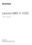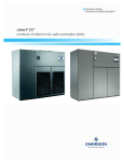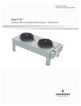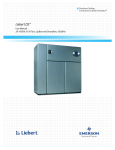
1
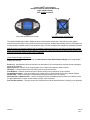
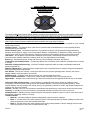
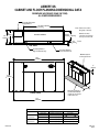
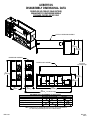
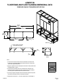
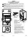
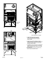
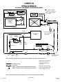
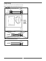
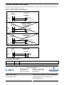
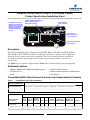
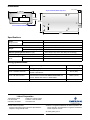
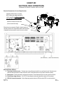
Liebert Products & Service World Headquarters United States 1050 Dearborn Drive, P.O. Box 29186 Columbus, Ohio 43229 Telephone: 614-888-0246 Facsimile: 614-841-6973 Europe Via Leonardo Da Vinci 8 Zona Industriale Tognana 35028 Piove Di Sacco Italy Telephone: 39-049-9719-111 Facsimile: 39-049-5841-257 Asia 29/F, The Orient Square Building F. Ortigas Jr. Road, Ortigas Center Pasig City 1605 Philippines Telephone: 63 2 687 6615 Facsimile: 63 2 730 9572 Liebert DS PG1 Job Name T-MOBILE - DENVER, CO - AIR Model Quantity Date Invoice # Purchaser P.O. # Tag # Submitted By DS105AUA1EI / MCL220E8AEA997 2 (Two) / 2 (Two) December 5, 2014 SWSG 14-068-H01-LIE-P1 Liebert Capitol Office – Jim Grant Rev 10/10 LIEBERT DS ENGINEERING SPECIFICATION SHEET AIR-COOLED SYSTEMS Project Name: Date: Reference No.: Submitted By: T-MOBILE - DENVER, CO December 5, 2014 Q02192366 Liebert Capitol Office – Jim Grant Model Number: DS105AUA1EI Condenser Model Number: MCL220E8AEA997 Quantity: 2 Quantity: 2 ELECTRICAL SUPPLY REQUIREMENTS Liebert Room Unit: 460 Volt, 3 Phase, 60 Hertz, 83.7 Full Load Amps, 97.4 Wire Sizing Amps, 110.0 Over-Current Protection Device, 65,000 Amps RMS Short Circuit Current Rating Air-Cooled Condenser Unit: 460 Volt, 3 Phase, 60 Hertz, 11.2 Full Load Amps, 11.9 Wire Sizing Amps, 15.0 Over-Current Protection Device CABINET SECTION • Downflow Unit • Colors: Main: Z-0420 (IBM Charcoal) NET CAPACITY DATA • 75ºF (23.9) – 60.1ºF (15.6ºC) • 45% RH • Total Capacity: 313,300 BTU/hr (91.8 kW) • Sensible Capacity: 243,700 BTU/hr (71.4 kW) EVAPORATOR FAN SECTION • Electronically Commutated (EC) Plug Fan Operates Under Floor • Fan Motor Horsepower: 3.6 (2.7 kW) per Motor, 3 (Three) Motor per Unit • Air Volume: 13,700 CFM (23,276 CMH) • External Static Pressure: 0.2 Inches of Water (75 Pa) • Elevation: 5,280 Feet (1,609 meters) • Module Dry Weights: 2,774 lbs (1,258 kg) FILTER SECTION (** Efficiency based on ASHRAE Standard 52.2) • 4 inch Merv 8 Filters HUMIDIFIER SECTION • Infrared Humidifier Capacity: 22 lbs/hr (10 kg/hr) REHEAT SECTION # Includes Fan Motor • 3-stage Electric Reheat Capacity: 102,400 BTU/hr (30 kW) CONTROL SECTION • Microprocessor with Large Graphic Display • Display Language English • Low Voltage Terminal Package • Local Alarms Terminals located on wire raceway. All alarms require N.O. contacts. 24 Volt A.C. • Main Fan Overload • Compressor Overload Alarm Terminal 24* • Local Alarms (4 max) 1 ______ Terminal 50* 2 ______ Terminal 51* 3 ______ Terminal 55* 4 ______ Terminal 56* ADDITIONAL EQUIPMENT • Dual Float Condensate Pump • Digital Scroll Compressors • R-407C Refrigerant (charges and supplied by others) • Locking Disconnect Switch • Reheat and Humidifier Lockout PG2 Rev 10/10 • • • • • • • • Smoke Sensor 36" Floor Stand IS-UNITY-DP Intellislot Unity Card; Qty; 1 (One) Per Unit LT410, Point Leak Sensors; Qty; 2 (Two) Per Unit Damper motor control circuit. Qty: 1 (One) Per Unit 1 (One) Year Limited Labor Warranty 2nd Years Parts Extended Warranty 2nd Year Compressor Extended Warranty AIR-COOLED CONDENSER SECTION STANDARD FEATURES • Microchannel aluminum coil(s) • Integrated fan motor/blade/guard assembly • Electronic control of fan speed • Factory wired and mounted NEMA 3R electrical panel/box • Fused, locking and lockable electrical disconnect switch • Variable fan speed motors CABINET • Bright aluminum exterior panels • Bright aluminum NEMA 3R electrical panel • Bright aluminum legs CONTROL/COMMUNICATION/FAN • Variable speed EC fans • Premium electronic control & communication board • CANbus connection terminals for communication with iCOM REFRIGERANT & CIRCUITS • R-407C (R-22) set points • Dual refrigerant circuits OPTIONAL FEATURES • Liebert Lee-Temp receivers and head pressure controls for field installation • Variable speed fans programming for Liebert Lee-Temp system PG3 Rev 10/10 Performance Results - Air Cooled - Performance Analysis Page 1 of 1 Liebert Rating System Project Name: T-MOBILE DENVER, CO Customer Name: SWSG Sales Rep. Name: JUVELITO CACA Office Name: Liebert North America HQ Phone Number: Liebert DS Model DS105AU; Air Cooled Manufacturer: Unit Power Supply: Refrigerant: Internal Filter Class: Unit Airflow ESP: Liebert North America 460/3/60 R407C Merv 8 Std. - 4 inch (102 mm) 13700 cfm 0.2 "WG Condenser Spec.sheet output date: Width: Depth: Height: Weight: Altitude: Compressor Liebert North America Model: MCL110x8 Control Type: Premium Condenser Type: Microchannel Design Ambient: 95 °F Quantity: 1 Airflow: 20878 CFM Power supply: 460/3/60 Sound Level: Std Condenser Fan RPM: 980 Manufacturer: Model: Compressor Type: Power Supply: Power Input: Compressor's COP: Quantity: Manufacturer: 05-Dec-14 132 " 35 " 76 " 3040 lbs 5280 ft Cooling Coil Carlyle 06DA537 SemiHermetic 460/3/60 16.4 2.76 2 Manufacturer: Model: Fin Type: Number of Rows: Fins per Inch: Face Area: Surface Area: Liebert North America 04R12LAU Lanced 3 12 32.29 sq.ft. 2365.27 sq.ft. Cooling Fans Quantity of Fans: 3 EC Plug Fan Type: under floor Power Supply: 460/3/60 Quantity of Motors: 3 Performance - Mechanical Cooling Leave Leave Total System Total Sens Total Air Enter Enter Enter Unit System System Evap Cond Amb Fan Wet Comp Power Dry Cool Cool Heat Air Face Cooling Dry Wet Rel SCOP NSCOP Temp Temp Temp kW Bulb Bulb Power Input Rej Cap Cap Vel Step Bulb Bulb Humid Vol W/W W/W ºF ºF ºF kW kW ºF ºF kBTUh kBTUh kBTUh CFM FPM % ºF ºF 4.0 75 60.1 45.0 13700 424.2 95 313.3 243.7 444.7 42.9 129.2 54.8 51.1 32.70 41.59 1.72 1.72 5.98 Blower: WARNING: The calculated SCFM is outside the recommended limits of (12600 - 15500) cfm.. Default blower used. 1) Capacity shown has been reduced by fan motor heat (net). 2) Coil airflow is reduced by a bypass of 0.73% of total unit airflow 3) Test method as defined by ASHRAE 127-2007 4) Capacity Tolerance is 5% © 2014 Liebert Corporation. All Rights Reserved P5 http://lrs.liebert.com/Secured/P7a.aspx v. 1.0.12.4 12/6/2014 Liebert iCOM® Control System Intelligent Communications & Monitoring Large Graphic Display (Unit or Wall-mounted) Large Graphic Display shown in unit bezel Large Graphic Display for Wall-Mounting The Liebert iCOM® Large Graphic Display shall be microprocessor based with a 320x240 dot matrix graphic monitor with control keys for user inputs mounted in an ergonomic, aesthetically pleasing housing. The display and housing shall be viewable while the unit panels are open or closed. All parameter changes are password protected. Wall-Mounted Large Graphic Displays shall be capable of being mounted on a wall and are provided with a power supply. Wall-mounted displays can be added to a Unit-to-Unit network and remotely located from the cooling unit(s) to provide convenient monitoring and control capabilities. Large Graphic Display only features: The Large Graphic Display provides all of the same features of the Small Graphic Display, plus Large Graphic Display only features. Event Log – Automatically stores the last 400 unit and system (U2U communication required) events (messages, warnings, and alarms) Spare Parts List - shows a list of key spare parts, their quantity and respective parts numbers Unit Diary - A free field area where unit history may be stored for reference View Network – Shows a summarized view of all the cooling units connected on a U2U network Centralized Operation – View and configure any cooling unit on a U2U network from a Large Graphic Display System View – View the averages of all operations being performed on the U2U network Active Alarms on Status Screen – Last two unit/system events are displayed at the bottom of the Status Screen for rapid identification of critical events without having to enter submenus Full Text Descriptions – The large screen size eliminates the need for abbreviated text, simplifying user operation DPN000794 REV 4/09 REV 2 Liebert iCOM® Control System Intelligent Communications & Monitoring Small Graphic Display (Unit-mounted only) Small Graphic Display shown in unit bezel The Liebert iCOM® Small Graphic Display shall be microprocessor based with a 128x64 dot matrix graphic monitor with control keys for user inputs mounted in an ergonomic, aesthetically pleasing housing. The display and housing shall be viewable while the unit panels are open or closed. All parameter changes are password protected. Small Graphic Display Features (additional features available with Large Graphic Display): Temperature Control – Precision temperature control is maintained while maximizing efficiency based on a user entered setpoint and tolerance. Humidity Control – The dewpoint level of the room is monitored and controlled based on a user specified Relative Humidity setpoint and tolerance. Various Control Types – Selectable Proportional, PI (proportional-integral), PID (proportional-integral-derivative), Intelligent control types for supply or return temperature; Relative, Compensated, or Predictive humidity control types. These control types have been developed to maximize component life and maintain precise environmental control. Unit Alarms – All unit alarms are annunciated, displayed on the screen, automatically recorded in the event log, communicated to available IntelliSlot monitoring cards, and a red light flashes on the display Event Log – Automatically stores the last 400 unit-only events (messages, warnings, and alarms). Temperature and Humidity Graphs – Provides a graphical view of historical room conditions, selectable from 8 minutes to 16 days Automatic Component Sequencing – runtimes of multiple components within a unit are automatically balanced to extend component life Wellness / Maintenance – Monitors system components to warn of potential issues in advance (helps avoid unplanned downtime) and prolong component life Auto Restart – After a loss of power, a cooling unit will return to is previous operating status. Cooling units can be stagger started to minimize system current draw. IntelliSlot Cards – IntelliSlot cards allow for external unit communication and control Service Contact Information – Local service or sales contact information can be conveniently stored Upgradeable – Multiple units connected through a Unit-to-Unit network can be upgraded simultaneously or cascaded. Unit-to-Unit (U2U) Communication – Communication via private Ethernet network allows for advanced control functionality (Teamwork modes, sharing sensor data, Standby Rotation, Lead-Lag, and Cascade operation). Small Graphic Displays can only configure the cooling unit they are physically connected to, while Large Graphic Displays can configure any unit on the network. Cascade – Standby units on a U2U network are automatically activated if active unit(s) cannot control the environment Lead-Lag – A standby unit on a U2U network is automatically activated if an alarm occurs in an active unit Standby Rotation – Standby units are rotated through a U2U network to balance system run hours. Units can be set to automatically rotate daily, weekly, or monthly Teamwork modes • Mode No – Units share data but operate independently using local sensor readings • Mode 1 – All units perform the same operation with the same intensity based on sensor readings from the entire network; typically for rooms with balanced heat loads • Mode 2 – All units perform the same operation with varying intensity based on sensor readings from the entire network; typically for rooms with un-balanced heat loads DPN000793 REV 4/09 REV 1 LIEBERT DS CABINET AND FLOOR PLANNING DIMENSIONAL DATA DOWNFLOW AIR COOLED 105kW (30 TONS) ALL COMPRESSOR MODELS Secondary Refrigerant Piping Entrance 102 13/16" Opening 2611mm Notes: Filters are accessible through top of unit only. 33" 838mm 24 3/8" 619mm AIR INLET OPENING 35" 889mm Opening 3/4" 19mm Downflow electrical connections can be made from top or bottom of unit. Bezels TOP VIEW Secondary Entrance High Volt Connection(s) Secondary Entrance Low Volt Connections Minimum required for filter replacement 132" 3353mm 5" (127mm) 76" 1930mm 34" 864mm Shaded area indicates a recommended minimum clearance be provided for component access. FRONT VIEW 131" 3327mm DRY WEIGHT lb(kg) APPROXIMATE Unit with: Semi-Hermetic Compressors Scroll Compressors DPN001012 Model Fan type 105 Forward-curved Fans 105 EC Fans Air Cooled Dual Cool Air Cooled Dual Cool 3040 (1382) 3400 (1545) 2920 (1327) 3280 (1491) 2774 (1258) 3134 (1422) 2654 (1204) 3014 (1367) REV 08/12 REV 4 LIEBERT DS DISASSEMBLY DIMENSIONAL DATA DOWNFLOW AIR COOLED 105kW (30TONS) SEMI-HERMETIC COMPRESSOR MODELS FORWARD-CURVED AND EC FANS FILTER & ELECTRIC BOX ASSEMBLY 39" 991mm 41 11/16" 1059mm COMPRESSOR ASSEMBLY 76" 1930mm Assembled Height BLOWER & COIL ASSEMBLY 76" 1930mm 59 7/16" 1510mm 37" 940mm 33" 838mm 105" 2667mm 26" 660mm 131" 3327mm Assembled Length DRY WEIGHT lb(kg) APPROXIMATE (Includes Panels) Forward-curved Fans EC Fans Air Cooled Dual Cool Air Cooled Dual Cool COMPRESSOR ASSEMBLY 950 (432) 950 (432) 950 (432) 950 (432) FILTER & ELECTRIC BOX ASSEMBLY 270 (123) 270 (123) 270 (123) 270 (123) BLOWER & COIL ASSEMBLY 1820 (827) 2180 (991) 1560 (708) 1915 (870) NOTE: Drawing views are simplified with panels removed to show overall dimensions. See disassembly and handling instructions in installation manual. DPN001057 REV 08/12 REV 2 LIEBERT DS FLOORSTAND AND FLOOR PLANNING DIMENSIONAL DATA DOWNFLOW 105kW (30 TONS) MODELS WITH EC FANS 132 1/2" 3366mm (with feet) 25" 635mm 131" 3327mm 34 1/2" 876mm (with feet) 33" 838mm 74" 1880mm 1" 25mm TYP. SEE NOTE 4 Gussets supplied on floorstands 12" (305 mm) tall and greater. 7/8" 23mm 3" 76mm A* 35" 889mm OVERALL DEPTH NOTE: 1) This floor stand should be used when EC fans are intended to be lowered under a raised floor. The standard Liebert DS floor stand can be used “if” the fans are to remain in their original raised position. 2) Right side of paneled unit is flush with right side of floorstand. All other paneled sides overhang floorstand 1" (25mm). 3) The floor stand used with EC units is not symmetrical and its orientation to the Liebert DS is critical for lowering the EC fans. Unless the floor stand is installed in the correct position, the blowers will not lower into the floor stand. Height in ( mm ) A* 24 (610) 30 (762) 36 (914) 42 (1067) 48 (1219) 4) Jack and jack support are shipped loose and are intended to be placed into position under each fan and utilized to lower or raise that fan as needed. *Leveling feet are provided with u 1-1/2” (38mm) adjustment from nominal height “A”. DPN002152 REV 07/10 REV 0 LIEBERT EC FAN REMOVAL PROCEDURE DOWNFLOW MODELS WITH EC FANS WARNING - RISK OF ELECTRIC SHOCK AND HIGH SPEED ROTATING FAN BLADES! CAN CAUSE INJURY OR DEATH! DISCONNECT ALL LOCAL AND REMOTE ELECTRIC POWER SUPPLIES AND VERIFY THAT FAN BLADES HAVE STOPPED ROTATING BEFORE WORKING WITHIN. WARNING - RISK OF EXTREMELY HEAVY FAN MODULES DROPPING DOWNWARD SUDDENLY! CAN CAUSE INJURY OR DEATH! SUPPORT FAN MODULES BEFORE REMOVING MOUNTING HARDWARE. USE CAUTION TO KEEP BODY PARTS OUT OF FAN MODULE PATHWAY OF MOVEMENT DURING REMOVAL. ONLY QUALIFIED PERSONNEL SHOULD WORK ON THIS EQUIPMENT. FAN MODULES WEIGH IN EXCESS OF 100 LBS. (45.4 KG) EACH. LIEBERT CW041 UNIT SHOWN WITH LIEBERT 24" FLOORSTAND. CUSTOMER UNIT MAY APPEAR SLIGHTLY DIFFERENT. READ USER MANUAL SL-18057 AND INSTRUCTION SHEET 195788 BEFORE RE-POSITIONING THE FAN MODULES. 1 3 TABS 2 1 DETAIL A JACK LOCATION B B 3 TOOLS NEEDED: 3 -1/2" HEX SOCKET & WRENCH -FACTORY SUPPLIED JACK, CRANK AND JACK SUPPORT -CABLE TIE CUTTER -FIELD SUPPLIED FAN REMOVAL DEVICE CAPABLE OF SUPPORTING 100 LBS. (45.4 KG). A FLOORSTAND PARTIALLY HIDDEN 1. REMOVE PANELS FROM FRONT OF UNIT. 2. FOR EASE OF FAN REMOVAL, REMOVAL OF HUMIDIFIER PAN IS RECOMMENDED. 3. IF FAN MODULE IS LOWERED INTO THE FLOORSTAND, POSITION THE FACTORY SUPPLIED JACK AND JACK SUPPORT UNDER THE FAN MODULE SO IT IS SAFELY SUPPORTED BEFORE REMOVING ANY HARDWARE. IF FAN MODULE IS IN THE "UP" POSITION, PROCEED TO STEP 6. NOTE: A PROPERLY POSITIONED JACK WILL BE CENTERED BETWEEN THE FIRST AND SECOND SET OF TABS ON THE JACK SUPPORT AS SHOWN IN DETAIL "A". HARDWARE 4 DPN001695 SECTION B-B HARDWARE 4 4. REMOVE HARDWARE USED TO RETAIN FAN MODULE IN THE LOWERED POSITION. RETAIN HARDWARE FOR FAN MODULE RE-INSTALLATION. NOTE: HARDWARE QUANTITY AND LOCATION WILL VARY DEPENDING ON UNIT. PAGE 1 OF 3 REV 08/10 REV 5 FRONT FRAME CHANNEL 5 6 6 7 FRONT FRAME CHANNEL REAR FRAME CHANNEL RIGHT SIDE PANEL NOT SHOWN 5. USING THE FACTORY SUPPLIED JACK AND CRANK, SLOWLY RAISE THE FAN MODULE UNTIL THE FAN MOTOR CLEARS THE FRONT FRAME CHANNEL. 6. INSERT FIELD SUPPLIED FAN REMOVAL DEVICE UNDER FAN MODULE. FIELD SUPPLIED FAN REMOVAL DEVICE SHOULD REST SECURELY ON THE FRONT AND REAR FRAME CHANNELS. 7. DISCONNECT HIGH VOLT AND LOW VOLT FAN MOTOR WIRING FROM FAN MOTOR ELECTRIC COMPONENT INSIDE OF ELECTRIC PANEL. CAREFULLY CUT CABLE TIES AS NEEDED. NOTE: REFER TO UNIT ELECTRICAL SCHEMATIC FOR SPECIFIC WIRE ATTACHMENT POINTS. 6 DPN001695 6 PAGE 2 OF 3 REV 08/10 REV 5 8. SLIDE FAN MODULE OUT OF UNIT. 9. FOR FAN MODULE RE-INSTALLATION, FOLLOW PREVIOUS STEPS IN REVERSE ORDER. REMOVE FIELD SUPPLIED FAN REMOVAL DEVICE BEFORE RESUMING UNIT OPERIATION. 8 RIGHT SIDE PANEL NOT SHOWN DPN001695 PAGE 3 OF 3 REV 08/10 REV 5 LIEBERT EC FAN LOWERING PROCEDURE & BLOCK OFF PANEL KIT INSTALLATION DOWNFLOW MODELS WITH EC FANS WARNING -RISK OF ELECTRIC SHOCK AND HIGH SPEED ROTATING FAN BLADES! CAN CAUSE INJURY OR DEATH! DISCONNECT ALL LOCAL AND REMOTE ELECTRIC POWER SUPPLIES AND VERIFY THAT FAN BLADES HAVE STOPPED ROTATING BEFORE WORKING WITHIN. WARNING - RISK OF FAN MODULES DROPPING DOWNWARD SUDDENLY! CAN CAUSE INJURY OR DEATH! SUPPORT FAN MODULES BEFORE REMOVING MOUNTING HARDWARE. USE CAUTION TO KEEP BODY PARTS OUT OF THE FAN MODULES PATHWAY OF MOVEMENT DURING REPOSITIONING. ONLY QUALIFIED PERSONNEL SHOULD WORK ON THIS EQUIPMENT. LIEBERT CW041 UNIT SHOWN WITH LIEBERT 24" FLOORSTAND. CUSTOMER UNIT MAY APPEAR DIFFERENT. READ USER MANUAL SL-18057 AND INSTRUCTION SHEET 195788 BEFORE RE-POSITIONING THE FAN MODULES. 1 3 2 TABS 1 DETAIL A JACK LOCATION B B SECTION NOT SHOWN TOOLS NEEDED: 1/2" HEX SOCKET & WRENCH FACTORY SUPPLIED JACK, CRANK AND JACK SUPPORT CABLE TIE CUTTER SECTION NOT SHOWN 3 A 3 LOWERING PROCEDURE (24" FLOOR HEIGHT MINIMUM): 1. REMOVE THE MIDDLE AND BOTTOM PANELS FROM THE FRONT OF THE UNIT. 2. FOR EASE OF FAN LOWERING, REMOVAL OF THE HUMIDIFIER PAN IS RECOMMENDED. FAN DECK 5 5 4 "Z" BRACKET SECTION B-B "Z" BRACKET WIRING LOOP TOP VIEW OF FAN DECK DPN002037 PAGE 1 OF 3 3. POSITION THE FACTORY SUPPLIED JACK AND JACK SUPPORT UNDER THE FAN MODULE TO BE LOWERED. USING THE CRANK, RAISE THE JACK TO SAFELY SUPPORT THE FAN BEFORE REMOVING ANY HARDWARE. NOTE: A PROPERLY POSITIONED JACK WILL BE CENTERED BETWEEN THE FIRST AND SECOND SET OF TABS ON THE JACK SUPPORT. 4. CUT & REMOVE THE CABLE TIE THAT RETAINS THE WIRING LOOP TO THE BLOWER MOUNTING PLATE. ALL OTHER CABLE TIES THAT ROUTE THE FAN WIRING SHOULD REMAIN INTACT. 5. REMOVE THE SIX HEX-HEAD SCREWS AND "Z" BRACKETS USING A 1/2" HEX SOCKET OR WRENCH. RETAIN HARDWARE FOR LATER STEPS. "Z" BRACKETS NOT PRESENT ON LIEBERT DS, CW146 AND CW181. REV 7/10 REV 3 C C 6 FAN MODULE RESTING ON FRAME 6 6. USING THE FACTORY SUPPLIED JACK AND CRANK, LOWER THE FAN MODULE UNTIL IT RESTS ON THE FRAME OF THE UNIT. USE CAUTION TO PREVENT DAMAGE TO THE FAN WIRE HARNESS. 6 7. CW026, CW038, CW041, CW076 THRU CW114 MODELS: USING THE HARDWARE REMOVED IN STEP 5, RE-INSTALL "Z" BRACKETS WITH HEX-HEAD SCREWS TO RETAIN FAN MODULE IN THE FULLY LOWERED POSITION. 7 7 "Z" BRACKETS CW051 AND CW060 MODELS: USE THE HEX-HEAD SCREWS REMOVED IN STEP 5 TO SECURE THE FAN MODULE DIRECTLY TO THE CENTER FRAME SUPPORT. SCREW CLEARANCE HOLES ARE PROVIDED IN THE FAN MODULE. THE "Z" BRACKETS WILL ONLY BE USED TO SECURE THE FAN AT THE OUTTER ATTACHMENT POINT. LIEBERT DS, CW146 AND CW181 MODELS: USE THE HEX HEAD SCREWS REMOVED IN STEP 5 TO SECURE THE FAN MODULE DIRECTLY TO THE FRAME. SCREW CLEARANCE HOLES ARE PROVIDED IN THE FAN MODULE. SECTION C-C FAN DECK AND SIDE PANELS NOT SHOWN IN THIS VIEW NOTE: NOT ALL HARDWARE REMOVED IN STEP 5 WILL BE USED TO RETAIN FANS IN LOWERED POSITION. 8. REPEAT STEPS 3-7 TO LOWER REMAINING FAN MODULE(S) IF PRESENT. NOTE: THE FANS MUST BE OPERATED IN EITHER THE FULLY RAISED POSITION OR FULLY LOWERED POSITION. NO OTHER COMBINATION OF FAN POSITIONING IS SUPPORTED. DPN002037 PAGE 2 OF 3 REV 7/10 REV 3 LIEBERT DS PRIMARY CONNECTION LOCATIONS DOWNFLOW AIR COOLED 105kW (30 TONS) ALL COMPRESSOR MODELS WITH EC FANS A A FRONT VIEW NOTE: Drawing not to scale. Tolerance on all piping dimensions is ± 1/2" (13mm). ALL DIMENSIONS FROM REAR CORNER OF UNIT INCLUDING PANELS SECTION A-A X O Y G1 G2 R 4" 102mm L1 L2 16 7/16" 418mm 35" 889mm BLOWER OUTLET ECR ECS E1 CD E2 B1 HUM LV1 LV2 LV3 FRONT OF UNIT 132" 3353mm POINT R L1 L2 G1 G2 DESCRIPTION REFRIGERANT ACCESS LIQUID LINE SYSTEM 1 LIQUID LINE SYSTEM 2 HOT GAS DISCHARGE 1 HOT GAS DISCHARGE 2 X 109" (2769mm) 121-3/4" (3092mm) 118-1/8" (3000mm) 118-1/4" (3004mm) 115-5/8" (2937mm) 15-3/4" 16-3/4" 16-3/4" 14-1/4" 14-1/4" Y (400mm) (425mm) (425mm) (362mm) (362mm) CONNECTION SIZE / OPENING 16-7/16" (418mm) X 4" (102mm) 5/8" CU SWEAT 5/8" CU SWEAT 1-1/8" CU SWEAT 1-1/8" CU SWEAT CONDENSATE DRAIN 87-3/8" (2220mm) 31" (787mm) 3/4" FPT (infrared humidifier or no humidifier)* W/ OPTIONAL PUMP 83-13/16" (2129mm) 30" (762mm) 1/2" CU SWEAT HUM HUMIDIFIER SUPPLY LINE 85-5/16" (2167mm) 32-1/2" (825mm) 1/4" CU SWEAT ECS ** ECON-O-COIL SUPPLY 101-7/8" (2588mm) 29" (737mm) 2-5/8" CU SWEAT ECR ** ECON-O-COIL RETURN 94-9/16" (2402mm) 29" (737mm) 2-5/8" CU SWEAT CONSULT FACTORY HS HOT WATER REHEAT SUPPLY CONSULT FACTORY HR HOT WATER REHEAT RETURN E1 ELECTRICAL CONN. (HIGH VOLT) 98-1/8" (2492mm) 31" (788mm) 2-1/2" E2 ELECTRICAL CONN. (HIGH VOLT) 91" (2311mm) 31" (788mm) 2-1/2" LV1 ELECTRICAL CONN. (LOW VOLT) 2" (51mm) 29" (737mm) 7/8" LV2 ELECTRICAL CONN. (LOW VOLT) 2" (51mm) 30-7/8" (784mm) 7/8" LV3 ELECTRICAL CONN. (LOW VOLT) 2" (51mm) 32" (813mm) 7/8" B1 BLOWER OUTLET 4-1/2" (114mm) 33" (838mm) 77-3/8" (1965mm) X 30" (762mm) CD * Field pitch Condensate Drain line a minimum of 1/8" (3.2 mm) per foot (305 mm). All units contain a factory installed condensate trap. Do not trap external to the unit. Drain line may contain boiling water. Select appropriate drain system materials. The drain line must comply with all local codes. ** Supplied on Dual Cooling systems only (4 piping system). DPN002154 REV 07/10 REV 0 LIEBERT DS PIPING SCHEMATIC AIR COOLED SEMI-HERMETIC COMPRESSOR MODELS Check Valve Relief Valve Service Valve LIQUID RETURN OPTIONAL SUB-COOLING COIL OPTIONAL SUB-COOLING COIL Head Pressure Control Valve LEE-TEMP RECEIVER Inverted Trap on discharge & liquid lines to extend above base of coil by a minimum of 7 1/2" (190mm). CONDENSER COIL (LEE-TEMP) CONDENSER COIL (FAN SPEED or VFD) OPTIONAL FIELD INSTALLED FUSIBLE PLUG HOT GAS DISCHARGE LEE-TEMP LIQUID Sensing Bulb Cylinder Unloader(s) Service Valve Muffler COMPRESSOR For rises over 25ft. (7.6m), trap every 20ft. (6m) or evenly divided* EVAPORATOR COIL SUCTION Service Valve External Equalizer Field installed relief valve(s) required for 50 Hz EU CE units rated maximum 480 PSIG (33 Bar). *Isolation Valve **Muffler Check Valve HOT GAS DISCHARGE Expansion Solenoid Valve Valve Sight Glass LIQUID RETURN Filter Drier *Isolation Valve Trap at base of risers over 5ft. (1.5m)* NOTE: TWO REFRIGERATION CIRCUITS PROVIDED. SINGLE REFRIGERATION CIRCUIT SHOWN FOR CLARITY. * Components are not supplied by Liebert but are required for proper circuit operation and maintenance REFRIGERANT PIPING FIELD PIPING SERVICE / SCHRADER (ACCESS) CONNECTION NO VALVE CORE SERVICE / SCHRADER (ACCESS) CONNECTION WITH VALVE CORE ** Components supplied by Liebert and must be field installed (70kW, 77 kW & 105kW models only) NOTE: SCHEMATIC REPRESENTATION SHOWN. DO NOT USE FOR SPECIFIC CONNECTION LOCATIONS. DPN000797 SHEET 1 OF 1 REV 06/14 REV 7 LIEBERT DS AND DSE ELECTRICAL FIELD CONNECTION DESCRIPTIONS DS, DA080, AND DA085 MODELS STANDARD ELECTRICAL CONNECTIONS 1) Primary high voltage entrance - 2.50” (64mm); 1.75” (44mm); 1.375” (35mm) diameter concentric knockouts located in bottom of box 2) Secondary high voltage entrance - 2.50” (64mm); 1.75” (44mm); 1.375” (35mm) diameter concentric knockouts located in top of box 3) Primary low voltage entrance - Quantity (3) 1.375” (35mm) diameter knockouts located in bottom of unit 4) Secondary low voltage entrance - Quantity (3) 1. 375” (35mm) diameter knockouts located in top of box 5) Three phase electrical service - Terminals are on main fuse block (disregard if unit has optional disconnect switch). Three phase servic e not by Liebert. 6) Earth ground - Terminal for field supplied earth grounding w ire. Earth grounding required for Liebert units. 7) Remote unit shutdown - Replace existing jumper betw een terminals 37 & 38 w ith field supplied normally closed switch having a minimum 75VA, 24VAC rating. Use field supplied Class 1 wiring. 8) Customer alarm inputs - Terminals for field supplied, normally open contacts, having a minimum 75VA, 24VAC rating, betw een terminals 24 & 50, 51, 55, 56. Use field supplied Class 1 wiring. Terminal availability varies by unit options. 9) Common alarm - On any alarm, normally open dry contact is closed across terminals 75 & 76 for remote indication. 1 AMP, 24VAC max load. Use Class 1 field supplied wiring. 10) Heat rejection interlock - On any call for compressor operation, normally open dry contact is closed across terminals 70 & 71(circuit 1), 230 (circuit 2) to heat rejection equipment. 1 AMP, 24VAC max load. Use Class 1 field supplied wiring. When DS unit is paired with a Liebert MC series condenser, remove jumper between terminal 71 and terminal 230. Three w ires must connect terminals 70, 71 and 230 of the indoor unit to terminals 70, 71 and 230 of the Liebert MC series condenser. Liebert DSE units must be connected to Liebert MC series condenser with premium control. It is required that the jumper betw een terminal 71 and terminal 230 be remov ed. Three wires must connect terminals 70, 71, and 230 of the indoor unit to terminals 70, 71 and 230 of the Liebert MC series condenser. CANBUS ELECTRICAL CONNECTIONS 11) CANBus Connector– Terminal block w ith terminals 49-1 (CAN-H) and 49-3 (CAN-L) + SH (shield connection). The terminals are used to connect the CANBus communic ation cable (prov ided by others) from the indoor unit to the Liebert Mic rochannel Condenser – Premium Model and Optional PRE Unit. 12) CANBus Cable – CANBus cable prov ided by others to connect to the outdoor condenser. Cable must have the follow ing specifications: a) Conductors – 22-18AWG stranded tinned copper b) Tw is ted Pair c) Braided shield or Foil shield with Drain Wire d) Low Capacitance – 15pf/ft or less e) UL Approved Temperature rated to 75°C f) UL Approved Voltage rated to 300V g) UV and Mois ture resis tant if not prov ided in conduit. h) Plenum rated – NEC ty pe CMP (if required by national or local codes.) OPTIONAL ELECTRICAL CONNECTIONS 13) Unit factory installed disconnect switch, Fuse Block and Main Fuses – Two ty pes of disconnect switches are available – “Non-Locking” and “Locking”. The “NonLocking Type” consis ts of a non-automatic molded case switch operational from the outside of the unit. Access to the high voltage electric panel compartment can be obtained with the switch in either the “on” or “off” position. The “Locking Type” is identical except access to the high voltage electric panel compartment can be obtained only with the switch in the “off” position. Units with fused disconnects are provided with a defeater button that allows access to the electric al panel w hen pow er is on. The molded case sw itc h disconnect models contain separate main fuses. Units w ith fused dis connect have main fuses within the dis connect. Only fused disconnects are used on dual disconnect options. 14) Secondary disconnect switch and earth ground 15) Three phase electrical service - Terminals are on top of disconnect sw itc h. Three phase service not by Liebert. 16) Smoke sensor alarm - Factory w ired dry contacts from smoke sensor are 91-common, 92-NO, and 93-NC. Supervised contacts, 80 & 81, open on sensor trouble indication. This smoke sensor is not intended to function as, or replace, any room smoke detection system that may be required by local or national codes. 1 AMP, 24VAC max load. Use Class 1 field supplied wiring. 17) Reheat and hum idifier lockout - Remote 24VAC required at terminals 82 & 83 for lockout of reheat and humidifier. 18) Condensate alarm (with condensate pump option) - On pump high water indic ation, normally open dry contact is closed across terminals 88 & 89 for remote indic ation. 1 AMP, 24VAC max load. Use Class 1 field supplied w iring. 19) Remote humidifier - On any call for humidific ation, normally open dry contact is closed across terminals 11 & 12 to signal field supplied remote humidifier. 1 AMP, 24VAC max load. Use Class 1 field supplied wiring. 20) Auxiliary cool contact - On any call for econ-o-coil operation, normally open dry contact is closed across terminals 72 & 73 on dual cool units only . 1 AMP, 24VAC max load. Use Class 1 field supplied wiring. OPTIONAL LOW VOLTAGE TERMINAL PACKAGE CONNECTIONS 21) Remote unit shutdown - Two additional contact pairs av ailable for unit shutdown (labeled as 37B & 38B, 37C & 38C). Replace jumpers with field supplied normally closed sw itc h hav ing a minimum 75VA, 24VAC rating. Use field supplied Class 1 wiring. 22) Common alarm - On any alarm, tw o additional normally open dry contacts are closed across terminals 94 & 95 and 96 & 97 for remote indic ation. 1 AMP, 24VAC max load. Use Class 1 field supplied wiring. 23) Main fan auxiliary switch - On closure of main fan contactor, normally open dry contact is closed across terminals 84 & 85 for remote indic ation. 1 AMP, 24VAC max load. Use Class 1 field supplied wiring. 24) LiquiTect shutdown and dry contact - On LiquiT ect activation, normally open dry contact is closed across terminals 58 & 59 for remote indication (LiquiTect sensor ordered separately ). 1 AMP, 24VAC max load. Use Class 1 field supplied wiring. DPN000807 PAGE1 of 3 REV DATE 05/14 REV 9 LIEBERT DS AND DSE ELECTRICAL FIELD CONNECTIONS Intellislot Housing DS, DA080, AND DA085 UPFLOW AND DOWNFLOW MODELS SINGLE MOLDED CASE SWITCH DISCONNECT WITH MAIN FUSES 2 OVERCURRENT PROTECTION DEVICES 15 A B C D 4 Alternate Location P64 6 60 Hz CONTACTORS P67 CONTACTORS, RELAYS, & OVERLOAD PROTECTORS 13 E 5 1 6 Note: Typical orientation of components shown. Component location varies by option and unit size. 17 18 9 16 22 3 DS DOWNFLOW DA080/085 UPFLOW AND DOWNFLOW LOW VOLT SECTION 19 CAUTION: 82 83 88 89 75 76 94 95 96 97 91 92 93 80 81 11 12 UPFLOW 3 B A 24 23 58 59 84 85 21 7 10 8 Risk of broken or shorted low volt wiring. Field installed low volt wiring must be routed with loop as shown to allow electric box to swing. 20 37C38C37B38B 37 38 24 50 51 55 56 70 71 230 72 73 C D 49 3 49 1 SH 11 12 E Item 12 Installation Conditions 1. Follow all local installation codes. 2. Do not run CAN cables in same conduit, raceway, or chase as high voltage wires (120-600V). 3. Separate high volt wires from CAN wires by 12 inches. 4. For runs greater than 350ft(107m), contact Liebert factory. DPN000807 POINT OF HINGED LOW VOLT ELECTRIC BOX DS UPFLOW LOW VOLTSECTION PAGE2 of 3 REV DATE 05/14 REV 9 LIEBERT® INTELLISLOT® UNITY PLATFORM CARDS Product Specification/Installation Sheet Liebert Intellislot Unity cards are a form, fit and function replacement for several existing Liebert Intellislot Web and 485 cards. RS-485 - Modbus RTU, BACnet MSTP, YDN23; Building Management System RJ-45-Ethernet—Trellis; Modbus TCP; BACnet IP; SNMPv1, v2c, v3; Liebert Protocol; HTTP; Building Management System; Network Management System Micro-USB AB (future release) IS-UNITY-DP Reset Button (Reboot or reset to factory defaults) Link 485 Activity Liebert Sensor Network (future release) Description The Liebert IntelliSlot Unity Platform brings SNMP, BACnet IP, BACnet MSTP, Modbus TCP, Modbus RTU, YDN23 and Web management capability to many models of Emerson Network Power’s power and cooling equipment. The cards employ Ethernet and RS-485 networks to monitor and manage a wide range of operating parameters, alarms and notifications. See Table 1 for equipment supported and Table 2 for communication protocols supported. Additional Features • SNMPv1, SNMPv2c and SNMPv3 with MIB-II support • DHCP per RFC2131/2132 • HTTP/HTTPS 1.1 • Remote firmware updates via a Web browser • BootP • IPv4 and IPv6 Compatibility With Other Emerson Products and Communication Protocols Table 1 Compatibility with Liebert equipment Compatible with: Liebert IntelliSlot Card ™ Liebert APM , Liebert APS , Liebert CRV™, Liebert CW™, Liebert Challenger 3000™ Liebert DCP™, Liebert Deluxe System/3™, Liebert DS™, Liebert DSE™, Liebert HPC™ Liebert HPC-S/M/R/W/Generic™, Liebert HPM™, Liebert NXC™, Liebert NXL™ *, Liebert NXR™, Liebert PCW™/PDX™, Liebert PeX™ *, Liebert XDC™, Liebert XDP™, Liebert XDP-Cray™ Liebert IS-UNITY-DP Liebert IS-UNITY-LIFE Table 2 ™ Liebert IntelliSlot card communication protocols Communication Protocol HTTP HTTPS Emerson Protocol Remote Service Delivery Protocol Liebert IS-UNITY-DP (IS-UNITY-DP) ✔ ✔ ✔ ✔ ✔ ✔ ✔ ✔ ✔ Liebert IS-UNITY-LIFE (IS-UNITY-LIFE) ✔ ✔ ✔ — — — — — — Liebert IntelliSlot Card (Part #) * Email SMS SNMP v1, v2c, v3 BACnet IP BACnet MSTP Modbus TCP Modbus RTU YDN23 * YDN23 supported only for Liebert PeX and Liebert NXL. 1 Dimensions Top of Liebert IntelliSlot Unity Card 3" (76mm) 1/2" (11mm) 1- 1/2" (38mm) 2-3/8" (60.3mm) Front of Liebert IntelliSlot Unity Card 4-3/4" (121mm) Specifications DC Inputs Power Requirements Power Consumption Dimensions - W x D x H: in. (mm) Shipping, lb. (kg) Ambient Operating Environment, °F (°C) • 7 (0.2) • 1.3 (0.6) • 32 to 104 (0 to 40); 10% to 90% RH (non-condensing) Ambient Storage Temperature, °F (°C) Communication Ports • 3.6W maximum • 2.97 x 5.2 x 1.45 (75.5 x 15 x 37) Net, oz. (kg) Weight • 7 to 12VDC • -4 to 140 (-20 to 60) Ethernet Communications RS-485 • RJ-45 • RJ-45 (RJ-45 to 2-Position Terminal Block Adapter) Wiring Specifications Maximum Wire Length Connection Supported Wire Type 10/100Mb/s Ethernet Connector Standard Category 5E Cable 328 ft. (100m) RJ-45 - One-Wire Connector Liebert® Integrated One-Wire Sensor Cable or 2m Cat 5E to Modular 1-Wire Sensor. 65.6 ft. (20m) RJ-45 - RS-485 Connector ADAPTER RJ45-2POS TERMINAL BLOCK EIA485 to 18-22 AWG Stranded & Shielded 18 AWG recommended Non Plenum - Belden 9461 Plenum - Belden 88761 3000 ft. (914m) Micro-USB AB Standard Micro-USB AB 16.4 ft. (5m) Liebert Corporation 1050 Dearborn Drive P.O. Box 29186 Columbus, OH 43229 Telephone: 1-800-877-9222 Facsimile: 1-614-841-6022 www.liebert.com © 2012 Liebert Corporation All rights reserved throughout the world. Specifications subject to change without notice. ® Liebert is a registered trademark of Liebert Corporation. All names referred to are trademarks or registered trademarks of their respective owners. SL-52646_REV4_06-14 2 LIEBERT LIQUI-TECT® 410 Point Leak Detection Sensor Product Specification Sheet Description The Liebert Liqui-tect 410 (LT410) provides a single-point detection of leaks. The point detection sensor has two gold-plated sensing probes to prevent corrosion resistance and to provide accurate readings. The LT410 constantly monitors points for leaks, internal faults and power failures and warns of any abnormal conditions. Mounting brackets allow for sensor height adjustment and leveling. The LT410 is the ideal solution for sensing leaks under a raised computer floor or air conditioning drip pans. Two independent outputs provide added flexibility with the capacity to signal both a local alarm panel and a remote building management system or external equipment, such as motorized water shut-off valves. The LT410 is also ideally suited for the following: Applications Locations • Glycol, Chilled Water Cooling • Large-Scale Network Control Centers • Mechanical Equipment Rooms • Data Centers • Sensitive Areas With Overhead Piping • Humidification Feed Water Piping • Condensate Pumps and Drains • Unit and Ceiling Auxiliary Drip Pans • Overhead Piping Troughs • Server Rooms - Closets • Unattended Remote Shelters • Industrial Process Control Rooms Dimensions - Top, Front & Side Views TOP VIEW FRONT VIEW SIDE VIEW 5.85" (148.5mm) 4.46" (113.2mm) Form-C relay outputs & power wiring connection 6.35" (161.2mm) Adjustable probe height 0.0–0.5" (0.0–12.7mm) Shipping weight: 2 Ibs (0.9 kg) Mounting holes: #8 screws 1 2.25" (57.2mm) Specifications Placement on Subfloor Under Cooling Support Equipment Liqui-tect 410 Sensor Power requirements 24 VAC 100 mA, 50/60 Hz, 3 VA (max.) Dimensions, in. (mm) 6.35" x 2.25" x 4.46" WxDxH (161.2 x 57.2 x 113.2) Weight (assembled) 2.0 lb. (0.9 kg) Metal enclosure NEMA 1, IP 30 To a Liebert environmental unit and an optional* monitoring panel Environmental Conditions Operating temperature 50°F to 104°F (10°C to 40°C) Operating humidity 10% to 95% relative humidity (non-condensing) Operating altitude 0 to 10,000 ft. (0 to 3,048 m) To external power supply or directly from unit (see Power Wiring on 3) Output Relays Contact rating 2 Form-C; 3 A rating at 24 VAC Agency Listings UL UL916 C-UL C22.2, No. 205-M1983 CE Yes FCC Compliance 47 CFR, Part 15 LT410 * Output connections to external alarm monitoring panels such as the Liebert contact closure alarm panels Wiring Interconnections (Circuits shown in powered, non-alarm state) 24 VAC @ 3A 24 VAC @ 3A Class 2 Circuit Only Class 2 Circuit Only Class 2 Circuit Only Gold-plated probes Height adjustable 0-0.5" (0-12.7mm) NOTE: All power and alarm connections Class 2 circuits only 2 2-COM @ 0.10A, 50-60 Hz, DC 2-NC Alarm Contact Rating 2-NO Alarm Contact Rating 1-COM 24 V, AC/DC 1-NC Yellow Wires 1-NO Orange Wires Power Red Wires Power Leak detection zone (directly beneath unit) Power Wiring The LT410 is rated for 24 VAC, 50/60 Hz and 0.10 amp. Figure 1 24V from Liebert environmental units to LT410 Challenger, Himod or Liebert Deluxe System/3, MM2DS, (8 Ton) Challenger, Himod or Mini-Mate2 (8 ton) TB1 TB1 LT460 LT410 Red wires TB1 T5 (24V) T5 (24V) Red TB1-1 G5 (Ground) (Ground) G5 Red TB1-2 Liebert MM2 (1 to 5 Ton) LT460 TB1 Power Wiring 4V transformer of (24V) here are no ated terminal 24V(Ground) from Liebert tions) TB1-1 Environmental Unit to LT460 Liebert Deluxe Sys/3, 24V fromHimod Transformer Challenger, or MM2 (8 Ton) to LT460 Transformer LT460 TB1 TB1 T5 (24V) From 24V transformer (Ground) MM2 (1 to(15 to Ton) LiebertLiebert Mini-Mate2 5 ton) 4V transformer of (24V) here are no From 24V ated terminal transformer* (Ground) tions) T5 (24V) connection on main controller board of Liebert unit LT460 TB1 G5 TB1-2 Location of TB1-1 TB1-1 TB1-2 TB1-2 LT460 LT410 Red wires TB1 Red TB1-1 Red TB1-2 * Requires a 24V external transformer (there are no designated terminal connections on the unit) 24V from Transformer to LT460 Figure 2 24V from transformer to LT410 Transformer Transformer LT460 LT410 Red wires TB1 From 24V24V From transformer transformer Red TB1-1 Red TB1-2 3 Wiring to Auxiliary Alarm Panels The LT410 has two Form-C dry contact alarm output contacts: orange wires (1) and yellow wires (2). Each contact is rated for 24 VAC at 3 amp. Figure 3 LT410 to Liebert environmental units Liebert Deluxe Sys/3, Challenger, Himod or MM2Liebert (8 Ton) DS LT460 LT410 Orange TB2wires Environmental Env.unit Unit TB2-3 1-NC (N.C.) TB2-2 1-COM(C) 24 (24V) (24V) TB2-1 1-NO (N.O.) 51 50, 51, 55 or 56 LT410 Liebert Deluxe System/3, Liebert MM2 (1 to 5 Ton)or Challenger, Himod Mini-Mate2 (8 ton) LT460 Orange TB2wires Environmental Env.unit Unit TB2-3 1-NC (N.C.) TB2-2 1-COM(C) TB1-1 (24V) 24 (24V) TB2-1 1-NO (N.O.) TB1-2 51, 55 or 56 OR LT410 LT460 Orange TB2wires Liebert Mini-Mate2 Liebert MM2 (1 to 5 Ton) (1 to 5 ton) Environmental Env.unit Unit 1-NC (N.C.) TB2-3 1-COM(C) TB2-2 (24V) TB1-1 (24V) 1-NO (N.O.) TB2-1 TB1-2 or TB1-3 TB1-3 Figure 4 LT410 to Liebert contact monitor panel LT460 LT410 Liebert Contact Liebert contact Monitor Panel monitor panel Yellow TB2wires 2-NC (N.C.) TB2-3 Alarm panel Panel Input contact Contact (N.O.) (N.O.) 2-COM(C) TB2-2 2-NO (N.O.) TB2-1 Ordering Information Product Number Quantity LT410 4 Description Point Leak Detection Sensor Liebert Corporation 1050 Dearborn Drive P.O. Box 29186 Columbus, OH 43229 Telephone: 1-800-877-9222 Facsimile: 1-614-841-6022 www.liebert.com © 2007 Liebert Corporation All rights reserved throughout the world. Specifications subject to change without notice. ® Liebert and the Liebert logo are registered trademarks of Liebert Corporation. All names referred to are trademarks or registered trademarks of their respective owners. SL-31050_REV0_06-07 4 LIEBERT® INTELLISLOT® UNITY PLATFORM CARDS Product Specification/Installation Sheet Liebert Intellislot Unity cards are a form, fit and function replacement for several existing Liebert Intellislot Web and 485 cards. RS-485 - Modbus RTU, BACnet MSTP, YDN23; Building Management System RJ-45-Ethernet—Trellis; Modbus TCP; BACnet IP; SNMPv1, v2c, v3; Liebert Protocol; HTTP; Building Management System; Network Management System Micro-USB AB (future release) IS-UNITY-DP Reset Button (Reboot or reset to factory defaults) Link 485 Activity Liebert Sensor Network (future release) Description The Liebert IntelliSlot Unity Platform brings SNMP, BACnet IP, BACnet MSTP, Modbus TCP, Modbus RTU, YDN23 and Web management capability to many models of Emerson Network Power’s power and cooling equipment. The cards employ Ethernet and RS-485 networks to monitor and manage a wide range of operating parameters, alarms and notifications. See Table 1 for equipment supported and Table 2 for communication protocols supported. Additional Features • SNMPv1, SNMPv2c and SNMPv3 with MIB-II support • DHCP per RFC2131/2132 • HTTP/HTTPS 1.1 • Remote firmware updates via a Web browser • BootP • IPv4 and IPv6 Compatibility With Other Emerson Products and Communication Protocols Table 1 Compatibility with Liebert equipment Compatible with: Liebert IntelliSlot Card ™ Liebert APM , Liebert APS , Liebert CRV™, Liebert CW™, Liebert Challenger 3000™ Liebert DCP™, Liebert Deluxe System/3™, Liebert DS™, Liebert DSE™, Liebert HPC™ Liebert HPC-S/M/R/W/Generic™, Liebert HPM™, Liebert NXC™, Liebert NXL™ *, Liebert NXR™, Liebert PCW™/PDX™, Liebert PeX™ *, Liebert XDC™, Liebert XDP™, Liebert XDP-Cray™ Liebert IS-UNITY-DP Liebert IS-UNITY-LIFE Table 2 ™ Liebert IntelliSlot card communication protocols Communication Protocol HTTP HTTPS Emerson Protocol Remote Service Delivery Protocol Liebert IS-UNITY-DP (IS-UNITY-DP) ✔ ✔ ✔ ✔ ✔ ✔ ✔ ✔ ✔ Liebert IS-UNITY-LIFE (IS-UNITY-LIFE) ✔ ✔ ✔ — — — — — — Liebert IntelliSlot Card (Part #) * Email SMS SNMP v1, v2c, v3 BACnet IP BACnet MSTP Modbus TCP Modbus RTU YDN23 * YDN23 supported only for Liebert PeX and Liebert NXL. 1 Dimensions Top of Liebert IntelliSlot Unity Card 3" (76mm) 1/2" (11mm) 1- 1/2" (38mm) 2-3/8" (60.3mm) Front of Liebert IntelliSlot Unity Card 4-3/4" (121mm) Specifications DC Inputs Power Requirements Power Consumption Dimensions - W x D x H: in. (mm) Shipping, lb. (kg) Ambient Operating Environment, °F (°C) • 7 (0.2) • 1.3 (0.6) • 32 to 104 (0 to 40); 10% to 90% RH (non-condensing) Ambient Storage Temperature, °F (°C) Communication Ports • 3.6W maximum • 2.97 x 5.2 x 1.45 (75.5 x 15 x 37) Net, oz. (kg) Weight • 7 to 12VDC • -4 to 140 (-20 to 60) Ethernet Communications RS-485 • RJ-45 • RJ-45 (RJ-45 to 2-Position Terminal Block Adapter) Wiring Specifications Maximum Wire Length Connection Supported Wire Type 10/100Mb/s Ethernet Connector Standard Category 5E Cable 328 ft. (100m) RJ-45 - One-Wire Connector Liebert® Integrated One-Wire Sensor Cable or 2m Cat 5E to Modular 1-Wire Sensor. 65.6 ft. (20m) RJ-45 - RS-485 Connector ADAPTER RJ45-2POS TERMINAL BLOCK EIA485 to 18-22 AWG Stranded & Shielded 18 AWG recommended Non Plenum - Belden 9461 Plenum - Belden 88761 3000 ft. (914m) Micro-USB AB Standard Micro-USB AB 16.4 ft. (5m) Liebert Corporation 1050 Dearborn Drive P.O. Box 29186 Columbus, OH 43229 Telephone: 1-800-877-9222 Facsimile: 1-614-841-6022 www.liebert.com © 2012 Liebert Corporation All rights reserved throughout the world. Specifications subject to change without notice. ® Liebert is a registered trademark of Liebert Corporation. All names referred to are trademarks or registered trademarks of their respective owners. SL-52646_REV4_06-14 2 LIEBERT MC PREMIUM EFFICIENCY CONTROL STANDARD FEATURES COIL Liebert microchannel coils are all‐aluminum construction. Tubes are created by extruding small parallel refrigerant flow paths into aluminum. Full‐depth louvered aluminum fins fill spaces between the tubes. Tubes, fins and aluminum headers are oven‐brazed to form a complete refrigerant‐to‐air heat exchange coil. Baffles are used in the headers to separate one coil slab into multiple passes as needed. Coils are factory leak tested at a minimum of 300 PSIG and dehydrated. Copper stub pipes are electric resistance welded to aluminum coils and joints are protected with polyolefin to seal joint from environmental corrosive elements. Hot gas and liquid lines are brazed to the stub pipes with spun closed ends for customer piping connections. Coil pipe assembles are filled and sealed with a nitrogen holding charge for shipment. One coil is used per fan assembly. FAN/MOTOR ASSEMBLY The fan/motor assembly is complete with external rotor motor, fan blades and fan/finger guard. Fan blades are constructed of stamped aluminum or steel extrusion coated with PP plastic. Fan guards are heavy gauge, close meshed, steel wire, coated with a black corrosion resistant finish. Fan terminal blocks located on the top of the fan guard with IP54 protection class. Fans are factory balanced and tested before shipment. Fan Motors Fan motors are specifically designed for variable speed and have ball bearings. The EC fans provide internal overload protection through the built‐in electronics. Each EC fan motor has built‐in controller and communication module, linked via RS485 communication wire to each fan and the Premium Control Board. This allows each fan to receive and respond to precise fan speed inputs from the Premium control board. PREMIUM EFFICIENCY FAN CONTROL The Liebert premium efficiency condenser control system is complete with control board, EC fan motor(s),refrigerant‐pressure transducer(s), refrigerant‐temperature thermistor(s), ambient‐temperature thermistor, and motor overload protection in the factory wired control panel. The control board maintains EC fans on the same circuit to the same speed in order to maintain refrigerant head pressure. The control board receives a run signal from the compressor of the indoor unit via field‐supplied low voltage interlock wires and field‐supplied CANbus communication wires from the indoor unit iCOM. The control system provides refrigerant head pressure and system starting for outdoor ambient temperature as low as -30°F (‐35 °C), provided the total temperature design range (from minimum to maximum) is 125°F (70°C) or less. HOUSING The condenser housing is constructed of bright aluminum sheet and divided into individual fan sections by full width baffles. Internal structural support members, including coil support frame, are galvanized steel for strength and corrosion resistance. Panel doors are provided on two sides of each coil/fan section to provide for coil cleaning. Aluminum legs are provided with rigging holes for hoisting the unit into position. COMMUNICATION The Premium Efficiency Control communicates with the iCOM control of the indoor Liebert unit using field supplied CANbus wires. The communication link allows for condenser alarm condition communication to iCOM, communication of other measurable items on the condenser, and fan control features to improve efficiency, sound and wintertime operation based on iCOM programming. UNIT DISCONNECT SWITCH Locking unit disconnect switch is factory installed and wired in attached condenser control section. OPTIONAL FEATURES LIEBERT LEE‐TEMP LOW AMBIENT CONTROL Lee‐Temp receiver kits can be added to achieve head pressure control down to minimum ambient temperatures of ‐30 °F (‐34 °C). The premium efficiency fan control when used with the Liebert Lee‐Temp receiver kits runs the fan(s) at lower speeds during cold temperatures saving fan energy. 575V POWER SUPPLY The factory installed condenser option will include a secondary enclosure, a 575V-to-480V, 3 phase, step down transformer, secondary fuses for the transformer, and all wiring between the main and secondary electrical enclosures. Site power connections will be made in the main electrical enclosure and the secondary enclosure will be located on the condenser end opposite of the main electrical enclosure. DPN002155 REV 03/14 REV 1 LIEBERT MC CABINET & ANCHOR DIMENSIONAL DATA MCL055, MCL110, MCL165 & MCL220 WITH LEE-TEMP RECEIVERS EMERSON RECOMMENDS A CLEARANCE OF 36" (915mm) ON EACH SIDE FOR PROPER OPERATION AND COMPONENT ACCESS. HEIGHT TO TOP OF FAN GUARD EYE BOLTS FOR LIFTING CONDENSER PROVIDED ON 3&4 FAN MODELS H G A* BA F 575V TRANSFORMER ENCLOSURE OPTION LEG HEIGHT F* IN. (MM.) 18 (457) 36 (914) 48 (1219) 60 (1524) G H IN. (MM.) 35 7/8 (911) 53 7/8 (1368) 65 7/8 (1673) 77 7/8 (1978) IN. (MM.) 43 5/8 (1108) 61 5/8 (1565) 73 5/8 (1870) 85 5/8 (2175) C 15 1/4" 387mm FOR DUAL CIRCUIT ONLY 55 1/2" 1410mm *CROSS BRACING REQUIRED FOR LEGS LONGER THAN 18". QUANTITY VARIES PER MODEL AND OPTIONS SELECTED. 15 1/4" 387mm ANCHOR PLAN E 13/16" 21mm D PROVIDED ON 3&4 FAN MODELS (1) LEG SUPPLIED FOR EACH RECEIVER KIT ON 2,3 & 4FAN MODELS ELECTRIC BOX END 2 1/2" 64mm 1 7/8" 48mm 48 3/4" 1238mm 53 7/8" 1368mm NO. FANS MCL055 MCL110 MCL165 MCL220 1 2 3 4 DPN002415 2 1/2" 64mm 1/2"(12.7mm)x1"(25.4mm) OBROUND 3 5/8" 93mm 1 7/8" 48mm 54 3/8" 1381mm LIEBERT MODEL NO. 3 5/8" 93mm TYPICAL FOOTPRINT A A* (575V) B IN. (MM.) 68 (1727) 124 1/8 (3152) 180 1/4 (4578) 236 5/16 (6003) IN. (MM.) 76 1/8 (1935) 132 1/4 (3360) 188 3/8 (4786) 244 1/4 (6211) IN. (MM.) --73 7/16 (1866) 129 9/16 (3291) C D E IN. (MM.) IN. (MM.) IN. (MM.) 56 (1423) 54 3/8 (1381) -112 1/8 (2848) 110 1/2 (2806) -168 1/4 (4274) 110 1/2 (2806) 56 1/8 (1425) 224 3/8 (5699) 110 1/2 (2806) 112 1/4 (2851) REV 04/14 REV 5 LIEBERT MC PIPING: DIMENSIONAL DATA WITH LEE-TEMP DUAL CIRCUIT CONDENSERS METAL CLAMP HOT GAS LINE TO CONDENSER ENTERING HOT GAS LINE ISOLATOR DETAIL A-A FIELD PIPING C VIEW B VIEW COVER* * SHIPPING COVER IS NOT NECESSARY FOR PROPER CONDENSER OPERATION AND MAY BE RECYCLED IF FIELD PIPING INTERFERES WITH PROPER REATTACHMENT. POSITION ELBOW TO DIRECT RELIEF VALVE DOWNWARD LEAVING LIQUID LINE B VIEW FASTEN HOT GAS LINE TO CABINET USING FLAT SURFACE CLAMPS WITH ISOLATORS(FIELD SUPPLIED) SEE DETAIL A-A HOT GAS LINE TO CONDENSER LIQUID LINE FROM CONDENSER GENERAL ARRANGEMENT LIEBERT SUPPLIED PIPING ASSEMBLY WILL INCLUDE 1 OR 2 VALVE AND CHECK VALVES DEPENDENT ON CONDENSER CAPACITY AND REFRIGERANT LIQUID LINE FROM CONDENSER LEAVING LIQUID LINE C VIEW ENTERING HOT GAS LINE POSITION ELBOW TO DIRECT RELIEF VALVE DOWNWARD NOTE: 1. THE FOLLOWING MATERIALS ARE SUPPLIED BY LIEBERT, SHIPPED LOOSE FOR EACH CIRCUIT, AND FOR FIELD INSTALLATION: INSULATED LIEBERT LEE-TEMP RECEIVER TANK WITH ELECTRIC HEATER PADS AND SIGHT GLASSES, PIPING ASSEMBLY WITH HEAD PRESSURE CONTROL VALVE AND CHECK VALVE, ROTO-LOCK VALVE AND PRESSURE RELIEF VALVE. ALL OTHER PIPING AND ELECTRICAL WIRING TO BE SUPPLIED AND INSTALLED BY OTHERS. AN ADDITIONAL CONDENSER LEG PER CIRCUIT TO BE SHIPPED WITH THE CONDENSER. 2.FOR RUNS LONGER THAN 150FT.(45.7M)EQUIV. LENGTH, CONSULT FACTORY FOR PROPER LINE SIZING. CONDENSER PIPING CONNECTION SIZES CONDENSER CONNECTIONS DPN002426 MODEL NO. CIRCUIT NO. MCS056 MCM080 MCL110 MCM160 MCL220 2 2 2 2 2 HOT GAS LIQUID 7/8 7/8 1-1/8 1-1/8 1-3/8 5/8 5/8 7/8 7/8 1-1/8 LEE-TEMP CONNECTIONS RECEIVER OUT HOT GAS TEE LIQ TO L-T VALVE ROTO-LOCK (IDS-INCHES) (ODS-INCHES) (IDS-INCHES) 7/8 5/8 5/8 7/8 5/8 5/8 1-1/8 7/8 7/8 1-1/8 7/8 1-1/8 1-3/8 1-1/8 1-1/8 REV 8/14 REV 6 LIEBERT MC PIPING SCHEMATIC CONDENSER WITH AND WITHOUT LIEBERT LEE-TEMP Check Valve Service Valve Relief Valve LIQUID RETURN Head Pressure Control Valve LEE-TEMP RECEIVER Check Valve CONDENSER COIL CONDENSER COIL OPTIONAL FIELD INSTALLED FUSIBLE PLUG HOT GAS DISCHARGE LEE-TEMP LIQUID Sensing Bulb For rises over 25ft. (7.6m), trap every 20ft. (6m) or evenly divided* EVAPORATOR COIL SUCTION Service Valve Service Check Valve Valve COMPRESSOR Field installed relief valve(s) required for 50Hz EU CE units. External Equalizer *Isolation Valve HOT GAS DISCHARGE Expansion Valve Solenoid Valve Sight Glass Filter Drier LIQUID LINE *Isolation Valve Trap at base of risers over 5ft. (1.5m)* NOTE: SINGLE REFRIGERATION CIRCUIT SHOWN FOR CLARITY. REFRIGERANT PIPING *Components are not supplied by Liebert but are required for proper circuit operation and maintenance FIELD PIPING SERVICE/SCHRADER (ACCESS) CONNECTION NO VALVE CORE SERVICE/SCHRADER (ACCESS) CONNECTION WITH VALVE CORE NOTE: SCHEMATIC REPRESENTATION SHOWN. DO NOT USE FOR SPECIFIC CONNECTION LOCATIONS. DPN002188 REV 6/14 REV 3 LIEBERT MC ELECTRICAL FIELD CONNECTIONS PREMIUM EFFICIENCY CONTROL WITH LEE-TEMP Electrical Connections for Lee-Temp Receiver Lee-Temp receiver tank (1 per circuit). NOTE: Heater pad voltage available for 120V/1 phase/60 Hz or 230V/1 phase/60Hz 150 or 300 Watt, varies by condenser. FAN2 FAN1 Electrical connection box with cover. (Cover removed for clarity.) Electrical service connection. Pigtails in electric handy box are factory wired to Lee-Temp heater pads for field connection of separate continuous electric source, wire not by Liebert. KEY ELECTRICAL DETAILS: 1) Three phase electrical service – Terminals are on top of disconnect switch for one and two fan units. Terminals are on bottom of disconnect switch for three and four fan units. Three phase service not by Liebert. See Note 5 (below). 2) Earth ground – Field lug terminal for earth ground connection. Ground terminal strip for fan motor ground connection. 3) Primary high voltage entrance – Two 7/8” (22.2mm) diameter knockouts located at the bottom of the enclosure. 4) SPD field connection terminals – High voltage surge protective device (SPD) terminals. SPD is an optional device. DPN002374 Page 1 of 3 REV 4 REV 05/14 LIEBERT MC ELECTRICAL FIELD CONNECTIONS PREMIUM EFFICIENCY CONTROL WITH LEE-TEMP 5) CANbus terminal connections – Field terminals for CANbus cable connection. 5A is the CANbus connectors. o TB49-1 is the input terminal for CANbus high. o TB49-3 is the input terminal for CANbus low. o TB50-1 is output terminal for CANbus high. o TB50-3 is the output terminal for CANbus low. o Each CANbus cable shield is connected to terminal “SH”, item 9. 5B is the “END OF LINE” jumper. 5C is the CANbus “DEVICE ADDRESS DIP SWITCH”. CANbus cable not by Liebert. See Note 2 (below). 6) Remote unit shutdown – Replace exiting jumper between terminals TB38-1 and TB38-2 with field supplied normally closed switch having a minimum 75VA 24VAC rating. Use field supplied Class 1 wiring. (This is an optional feature that may be owner specified.) 7) Alarm terminal connections – a. Common Alarm Relay indicates when any type of alarm occurs. TB74-1 is common, TB74-2 is normally open, and TB74-3 is normally closed. 1 Amp 24VAC is the maximum load. Use Class 1 field supplied wiring. b. Shutdown Alarm Relay indicates when condenser loses power, or when a critical alarm has occurred that shuts down the condenser unit. TB74-4 is common, TB74-5 is normally open, and TB74-6 is normally closed. 1 Amp 24VAC is the maximum load. Use Class 1 field supplied wiring. 8) Indoor unit interlock and SPD alarm terminals – a. On any call for compressor operation, normally open contact is closed across terminals 70 & 71 for Circuit 1, and normally open contact is closed across terminals 70 & 230 for Circuit 2 from indoor room unit. b. During SPD alarm, normally open contact is closed across terminals 12 & 13. SPD is an optional device. 9) CANbus shield terminal – Terminal for field connection of the CANbus field supplied cables. Shield of CANbus field supplied cables must not be connected to ground. 10) Primary low voltage entrance – One 7/8” (22.2mm) diameter knockout that is free for customer low voltage wiring. 11) SPD entrance – One 7/8” (22.2mm) diameter knockout hole located at the bottom of the enclosure. High voltage surge protective device (SPD) is optional. NOTES: 1. Refer to specification sheet for unit voltage rating, full load amp, and wire size amp ratings. 2. The CANbus wiring is field supplied and must be: a) shielded b) 22-18AWG stranded tinned copper, c) twisted pair (minimum 8 twists per foot), d) low capacitance (15pf/ft or less), e) plenum rated(NEC type CMP) if required by local codes, f) UV and moisture resistant or run within conduit once in an outdoor environment, and g) must be temperature and voltage rated for conditions present. h) Examples: Belden part number 89207(plenum rated) or Alpha Wire part number 6454 (UV resistant outdoor rated) category 5, 5e or higher. 3. Do not run the CANbus cable in the same conduit, raceway, or chase as high voltage. 4. For CANbus network lengths greater than 350ft(107m), contact Liebert factory. 5. All wiring must be sized and selected for insulation case per NEC and other local codes. DPN002374 Page 2 of 3 REV 4 REV 05/14 LIEBERT MC ELECTRICAL FIELD CONNECTIONS PREMIUM EFFICIENCY CONTROL WITH LEE-TEMP 6. The electrically commutated (EC) motors included in the Liebert MC Condenser are suitable for connection to power supplies with a solidly grounded neutral. (Some platforms can accept power supplies listed under item b below. Contact the factory for more information.) a) Acceptable power supplies for 208 to 575V nominal unitsi. 208V wye with solidly grounded neutral and 120V line to ground; ii. 380V wye with solidly grounded neutral and 220V line to ground; iii. 480V wye with solidly grounded neutral and 277V line to ground. iv. 575V wye with solidly grounded neutral and 332V line to ground. (uses step-down transformer) b) Non-acceptable power supplies for 208V to 575V nominal units – i. wye with high resistance (or impedance) ground; ii. delta without ground or with floating ground; iii. delta with corner ground; or iv. delta with grounded center tap. DPN002374 Page 3 of 3 REV 4 REV 05/14