1
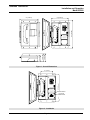
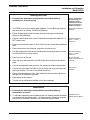
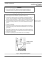
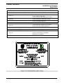
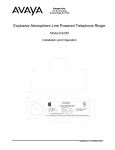
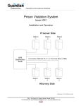
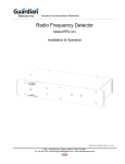
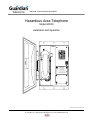
Industrial Communications Worldwide
Hazardous Area Telephone
Model EP600
Installation and Operation
SN#W
GUARDIAN TELECOM INC.
EP600 TELEPHONE
TELEPHONE FOR USE IN
R
HAZARDOUS LOCATIONS
LISTED
CLASS I, DIVISION 2, GROUPS A, B, C, & D
13X8
CLASS II, DIVISION 2, GROUPS F & G
CLASS II, DIVISION 1, GROUPS E, F, & G (CSA only)
CSA ENCLOSURE TYPE 3R
DOC & FCC APPROVED
L.N. 21
CAT. NO. STYLE 12
R.E.N 0.4A
SEE USER GUIDE FOR INSTALLATION
LR65547
MADE IN CANADA
CAUTION:
KEEP COVER TIGHT WHILE CIRCUITS ARE ALIVE.
FIELD REPAIR NOT POSSIBLE.
ATTENTION: GARDER LE COUVERCLE BIEN FERME TANT QUE
QUE CIRCUITS SONT SOUS TENSION. CET APPAREIL
NE PEUT ETRE REPARE A PIED D'OEUVRE.
P000115 Rev. E 11/23/2004 10:00
7552 - 10th Street N.E. Calgary, Alberta, Canada T2E 8W1
Ph: 403.258.3100 \ email:[email protected] \ www.guardiantelecom.com
Guardian Telecom Inc.
Installation and Operation
Model EP600
Table of Contents
Package Contents ......................................................................................................2
Overview ....................................................................................................................3
Features .....................................................................................................................3
Installing the EP600 ...................................................................................................5
Maintenance...............................................................................................................5
Operation ...................................................................................................................6
Setting Tone/Pulse Operation ....................................................................................6
Engineering Specifications .........................................................................................7
Warranty.....................................................................................................................9
Disclaimer ..................................................................................................................9
Warning ......................................................................................................................9
Service Telephone Number........................................................................................9
Feedback ...................................................................................................................9
Guardian Product Return .........................................................................................10
Table of Figures
Figure 1 - Overall Dimensions....................................................................................4
Figure 2 - Installation..................................................................................................4
Figure 3 - Setting Tone/Pulse Operation....................................................................6
Package Contents
(1) EP600 Telephone
(1) Installation & Operation Manual
Page 2
Guardian Telecom Inc.
Installation and Operation
Model EP600
Overview
Hazardous Area Telephone
The EP600 Telephone is designed to provide safe, reliable communication in Class 1, Division 2,
hazardous locations. The unit is housed in a rugged, weather and corrosion resistant enclosure that
ensures operation in severe conditions.
Features
Enclosure
• weather tight, rugged Valox & steel
•
spring loaded hinged door
•
stainless steel mounting bracket
Keypad
• standard 3 x 4 matrix
Magnetic Reed Hook Switch
• no moving parts
Surge Arrestor
• prevents damage to the electronic circuitry in the event of a high
voltage spike on the telephone line
Wall Mount
• easily mounted on any sturdy vertical structure
Noise Reducing Microphone
• allows a high level of intelligibility in locations with high background
noise
Tone (DTMF) Operation
• factory set to tone (DTMF) dialing
•
can be ordered set for pulse dialing or configured in the field
Heavy Duty Handset Cord
• withstands severe use
Hearing-Aid Compatible
• compatible with inductively coupled hearing-aid devices
Page 3
Guardian Telecom Inc.
Installation and Operation
Model EP600
8.8" [224mm]
9.7" [246mm]
EP600 TELEPHONE
MADE IN CANADA
CAUTION:
3.9" [99mm]
3.8" [97mm]
2.9" [74mm]
KEEP COVER TIGHT WHILE CIRCUITS ARE ALIVE.
FIELD REPAIR NOT POSSIBLE.
ATTENTION: GARDER LE COUVERCLE BIEN FERME TANT QUE
QUE CIRCUITS SONT SOUS TENSION. CET APPAREIL
NE PEUT ETRE REPARE A PIED D'OEUVRE.
Figure 1 - Overall Dimensions
6.0" [152mm]
GUARDIAN TELECOM INC.
EP600 TELEPHONE
LR65547
TELEPHONE FOR USE IN
R
HAZARDOUS LOCATIONS
LISTED
CLASS I, DIVISION 2, GROUPS A, B, C, & D
13X8
CLASS II, DIVISION 2, GROUPS F & G
CLASS II, DIVISION 1, GROUPS E, F, & G (CSA only)
CSA ENCLOSURE TYPE 3R
DOC & FCC APPROVED
CAT. NO. STYLE 12
R.E.N 0.4A
SEE USER GUIDE FOR INSTALLATION
L.N. 21
13.0" [330mm]
SN#W
MADE IN CANADA
CAUTION:
KEEP COVER TIGHT WHILE CIRCUITS ARE ALIVE.
FIELD REPAIR NOT POSSIBLE.
ATTENTION: GARDER LE COUVERCLE BIEN FERME TANT QUE
QUE CIRCUITS SONT SOUS TENSION. CET APPAREIL
NE PEUT ETRE REPARE A PIED D'OEUVRE.
Figure 2 - Installation
Page 4
GROUND GREEN
TIP & RING
CONNECTIONS
14.0" [356mm]
GUARDIAN TELECOM INC.
TELEPHONE FOR USE IN
R
HAZARDOUS LOCATIONS
LISTED
CLASS I, DIVISION 2, GROUPS A, B, C, & D
13X8
CLASS II, DIVISION 2, GROUPS F & G
CLASS II, DIVISION 1, GROUPS E, F, & G (CSA only)
CSA ENCLOSURE TYPE 3R
DOC & FCC APPROVED
L.N. 21
CAT. NO. STYLE 12
R.E.N 0.4A
SEE USER GUIDE FOR INSTALLATION
LR65547
11.8" [300mm]
12.0" [305mm]
SN#W
Guardian Telecom Inc.
Installation and Operation
Model EP600
Installing the EP600
•
Declassify the hazardous location before proceeding with any
installation or electrical wiring.
Caution: Installation or
electrical wiring in a
hazardous location
could result in serious
injury to personnel or
damage to property.
•
The EP600 is set to tone dialing when shipped. If pulse dialing is required
see the section on Setting Tone/Pulse Operation.
See: Setting Tone/Pulse
Operation
•
Follow all appropriate electrical codes and use only approved electrical
fittings for the installation.
•
Choose a wall location that is free of obstructions and permits space for ½”
NPT conduit runs.
•
Ensure mounting can support 5 lbs (2.3 kgs) and any foreseeable additional
load.
•
Ensure that none of the electrical connection circuits are live.
•
Use the template provided or the stainless steel mounting bracket to locate
and drill holes for mounting screws.
See: EP600 Drawing,
Figure 1 - Overall
Dimensions.
•
Secure the unit to the wall.
•
Open the door and remove the four #8 Philips drive screws on the access
plate.
Tip: Use #8 or M4
screws to secure the unit
to the wall.
•
Connect an approved earth ground to the center post of the surge arrestor.
•
Connect the wires from the PABX or CO to the tip and ring connections on
the surge arrestor. (The unit is not polarity sensitive.)
•
Ensure all connections are tight, then replace the access plate and secure
with the four #8 Philips drive screws.
•
Apply power to the system.
•
Test the unit by calling from another unit on the exchange.
See: EP600 Drawing,
Figure 1 - Overall
Dimensions.
See: Figure 2 Installation
Maintenance
•
Declassify the hazardous location before proceeding with any
maintenance or repairs.
•
To maintain hazardous area compliance the only field adjustment permitted
is to change the tone/pulse setting. All other repairs or alterations must be
carried out by Guardian Telecom or an Authorized Service Depot.
Page 5
See: Warranty and
Guardian Product Return
Guardian Telecom Inc.
Installation and Operation
Model EP600
Operation
•
Once your Model EP600 Telephone has been properly installed and
energized, operation is identical to most other single line telephones.
Setting Tone/Pulse Operation
Ensure that none of the electrical connection circuits are live.
•
Loosen the five captive screws in the faceplate and swing the faceplate to
the left. If the set is installed on a vertical surface the faceplate will stay
open like a book in this position. Take care not to disturb the internal wiring.
•
Set the Tone/Pulse jumper for the desired operation. For pulse, set jumper
between the center pin and the “P”, for tone set it between the center pin
and “T”.
•
Replace the faceplate.
•
Check the set visually for loose screws and trapped wires. Check that the
handset hangs freely in the cradle and that the handset cord is not trapped
by the door.
•
Check that the faceplate is snug to its gasket, paying particular attention to
the area around the cradle. Check that the door closes flush to the housing.
•
Apply power to the system.
•
Test the unit by calling to and from another unit on the exchange.
RINGER
•
HS
TONE PULSE
JUMPER
HK
P
T
TIP SPARE RING SPARE
Figure 3 - Setting Tone/Pulse Operation
Page 6
See: Figure 3 - Setting
Tone/Pulse Operation
Guardian Telecom Inc.
Installation and Operation
Model EP600
Engineering Specifications
Electrical Performance
AUDIBLE RANGE FREQUENCY RESPONSE
300 - 3400 HZ
DIALING METHOD
DTMF TONE or 40/60 PULSE AT 10 PPS
TRANSMIT OBJECTIVE LOUDNESS RATING (TOLR)
-40 +/- 3 dB
RECEIVE OBJECTIVE LOUDNESS RATING (ROLR)
47 +/- 3 dB
SIDE TONE OBJECTIVE LOUDNESS RATING (SOLR)
10 +/- 4 dB
RINGER OUTPUT
75 dB Maximum
FCC RINGER EQUIVALENCE NUMBER (REN)
0.7 B (mechanical bell)
SET IMPEDANCE
600 OHMS NOMINAL
MAXIMUM LOOP
15 KFt (4.6 KM)
Electrical Requirements
RINGER SENSITIVITY
40 - 100 V, 16 - 25 HZ
LINE VOLTAGE
24 - 56 VDC
LOOP CURRENT
20 - 120 MA
CONNECTION METHOD
SURGE ARRESTOR
Environmental
WEATHER AND CORROSION RESISTANT
ENCLOSURE 3R
TEMPERATURE
-40O TO +60O C (-40O TO +140O F)
HUMIDITY
0 TO 95% RH
DUST RESISTANT
CLASS II HAZARDOUS LOCATIONS
Mechanical
HOOK SWITCH (CRADLE SWITCH) LIFE
>1 000 000 OPERATIONS
BODY CONSTRUCTION
FACEPLATE
GE VALOX 357 ENGINEERING POLYMER
STAINLESS STEEL
DIMENSIONS (H x W x D)
14 X 9.7 X 3.9 INCHES (356 X 246 x 99 MM)
NET WEIGHT
5 LBS (2.3 KG)
HANDSET MATERIAL
HIGH IMPACT ABS
MICROPHONE
NOISE REDUCING ELECTRET
OPTIONAL MICROPHONE
NOISE CANCELING DYNAMIC
RECEIVER
HEARING AID COMPATIBLE
STANDARD MOUNTING
VERTICAL WALL
CONNECTION FITTINGS
1/2” NPT CONDUIT HUB
HARDWARE MATERIAL
STAINLESS STEEL
R
Page 7
Guardian Telecom Inc.
Installation and Operation
Model EP600
Compliance
CANADIAN STANDARDS ASSOCIATION (CSA)
REFERENCE NUMBER: LR65547-23
STYLE 12
CLASS I, DIVISION 2, GROUPS A, B, C AND D
CLASS I, ZONE 2, GROUP IIC
CLASS II, DIVISION 1 & 2, GROUPS E, F AND G
STYLE 21
CLASS II, DIVISION 1, GROUPS E, F AND G
STYLE 22
CLASS II, DIVISION 2, GROUP G
UNDERWRITERS LABORATORIES (UL)
LISTED 13X8 & E117495
STYLE 12
CLASS I, DIVISION 2, GROUPS A, B, C AND D
CLASS II, DIVISION 2, GROUPS F AND G
STYLE 22
CLASS II, DIVISION 2, GROUPS F & G
CONFORMITÉ EUROPÉENNE (CE)
STYLE 12
ENCLOSURE
EMC DIRECTIVE 89/336/EEC
LOW-VOLTAGE DIRECTIVE 73/23/EEC
ATEX DIRECTIVE 94/9/EC
CSA 3R
Figure 4 - I.D. and Compliance, (Style 12 only)
Page 8
Guardian Telecom Inc.
Installation and Operation
Model EP600
Warranty
Guardian Telecom warrants your product to be free of defects in material and workmanship for a period
of one year. Guardian Telecom will repair or replace any defective unit that is under warranty
This warranty is null and void if any non-authorized modifications have been made to this product, or if
it has been subjected to misuse, neglect, or accident. This warranty covers bench repairs only; such
repairs must be made at Guardian Telecom or an authorized service depot. Guardian Telecom is not
responsible for costs incurred for on-site service calls, freight, or brokerage.
A return authorization must be obtained prior to warranty claims or repairs.
Disclaimer
The products covered by this manual are designed for use in Industrial Environments and/or Hazardous
Locations. Due to the range of possible applications for these instruments the manufacturer will not be
responsible for damages or losses of any kind suffered as a result of the use of this product, including
consequential damages.
Warning
For the purposes of installing the product and replacing fuses this device may be opened and
reassembled by qualified personnel, following the instructions in the product manual. In the cases of
explosion proof and hazardous area devices it is imperative that mating surfaces be clean and
undamaged prior to reassembly and that fasteners be made up to the specified torque.
High voltages may be present in this device when connected to telephone wiring
Service Telephone Number
1-800-363-8010
Guardian Telecom provides a customer service telephone number which is toll-free within North
America. If you need assistance when installing or operating this product, please call the toll-free
telephone number between regular business hours (8:00AM-5:00PM), Mountain Standard Time. If you
are calling outside of regular business hours, please leave a detailed message, and a member of
Guardian Telecom’s Service Department will return your call as soon as possible. If your product
requires service, Guardian personnel will supply you with an RMA (return materials authorization)
number over the telephone or through our web site product return page. This number must be included
with your return address and the name of the person to contact.
Guardian Telecom Inc.
7552 - 10th Street N.E.
Calgary, Alberta, Canada T2E 8W1
Toll-free 1-800-363-8010
Ph. (403) 258-3100
Fax. (403) 253-4967
www.guardiantelecom.com
Feedback
Guardian Telecom continually strives to make reliable, durable, and easy to use products. If you, as an
installer or user of our equipment, have any suggestions for improvements to this or any of our products
or documents, including this manual, we would appreciate hearing from you.
Page 9
Guardian Telecom Inc.
Installation and Operation
Model EP600
Guardian Product Return
Guardian products have been quality tested and are in full working order when
shipped from the factory, given the rugged nature of these products, shipping is not
expected to damage a unit. In the unlikely event of a malfunction, Guardian follows the
three step procedure below.
Step I - On-Site Correction
•
The most common source of difficulties with a new product is improper installation
in one of two ways: incorrect wiring connections or connection to an incorrect
power source.
•
Product wiring needs to be properly connected to the on-site wiring. Correct wiring
instructions are shown in the user manual included with the product.
•
Connecting a telephone to a standard power source, rather than tip & ring, will
blow the telephone’s internal, user-replaceable fuse. In the event of fuse burn-out,
disconnect the telephone from the power source, replace the fuse, and reconnect
following the wiring diagrams provided with the product.
Step II - Return Materials Authorization (RMA)
•
When a product has been installed following user manual instructions, and the unit
fails to operate, the user must contact Guardian Telecom to obtain authorization to
return the product. This can be done by done by completing a RMA form online at
www.guardiantelecom.com, or by calling the service telephone number given in
this manual.
•
After providing information on the product, the owner and the nature of the
problem, Guardian will issue a RMA number, to be shown on documentation
returned with the product.
•
In addition to the RMA number, shipping documents should include name, address
and telephone number of the owner along with contact information for the person
responsible for the repair and/or the user who identified the malfunction.
•
(Where a product is being returned for repair from outside of Canada, customs
documentation must show the product’s serial number, date of export [date of
purchase], and a notation that the equipment is: “Canadian goods returning.”)
Step III - Factory Authorized Service
•
Once received, each product is carefully inspected and tested. If the product is
under warranty, repairs are completed and the product returned to the owner,
generally within five working days of receipt by the factory.
•
A product that has been subjected to misuse, neglect or accident or is beyond the
warranty period will be evaluated. The service department will provide the owner’s
representative with a repair cost estimate. Once approved, repairs are completed
and the product returned, generally within five working days.
Page 10
Guardian Telecom Inc.
Installation and Operation
Model EP600
Notes:
Model No.
Part No.
Serial No.
Date of Purchase
Page 11
Guardian Telecom Inc.
7552 - 10th Street N.E.
Calgary, Alberta, Canada T2E 8W1
Toll-free 1-800-363-8010
Ph. (403) 258-3100
Fax. (403) 253-4967
www.guardiantelecom.com
E-mail: [email protected]
Industrial Communications Worldwide
© Guardian Telecom Inc. 2004