1
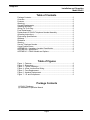
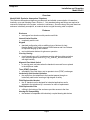
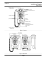
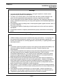
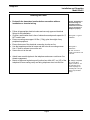
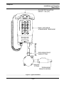
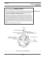
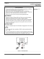
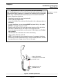
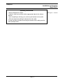
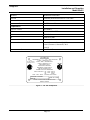
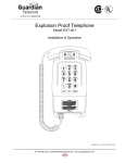
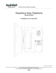
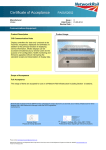
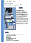
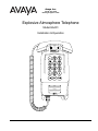
Avaya Inc.
211 Mt. Airy Road
Basking Ridge NJ 07920
Explosive Atmosphere Telephone
Model EA401
Installation & Operation
AVAYA
TELEPHONE FOR USE IN HAZARDOUS LOCATIONS
[Exia]
Associated equipment
Appareillage Connexe
LR65547
CLASS I GROUPS B, C, & D
CLASS I ZONE 1, GROUPS IIB+H2
CLASS II GROUPS E, F, & G
ENCLOSURE TYPE 4
RECEPTACLE PROVIDES
INTRINSICALLY SAFE OUTPUT
USE ONLY MODEL EA10H
HANDSET WITH THIS TELEPHONE
LISTED
13X8
RELAY CONTACTS
10A 1/3HP 240V AC
10A 1/3HP 120V AC
10A
30V DC
FUSE: 0.25A 48VDC - TYPE 2AG, FAST-ACTING
COMCODE: 700302045
SER. NO.
MOD. NO.: EA401
REFER TO USER GUIDE FOR INSTALLATION
MADE IN CANADA
WARNING
FIELD REPAIR NOT POSSIBLE. FOR SERVICE RETURN TO FACTORY. TO PREVENT
IGNITION OF HAZARDOUS ATMOSPHERE, DISCONNECT FROM THE SUPPLY CIRCUIT
BEFORE OPENING OR REPLACING FUSE. KEEP TIGHTLY CLOSED WHEN CIRCUITS
ARE ALIVE. ALL CONDUIT RUNS MUST BE SEALED WITHIN 18 INCHES (450 mm) OF
THIS ENCLOSURE. BREAKING OF REAR BOLT SEALS VOIDS MANUFACTURER'S
WARRANTY. SUBSTITUTION OF COMPONENTS MAY IMPAIR INTRINSIC SAFETY.
ATTENTION
CET APPAREIL NE PEUT ETRE REPARE A PIED D'OEUVRE. NE PAS L'OUVRIR.
LES BOULONS DOIVENT ETRE BIEN SERRES DEBRANCHE LE TELEPHONE
AVANT LE REMPLACEMENT DU FUSIBLE. RETOURNER L'APPAREIL A L'USINE
POUR LE DEPANNAGE. LE FAIT DE BRISER LE SCEAU DU FABRICANT A
L'ARRIERE DE L'APPAREIL ANNUELE LA GUARANTIE DU FABRICANT.
Industry Canada
Industrie Canada
1012 4339 A
P005975 Rev. A 11/13/2003 5:24 PM
Avaya Inc.
Installation and Operation
Model EA401
Table of Contents
Package Contents.............................................................................................2
Overview ...........................................................................................................2
Features ............................................................................................................2
Warnings ...........................................................................................................2
General Requirements ......................................................................................2
Installing the EA401 ..........................................................................................2
Wiring For Tip & Ring........................................................................................2
Fuse Replacement ............................................................................................2
Replacement Of EA10H Telephone Handset Assembly...................................2
Operating Instructions .......................................................................................2
Engineering Specifications................................................................................2
Warranty............................................................................................................2
Disclaimer .........................................................................................................2
Warning.............................................................................................................2
Service Telephone Number ..............................................................................2
Avaya Product Return .......................................................................................2
APPENDIX A - Hazardous Location Classification ...........................................2
APPENDIX B - Applications ..............................................................................2
APPENDIX C - EA401 Models and Options .....................................................2
Table of Figures
Figure 1 - Features............................................................................................2
Figure 2 - Dimensions .......................................................................................2
Figure 3 - Typical Installation ............................................................................2
Figure 4 - Lower Junction Box Wiring ...............................................................2
Figure 5 - Fuse Replacement............................................................................2
Figure 6 - Handset Replacement ......................................................................2
Figure 7 - I.D. and Compliance .........................................................................2
Package Contents
(1) EA401 Telephone
(1) Installation & Operation Manual
Page 2
Avaya Inc.
Installation and Operation
Model EA401
Overview
Model EA401 Explosive Atmosphere Telephone
This Explosive Atmosphere telephone provides safe and reliable communication in hazardous
locations, up to and including Class I Division 1. Only standard wiring and fittings are required to
connect the telephone to the system; no barrier is necessary. Since the heavy duty cast aluminum
enclosure is basically soundproof, an external device to signal incoming calls is required.
Features
Enclosure
• cast copper free aluminum with powder coat finish
Internal Sealed Cavities
• completely seal the unit
Keypad
• standard configuration with an additional row of buttons for Last
Number Redial, Link/Flash to access PABX features and Line Release
to duplicate hanging up the handset
• one inch diameter buttons for gloves-on operation
Circuitry Coating
• circuit boards have a UV cured epoxy coating which provides protection
from corrosive agents such as H2S, SO2, and NH3, and environments
with high humidity
Magnetic Reed Hook Switch
• no moving parts, activates when the handset is removed from or placed
in the telephone cradle
Tone (DTMF) Operation
• selectable in the field; factory set to operate to tone (DTMF) exchanges
Intrinsically Safe Handset Operation
• the output from the telephone to the handset passes through an
intrinsically safe barrier ensuring a high degree of safety
Field Replaceable Handset
• the 10’ handset cord is designed for industrial applications and is
attached to the telephone by a connector for ease of replacement
Field Replaceable Fuse
• a fitting in the bottom of the enclosure provides access to the fuse
Hearing-Aid Compatibility
• the handset is compatible with inductively coupled hearing-aid devices
Page 3
Avaya Inc.
Installation and Operation
Model EA401
MAGNETIC REED
HOOK SWITCH
INTRINSICALLY SAFE
HANDSET
AVAYA
TELEPHONE FOR USE IN HAZARDOUS LOCATIONS
CLASS I GROUPS B, C, & D
CLASS I ZONE 1, GROUPS IIB+H2
CLASS II GROUPS E, F, & G
ENCLOSURE TYPE 4
[Exia]
Associated equipment
Appareillage Connexe
RECEPTACLE PROVIDES
INTRINSICALLY SAFE OUTPUT
USE ONLY MODEL EA10H
HANDSET WITH THIS TELEPHONE
LR65547
LISTED
13X8
RELAY CONTACTS 10A 1/3HP 240V AC
10A 1/3HP 120V AC
10A
30V DC
FUSE: 0.25A 48VDC - TYPE 2AG, FAST-ACTING
COMCODE: 700302045
SER. NO.
PRODUCTION IDENTIFICATION
LABEL
MOD. NO.: EA401
REFER TO USER GUIDE FOR INSTALLATION
MADE IN CANADA
HANDSET CORD
KEYPAD
LINK
(PBX TRANSFER)
REDIAL
RELEASE
WARNING
FIELD REPAIR NOT POSSIBLE. FOR SERVICE RETURN TO FACTORY. TO PREVENT
IGNITION OF HAZARDOUS ATMOSPHERE, DISCONNECT FROM THE SUPPLY CIRCUIT
BEFORE OPENING OR REPLACING FUSE. KEEP TIGHTLY CLOSED WHEN CIRCUITS
ARE ALIVE. ALL CONDUIT RUNS MUST BE SEALED WITHIN 18 INCHES (450 mm) OF
THIS ENCLOSURE. BREAKING OF REAR BOLT SEALS VOIDS MANUFACTURER'S
WARRANTY. SUBSTITUTION OF COMPONENTS MAY IMPAIR INTRINSIC SAFETY.
WARNING LABEL
ATTENTION
CET APPAREIL NE PEUT ETRE REPARE A PIED D'OEUVRE. NE PAS L'OUVRIR.
LES BOULONS DOIVENT ETRE BIEN SERRES DEBRANCHE LE TELEPHONE
AVANT LE REMPLACEMENT DU FUSIBLE. RETOURNER L'APPAREIL A L'USINE
POUR LE DEPANNAGE. LE FAIT DE BRISER LE SCEAU DU FABRICANT A
L'ARRIERE DE L'APPAREIL ANNUELE LA GUARANTIE DU FABRICANT.
Industry Canada
Industrie Canada
1012 4339 A
MOUNTING LUG
TIP/RING/GROUND WIRES
ENTRY POINT
FUSE
HANDSET CORD
CONNECTOR
Figure 1 - Features
10.1" [257mm]
Ø0.4" [Ø10mm]
2 PLCS.
8.5" [216mm]
4.4" [111mm]
AVAYA
AVAYA
TELEPHONE FOR USE IN HAZARDOUS LOCATIONS
LR65547
CLASS I GROUPS B, C, & D
CLASS I ZONE 1, GROUPS IIB+H2
CLASS II GROUPS E, F, & G
ENCLOSURE TYPE 4
RECEPTACLE PROVIDES
INTRINSICALLY SAFE OUTPUT
USE ONLY MODEL 301SC OR 301SCPB
HANDSET WITH THIS TELEPHONE
TELEPHONE FOR USE IN HAZARDOUS LOCATIONS
[Exia]
Associate d equipment
Apparei llage Connexe
LISTED
LR65547
13X8
RELAY CONTACTS 10A 1/3HP 240V AC
10A 1/3HP 120V AC
10A
3 0V DC
FUSE: 0.25A 48VDC - TYPE 2AG, FAST-ACTING
SER . NO.
CLASS I GROUPS B, C, & D
CLASS I ZONE 1, GROUPS IIB+H2
CLASS II GROUPS E, F, & G
ENCLOSURE TYPE 4
RECEPTACLE PROVIDES
INTRINSICALLY SAFE OUTPUT
USE ONLY MODEL 301SC OR 301SCPB
HANDSET WITH THIS TELEPHONE
LISTED
13X8
RELAY CONTACTS
1 0A 1/3 HP 240V AC
1 0A 1/3 HP 120V AC
1 0A
30V DC
FUSE: 0.25A 48VDC - TYPE 2AG, FAST-ACTING
C AT. NO .: 401
SER. NO.
REFER TO USER GUIDE FOR INSTALLATION
M ADE IN CANADA
CAT. NO.: 401
11.4" [290mm]
13.5" [342mm]
REFER TO USER GUIDE FOR INSTALLATION
MADE IN CANADA
WARNING
12.8" [326mm]
[Exia]
Associate d eq uipment
Appa reillage Connexe
4.9" [124mm]
WARNING
FIELD REPAIR NOT POSSIBLE. FOR SERVICE RETURN TO FACTORY. TO PREVENT
FIELD REPAIR NOT POSSIBLE. FOR SERVICE RETURN TO FACTORY. TO PREVENT
IGNITION OF HAZARDOUS ATMOSPHERE, DISCONNECT FROM THE SUPPLY CIRCUIT
BEFORE OPENING OR REPLACING FUSE. KEEP TIGHTLY CLOSED WHEN CIRCUITS
ARE ALIVE. ALL CONDUIT RUNS MUST BE SEALED WITHIN 18 INCHES (450 mm) OF
THIS ENCLOSURE. BREAKING OF REAR BOLT SEALS VOIDS MANUFACTURER'S
WARRANTY. SUBSTITUTION OF COMPONENTS MAY IMPAIR INTRINSIC SAFETY.
ATTENTION
ATTENTION
CET APPAREIL NE PEUT ETRE REPARE A PIED D'OEUVRE. NE PAS L'OUVRIR.
CET APPAREIL NE PEUT ETRE REPARE A PIED D'OEUVRE. NE PAS L'OUVRIR.
LES BOULONS DOIVENT ETRE BIEN SERRES DEBRANCHE LE TELEPHONE
AVANT LE REMPLACEMENT DU FUSIBLE. RETOURNER L'APPAREIL A L'USINE
POUR LE DEPANNAGE. LE FAIT DE BRISER LE SCEAU DU FABRICANT A
L'ARRIERE DE L'APPAREIL ANNUELE LA GUARANTIE DU FABRICANT.
LES BOULONS DOIVENT ETRE BIEN SERRES DEBRANCHE LE TELEPHONE
AVANT LE REMPLACEMENT DU FUSIBLE. RETOURNER L'APPAREIL A L'USINE
POUR LE DEPANNAGE. LE FAIT DE BRISER LE SCEAU DU FABRICANT A
L'ARRIERE DE L'APPAREIL ANNUELE LA GUARANTIE DU FABRICANT.
Industry Canada
Industrie Canada
Industry Canada
Industrie Canada
1012 4339 A
1012 4339 A
Ø0.3" [Ø9mm]
4.6" [117mm]
Figure 2 - Dimensions
Page 4
2 PLCS.
Avaya Inc.
Installation and Operation
Model EA401
Warnings
•
•
•
•
•
•
In no case should this telephone apparatus or wiring be installed in a location where
acetylene may be present in the atmosphere.
Two back cover retaining bolts on the model EA401 are factory sealed. Damage to the
seals voids the warranty and safety approvals, and may compromise unit safety.
It is the responsibility of the installer to advise a supervisor if any telephone equipment or
wiring in a hazardous location may not comply with regulations and standards applicable to
that location.
Avoid creating a spark by striking tools or metal objects together, against concrete, stone, or
any similar substance.
Test equipment capable of producing an electric spark must not be used in an explosive
atmosphere.
All apparatus should be completely assembled and properly sealed before reconnecting
power.
General Requirements
•
A EA401 telephone should only be installed with proper authorization. It is necessary for
the customer and the telephone company to have a definite agreement regarding the
location of the telephone unit, auxiliary apparatus, and protector (i.e. lightning arrestor at the
demarcation block).
NOTE:
• To maintain maximum protection, broken or worn parts must be replaced immediately. Any
abnormal conditions should be immediately corrected. Periodic inspections are
recommended.
• Unless otherwise specified, the customer must provide and install explosion-proof conduit
and fittings approved by the Canadian Standards Association (CSA) or listed by
Underwriters Laboratories (UL). The customer is also responsible for having the system
inspected and approved by the appropriate electrical inspector in accordance with local
legal requirements and National Electrical Code Standards.
• EA401 telephone sets and associated external bells and control relays are designed to
provide security against ignition of the surrounding atmosphere. All parts of the apparatus
which might produce an electrical spark are completely enclosed. All passages to the
outside are made such that any spark or flame will be cooled to a temperature below the
ignition threshold before reaching the outside atmosphere.
• If the handset or cord is damaged, it must be replaced with part EA10H handset assembly.
Handsets and cords are not covered under warranty other than to be free of defects at time
of installation.
• If the telephone is found to be defective or in need of repair, it must be returned to the
manufacturer. No field repair is possible other than replacement of the handset and fuse.
• Telephones in good condition may be moved from one location to another.
Page 5
Avaya Inc.
Installation and Operation
Model EA401
Installing the EA401
•
Declassify the hazardous location before proceeding with any
installation or electrical wiring.
•
Follow all appropriate electrical codes and use only approved electrical
fittings for the installation.
Choose a wall location that is free of obstructions and permits space for ½”
NPT conduit runs
Ensure mounting can support 16.5lbs. (7.5kg), plus the weight of any
peripheral equipment.
Ensure that none of the electrical connection circuits are live.
Use the template provided to locate and drill holes for mounting screws.
Use ¼” bolts or screws to mount the unit.
Secure the unit to the wall:
•
•
•
•
•
•
•
Attach lower conduit nipples to the telephone and ensure a minimum five
thread engagement.
Mount an approved explosion proof junction box within 45.7 cm (18") of the
telephone’s lower sealing cavity and bring telephone wires into this box.
Page 6
Caution: Installation or
electrical wiring in a
hazardous location
could result in serious
injury to personnel or
damage to property.
See: Figure 3 - Typical
Installation.
See: Figure 2 Dimensions.
Tip: Use ¼” bolts or
screws to secure the unit
to the wall.
Tip: Fittings compatible
with 1/2 inch NPT
nipples, conduit, or 1/2
inch explosion-proof
flexible couplings not
exceeding 45.7 mm (18
inches) may be fitted
directly.
Avaya Inc.
Installation and Operation
Model EA401
SUGGESTED MOUNTING
HEIGHT: 1.4m (4.6')
AVAYA
TELEPHONE FOR USE IN HAZARDOUS LOCATIONS
[Exia]
Associated equipment
Appareillage Connexe
LR65547
CLASS I GROUPS B, C, & D
CLASS I ZONE 1, GROUPS IIB+H2
CLASS II GROUPS E, F, & G
ENCLOSURE TYPE 4
RECEPTACLE PROVIDES
INTRINSICALLY SAFE OUTPUT
USE ONLY MODEL EA10H
HANDSET WITH THIS TELEPHONE
LISTED
13X8
RELAY CONTACTS 10A 1/3HP 240V AC
10A 1/3HP 120V AC
10A
30V DC
FUSE: 0.25A 48VDC - TYPE 2AG, FAST-ACTING
COMCODE: 700302045
SER. NO.
MOD. NO.: EA401
REFER TO USER GUIDE FOR INSTALLATION
MADE IN CANADA
EA401: EXPLOSIVE
ATMOSPHERE TELEPHONE
WARNING
FIELD REPAIR NOT POSSIBLE. FOR SERVICE RETURN TO FACTORY. TO PREVENT
IGNITION OF HAZARDOUS ATMOSPHERE, DISCONNECT FROM THE SUPPLY CIRCUIT
BEFORE OPENING OR REPLACING FUSE. KEEP TIGHTLY CLOSED WHEN CIRCUITS
ARE ALIVE. ALL CONDUIT RUNS MUST BE SEALED WITHIN 18 INCHES (450 mm) OF
THIS ENCLOSURE. BREAKING OF REAR BOLT SEALS VOIDS MANUFACTURER'S
WARRANTY. SUBSTITUTION OF COMPONENTS MAY IMPAIR INTRINSIC SAFETY.
ATTENTION
CET APPAREIL NE PEUT ETRE REPARE A PIED D'OEUVRE. NE PAS L'OUVRIR.
LES BOULONS DOIVENT ETRE BIEN SERRES DEBRANCHE LE TELEPHONE
AVANT LE REMPLACEMENT DU FUSIBLE. RETOURNER L'APPAREIL A L'USINE
POUR LE DEPANNAGE. LE FAIT DE BRISER LE SCEAU DU FABRICANT A
L'ARRIERE DE L'APPAREIL ANNUELE LA GUARANTIE DU FABRICANT.
Industry Canada
Industrie Canada
18.0" [457mm] MAX.
1012 4339 A
EXPLOSION PROOF
UNION FITTING
SEALING
FITTING
TIP/RING/GND
FROM CO OR PBX
Figure 3 - Typical Installation
Page 7
Avaya Inc.
Installation and Operation
Model EA401
Wiring For Tip & Ring
•
•
•
•
•
After mounting the telephone follow these steps.
Run tip, ring and ground wires from the local exchange into the lower junction
box. The tip and ring wires must not be connected to the local exchange until
installation is completed. A sealing fitting must be installed within 45.7 cm
(18") on the exchange side of the lower junction box.
Attach the tip and ring wires to the orange and blue wires from telephone
using twist on wire connectors. Attach #10 ring lugs to the end of the three
green wires and attach these wires to the ground screw in the junction box.
For tone (DTMF) dialing operation of the telephone, connect the two brown
wires together and protect the connection with a twist-on wire connector. For
pulse dialing operation of the telephone, separate the two brown wires and
insulate the ends to prevent accidental contact with the interior of the junction
box.
Check the wiring and close the junction box.
See: Figure 4 - Lower
Junction Box Wiring
TO EA401
GROUND (GREEN)
TIP & RING
(BLUE & ORANGE)
NOT POLARITY SENSITIVE
TONE/PULSE SWITCH
(BROWN)
TONE/PULSE: CONNECT
WIRES AND KEEP WIRES
ISOLATED
FROM EXCHANGE
TIP
RING
GROUND
Figure 4 - Lower Junction Box Wiring
Page 8
Avaya Inc.
Installation and Operation
Model EA401
Fuse Replacement
•
•
•
•
Disconnect the telephone from tip and ring power supplied by the PABX or
central office before attempting to replace the fuse.
Remove the 1/2” NPT close up plug (item A) with a 1/4” Allen key.
Remove fuse holder cap (item B) with a flat blade screwdriver. Rotate fuse
holder cap 1/4 turn counterclockwise (to the left) to remove.
Remove fuse (item C) from the cap and insert replacement fuse.
WARNING!
•
•
•
Replace only with a 0.25 amp 2AG fuse. Failure to do so will void safety
approval and warranties and may create an explosion hazard.
With fuse mounted in the cap, re-install in the fuse holder with a flat blade
screwdriver and rotate 1/4 turn clockwise (to the right) to lock in position.
Screw the 1/2” NPT close-up plug into housing with a minimum of five full
threads of engagement.
ATTENTION!
•
CSA & UL standards require five full threads of engagement for the close-up
plug.
NOTES
•
•
A field replaceable fuse is available on EA401 models manufactured after
Jan. 1, 1997.
If, on reconnecting power, the fuse fails, check the telephone system wiring.
The fuse protects the tip and ring line from the telephone system. It is usually
powered at 48 volts DC and should not be connected to 120 volts AC.
WARNING
FIELD REPAIR NOT POSSIBLE. FOR SERVICE RETURN TO FACTORY. TO PREVENT
IGNITION OF HAZARDOUS ATMOSPHERE, DISCONNECT FROM THE SUPPLY CIRCUIT
BEFORE OPENING OR REPLACING FUSE. KEEP TIGHTLY CLOSED WHEN CIRCUITS
ARE ALIVE. ALL CONDUIT RUNS MUST BE SEALED WITHIN 18 INCHES (450 mm) OF
THIS ENCLOSURE. BREAKING OF REAR BOLT SEALS VOIDS MANUFACTURER'S
WARRANTY. SUBSTITUTION OF COMPONENTS MAY IMPAIR INTRINSIC SAFETY.
ATTENTION
CET APPAREIL NE PEUT ETRE REPARE A PIED D'OEUVRE. NE PAS L'OUVRIR.
LES BOULONS DOIVENT ETRE BIEN SERRES DEBRANCHE LE TELEPHONE
AVANT LE REMPLACEMENT DU FUSIBLE. RETOURNER L'APPAREIL A L'USINE
POUR LE DEPANNAGE. LE FAIT DE BRISER LE SCEAU DU FABRICANT A
L'ARRIERE DE L'APPAREIL ANNUELE LA GUARANTIE DU FABRICANT.
Industry Canada
Industrie Canada
1012 4339 A
C
B
A
Figure 5 - Fuse Replacement
Page 9
See: Figure 5 - Fuse
Replacement
Avaya Inc.
Installation and Operation
Model EA401
Replacement Of EA10H Telephone Handset Assembly
Note: The handset cord is a 3.0 m (10 ft) long coiled cable designed specifically
for use with the EA401 telephone. If damaged, the assembly may be replaced in
the field. Only an EA10H handset assembly may be connected to the EA401
Explosive Atmosphere telephone.
• Completely unscrew the upper knurled collar.
• Pull the old plug straight down.
• Inspect the inside of the socket and the threads for dirt or damage; clean as
necessary.
• For safe installation, the new handset MUST be placed firmly in the cradle
PRIOR to engaging the plug in socket.
• Bring the new plug up to the socket and rotate the plug until the slot in the
shell lines up with the key in the socket. Insert plug into socket.
• Screw the upper knurled collar onto the socket. Hand tighten only, Do Not
use a wrench.
• Call back and forth to another set to check functionality.
• Hang up firmly between each call.
• NOTE: If the handset is being replaced because of an apparent telephone
malfunction, and the replacement fails to restore normal operations, contact
the manufacturer to arrange return of the unit for repair.
EA401: EXPLOSIVE
ATMOSPHERE TELEPHONE
HANDSET JACK
KNURLED COLLAR
HANDSET PLUG
Figure 6 - Handset Replacement
Page 10
See: Figure 6 - Handset
Replacement
Avaya Inc.
Installation and Operation
Model EA401
Operating Instructions
•
•
•
•
•
Remove handset from cradle.
Listen for a dial tone and then dial the appropriate digits for the feature
desired.
Upon completing a call hang up by returning the handset to the cradle.
Calls are answered by lifting the handset from the cradle.
To make another call without returning the handset to the cradle press the
RLS (release) button.
Page 11
See: Figure 1 - Features
Avaya Inc.
Installation and Operation
Model EA401
Engineering Specifications
Electrical Performance
AUDIBLE RANGE FREQUENCY RESPONSE
300 – 3400 HZ
DIALING METHOD
IEEE DTMF OR 40/60 PULSE, 10 PPS
TRANSMIT OBJECTIVE LOUDNESS RATING (TOLR)
-38 +/- 4 dB
RECEIVE OBJECTIVE LOUDNESS RATING (ROLR)
TYPICAL 52 +/- 4 dB
SIDE TONE OBJECTIVE LOUDNESS RATING (SOLR)
TYPICAL 20 +/- 3 DB
RINGER OUTPUT
N/A
FCC RINGER EQUIVALENCE
0.9 A, 1.9B
FLASH
600 MSEC TIMED DISCONNECT
REDIAL
13 DIGITS MAXIMUM
MAXIMUM LOOP
15 KFT (4,500 M) OF 22 AWG COPPER
Electrical Requirements
LINE VOLTAGE
24 – 56 VDC
LOOP CURRENT
20 - 120 MA
RINGER DETECT RELAY SENSITIVITY (OPTIONAL)
40 – 100 V, 16 – 25 HZ
CONNECTION METHOD
FACTORY SEALED WIRING THROUGH ½” CONDUIT ENTRY
FUSE
2AG 0.25 AMP 250 VOLT
Environmental
WEATHERPROOF & WATERTIGHT
ENCLOSURE NEMA 4
TEMPERATURE
-40O TO +60O C (-40O TO 140OF)
HUMIDITY
0 TO 95% RH NON CONDENSING
DUSTPROOF
¾” FLAT FLANGE DUSTPROOF JOINTS
Mechanical
HOOK SWITCH (CRADLE SWITCH) LIFE
>1 000 000 OPERATIONS
BODY CONSTRUCTION
COPPER FREE CAST ALUMINUM WITH POWDER COAT FINISH
DIMENSIONS
325 X 173 X 122 MM (12.8 X 6.8 X 4.8 INCHES)
NET WEIGHT
7.95 KG (17.5 LBS.)
HANDSET MATERIAL
HIGH IMPACT ABS
HANDSET CORD
3.0 M (10 FT) FIELD REPLACEABLE WITH LOW TEMPERATURE
POLYURETHANE JACKET
MICROPHONE
DYNAMIC
Page 12
Avaya Inc.
Installation and Operation
Model EA401
RECEIVER
HEARING AID COMPATIBLE
DIAL PAD
OVERSIZED ALUMINUM BUTTONS ON 1.125” GRID
STANDARD MOUNTING
VERTICAL WALL
CONNECTION FITTINGS
½” NPT CONDUIT ENTRY
Compliances
INDUSTRY CANADA
1012 4339 A
FCC
HQHCAN-65560-TE-E
CSA
LR65547-18
UL
13X8, & E117495
WEATHERPROOF & WATERTIGHT
ENCLOSURE NEMA 4
HAZARDOUS LOCATION APPROVALS
CLASS I, DIVISION 1. GROUPS B, C & D
CLASS II, DIVISION 1, GROUPS E, F & G
CLASS III
ENVIRONMENTAL SURVIVABILITY
MIL-STD-810E
TELEPHONE FOR USE IN HAZARDOUS LOCATIONS
CLASS I GROUPS B, C, & D
CLASS I ZONE 1, GROUPS IIB+H2
LISTED
CLASS II GROUPS E, F, & G
ENCLOSURE TYPE 4
RECEPTACLE PROVIDES
INTRINSICALLY SAFE OUTPUT
USE ONLY MODEL EA10H
LR65547
HANDSET WITH THIS TELEPHONE
13X8
[Exia]
Associated equipment
Appareillage Connexe
10A 1/3HP 240V AC
10A 1/3HP 120V AC
10A
30V DC
FUSE: 0.25A 48VDC - TYPE 2AG, FAST-ACTING
RELAY CONTACTS
COMCODE: 700302045
SER. NO.
MOD. NO.: EA401
REFER TO USER GUIDE FOR INSTALLATION
MADE IN CANADA
Figure 7 - I.D. and Compliance
Page 13
Avaya Inc.
Installation and Operation
Model EA401
Government Certification
Attached to the telephone are labels for Industry Canada and the United States Federal Communications Commission. These identify
equipment certifications indicating the 60 and 70 series telephones meet certain telecommunications network protective, operational
and safety requirements. These agencies do not guarantee the equipment will operate to the user's satisfaction.
Before installing this telephone equipment, users should ensure it is permissible to connect the equipment to facilities of the local
telecommunications company.
Equipment must be installed using acceptable connection methods. In some cases, the telephone users inside wiring, associated with
a single line service, may be extended by a certified connector assembly (telephone extension cord). The customer should be aware
that in some situations compliance with the above conditions may not prevent degradation of service.
Repairs to certified equipment should be made by a supplier designated authorized maintenance facility.
For their own protection users should ensure the electrical ground connections of the power utility, telephone lines and internal
metallic water pipe systems, if present, are connected. This precaution may be particularly important in rural areas.
CAUTION: Users should not attempt to make ground connections, but should contact the appropriate electrical inspection authority
or electrician.
Load Number (LN)
The Load Number (LN) assigned to each terminal device denotes the percentage of the total load to be connected to a telephone loop
used by the device. Termination on a loop may consist of any combination of devices subject only to the requirement that the total of
the Load Numbers of all the devices does not exceed 100.
Notification to Telephone Company
Upon request, the customer must notify the telephone company of the particular line to which the connection will be made and provide
the Industry Canada or FCC registration number. The local telephone company may request disconnection of the telephone where
alterations or malfunctions affect the telephone’s performance.
United States Federal Communications Commission
This equipment generates, uses and can radiate radio frequency energy, and if not installed and used in accordance with the
instruction manual, may cause interference to radio communications. It has been tested and found to comply with the limits for Class
A computing device pursuant to Subpart J of Part 15 of FCC rules, which are designed to provide reasonable protection against such
interference when operated in a commercial environment. Operation of this equipment in a residential area is likely to cause
interference in which case the user, at his own expense, will be required to take whatever measures may be required to correct the
interference.
Interference
There is no guarantee that interference will not occur in a particular installation. If interference to radio or television reception from this
equipment is suspected, proceed as follows:
1.
Unplug the set, check for the interference.
2.
Re-orient the receiving antenna.
3.
Relocate the set with respect to the receiver.
4.
Move the set away from the receiver.
If necessary, consult the supplier or an experienced radio/television technician for additional suggestions.
FCC Rules and Ringer Equivalence Number
This equipment complies with Part 68 of the FCC Rules. On the side of this equipment is a label that contains, among other
information, the FCC registration number and ringer equivalence number (REN) for this equipment. If requested, this information
must be provided to the telephone company.
The REN is used to determine the quantity of devices which may be connected to the telephone line. Excessive RENs on the
telephone line may result in the devices not ringing in response to an incoming call. In most, but not all areas, the sum of the RENs
should not exceed five. To be certain of the number of devices that may be connected to the line, as determined by the total RENs,
contact the telephone company to determine the maximum REN for the calling area.
Service changes and Limitations
The telephone company may make changes in its facilities, equipment, operations, or procedures that could affect the operation of the
equipment. If this happens, the telephone company will provide advance notice in order for you to make the necessary modifications
in order to maintain uninterrupted service.
This equipment can not be used on public coin telephone service as provided by your telephone company. Connection to party line
service is subject to state tariffs (contact the state public utility commission, public service commission or corporate commission for
information.)
Page 14
Avaya Inc.
Installation and Operation
Model EA401
Warranty
Avaya warrants your product to be free of defects in material and workmanship for a period of one year.
Avaya will repair or replace any defective unit that is under warranty free of charge.
This warranty is null and void if any non-authorized modifications have been made to this product, or if
it has been subjected to misuse, neglect, or accident. This warranty covers bench repairs only; such
repairs must be made at Avaya or an authorized service depot. Avaya is not responsible for costs
incurred for on-site service calls, freight, or brokerage.
A return authorization must be obtained prior to warranty claims or repairs.
Disclaimer
The products covered by this manual are designed for use in Industrial Environments and/or Hazardous
Locations. Due to the range of possible applications for these instruments the manufacturer will not be
responsible for damages or losses of any kind suffered as a result of the use of this product, including
consequential damages.
Warning
Avaya’s Model EA401 Explosive Atmosphere telephone must NOT be opened by the user, doing so
voids the warranty and safety approvals. The EA401 handset and fuse are externally accessible parts
which may be safely serviced by the user following procedures described in the manual.
Service Telephone Number
Avaya provides a customer service telephone number which is toll-free within North America. If you
need assistance when installing or operating this product, please call the toll-free telephone number
between regular business hours (8:00AM-5:00PM), Eastern Standard Time. If you are calling outside of
regular business hours, please leave a detailed message, and a member of Avaya’s Service
Department will return your call as soon as possible. If your product requires service, Avaya personnel
will supply you with an RMA (return materials authorization) number over the telephone or through our
web site product return page. This number must be included with your return address and the name of
the person to contact.
Avaya Inc.
211 Mt. Airy Road
Basking Ridge, NJ 07920
Toll-free: 1-866-GOAVAYA (1-866-462-8292)
Outside the US: +1-908-953-6000
www.avaya.com
Page 15
Avaya Inc.
Installation and Operation
Model EA401
Avaya Product Return
Avaya products have been quality tested and are in full working order when shipped from the factory, given the
rugged nature of these products, shipping is not expected to damage a unit. In the unlikely event of a
malfunction, Avaya follows the three step procedure below.
Step I - On-Site Correction
•
The most common source of difficulties with a new product is improper installation in one of two ways:
incorrect wiring connections or connection to an incorrect power source.
•
Product wiring needs to be properly connected to the on-site wiring. Correct wiring instructions are shown in
the user manual included with the product.
•
Connecting a telephone to a standard power source, rather than tip & ring, will blow the telephone’s internal,
user-replaceable fuse. In the event of fuse burn-out, disconnect the telephone from the power source,
replace the fuse, and reconnect following the wiring diagrams provided with the product.
Step II - Return Materials Authorization (RMA)
•
When a product has been installed following user manual instructions, and the unit fails to operate, the user
must contact Avaya to obtain authorization to return the product. This can be done by completing a RMA
form online at www.Avaya.com, or by calling the service telephone number given in this manual.
•
After providing information on the product, the owner and the nature of the problem, Avaya will issue a RMA
number, to be shown on documentation returned with the product.
•
In addition to the RMA number, shipping documents should include name, address and telephone number
of the owner along with contact information for the person responsible for the repair and/or the user who
identified the malfunction.
•
(Where a product is being returned for repair from outside of USA, customs documentation must show the
product’s serial number, date of export [date of purchase], and a notation that the equipment is: “USA goods
returning.”)
Step III - Factory Authorized Service
•
Once received, each product is carefully inspected and tested. If the product is under warranty, repairs are
completed and the product returned to the owner, generally within five working days of receipt by the
factory.
•
A product that has been subjected to misuse, neglect or accident or is beyond the warranty period will be
evaluated. The service department will provide the owner’s representative with a repair cost estimate. Once
approved, repairs are completed and the product returned, generally within five working days.
Page 16
Avaya Inc.
Installation and Operation
Model EA401
APPENDIX A - Hazardous Location Classification
CLASS I, DIVISION 1 & 2, GROUP B
acrolein
formaldehyde(gas)
butadiene
hydrogen
manufactured gases containing more than 30% hydrogen(by volume)
propyl nitrate
ethylene oxide
proplene oxide
CLASS I, DIVISION 1 & 2, GROUP C
acetaldehyde
epichlorohydrin
allyl alcohol
ethylene
butyl mercaptan
ethylenimine
n-butyraldehyde
ethyl mercaptan
carbon monoxide
n-ethyl morpholine
crotonaldehyde
hydrogen cyanide
dicyclopentadiene
hydrogen selenide
diethyl ether
hydrogen sulfide
diethylamine
isobutyraldehyde
di-isopropylamine
Isopropyl glycidyl ether
dimethylamine
methylacetylene
1,4-dioxane
methylacetylene-propadiene
di-n-propylamine
methyl ether
methyl formal
methyl mercaptan
monomethyl hydrazine
morpholine
nitroethane
nitromethane
2-nitropropane
propionaldehyde
n-propyl ether
tetrahydrofuran
triethylamine
unsymetrical dimethyl hydrazine
valeraldehyde
CLASS I, DIVISION 1 & 2, GROUP D
acetic acid
ethyl benzene
acetone
ethyl chloride
acetonitrile
ethylenediamine
acrylonitrile
ethylene dichloride
allyl chloride
ethyl glycol monomethyl ether
ammonia (3)
ethyl formate
n-amyl acetate
gasoline
sec-amyl acetate
heptane
benzene
heptene
butane
hexane
1-butanol (butyl alcohol)
2-hexanone
2-butanol (secondary butyl alcohol) hexenes
n-butyl acetate
isoamyl acetate
sec-butyl acetate
isoamyl alcohol
butylamine
isobutyl acrylate
butylene
isoprene
chlorobenzene
isopropyl acetate
chloroprene
isopropylamine
cyclohexane
isopropyl ether
cyclohexene
liquefied petroleum gas
cyclopropane
mesityl oxide
1,1-dichloroethane
methane
1,2-dichloroethylene
methanol
1,3-dichloropropene
methyl acetate
di-isobutylene
methyl acrylate
ethane
methylamine
ethanol
methylcyclohexane
ethyl acetate
methyl ethyl ketone
ethyl acrylate
methyl formate
ethylamine
methyl isobutyl ketone
methyl isocyanate
methyl methacrylate
2-methyl-1-propanol
2-methyl-2-propanol
naptha
nonane
nonene
octane
octene
pentane
1-pentanol
2-pentanone
1-pentene
petroleum naptha
propane
1-propanol
2-propanol
n-propyl acetate
propylene
propylene dichloride
propylene oxide
pyridine
styrene
toluene
tripropylamine
turpentine
vinyl acetate
vinyl chloride
vinylidene chloride
xylenes
Page 17
Avaya Inc.
Installation and Operation
Model EA401
APPENDIX A (cont.)
CLASS II, DIVISION 1 & 2, GROUP E
Atmospheres containing combustible metal dusts regardless of resistivity, or other combustible dusts of
similarly hazardous characteristics having resistivity of less than 105 ohm-centimeter
CLASS II, DIVISION 1 & 2, GROUP F
Atmospheres containing carbon black, charcoal, coal or coke dusts which have more than eight percent
total volatile material (carbon black per ASTM D1620; charcoal, coal and coke dusts per ASTM D271)
or atmospheres containing these dusts sensitized by other materials so that they present an explosion
hazard, and having resistivity greater than 100 ohm-centimeter but equal to or less than 108 ohm
centimeter.
CLASS II, DIVISION 1 & 2, GROUP G
Atmospheres containing combustible dusts having resistivity of 100000 ohm-centimeter or greater.
NOTE: This appendix is a summary of information contained in the National Electrical Code. Please
refer to local applicable Electrical Codes for details and latest update.
APPENDIX B - Applications
The EA401 Explosive Atmosphere Telephone has been approved by Canadian Standards Association
(CSA) and listed by Underwriters' Laboratories (UL) for use in explosive atmospheres.
Locations that may require explosion-proof equipment include:
•
•
•
•
•
•
•
•
•
chemical plants
petrochemical plants
offshore drilling rigs
land-based drilling rigs
gas plants
oil & gas metering facilities
refineries
fueling stations
breweries and distilleries
•
•
•
•
•
•
•
•
•
defense installations
munitions storage depots
missile silos
liquefied natural gas terminals
tankers and tanker depots
paint and varnish manufacturing plants
grain processing and similar industries
bulk loading stations
fertilizer plants
APPENDIX C - EA401 Models and Options
•
•
•
P4011 Model EA401 Standard Telephone
P4021 Model EA401 With Internal Ring Detect Relay
P1011 Model EA401 Assembly With CE20 Line-Powered, Explosion Proof Ringer
Page 18
Avaya Inc.
Installation and Operation
Model EA401
Notes:
Model No.
Part No.
Serial No.
Date of Purchase
Page 19
Avaya Inc.
211 Mt. Airy Road
Basking Ridge, NJ 07920
Toll-free: 1-866-GOAVAYA (1-866-462-8292)
Outside the US: +1-908-953-6000
www.avaya.com
© Avaya Inc. 2003