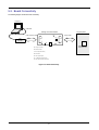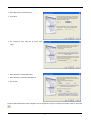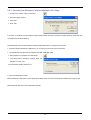
1
To our customers,
Old Company Name in Catalogs and Other Documents
On April 1st, 2010, NEC Electronics Corporation merged with Renesas Technology
Corporation, and Renesas Electronics Corporation took over all the business of both
companies. Therefore, although the old company name remains in this document, it is a valid
Renesas Electronics document. We appreciate your understanding.
Renesas Electronics website: http://www.renesas.com
April 1st, 2010
Renesas Electronics Corporation
Issued by: Renesas Electronics Corporation (http://www.renesas.com)
Send any inquiries to http://www.renesas.com/inquiry.
Notice
1.
2.
3.
4.
5.
6.
7.
All information included in this document is current as of the date this document is issued. Such information, however, is
subject to change without any prior notice. Before purchasing or using any Renesas Electronics products listed herein, please
confirm the latest product information with a Renesas Electronics sales office. Also, please pay regular and careful attention to
additional and different information to be disclosed by Renesas Electronics such as that disclosed through our website.
Renesas Electronics does not assume any liability for infringement of patents, copyrights, or other intellectual property rights
of third parties by or arising from the use of Renesas Electronics products or technical information described in this document.
No license, express, implied or otherwise, is granted hereby under any patents, copyrights or other intellectual property rights
of Renesas Electronics or others.
You should not alter, modify, copy, or otherwise misappropriate any Renesas Electronics product, whether in whole or in part.
Descriptions of circuits, software and other related information in this document are provided only to illustrate the operation of
semiconductor products and application examples. You are fully responsible for the incorporation of these circuits, software,
and information in the design of your equipment. Renesas Electronics assumes no responsibility for any losses incurred by
you or third parties arising from the use of these circuits, software, or information.
When exporting the products or technology described in this document, you should comply with the applicable export control
laws and regulations and follow the procedures required by such laws and regulations. You should not use Renesas
Electronics products or the technology described in this document for any purpose relating to military applications or use by
the military, including but not limited to the development of weapons of mass destruction. Renesas Electronics products and
technology may not be used for or incorporated into any products or systems whose manufacture, use, or sale is prohibited
under any applicable domestic or foreign laws or regulations.
Renesas Electronics has used reasonable care in preparing the information included in this document, but Renesas Electronics
does not warrant that such information is error free. Renesas Electronics assumes no liability whatsoever for any damages
incurred by you resulting from errors in or omissions from the information included herein.
Renesas Electronics products are classified according to the following three quality grades: “Standard”, “High Quality”, and
“Specific”. The recommended applications for each Renesas Electronics product depends on the product’s quality grade, as
indicated below. You must check the quality grade of each Renesas Electronics product before using it in a particular
application. You may not use any Renesas Electronics product for any application categorized as “Specific” without the prior
written consent of Renesas Electronics. Further, you may not use any Renesas Electronics product for any application for
which it is not intended without the prior written consent of Renesas Electronics. Renesas Electronics shall not be in any way
liable for any damages or losses incurred by you or third parties arising from the use of any Renesas Electronics product for an
application categorized as “Specific” or for which the product is not intended where you have failed to obtain the prior written
consent of Renesas Electronics. The quality grade of each Renesas Electronics product is “Standard” unless otherwise
expressly specified in a Renesas Electronics data sheets or data books, etc.
“Standard”:
8.
9.
10.
11.
12.
Computers; office equipment; communications equipment; test and measurement equipment; audio and visual
equipment; home electronic appliances; machine tools; personal electronic equipment; and industrial robots.
“High Quality”: Transportation equipment (automobiles, trains, ships, etc.); traffic control systems; anti-disaster systems; anticrime systems; safety equipment; and medical equipment not specifically designed for life support.
“Specific”:
Aircraft; aerospace equipment; submersible repeaters; nuclear reactor control systems; medical equipment or
systems for life support (e.g. artificial life support devices or systems), surgical implantations, or healthcare
intervention (e.g. excision, etc.), and any other applications or purposes that pose a direct threat to human life.
You should use the Renesas Electronics products described in this document within the range specified by Renesas Electronics,
especially with respect to the maximum rating, operating supply voltage range, movement power voltage range, heat radiation
characteristics, installation and other product characteristics. Renesas Electronics shall have no liability for malfunctions or
damages arising out of the use of Renesas Electronics products beyond such specified ranges.
Although Renesas Electronics endeavors to improve the quality and reliability of its products, semiconductor products have
specific characteristics such as the occurrence of failure at a certain rate and malfunctions under certain use conditions. Further,
Renesas Electronics products are not subject to radiation resistance design. Please be sure to implement safety measures to
guard them against the possibility of physical injury, and injury or damage caused by fire in the event of the failure of a
Renesas Electronics product, such as safety design for hardware and software including but not limited to redundancy, fire
control and malfunction prevention, appropriate treatment for aging degradation or any other appropriate measures. Because
the evaluation of microcomputer software alone is very difficult, please evaluate the safety of the final products or system
manufactured by you.
Please contact a Renesas Electronics sales office for details as to environmental matters such as the environmental
compatibility of each Renesas Electronics product. Please use Renesas Electronics products in compliance with all applicable
laws and regulations that regulate the inclusion or use of controlled substances, including without limitation, the EU RoHS
Directive. Renesas Electronics assumes no liability for damages or losses occurring as a result of your noncompliance with
applicable laws and regulations.
This document may not be reproduced or duplicated, in any form, in whole or in part, without prior written consent of Renesas
Electronics.
Please contact a Renesas Electronics sales office if you have any questions regarding the information contained in this
document or Renesas Electronics products, or if you have any other inquiries.
(Note 1) “Renesas Electronics” as used in this document means Renesas Electronics Corporation and also includes its majorityowned subsidiaries.
(Note 2) “Renesas Electronics product(s)” means any product developed or manufactured by or for Renesas Electronics.
User’s Manual
Voltage Conversion Board
User’s Manual
RENESAS SINGLE-CHIP 8-BIT CMOS
MICROCOMPUTER
740 FAMILY
Rev.2.00 2007.07
Table of Contents
Chapter 1. Preface .................................................................................................................................................. 1
Chapter 2. Precautions ........................................................................................................................................... 2
Chapter 3. Purpose ................................................................................................................................................. 3
Chapter 4. Power Supply ........................................................................................................................................ 4
4.1. Requirements ............................................................................................................................................... 4
Chapter 5. Layout and Connectivity........................................................................................................................ 5
5.1. Component Layout ....................................................................................................................................... 5
5.2. Board Connectivity ....................................................................................................................................... 6
Chapter 6. Programming......................................................................................................................................... 7
6.1. Introduction ...................................................................................................................................................... 7
6.2. Adjusting a VPP Voltage...................................................................................................................................... 7
6.2.1. Connecting a Voltage Conversion Board .......................................................................................................... 7
6.2.2. Creating a new Project Workspace.................................................................................................................. 8
6.2.3. Connecting Flash Development Toolkit and Adjusting the VPP Voltage ................................................................. 10
6.3. Programming to QzROM ................................................................................................................................... 11
6.3.1. Connecting a Voltage Conversion Board and a Target ....................................................................................... 11
6.3.2. Connecting Flash Development Toolkit........................................................................................................... 11
6.3.3. Programming ........................................................................................................................................... 12
6.3.4. Protect setting .......................................................................................................................................... 12
Chapter 7. Pin Handling ........................................................................................................................................ 14
7.1. Example 1................................................................................................................................................... 14
7.2. Example 2................................................................................................................................................... 15
7.3. Example 3................................................................................................................................................... 16
Chapter 8. Additional Information ......................................................................................................................... 17
ii
Chapter 1. Preface
Cautions
This document may be, wholly or partially, subject to change without notice.
All rights reserved. Duplication of this document, either in whole or part is prohibited without the written permission of Renesas
Solutions Corporation.
Trademarks
All brand or product names used in this manual are trademarks or registered trademarks of their respective companies or
organisations.
Copyright
© Renesas Solutions Corp. 2007. All rights reserved.
© Renesas Technology Europe Ltd. 2007. All rights reserved.
© Renesas Technology Corp. 2007. All rights reserved.
Website:
http://www.renesas.com/
(Global)
http://www.eu.renesas.com/
(Europe)
Glossary
CPU
Central Processing Unit
PC
Personal Computer
FDT
Flash Development Toolkit
VCB
Voltage Conversion Board
LED
Light Emitting Diode
1
Chapter 2. Precautions
Please be sure to read Notes shown below before using this tool.
Warning
This Voltage Conversion Board is an optional programming tool for QzROM microcontrollers, and cannot be used for
Flash microcontrollers. When connecting the Voltage Conversion Board to CPU Board, the Voltage Conversion Board and
CPU Board may be damaged. Therefore, do not connect the Voltage Conversion Board to CPU Board contained in Renesas
Starter Kit.
Warning
This Voltage Conversion Board builds in the voltage conversion circuit for VPP supply generation. Therefore, do not
connect the Voltage Conversion Board to a User Target with the conversion circuit for VPP supply. Connection with such a
User Target, may cause the Voltage Conversion Board and User Target to be damaged.
Warning
This Voltage Conversion Board has the IDC connector for connecting the E8a and User Target mounted, and these
connectors are the same form. Please be sure to connect E8a to the connector “CN2” on Voltage Conversion Board. When
connecting the Voltage Conversion Board to connector CN1 on Voltage Conversion Board, the Voltage Conversion Board
and E8a may be damaged.
>> Please refer to Section 5.2.
Warning
Before using Voltage Conversion Board, the user must adjust a VPP level using the potentiometer “VR1” on the Voltage
Conversion Board. If the Voltage Conversion Board is used without adjusting the VPP level, programming the QzROM
microcontroller may not be performed properly. Also, the microcontroller may be damaged.
>> Please refer to Section 6.2.
2
Chapter 3. Purpose
This Voltage Conversion Board is a programming option tool for Renesas 740 QzROM microcontrollers.
Features include:
•
Programming Circuit. (via E8a emulator)
•
Voltage Conversion Circuit for VPP Power Supply Generation.
This manual describes the technical details of the Voltage Conversion Board hardware. Moreover, this manual provide details of the
programming method and programming environment.
3
Chapter 4. Power Supply
4.1. Requirements
This Voltage Conversion Board operates from a 3V to 5V power supply. Power is supplied from the E8a or user target system. The
Voltage Conversion Board uses this supply to generate VPP supply through a voltage conversion circuit on Voltage Conversion Board.
The power jack (J1) for VPP supply generation is provided for the user target system. Normally, the power is provided from E8a or the
user target system. If their drive capability is not enough, external power for VPP supply of the user target system can be provided from
the power jack. The input voltage range of the external power for VPP supply is 9.0V to 12.0V.
Figure 4-1: Power Jack (J1) Polarity
4
Chapter 5. Layout and Connectivity
5.1. Component Layout
The following diagram shows the top layer component layout of the board.
GND Test Pin (TP1)
* Thru-hole
E8a Connector (CN2)
Target Connector (CN1)
Power LED (D2)
GND Test Pin (TP2)
VPP Adjust (VR1)
VPP Power Test Pin (TP4)
Power Jack (J1)
* Thru-hole
* Thru-hole
Figure 5-1: Component Layout
5
5.2. Board Connectivity
The following diagram shows the board connectivity.
Host PC
USB cable
Voltage Conversion Board
Target System
TP1
User interface cable
Target cable
VR1
E8a
emulator
CN2
TP2
CN1
J1
D2
TP4
QzROM
Microcontroller
CN1: Target connector
CN2: E8a connector
J1: Power jack (9to12VDC)
D2: Power LED
VR1: VPP power adjust
TP1, 2: GND test pin (Thru-hole)
TP4: VPP power test pin (Thru-hole)
Figure 5-2 : Board Connectivity
6
Chapter 6. Programming
6.1. Introduction
Renesas’s Flash Development Toolkit is a dedicated flash programming software for Renesas F-ZTAT microcontrollers, which offers a
sophisticated and easy-to-use Graphical User Interface. Flash Development Toolkit will have been installed during the installation of the
software support for the Renesas Starter Kit product. This manual will describe the stages required to program the code.
6.2. Adjusting a VPP Voltage
Before using Voltage Conversion Board, user must adjust a VPP voltage level using the potentiometer “VR1” on the Voltage
Conversion Board. If the Voltage Conversion Board is used without adjusting the VPP level, programming the QzROM
microcontroller may not be performed properly. Also, the microcontroller may be damaged.
Therefore, please be sure to adjust the VPP voltage level according to the procedure shown in the following sections.
6.2.1. Connecting a Voltage Conversion Board
This section shows how to connect the Voltage Conversion Board.
• Connect E8a to Host PC by the USB cable.
• Connect Voltage Conversion Board to E8a by the User interface cable.
• Check that the User interface cable is not connected to the Target Connector (CN1) on Voltage Conversion Board. If it is connected,
please reconnect with the E8a Connector (CN2) on Voltage Conversion Board.
• Check that the user target system is not connected to Voltage Conversion Board. If it is connected, please disconnect the user target
system from Voltage Conversion Board.
7
6.2.2. Creating a new Project Workspace
• Start Flash Development Toolkit from the Windows Start Menu, Start | All Programs | Renesas | Flash Development Toolkit 4.00 |
Flash Development Toolkit 4.00.
• Open a new workspace from the [File -> New Workspace…] menu or select ‘Create a new project workspace’ when presented with
the ‘Welcome!’ dialog.
The example above shows the New Project Workspace dialog.
• Enter a Workspace Name; all your files will be stored within a folder called …\Workspaces\<your_name>
• The project name field will be pre-filled to match the workspace name above; you can change this name if you wish.
• Click <OK> to start the Flash Development Toolkit Project Generator wizard.
• Select from a device type list the QzROM microcontroller
that you use.
• Click <Next>.
8
• Select “E8a” as the communication port.
• Click <Next>.
• The “Connection Type” dialog will be shown. Click
<Next>.
• Select “Automatic” as the protection level.
• Select “Advanced” as the output massage level.
• Click <Finish>.
The above Flash Development Toolkit configuration can be changed later using the <Configure Flash Project> button on the toolbar.
9
6.2.3. Connecting Flash Development Toolkit and Adjusting the VPP Voltage
• Click the <FDT Connect> button on the toolbar.
• Set ‘Power supply’ checkbox.
• Select ‘5.0V’.
• Press <OK>.’
If connection is completed, Flash Development Toolkit’s Output window will display ‘Connection complete’. Moreover, Power LED (D2)
on Voltage Conversion Board lights up.
The following step shows the VPP adjustment using the potentiometer (VR1) on Voltage Conversion Board.
• Check the voltage level between a GND test pin (TP1 or TP2) and a VPP test pin (TP4) using a tester.
• Turn potentiometer and adjust the VPP voltage level to 7.8V – 8.0V (Typ. 7.9V).
• When adjustment is completed, click <Disconnect>.
• If the dialog shown to the right is displayed, select <No
Protection> and click <OK>.
This is described in detail by Section 6.2.4.
• Close Flash Development Toolkit.
Flash Development Toolkit retains a power supply setting until the project is closed. This setting will be initialized by closing a project.
After following the steps above, VPP adjustment is complete.
10
6.3. Programming to QzROM
6.3.1. Connecting a Voltage Conversion Board and a Target
This section shows how to connect the Voltage Conversion Board to a user target system.
• Connect E8a to Host PC by the USB cable.
• Connect Voltage Conversion Board to E8a by the User interface cable.
• Connect target to Voltage Conversion Board by the Target cable.
If you provide the power from the target system, or when you provide the VPP power from the power jack (J1) on the Voltage
Conversion Board, please provide the power at this time.
6.3.2. Connecting Flash Development Toolkit
• Start Flash Development Toolkit from the Windows Start Menu and open the project workspace created with the Section 6.2.2.
• Click the <FDT Connect> button on the toolbar.
• If the E8 is to provide the power to the Voltage Conversion
Board and user target, select “Power Supply”. Otherwise
provide the power supply.
• Select “5.0V” or “3.3V” then click <OK> if “Power Supply”
is selected, otherwise click <OK>.
If connection is completed, Flash Development Toolkit’s Output window will display ‘Connection complete’. Moreover, Power LED (D2)
on Voltage Conversion Board lights up.
11
6.3.3. Programming
• Right click on the project listed in the left hand pane and
select “Add Files…”.
• Add the download file.
• Double click the download file added to the left hand
pane.
• Click the <Download Active File> button on the toolbar.
The download file will be programmed to the QzROM
microcontroller.
6.3.4. Protect setting
QzROM also introduces the concept of Security Protection into Flash Development Toolkit, which is optionally set as Flash Development
Toolkit disconnects (Note: once set, this cannot be undone).
The majority of devices have two levels of protection: Full (which prevents any later reconnection to the device) or None (which allows
reconnection normally). Newer devices have more levels – allowing a partial protection of the device and yet still allowing a later
connection (but with the protected data region masked).
There are three options for the setting of security protection:
Automatic
Flash Development Toolkit will protect the device as it disconnects. The level of protection will be determined when Automatic is initially
selected, typically ‘Full’. If the device offers multiple levels of protection then a dialog will appear to allow the user to select the level that
should automatically be applied.
12
Prompt
Flash Development Toolkit will ask what to do during the disconnect stage, i.e. whether to protect or not. The choice is between full
protection (or other levels if supported by the device) or no protection at all. The default is ‘No Protection’.
None
Flash Development Toolkit will not protect the device on disconnect.
• Select a protect option.
• Click the <Disconnect> button on toolbar.
If you have selected ‘Prompt’, the dialog shown to the right
will be displayed.
• Select protection type by this dialog.
• Click <OK>.
After following the steps above, QzROM programming is completed.
13
Chapter 7. Pin Handling
This chapter shows the programming pin handling which is used by the Voltage Conversion Board and E8a. Note that pin handling
varies depending on the QzROM microcontroller used.
7.1. Example 1
This Example shows pin handling of 38D5/38D2 Group (OSCSEL=”H”).
Figure 7-1 : Example of pin handling 1
VCB Connector
38D5
38D2
CN1
ESCLK (Pin1)
P42/SCLK1
P31/SCLK2
ESPGMB (Pin4)
P43/SRDY1
P30/SRDY2
ESDA (Pin7)
P41/TxD
P32/TxD2
Table 7-1: Additional table 1
14
7.2. Example 2
This Example shows pin handling of 38D5/38D2 Group (OSCSEL=”L”) and 3803H/3850A/3858/7544/7545/7546/7547/7548/7549 Group.
Figure 7-2 : Example of pin handling 2
VCB Connector
3803H
CN1
3850A
38D5
38D2
7544
7545
3858
7546
7547
ESCLK (Pin1)
P46/SCLK1
P43/INT2
P42/SCLK1
P31/SCLK2
P12/SCLK
P20/INT0
P12/SCLK1
VPP (Pin3)
CNVSS
CNVSS
OSCSEL
OSCSEL
CNVSS
CNVSS
CNVSS
ESPGMB (Pin4)
P47/SRDY1
P40/CNTR1
P43/SRDY1
P30/SRDY2
P10/RxD
P06/KEY6
P10/RxD1
ESDA (Pin7)
P45/TxD1
P42/INT1
P41/TxD
P32/TxD2
P11/TxD
P07/KEY7
P11/TxD1
Table 7-2: Additional table 2-1
VCB Connector
7548
---
---
---
---
---
---
CN1
7549
ESCLK (Pin1)
P06/SCLK
---
---
---
---
---
---
VPP (Pin3)
CNVSS
---
---
---
---
---
---
ESPGMB (Pin4)
P07/SRDY
---
---
---
---
---
---
ESDA (Pin7)
P10/AN0
---
---
---
---
---
---
Table 7-3: Additional table 2-2
15
7.3. Example 3
This Example shows pin handling of 3823 Group.
Figure 7-3 : Example of pin handling 3
16
Chapter 8. Additional Information
For details on how to use Flash Development Toolkit, refer to the Flash Development Toolkit manual available on the CD or from the web
site.
Online technical support and information is available at: http://www.renesas.com/renesas_starter_kits
Technical Contact Details
America:
[email protected]
Europe:
[email protected]
Japan:
[email protected]
General information on Renesas Microcontrollers can be found on the Renesas website at: http://www.renesas.com/.
17
Voltage Conversion Board
User's Manual
Publication Date
Rev.2.00
Jul.06,2007
Published by:
Renesas Solutions Corp.
4-1-6, Miyahara, Yodogawa-ku, Osaka City, 532-0003, Japan
©2007 Renesas Solutions Corp., Renesas Technology Europe Ltd. and Renesas Technology Corp.,
All Rights Reserved.
Voltage Conversion Board
User’s Manual
1753, Shimonumabe, Nakahara-ku, Kawasaki-shi, Kanagawa 211-8668 Japan
REJ10J1397-0200