1
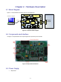
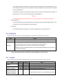
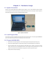
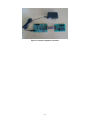
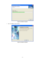
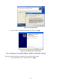
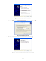
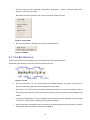
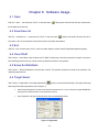
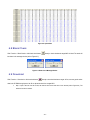
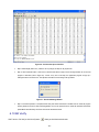
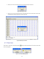
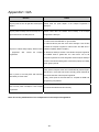
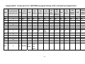
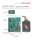
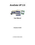
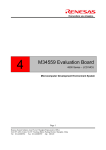
Compact Programmer for QzROM MCU
User's Manual
Rev 1.0
Revision date:April, 15, 2008
Table of Contents
Table of Contents ...................................................................................................................................................ii
Chapter 1. Compact Programmer Concept .......................................................................................................... 4
1.1 Overview....................................................................................................................................................... 4
1.2 System Requirements.................................................................................................................................. 4
1.3 Operating Environment .............................................................................................................................. 4
Chapter 2. Hardware Description ........................................................................................................................ 5
2.1 Block Diagram.............................................................................................................................................. 5
2.2 Components and Interface .......................................................................................................................... 5
2.3 Power Supply................................................................................................................................................ 5
2.4 Switches........................................................................................................................................................ 6
2.5 Jumper.......................................................................................................................................................... 6
2.6 LEDs ............................................................................................................................................................. 7
2.7 Target Connector.......................................................................................................................................... 7
Chapter 3. Hardware Usage ................................................................................................................................. 8
3.1 System Connection....................................................................................................................................... 8
3.2 Load Program Data...................................................................................................................................... 8
3.3 Program QzROM MCU................................................................................................................................ 8
Chapter 4. Software Installation ........................................................................................................................ 10
4.1 Install the PC Software ............................................................................................................................. 10
4.2 Install USB Bus Driver ............................................................................................................................. 13
4.3 Continue to Install USB to UART Controller Driver .............................................................................. 14
Chapter 5. Software Description ........................................................................................................................ 16
5.1 Main Window ............................................................................................................................................. 16
5.2 Menu Bar Structure................................................................................................................................... 16
5.3 Tool Bar Structure ..................................................................................................................................... 17
5.4 Data Area.................................................................................................................................................... 18
Chapter 6. Software Usage ................................................................................................................................. 19
6.1 Open............................................................................................................................................................ 19
6.2 Save/Save As............................................................................................................................................... 19
6.3 Exit.............................................................................................................................................................. 19
6.4 Clear RAM .................................................................................................................................................. 19
6.5 Erase Ext-Dataflash .................................................................................................................................. 19
6.6 Target Select............................................................................................................................................... 19
6.7 Upload......................................................................................................................................................... 20
6.8 Blank Check ............................................................................................................................................... 21
6.9 Download .................................................................................................................................................... 21
6.10 Bit Verify................................................................................................................................................... 22
6.11 Check Sum................................................................................................................................................ 23
ii
6.12 Protect....................................................................................................................................................... 24
6.13 Help Topics ............................................................................................................................................... 25
Appendix1: Q/A .................................................................................................................................................... 26
Appendix2: Used pins for QzROM programming with compact programmer................................................. 27
iii
Chapter 1. Compact Programmer Concept
1.1 Overview
The Compact Programmer can be used for QzROM MCU programming. It can support QzROM MCU on-board and off-board
programming at on-line mode or off-line mode.
1.2 System Requirements
In addition to the products listed below, prepare them before you use.
(1) Host computer
(2) CP board
(3) USB cable
(4) AC adapter
(5) MCU socket board
1.3 Operating Environment
Host computer operating environment is shown below:
Host Computer
IBM PC/AT compatible machine with USB
OS
Microsoft Windows 98SE/2000/XP
CPU
Pentium III 600MHz or newer
Memory
128MB or above
-4-
Chapter 2. Hardware Description
2.1 Block Diagram
Figure 2-1 is the representative connections from PC to user target board
E8 Connector
Voltage
Convert
Personal Computer
Reset
Control MCU
R5F21256
Power
Connector
Power
Error
Verify
Program
Blank
74LVC125
CP2102
Wire
Download
Compact Programmer
Figure 2-1 Connections Block Diagram
2.2 Components and Interface
The Figure 2-2 is representative of the Compact Programmer components layout and interface.
Figure 2-2 Components and Interface
2.3 Power Supply
•
Requirements
-5-
Target
Connector
Control S/W
USB
Connector
Target
Connector
M25P10
USB Cable
Target
Board
This Compact Programmer operates from a 5V power supply. A diode provides reverse polarity protection only if a
current limiting power supply is used. When operates the Compact Programmer by PC, the power can be supplied
by PC through USB cable.
The Compact Programmer has a centre positive supply connector using a 2.1mm barrel power jack, through it, an
adapter (220V AC – 5V DC) can be used to supply the Compact Programmer.
Warning
•
The Compact Programmer is neither under nor over voltage protected. Use a centre positive supply for it.
Power On Behaviour
The Compact Programmer has pre-programmed the monitor program into the control MCU (R5F21256/58). As soon
as powering on it, the user LED will light for a while and then off.
•
Power Option
The Compact Programmer can supply 3V or 5V power for target board by one jumper (refer to 3.4).
2.4 Switches
There are two switches located on the Compact Programmer. The function of each switch is shown in Table 2-1.
Switch
RESET
Function
When pressed, the control MCU on the Compact Programmer is reset.
When pressed, the compact programmer will execute the following operation:
1) Check if target MCU is blank (data=0xFF), otherwise change another blank MCU;
Download
2) Program the specified memory contents of control MCU into the target MCU;
3) Read the contents of the target MCU memory and compare with the specified memory of control MCU to
verify if keep consistently.
Table 2-1 Switch Functions
Note: The “Download” switch is invalid when compact programmer connected to PC.
2.5 Jumper
There are two jumpers located on the Compact Programmer. The connection of each jumper is shown in Table 2-2.
MCU
Jumper
Connection
Action
M34508/09, M34559/455A,
R5G0C22, R5G0C24,
J4
J6
J4
J6
2---3
2---3
1---2
1---2
Compact Programmer supply 3V DC for target board programming
SDA data line select pull-down resistor (1K)
Compact Programmer supply 5V DC for target board programming
SDA data line select pull-up resistor (4.7K)
J4
1---2
Compact Programmer supply 5V DC for target board programming
M34283
M37544/45, M37546/47,
M37548/49, M3850A/58,
M38D2/D5, M3823/03H,
-6-
R5G0C30, R5G0C31,
R5G0C32, R5G0C33,
R5G0C34, R5G0C40,
R5G0C41, R5G0C50,
R5G0C51, R5G0C52
J6
1---2
SDA data line select pull-up resistor (4.7K)
Table 2-2 Jumper Connections
2.6 LEDs
There are five LEDs on the Compact Programmer. Table 2-3 below, describes the LED status and functions.
Operation
Power On
Normal
LED Status
“Power” on
When power on the Compact Programmer, LED “Power” on
“Program” blink,
LED “Program” and “Verify” blinking while downloading, if download
“Verify” blink
successfully, “Program” and “Verify” on for 5s, and then off; LED “Blank”
“Blank” blink
blinking while execute blank check operation.
On-line: If communication error happens, LED “Error” on;
“Error” on
Program
Error
Description
Off-line: If the serial Flash is blank, LED “Error” on.
“Blank” on, “Error” on
If the MCU is not blank, LED “Blank” on and “Error” on;
“Program” on, “Error” on
If program error happens, LED “Program” and “Error” on;
“Verify” on, “Error” on
If bit verify error happens, LED “Verify” and “Error” on.
All of LED on (off-line)
The QzROM MCU is protected or block protection, no target.
Table 2-3 LED Status and Functions Description
2.7 Target Connector
Figure 2-3 below shows the target connector pin assignment.
Pin2
Pin14
Pin1
Pin13
Figure 2-3: Pin Assignment
About used pins for QzROM programming with compact programmer, please refer to Appendix 2.
-7-
Chapter 3. Hardware Usage
3.1 System Connection
Connect PC and Compact Programmer with USB cable (refer to Figure 3-1), the PC control software will display connection
success message if PC find the Compact Programmer, otherwise disconnect the cable and connect again. About the usage of PC
control software, please refer to the manual of Compact Programmer Software.
Figure 3-1 System Connections
3.2 Load Program Data
Load the data to be written into target MCU and download them to the Serial Flash external. You may also program QzROM MCU
by PC control software directly, please refer to the software part of this manual for detail.
3.3 Program QzROM MCU
•
Disconnect PC and Compact Programmer, connect Compact Programmer and target board (refer to Figure 3-2);
•
Power on the Compact Programmer, if system starts up normally, all of user LEDs will light on for 5s and then off;
•
Push the “Download” switch, the monitor program will execute “Blank Check”, “Program” and “Bit Verify” operation
orderly, if there are not errors, corresponding LED will blink, and the Program and Verify LED will light on for 1s after
program ends. About the LED’s status explanation and program error information, please refer to part 5
•
Change another user board and repeat (3);
-8-
Figure 3-2 Compact Programmer Connection
-9-
Chapter 4. Software Installation
4.1 Install the PC Software
•
Step 1: Run “setup.exe” from CD-ROM or operate according to screen indication when the installation CD automatically
runs. Click Next to continue installation Compact Programmer Version 1.6.
Figure 4-1: Compact Programmer Installation Window
•
Step 2: Click Change to modify path of the application program, then click Next to continue install.
Figure 4-2: Select Install Path
•
Step 3: Select shortcut folder location.
- 10 -
Figure 4-3: Modify the Start Menu Item
•
Step 4: Confirm the installation information, click Next to start copy files.
Figure 4-4: Copy Files to Your PC
•
Step 5: Copy files.
- 11 -
Figure 4-5: Installation Completed
•
Step 6: Click Finish to complete Installation.
Figure 4-6: Installation Completed
- 12 -
4.2 Install USB Bus Driver
The new hardware will be installed automatically at the first time to connect the CP to PC.
•
Step 1: Select install from a list or special location then click Next.
Figure 4-7: Install the Driver of USB Bus
•
Step 2: Click Browse and select “C:\windows\system32\drivers\” (depend on the OS), then click Next.
Figure 4-8: Designated the Drivers Path
•
Step 3: OS will install the USB bus driver to your computer. Click the button of Continue Anyway
- 13 -
Figure 4-9: Install USB Bus Driver
•
Step 4: The USB bus driver has been installed to your computer. Click Finish.
Figure 4-11: The USB Bus Driver has been Intalled.
4.3 Continue to Install USB to UART Controller Driver
After above, the OS will prompt you to install the driver of the USB to UART controller.
•
Step 5: Select install from a list or special location then click Next.
- 14 -
Figure 4-12: Install the USB to UART Controller Driver
•
Step 6: Click Browse and select “C:\windows\system32\drivers\” (depend on the OS), then click Next.
Figure 4-13: Designated the Drivers Path
•
Step 7: The driver of the USB to UART controller has been install to your PC. Click Finish.
Figure 4-14: The Driver of the USB to UART Controller has been Installed.
- 15 -
Chapter 5. Software Description
5.1 Main Window
Figure 5-1: Main Window
5.2 Menu Bar Structure
There are three menus of menu bar. The detail functions of the menus refer to the Chapter 6 description.
Figure 5-2: Menu Bar
•
File: This menu contains of “Open…”, “Save”, “Save As…” and “Exit”.
Note: Disable some menus operations in the menu bar, when those operations are forbid.
Figure 5-3: File Menu
- 16 -
•
Function: This menu contains of “Clear RAM”, “Goto Address”, “Target Select…”, “Upload…”, “Download”, “Blank Check”,
“Bit Verify”, “Check Sum” and “Protect”.
Note: Disable some menus operations in the menu bar, when those operations are forbid.
Figure 5-4: Function Menu
•
Help: This menu contains of “Help Topics” and “About Compact Programmer”.
Figure 5-5: Help Menu
5.3 Tool Bar Structure
There are nine buttons of tool bar. The detail functions of the buttons refer to the Chapter 6 description.
Note: Disable some operations in the tool bar, when those operations are forbid.
Figure 5-6: Tool Bar
•
Save: Save read data in a file. The compact Programmer for M34283 (4bits MCU) only support “.hex” file format. If
Select an invalid file the program will jump a warning window with doing nothing.
•
Open: Open a “.hex” file in the RAM. The compact Programmer only support “.hex” file format for M34283. If open an
invalid file the program will jump a warning window with doing nothing. If there is an active file, the download button is set
enabled.
•
Target Select: The target MCU or CP can be selected as download operation target. If target MCU is invalid, the target
can only be CP. Protect operation is enable only when target MCU is selected.
•
Upload: Upload data from target MCU. When click this button, the software will prompt enter start address, end address
and data length. After that click OK to upload data from target MCU.
- 17 -
Note: No matter the target select which one of CP/Target MCU, Compact Programmer only read data from target MCU
for security of source codes. And when the target MCU is protected, the upload operation will fail and the software will
pop up a message window to show the error type.
•
Blank Check: Before program a target MCU, Blank check should be operated for avoid program error. The result of blank
check will show in the message window.
•
Download: Click this button, the active data in RAM will download to recent target.
•
Bit Verify: After data download, select Bit Verify to compare the data in the target and in the RAM bit by bit. The result will
show in the message window.
•
Check Sum: After data download, select Check Sum to compare the Sum of download data in the target and the sum of
the PC RAM. The result will show in the message window.
•
Protect: If the target MCU is selected, the protect operation is set enabled. Click the protect button to protect the target
MCU. The operation result will show in the message window.
•
Goto Address: Click this button, Data Area will refresh display from a designated address.
5.4 Data Area
Figure 5-7: Data Area
- 18 -
Chapter 6. Software Usage
6.1 Open
Click File -> Open…, use shortcut key “Ctrl+O” or click open button
directly, select a Hex file and click open, the data of the
file will display in the data area.
6.2 Save/Save As
Click File -> Save/Save As…, use shortcut key “Ctrl+S” or click save button
directly, enter the file name and click OK to
save data in a file. The save operation can be used only after a successful read operation.
6.3 Exit
Click File -> Exit, use shortcut key “Ctrl+Q” or click save button directly to quit the Compact Programmer application program.
6.4 Clear RAM
Click Function -> Clear RAM to clear the data in the PC RAM. The data area of the main window also is cleared. If the read or
write operation generate some error, use this function can eliminate the effect of error operation.
6.5 Erase Ext-Dataflash
Click Function -> Erase Ext-Dataflash to clear the data of the CP. This operation will erase the content of the serial flash. The
download program will lose!
6.6 Target Select
Click Function -> Target Select or click Target Select button
directly to choice the download target. The program will prompt
select target in the select target window (refer to Figure 6-1).
•
Select Compact Programmer: The data of download file will download to CP. We can download to target QzROM MCU
through press the download button on the CP without PC support.
•
Select Target MCU: The data of download file will write to the QzROM MCU directly.
Figure 6-1: Target Select
- 19 -
6.7 Upload
Click Function -> Upload or click upload button
directly to do upload operation.
Note: No matter the target select which one of CP/Target MCU, Compact Programmer only read data from target MCU for security
of source codes. And when the target MCU is protected, the upload operation will fail and the software will pop up a message
window to show the error type.
•
Step 1: Click upload the software will prompt enter start address, end address and data length (refer to Figure 6-2). Enter
two items of the start address, end address and data length to upload designate QzROM area. Use default value read all
QzROM area of target MCU.
Figure 6-2: Enter Address
•
Step 2: Click OK to read out data of target MCU. On the message window we can find the progress of upload (refer to
Figure 6-3).
Figure 6-3: Upload Message Window
•
Step 3: After complete the upload operation, the data will display in blue in the data area of the main window (refer to
Figure 6-4). The other area will display with dummy data “FF”. And then the data can be saved in a hex file when press
save button.
- 20 -
Figure 6-4: Upload Data
6.8 Blank Check
Click Function -> Blank Check or click blank check button
directly to check whether the target MCU is blank. The result will
be shown in the message window (refer to Figure 6-5).
Figure 6-5: Blank Check Message Window
6.9 Download
Click Function -> Download or click download button
directly to download the data to target. At first, we must get the active
data in the PC RAM through open a hex file or upload the data from a target MCU.
•
Step 1: Open a hex file. If the file is valid, the data will show in the data area of main window (refer to Figure 6-6). The
download function is enabled.
- 21 -
Figure 6-6: Tool Bar when Open a Valid File
•
Step 2: Select target (refer to 6.5). If there is not any change, this step can be jumped over.
•
Step 3: Click Download button or menu bar to start download data to target. On the message window we can find the
progress of download (refer to Figure 6-7). If there is any error in this step, this application program will pop up a
message window to show the error. The operation information can be finding in the log textbox.
Figure 6-7: Download Message Window
•
Step 4: If download operation is compete, the Bit Verify and Check Sum buttons is enabled. We can check the program
result by these two functions. When select target MCU, we can use upload function to check the download result before
protect MCU. About Bit Verify and Check Sum will be described as below.
6.10 Bit Verify
Click Function -> Bit Verify or click bit verify button
directly to check the download result.
- 22 -
•
Bit Verify is correct: The check result will be shown in the message window (refer to Figure 6-8).
Figure 6-8: Bit Verify is Correct
•
Bit Verify is not correct: The check result will be shown in the message window. We can find the number of the error bytes.
The different bytes will redisplay original data in red (refer to Figure 6-9).
Figure 6-9: Bit Verify is not Correct
6.11 Check Sum
Click Function -> Check Sum or click check sum button
directly to check the download result. The check sum value will be
shown in the log textbox.
Figure 6-10: Check Sum Message Window
- 23 -
Figure 6-11: Check Sum Message Window
6.12 Protect
Click Function -> Protect or click protect button
to protect the target MCU. The operation result will be shown in the
message window.
•
Step 1: If MCU support block protection, select protection type at first. Click OK then program prompt to confirm protect
operation.
Figure 6-12: Protection Window
•
Step 2: Click OK to protect the target MCU.
- 24 -
Figure 6-13: Protect Confirm Window
•
Step 3: The result of operation will be shown in the message window.
Figure 6-14: Protect Message Window
6.13 Help Topics
Click Function -> Help Topics or press “F1” to show the help topics.
- 25 -
Appendix1: Q/A
Question
Answer
Why the power Led can not light after connect power
Please check the power adapter or the Compact Programmer is
adapter?
destroyed.
Why the yellow Led lamps and red Led lamp can not
Please confirm MCU and oscillator mount normally or the Compact
light for while and turn off after power on?
Programmer is destroyed.
1. Please confirm the USB cable is in good condition.
2. Please review the ports item in the device manager of the OS after
connects the Compact Programmer. Please confirm the USB driver is
Why the PC software always display “Please connect
installed completely. (Refer to Chapter 5)
a
3. Whether the COM port number of the “Renesas Compact Programmer
programmer”
after
connect
the
Compact
Programmer?
for QzROM” device is greater than 16? If this value is over 16, the
Compact Programmer can not be recognized. Please modify the COM port
number in the advanced setting option of the device property’s port setting
option group by manual.
Firstly, please modify the correct value of the ROM code protection Byte in
How to protect a 740 family MCU after download
automatically in off-line mode?
the Hex file or in the data area window. Secondly, please download the
data to the serial flash of the Compact Programmer.
Finally, please press the download button to complete the ROM code
programming and protection.
How much the power consumption of the Compact
Programmer?
It consume about 60mA when work normally.
Note: Do not any modification of the components on the Compact Programmer.
- 26 -
Appendix2: Used pins for QzROM programming with compact programmer
Signal
Compact Programmer
Target Header Pin No
4283
4508
R5G0C22
4509
4559
7544
7545
R5G0C24
R5G0C30
R5G0C32
7546
7547
R5G0C31
7548
7549
R5G0C33
3803
3823
R5G0C52
R5G0C34
38D2
R5G0C50
3850A/58
38D5
R5G0C51
R5G0C40
R5G0C41
SCLK
1
E0
P21
P21
D3
P12
P20
P12
P06
P46
P42
P31
P42
P43
GND
2
VSS
VSS
VSS
VSS
VSS
VSS
VSS
VSS
VSS
VSS
VSS
VSS
VSS
VPP
3
E2
CNVss
CNVss
CNVss
CNVss
CNVss
CNVss
CNVss
CNVss
CNVss
CNVss
CNVss
CNVss
PGMB
4
G1
D3
D3
D2
P10
P06
P10
P07
P47
P43
P30
P43
P40
NC
5
NC
6
SDA
7
G0
P20
P20
D4
P11
P07
P11
P10
P45
P44
P32
P41
P42
VCC
8
VDD
VDD
VDD
VDD
VCC
VCC
VCC
VCC
VCC
VCC
VCC
VCC
NC
9
NC
10
NC
11
NC
12
RESET
13
RESET
RESET
RESET
RESET
RESET
RESET
RESET
RESET
VCC
VDDR
RESET
Xin/Xcin
GND
14
Xin
Xin RESET
Xin
P20/21
RESET
VDCE
RESET
- 27 -
Compact Programmer for QzROM MCU
User’s Manual
Publication Date
Rev 1.0 April 15, 2008