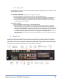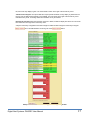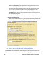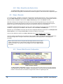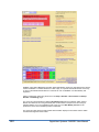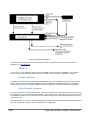
1
DASDEC II Digital/Analog Emergency Alert System Encoder/Decoder User Manual Model DASDEC-1EN Version 2.6-0 March 27, 2015 Digital Alert Systems A Division of Monroe Electronics Inc. 100 Housel Ave Lyndonville, NY 14098 www.digitalalertsystems.com FCC Information FCC ID: R8VDASDEC-1EN The DASDEC is fully compliant with FCC Part 11. This equipment has been tested and found to comply with the limits for a Class A digital device, pursuant to Part 15 of the FCC Rules. These limits are designed to provide reasonable protection against harmful interference when the equipment is operated in a commercial environment. This equipment generates, uses, and can radiate radio frequency energy and, if not installed and used in accordance with the instruction manual, may cause harmful interference to radio communications. Operation of this equipment in a residential area is likely to cause harmful interference in which case the user will be required to correct the interference at his/her own expense. Copyright © 2004-2015 Digital Alert Systems A Division of Monroe Electronics Inc. All Rights Reserved DASDEC is a Trademark of Digital Alert Systems Chyron CODI is a Trademark of Chyron Corporation. NDU is a Trademark of Vela Inc. Cable Envoy and CEMS are Trademarks of Monroe Electronics VDS-840 is a Trademark of Keywest Technology. SAGE & ENDEC are registered Trademarks of Sage Alerting Systems, Inc. SqueezeMax is a Trademark of Utah Scientific Inc. All other Trademarks are hereby acknowledged. CONTACT INFORMATION: Digital Alert Systems A Division of Monroe Electronics Inc. 100 Housel Ave Lyndonville, NY 14098 Sales & Technical support: Office: 585-765-1155 Table of Contents INTRODUCTION TO THE DASDEC II and the USER MANUAL ............................................................... 1 The Formatting of this Manual ................................................................................................................. 2 Organization of Manual for Setting up your DASDEC II .......................................................................... 2 Conventions used in this Manual (Symbols, Links, Screenshots, Notes) ................................................ 2 *****App-notes to help you configure your DASDEC***** ....................................................................... 3 1 DASDEC II Hardware ......................................................................................................................... 4 1.1 Introduction ................................................................................................................................... 4 1.2 Front Panel ................................................................................................................................... 4 1.2.1 1.2.2 2 LCD ..................................................................................................................................................... 4 Status LED .......................................................................................................................................... 5 1.3 Back Panel .................................................................................................................................... 5 Setup: Hardware ................................................................................................................................ 6 2.1 Audio Wiring ................................................................................................................................. 6 2.2 AES Digital Audio Wiring .............................................................................................................. 6 2.3 Video Wiring ................................................................................................................................. 7 2.4 General Purpose Input / Output (GPIO) ....................................................................................... 7 2.4.1 Optional Expansion GPIO ................................................................................................................... 8 2.5 Serial Port Wiring .......................................................................................................................... 8 2.6 MPEG Encoder Card Wiring ......................................................................................................... 9 3 DASCEC II Server Interface............................................................................................................. 10 3.1 Power Up, User Interface and Initial Setup ................................................................................ 10 3.1.1 3.1.2 3.2 3.3 Web Server Login ....................................................................................................................... 11 DASDEC II Page Organization, Web Interface and Navigation ................................................. 12 3.3.1 3.3.2 3.3.3 3.3.4 3.3.5 4 Directly connecting a networked host computer ................................................................................ 10 LAN connection with a networked host computer ............................................................................. 11 DASDEC II Page Header .................................................................................................................. 12 Interactive DASDEC II Page ............................................................................................................. 12 Standard Links at Bottom of Page .................................................................................................... 12 Web Interface and Navigation ........................................................................................................... 13 How to Make Changes and Update .................................................................................................. 13 Setup: Web Interface ....................................................................................................................... 15 4.1 Setup > Server: Setup Server..................................................................................................... 15 4.1.1 4.1.2 4.1.3 4.1.4 Main/License: Server Name & License Key Configuration ................................................................ 15 Configuration Management: Server Configuration Management ...................................................... 20 Upgrade: Server Software Upgrade .................................................................................................. 22 Options.............................................................................................................................................. 24 4.2 Setup > Network: Setup Network ............................................................................................... 24 4.3 4.4 4.5 Setup > Time: Server Date and Time Configuration .................................................................. 31 Setup > Users ............................................................................................................................. 32 Setup > Email ............................................................................................................................. 35 4.6 Setup > Audio ............................................................................................................................. 38 4.7 Setup Video/CG > Video/Character Generator Configuration .................................................... 53 4.2.1 4.2.2 4.2.3 4.5.1 4.5.2 4.5.3 4.5.4 4.6.1 4.6.1 4.6.2 4.6.3 Configuration: Server Network Configuration .................................................................................... 24 Security: Server Network Security Configuration .............................................................................. 29 Proxy ................................................................................................................................................. 31 Email Server ..................................................................................................................................... 35 Event Email ....................................................................................................................................... 36 Decoder Email .................................................................................................................................. 37 Encoder Email ................................................................................................................................... 38 Audio Output Levels/Tests: Direct Audio Output Levels and Tests ................................................... 39 Radio Tuners .................................................................................................................................... 42 Decoder Audio: Alert Decoding Audio Configuration ........................................................................ 44 Encoder Audio .................................................................................................................................. 50 4.7.1 4.7.2 4.7.3 4.7.4 4.8 Setup > Decoder: Setup Decoder Forwarding Options .............................................................. 60 4.9 Setup > Encoder ......................................................................................................................... 76 4.10 Setup > Net Alerts: Setup Network Alert Protocol Options ........................................................ 85 4.11 4.12 Setup > GPIO: Setup General Purpose IO Options ................................................................. 110 Setup > Printer: Setup Printer................................................................................................... 114 4.8.1 4.8.2 4.8.3 4.8.4 4.8.5 4.9.1 4.9.2 4.9.3 4.10.1 4.10.2 4.10.3 4.10.4 4.10.5 4.10.6 4.10.7 4.12.1 4.12.2 5 Main Serial ........................................................................................................................................ 53 USB Serial 1 through 4 ..................................................................................................................... 54 Serial port protocols .......................................................................................................................... 56 Video Out .......................................................................................................................................... 59 Forwarding: Decoder Forwarding Configuration ............................................................................... 61 Local Access Forwarding .................................................................................................................. 71 Custom MSG Forwarding .................................................................................................................. 74 Demo Decode/Forwarding ................................................................................................................ 75 Other: Setup Decoder Option Links .................................................................................................. 76 General: Main Encoder Configuration ............................................................................................... 76 Required Tests .................................................................................................................................. 82 Other ................................................................................................................................................. 84 DVS 168............................................................................................................................................ 85 EAS NET........................................................................................................................................... 87 CAP Decode ..................................................................................................................................... 95 DVS644 (SCTE18) ............................................................................................................................ 99 Stream MPEG ..................................................................................................................................104 Net CG .............................................................................................................................................106 Net GPIO: Configure NET GPIO Clients ..........................................................................................106 Connecting to a Network Computer or Via USB ..............................................................................114 Configuration ....................................................................................................................................115 4.13 Setup > Alert Storage: Setup Storage Management Options .................................................. 116 Decoder ........................................................................................................................................... 118 5.1 Incoming Alerts ......................................................................................................................... 118 5.2 Incoming/Decoded Alerts.......................................................................................................... 119 5.2.1 5.3 Incoming & Incoming/Decoded Alerts: Multistation Mode ................................................................126 Forwarded Alerts ...................................................................................................................... 128 5.3.1 Forwarded Alerts: Multistation Mode ................................................................................................128 5.4 Originated/Forwarded Alerts ..................................................................................................... 129 5.5 All Alerts .................................................................................................................................... 130 6 Encoder ........................................................................................................................................... 131 6.1 Send EAS ................................................................................................................................. 131 6.1.1 6.1.2 6.1.3 General EAS ....................................................................................................................................131 One-Button EAS ..............................................................................................................................138 Custom Message .............................................................................................................................141 6.2 Originated Alerts ....................................................................................................................... 143 6.3 Originated & Forwarded Alerts ................................................................................................. 143 6.4 All Alerts .................................................................................................................................... 143 7 Server .............................................................................................................................................. 144 7.1 Server > Help: Server Help....................................................................................................... 144 7.1.1 7.1.2 7.1.3 7.1.4 About DASDEC II-1EN.....................................................................................................................144 About EAS: The Emergency Alert System .......................................................................................144 EAS Message Protocol ....................................................................................................................144 EAS Codes: EAS Code Table ..........................................................................................................144 7.2 Server > Status: DASDEC II Server Status .............................................................................. 144 7.3 Server > Logs: Server Logs ...................................................................................................... 145 7.2.1 7.2.2 7.2.3 7.2.4 7.2.5 7.2.6 7.2.7 7.3.1 7.3.2 Main .................................................................................................................................................144 Network ............................................................................................................................................144 Operating System ............................................................................................................................145 USB..................................................................................................................................................145 CPU .................................................................................................................................................145 PCI ...................................................................................................................................................145 IO .....................................................................................................................................................145 Web Session Log: DASDEC II Emergency Alert System Encoder/Decoder Platform ......................145 Operation Log ..................................................................................................................................145 7.3.3 7.3.4 7.3.5 7.3.6 Operating System Log .....................................................................................................................145 Security Log .....................................................................................................................................146 Boot Log...........................................................................................................................................146 Email Log .........................................................................................................................................146 7.4 Server > DebugLogs: Server DebugLogs ................................................................................ 146 Typical Tasks .......................................................................................................................................... 147 When Your DASDEC Receives (Decodes) an Alert ............................................................................ 147 Originating/Encoding an Alert .............................................................................................................. 150 Retrieving the Logged Alerts in your DASDEC .................................................................................... 153 Retrieving your DASDEC OpLog ......................................................................................................... 154 Installing a license key ......................................................................................................................... 154 Backing up the DASDEC configuration file .......................................................................................... 154 Uploading an audio file in a DASDEC .................................................................................................. 155 Appendix ................................................................................................................................................. 156 DASDEC II Hardware and Software Specifications ............................................................................. 156 An Emergency Alert System Analog/Digital Encoder/Decoder Platform ...........................................................156 Hardware Specs ...............................................................................................................................................156 General Software Features/Specs ....................................................................................................................156 Decoder/Forwarding Features ..........................................................................................................................157 Encoder/Origination Features ...........................................................................................................................157 The Emergency Alert System .............................................................................................................. 157 Purpose 157 Operation 158 Management .....................................................................................................................................................158 What you need to do as a Broadcaster .............................................................................................................158 DASDEC II Peripherals ........................................................................................................................ 158 Vela NDU 159 Monroe Electronics Cable Envoy and CEMS 500/1000 ....................................................................................159 Keywest VDS-830/840/Starmu/Star-8 ..............................................................................................................159 Chyron CODI ....................................................................................................................................................159 Evertz Keyers ...................................................................................................................................................159 XBOB CG 160 BetaBrite LED sign ...........................................................................................................................................160 Other Character Generators .............................................................................................................................160 Utah Scientific SqueezeMax .............................................................................................................................161 EAS Protocol ........................................................................................................................................ 163 INTRODUCTION TO THE DASDEC II and the USER MANUAL The DASDEC II is an Emergency Alert System (EAS) Analog and Digital Encoder/Decoder platform. It is easy to use and relatively easy to learn. Generally, DASDEC Web interface screens (web pages) are selfexplanatory. Some users may be able to experiment with features with satisfactory results. However, DASDEC offers a large number of features and automated functions, plus a variety of shortcuts. Referring to this manual frequently will increase understanding and decrease learning time for successful, customized operation. All DASDEC II features are licensed. The full range of licensing permissions enables uses all available features. Limited licensing permission allows use of only the limited features. This manual reviews every DASDEC II screen and explains all DASDEC II features and options, regardless of the user's licensing permissions. We suggest you first review the manual's Table of Contents for an overview of features and tasks you need to complete. The Table of Contents presents the SETUP chapters in the most efficient way to configure DASDEC II step-by-step. To further assist you in setting up the DASDEC II platform, the manual has a checklist of tasks for DASDEC II Setup, in the order they should be completed. For best results, we strongly suggest first time users follow the instructions in order they are presented. Besides the Table of Contents, other Chapters of the manual will improve efficiency in set up for you like: An explanation of how DASDEC II screens are organized and how to navigate within DASDEC II. (Refer to Chapter 3.3 DASDEC II Page Organization, Web Interface and Navigation) An electronic version of the DASDEC II Manual is on the DAS website www.digitalalertsystems.com in both PDF and HTML formats. New features continue to be added to the DASDEC II platform. This manual is updated either in entirety, or by addendum, as new features become available. Your comments! Your comments on the usefulness of the manual, or suggestions for improvement, are welcome. Please let us know how we can serve you better. Send comments to Digital Alert Systems; specifics are on the second page of this manual A Note to the User: There are a lot of customization settings that are available for the DASDEC. Just because they are there does not mean they need to be turned on or enabled. KEEP YOUR DASDEC AS SIMPLE AS YOU CAN. Do not blindly turn on settings without knowing exactly how they will influence the operation of your DASDEC. There are many major settings that need to be turned on in order for the device to run properly, but there are many more minor settings that are there for the very specific needs of customers. Those minor settings should be watched with care as they will directly change the outcome of emergency alerts. Thank you for purchasing a DASDEC Digital Alert Systems: DASDEC User Manual 1 The Formatting of this Manual The manual describes all DASDEC II features, gives step-by-step instructions, and includes sample screen shots for quick reference. Chapters are organized starting with information and configurations of the hardware, and then leads to explaining the individual features of the software of your DASDEC II. Organization of Manual for Setting up your DASDEC II The SETUP chapters are in the order the tasks should be completed. The order guides a first time user through basic setup in the most efficient way to configure DASDEC II step-by-step and set up the DASDEC II platform. Common functions have stepby-step instructions. Example screen shots are included for quick reference. The SETUP chapters also thoroughly explain the individual parts associated with the DASDEC II. For best results, we strongly suggest first time users follow the setup instructions in the order or close to the order presented. After basic setup instructions, the manual continues with advanced configurations. When you complete basic set-up and the DASDEC II is operating successfully, you may wish to explore advanced features. These include detailed discussion of customizing features and integrating DASDEC II with other software applications. Conventions used in this Manual (Symbols, Links, Screenshots, Notes) To assist you in using this manual, we explain the following conventions. The symbol > indicates selecting a major tabbed page in the standard page header, followed by selecting a radio button and then a sub-tab. For example, Setup > Server > Upgrade means to first select the Setup tabbed page, then click the Server button, then click the Upgrade sub-tab. Screen names, or page titles, are in bold text. Different buttons and links will be presented as they are shown in a screenshot or as you would see them on the screen. For example, or and likewise, could be referenced to give direction to the user. Features on the interactive web page are typically presented from top to bottom within each section of the page. Many DASDEC II screens are divided into sections by one or more horizontal lines. The lines are intended to assist the user by grouping related functions similarly to the way a manual is divided into sections. A feature on the interactive page is typically presented in bold type, followed by a discussion of its use and instructions. A screen shot is an image to show the visible items on the monitor when certain DASDEC II selections are made or activity is ongoing. The image demonstrates a feature or particular setup. A screen shot is generally the result of following the instructions in the manual for a particular task. Each screen shot is labeled underneath with the name of the DASDEC II screen, or web page. A NOTE offers general information about the feature discussed or a suggestion to avoid problems. It looks like this: NOTE: This is an example of a Note. 2 Digital Alert Systems: DASDEC User Manual *****Appnotes to help you configure your DASDEC***** As of August 2012, here is a list of the available app-notes online to help you configure your DASDEC. Theses app-notes were created as quick guides to do certain configurations and work with the user manual to give you an advantage towards setting up your DASDEC correctly. To access them, go to http://www.digitalalertsystems.com/resources_application_notes.htm. There you can open a PDF file for each of these appnote topics listed. Interfacing your DASDEC™ with a Cayman Graphics® Power CG™ Configuring a DASEOC to send alerts to IPAWS E-Mail Configuration Expansion GPIO Specifications and Configuration DASDEC™/One-Net™ TCP/IP Port Table Disabling Text-To-Speech (TTS) on the DASDEC™ DASDEC™ EAS Monitoring Inputs Quick Wiring / Configuration Guide Step-by-Step Guide to Programming Your DASDEC™-II DASDEC™ Interfacing to Monroe Model R198 Networked Multichannel AES/EBU Audio Switcher EAS-Net Provisions for EAN and EAT Interfacing DASDEC with CAP Servers Setting up a Printer on the DASDEC™-II DASDEC™ interface with Inovonics 730 RDS Encoder MultiStation 2 and MultiStation 5 Setup DASDEC™ Interfacing to Broadcast Devices Inc. GPM-300 Series General Purpose Matrix Switcher DASDEC™ - Fox® Splicer™ Integration DASDEC™-II & SpectraRep® AlertManager™ Integration Development / Interface Requirements for DASDEC™ RS-232 Serial Protocols DASDEC™ Postscript Printer Setup using "printconf" Alert Forwarding over IP with EAS-Net™ PuTTY SSH Client on Windows® to remote DASDEC DASDEC™ Digital Audio Insertion with BDI AES-302 Multichannel Crawls and Digital Audio/Switching for DASDEC™ with MultiStation™ Option Digital Alert Systems: DASDEC User Manual 3 DASDEC II Installation and Configuration 1 DASDEC II Hardware 1.1 Introduction The DASDEC II is a 2U rack mounted unit built with the latest digital PC computer technology. It is an embedded PC platform. The front of the DASDEC II, pictured below, provides a very simple face for a very sophisticated platform. The DASDEC II exposes the PC motherboard connectors and single PCI slot in the rear of the unit. Front panel of the DASDEC II 1.2 Front Panel The front panel features a 2 x 20 character backlit LCD that indicates power-on and real-time device status. There are two LEDs - one red, one green - to indicate specific types of status. A small grill provides space for audio from the internal speaker. One push-button can initiate a simple weekly test. 1.2.1 LCD The backlit green LCD shows real-time status of the DASDEC II. The LCD has numerous purposes indicating system and/or encoding/decoding and active alert and button action status. Here is a list of information available from the LCD. When the DASDEC II is powered on, the LCD lights up, indicating power-on state. When the DASDEC II begins to boot load system software, the LCD displays three phases of power up disk check status, eventually moving on to display a busy booting indicator and the clock time. After all system startup software is loaded, the LCD displays a startup message, eventually arriving at the ready state where the first line displays DASDEC II: ON, followed by a crawling display showing the programmed unit name, the software version number and the IP address. The second LCD line continues to display the current clock time. If the system software is manually stopped or temporarily restarted due to an internal problem, the LCD will display a Server Stopped message until the software restarts into a ready state. During decoding of an incoming alert, the LCD displays information about the source and the stage of the decoding. While decoded, forwarded or originated alerts are active on the DASDEC II, the top line repeats, displaying pertinent identification for each active alert. If the front panel button is pressed, the bottom row of the LCD will display information about the button push action. When the button push is to start a Weekly test, the display instructs of the need to push the button once more in order to confirm the issue of the Weekly Test. When the button push is to acknowledge an unforwarded decoded active alert, the display briefly displays the acknowledgment. When a backup configuration is loaded or when the server software is restarted, the LCD will indicate when the server is down or running again. During a software upgrade, the LCD display will progress through server down states and eventually will display "Upgrading'. When the upgrade is finished, the LCD will progress back to the original ready state. 4 Digital Alert Systems: DASDEC User Manual 1.2.2 Status LED The DASDEC II's two LEDS are used for a variety of status indications, making it easy to see the state of certain important system information. System Status - Green LED When the DASDEC II is first powered on, the green LED is dark. When the booting process advances far enough, the green LED begins to blink. When the DASDEC II nears a ready state, the green LED blinks more rapidly. When the DASDEC II is ready, the green LED light is on solid. A solid green LED indicates the DASDEC II is operational. If the green LED starts blinking, the DASDEC II server has become non-operational. This can happen during software restart or upgrades. Alert status - Red LED When the DASDEC II is first powered on, the red LEDs are dark. After the DASDEC II becomes operational, in a ready state, with the green LED solid, the red LED indicates decoding, alert sending status, and unacknowledged, unforwarded active decoded alerts. If the red LED is blinking quickly, with pauses, the DASDEC II server is decoding an incoming alert. If the red LED is solid, the DASDEC II is sending an EAS alert. If the red LED is blinking slowly and regularly, an active alert has been decoded and has not been forwarded or acknowledged. Alerts are acknowledged by pressing the front panel button or by pushing the Acknowledge button for the alert on the Web browser. If the red LED is blinking quickly and regularly, an active alert is being held pending GPI 1 input closure. 1.3 Back Panel The back of the DASDEC II provides all of the connection ports. In addition to the standard PS/2 mouse and keyboard and VGA monitor ports, the DASDEC II provides an RS-232 serial port (COM1), two RJ45 LAN ports, four USB ports, main audio line in, out, and microphone jacks, optional auxiliary audio line in, out, and microphone jacks, radio antenna jacks, GPIO, and a TV video out connector. The DASDEC II provides software support for the TV out as a licensed option. The optional second audio sound card likely also has an unused MIDI interface port. Back panel of DASDEC II with labels Digital Alert Systems: DASDEC User Manual 5 2 Setup: Hardware 2.1 Audio Wiring Audio wiring on the DASDEC II has some flexibility due to the option of adding a second sound card and because of builtin software control. Here are a few rules: EAS decoder input uses the analog audio line inputs or internal radio receivers. Each available analog line input can be used for decoding audio provided from an external receiver or another EAS encoder. The web interface must be used to set an audio device input source from internal radios to line input. Line input is NOT available on the AES digital card. An audio line input supports two (2) EAS decoders. The left side of the input is decoded separately from the right side. So two line inputs provide four (4) EAS decoders. EAS alerts are selectively played out of the analog and/or digital line output ports. Software is used to select which audio ports are used during alert origination and forwarding. NOTE: The standard balanced audio hardware disables the main audio line out mini-jack. The Main analog audio output is instead routed out through the balanced audio output port. This output is available on the screw terminal connector. The balanced audio hardware also features balanced stereo analog audio input pass through for routing analog program audio through the DASDEC II. The inputs are also available on the screw terminal connector. EAS alert play-out overrides the main audio output during the alert notification (this is software configurable; the DASDEC II can be made to always override the input pass through source). Audio pass through continues to operate when the DASDEC II is unpowered. The main or aux microphone inputs can be used to record EAS audio messages. The ALSA sound software option is required for these recordings to be clearly audible. DASDEC IIs come equipped with both OSS and ALSA sound system options. The option can be selected from the Web interface by the Admin user. AES Digital audio output is available as a hardware option. The AES option occupies one of the two PCI slots. It provides both analog and digital audio output via two breakout cables. It also provides a separate output monitoring analog mini-jack. The AES hardware option requires the ALSA sound system. NOTE: Audio input and digital audio pass-through is NOT available with this hardware option. See Section 1.5 later on in the manual. For decoding, each side of the stereo input of any audio input can be selectively used as a single decoder source. In other words, one stereo input supports two EAS decoders. A dual RCA to 3.5 mm jack input adapter can be used to connect two separate mono input signals to a DASDEC II line input jack. For alert encoding/origination, an audio cable is run from the main balanced audio output or from software selected 3.5 mm line output jack into your systems alert audio wiring. Only analog audio output is supported. NOTE: The SPDIF digital audio output port is not used. 2.2 AES Digital Audio Wiring The DASDEC II includes the capability for an AES digital audio output, and a Failsafe AES audio loop through. Refer to the diagrams below for cabling of the AES audio inputs and outputs. 6 Digital Alert Systems: DASDEC User Manual Diagram for Digital Audio Wiring 2.3 Video Wiring Video output from the DASDEC II is an optional feature. When enabled, an NTSC analog composite video signal is available from the RCA jack. This will provide a full details page during alert forwarding and/or alert origination. The video page display takes a few moments to initialize. It will be steady when the GPO Audio or Video Output Relay is closed. It will also be held until at least the Audio or Video relay is opened. 2.4 General Purpose Input / Output (GPIO) The DASDEC II comes standard with two General Purpose Output relays and two General Purpose Input contact closures. These are located in the upper middle of the back panel via a screw terminal connector. See the picture for wiring info. GPIO Terminal Connector For DASDEC II's licensed for Broadcast features, both GPO relay outputs are programmable and triggering can also be filtered against specific alert FIPS and EAS codes. GPO 1 is limited to Audio and Video events while GPO 2 supports many other types of EAS events. For non-broadcast DASDEC IIs, GPO 1 is non-programmable and is used as an Audio On-Air relay, being closed for the duration of the EAS alert audio envelope play-out during alert origination or forwarding. GPO relay 2 is still programmable, but supports fewer options. Digital Alert Systems: DASDEC User Manual 7 Examples of events that can trigger a GPO relay are EAS audio or NTSC video play-out of an alert, or when an alert has been decoded but not forwarded, or when an alert is held or delayed pending a GPI action. The DASDEC II comes with two General Purpose contact closure inputs. GPIO input 1 can be programmed to trigger forwarding of an un-forwarded alert or hold/delay the play-out of an active alert. Depending on the DASDEC II option licensing, GPIO input 2 can be programmed to a variety of actions, such as (1) issue a Required Weekly test; or (2) to trigger origination of an alert header/attention signal, pausing for voice dub of the audio message, followed by trigger of the EOM audio; or (3) review of audio portion of an active alert; or (4) active alert acknowledgment; or (5) re-enabling of active alert forwarding capability; or (6) forwarding of a Monthly test with original audio. See Chapter 4.11 Setup > GPIO: Setup General Purpose IO Options 2.4.1 Optional Expansion GPIO The DASDEC II supports three different Networked GPIO hardware options. These modules provide a very convenient and practical way of adding programmable relays and inputs to a DASDEC II system. The DASDEC II supports the Titus Technology WR-300 module with four relays (the same hardware as the Monroe Electronics rack mounted R190 Hub Controller), and the Control-by-Web Web-Relay Quad with four relays (the same hardware as the Monroe Electronics rack mounted R190A Hub Controller) and Control-by-Web Web-Relay Dual module with two relays and two low voltage driven inputs. Web Relay Dual inputs require applied 3 to 12 VDC (some industrial models 11 to 28VDC). See Chapter 4.10.5 Setup > Net Alerts > Net GPIO. 2.5 Serial Port Wiring The DASDEC II is equipped with one RS232 serial port on the back panel. In addition, one USB connection can be used with a USB/serial port expander to provide up to four (4) more RS232 serial ports. The USB port expander requires an FDTI chipset for compatibility. Digital Alert Systems can provide compatible adapters. The serial ports are used to connect to and drive a variety of video character generators and BetaBrite LED signs. The DASDEC II supports a wide variety of serial protocols, including the most commonly used protocols in legacy EAS equipment such as TFT Standard and Sage Generic. For configuration of serial port protocols, see Chapter 4.7 Setup > Video/CG. Each serial port has the same PC pin-out as described below. 8 Digital Alert Systems: DASDEC User Manual 2.6 MPEG Encoder Card Wiring For DASDEC IIs equipped with the optional MPEG2 Encoder card, see the illustration below for wiring the MPEG2. The video output needs to be loop cabled back into the video input of the Encoder card. Likewise, one audio output needs to be cabled to the MPEG audio input port. Optional MPEG2 PCI Encoder Card Audio/Video connections Digital Alert Systems: DASDEC User Manual 9 3 DASCEC II Server Interface 3.1 Power Up, User Interface and Initial Setup The DASDEC II uses a standard AC power cord. It uses a single power toggle switch to power on. NOTE: Power is supplied to the unit electronics while the external cord is plugged and supplied with power. There are two other ways to wire a network connection in order to use a Web browser user interface on a remote host. The DASDEC II can be connected directly to another computer's Ethernet port using a network crossover cable, or can be connected to a hub or router using a standard network cable. Network cabling may be done at any time. The DASDEC II is given a default static network address of 192.168.0.200. No matter which way is used, the standard interface for configuring and controlling the DASDEC II is a browser based Web interface. NOTE: the DASDEC II must be fully booted before it can provide a network connection. Once the DASDEC II is correctly wired; power up by pressing the power switch or rocker on the upper left corner of the backside. The LCD screen will light up if power is applied. Allow the DASDEC II time to boot. The LCD screen and the green system status LED will indicate when the DASDEC II is ready. While the DASDEC II can operate with the KDE desktop enabled, the KDE desktop consumes much memory and extra CPU speed. The provided KDE desktop applications are meant as conveniences and tools during DASDEC II configuration. These should not be used indiscriminately during normal DASDEC II operation. Using applications from the desktop during normal operation can interfere with the reliable performance of the decoder software. 3.1.1 Directly connecting a networked host computer Once the DASDEC II is powered up, booted, and operational, it can be accessed via a Web browser from a directly connected computer on the default DASDEC II network of 192.168.0.0. Connect a CAT-5 network crossover cable, supplied with the unit, to the RJ45 port at the back of the DASDEC II and to the RJ45 port of the network interface card (NIC) of a standalone PC or notebook computer. Configure the standalone PC to use the static IP address 192.168.0.2 with a net mask of 255.255.0.0. After DASDEC II power up and booting, it can be accessed via a Web browser on this host computer. Now launch a Web browser application and direct the URL to http://192.168.0.200/. The DASDEC II will provide a gateway page and quickly redirect to the DASDEC II login page. Follow the instructions in Chapter 3.2 Web Server Login for logging into the DASDEC II using the Web login page. After login, the DASDEC II is ready to use, although typically it will be desirable to reconfigure the network address. If the network address is changed, subsequent logins need to use the new address in the http URL. Follow the directions in Chapter 3 for general DASDEC II Decoder/Encoder setup via the Web browser interface. 10 Digital Alert Systems: DASDEC User Manual 3.1.2 LAN connection with a networked host computer Connect a standard CAT-5 network cable from the RJ45 port at the back of the DASDEC II into a routing hub or other network switching device. You will likely need assistance from a network administrator to insure the DASDEC II's default network address of 192.168.0.200 will be visible on the network, or will not clash with an existing node (optionally, you will have to change the DASDEC II IP address using one of the methods described above in section 3.1.1). Once the DASDEC II is powered up, booted, and operational, it can be accessed via a Web browser from any remote computer on the LAN routed to see the address 192.168.0.200 (or whatever address has already been used for the DASDEC II). Follow the instructions in Chapter 3.2 Web Server Login for logging into the DASDEC II using the Web login page. After login, the DASDEC II is ready to use, although typically it will be desirable to reconfigure the network address. If the network address is changed, subsequent logins will need to use the new address in the http URL. Follow the directions in Chapter 4 for general DASDEC II Decoder/Encoder setup via the Web browser interface. 3.2 Web Server Login The DASDEC II features a built in Web Server that provides the user interface for all operations. This means the DASDEC II can be operated over a LAN via any popular Web Browser. It also means that no special interface software or operating system is required. When the DASDEC II is operated from a directly connected monitor, a built in Web browser is used DASDEC II Web Browser Login Screen To reach the DASDEC II Web interface from a browser, make sure the DASDEC II is on the same LAN as the browser host and type http://<DASDEC II IP Address> (for example, http://192.168.0.200). If secure access has been configured, you must use https and a browser that supports 128-bit SSL encryption. When the DASDEC II successfully connects for a Web session, it presents the following page in the Web browser. Type Admin as the default user name Type dasdec as the default password Click the button. With the correct user name and password, the DASDEC II will login. If the user or password is incorrect, the DASDEC II will display a message indicating the problem. If the DASDEC II is left unattended for 10 minutes the idle logged in account will automatically logout. A message indicating session timeout will be displayed on the login screen. Multiple login sessions are allowed at the same time. At the first login, DASDEC II will show the main tabbed page Setup with the radio button page Server in your web browser (Setup > Server page). Subsequent logins will start at the last page displayed prior to logout. Digital Alert Systems: DASDEC User Manual 11 3.3 DASDEC II Page Organization, Web Interface and Navigation Each DASDEC II page has three sections: TOP: the standard page header MIDDLE: the interactive page BOTTOM: a row of standard links 3.3.1 DASDEC II Page Header The top section of every screen, or web page, has a standard header area with the following information: DASDEC II Server Name Four top level tabbed menu selections: Encoder, Decoder, Server, and Setup. A DASDEC II licensed as both decoder and encoder displays four tabbed pages, including Encoder. A DASDEC II licensed as decoder-only has three tabbed pages in the header; the Encoder page tab does not display. A set of radio buttons on the selected tabbed menu. and buttons. NOTE: The DASDEC II does not rely on the browser's back and reload commands located in the browser main menu. DASDEC II has its own Back and Refresh buttons. See Chapter 3.3.4.1 Back and Refresh Buttons. "User IP address in dot notation" <=>. The current user's host computer IP address is displayed here. User: Name (and optionally the number of times this user is currently logged on and the total number of active user sessions if other users are logged on), Server time. button Page Title (Page Name). Software Version. The DASDEC II software version number is located in the box on the top right side of the page. The software version indicator provides a quick hyperlink to the Server Help page (Chapter 7.1 Server > Help: Server Help). Standard DASDEC II Web Interface Page Header Display 3.3.2 Interactive DASDEC II Page Below the standard page header is the interactive section of the DASDEC II page. This manual discusses each section in detail. 3.3.3 Standard Links at Bottom of Page At the bottom of each DASDEC II web page is a row of standard links. The links are: 12 Digital Alert Systems: DASDEC User Manual Back to the previous DASDEC II page Refresh or reload the current page Current Status to the DASDEC II Server > Status > Main page OpLog to the DASDEC II Server > Logs > Operation Log page Web Session Log to the DASDEC II Server > Logs > Web Session Log 3.3.4 Web Interface and Navigation The DASDEC II uses a Web interface to setup, control, view status, and monitor all activity. Common web interface commands are used. These include selecting radio buttons, toggle boxes or check boxes, entering text in fields, pull-down menus and following active links. Commands can be entered with a mouse or the keyboard. The DASDEC II has three navigation levels. The first level is one of the three or four tabbed menus at the top of the header: Encoder, Decoder, Server, or Setup. The second level is one of the selected radio buttons under the tabbed menu. The page selected will show a darkened radio button. Most pages selected with a radio button have a third level of navigation, which is a series of tabbed sub-pages. Some pages selected with a radio button do not have multiple pages with sub-tabs. To navigate, select one of the tabbed menus at the top. Then select a radio button. Then, if a level of sub-tabbed pages is displayed, choose the page desired. When moving between top level tabbed menus, such as from Setup to Server and Back to Setup, the last selected location is remembered. 3.3.4.1 Back and Refresh Buttons IMPORTANT! In general, DO NOT use the back button or the Refresh/Reload buttons on your browser. Instead, ALWAYS use the DASDEC II and buttons. These are conveniently located in both the standard header at the top of each DASDEC II page and in the row of links at the bottom of each DASDEC II page. Because the DASDEC II is a password protected Web interface, use the DASDEC II and buttons when you want to go back one screen or reload the current page to current values. Although using the browser's back or refresh buttons might appear to work, the DASDEC II page displayed as a result may have misleading, out-of-date server state information. Also, in some cases, this can result in unintended actions being performed. 3.3.5 How to Make Changes and Update This manual informs how to make changes on each web page. Changes are typically made with toggle or check boxes, selection boxes, buttons and text entry fields. Toggle boxes are labeled as to the name of the feature the box controls. The feature is either "Enabled" or "Disabled". When the feature is "Enabled", a brief description of the feature usually follows, and the web page instructs the user to click to disable the feature if it is not wanted. When the feature is "Disabled", the web page instructs the user to click to enable the feature. Many pages have an button, typically at the bottom of the screen. These pages allow users to cancel changes before they are accepted. Digital Alert Systems: DASDEC User Manual 13 3.3.5.1 Pages with an Accept Changes Button On pages with an button, you must use the button to submit changes. Clicking on the Accept Changes button updates the page information. If you exit the page without clicking on it, any changes made are lost. When you return to the page, the page will still have the original settings. On pages with an Accept Changes button, there will also be a button. Use this button when you have made changes to the page, have not clicked the Accept Changes button, and want to return all settings to the original settings. 3.3.5.2 Pages without an Accept Changes Button Pages without an button make changes immediately through automatic page submission. Changes made to check boxes, selection boxes, and by clicking buttons are immediate; the page updates instantly. Pages with options that must change rapidly to be useful are the ones featuring immediate updates. For example, changes on the Setup > Audio and Setup > Decoder > Forwarding pages are immediate. For text entry fields, generally you type the change in the field and then click the mouse anywhere on the page, outside the text field box. The page updates immediately. (In this manual, the instructions for text entry fields say, "Click page to change and update.") Some browsers also accept text entry changes when you press the Enter key on your keyboard. 14 Digital Alert Systems: DASDEC User Manual 4 Setup: Web Interface One of the four top level tabbed menus is Setup. The Setup pages present the DASDEC II server configuration suboptions as a set of "radio buttons'. Only one radio button can be selected at a time. In left to right order the buttons are: At the first login, before the DASDEC II can be used, the server must be set up and pre-configured. The recommended order is to first set up the Server, then Network, Time, Users, Email, Audio, Video/CG, Decoder, Encoder, Net Alerts, GPIO, Printer and Alert Storage. The subsequent manual sections are presented in this order. Each one reviews information on the web page and provides additional information. You may wish to review Chapter 4.3 DASDEC II Page Organization, Web Interface and Navigation; Chapter 3.3.4 Web Interface and Navigation, and Chapter 3.3.4.1 Back and Refresh Buttons. For pages with an to Chapter 3.3.5 How to Make Changes and Update. 4.1 Button, refer Setup > Server: Setup Server Before the DASDEC II can be used, the server must be pre-configured. Go to Setup > Server. There are three tabbed sub-pages on the Setup > Server page. Only one of these, the Server Main/License page, needs to be reviewed during initial configuration. The other two pages, Configuration Mgmt and Upgrade, support making and installing backups of the Server Configuration and Server Software Upgrade. The three sections that follow review all three sub-pages under Setup > Server. 4.1.1 Main/License: Server Name & License Key Configuration Use this page to set the Web Interface name, enable licensed features and restart the server. There are two main sections on this page: DASDEC -1EN Platform ID and License Key Configuration. The first task is to check the License Key configuration. The core DASDEC software will only run if it has been enabled using a Master license key. Most DASDECs are delivered pre-configured in the factory, so this task already may be complete. NOTE: To restart the DASDEC II server software, click the button at bottom of this page. This is used during License Key configuration. It can also be used at any time the DASDEC II appears to be functioning incorrectly. A confirmation page is displayed before the restart is actually run. All logged-on users will be forced out of the system and will be required to log back in. Alert decoding will be temporarily paused during the restart. This is not a system reboot, but nonetheless: USE the Restart Server OPTION WITH CARE! Reboot Server?: This option is a full system reboot. The unit will power down and go through the entire boot process when it starts back up automatically. Power Off Server?: This option powers down the DASDEC. Digital Alert Systems: DASDEC User Manual 15 Setup > Server > Main/License Web Page, top half DASDEC II-1EN Platform ID This is a unique identifier for the actual DASDEC II hardware. This identifier is different for every DASDEC II. It cannot be edited. This identification string is needed for DAS to generate a license key to enable an unlicensed feature. Server Name The DASDEC II server name can be edited. This is the name the DASDEC II presents through the Web browser interface. This name can have spaces. Do not confuse the Server Name with the server network hostname (see below). To change the name, click the button. Web Interface Security A text link displays whether the DASDEC II Web interface is configured for both unencrypted HTTP and SSL encrypted HTTPS access, or only SSL secured http access. To change this setting, click the link "Follow this link to change." The link takes you to the Setup > Network > Security page. The Server Network Security Configuration page has a section Web Interface Access Security where you can modify the Access security checkbox. If this box is checked, web access to the DASDEC II will be forced to be in 128 bit SSL secured https. Use this if the DASDEC II is ever on a public LAN. Left unchecked, the access allows both http and https. License Key Configuration The DASDEC II controls availability of many features by using a license key interface. These include Master, Encoder, Analog Video Out, TV Features, Plus Package, Broadcast Features, Multistation 5, Multistation 2, CAP Standard, CAP Plus, CAP Canada NAAD Decode, EAS_NET Decode, EAS_NET (includes DVS168), EAS_NET CAP Send, EAS_NET Mediaroom, EAS_NET Minerva, EAS_NET Automation, DVS168 Single Client, DVS644 (SCTE18), Stream MPEG 1/2, Stream MPEG 3 /4, Custom Messaging, Expansion GPIO, Network Expansion and TDX. There are also available features for advanced text-to-speech voices, David and Allison. A description of each license key follows the screen shot below. Every DASDEC II requires a unique key for each specific feature. Licensed software copied from one DASDEC II to another will not carry along the license. To purchase a license key for a feature, contact Digital Alert Systems. Green license entry box: When a feature is correctly licensed with a valid key in associated text key field on the 16 Digital Alert Systems: DASDEC User Manual left, the license key display is green. The word VALID is shown to the right of the license key name. Yellow license entry box: For options that also require specific hardware, the key display is yellow when the text key entry is valid but the hardware is not installed. The word VALID to the right of the license key name indicates the key is OK. A message states what hardware is not yet installed. Red license entry box: When the text field is incorrect or blank, the feature display box will be red. The words NOT VALID are to the right of the license key name. Verify the license key configuration and make changes if needed. Submit changes to license keys using the button. See NOTE before concerning use of the button. Setup > Server > Main/License Web Page, License Key Configuration Digital Alert Systems: DASDEC User Manual 17 Master The Master license key should be pre-configured. If not, you need to obtain a Master key from DAS enter it in the field on the left side of the Master License Key box. When the Master key is valid, you can configure the DASDEC II decoder. Without a valid Master key, you can only configure a subset of the basic DASDEC II features. This includes the network, a new server name, and security features, like the Web interface login password and forced https access. Encoder (Origination) A second product license key controls the Encoder alert origination functionality. Once a valid Encoder key is enabled, you can configure and use the DASDEC II encoder to run general alert origination. Decoder-only configurations do not need this feature enabled. Decoder only configurations can only issue Weekly tests. Analog Video Out This option unlocks DASDEC II Video Details page output feature. TV Features This option unlocks support for television specific features. This includes specific serial port protocols geared toward video display. Plus Package This option unlocks support for a set of features specific to broadcast. This includes various options for handling Manual forwarding and using GPIO for forwarding control. Together with the TV Features license, features specific to broadcast TV are enabled. This includes Manual Forward Text review/edit and network control of Chyron CODI Digibox character generators. Broadcast Multistation 5 and 2 Features When Broadcast features are licensed, two more options are available for licensing Multistation mode. Multistation 2 supports EAS control and management of two radio and/or TV stations from one DASDEC II, while Multistation 5 supports up to five radio and/or TV stations from one DASDEC II. Cap Standard Common Alerting Protocol (CAP) Software Option for DASDEC directly handles CAP v1.2 messages to ensure compliance with FEMA/IPAWS profile 1.0 requirement for text and audio processing. CAP Plus Common Alerting Protocol (CAP)-Plus Software Option for DASDEC directly handles all currently specified CAP v1.2 messages; (text, audio, images, etc.) as well as 2 full years of in-version upgrades to ensure compliance with FEMA/IPAWS profile 1.0 requirements “ includes support for automatic Text-To-Speech translation of alert text, and basic, single-voice, Text-to-Speech license. CAP Canada NAAD Decode This allows you to decode National Alert Aggregation & Dissemination System (NAAD System) national alerts in Canada. EAS NET (Incudes DVS168) This option unlocks EAS NET decoding on the DASDEC II. EAS NET Decode allows EAS alerts to be received over a network from another DASDEC II configured for EAS NET alert forwarding. EAS-Net is Digital Alert Systems exclusive communications protocol software enabling EAS data and audio transmission over a TCP/IP network for up to eight (8) EAS-Net compatible platforms. Also incorporates multi-client DVS-168. EAS NET CAP Send This software addition allows you to be able to originate/encode CAP alert messages. EAS NET CAP Send to IPAWS Open Software addition allows you to originate/encode and forward a CAP alert message directly to the FEMA server. 18 Digital Alert Systems: DASDEC User Manual EAS NET Mediaroom Adds EAS NET support for Microsoft Mediaroom EAS NET Minerva This option unlocks EAS alert network forwarding via the Minerva EAS LAN protocol. The option is bundled with DAS EAS NET protocol support. EAS NET Automation EAS NET support for Wide Orbit (broadcast automation software for television stations, radio stations, cable television stations, cable operators, web television, digital television and out-of-home advertising) and RCS Nexgen (provider of scheduling and broadcast software for radio, Internet and television stations). DVS168 Single Client The DASDEC II presents this option as a stand-alone licensed feature if the EAS NET protocol is not licensed. It unlocks EAS alert network forwarding via the original SCTE DVS168/EARS specifications to a single DVS168 server. DVS644 (SCTE 18) This option unlocks EAS alert network forwarding via the SCTE-18 / DVS 644 standard. Both standard MPEG2 and Advanced DSG delivery is included for up to 32 client interfaces to SCTE-18 servers. Stream MPEG 1, 2 This license option unlocks MPEG 1 and 2 streaming video/audio from the DASDEC II. This feature requires special MPEG2 encoder hardware to operate. Stream MPEG 1, 2, 4 This license option unlocks MPEG 1, 2, and 4 streaming video/audio from the DASDEC II. This feature requires special MPEG4 encoder hardware to operate. Custom Messaging This license option unlocks the Custom Messaging feature of the DASDEC II. With Custom Messaging, your DASDEC II can be used to generate non-EAS messages and Administrative and Civil Alert EAS messages on DASDEC II peripherals, such as character generators. Text to speech capabilities are optionally available to allow written text to be automatically converted by the DASDEC II into a spoken voice. Presently, one female and one male voice are available. Each voice can be installed via an RPM package using the DASDEC II Web upgrade interface, but each requires a separate licensed key after installation. The voice license key interface will appear under the Custom Messaging key field. Expansion GPIO Expanded GPIO Inputs and Outputs. Internal hardware and software option to add 8 more GPIO Inputs and 8 more GPIO Outputs, for a total of 10 Inputs and 10 Outputs onboard. Uses internal expansion port, therefore cannot be combined with MPE2-4 or EXP-EAS options. rd th Network Expansion (3 and 4 Ethernet) Triple Port Gigabit Ethernet Expansion option (DASDEC-II ONLY). This FACTORY INSTALLED option adds three (3) 10/100/1000bT Ethernet ports for a total of four (4) unique Ethernet network links (Note: The standard DASDEC Ethernet port remains 10/100bT). Please contact the factory regarding upgrading in-field units. TDX This option unlocks the EAS Textual Data exchange option. TDX allows extra details to be encoded into alert messages. Licensing info for text to speech voice: David, Allison, William, and Jean-Pierre This package provides a free simple text to speech engine and a commercial licensed advanced text to speech engine. This package is currently only used for the OneNet Custom Messaging package. Later versions of OneNet software will support further uses of Text to Speech. This package will be pre-installed on systems purchased after Aug 15, 2008. Digital Alert Systems: DASDEC User Manual 19 David voice: This package provides a realistic male voice for the Advanced Text to Speech option. This voice must be separately licensed within the OneNet before it can be used. The current license key for the 6.2-1 speech synthesis package is NOT compatible with the 2.0-0 packages. Licensing for one voice is given with the Custom Messaging license. This package will be pre-installed on systems purchased after Aug 15, 2008. Allison voice: This package provides a very realistic female voice for the Advanced Text to Speech option. This voice must be separately licensed within the OneNet before it can be used. The current license key for the 6.2-1 speech synthesis package is NOT compatible with the 2.0-0 packages. Licensing for one voice is given with the Custom Messaging license. This package will be pre-installed on systems purchased after Aug 15, 2008. William voice: This package provides a realistic male voice for the Advanced Text to Speech option. This voice must be separately licensed within the OneNet before it can be used. The current license key for the 6.2-1 speech synthesis package is NOT compatible with the 2.0-0 packages. Licensing for one voice is given with the Custom Messaging license. This package will be pre-installed on systems purchased after Aug 15, 2008 Jean-Pierre: This package provides a realistic male French Canadian voice for the Advanced Text to Speech option. This voice must be separately licensed within the OneNet before it can be used. The current license key for the 6.2-1 speech synthesis package is NOT compatible with the 2.0-0 packages. Licensing for one voice is given with the Custom Messaging license. This package will be pre-installed on systems purchased after Aug 15, 2008 Follow Link to restart or change Sound System. At the bottom center of the page is a text link to the Setup > Audio > Decoder Audio web page where the Linux sound system can be restarted or changed from OSS to ALSA or ALSA to OSS. 4.1.2 Configuration Management: Server Configuration Management The interface on this page is used to manage configuration backup files. You can create a copy of the current configuration of DASDEC II settings and review previously saved configuration files. Each configuration backup is stored in an encrypted ZIP file. The file contains all settings selected in the Setup process. The backup configuration file does not save Network setup, the email server name, user accounts, and license keys. As of release 1.8-0, sound level settings are stored when a configuration backup file is created and are optionally restorable. Configuration files made prior to 1.8-0 will load but do not contain audio level information and cannot be used to set audio levels. A recent backup configuration file is HIGHLY RECOMMENDED for a number of reasons. Backup configuration files serve as a safety precaution. They provide a way to restore your DASDEC II settings in case of catastrophic disk failure, or in the case of an upgrade error, or to restore the state of former DASDEC II settings when experimenting with new settings. The backup allows you to easily and quickly return to the previous settings if a serious configuration mistake is made. The backup configuration file can also be downloaded to another computer for offline saving. Later, the backup configuration can be uploaded and reinstalled. The same configuration file can be used to configure another DASDEC II EAS server. When the DASDEC II is being configured for the first time, and before a backup configuration file is made, the page states, "There are no backup configuration files yet." REMEMBER to return to this page to create a 20 Digital Alert Systems: DASDEC User Manual backup configuration file after you have completed setting up the DASDEC II or after you make significant changes. Creating the First Backup Configuration File: Click the button to create the first backup configuration file. After the first backup file is made, a pull-down list with the new file appears. All other standard configuration management options appear as well. "No previous configuration yet”: This message is displayed before any backup configuration files have been installed. A previous configuration file is created automatically whenever a backup configuration file is installed. When a previous configuration exists, the date of the file is presented along with a button for reinstalling this configuration. The previous configuration backup allows you to easily and quickly return to the previous settings before installation of a backup configuration. Server Configuration File Management with Backup Files The screen shot of this page shows a DASDEC II with both a current and previous backup configuration files. There are three main areas to review on the Server Configuration File Management page: Previous Configuration, Configuration Backup Files, and Upload DASDEC II Configuration File. A software upgrade results in the creation of two configuration update files. These serve as a precaution in the rare event that an upgrade mangles an existing configuration. Either can be used to attempt to restore settings to the pre-update state. Setup > Server > Configuration Management Web Page Previous configuration If available, the button is displayed. This allows the DASDEC II to be restored to the state it was in prior to the last configuration file installation. The previous configuration option becomes Digital Alert Systems: DASDEC User Manual 21 available after a backup configuration file is first installed. The date of the configuration is listed. Configuration Backup Files This section provides all controls needed to manage DASDEC II configuration backup files. Using the controls, you can save the current DASDEC II settings as configuration files, view a list of the stored configurations, rename any configuration, delete a configuration file, download a configuration to a remote computer, and install a configuration. NOTE: We recommend that you return to this page and make a new backup file each time a set of significant, satisfactory changes are made to the DASDEC II settings. Backup the Current Configuration: Click DASDEC II settings. to create a backup configuration file of the current List of Configuration Backup Files: The number of DASDEC II backup configuration file(s)is listed. Use the pull-down menu to view and select a file. The selected file will be reflected in a number of other options described below. To add a file from a system accessible to the Web Browser host, use the bottom section on the page (Upload DASDEC II Server Configuration Backup File). Download selected configuration file: The file selected above displays as a link. In the screen shot, the file is ‘default_dasdec_config’, but yours will be '2012_04_05_08_39_59_DASDEC II_config.zip' or something like that, it varies by the date. Selecting this link will cause the Web Browser to try to Save File. Make sure you actually save the file on your computer. Do not unzip the file. You may have to configure your browser to allow ZIP files to be saved. Selected Config File Rename Interface: To rename the configuration file, type a new name and select button Selected Configuration Dated: The button will install the currently selected configuration file. The date of the selected file is displayed above the button. Installation will restart the server software. Delete File: You can delete the selected configuration file. Warning! The deletion is instantaneous. There is NO confirmation opportunity! Upload DASDEC II Server Configuration Backup File This section provides an interface to upload a configuration file from a file system accessible to the Web Browser host. Once uploaded, the file appears in the configuration backup file list. Then it can be managed as described above (renamed, installed, deleted, etc.). Type in full path of DASDEC II Config Backup file on your host computer, or use Browse to find DASDEC II Config Backup file. Click configuration backup files. . The file will be added to the list of 4.1.3 Upgrade: Server Software Upgrade DASDEC II software can be quickly and conveniently upgraded using the Web interface with this feature. This page displays the current DASDEC II software version, provides the interface for loading an upgrade package from the Web Browser host device into the DASDEC II, and provides a button optional display of other packages that can be upgraded using the interface. 22 for Digital Alert Systems: DASDEC User Manual Setup > Server > Upgrade web page Upgrade DASDEC II Server Software from a DASDEC II RPM release file. DASDEC II software upgrades are achieved by installing RPM package files. New DASDEC II software upgrade files are periodically available and can be obtained from Digital Alert Systems Customer Service. IMPORTANT: Always backup your DASDEC II server configuration before installing an update. Go to Setup > Server > Configuration Mgmt page and click on the button. If you want, you can also download any backup configuration file from the same page to a host computer for safe keeping. The 1.8-0 or later installer automatically creates two configuration update files, one immediately before upgrade and one midway through upgrade just before the current configuration files are modified by the upgrade. After the upgrade, these will appear in the backup selection list on the Setup > Server > Configuration Mgmt page and are named preinstall_2.0-0_config_1.zip and preinstall_2.0-0_config_2.zip. In case anything irregular happens during the update, use your backup configuration file or one of these automatically created backups to re-install the DASDEC II configuration settings. The upgrade RPM file must be available from or on your local host computer’s file system to use this feature. Type the path name of the file into the text box, or use the provided button. This will pop up a browse dialog of your local computer's file system that will allow you to locate the RPM file and fill in the path information. Select the correct RPM file once it is found. Then, click . A confirmation page allows you to continue with or cancel the upgrade. After accepting the upgrade, an error status is returned about the file if it is not an acceptable DASDEC II upgrade file. Otherwise, you will be logged off the DASDEC II Web interface and will be directed to log back in after a short waiting period. The upgrade should only take about a minute to complete. And to just emphasize the obvious but important, do not power off the DASDEC II during the upgrade! The front panel LCD will display a message during the upgrade process. It will also indicate when the DASDEC II is back to a login ready status. Show Auxiliary Package Information The main DASDEC II RPM software package is named 'DASDEC. Clicking on the button expands the upgrade page to display auxiliary feature/security related packages that can also be upgraded using the upgrade interface. Each auxiliary package is displayed along with an explanation of its function, the currently installed version, and the latest known version (as known to the currently installed Digital Alert Systems: DASDEC User Manual 23 DASDEC II package). This expanded view also includes a special button for repairing the internal package database. Use this button to repair the RPM package database in case of package installation failure due to RPM database corruption. THIS COMMAND SHOULD RARELY, IF EVER, BE NEEDED! Once the packages are reviewed, click the button upgrade interface display. to set the page back to the simple 4.1.4 Options Platform Configuration Options Use this interface to set various platform options. Server Debug Log Interface: This option enables or disables the DASDEC Debug Logs. This log is another way for customer service at Digital Alert Systems to be able to view what is happening inside of the DASDEC. If this option is enabled your DASDEC will keep track of these logs. Select USB Port Speed Option: This option allows you to change the speed at which data is transferred via USB in the DASDEC. This feature is important for some USB to Serial applications, where the USB to Serial device may only support USB 1.1 and not USB 2.0. USB 1.1 Serial Adaptors need to run with USB 1.1 speed. 4.2 Setup > Network: Setup Network There are two tabbed sub-pages on the Setup Network page: Configuration and Security. Use the sub-pages to configure the DASDEC II to operate on a network by entering such information as: DASDEC II main and auxiliary network addresses DASDEC II network server hostname Static IP address DHCP to automatically acquire an IP assignment Netmask, optional DNS (domain name services), and an optional gateway value. Force use of secure http when using the Web browser. Management of ssh keys over a group of networked devices. 4.2.1 Configuration: Server Network Configuration This page displays the current network state of the DASDEC II and provides interfaces to configure Server Network Hostname, network Ethernet IP addresses, network gateway, and the static routes. It also displays four informational sections about the current network configuration. These are the current network routing table, static routes, network address configuration, and the contents of the /etc/hosts file. The DASDEC II server can be configured to have static IP addresses or can use DHCP to automatically assign network addresses. A second network interface can also be configured with a static or DHCP address. The second network interface will only be enabled if the correct hardware is installed. Presently, the plug and play USB-Ethernet Adaptor "Belkin F5D5050" is supported. Specific Ethernet PCI cards have not been tested or approved, although many will work. The second network is usually meant to provide control and management into a system that will use the main network for streaming MPEG, SCTE-18, or for sending other network based alert data. When a DASDEC II network interface is valid and operational, the web interface configuration box is displayed in green and labeled "Enabled". Else, the interface box is the background color and labeled "Disabled". In the example above, the main network interface is configured and enabled but the second network interface is disabled, although it is fully configured, and is selected to be available. This would happen if the Ethernet adapter is not present (for example, the USB-Ethernet adapter is unplugged). 24 Digital Alert Systems: DASDEC User Manual The primary network interface on the DASDEC II defaults to a static IP address of 192.168.0.200. This is a commonly used, non-public IP address for LAN based appliance hardware. This value is meant to be changed. The default IP netmask is 255.255.0.0. No default DNS or gateway is configured. If the gateway is selected, it defaults to 192.168.0.1. The currently used IP address is displayed just above the entry field for the Server Network Hostname. Information on other important system network configuration is displayed on the bottom half of the page. See subsequent chapters for more information. To save changes to the Network Hostname, Gateway, IP address or Second network interface option, you must click . Setup > Network, Server Network Configuration (top half of web page) 4.2.1.1 Server Network Hostname When configuring more than one DASDEC II, pick a unique Server Network Hostname. The name cannot contain spaces. The Server Hostname is different from the DASDEC II server name. (See Chapter 5.1.1 Main/License:) The DASDEC II server name is the name the DASDEC II presents through its Web browser interface. It serves to allow for simple identification of a viewed DASDEC II. The Server Network hostname is the network name of the DASDEC II as defined by the underlying Linux operating system. This name can also be very important for correct functioning of email. Some email systems require a fully qualified network hostname (e.g. DASDEC II.mysystem.com). If the DASDEC II has been given a network name by a system administrator, this name must be entered here. Digital Alert Systems: DASDEC User Manual 25 To submit changes to this name, you must click . 4.2.1.2 Network Gateway Configuration Three radio buttons are provided to select a gateway route option. The selections are No Gateway, nd Main Interface, or 2 Network Interface. A gateway is needed if the DASDEC II is to have direct access to the internet or to other networks within a LAN, or if the DASDEC II will be multicast streaming either MPEG Audio/Video or SCTE-18. If a gateway is required, either network interface can determine the gateway address range; but there can only be one gateway, and it must be within one of the defined networks. If a gateway option is selected, enter the IP Address of Gateway within the chosen network. Although not required, the common value for a gateway address ends in 1 (#. #. #. 1). To submit changes, you must click . 4.2.1.3 Network Address Configuration The DASDEC II network IP address can be manually configured to a static IP address or automatically configured to a dynamically provided IP address via DHCP. Select the desired Network Type based on your system requirements. Network Type: Static (Manually Configure), Set the IP address manually) To set a new static IP address, select Network Type > Static and then fill in the values for the desired IP address and IP Netmask. If Domain name service resolution is needed, also select Use DNS? and enter the corresponding values. The example above shows a new IP address of 192.0.0.23 and a netmask of 255.255.255.0, as well as a DNS (nameserver only) and gateway configuration. DNS converts named IP addresses into the underlying numeric IP address. DNS must be used if you configure any named IP addresses on the DASDEC II (instead of numeric IP addresses). A likely requirement for DNS is to resolve an email server name. To submit the new values, click . Network Type: Automatic (via DHCP), Set the IP address via DHCP DHCP is a very convenient way to network a computer. It requires that your LAN be running an accessible DHCP server. When DHCP is used, the IP address, the netmask, gateway and a DNS server are automatically granted. To use DHCP on the DASDEC II, select Network Type > Automatic (via DHCP). See screen shot below. Setup > Network : DHCP Network Configuration Then click . Once the DHCP setting is accepted, the DASDEC II will log you off. After a few seconds, you can log back in on the redirected address on the Login page, as before. 26 Digital Alert Systems: DASDEC User Manual IMPORTANT! You must be CAREFUL when configuring a static network address if you are configuring from a remote host. If an address which is inaccessible to your network is accepted for the DASDEC II, you will not be able to log back in from the remote host. Second network interface option The Second Network Interface checkbox below the main Network configuration box controls use of an optional second network interface. The default is value for this option disabled. Check to enable display of a configuration interface for a second Network Interface Card (NIC) adapter. As stated above, this interface will display in green and show a status label "2nd Network is Enabled" when the adapter has been properly installed and configured. When enabled, it will also display the IP address currently in use for the adapter. Configuration of the second network adapter is similar to the main network. You must choose a Network Type from Static (Manually Configure) or Automatic (via DHCP). If Manual Configuration is chosen, enter the IP Address and the Netmask. The network part of the IP address for the second network must be unique compared to the main interface network! Otherwise, either interface will probably not function. For example, if the main network is 10.0.1. #, an obviously separate network would be 192.168.1. #. There is not a separate DNS to configure for the second network. You can also optionally set the hostname for the second network as it appears in the Linux /etc/hosts file. When options have been configured, you must click . 4.2.1.4 Network Status Information Tables at the bottom of the Setup Network Configuration page show the current network routing table, static routes, address configuration, and the /etc/hosts file. This information is provided to help with network configuration and troubleshooting. The information is directly generated from Linux network status applications and reflects the actual state of the DASDEC II network configuration. If the network configuration is damaged, it is possible for the information in this table to not match the configured values displayed in the user interface fields. The information in this table is definitive and accurate. Perhaps the most useful information is provided within the Current Network Configuration section. Under the eth0 table is the IP address as the Linux OS sees it. This is the value provided next to the label "inet addr:”. When a second network is enabled, a separate table will be shown for eth1. 4.2.1.5 Static Route Configuration This simple interface allows statically defined network routes to be enabled or disabled and added/deleted at network startup. Click the toggle box to Enable/ Disable a specific static route. Digital Alert Systems: DASDEC User Manual 27 Setup > Network > Server Network Configuration (middle section of web page) Static routes persist between rebooting of the DASDEC II. The DASDEC II comes preconfigured with two static routes, either of which may need to be disabled depending upon the local area network. These are 10.0.0.0 and 192.168.0.0. If the DASDEC II will be configured to run on a similar network, for example 10.100.1.0, it is very likely that the default static-route of 10.0.0.0 should be disabled or deleted. NOTE: A conflicting route can block network connectivity. Use the interface to control these requirements. The default static routes allow a DASDEC II to connect to a 192.168.0.0 and 10.0.0.0 network by default, out of the box. Use this interface also to add other needed routes out of your network. The provided user interface directly edits the file /etc/sysconfig/static-routes. It is safe to directly edit this file as long as care is taken not to corrupt the file. The contents of this file are displayed. 28 Digital Alert Systems: DASDEC User Manual Setup > Network > Server Network Configuration (bottom section of web page) 4.2.2 Security: Server Network Security Configuration This page provides controls for managing network security. Two features are configurable for network security. You can switch web access between secure mode (https) and regular mode (http). You can also use this page to manage Secure Shell (SSH) keys across multiple platforms. Web Interface Access Security Use the Web Interface Access Security checkbox to force http SSL based communication to the Web Server. The box is labeled Check To Only Allow https Secured Web Access to this server. If the box is checked, browser access is forced to be via http. The change is immediate. All communications to the server will be encrypted. Digital Alert Systems strongly recommends using this setting if the DASDEC II will be on a public network SSH Key Management Interface WARNING: DO NOT MODIFY any SSH Keys without consulting with the factory! Secure Shell is used for EAS NET network communication/control between a DASDEC II and other EAS NET compatible platforms (including other DASDEC II's). SSH is a secure communications method that relies on public/private key encryption. For a DASDEC II to communicate with another platform via SSH, the public key from the DASDEC II's public/private key pair must be "authorized" on the remote platform. Authorization usually is achieved by copying the public key into a file on the remote host. The DASDEC II uses the open source package OpenSSH for SSH features. This package has a file called "authorized_keys2" under /root/.ssh/ to hold the authorized public keys from remote platforms. Authorization allows secure access only from the holder of the public key's corresponding private key. Even though this method of encryption and secure access is very safe, it is still as a good idea to update the public/private keys from time to time. This can be tedious to do manually between a set of servers that already intercommunicate. The DASDEC II SSH Key Management interface greatly simplifies this process. It allows a group of remote hosts offering SSH connections to have all of the encryption keys updated from the current DASDEC II location. This updates and maintains secure SSH based network interoperability for EAS NET across each platform with a single operation. Digital Alert Systems: DASDEC User Manual 29 To use this interface correctly, you must add client interface descriptors for each remote platform in the managed group. The button is used to create each descriptor. When a descriptor is added using this button, there is no need to confirm the addition. The screen shot below shows a single remote client descriptor that was added using . Add as many as descriptors as needed. (EAS NET allows up to 8 connections.) SSH Key Management Interface Once a remote host client descriptor interface is added, it must be configured. Reasonable default values for SSH connection to the remote host are provided (except for IP address). Type in the IP Address and change the remote host User name, the SSH configuration path (directory), the SSH authorized keys file name, DSA public key and private key file names, and management status file name if needed. Changes to these Host text field values are not saved until you click cancel changes by clicking the . You can button. A very useful feature of this interface is that it provides network connection tests to remote hosts. Set the selector SSH Connection Test to the desired test and click the button . You can try a variety of tests to prove SSH connectivity as well as network connectivity via "ping". Six tests are supported: 1. "Ping". Use a simple network ping to test if the base network route to a remote host exists. To test basic network connectivity, the ping test can be used without regard to the SSH field configuration. Set the IP address (numeric dot.decimal format unless DNS is enabled) and run the Ping test using the 2. 3. 4. 5. 6. button. "Uname" query via SSH (see example above). This will attempt to get the operating system name from the remote host. "Date" query via SSH. This will attempt to get the date and time from the remote host. SCP test via SSH. This will attempt to copy a test file to the remote host. "Key Management Status" query via SSH. This will attempt to retrieve the current state of the DASDEC II key management status from the remote host. "Get Public Key" query via SSH. This will attempt to retrieve the public key from the remote host. Select a test and click the button to see the test results. Be patient; it can take several seconds to run some of these tests. Results are printed just below the 30 button. Digital Alert Systems: DASDEC User Manual When you have all of the remote host descriptors entered properly, and you have confirmed SSH connectivity to each remote host, you may safely update the public/private keys for the entire group by clicking on the button . You may also return to the prior set of keys by clicking the button . The status of the last group management operation is printed just below the button. This gives a date and useful information about the last SSH management operation performed from this DASDEC II. The page display areas below the SSH Management interface provide two more useful pieces of information about SSH. The first display shows the current SSH DSA Public Encryption Key and its installation date. Below this is a printout of the "authorized keys" file. This shows remote hosts authorized for SSH connections to this DASDEC II. 4.2.3 Proxy Current Optional HTTP/HTTPS Proxy server assignments for getting CAP data The server can be optionally configured to access remote http and/or https data (for CAP data) via a defined proxy server address. Enter the hostname:port in the appropriate field. This option would be enabled if the user wanted to use defined proxy servers for CAP data acquisition via HTTP/HTTPS. 4.3 Setup > Time: Server Date and Time Configuration The Setup Time page allows the hardware clock on the DASDEC II to be set. Date, time, and time zone may be set. Setup > Time: web page Digital Alert Systems: DASDEC User Manual 31 Date and Time Make changes to date and/or time and/or time zone, and then click Submit Date/Time/ Time zone Changes. If time zone is changed, the DASDEC II will restart, and you will be forced to log back into the Web interface. If the time is set forward far enough, you will also be forced to log back into the DASDEC II Web interface. Official time link If your browser has Internet access, click this link to pop-up a web page that displays the current official time. Network Time Protocol (NTP) Configuration The DASDEC II supports Network Time protocol (NTP) to synchronize its clock to another clock over a network. This will synchronize the DASDEC II to an atomic clock over the Internet, or to another computer running NTP on your LAN, or to another DASDEC II running as an NTP server on your LAN. NTP Server name or IP Address: Enter a name or dot notation IP address of a remote NTP server that is accessible from the DASDEC II LAN. [ ] The checkbox for NTP must be checked to start NTP. If no NTP server name is entered and NTP is enabled, then the DASDEC II will become an NTP server that can be pointed at from other DASDEC IIs over the LAN. NTP Server Info This is an informational display area that provides status about the NTP connection. Use this information to verify the time offset between the DASDEC II and the NTP source server. Public NTP Servers Public NTP servers can be viewed by following the link provided. NOTE: The computer hosting the Web browser must have Internet access to follow this link, and the DASDEC II must be able to contact the chosen NTP server. 4.4 Setup > Users The Setup Users page is to manage user accounts on the DASDEC II Web Interface. Only accounts with Administrative permission are allowed into this page. Keep in mind that these user accounts are separate from the Linux system user accounts. They do NOT control permissions to login to the base Linux system. From the Setup Users page, you can add and delete user accounts, change the account Web Interface passwords, and set user permission levels. The Admin account cannot be deleted, and only Admin can change the Admin password. Non-Admin accounts can be used to allow users different levels of access. For instance, creating a user with View Only Level permission would allow EAS alert activity report downloads without risking the chance of accidental changes to DASDEC II settings. 32 Digital Alert Systems: DASDEC User Manual Setup > Users web page The DASDEC II allows multiple active user sessions. The same user or different users can be logged in more than once and at the same time. A count of the number of active sessions is provided in the page header display on the right side of the User:'accountname' text display. For instance, if Admin is logged on twice, the header displays User:Admin(2). The total number of active sessions is displayed if that number is greater than the current user sessions. For instance, if Admin is logged on twice and another user is logged on once, the header will display User:Admin(2)(3). Every active session is managed separately; the page location within the Web interface can be different for the same user logged in twice. However, keep in mind that virtually all of the provided controls and settings apply globally to the DASDEC II platform. If two users with edit permissions are changing the same control (for example, tuning the radio), the last one to set the value "wins". Refreshing the displayed page will display any changes made by other logged on users. Edit Server User Account Profile User account pull-down Select the user account to edit from this list. Information about the selected user's current login and last logoff is displayed. Session Idle Timeout Enter the timeout period of the Web browser interface for the selected user. This determines how much time passes before auto-logoff is invoked. Be careful selecting this value. An open Web Server interface without an operator allows anyone access! Any level user can change this value. Digital Alert Systems: DASDEC User Manual 33 Change Password Enter the current password, then re-enter the new password twice in the fields provided. Only Admin can change the Admin password. Information about the modification date for the password is given. After 180 days, the DASDEC II will recommend changing the password. Click . Changes are effective immediately. Delete this User? This button is shown only when the Admin account is editing a non-Admin user. Clicking this button will immediately remove the account currently selected for editing. Add New Server User Account Type Use this section to add a new user account. Make sure that the User account pull-down is set to Admin. Enter an unused login name, set the permission level, add an optional comment, and type the password information as directed on the screen. Then click . Following is a brief description of each of the entry fields. Enter unused login This field is where you type in the new user account name. The user account must be an unused name. Set permission level A permission level for non-Admin users can be granted by an Admin user with the pull-down menu: View Only, Basic Operation, Operation, Operation/Control, or Administration. Each page in the DASDEC II has a permission level for entry/access. For instance, only a user with Administration permission may access the Setup Users page. Trying to access a DASDEC II page without the proper permission level will display a message explaining the required permission level. See chart below. Enter Account Comment A simple text comment can be attached to non-Admin user accounts. Set Password for new account Enter a password, then re-enter the new password in the field provided. Passwords must be at least 8 characters long. After 180 days, the DASDEC II Web interface will recommend changing the password when the user account is viewed under Setup > Users. Click . Changes are effective immediately. User Permission Levels Chart Administration Level: Unlimited permission Operation/Control Level: Everything except: A. Upgrades B. Software Licensing C. Debug Log enable/disable D. Web interface user setup/modification E. Log deletion F. Networked GPIO IP setup G. Network setup H. Network security setup Operation Level: Everything Operation/Control can do except: A. Decoder channel enable/disable B. Encoder required test setup C. Configuration backup interface D. Time setup 34 Digital Alert Systems: DASDEC User Manual E. Alert storage management setup F. Networked GPIO setup Basic Operation Level: A. Can encode and forward alerts and run local access forwarding interface. B. No Setup operations. EOC Operation Level: View Level: A. Decoded, originated and forwarded alerts and status can be viewed. B. No Setup operations. C. No alerts can be originated. No manual forwarding. 4.5 Setup > Email The DASDEC II can be configured to optionally send email upon alert decoding, origination, and forwarding. Select the Setup > Email page to configure an outgoing email server and to configure the send options. There are four tabbed sections: Email Server, Event Email, Decoder Email, and Encoder Email. 4.5.1 Email Server To set the outgoing email server name without using authentication (port 25): Select Setup Email >Email Server. From this page you can set the name of the SMTP server for outgoing Emails from the DASDEC IISE. Enter a name in the text field after Outgoing Email Server and click Set & Test Mail Server Name. The DASDEC II will attempt to contact this Email server. If it succeeds, the message "OK: Contacted Email Server" will display under the name. To test if Email can actually be sent via the chosen Email server, type a valid Email address in the To: text field and click Send Test Email. If this works, the chosen recipient should receive an Email. Setup > Email > Email Server: Not using authentication Digital Alert Systems: DASDEC User Manual 35 To set the outgoing email server name using authentication (port 587): Select Setup Email >Email Server. From this page you can set the name of the SMTP server for outgoing Emails from the DASDEC II. Enable the Use Authentication? Option. Provide a username and password for authentication. Enter a name in the text field after Outgoing Email Server and click Set & Test Mail Server Name. The DASDEC II will attempt to contact this Email server. If it succeeds, the message "OK: Contacted Email Server" will display under the name. To test if Email can actually be sent via the chosen Email server, type a valid Email address in the To: text field and click Send Test Email. If this works, the chosen recipient should receive an Email. Setup > Email > Email Server: Using authentication 4.5.2 Event Email This page allows the user to the ability to have Event logs emailed either weekly or monthly, and to be emailed when a successfully or failed login to the DASDEC II has occurred. Emailing EAS Event Reports Check either of the boxes to disable or enable Emailing of Event Reports either on a monthly or weekly basis. If enabled, enter the Email address in the Email To: field. Server Access Reports Check either of the boxes to disable or enable Emailing of Server Access Reports. If enabled, enter the Email address in the Email To: field. 36 Digital Alert Systems: DASDEC User Manual Setup > Email > Event Email 4.5.3 Decoder Email To set up the outgoing email for the DASDEC II decoder events, select Setup Email > Decoder Email. Email can be sent upon alert decoding and/or forwarding. The Email Server is identified. If changes to the outgoing email server are needed, return to the Setup Email >Email Server screen. Check the appropriate toggle and add email addresses to the Email To: field. Check either: Digital Alert Systems: DASDEC User Manual 37 Setup > Email > Decoder Email Email upon Alert Decoding: Check the box to disable or enable Email on Alert Decoding. If enabled, enter the Email address in the Email To: field. Email upon Alert Forwarding: Check the box to disable or enable Email upon Alert Forwarding. If enabled, enter the Email address in the Email To: field. Click Accept Changes. 4.5.4 Encoder Email To setup the outgoing email for the DASDEC II encoder events, select Setup Email > Encoder Email. Email can be sent upon alert origination. Follow screen instructions or the same method described above for Decoder Email. Click Accept Changes for any changes to be effective. Setup > Email > Encoder Email 4.6 Setup > Audio Audio is at the heart of an EAS system. From the factory, a DASDEC is configured ready for average field situations. The EAS in your specific area could require some special tuning. At minimum, you will need to use the Setup Audio pages to tune the Radio stations used for EAS monitoring. You will also likely need to adjust the decoder input levels for the selected stations, since every station will vary in its signal strength. The audio output levels may also need some adjustment to fit with your broadcast parameters. 38 Digital Alert Systems: DASDEC User Manual The Setup Audio pages provide a variety of easy-to-use controls and status displays to facilitate these tasks. Due to the need for immediate feedback when tuning audio, the Setup Audio pages do NOT have an Accept Changes button. Changes to check boxes, selection boxes, and clicking buttons on these pages are immediate. NOTE: Some browsers will not accept the text edit change to an audio level until the mouse is clicked outside of the field entry box. Other browsers simply will accept the change when the Enter key is touched. You may wish to review Chapter 3.3.4.2 How to Make Changes and Update. There are four tabbed sub-pages on the Setup Audio page: Decoder Audio, Encoder Audio, Audio Output Levels/Tests, and Radio Tuners. Start with Audio Output Levels/Tests. 4.6.1 Audio Output Levels/Tests: Direct Audio Output Levels and Tests The audio output levels for the DASDEC audio output device ports are configured from this page. In addition, the output sample rate and the audio preview devices group are configured here. Each audio output device results in an audio configuration interface on this page. Finally, audio WAV and MP3 files can be uploaded into the DASDEC from this page. All standard DASDEC(s) from the factory have a Front Panel speaker, a Main audio output device, and one auxiliary audio output device. A labeled configuration table is provided for each one of these output devices. The configuration table provides controls for setting output levels from 0 to 100% and for running audio tests. The table also displays if alert origination and forwarding will use the specific audio output. For the main audio output, a toggle control is provided for enabling or disabling the analog audio pass-through option. One other audio output option available that affects the page display. A second analog PCI soundcard can be added in the factory to provide two extra decoders (for a total of six). This will result in a second auxiliary audio device configuration table labeled Aux 2 Audio. Audio tones can be played through each available audio output to test audio connections and calibrate levels using audio test equipment. Configure the levels by entering numbers from 0 to 100 for any specific port. Output level values near 70 are a good starting point for the DASDEC. Each audio device displays the same style of table for the control interface. The table allows audio output level control, audio tests, and audio enable/disable for alert forwarding and origination audio. NOTE: Setup Audio web interface pages for Decoder and Encoder Audio display and reference audio output levels for certain features. These references always provide an active hyperlink into this page to allow for changes to audio output levels. Digital Alert Systems: DASDEC User Manual 39 Top half of Setup > Audio > Audio Output Levels/Tests web page Audio Output Sample Rate This selector controls the sample rate of audio played from the DASDEC. The default sample rate is 16000 samples/second. If you have a DASDEC with AES digital audio output, this rate needs to be set at 32000 or higher samples/second. NOTE: This same control is presented under Setup > Decoder Audio > Alert Forwarding Audio Configuration and under Setup > Encoder Audio > Alert Encoder Audio Configuration. The sample rate applies to audio for both alert Forwarding and Origination. Audio Preview Devices 40 Digital Alert Systems: DASDEC User Manual This selector shows all of the available audio outputs. Select one or more to create the Audio Preview device group. Some DASDEC web interface pages support an audio preview button Play > Preview that will run audio file play-out on this configured set of play-out channels. To select multiple audio outputs, hold the Control key while clicking to select. Front Panel Speaker This table allows editing the volume of the front panel speaker as well as playing test tones and WAV files. This speaker is controlled by the Linux audio mixer device '/dev/mixer0'. Mono Audio Output Level - Set the volume from between 0 (mute) and 100 (full volume). For the edit to become effective, click on the label "Click Here After Level Edit." Audio Tests - You can play a test tone of 960 or 853 Hz or the EAS attention signal for the number of seconds typed into the Tone Test Duration (1 to 180 seconds) field. Or you can play an audio WAV file from the Test Audio File pull-down menu. Selected files display the audio duration in seconds, provide a button to play on the front panel speaker, a link to save or play the file on the browser host computer, and a button. Forwarding/Encoder Output Enable - Both Alert Forwarding and Origination audio are always enabled (played) on the Front Panel Speaker. There is no link to edit in this section for the Front Panel Speaker. Setup > Audio > Audio Output Levels/Tests web page, middle section Digital Alert Systems: DASDEC User Manual 41 Main Audio and Aux Audio Tables The interface tables for Main and Auxiliary (Aux 1 And Aux 2) audio operate much like the Front Panel Speaker table described above. Auxiliary Audio is optional and thus may not appear. It is possible to have two auxiliary audio interface tables. Also, Auxiliary Audio provides stereo output volume level control. Otherwise, the same audio tests and alert audio toggles are presented. Forwarding/Encoder Output Enable & Main Audio / Passthrough Audio The Main Audio table has a special checkbox that controls the state of the Main analog audio pass-through circuit. This circuit controls analog audio input/output pass-through on the screw terminal connector on the back of the DASDEC. Pass-through audio allows external balanced audio to be passed through the DASDEC and interrupted during an EAS audio activation. If the Main audio output is to be tested by playing a file or a tone, or if pass-through audio is not needed, the Main Analog Audio Passthrough toggle should be disabled. This will enable full time output of DASDEC internal audio. Otherwise, check to enable analog audio pass-through. When Pass-through is Enabled, the only time DASDEC generated audio is played on the Main audio output port is during an EAS alert. Tests: To test the Main and/or Auxiliary Audio outputs, attach speakers to the DASDEC audio device output ports and run the various tone test buttons. These tests allow the DASDEC to play each of the two single tones that comprise the dual-tone EAS Attention Signal. The EAS Attention signal and WAV files can be played as described above for the front panel speaker interface table. Setup > Audio > Audio Output Levels/Tests web page, bottom sections Alert Forwarding and Alert Origination: The Main and Auxiliary Audio tables display an active hyperlink showing whether the forwarded and originated alert audio is output on the audio device. To make changes to these states, click the text link to jump to the correct Decoder or Encoder Audio setup page and modify the associated checkboxes. 5. Upload Audio .WAV file to DASDEC Server The interface at the bottom of the page allows Wav and MP3 files to be uploaded into the DASDEC. Click to locate the file on the host computer file system, then click . MP3 files will be converted automatically into a WAV file on the DASDEC. Uploaded audio files are available for tests as well as for encoding and manual forwarding. 4.6.1 Radio Tuners The standard DASDEC supports three internal radio receivers. These can be configured, tuned, and monitored on the Radio Configuration page. Each radio can be programmed to any AM, FM, or NOAA frequency. NOTE: External antennas are usually required for proper radio reception. Antennas are connected to a coax connector on the back of the DASDEC II. Antennas can be purchased through third party vendors. For recommendations, contact Digital Alert Systems. 42 Digital Alert Systems: DASDEC User Manual Setup > Audio > Radio Tuners web page For a radio to be used by a decoder channel, the decoder must be set to the internal audio source that indicates a radio is available (displayed per decoder under the Setup Audio > Decoder Audio page). NOTE: It is important to tune the radios to stations that carry EAS alerts. This is a fundamental part of setting up your DASDEC II for monitoring the Emergency Alert System. The chosen radio frequency settings are automatically recalled at boot time or whenever a software restart is done. A numeric level indicator displays the strength of reception. FM, AM and NOAA band selection occurs immediately. NOAA frequency selection occurs immediately upon button selection. Typed frequencies for AM and FM must be submitted using the button. As a convenience, the decoder channel associated with each radio tuner is displayed in an active web link. This can be clicked to immediately traverse over into the Setup > Audio > Decoder Audio page. Digital Alert Systems: DASDEC User Manual 43 NOTE: It is VERY IMPORTANT to verify radio reception and decoder input levels after tuning. Radio reception can be monitored using the provided Listen on: buttons for each radio. When you select one of the speakers listed, audio from the associated decoder for the radio will play-out of the chosen output. To stop the audio play-out, click on the Turn Radio Monitoring Off button that will be displayed above the radio tuning sections. Radio frequencies can be tuned while listening. NOTE: DO NOT LEAVE THE MONITOR ON DURING NORMAL OPERATION NOTE: The Decoder Audio Monitoring interface provided on the Setup Audio > Decoder Audio page can also be used to listen to radios. It is less convenient than using the buttons provided on the Radio Tuners page. It is necessary to use the Decoder Audio Monitoring interface to listen to the fourth decoder input or to listen to decoders five and After tuning and verifying reception, check the input levels on the Setup Audio > Decoder Audio page and make sure they are rated as OK (or occasionally Elevated). 4.6.2 Decoder Audio: Alert Decoding Audio Configuration The Decoder Audio page has three areas to configure: Alert Decoding Audio, Decoder Audio Monitoring, and Alert Forwarding Audio Configuration. For Administrative users, a fourth configuration option, Sound System status and configuration, appears at the bottom of this web page. Each EAS decoder channel can be independently tuned for input sensitivity and can be enabled and disabled. Decoder input can also be heard using the audio monitoring controls on this page. The audio output devices used during alert forwarding are also configured from this screen. To make changes effective on Setup Audio web pages, see NOTE under the Chapter 5.6 Setup > Audio. 1. Main and Auxiliary Audio Decoder Configuration Each analog soundcard (Main, Auxiliary) has its own decoder status and configuration display table. NOTE: the AES digital audio card does NOT support EAS decoding. Each table has a radio button selector for the Audio Input Source. Each soundcard supports two (2) decoder channels. Decoders can be selectively enabled and disabled and the input levels can be set. The interface is described below. Soundcard name and associated Linux mixer device The name of the soundcard and its associated Linux mixer device name are shown above the display table. Audio Input Source: Internal/Radio or Line-In Jack To the right of the soundcard name is a radio button control that indicates the analog audio input source for the soundcard. This can be Internal Radio or Line-In Jack. The input source selection switch is VERY important since it controls the origin of the audio input stream used as the EAS audio source. Typically this will be set to the Internal/Radio setting for the Main Audio device. To connect external radio receivers, use the Line-In Jack setting on the appropriate sound card device. If Radio is selected, a link to the Setup > Audio > Radio Tuners page is provided in the first column on the display table as a convenience. The standard DASDEC has three built-in radio receivers. Two are connected to the main audio device. The third is connected through the Audio Input Source "Internal A" connection. A fourth audio source, from the back panel screw connector terminal, is also routed through this input channel. 44 Digital Alert Systems: DASDEC User Manual When a new input source is established, refresh this page a few times to insure a consistent level quality of OK. This page redisplays more slowly than most other DASDEC web pages, so be patient when you access or refresh this page. Soundcard decoder pair display table Each table provides names and controls for two decoders to be selectively enabled and disabled and for decoder input levels to be set. Typically, all decoders can be enabled. The DASDEC-1EN supports two EAS decoders per stereo line input channel. This results in each soundcard device providing two decoders, one on the left channel and one on the right channel (L1 and R1). Each decoder is displayed in a separate row in the soundcard status table. Each row has four columns to review and configure. The audio soundcard table columns are: 1) Decoder Name, Label and Info – The decoder base name, automatically set by server, provides an identification tag for the decoder. The input text field provides for each decoder channel to be given a user label for identification of the channel in other interface pages. Also, if the Audio Input Source is set to Radio, a link to the Setup > Audio > Radio Tuners page is displayed as a convenience. 2) Audio Input Level (1..100) – Change the input level as needed until the Audio Level Status is OK (green) or occasionally Elevated (yellow). 3) Audio Level Status – EAS Decoding is sensitive to audio input levels. Input level status is automatically rated at Zero, Low, OK, Elevated, or High and color coded. The quality of the input level is constantly being rated in real time per decoder on the DASDEC server. When you use the button in the standard header of the page, the Audio Level Status quality is redisplayed. This assists in setting the correct level setting. Each decoder is also given a button. When a button is clicked, a WAV file of the corresponding decoder audio input buffer is saved on the DASDEC, dated, and displayed as a web link accessible via this web page. This can be a great aid for troubleshooting and testing audio. The file is named based on the decoder channel name and can be downloaded via the provided web link. In the screen shot, four snapshot files are shown: L1 snapshot (Fri Jan 4 16:38:38 2008): L1_snapshot.wav L1 Last Post Decoded Alert Snapshot (Tue Jan 8 09:19:26 2008): L1_post_alert_snapshot.wav R1 snapshot (Fri Jan 4 16:36:32 2008): R1_snapshot.wav R1 Last Post Decoded Alert Snapshot (Wed Jan 16 11:17:12 2008): R1_post_alert_snapshot.wav Two of these are snapshots generated by the button, the other two, Post Decoded Alert Snapshots, are generated automatically after decoding has finished. See the Decoded Alert AutoSnapshot option below. 4) Decoder Enable – Two toggles are provided to enable/disable a decoder and EAS Auto-scale. A decoder must be enabled to decode EAS alert audio. EAS Auto-scale is a method to automatically increase the input gain level when EAS alert data is detected. This can result in decoding alerts that have low audio levels from the source. Decoded Alert Auto-Snapshot checkbox A toggle box located below the decoder status/configuration tables allows you to enable or disable the Decoded Alert Auto-Snapshot. This feature should usually be enabled. It results in a snapshot WAV file being generated after an alert is decoded or after a decode error is detected. This feature allows detailed troubleshooting in the case where incoming EAS audio has resulted in decoder errors. Careful analysis of the post-alert snapshot audio can pinpoint the nature and source of upstream EAS errors. Digital Alert Systems: DASDEC User Manual 45 Alert Decoder configuration section for Setup > Audio > Decoder Audio, top half of web page 2. Decoder Audio Monitoring Configuration Two interfaces in this section of the page allow a DASDEC user to hear the audio from a selected decoder input. 1) The Select Decoder Audio to Monitor list presents all of the decoder audio channels available to hear. 2) The Decoder Audio Monitor Output list allows a specific output port to be selected to hear the audio chosen in Select Decoder Audio to Monitor. 46 Digital Alert Systems: DASDEC User Manual Setup > Audio > Decoder Audio web page: middle section To operate, choose a decoder channel and select an output port that has speakers (or the Front Panel Speaker). DASDECs with EAS NET licensed provide two streaming audio output ports for remote input audio monitoring. This is especially useful for checking the decoder input when the DASDEC is monitored in an office that is apart from the equipment room. Your browser host computer will need a streaming audio player that can support either OGG/Vorbis audio format or MP3. The selections occur immediately and will cause a page refresh. When audio monitoring is enabled, a bright Red **ON** label will be displayed to the left side of the interfaces. To disable audio monitoring, select the None decoder option and/or the None output option. NOTE: DO NOT LEAVE THE MONITOR ON DURING NORMAL OPERATION! Temporarily listening to the decoder input is a VERY IMPORTANT part of configuring the DASDEC for EAS reception. Make sure that these tools or the Radio monitoring button options are used after radio tuning in order to verify audible reception. See Chapter 4.6.4 Radio Tuners for a description of the Radio monitoring buttons. Front Panel Speaker Audible Decode checkbox is useful to hear when alerts are being decoded. When enabled, audio for an incoming, decoding alert, is played on the front speaker. This toggle defaults to Disabled. 3. Alert Forwarding Audio Configuration Audio Output Sample Rate This selector controls the sample rate of audio played from the DASDEC. NOTE: This same control is presented under Setup > Encoder Audio > Alert Encoder Audio Configuration and under Setup > Audio Output Levels/Tests. The sample rate applies to audio for both alert Forwarding and Origination. NOTE 2: AES Audio output requires 32000 or more samples per second. Digital Alert Systems: DASDEC User Manual 47 Audio Forwarding Tables After the DASDEC decodes an EAS alert, it can be triggered to "Forward" the alert. The audio component of forwarding is the action of playing the alert audio over selected audio outputs. The Main audio device is always present on a DASDEC. Auxiliary Audio outputs are present if an appropriate sound card has been installed. A standard DASDEC always has the Aux 1 sound device. Use the checkbox provided per table under the column Forwarding Output Enable to set base station audio port forwarding. NOTE: Forwarding and encoding share the same physical output ports; level changes for one applies to the other. Audio Output Level - The Audio Output level is displayed and provides an active shortcut link to the Audio Output Levels/Tests page to change the output levels. Forwarding Output Enable - Each audio device is given a tabular interface that allows for enabling/disabling base station audio forwarding on the device. Each table provides a checkbox for controlling if base station forwarded audio is played using the output device. Typically, these should all be enabled. Multistation mode note: When DASDEC Multistation mode is enabled, the audio forwarding configuration for each station overrides the settings on these tables! Configure station alert audio forwarding on the proper station interface configuration page under Setup > Decoder > Forwarding. [ ] Alert Audio Delay checkbox The toggle for Alert Audio Play-out Delay is used to control a delay period before the play-out of alert audio after the EAS Audio play-out relay is closed. When enabled, a numeric text field is provided for entering user specified number of seconds of delay. NOTE: This same control is presented under Setup > Encoder Audio > Alert Encoder Audio Configuration. The delay time applies to both alert Forwarding and Origination. 4. 48 Sound System status and configuration - For Admin user only. Choose to run or restart the ALSA or OSS sound systems using these buttons. The sound system is configured in the factory and only should be changed under the direction of DAS customer support. In very rare cases, restarting the sound system can solve unusual audio problems. The AES digital audio option requires ALSA. Digital Alert Systems: DASDEC User Manual Alert Decoder configuration section for Setup > Audio > Decoder Audio: bottom half of web page Digital Alert Systems: DASDEC User Manual 49 4.6.3 Encoder Audio There are two main configuration options for encoder audio: Alert Encoding Audio Configuration and Alert Audio File Recording. 1. Alert Encoding Audio Configuration When the DASDEC encoder is used to originate an EAS alert, the audio associated with the alert must be played out of an output port in order for the alert to be transmitted or decoded by another decoder. The audio for the alert must be configured to play over a selected audio output. This interface allows for setting audio sample rate, enabling/disabling Originating audio on each of the audio output devices, and for setting a play-out delay time. Audio Output Sample Rate This selector controls the sample rate of audio played from the DASDEC. NOTE: This same control is presented under Setup > Decoder Audio > Alert Forwarding Audio Configuration and under Setup > Audio Output Levels/Tests. The sample rate applies to audio for both alert Forwarding and Origination. NOTE 2: AES Audio output requires 32000 or more samples per second. Main Audio and Auxiliary Audio Tables These tables allow for examining audio output status and enabling/disabling playing base station Originated alert audio on the individual audio output devices. The Main audio device is always present on a DASDEC. Auxiliary Audio outputs are present if an appropriate sound card has been installed. A standard DASDEC always has the Aux 1 sound device. The table has two columns: Audio Output Level and Encoder Output Enable. NOTE: Encoder Origination and Decoder Forwarding share the same physical audio output ports; level changes for one applies to the other. Audio Output Level - The audio output levels are displayed and provide an active shortcut link to the Audio Output Levels/Tests page to change the output levels. Encoder Output Enable - Each table provides a checkbox for controlling if base station originated alert audio is played using the output. Typically, these should all be enabled. Multistation mode note: When DASDEC Multistation mode is enabled, the alert origination audio configuration for each station overrides the base station settings on these tables! Configure station alert audio origination on the proper station interface configuration page under Setup > Encoder > General. Alert Audio Delay This toggle below the tables allows for delaying the play-out of alert audio for a user specified number of seconds after the EAS Audio play-out relay is closed. NOTE: This same control is presented under Setup > Encoder Audio > Alert Encoder Audio Configuration. The delay time applies to both alert Forwarding and Origination. 50 Digital Alert Systems: DASDEC User Manual 2. Select audio device for alert audio file recording The DASDEC Encoder provides an interface to record audio into WAV files (EG. the audio file recording interface is available under the Encoder > Send EAS > General EAS web page). These files can then be used for the voice audio portion of an EAS alert. This page provides for selecting which audio device and input source (microphone or line input) is used for the recording. NOTE: An active link to this page is provided wherever the audio recording interface is presented. Use the ALSA sound system when directly recording WAV files on the DASDEC. ALSA supports a mic boost that results in clearer, louder, audible recordings. Sound card source - The standard DASDEC provides one Auxiliary Audio card in addition to the Main audio card. When more than one sound card device is present, a radio button selection option for the recording sound card will be displayed. Select the card to use as the recording source. Input Source - Once the source sound card is selected, set the Input Source to either Microphone Input or Line Input Left. The selection is determined by the actual source from which you will record. Record Input Level - Use the Input Level control to set the level for the recording input gain level. Enter a value from 0 - 100 in the Record Input Level field. After you set the value, you must click on the text "(click here to activate changed value)". NOTE: During recording, the DECODERS on the selected audio card source are DISABLED! Digital Alert Systems: DASDEC User Manual 51 Setup > Audio > Encoder Audio 52 Digital Alert Systems: DASDEC User Manual 4.7 Setup Video/CG > Video/Character Generator Configuration Select the Setup > Video/CG radio button under the Setup menu to access the web pages for controlling operation of external and internal character generation. In Broadcast mode, there are six tabbed sub-pages on the Setup Main Serial CG Options page: Video Out, Main Serial and USB Serial 1 through 4 for up to four expansion USB serial ports. Broadcast mode DASDEC II's support up to five (5) simultaneous serial ports (one main RS232 port on the back panel, and 1 to 4 expansion RS232 ports provided via a USB port expander), each running a different character generator protocol. Non-broadcast mode DASDEC II's only have a single page interface that combines the Video Output options with the Main Serial port options. Non-broadcast mode DASDEC II's support only the main serial port. The DASDEC II can also optionally provide native analog NTSC composite video output. Video/CG behavior is configured only on this page and applies to both Decoder Alert Forwarding and Encoder Alert Origination. Changes to each Setup Video page require submitting modifications using the Button. You may wish to refer to Chapter 3.3.4.2 How to Make Changes and Update for details on making changes to pages with this button. Start with the Main Serial page. 4.7.1 Main Serial The Main Serial sub-page has three sections: Serial Port Character Generator Configuration; selected CG Attribute Settings; and FIPS and EAS Codes filter configuration. Information in each section is reviewed below. 1. Serial Port Character Generator Configuration The radio selection buttons show the Character Generator (CG) used when a decoded alert is forwarded or encoded (or no CG). There are eight supported character generator protocols: Monroe Envoy, Monroe CEMS-0500/1000, Standard TFT, Chyron CODI, VDS 840, Sage Generic CG, DecadeNet XBOB, and BetaBrite LED sign. Of these, the Monroe CEMS-0500/1000, VDS 840, and DecadeNet XBOB require a DASDEC II TV license. The Chyron CODI interface requires both a DASDEC II TV and a Plus Package license. Choose the appropriate protocol for the connected serial device and check that option. The CG should be connected to the server serial port (on the back panel) using the correct serial cable (TFT, CODI, VDS use NULL modem cable, Monroe CGs use straight through cable, SAGE Generic depends on specific CG, usually a straight through cable). Use SAGE Generic for Evertz MediaKeyer and Logo Inserters as well as for Miranda Imagestore Cgs. Most of the character generator protocols present some further configuration options. Some, like Chyron CODI and VDS840 present direct control of alert repetition, font colors, number of crawl loops, etc. Experiment with these settings to get the desired behavior. The CODI protocol also presents options for generating test patterns. Most CG's also can be configured to run repetitions of the video output during an alert. The available CG's and protocols are described in Chapter 9 - DASDEC II Peripherals. 2. CG Attribute Settings The options displayed here depends on the selected CG protocol. The screenshot shows the SAGE Generic CG has been chosen. So, for SAGE Generic, a user would choose the correct settings for Serial Port Baud Rate, Serial Port Flow Control, Iterations; and Repeat Alert Video Display. There is also a checkbox to toggle the Throttle down serial port write speed from Enabled to Disabled. Digital Alert Systems: DASDEC User Manual 53 Setup > Video/CG > Main Serial web page 3. FIPS and EAS Codes filter configuration Use this section to edit Activating FIPS and EAS Codes. If activating FIPS and/or EAS codes are configured, then the serial port CG will ONLY be activated during alert origination or forwarding when the alert contains at least one of the FIPS codes and matches the EAS code. When or is selected, the screen refreshes with a FIPS and EAS Codes filter configuration section to allow editing. When finished editing codes, click. return to the original web page. REMEMBER to click button to to make any changes to this page apply. 4.7.2 USB Serial 1 through 4 The USB Serial sub-pages have the same organization as the Main Serial port page and operate in the same way. Each page corresponds to a different physical serial port. These ports are supported using the Serial Gear CS-42042 USB to 4 Port RS232 Adapter. Other adapters may work, but they must be based on the FTDI chipset. As with the Main Serial Port, make sure that the proper cable 54 Digital Alert Systems: DASDEC User Manual is used for the external CG hardware. The USB serial ports offer a few different choices for CG's from compared to the Main serial port. CG protocols are: Off; Monroe R194 CG; CEMS-0500/1000; Standard TFT; Chyron CODI; VDS; Sage Generic CG; Sage News Room; XBOB; XBOB4; CG BETABRITE LED Sign; Monroe Envoy; BDI GPM – 300 Matrix Switcher. The SAGE Newsroom protocol is only available on the USB serial ports. The Monroe Envoy protocol is NOT available on the USB serial ports. The TFT standard protocol is available, but only one instance of the protocol will actually be allowed to control audio play-out on the DASDEC II. The first instance configured on Main or USB ports 1-4 would be granted the privilege of running audio. Setup > Video/CG > USB Serial 1 web page As with the Main serial port, a status box is also displayed above the CG radio button selector to inform of the status of the specific USB serial port. If the port is available (the USB expansion unit is installed) on the DASDEC II, it would read: Expansion USB Serial 1 OK Digital Alert Systems: DASDEC User Manual 55 If the port is unavailable (the USB expansion unit is not installed) on the DASDEC II, it would read: Expansion USB Serial 1 Not Available! The screen shot shows an example of the USB 1 serial port with the BetaBrite LED protocol enabled. The FIPS and EAS code filter interface operates just like the same interface on the Main Serial port configuration page. As with the Main Serial Port page, REMEMBER to click to make any changes to these pages apply. 4.7.3 Serial port protocols The supported protocols and their options are listed next. 1. Monroe R194 CG Settings No attributes to set. This is only available on the Main Serial port. 2. Monroe CEMS 500/1000 CG Attribute Settings Repeat Alert Video Display – Defaults to Do Not Repeat. Select from a set of options for repeating the data write to the remote device after a pause period set from the Set Alert Video Repetition Period field. The repeat period has to be at least 2 minutes. 3. TFT Standard protocol Attribute Settings This is available on all serial ports, however, the first port (starting with Main and ending with USB 4) using TFT standard controls audio play-out. TFT emulation mode: EAS ORG code is untranslated – Defaults to disabled. When disabled, the ORG code "EAS' is translated in the alert translation text. Enable to emulate the TFT behavior of not translating ORG code "EAS'. TFT Pre-Alert Notification mode – Defaults to disabled. When disabled, EAS Alerts are exclusively played under TFT client control. When enabled, notifies and gives alert command access to TFT client prior to independent alert play-out. If this option is enabled then another toggle is presented: TFT Pre-Alert Notification omit audio play-out Check to play audio if TFT client requests EAS alert audio play-out. If disabled, the audio requests will be immediately answered without audio play-out. TFT client relay command emulation – Defaults to disabled. When disabled, the standard DASDEC II EAS Audio relays are used. When enabled, requests by the TFT client for relays will be mapped to the DASDEC II GPIO output relays. Max Delay before forced play-out – Defaults to 13 minutes. Set this value in minutes: seconds from 2 minutes, 10 seconds up to a maximum of 13 minutes. This is the maximum time that can elapse after a successful EAS ready to play notification to a remote TFT protocol device before the EAS audio will be force played. Pre/Post Alert Audio extension – Defaults to disabled. When enabled, TFT client audio play commands will use pre and post alert audio if they are defined. Serial Port Flow Control – Select Hardware or Software or None depending upon the hardware support on the remote device. 4. 56 VDS CG Attribute Settings Digital Alert Systems: DASDEC User Manual Crawl Font – Defaults to one. Set from 1 to 4. Char Color – Defaults to white. Set Color Background by EAS Severity? – Defaults to disabled. When enabled, the text color is determined based on a color selection set for the EAS severity category. Iterations – Defaults to one. Crawl is done once. Set from 1 to 100. Speed – Defaults to Fast. Choose from three speeds: Fast, Medium or Slow. VDS Mode – Defaults to VDS840. Select from VDS840, VDS830, Starmu/Star8 and Sage Emulation. The Sage Emulation mode has an optional page of text that can be programmed. Vertical position – Defaults to video 20. Set from 20 (topmost) to 208 (bottommost). Serial Port Baud Rate – Defaults to 9600 Select 9600 or 19200 baud depending on the remote CODI device requirements. Serial Port Bit Config Rate – Set data bits and stop bits depending on the remote VDS device requirements. Delay crawl – Defaults to disabled. When enabled, the crawl is delayed until after the EAS audio header and attention two-tone signal is played. Repeat Alert Video Display – Defaults to Do Not Repeat. Select from a set of options for repeating the data write to the remote device after a pause period set from the Set Alert Video Repetition Period field. The repeat period has to be at least 2 minutes. 5. Sage Generic CG Attribute Settings Serial Port Baud Rate – Defaults to 9600. Select 9600 or 19200 baud depending on the remote device requirements. Serial Port Flow Control – Select Hardware or Software or None depending upon the hardware support on the remote device. Throttle down serial port write speed – Defaults to disabled. When Enabled, data is written with pauses between 128 byte blocks. This can be helpful when sending this to devices that cannot do flow control. Iterations – Defaults to one. Crawl is done once. Set from 1 to 5. Repeat Alert Video Display – Defaults to Do Not Repeat. Select from a set of options for repeating the data write to the remote device after a pause period set from the Set Alert Video Repetition Period field. The repeat period has to be at least 2 minutes. 6. Sage News Room Attribute Settings Immediate display upon matching decoded alert – Defaults to disabled. When enabled, data for matching FIPS and EAS filtered alerts is sent to the remote device using the Sage News Room protocol. Serial Port Baud Rate – Defaults to 9600. Select 9600 or 19200 baud depending on the remote device Digital Alert Systems: DASDEC User Manual 57 requirements. Serial Port Flow Control – Select Hardware or Software or None depending upon the hardware support on the remote device. Throttle down serial port write speed – Defaults to disabled. When Enabled, data is written with pauses between 128 byte blocks. This can be helpful when sending this to devices that cannot do flow control. 7. Chyron CODI CG Attribute Settings Font - Defaults to one. Set from 1 to 8. Color – Defaults to white. Text over Video Anti-aliased – Defaults to enabled. When enabled, the text is anti-aliases over the video background. Iterations – Defaults to one. Crawl is done once. Set from 1 to 100. Speed – Defaults to 240 Pix/second. Choose from a variety of speeds. Vertical position – Defaults to video scan line 40. Set from 10 (topmost) to 440 (bottommost). CODI Serial Port Baud Rate – Defaults to 19200 Select 9600 or 19200 baud depending on the remote CODI device requirements. Screen clear – Defaults to enabled. When enabled, the screen is fully cleared of graphics prior to the EAS text crawl. Delay crawl – Defaults to disabled. When enabled, the crawl is delayed until after the EAS audio header and attention two-tone signal is played. Repeat Alert Video Display – Defaults to Do Not Repeat Select from a set of options for repeating the data write to the remote device after a pause period set from the Set Alert Video Repetition Period field. The repeat period has to be at least 2 minutes. 8. XBOB CG Attribute Settings Vertical position – Defaults to one. Sets the vertical location of the crawl on the screen from 0 (topmost) to 16 (bottom) Solid black background – Defaults to enabled. When Enabled, the crawl text is set to display on top of a black banner. Iterations – Defaults to one. Crawl is done once. Set from 1 to 5. Repeat Alert Video Display – Defaults to Do Not Repeat Select from a set of options for repeating the data write to the remote device after a pause period set from the Set Alert Video Repetition Period field. The repeat period has to be at least 2 minutes. 9. 58 XBOB4 CG Vertical Line position – Defaults to one. Sets the vertical location of the crawl on the screen from 0 (topmost) to 16 (bottom) Digital Alert Systems: DASDEC User Manual Draw Mode – Controls the appearance of the crawl displayed on the screen. Choose between a White Character/Clear Background, White Character / Black Background, White Character / Half-tone Background, or Black Character / White background. Serial Point Flow Control – Select Hardware or Software or None depending upon the hardware support on the remote device. Iterations – Defaults to one. Crawl is done once. Set from 1 to 5. Repeat Alert Video Display – Defaults to Do Not Repeat Select from a set of options for repeating the data write to the remote device after a pause period set from the Set Alert Video Repetition Period field. The repeat period has to be at least 2 minutes. 10. BetaBrite LED Sign Attribute Settings Immediate display upon matching decoded alert defaults to disabled. When enabled, matching FIPS and EAS filtered alerts are crawled on the BetaBrite LED display upon decoding. When disabled, matching FIPS and EAS filtered alerts are displayed upon origination and forwarding play-out. Use this feature as a way to post a visual notification that an alert has been decoded. Display Duration Control The duration of the BetaBrite crawl is set by selecting one of three Display Duration Control radio button options. The duration can be set to the full alert duration, to the alert audio duration, or to a custom duration. There is a button to test the BetaBrite display, and one to stop the test. The test consists of crawling the date and time for about 30 seconds. 11. Monroe Envoy No attributes to set. This is only available on the Main Serial port. 12. BDI GPM-300 Matrix Switcher Audio Channel Selections – switch these GPM300 channels to EAS during alert audio. 4.7.4 Video Out The Video Output Configuration sub-page has three toggle boxes: Video Output, Serial controlled video duration, and English to Spanish EAS Translation. DASDEC II-1EN can generate video output for originated and forwarded alerts. When video output is generated, a set of details pages will be played out of the RCA video output port on the back of the DASDEC II. NOTE: In current software, running the NTSC video details generator will slow down the start of every alert by a few seconds as the video system is initialized from a VGA console state to a video output state. Depending on the required timing of your on-air system, this can be objectionable. Only enable DASDEC II NTSC video details output if it is needed. Click 1. to apply changes to this page. Video Output upon Alert Origination/Forwarding. Use the checkbox to Enable or Disable the base station Video Output If licensed and the hardware support is enabled; a DASDEC II can provide a full screen NTSC analog video display of the current originated or forwarded alert. Multistation mode note: When DASDEC II multistation mode is enabled, the Video Output toggle for each Digital Alert Systems: DASDEC User Manual 59 station overrides this base station setting toggle! Configure per station alert Video Output on the proper station interface configuration page under Setup > Decoder > Forwarding. 2. Serial controlled video duration This setting is either Enabled or Disabled. When enabled, the screen states, "Alert details video is ended when serial protocol controlled EOM audio finishes. Uncheck for other video control options." When disabled, as shown in the screen shot below, the message changes to "Alert details video is ended based on the `Video Duration Control` selections below." Video Duration Control: Select which of the three radio buttons is needed for Video Duration Control: Full Alert, Alert Audio, or Custom Duration. Custom Duration allows for setting the exact video duration in minutes and seconds, up to one extra hour. One use for this option is to provide for a minimum video duration on short Weekly Test alerts. 3. English + Spanish EAS Translation. Use the checkbox to Enable or Disable this feature. When enabled, a Spanish translation is appended to the Standard English translation for each EAS alert originated or forwarded. The translation is used for the details video page(s), and the serial CG text, and for net alerts like EAS NET. Setup > Video/CG > Video Out web page 4.8 Setup > Decoder: Setup Decoder Forwarding Options A standard DASDEC II will run two EAS decoder channels from the Main audio device and two from the Auxiliary Audio device. It will decode EAS out of the box, once the Master license key is valid. However, a variety of useful options can be configured to tune the decoder for operation in a specific system within a specific geographic region. All decoder 60 Digital Alert Systems: DASDEC User Manual configuration options can be accessed through the Setup > Decoder sub-pages. The Setup Decoder Forwarding Options page has four tabbed sub-pages: Forwarding, Local Access Forwarding, Demo Decode/Forwarding and Other. A Decoder only DASDEC II will present a fifth tabbed page, Required Tests. This page requires a FIPS location code for the geographical location of the DASDEC II. The location code will be used for the One-Button Weekly Test. The interface also supports configuring random Weekly Test generation. See Chapter 4.9.2 Setup > Encoder > Required Tests for information on the random Weekly Test interface. Due to the need for immediate action when setting forwarding options, the Setup Decoder pages do NOT have an button. Changes to check boxes, selection boxes, and clicking buttons on these pages are immediate. NOTE: Some browsers will not accept the text edit change until the mouse is clicked outside of the field entry box. Other browsers simply will accept the change when the Enter key is touched. You may wish to review Chapter 4.3.4.2 How to Make Changes and Update. 4.8.1 Forwarding: Decoder Forwarding Configuration Setup > Decoder > Forwarding header screenshot The Decoder Forwarding Configuration sub-page is used to configure EAS alert forwarding. Forwarding is when a decoded EAS is relayed out an audio output of the DASDEC II, presumably into a broadcast audio signal. Forwarding can be automatic or manual. Forwarding can be set so that all alerts to any FIPS area are forwarded, or it can be highly constrained so that only a select few EAS codes to specific FIPS areas are forwarded. Use this page to configure station identity settings and to select how EAS alerts are forwarded. To select the actual audio output port(s) for forwarded alerts, use a different Web Interface page. See Setup > Audio > Decoder Audio. Active and expired Forwarded alert events can be examined in detail on the Decoder > Forwarded Alerts event display page. There are seven main configuration controls on this page: 1. Local Forwarding controls 2. Forwarding Serial Protocol 3. Auto or Manual Forwarding Operation 4. Pending Alert Acknowledgment Digital Alert Systems: DASDEC User Manual 61 5. 6. 7. Duplicate Alert Handling EAS Code filters FIPS Code filters Each section is described below. Setup > Decoder > Forwarding web page, top sections 1. Decoder Forwarding Controls Plus Package licensed DASDEC IIs have two text fields and 4 toggle boxes in this section. DASDEC II's without broadcast features can omit some of the described options. EAN/EAT alerts preempt in-progress alert announcements This is part of the FCC specification, but some downstream hardware/software may not support preemption correctly. Block Origination and Manual Forwarding during in progress alert announcement Block manual play-out of a new alert while another alert announcement is in progress. Use EAS NET originating unit station ID when forwarding an EAS NET received alert. Forwarding EAS Station ID Type up to 8 characters in this text field to identify the Station ID for this DASDEC II. This code will be included in all forwarded alerts, both manually forwarded and automatically forwarded alerts. NOTE: Forwarding Station ID can be different from Encoder Station ID. Forwarding Attention Signal Duration Set the duration in seconds (from 8 to 25) of the attention signal tone played during alert forwarding. Front Panel Button press will release Held alert Allows front panel button to release an alert held pending GPI closure. 62 Digital Alert Systems: DASDEC User Manual Forward audio message in decoded Weekly Tests If a decoded Required Weekly Test (RWT) has audio, it will be forwarded. This is uncommon, but can occur. When disabled, decoded RWT alerts with audio will discard the audio portion of the RWT during forwarding. Segmented Manual Alert Forwarding If Enabled, manual forwarding will provide buttons to send the alert header and attention signal separately from audio and EOM. This provides an opportunity to dub in live audio. Uncheck to disable Segmented Manual Alert Forwarding. Block Auto-Forward of non-originated EAS_NET decoded Weekly Tests (RWT) All RWTs from EAS NET senders are subjected to Auto-Forward filters. Block Auto-Forward of CAP decoded Weekly Tests (RWT) All RWTs from CAP servers are subjected to Auto-Forward filters. Force Auto-Forward Monthly Tests within an hour This option will force Auto-Forward monthly tests within an hour. If you do not want this to happen, leave it as disabled. Override Decoded Audio portion for Monthly Tests This option displays three extra audio file selectors to pick pre-recorded audio for pre-alert, post-alert and override of the original decoded voice audio message portion of a Monthly Test alert. Defaults to disabled, check to enable. 2. Forwarding Serial Protocol This hyperlink displays the current serial protocol(s) selected during forwarding. Click the link to go to the Setup > Video/CG > Main Serial CG Options page to review and/or change the serial protocol(s). 3. Configure Auto or Manual Forwarding Operation One of the essential decisions that an EAS participant must make is whether to run an EAS decoder in Auto-forwarding mode or in Manual forwarding mode. This section of options provides the controls over these two basic options. The text box on the left side of this section will indicate the current forwarding state. It will display either "Auto-Forward Mode is Enabled" or "Manual Forward Mode is Enabled." The same information is also prominently displayed on the Decoder > Incoming Alerts pages. To set the Auto-Forward Mode or the Manual Forward Mode look to the checkbox to on the right side of this section. Auto-Forward Mode checkbox: Check (enable) the first toggle box on the right side of this section to select Alert Auto-Forwarding. Uncheck to select Manual Alert Forwarding. The toggle box will display a standard label that says if Auto-Forward Mode is Enabled or Disabled and which mode is currently selected. When Manual forwarding is set, a user of the DASDEC II must use the Web Interface or use GPI input contact closures to actively forward any unforwarded alerts from the Decoder > Incoming/Decoded Alerts Active Decoded list display. During Auto-Forward mode, the DASDEC II forwards alerts without review or intervention provided they pass the currently configured Auto-Forwarding criteria. NOTE: Emergency National Activation (EAN) and Termination (EAT) alerts always forward automatically. Digital Alert Systems: DASDEC User Manual 63 Plus Package License version features Manual Forward Control – Plus Package licensing enables the user configurable option of applying the Auto-Forward EAS and FIPS code filters to the pending manual alerts. This feature allows an extra measure of protection against accidental forwarding. When this option is used, pending alerts that DO NOT pass the Auto-Forward filter criteria will be blocked from Manual Forwarding by not displaying the Manual Forward button. Instead, such alerts state that they are blocked and provide a quick link back to the Setup > Decoder > Forwarding interface. Following the link back to the Manual Forward control interface allows the control mode to be changed at will in case it is too restrictive. There are three levels of control: 1. Off 2. Apply the Auto-Forwarding criteria to just the manual alert forwarding buttons. 3. Apply the Auto-Forwarding criteria to both manual alert forwarding buttons and the GPI input forwarding actions. Setup > Decoder > Forwarding, middle section of web page, showing Forward Mode Timers All licensed versions feature two Forward Mode Timers that can be enabled independently to automatically switch the DASDEC II between Manual and Automatic Forwarding modes. The timers can be set to run on a daily basis, or just on weekends or weekdays. Each timer provides a time setting for enabling Auto-Forwarding and later disabling Auto-Forwarding. Active timers override the toggle for setting Auto/Manual Forward Mode. The timers allow a station to schedule auto-forwarding when unmanned and manual forwarding at other times. For both timers, the start time and the stop time fields need to be modified by the system administrator to configure when the DASDEC II will go into AutoForward mode and it will go back to Manual mode. In the screen shot above, Auto-Forward Mode is active from 11PM to Noon on Weekdays and all day on Saturday and Sunday. 4. Configure Pending Alert Acknowledgment When an EAS alert is decoded during Manual forward mode, while active, it causes the red front panel status light to flash until the alert is acknowledged. Alerts can be acknowledged from the Decoder > Decoded Alerts page or by pressing the front panel button. In addition, some configuration options are associated with alert acknowledgment. Plus Package License version features: Pending Manual Forward Acknowledge Announcement Each type of alert category can be configured to play-out an audio announcement on the front panel speaker during the time the alert is manually pending forward and before it has been acknowledged. Use the provided selectors to control audio announcement for each alert severity category. 64 Digital Alert Systems: DASDEC User Manual Alert audio . . . front panel speaker (Front Panel Button Acknowledgment). All DASDEC II versions provide a toggle to select whether the alert voice audio message is played during Front Panel button acknowledgment of a current, active non-forwarded alert. Setup > Decoder > Forwarding web page, Configure Pending Alert Acknowledgment 5. Configure Duplicate EAS Alert Handling for Decoder Auto-Forwarding If an incoming EAS alert is determined to be an exact duplicate of a previously decoded alert, it is completely discarded and a message is logged in the operation log. However, EAS alerts that are duplicates except for Station ID or ORG code are stored as a decoded alert and can be optionally autoforwarded or held. Use the selector to choose the setting to control manual or auto-forwarding for these alerts. The Configure Update Policy for Active EAS Alerts option, allows you to expire an active alert when a new alert is decoded and updates the previous alert. When enabled, you can choose what requirements the new alert must have to expire the previous active alert. Setup > Decoder > Forwarding Web Page, Configuring Handling of Duplicate Alerts The following is an example of this situation: Two local radio stations are being monitored; both send out a Monthly test for the same FIPS codes, and with the same start time and duration, but the stations have changed the station ID. The alerts arrive several minutes apart. The DASDEC II has been set to auto-forward Monthly tests to the given FIPS codes. The first decoded Monthly test is forwarded automatically. The user has configured the duplicate alert handling to NOT auto-forward duplicate alerts that differ in Station ID or ORG code. The second alert is decoded, but is held for manual forward. 6. Configure EAS code filters for Decoder Auto-Forwarding Allow All EAS Codes. Use the toggle box to select ALL EAS codes or specific EAS codes to be decoded and forwarded. When the toggle is checked, all EAS codes are allowed to auto-forward. Choose from All EAS Codes: This option is only available when specific EAS Code Forwarding is enabled. If so, select a set of EAS Digital Alert Systems: DASDEC User Manual 65 codes that will auto-forward. Then click to the right of the list of codes. All codes selected for auto-forwarding will appear in the Current Decoder Auto-Forwarded EAS Codes field to the right. OR Add Emergencies, warnings, watches, tests, advisories. These buttons provide a convenient way to add an entire group of related EAS codes for autoforwarding. Remove Selected To remove codes from the auto-forward list, select each EAS code line in the Current Decoder AutoForwarded EAS Codes field and click . Setup > Decoder Web Page, EAS Codes Type Auto-forwarding 7. Configure FIPS code filters for Decoder Auto-Forwarding The FIPS configuration section is to set the location code for the DASDEC II. A FIPS code is a unique 6 digit code that covers every State or Territory in the United States, as well as every County or County Equivalent area in the U.S. The FIPS ID is used for Required Weekly Tests for a decoder-only DASDEC II. Allow All FIPS Codes. Use the toggle box to select ALL FIPS codes or specific FIPS codes to be autoforwarded. When the toggle is checked, alerts with any FIPS codes are allowed to auto-forward. When specific FIPS code auto-forwarding is enabled, selection options are presented to create a list FIPS codes used for auto-forwarding. FIPS Subdivision, State, and one or more Counties. This option is only displayed when Specific FIPS Code Forwarding is enabled. Nine subdivisions for each main FIPS region can be set. The State ID has a pop-down menu to select the State or territory. County ID has a scrollable selection box to allow one or more County (or County equivalent area) to be selected for addition to the Auto-Forwarded FIPS list. OR Select from Encoder Pool FIPS Choose a set of FIPS location codes for the Subdivision, State (or territory) and the County (or County Equivalent) which should be auto-forwarded. Then click . FIPS locations selected for automatic 66 Digital Alert Systems: DASDEC User Manual forwarding will appear in the Current Decoder Auto-Forwarded FIPS field to the right. NOTE: When choosing the FIPS codes that you would like to filter, be sure to choose the entire state FIPS code. This will not send you alerts for every county, but rather it will filter in alerts that apply to the whole state. For example: New York (036000) in the previous screenshot. Setup > Decoder, Configure FIPS code filters, bottom section of web page Current Decoder Auto-Forwarded FIPS In auto-forward mode this is the list of FIPS codes for alerts that will be auto-forwarded after an alert is decoded. To remove a location from the auto-forward FIPS list, select a line in Current Decoder AutoForwarded FIPS field and click . 4.8.1.1 Forwarding: Multistation Decoder Forwarding Configuration Multistation operation leverages the flexibility of the DASDEC II platform to provide EAS operation for up to five collocated broadcast channels or stations from a single DASDEC II. When Multistation mode is licensed, the Decoder Forwarding Configuration sub-page is used to configure both system wide base station forwarding options and for single station option bindings that control individual station forwarding. The base station configuration is simply the sum total of the DASDEC II options that enable system wide control over video character generators (CGs), GPIO relay outputs, audio output ports, and network alert connections. When the various DASDEC II Setup web pages are configured you are creating the base station configuration. DASDEC IIs without the multistation mode only use the base station configuration. When the Base Station Info interface is edited on the Setup > Decoder > Forwarding web page, you are configuring the decoded alert forwarding options for the base station. See the screen shot. Digital Alert Systems: DASDEC User Manual 67 Setup > Decoder > Forwarding page showing Base Station options The main purpose of multistation mode is to enable targeted EAS alert origination/forwarding to specific collocated stations. IMPORTANT NOTE: This does not lessen the importance of base station forwarding. Correct base station forwarding is critically important in multistation mode. It is used for National Alerts (EAN and EAT) and for selected high priority alerts requiring quick propagation to the public. In both cases simultaneous alert broadcast must occur on the entire set of DASDEC II controlled stations. Make sure the DASDEC II will correctly broadcast an EAS to ALL stations with a single alert broadcast while in multistation mode. 68 Digital Alert Systems: DASDEC User Manual Correct station configuration allows one DASDEC II to propagate (during alert origination or forwarding) EAS alerts sequentially to any one of the set of collocated stations (or broadcast channels). During setup, this is achieved by choosing an exact subset of the base station DASDEC II hardware connections for each individual station (or channel). The choices are made within a station configuration interface on the Setup > Decoder > Forwarding web page. The resulting station interface configuration permits an EAS alert to play on the broadcast hardware for a specific station channel (or channels). In this way a specific video CG can host an alert text crawl and a specific broadcast program audio path (tied to the video crawl) can have EAS alert audio inserted on demand. As alerts are played in sequence this way, the proper audio/video hardware is controlled from the DASDEC II to achieve alert play-out on a single chosen station. Setup > Decoder > Forwarding page showing an enabled station name Station 1 Digital Alert Systems: DASDEC User Manual 69 The screen shot above shows an example of a station configuration interface from the Setup > Decoder > Forwarding web page. NOTE: Many of the settings on the page also apply to alert Origination. If so, the label of the control will state that the setting applies to both Orig/Fwrd. Most of the options for a station can be thought of as providing an override action when compared to the same option used or available during base station operation. For instance, the base station has a control point to determine if the NTSC video details page is displayed during alert play-out. Each station provides its own control for whether or not video details are used. Serial port operation provides another useful example. The base station defines a set of serial ports that are used during alert play-out. Each station interface must be configured to select which of the available base station serial ports are be used for the station during alert play-out. Here are the interface options for the page. 1. Select Station Configuration Interface To edit station settings, use the pull down menu Select Station Configuration Interface to select any station other than Base Station Info. This will display a special set of selection options for the station. 2. Station Configuration Interface Name You can rename the interface using the Station Configuration Interface Name text field. This changes the label displayed for the station in the pull-down menu Select Station Configuration Interface. The name also appears in many other places on the DASDEC II user interface where station references are made. 3. ENABLE Station Interface This toggle allows the station to be enabled or disabled at any time. It must be checked (enabled) for the station to be available for EAS alert play-out. 4. Shortcut link For encoder station origination configuration options Goto: Setup Encoder. This provides a quick shortcut to jump to the same station configuration interface on the Setup > Encoder > General web page. On that page are presented configuration options that ONLY apply during alert origination. 5. Forwarding Station ID This text field determines the EAS station ID used for the station during decoded alert forwarding. This ID appears in many other places on the DASDEC II user interface where station references are made. It is encoded into the EAS alert header audio when an alert is forwarded to the station. This value is used in place of the Base station Forwarding Station ID. NOTE: This value can be different from the Origination Station ID. However, typically these should be the SAME. In the Forwarding Station ID is edited and becomes different from the Origination Station ID, the GUI will display a notice of the fact and provide a shortcut active link to allow quick editing of the Origination Station ID. 6. 70 Video Output upon alert Orig/Fwrd play-out. This toggle determines if the NTSC full screen details page is used with this station during EAS play-out. Digital Alert Systems: DASDEC User Manual 7. Text translation uses forwarded station ID... This toggle determines if the station substitutes the forwarding station ID into the alert text translation in place of the decoded station ID. When this option is enabled, another toggle option Station Custom Origination (ORG) Code Translation is presented. This allows custom phrase substitution for the standard translation of the EAS ORG code. 8. Multi-selection Settings A set of selection box interfaces are presented for choosing station level hardware control. Most of these options apply equally during both alert origination and forwarding! The selection box label will indicate which controls are shared for both alert origination and forwarding. With these controls, the station can be set to use specific audio outputs, serial ports, GPO relays, Network GPIO relays, EAS NET clients, streaming Mpeg clients, etc. NOTE: The selected serial ports and network client interfaces MUST be enabled in the Base station configuration. Any changes made to these options do not take effect until the button pushed. 9. is Station Auto-Forwarding Configuration Each station can require specific FIPS codes and EAS codes to become active during alert playout. Careful use of this feature allows every station to play a different set of EAS alerts. If the Base station already has FIPS and EAS auto-forward filters, they are also used for every individual station. The screen shot of Station 1 (above) shows a different station compared to the previous screen shot. Note the different set of options selected (compare serial ports and audio output ports and GPO relays) between the two stations. 4.8.2 Local Access Forwarding The Decoder Local Access Forwarding configuration sub-page is used to configure customized forwarding play-out for decoded CEM (Civil Emergency Message) EAS alerts. This mode allows for custom alert translation text and repetition control when a CEM alert is auto-forwarded after being decoded from specific decoder channels and optionally, from a specific EAS source station (as based on decoded station ID). The mode is enabled using the checkbox Custom Text Translation for CEM (Civil Emergency Message). Digital Alert Systems: DASDEC User Manual 71 Setup > Decoder > Local Access Forwarding web page Custom Text Translation for CEM (Civil Emergency Message) This toggle box controls activation of the local access forwarding feature. When Enabled, as shown in the screen shot below, local access forwarding is active and can be configured. If a local access CEM alert is decoded, it will be automatically forwarded (regardless of the decoder forwarding mode). Local Access Message Play-out Status The current status of Local Access Forwarding is displayed near the top of the page. When there are no active local access CEM messages being played, the status displays: When a CEM alert is forwarded under control of Local Access Forwarding, the status window will display the DASDEC II ID of the local access message, information about the repetition number of the play-out and when it will stop. It also provides a large flashing button for manually stopping the alert play-out at any time. While the message play-out is active, the Setup > Decoder > Local Access Forwarding page will auto-refresh. 72 Digital Alert Systems: DASDEC User Manual The same Stop button is also available for the active alert displayed under the Decoder > Incoming and Incoming/Decoded Alerts page. Decoder > Incoming/decoded alerts Custom CEM Text Translation This text, if provided, will be the text displayed on the video details page and sent to CG's and to network protocols (like EAS NET, SCTE18, etc.) when the CEM alert is forwarded. The screen shot shows the text "Last night's snow storm has closed city offices today'. When a decoded CEM alert is forwarded, this text will be displayed on the DASDEC II video details page, and will be sent to any serially connected character generators and network protocols. If no custom text is entered, the standard translation of the decoded alert is used. After text is entered, click on the Accept Text Translation Changes button to submit the changed text. NOTE: Changed text is not used for an in-progress message. Optional Station ID filter code can be entered in the field below the CEM text box. This will limit action of local access forwarding to those CEM alerts decoded from the Decoder Local Access Forwarding configuration sub-page is used to configure custom forwarding play-out for decoded CEM (Civil Emergency Message) EAS alerts specified source station. Select Decoder Channels for Local Access CEM Custom Message This selector interface displays all of the available decoders on the system. Select the set of decoders that will be valid sources for the CEM custom local access forwarding response. CEM alerts decoded on the unselected decoder channels will not trigger local access forwarding and will be processed like any other incoming decoded alert. Message Display Control. Select an alert play-out repetition action from the provided list. The alert can be set to play one or more times. Each option has one or more sub-options to refine the play-out repetition period and audio. Number of repetitions: The Message Display Control option "Repeat CEM alert play-out for a fixed number of times (or until stopped)' presents this interface for selecting the number of times the CEM alert is replayed. Replay period: The repeat period interface is presented for Message Display Control options that cause repetition for certain time durations. Set the replay period to the time in minutes and seconds between end of play-out and replay. Audio control/ audio repetition control. The pull-down menu allows selection of none, all or part of the EAS audio message during the first play-out and repeat play-outs. Digital Alert Systems: DASDEC User Manual 73 4.8.3 Custom MSG Forwarding This page allows a user to enable EAS NET decode custom message forwarding and also gives them control over how these messages are forwarded. Even if in manual forwarding mode, a user can auto-forward EAS NET decoded custom messages. Decoder NET Access Custom Message Forwarding Options NET Decode Custom Message Forwarding When this option is enabled, it gives the operator the ability to forward decoded messages from EAS NET. If this option is left disabled, any custom messages that are decoded over EAS NET cannot be forwarded. Setup > Decoder > Custom MSG Forwarding If the DASDEC does not have any current active custom message alerts there will be a message that says: No NET access decoded custom messages at this time. If the DASDEC does have a current active custom message alert, that alert will appear on the right hand side of this page in red. If the NET Decode Custom Message Forwarding option is enabled, then more options appear. Allow message stop from master NET message originator This option allows the DASDEC that sent a custom message via EAS NET to control when the alert is stopped on the receiving DASDEC. If this is not enabled, the user would manually have to stop the alert on the receiving DASDEC (if it is before the alert is done). Text Message to Speech Options This drop down menu gives the DASDEC the ability to use a text-to-speech engine on EAS NET decoded custom alerts. There are three options, Never use message text-to-speech, Use message textto-speech only if Audio not present, and lastly, Always use message text-to-speech. Ignore Audio if present. Auto-Forward NET decoded Custom Messages This option gives the DASDEC the ability to auto forward decoded EAS NET custom messages, even if the DASDEC is in manual forwarding mode. Setup > Decoder > Custom MSG Forwarding: Options enabled 74 Digital Alert Systems: DASDEC User Manual 4.8.4 Demo Decode/Forwarding This page allows you to enable the Practice/Demo operation mode. You can configure alert parameters for a practice and test run of decoding and forwarding. By generating a trial decoded DMO (Demo/Practice Warning) alert, rather than having to wait until an actual alert is received, you can simulate the behavior of any incoming decoded alert on the DASDEC II. The actual alert is generated with a button named Run Demo Decoded Alert on the Decoder > Incoming/Decoded Alerts page. (See Chapter 6.2 Incoming/Decoded Alerts). Once generated, all of the forwarding buttons and edit/review options for the active alert are available for operation. This feature is especially useful for testing Multistation operation. Pushing the Run Demo Decoded Alert button will insert a decoded demo alert for easily testing forwarding configuration and options. IMPORTANT! Forwarding this alert will take it to AIR! BE CAREFUL! Examine if Auto-Forward Mode is enabled before use. Make sure your EAS broadcast system is off line during practice. Options on this page configure availability of the Run DEMO button, and FIPS codes and audio for the DMO alert. Setup > Decoder > Demo Decode / Forwarding web page Allow DEMO Decode/Forwarding Test. When enabled, the DEMO button is available on the Decoder > Incoming Alerts pages. Current FIPS locations for One-Button DEMO Decode/Forwarding Test This list is used to select the FIPS codes for the DEMO alert. If a FIPS code is not available on the list, follow the FIPS list can be configured Text link to the Setup Encoder General Options web page to add the FIPS code into the available FIPS list. See Chapter 4.9.1 General: Main Encoder Configuration. Select Alert Audio Message. This selector allows an audio message file to be selected for the audio message portion of the DMO alert. Under the Audio Message selector a link labeled To preview audio go to Setup Audio Output Levels and Tests is provided to jump directly to the Setup > Setup Audio Output Levels/Tests web page. This page allows you to listen to the available audio files (See Chapter 4.6.1). A link labeled To Run Demo alert go to Decoder Incoming/Decoded Alerts is provided to jump directly to the Decoder Incoming, Active & Expired Decoded Alerts Status web page in order to run a test alert. Digital Alert Systems: DASDEC User Manual 75 4.8.5 Other: Setup Decoder Option Links The Setup Decoder > Other sub-page provides a set of active links into the Decoder Audio Configuration, Decoder Video Configuration, Decoder Network Forward Configuration, and Decoder Email Configuration pages. 4.9 Setup > Encoder To run EAS encoding, a DASDEC II must first be configured with a valid Encoder license key. Verify or enter the license key on the Setup > Server page. See Chapter 4.1.1 Main/License: Server Name & License Key Configuration. Without a valid license key, the DASDEC II will not show a Setup > Encoder page nor the main Encoder menu tab. EAS alert encoding is when the digital codes and alert audio tones and message defined by the EAS protocol, are assembled into a complete audio sequence for play-out over a broadcast medium for which EAS decoders might be listening. This process is call origination when the alert is encoded for the first time on an EAS platform. The DASDEC II makes EAS alert origination very easy. Every action needed to encode and send any kind of EAS alert is available on a single page of the DASDEC II Web Interface, under the Encoder > Send EAS pages. But before you use the DASDEC II encoder, there are some configuration tasks that must be done on the Setup Encoder General Options, on the sub-page General EAS. The tasks are explained in this chapter. There are three tabbed sub-pages on the Setup > Encoder screen: General, Required Tests, and Other. Due to the need for immediate action when setting encoder origination options, the Setup Encoder pages do NOT have an Accept Changes button. Changes to check boxes, selection boxes, and clicking buttons on these pages are immediate. NOTE: Some browsers will not accept the text edit change until the mouse is clicked outside of the field entry box. Other browsers simply will accept the change when the Enter key is touched. You may wish to review Chapter 3.3.4.2 How to Make Changes and Update. 4.9.1 General: Main Encoder Configuration Setup > Encoder > General The Main Encoder Configuration sub-page is used to set the basic encoder values such as EAS Origination code, Origination code custom text substitution, the EAS station ID, and commonly used alert types and FIPS locations. These basic items are needed for using the EAS encoder for originating any alert. 76 Digital Alert Systems: DASDEC User Manual 1. Basic EAS Encoder Values Setup The top section on this screen provides controls to set the basic values to construct an EAS alert. EAS Origination (ORG) Code The ORG code is a standard part of the EAS audio protocol. It is placed in the EAS alert message when the encoder originates an EAS alert. The same code is also used for forwarded alerts. Multistation operation allows this value to be overridden per station definition. This code categorizes the type of organization sending the EAS. Use the selection menu to choose the EAS Origination code for your system: Broadcast station or cable system: Choose EAS Civil authorities: Choose CIV National Weather Service: Choose WXR Primary Entry Point System: Choose PEP Custom text for origination (ORG) code string: Default is disabled. The origination codes are given a standard text translation when an encoded EAS alert is sent to a video display. When an EAS origination Code is used, the alert text will start with the phrase "A Broadcast or Cable System has issued". Checking the Custom Text option allows a custom translation to be used instead. In the screen shot below Custom Text is enabled. When enabled, a text entry box is displayed in which you can enter the organization name issuing the alert for Custom Origination (ORG) Code Translation. In the screen shot, the phrase, "The Digital Alert Systems DASDEC II,” has been entered as the custom text. Thus EAS translation text will use this phrase instead of the generic "A Broadcast or Cable System"; the phrase `HAS ISSUED` follows the custom organization name in the alert translation. Setup > Encoder, EAS Origination Code, top section of web page Digital Alert Systems: DASDEC User Manual 77 EAS Station ID Type up to 8 characters in this text field to identify the Station ID for this DASDEC II. This code is included in all originated alerts, both manually forwarded and automatically forwarded alerts. NOTE: Encoder Station ID can be programmed differently from Forwarding Station ID, although usually they should be the same value. Attention Signal Duration This control allows setting the duration of the two-tone attention signal from 8 to 25 seconds. Block Origination and Manual Forwarding during in progress alert announcement Check to block manual play-out of a new alert while another announcement is in progress. Weekly Test Audio Default is disabled. This checkbox controls whether the originated Weekly Test (RWT) can be constructed with an audio message. Segmented Alert Origination Default is disabled. This checkbox controls whether the option for segmented alert origination is available on the Encoder > Send EAS pages. Segmented alert origination is when the alert header and attention signal are played with a pause for live audio voice dub. A separate button then allows the play-out of audio files and EOM. (In EAS, the End of Message (EOM) is signaled by the final three FSK audio bursts.) TDX controls on Send general EAS page Check to enable TDX controls. 2. Configure Available EAS Types for Encoder Alert Origination Interfaces The DASDEC II must be configured for the types of EAS alerts that will be available for selection during alert origination encoding. This is done by constructing a list of alert types to be held in a common pool. The list is referred to on the DASDEC II as the "Configured Available Encoder EAS Codes". The list appears on the Encoder > Send EAS > General EAS screen (See Chapter 6.1.1 General EAS). Setup > Encoder, Available EAS Types, middle section of web page Choose from All EAS Codes: To build or edit the available EAS code pool list, choose one or more EAS code types from the selection box list and click . Codes selected for encoding will appear in the Configured Available Encoder EAS Codes box to the right. Be sure to add all common EAS types that will be used when encoding alerts from this DASDEC II. If you find you are missing a code during encoding, you can edit the pool list at any time. 78 Digital Alert Systems: DASDEC User Manual OR Use the buttons for Emergencies, Warnings, Watches, Tests and Advisories to add an entire related group of EAS codes. Configured Available Encoder EAS Codes Codes selected for encoding appear in the Configured Available Encoder EAS Codes box to the right. To remove a code from the list, select one or more codes and click . 3. Available Encoder FIPS Codes This section is labeled Configure Available FIPS Pool for Encoder in the user interface. The DASDEC II must also be configured for the commonly used FIPS locations that will be immediately available for use during alert encoding. Just as for the available EAS Codes list, a commonly used list of FIPS locations are to be constructed from the list of all possible FIPS. The list is referred to on the DASDEC II as the "Available Encoder FIPS Locations". There are thousands of FIPS location codes, so building this pool of commonly used FIPS codes saves time during typical alert encoding construction. In the rare event that other FIPS locations are needed, the pool can be edited at any time. Choose one or more FIPS location codes using the FIPS Subdivision selector, the State (or territory) selector and the County (or County Equivalent) selection box. Multiple selections can be made at the same time from the County selection box. Then click . FIPS locations selected for use in the encoder alert construction interface will appear in the Configured Available Encoder FIPS Locations field to the right. Be sure to add all the common FIPS codes that will be used when encoding alerts from this DASDEC II. Otherwise, while constructing an alert, you may have to return to this screen to add any FIPS codes that are missing from the Encoder FIPS Pool on the Encode and Send an EAS Alert screen. To remove a location from the FIPS pool, select one or more lines in the Decoder Auto-Forwarded FIPS field and click . All operations are immediate. Setup > Encoder > General, FIPS Codes, at bottom of web page When encoding an alert on the screen Encoder > Encode and Send an EAS Alert screen, if you find that a FIPS location code is missing, there is a link on that screen back to the Setup Encoder > General screen. There you can amend the FIPS pool. 4.9.1.1 General: Multistation Main Encoder Configuration When Multistation mode is licensed, the Main Encoder Configuration sub-page is used to configure base station origination and also each specific station override. Digital Alert Systems: DASDEC User Manual 79 For details about Multistation operation and Base station operation, refer to Chapter 4.8.1.1 Forwarding: Multistation Decoder Forwarding Configuration. Setup > Encoder > General page showing Base Station options The screen shot above shows the Setup > Encoder > General page when Multistation mode is licensed and when the base station configuration interface has been chosen. 80 Digital Alert Systems: DASDEC User Manual Setup > Encoder > General page showing Station 1 options The Select Station Configuration Interface selector is used to between the base station configuration and the individual station configurations. When a station is selected, this page displays a custom interface with some options that apply only to originated alerts. The screen shot below shows the Setup > Encoder > General page when a station is selected. 1. Select Station Configuration Interface To edit station settings, use the pull down menu Select Station Configuration Interface to select any station other than Base Station Info. This will display a special set of selection options for the station. 2. Station Configuration Interface Name You can rename the interface using the Station Configuration Interface Name text field. This option changes the label displayed for the station in the pull-down menu Select Station Configuration Interface. The name also appears in many other places on the DASDEC II user interface where station references are made. Digital Alert Systems: DASDEC User Manual 81 3. ENABLE Station Interface This toggle allows the station to be enabled or disabled at any time. It must be checked (enabled) for the station to be available for EAS alert play-out. 4. EAS Origination (ORG) Code This selection box allows the ORG code for the station to be selected. 5. Use custom text for Origination code string. This toggle controls if custom phrase substitution is to be used for the standard translation of the EAS ORG code. 6. Origination Station ID This text field determines the EAS station ID used for the station during alert origination (as opposed to alert forwarding). This ID appears in many other places on the DASDEC II user interface where station references are made. It is encoded into the alert header audio when EAS is originated on the station. This value is used in place of the Base station Encoder Origination Station ID. NOTE: This value can be different from the Forwarding Station ID. However, typically these should be the SAME. In the Origination Station ID is edited and becomes different from the Forwarding Station ID, the GUI will display a notice of the fact and provide a shortcut active link to allow quick editing of the Forwarding Station ID. 7. Multi-selection Settings One selection box interface is presented for choosing station level audio output ports during origination. Other station level hardware control options for alert origination are combined with multistation forwarding setup on the Setup > Decoder > Forwarding web page. A convenient shortcut link is provided to that page at the bottom of this interface section (see 8. below). Changes made to audio output option take effect when the button pushed. 8. is The shortcut link For other origination/forwarding station configuration options Goto: Setup Decoder provides a quick shortcut to jump to the forwarding setup instance of the same station configuration interface on the Setup > Decoder > Forwarding web page. NOTE: Many more Multistation hardware control settings that are active during origination are combined on the forwarding setup page. Make sure to review the station setup interface on the Setup > Decoder > Forwarding page. 4.9.2 Required Tests The Setup Encoder > Required Tests sub-page is used to configure the DASDEC II for issuing pre-configured Weekly Test alerts. Once configured, this feature allows the DASDEC II to send a Required Weekly test with a single button push (from the Encoder > Send EAS > One-Button EAS page and from the Front Panel button) or at a random time once a week. NOTE: Changes made on this page effective IMMEDIATELY, except for time value changes, for which you must click Accept Time Changes. 82 Digital Alert Systems: DASDEC User Manual There are three main areas on this page: Automatic Random Required Weekly Test Generation; One-Button and Automatic Weekly Test configuration; and Front Panel Control. Automatic Random Required Weekly Test Generation The checkbox allows you to enable Required Weekly Tests to be automatically generated at a random time within a pre-selected time frame for specifically selected days. If enabled, controls are displayed that allow setting the time period and the days for which the test will be scheduled. Between Start Time and End Time: Enter start time, then end time, in hours and minutes. On days: Check the days on the Required Weekly Test could be generated. The RWT will not occur on a day that is unchecked. Time Configuration Notes: When configuring the time period, if first time is greater than the second time, the alert will be scheduled at a random time from 0 hrs. Midnight to second time or first time to 23:59. If the first time period is less than the second, the alert will be scheduled at a random time between the first and the second time entry. A random Automatic Weekly test is only scheduled if no weekly tests have been originated during the current week (Sun-Sat). If changes are made, a previously scheduled weekly test must be manually cancelled before a new test will be scheduled within the new time frame. See Encoder > Originated Alerts. Setup > Encoder > Required Tests Configure One-Button and Automatic Weekly Test. Digital Alert Systems: DASDEC User Manual 83 Set FIPS locations for One-Button Weekly Test: Select one or more FIPS location(s) from the available FIPS codes selection box. If a FIPS code is not available on the list, follow the FIPS list can be configured text link to the Setup Encoder General Options web page to add the FIPS code into the available FIPS list. See Chapter 4.9.1 General: Main Encoder Configuration. After selecting the code(s), click . The FIPS location(s) added will appear in the list of Current FIPS locations for One-Button Weekly Test (lower right side of section). Optional Pre-Alert Audio Announcement Use the pull-down menu to select a Pre-Alert Audio Announcement to be played before the Weekly test EAS header audio. Optional Post-Alert Audio Announcement Same as pre-alert, except played after the EAS EOM audio. When an audio file is selected in either of these selection menus, the Duration of the file in minutes and seconds is displayed, as well as the file Sample Rate. A text link Goto to > Setup Audio Output Levels is provided to allow quick access to the interface for listening to and uploading audio files. Set One-Button Weekly Test Duration This interface sets the EAS duration for the Weekly Test. The number of hours can be typed from 0-99. Select number of minutes from the pull-down menu. Current FIPS locations for One-Button Weekly Test For each FIPS location code you can use the pull-down menu on the left side of the FIPS to select a subdivision quadrant for the FIPS location. Usually this can be left at the All setting. A FIPS location can be deleted from the list using the button. Include qualified forwarded alerts for blocking creation of Random Weekly Tests, instead of just qualified originated alerts Random Weekly Tests (RWT) will be scheduled without regard to Weekly, Monthly, or Emergency alert forwarding. Check to enable. Automatically Manage random Weekly Test removal upon airing of qualified alerts Random Weekly Tests (RWT) remains scheduled regardless of other alerts that air. Check to enable. Front Panel Button Weekly Test This checkbox controls whether the DASDEC II Front Panel button is enabled or disabled for issuing a Weekly Test alert. Defaults to Enabled. Uncheck to Disable. 4.9.3 Other The Setup Encoder > Other sub-page provides a set of active links into the following pages: Encoder Audio Configuration Goto > Setup Encoder Audio Levels Goto > Setup Audio Output Levels and Tests Encoder Video Configuration Goto > Setup Encoder Video & Character Generator Output Encoder Network Send Configuration Goto > Setup Network Alert Configuration Encoder Email Configuration Goto > Setup Encoder Email Output Goto > Setup Email Server 84 Digital Alert Systems: DASDEC User Manual 4.10 Setup > Net Alerts: Setup Network Alert Protocol Options There are up to six tabbed sub-pages on the Setup Network Alert Protocol Options page: EAS NET, CAP Decode, DVS644 (SCTE18), Net CG, Net Switch and Net GPIO. All features, except Net GPIO and parts of Net CG require license keys to operate. One of the benefits of the DASDEC II's inherent network nature is that it can support a variety of methods for network forwarding/origination of EAS alerts, alert audio/video, and remote control. The DASDEC II supports several network protocols. The EAS NET protocol provides a variety of flexible methods to send alert notifications and data from a DASDEC II to a remote host (including another DASDEC II). The EAS NET protocol includes support for multiple DVS168 network clients. Another network EAS protocol supported as a licensed feature on the DASDEC II is DVS-644/SCTE18 alert messaging to cable systems. For video and audio, the DASDEC II can uni-cast or multicast an MPEG2 video/audio details page. This, in conjunction with EAS NET or DVS-644, provides a complete digital solution in one box for EAS requirements. All of these features, when licensed, appear as tabbed pages under the Setup > Net Alerts. Most of the Net Alert interfaces can be separately enabled / disabled per feature and per client interface. The standard Networked GPIO supports FIPS programmable LAN based relay triggering during alerts and alert states. If a required network interface is not available, it can be enabled using the License Key Manager interface under Setup > Server. (See Chapter 4.1 Setup > Server: Setup Server.) You must purchase a license key from Digital Alert Systems, enter the key into the appropriate License Key Manager field, and enable the protocol by restarting the server. Select one of the protocols for editing by selecting the appropriate tabbed sub-page on the main Setup > Net Alerts page. All of the Setup > Network Alert Protocol Options pages use an Button for submitting option changes. Multistation mode note: When DASDEC II multistation mode is enabled, the Net alert client interfaces used per station are selectable. Thus, a station can choose to NOT use an enabled Net Alert interface. The station assignment options do not allow reprogramming of a Net Alert interface, just its inclusion. Also, the specific included Net Alert interface MUST be enabled for the station to be able to trigger its action. This allows specific Net Alert interfaces to be assigned to different stations and thereby trigger a Net Alert action only when a specific station is active. Configure per station used Net Alert assignments on the proper station interface configuration page under Setup > Decoder > Forwarding. 4.10.1 DVS 168 If DVS-168 is available on the One-NetSE, use this tab to enable this protocol for forwarding and/or sending alerts. Setup > Net Alerts > DVS168 Alert Forwarding to DVS168/EARS device. Placing a check in this box will allow Alerts that are received from a Broadcaster to be forwarded through the One-NetSE and sent out using the DVS168 protocol. Encoder Alert Send to DVS168/EARS device. SE Placing a check in this box will allow Alerts that are originated by the One-Net to be sent out using the DVS168 protocol. Digital Alert Systems: DASDEC User Manual 85 Alert Forwarding and sending to DVS168/EARS Client Once forwarding and/or sending have been enabled, four information fields must be configured to identify the DVS-168/EARS host. See the provided screenshot. Enter the IP address, the IP port, the FTP user and password, select Audio File Sample Size, and the Audio File Sample Rate (Default is 16000 Sample/sec). Alerts with all FIPS codes can be forwarded by placing a check mark in the box to enable all FIPS to trigger DVS168/EARS device. Alerts for specific FIPS areas can also be filtered/passed through the protocol. Remove the check mark from the box that says All FIPS codes trigger the DVS168/EARS device to enable FIPS forwarding control. When configured, select a list of FIPS codes that will be used to check against the incoming forwarded alert. If any of these FIPS are included in the incoming forwarded alert, the alert will be sent to the DVS-168 client. Remove the check mark from the box that says All EAS codes trigger the DVS168/EARS device to enable EAS forwarding control. When configured, select a list of EAS codes that will be used to check against the incoming forwarded alert. If any of these EAS are included in the incoming forwarded alert, the alert will be sent to the DVS-168 client. Setup > Net Alerts > DVS168 86 Digital Alert Systems: DASDEC User Manual Setup > Net Alerts > DVS168: FIPS and EAS Options When an alert is forwarded to a DVS-168 client, a WAV file of the EAS audio is constructed and a text file of the alert details is constructed. These are FTPed to the DVS-168 client. Then a socket is temporarily opened from the One-NetSE to the DVS-168 client, and a control message is sent that describes the alert. The Operation Log will log each of these actions and their success or failure. 4.10.2 EAS NET There are three sections on the EAS NET sub-page to configure: EAS NET Decoding, Web audio streaming, EAS NET Clients. 1. Configure EAS NET Decoding EAS Net Decoding is included with the EAS NET license key. Discussion: EAS NET Basic Operation EAS NET operates by sending optional audio, optional text translations, and an EAS event notification file from a DASDEC II to a remote device over a LAN or WAN. There are some differences depending upon the chosen EAS NET protocol. SSH STDIN Only does not offer sending of digital audio WAV files or text translations. DVS168, being a legacy protocol, does not send the same type of event notification data as the other protocols. For everything but DVS168, the remote host/server device is sent an event text file or ASCII data sequence that contains a set of key=value style data lines describing the EAS alert. For every protocol but SSH STDIN Only and DVS168, the text event file by default is copied into the remote host file EAS_NET_ALERT under the remote user home directory. This filename and path can be overridden when configuring the client schema file. A standard set of information fields is sent in the text file, but the actual names of the keys can be custom edited per client according to a programmable schema. Each client can be set to use the Default schema or can use a custom edited schema. The DASDEC II EAS NET client interface provides a schema editor to create specialized schemas. There is only one toggle button to enable EAS NET decode. Check the toggle labeled "EAS_NET decode from remote EAS NET sending devices". The DASDEC II will then be able to receive alerts sent via EAS NET send from a properly configured remote DASDEC II. EAS NET decoded alerts are clearly labeled in the Decoder > Decoded Alerts status page as being received from input channel EASNET. The alert event files are stored in a separate disk storage area from audio decoded alerts. Other than those differences, Digital Alert Systems: DASDEC User Manual 87 EAS NET decoded alerts are handled the same as alerts decoded from the audio inputs. Click the button to save changes. Setup > Net Alerts > EAS NET Configure EAS Decoding 2. EAS NET Web audio streaming Discussion: EAS Net Client Web audio Streaming is included with the EAS NET license. This provides a convenient way to stream live alert audio over a network. This is used primarily to provide live EAN/EAT audio from EAS NET send to an EAS NET client device (including another DASDEC II). The stream is not an MPEG transport stream. It is an http audio stream. Remote clients must actively load the URL for the stream in order to play it. This can be done via most modern media players. A DASDEC II with EAS NET decode will automatically use this audio stream as a live input for EAS audio as needed. Refer to the screen shot below. EAS_NET Web (HTTP) Alert Audio streaming during alerts. Enable this toggle to generate live web streamed audio during alerts. The default values of the options are designed to work for EAN/EAT. Audio Streaming on all alert types This checkbox controls audio streaming for National Alerts (EAN/EAT) or all alert types. For testing purposes, the toggle "Audio streaming on all alert types" can be enabled to allow all alert types to have audio streaming. Make sure to use this button to test live audio for any remote DASDEC II EAS NET decoder. Audio Stream Format You can select either OGG/Vorbis or MPEG Layer 3 (MP3) audio. For audio to a remote DASDEC II EAS NET decoder, use OGG. Audio Output Sample Rate Pull-down menu The correct value for this depends upon the destination. For audio to a remote DASDEC II EAS NET decoder, use the output sample rate selected on the remote DASDEC II. Choices are 16000, 32000, 44100, and 48000 samples/sec. Pre-Alert audio/alert header/attention inclusion at start of audio stream. Pre-Alert EOM Audio Streaming These two toggle options are included for control of the total content of the alert audio that is streamed. For purposes of this interface, alert audio consists of three parts: (1) Pre-Alert audio/EAS Alert FSK header/Alert Attention signal, (2) Alert audio voice message, and (3) Alert FSK EOM audio. No matter the choices, the second part, alert audio voice message, if it exists, is always streamed. Any 88 Digital Alert Systems: DASDEC User Manual combination of these options will work when streaming to a remote DASDEC II EAS NET decoder. The default is to not stream the header or EOM sequence, just the audio voice message. Use the options as required by the specific application on a remote server. To review, the options allow the inclusion/exclusion of: 1. Pre-Alert audio/EAS Alert FSK header/Alert Attention signal 2. EAS alert FSK EOM. Delay time before stream start; Starting silence duration; Ending silence duration: This option allows streaming to be delayed by the duration of the alert header. Three numeric text fields allow entry of three additional audio delay components. Each delay is in seconds and applies to a specific location during the audio stream. Use as needed for the specific application. Setup > Net Alerts > EAS NET Configure EAS Web audio streaming 3. Configure EAS NET Clients Two toggles are displayed for enabling EAS NET during alert forwarding and origination. Alert Forwarding to EAS_NET devices This toggle enables EAS NET send processing during alert forwarding. It can be enabled / disabled at any time. Encoder Originated Alerts Sent to EAS_NET devices This toggle enables EAS NET send processing during alert origination. It can be enabled / disabled at any time. Decoded Alerts Can be sent to EAS_NET devices This toggle enables EAS_NET send processing during alert decoding. Decoded alerts can be sent to another EAS_NET device without forwarding and putting it on the air. NOTE: At least one of these toggles must be enabled to allow editing of EAS NET clients. In the screen shot below, both toggles are enabled. Digital Alert Systems: DASDEC User Manual 89 Setup > Net Alerts > EAS NET Configure EAS NET Clients Configure EAS_NET Client Connection Once enabled, you can create configurations for up to 8 EAS NET clients. Each client can be independently enabled and disabled, allowing an easy way to stop or restart a client for a specific region. If no client configurations exist, or if you want a new one and less than 8 clients exist, click the button to create a new interface configuration. To edit an existing client interface, select the named client from the pull-down menu Select EAS_NET client and edit the fields provided in the table underneath. To delete a client configuration, select the client and click on Interface. Client To duplicate an existing client interface (a different name will be automatically generated; less than 8 clients must exist), select the button. This is the best way to create new client interfaces that are mostly the same as an existing one except for the IP address. Careful! EAS NET client configuration addition, duplication, and deletion is immediate and cannot be canceled. Discussion: The screen shot below demonstrates an example client configuration. The controls are described below. The example shows an EAS NET client interface configured to use Secure Copy to send the alert information and audio files to a remote DASDEC II host. This DASDEC II would need EAS NET Decode enabled to receive the alert. During alert processing, the Operation Log will log the success or failure of the EAS NET forwarding/origination action per client. NOTE: Every client configuration is used for whichever action of alert forwarding and alert origination is currently enabled by the toggles described above. EAS NET uses a flexible set of LAN communication protocols to send EAS data to a remote device. Generally, the remote device needs to have running software that understands EAS NET files and data formats in order for anything useful to be triggered by an EAS NET event. All EAS NET protocols will send an alert event data notification file or ASCII data string from the DASDEC II to the EAS NET remote server host. Most protocols also allow for sending separate data files (like audio WAV files). Various information fields must be configured to identify and correctly communicate to the EAS NET remote client. Common to all are the following: Client Interface Name - This text box allows the client interface to be given a descriptive name. These names appear in the selection list. Client Enable/Disable - This toggle provides a quick method for enabling and disabling the EAS NET client. Remote EAS NET Host IP Address - The field displays the IP address of the remote EAS NET host where the EAS NET event info is sent. EAS NET Event Transfer Protocol - Displays the Event Transfer protocol. This is simply the LAN communication method used to send the alert event data. Depending upon the Event transfer protocol, other configuration fields are necessary or optional. Some protocols require passwords; others use 90 Digital Alert Systems: DASDEC User Manual encryption keys. Most also provide for optional data file connections. The event transfer protocol options are: 1. Secure Copy (SCP) – Uses the Secure Shell (SSH) network protocol for both the data file transfers and event file transfer. No passwords are needed. For all of the Secure Shell protocols (1.3), passwords are not used. Instead, the DASDEC II public ssh key id (under /root/.ssh/id_dsa.pub and also displayed at the bottom of the Server > Status > Network page) must be added into the remote host's authorized ssh keys list. The keys provide for encrypted data transfer and for secure authentication without a password. 2. Secure Shell STDIN Only (SSH) – Uses the Secure Shell (SSH) network protocol for the event file transfer. No data files can be sent. This protocol requires that the receiving device read the EAS NET event file from Standard input from within the shell script. In such a configuration, SCP and SSH login to the EAS NET user will not present to the remote platform shell. 3. Secure Shell STDIN & Copy (SSH with SCP) – This is a variation on protocol #2 above. The event file is sent as in #2. But the Web interface will display a field to enter a second user account for sending data files to the remote host. The Secure Shell (SSH) network protocol is used for both transfers. 4. File Transfer Protocol (FTP) – Uses the File Transfer Protocol (FTP) network protocol for both the data file transfers and event file transfer. A password is required. FTP does not encrypt or secure passwords during transmission. The password is sent in clear text to the remote host FTP demon. If security is an issue, do not use or design an FTP based EAS NET scheme. Some FTP daemons refuse passive port connections. Use the provided checkbox to enable a non-passive connection if needed. 5. TCP event notification – Uses a TCP socket from the DASDEC II to the remote host to send the alert event file. For sending the optional data files, one of FTP or SSH SCP network protocols can be selected. A valid user account on the remote host must be entered. The information described above for passwords and keys apply depending upon the chosen data protocol. 6. DVS168/EARS – This is a special case of EAS NET. A TCP socket is used to communicate an event notification, while FTP is used to send data files. 7. Legacy Mediaroom – This is a special protocol bundled under EAS NET when the Microsoft© MediaroomTM option is licensed. 8. Mediaroom2 – This is a special protocol bundled under EAS NET when the Microsoft© Mediaroom option is licensed. This is in accordance with the Mediaroom 2.0 software. 9. MINERVA – This is a special protocol bundled under EAS NET when the Minerva option is licensed. A TCP socket is used to communicate an EAS event notification as per the Minerva protocol. TM 10. WideOrbit – This is a special protocol bundled under EAS NET when the EAS NET Automation option is licensed. 11. RCS Nexgen – This is a special protocol bundled under EAS NET when the EAS NET Automation option is licensed. Remote EAS NET Host Port - The field displays the port on the remote EAS NET host where the EAS NET event info is sent. EAS NET User - Displays the user account name on the remote device. Files sent to the remote host will by default be copied relative to this account home directory. Current Schema The schema determines key names of the information fields sent to the EAS NET client's remote host. It also determines file names and paths for any files sent to the remote host. The schema can be edited by clicking on the Edit/Review Schema button. Digital Alert Systems: DASDEC User Manual 91 NOTE: The schema does NOT set the values of the client interface fields. Other possible EAS NET Client Configuration Options Not all of these options will appear for every EAS NET transfer protocol. Client sends EAS NET alert info during alert play-out When this option is enabled (checked) the EAS NET alert info is sent out prior to alert play-out. EAS NET prior send is only needed with EAS NET compatible equipment that depends upon GPI controlled delayed alert play-out. SSH Public Encryption Key link. The SSH based protocols provide this link to the display of the DASDEC II public key. This must be copied to remote host's authorization file. Composite Audio File Send When enabled (checked) a composite WAV file of the entire EAS audio track will be sent as a separate file to the EAS NET client's remote host. The file name and path on the remote host are determined by the schema. EAS Audio File send When enabled (checked) the individual audio sections of the EAS alert will be sent as separate files to the EAS NET client's remote host. The file names and path on the remote host are determined by the schema. Translation File Send When enabled (checked) the EAS text Translation will be sent as a separate file to the EAS NET client's remote host. The file name and path on the remote host are determined by the schema. Translation File Newline Control When enabled (checked) the EAS text Translation has all newline characters removed. When disabled, the EAS text Translation includes newline characters. Video Start Delay Factor (0-10 seconds) When set to a non-zero value, this adds delay time to the video start time reported in the EAS NET event file. This can be useful to handle latency between the DASDEC II and the EAS NET remote host. Duration Extension Time (seconds) This allows extra time to be added to the internally calculated duration time in the EAS NET event file. Alert Duration == Audio Duration + Extension Time All FIPS codes trigger If enabled, all alert FIPS codes will trigger the EAS NET client interface. In the next screen shot this option is disabled. Set the checkbox to enable/disable FIPS code filtered trigger control. If disabled, then the alert FIPS codes are filtered for at least one specific match as a way to control whether or not EAS NET is triggered. Alerts for specific FIPS areas can be filtered as a way to control whether or not EAS NET is triggered. If All FIPS is disabled, select FIPS codes from the provided Encoder FIPS pool or the Forwarding FIPS pool lists and add to the client FIPS list. If any of these FIPS are included in the incoming active forwarded/originated alert, the alert will be sent using the EAS NET client. With careful use of this feature, and with multiple clients, one DASDEC II can serve many different cable regions at the same time. 92 Digital Alert Systems: DASDEC User Manual Setup > Net Alerts > EAS_NET Client Configuration > FIPS trigger interface All EAS codes trigger If enabled, all EAS codes will trigger the EAS NET client interface. In the next screen shot this option is enabled. Set the checkbox to enable/disable EAS code filtered trigger control. If disabled, then the alert EAS code is filtered for a specific match as a way to control whether or not EAS NET is triggered. If All EAS is disabled, select EAS codes from the provided lists and add to the client EAS list. If the EAS FIPS codes of an active forwarded/originated alert match any of these EAS FIPS codes, the alert will be sent using the EAS NET client. With careful use of this feature, and with multiple clients, one DASDEC II can serve many different cable regions at the same time. When you finish making changes, click to save the configuration. Discussion: Since EAS NET is used in conjunction with third-party management software (on the remote host), typically, configuration details will depend upon the exact third-party solution. Often instructions will be provided by this party. Configure the EAS NET client interface as required. DVS168/EARS devices DVS168/EARS can be selected as an option on the EAS NET Event Transfer Protocol selector. See the screen shot below. Like the other EAS NET protocols, the EAS NET remote host IP address and port must be entered. This would be the address and port of the DVS168/EARS server. Standard DVS168 uses FTP to send data files, so an EAS NET FTP user and password value must also be entered for a standard client configuration. However, there is an option to disable the FTP send. This is for servers that do not support handling digital file data but can be alerted by the DVS168 event protocol. If this option is checked the FTP user and password values are not displayed or needed since the audio and video files will not be sent. Digital Alert Systems: DASDEC User Manual 93 Setup > Net Alerts > EAS NET Client Configuration - DVS168/EARS 94 Digital Alert Systems: DASDEC User Manual Two other options unique to the DVS168 protocol are also provided. 1. To send just the EAS alert audio message, instead of the EAS FSK header and EOM audio and attention audio, use the provided checkbox. Before using this option, it is important to make sure your local EAS plan allows the FSK audio to be discarded. 2. Alert duration data format. Typically, this is in minutes, but some DVS-168 interpreters have coded this differently. The selector provides two other interpretations. The DVS168 protocol does not provide a programmable schema. For DVS168, the data schema is predefined and the schema selection is not displayed. As with the other EAS NET protocols, the Video Start Delay time, the Duration Extension time, and FIPS based net alert triggering are all configurable. When you finish making changes, click to save the configuration. DVS168/EARS operation - When a forwarded/originated EAS alert is to be sent using a DVS-168 EAS NET client, a TCP socket is temporarily opened from the DASDEC II to the DVS-168 remote host. If this succeeds, and the alert is a non-national alert (and FTP is enabled), a WAV file of the EAS audio and a text file of the alert details are FTP'ed to the DVS-168 remote server host. Then a control message is sent over the TCP socket that describes the alert and provides names for the data files. For non-national alerts, this is the only notification by TCP needed. For EAN and EAT national alerts, the audio and text files are not generated or sent, since EAN/EAT alert audio is live and of undetermined duration. When the alert ends, a second control message is sent over the TCP socket to signal the end of the national alert. After this, the socket connection is "torn-down". The Operation Log will log each of these actions and their success or failure. 4.10.3 CAP Decode There are two sections to configure in the CAP Decode sub-page. They are, Configure Common Alerting Protocol (CAP) Decoding and Remote CAP Server Setup. **Quick connect to FEMA CAP Server at the end of this section** Configure Common Alerting Protocol (CAP) Decoding CAP Decode This toggle enables or disables CAP decoding for the DASDEC. Set it to enable to see all of the available options for CAP Decoding. Global CAP Options The two advanced text to speech options (David and Allison) are available after a purchase of the License Key (See the bottom of Setup > Server > Main/License). The download for the voice is available online, but still requires activation. If the advanced text to speech options are not purchased, a basic text to speech engine will be used. CAP Text Message to Speech when CAP alert audio not available Check this toggle to enable the text to speech option when there is no audio file sent with the CAP Alert. Logging Options These options are available to keep control over what CAP Alerts make it into the log of Decoded alerts. Digital Alert Systems: DASDEC User Manual 95 Setup > Net Alerts > CAP Decoding; Configure Common Alerting Protocol (CAP) Decoding Remote CAP Server Setup Select CAP Input Client This Drop-down menu allows you to choose which CAP client you are configuring. The default clients are, CAP PUSH INPUT and HTTP Get Client1. The CAP PUSH INPUT is available if you want to Receive CAP Alerts from a remote push server. Though this option is available, it is not used often. If it were used, FEMA would have to know all of the specific IP addresses that it was pushing CAP Alerts to. Because FEMA does not know your DASDEC’s IP Address location, it is not going to push an alert to you this way. It is recommended that this client interface is disabled. For the HTTP Get Client1 default option, you can choose between a few CAP Polling Protocols. Choose between HTTP, HTTPS, SSH and the IPAWS Open 2.0 option. Add, Duplicate and Delete this CAP Interface These buttons add a new CAP Client Interface, Duplicate the one that is currently being edited, or deletes the one that is currently being edited. Client Interface Name Choose a name for the specific Client Interface that you will be configuring. ENABLE Client Interface Check this box in order to enable the configured or new client to become active to EAS NET CAP Alerts. CAP Poll Protocol Choose between HTTP, HTTPS, SSH and the IPAWS Open 2.0 option. Poll CAP from … WWW HTTP Get (Web URL) Use this option to poll from a WWW Server (CAP XML, EDXL-DE, NOAA Atom, RSS pages). WWW Secure HTTPS Get Use this option to poll a WWW HTTPS Secured Server (CAP XML, EDXL-DE, Atom, RSS) Secure Shell Get Use this option to poll a SSH Server (CAP XML, EDXL-DE, Atom, RSS) IPAWS Open 2.0 Get IPAWSOPEN provides access to national and localized CAP formatted EAS alerts. Enter the web host address (without https or http; e.g. apps.fema.gov and you must have DNS enabled to connect!). A default IPAWS URL path and internal manufacturer specific PIN is provided. Admin users can view and edit the URL path and other options under advanced option setup. Under each of those polling options are very similar credentials that need to be filled out in order to connect 96 Digital Alert Systems: DASDEC User Manual to the servers. The following list will show most of those options, they may or may not pertain to all of the polling options. CAP Server Host Address This is the address of the server that you want to receive CAP Alerts from. In order to use a URL, a DNS connection must be enabled. Go to Setup > Network > Configuration to change your DNS options. URL path portion and/or remote path and file name Put the URL path of the server that you want to receive CAP Alerts from. Poll Interval in Seconds This is the number of seconds that your DASDEC will take before it checks for another CAP Alert. Assigned Station ID Use this value to give the server that you are receiving CAP Alerts from an ID that will appear on the log of Decoded alerts. CAP alerts with any FIPS codes will be converted to EAS This option, when enabled, will convert CAP Alerts that are sent to any FIPS location to EAS on your DASDEC. It is recommended that this option is DISABLED because most often, you don’t need to know all of the cap alerts that are going on around the country (There are a lot). When this option disabled, enter in the FIPS locations that you want to receive CAP alerts for. The FCC requires you to receive CAP Alerts for your county, and your entire state (Not every specific county in the state, but the option that gives you the entire state FIPS code). Setup > Net Alerts > CAP Decode; FIPS Codes Digital Alert Systems: DASDEC User Manual 97 4.10.3.1 Quick Connect to IPAWS CAP Server To quick connect to the FEMA CAP Server, create a new client and follow the options in the screen shot below. Ensure that DNS is enabled (Setup > Network > Configuration) Choose the IPAWS Open 2.0 Get Poll Protocol (Last) When this says Connected you are ready to decode CAP Alerts (You may need to refresh the page) Type apps.fema.gov for the CAP server host address and IPAWSOPEN_EAS_SERVICE/rest/update for the URL path Enter your county and your state in your FIPS list (And maybe some surrounding counties) Setup > Net Alerts > CAP Decode; Quick connect to FEMA CAP Server 98 Digital Alert Systems: DASDEC User Manual 4.10.4 DVS644 (SCTE18) Configure DVS644 (SCTE-18) Client Alert Send to DVS644 (SCTE-18) device Discussion: DVS644/SCTE18 is an SCTE standard for encapsulating EAS alert data into an MPEG transport stream format (as an MPEG system table) for delivery to MPEG client devices (such as set-top boxes and cable ready TVs). The DASDEC II has a sophisticated and powerful implementation of this standard. As stated above, this feature requires the DVS644/SCTE18 license. WhenDVS644/SCTE18 support is available on the DASDEC II, the tabbed sub-page for this feature appears under Setup > Net Alerts. Two toggles are displayed for enabling DVS644/SCTE18 during alert forwarding and origination. Alert Forwarding to DVS644/SCTE18/CEAM devices. This toggle enables SCTE18 send processing during alert forwarding. It can be enabled / disabled at any time. Encoder Originated Alerts Sent to DVS644/SCTE18/CEAM devices. This toggle enables SCTE18 send processing during alert origination. It can be enabled / disabled at any time. At least one of these toggles must be enabled to allow editing of DVS-644/SCTE 18 clients. In the screen shot below, both toggles are enabled. If either of the first two toggles is enabled, a third toggle box is displayed that controls application of the defined Audio Delay value to DVS644/SCTE18 alert send action. Setup > Net Alerts > DVS644/SCTE18 web page - top half Configure DVS644 (SCTE-18) CEAM Client Connection (client IP & program values apply to both Origination and Forwarding) Discussion: Up to 64 DVS644/SCTE18 client interfaces may be defined. Each one can have a unique configuration and can send the SCTE18 EAS protocol data to different IP address. During alert play-out processing, the Operation Log will log the success or failure of the DVS644/SCTE18 forwarding/origination action per client. Individual client interfaces may also be enabled and disabled. Every enabled client configuration is triggered for whichever action of alert forwarding and alert origination currently enabled. Select DVS644 client - This interface lists the names of the existing client interfaces in a drop-down menu. It also prints the current number of defined client interfaces. The maximum number of client interfaces is 64. To edit an existing client interface, choose the named interface from the pull-down menu to edit. Digital Alert Systems: DASDEC User Manual 99 Add/Duplicate/Delete DVS644 (SCTE18) Client Interface Buttons: You can create configurations for up to 64 DVS644 (SCTE-18) CEAM (Cable Emergency Alert Message) clients. If no client configurations exist, or if you want a new one, click the interface configuration. To delete a client configuration, select the client and click on button to create a new Interface. Careful! DVS644/SCTE18 client configuration addition, duplication, and deletion are immediate and cannot be canceled. To duplicate an existing client interface (a different name will be automatically generated), select the button. This is the best way to create many client interfaces that are mostly the same except for the IP address. Client Interface Configuration Table Use the Client Interface Name text entry field to name each client. Use the ENABLE Client Interface toggle box to enable/disable a client interface at any time. Each client can be independently enabled and disabled allowing an easy way to stop or restart using a client for a specific region. 100 Digital Alert Systems: DASDEC User Manual DVS-644/SCTE18 Client Configuration Interface, top half of table Discussion: Various information fields must be configured to identify and correctly communicate to the DVS644/SCTE18 client. The most basic fields are the Remote Host Unicast or Multicast and Remote Host Port. Enter these addresses according to the specific DVS-644/SCTE-18 target server. Often this is an MPEG-2 multiplexor, such as a Stream Encryptor Modulator, serving a defined set of digital cable channels. Multicast TTL - This value determines the number of router hops that are allowed during multicast of the DVS644/SCTE18 Cable Alert Message before the UDP message is blocked. Enter a sufficiently large value (from 0..200) if you are multicasting. Multicasting requires proper configuration of a network outside the DASDEC II. Advanced DSG Delivery - Defaults to Disabled. The default method for delivering the DVS644/SCTE18 Cable Alert Message MPEG2 system table uses a standard MPEG2 Transport Stream. Check to switch to Advanced DSG delivery. Use DSG delivery for communicating with DOCSIS Standard Gateway equipment. If Advanced DSG delivery is used then the a text field option is displayed for setting the Network MTU (Max transmission unit) is available. This defaults to 1500 but can be set lower if needed based on a specific network. Digital Alert Systems: DASDEC User Manual 101 If standard MPEG2 transport stream delivery is used, then the following option to select In-Band or Out-ofband communication is available: In-Band. Check to Enable. If not checked (disabled) then Out-of-Band (OOB) communication of the DVS644/SCTE18 message is made. Discussion: The DVS-644/SCTE18 Cable Alert Message is an MPEG2 system table structure. It is typically placed into the MPEG2 Transport stream and routed to the downstream cable set top boxes (STB) or SCTE-18 enabled TV's. Thus the ultimate target for the DVS-644/SCTE18 alert message is a set-top box (STB) or a cable ready TV. Keep in mind that the actual EAS alert handling is performed by the STB or TV. Although standard practices exist for these actions, some differences can and do exist. The processing of the Cable Alert Message on the STB determines the actual response to the alert seen by a viewer. For alerts below a certain priority (by default, this would be the highest priority, 15), a crawl message is typically run on the video display for every channel. For alerts at or above this priority, the video channel is forced to a details channel. Based upon whether this channel is available at the STB as In-Band or Out-of-Band, set the Details Major/Minor number or the Details Video/Audio OOB channel numbers. This details channel is where the highest priority force tune alerts are switched. EAN/EAT will always cause a force tune to this channel. Details Video OOB ID/ Details Audio OOB ID - When the alert details channel is an Out-of-Band channel; set the provided video/audio channel field. An audio channel designation is not required when there is another means to provide the alert audio. A value of 0 means not used. Details In-Band Major/Minor Channel - These two fields are for programming the digital in-band Major/Minor channel number of the in-band force tune details channel. A value of 0 means not used. Exception Channel List - This interface allows specific In-Band and Out-of-Band channels to be excluded from the alert response of the STB. These channels will have their own EAS. When enabled, the interface controls allows creation of any number of exception channels. MPEG Audio Sync Private Descriptor - Check to enable the MPEG Audio Sync Private Descriptor method. This is a special private descriptor for synching a DASDEC II MPEG2 A/V stream to the DVS644/SCTE18 message processor. Use of this method requires custom support by the DVS644/SCTE18 message processor. NDS Tune Private Descriptor - Check to enable the NDS Tune Private Descriptor method. This is a special private descriptor for synching a DASDEC II to an NDS system. Use of this method requires custom support by the DVS644/SCTE18 message processor. Private Descriptor Interface Generic Private Descriptor Check to enable an interface to create one static DVS644/SCTE18 Private Descriptor. Use of this method requires custom support by the DVS644/SCTE18 message processor. 102 Digital Alert Systems: DASDEC User Manual Alert Type Priority Selection Use this interface to configure the associated priority number for EAS alert codes. The scheme is based upon five EAS groups: Advisories, Tests, Watches, Warnings, and Emergencies. The exact alerts that fall into each category is defined on the DASDEC II at Server > Help > EAS Codes. Discussion: DVS644/SCTE 18 provides for 16 priority values. However, reserved uses for most values mean that in practice, priority values are 0, 3, 7, 11 and 15, with 15 being the highest priority alerts. The priority of 0 has a special meaning. An alert sent with 0 priority will establish a new set-top box or TV sequence number. The sequence number is incremented (modulo 32) whenever an alert is sent with updated information. The DASDEC II supports this reset mode by allowing an alert to be set to 0 priority. This setting should only be used for one alert, and then changed to 1-15. There is also a field to extend the alert duration past the default DASDEC II audio duration. Keep in mind that the maximum allowed time for a DVS644/SCTE 18 message is 120 seconds. Immediate Start (Alert Start Time) This checkbox toggle sets the EAS Alert message start time on receiving device. When enabled, the start time of the alert on the receiving device is immediate upon reception. When disabled (unchecked), the Alert Start Time is set to use a clock based start time. The actual time used is the EAS alert UTC. If a clock time is used, it is CRITICAL that the DASDEC II and the receiving device be time synchronized. Alert Text Control This pull-down menu list programs when the alert text section of the DVS-644/SCTE18 message is sent, based on alert priority. This feature allows text to not be sent if the priority becomes higher than a specified value. This allows the STB to omit alert text crawls when a force tune to a details channel is made based upon alert priority. Alert Repeat Control and Alert Message Repeat Period The DASDEC II can be configured to periodically resend the alert message, with the DVS-644/SCTE 18 Cable Alert message field alert_time_remaining field decremented automatically. This is controlled using the Alert Repeat Control selections. The options are based on alert priority, allowing repetition to be invoked for alerts above a given priority. When repetition is selected, the Alert Message Repeat Period field for entering the time period (in seconds from 6 to 60) is also displayed. Alert Message Transmission Duplication Count (1-20) When a forwarded/originated alert is sent to a DVS-644 client at a specific IP address, the DVS-644/SCTE-18 MPEG-2 System table is generated and sent to the MPEG multiplexor client. Programming this interface controls the number of times the table is sent as a duplicate, from 1 - 20 times, to insure downstream reception. Additional Start Delay Time (seconds) This toggle allows time to be added before the DVS-644/SCTE-18 Cable Alert Message is first sent over the network. The formula for the delay time is: Start Delay == (Audio Delay if enabled) + Additional Time. Duration Extension Time (seconds). - This field allows some extra time to be added to the alert duration programmed into the Cable Alert Message alert_time_remaining field. The maximum time allowed for this field is 120 seconds. This can be used to guarantee a minimum amount of time for short Weekly Test alerts. The formula for the Alert Duration is: Alert Duration == Audio Duration + Extension Time (max total is 120 seconds). All FIPS codes trigger If enabled, all alert FIPS codes will trigger the DVS644/SCTE18 client interface. In the next screen shot this option is disabled. Set the checkbox to enable/disable FIPS code filtered trigger control. If disabled, then the alert FIPS codes are filtered for at least one specific match as a way to control whether or not DVS644/SCTE18 is triggered. Alerts for specific FIPS areas can be filtered as a way to control whether or not DVS644/SCTE18 is triggered. If All FIPS is disabled, select FIPS codes from the provided lists and add to the client FIPS list. If any of these FIPS are included in the incoming active forwarded/originated alert, the alert will be sent using the DVS644/SCTE18 client. With careful use of this feature, and with multiple clients, one DASDEC II can serve many different cable regions at the same time. Digital Alert Systems: DASDEC User Manual 103 All EAS codes trigger If enabled, all EAS codes will trigger the DVS644/SCTE18 client interface. In the next screen shot this option is enabled. Set the checkbox to enable/disable EAS code filtered trigger control. If disabled, then the alert EAS code is filtered for a specific match as a way to control whether or not DVS644/SCTE18 is triggered. If All EAS is disabled, select EAS codes from the provided lists and add to the client EAS list. If the EAS codes of an active forwarded/originated alert matches any of these EAS, the alert will be sent using the DVS-644/SCTE18 client. With careful use of this feature, and with multiple clients, one DASDEC II can serve many different cable regions at the same time. DVS-644/SCTE18 Client Configuration Interface, bottom half of table When you finish making changes, click to save the configuration. 4.10.5 Stream MPEG If Streaming MPEG hardware/software is available on the One-NetSE, a tabbed page will display under Setup > Net Alerts that allows configuration of up to two client targets. As in the other Net Alert pages, use the Alert Forwarding and/or the Encoder Alert Stream toggles to enable/disable the use of streaming MPEG clients when alerts are forwarded and/or originated. 104 Digital Alert Systems: DASDEC User Manual Addition/deletion, configuration, and enable/disable for each client interface is handled just like the other Net Alert interfaces described above. Unlike those interfaces, there are a few global settings that affect all Streaming clients. These control the video/audio format and encoding bitrate of the stream (from the hardware). The user can also program if they want Audio/Video, Audio only, or Video only being encoded. To account for the latency of starting up stream encoding and actually streaming, a delay of a few seconds is needed before audio is played for a net forwarded/originated alert. Audio delay status and a link to the configuration field for audio delay is provided. Streaming MPEG requires very few configuration fields. A unicast or multicast IP address must be set, along with a port. The Multicast TTL value must be set high enough to insure the multicast data is sent past all the LAN SE routers between the One-Net and the destinations. Also, as with the EAS NET and DVS644 interfaces, FIPS and EAS code based triggering is supported per client. Digital Alert Systems: DASDEC User Manual 105 4.10.6 Net CG This page allows configuration of up to five client targets for running alert crawls. The Net CG units must support Ethernet and be connected to the same LAN as the DASDEC II. As in the other Net Alert pages, use the Alert Forwarding and/or the Encoder Originated Alert toggles to enable/disable the use of Net CG clients when alerts are forwarded and/or originated. Addition/duplication/deletion, configuration, and enable/disable for each client interface are handled just like the other Net Alert interfaces described in the previous chapters. The first option is to choose a Client Interface Name. This is to name the CG to reduce confusion between multiple devices. ENABLE Client Interface Check this box in order to enable the specific client that you have selected to edit, or just created. Select a Protocol Option Select the CG that pertains to your situation. The list of compatible Network CGs are, COMPIX NewsScroll, COMPIX Autocast, Simple Chyron Intelligent IF, Raw Chyron IntelIF & ChyTV, Simple ChyTV IF, CODI Net CG, Cayman Graphics, Fox Splicer/DCM, Inovonics RDS730. Remote CG Net Host IP and Port In this field, type the IP address and the port of the CG that is on the same network connection that your DADEC is on. All FIPS codes trigger. Check to enable all alerts, regardless of FIPS codes, to trigger a crawl on the target CODI. Uncheck to only allow alerts for specific FIPS areas to trigger the crawl. When unchecked, you can select from the Encoder FIPS pool or the Forwarding FIPS pool to add the list of allowed FIPS that trigger this CODI alert send. After a set of FIPS codes have been selected, use the button to add the selections to the filter list (labeled as the Streaming CODI CG Net client FIPS List). Alerts to these locations will be sent to the remote CODI. All EAS codes trigger If enabled, all EAS codes will trigger the Net CODI client interface. Set the checkbox to enable/disable EAS code filtered trigger control. If disabled, then the alert EAS code is filtered for a specific match as a way to control whether or not the target CODI is triggered. If All EAS is disabled, select EAS codes from the provided lists and add to the client EAS list. If the EAS code of an active forwarded/originated alert matches any of these EAS, the alert will be sent using the Net CODI client. With careful use of this feature, and with multiple clients, one DASDEC II can serve many different cable regions at the same time. When you finish making changes, click to save the configuration. 4.10.7 Net GPIO: Configure NET GPIO Clients This sub-page under Setup > Net Alerts is a standard feature on a DASDEC II to allow remote, LAN connected GPIO relays and inputs to be associated to active alerts. The DASDEC II supports the Titus Technology WR-300 module with four relays (the same hardware as the Monroe Electronics R190 Hub Controller), the Control-byWeb Web-Relay Quad with four relays (the same hardware as the Monroe Electronics R190A Hub Controller) and Web-Relay Dual module with two relays and two inputs. This interface page provides for creating, duplicating, deleting and configuring client connections for up to eight LAN positioned relays. This type of hardware provides an inexpensive and convenient way to expand the contact closures relays of the DASDEC II. Since these relays can be placed on a LAN, and controlled by the DASDEC II remotely, they can be used to trigger actions during alerts without extra wiring. Configuration is much like the other Net Alert pages. Up to 8 clients can be configured and active at a time. 106 Digital Alert Systems: DASDEC User Manual When you finish making changes on this page, click to save the configuration. Configure Net GPIO Connection Following is a brief description of the client interface controls. Select client: Use the pull-down menu to select the client interface to examine or configure. [ ] Listen for Net GPIO Input. When Enabled this checkbox causes the DASDEC II server to listen for input contact closures from the Net GPIO units. This option only works if at least one of the connected Online Net GPIO units supports inputs. As of DASDEC II version 8.0, only the Web Relay Dual unit supports inputs. Only enable this option when an input from a Net GPIO unit is required. Because a Net GPIO unit must be continually queried via HTTP for an input contact closure, this option is slow compared to GPIO input hardware that is directly a part of the DASDEC II. Thus this option requires the contact closure to last for at least one second in order to be detected. Add/Duplicate/Delete NetGPIO Client Interface Buttons You can create configurations for up to 8 Net GPIO clients. If no client configurations exist, or if you want a new one, click the create a new interface configuration. To delete a client configuration, select the client and click on . To duplicate an existing client interface (a different name will be automatically generated), select the button to button. This is the best way to create many client interfaces that are mostly the same except for the IP address. Careful! Net GPIO client configuration addition, duplication, and deletion are immediate and cannot be canceled. Digital Alert Systems: DASDEC User Manual 107 Setup > Net Alerts > Net GPIO web page ENABLE Client Interface - Enables and disables use of the Net GPIO client interface. Checked is ENABLED. IP Address - Enter the IP address of a remote NET GPIO target unit. No port number is needed, as these units all use HTTP port 80. Once the address is entered, the status of the connection is shown in a display directly below the IP address field. If the unit can be contacted, a green status box shows the successful connection. If not, a red status box shows connection cannot be made. Name - Allows the client interface to be given a descriptive name. Model - Select from one of the three supported models from the pull down menu. Make sure the model fits the intended target. Password - If the Net GPIO unit supports a password and is configured to require a password, enter the password here. 108 Digital Alert Systems: DASDEC User Manual NET GPIO Output Relay Trigger Options NET GPIO Output Relay selectors: Each client provides up to 4 relays. A variety of DASDEC II alert states can be used to trigger a relay. The screen shot below shows the various triggering actions. NET GPIO Input Action Options NET GPIO Input Action selectors: The Web Relay Dual client provides 2 inputs. A variety of actions can be triggered on the DASDEC II when a contact closure is made on these inputs. The screen shot to the right shows the various actions. These selectors are only available when Listen for Net GPIO Input is enabled and only for Net GPIO units that support input. The actions can be tied to specific alert FIPS and EAS codes as well. To add FIPS code filtering, click on the Edit FIPS button and select from the provided FIPS pool lists to create a list of triggering FIPS. See screen shot below. Active alerts that contain ANY of the activating FIPS in a list for a specific relay, will trigger that relay (close the contact) while the associated condition is true. NOTE: The options for Net GPIO "During Hold of EAS until GPI closure" and "During Audible Dubbing ..." require a Plus Package license. Digital Alert Systems: DASDEC User Manual 109 NET GPIO FIPS Editing When the FIPS list is complete, click code filters. A similar interface is available for defining EAS 4.11 Setup > GPIO: Setup General Purpose IO Options The Setup GPIO page displays the state of the General Purpose Inputs and Outputs (GPIO) and allows programming. GPIO is provided by connectors on the back panel of the DASDEC II. The state of the Front Panel button is included in the GPIO table display. The state of the Internal Balanced Audio output is also displayed in the table. Changes made to the GPIO actions/relay associations are immediate. The page updates instantly. Auto-Refresh Timer: With the DASDEC II Plus Package license displays an Auto-Refresh Timer selector. This allows the page to be re-displayed every 15, 30, or 60 seconds. This feature can be used to automatically view updates the GPIO status. There are two - or three - sections on the page to review and/or configure: DASDEC II Server GPIO Table; Programmable GPIO; and Network GPIO Table. 1. DASDEC II Server GPIO Table The top section of this page displays the current status of the built-in DASDEC II GPIO hardware. The top row displays the status of the inputs. The first input is the state of the Front Panel button. This is not available as a GPIO input but uses the internal GPIO circuitry. The next two columns show the programmed actions and current closure state for GPIO inputs 1 and 2. The second row displays the status of the relay outputs and of the internal audio/pass-through relay. The first two columns show the programmed triggers and current closure state for GPIO outputs 1 and 2. Two buttons are placed under the table for testing GPIO output relays. The first button, Close EAS Audio Relay sends out a command to close all relays that are programmed to EAS audio. The companion button, Open EAS Audio Relay, sends the command to open all relays that are programmed to EAS audio. 2. Programmable GPIO Input/output Actions Programmable options are GPIO Input 1 and 2 and GPIO Output 1 (Broadcast only) and 2 Relay. The GPIO Output #1 relay is programmable if the broadcast option is licensed. Otherwise, it is tied to EAS broadcast audio output and only closes during the play-out of EAS audio. It is timed such that if the video details page is displayed by the DASDEC II, the video will be synced at the time the relay closes. Multistation mode note: When DASDEC II multistation mode is enabled, the used physical GPIO outputs are selectable for each station. Thus, a station can choose to NOT use a GPIO output. The station assignment options do not allow reprogramming of a relay, just its inclusion. This allows specific GPIO 110 Digital Alert Systems: DASDEC User Manual outputs to be assigned to different stations and thereby recognized as triggering an action because a specific station is active. Configure per station used GPIO output relays on the proper station interface configuration page under Setup > Decoder > Forwarding. GPIO Input 1 alert programming A selection menu allows GPIO Input #1 to be programmed to do: 1. Nothing; 2. Forward an active unforwarded decoded alert upon closure; (Requires Plus Package license) 3. Hold a non-national alert when forwarded or originated until closure; (Requires Plus Package license) 4. Delay a non-national alert while closed. GPI Input 2 alert programming A selection menu allows GPIO Input #2 can be programmed to do: 1. Nothing; 2. Issue a Required Weekly Test alert (RWT). The FIPS codes used are the same as those used for the normal One-Button test. 3. Start voice dub EAS alert on closure; subsequent closures skip to EOM. (Requires Plus Package license) GPIO Output 1 Relay programming (Programmability requires Plus Packagelicense) This selection box allows for programming the GPI Output #1 closure. Set according to the condition that needs to be monitored. GPIO Output #1 can be programmed to make a contact closure during: 1. EAS audio play-out. 2. Momentary closure at start of EAS Audio play-out. 3. Momentary closure at end of EAS Audio play-out. 4. Momentary closure at start and end of EAS Audio play-out. 5. EAS Video play-out. GPIO Output 1 Activation Filter Configuration Choose the FIPS and EAS codes that will control which alerts trigger the applicable programmed GPIO output 1 relay. GPI Output 2 Relay programming This selection box allows for programming the GPI Output #2 closure. Set according to the condition that needs to be monitored. Digital Alert Systems: DASDEC User Manual 111 GPI Output #2 can be programmed to make a contact closure during: 1. EAS audio play-out. 2. Momentary closure at start of EAS Audio play-out. 3. Momentary closure at end of EAS Audio play-out. 4. Momentary closure at start and end of EAS Audio play-out. 5. EAS Video play-out. 6. Main Serial Port protocol play-out of EAS. 7. While an active decoded alert that has not been forwarded (pending Manual Forward). (Requires Plus Package license) 8. While an unforwarded active decoded alert is unacknowledged. (Requires Plus Package license) 9. Holding of an alert until GPI input 1 is closed. (Requires Plus Package license) 10. Delaying of an alert while GPI input 1 is closed. 11. Play-out of voice dub alert origination. (Requires Plus Package license) Note: If GPIO Input 1 is programmed to hold an alert, simply changing the setting to 1, 2, or 4 above will release the hold, and the alert will be forwarded/originated. GPIO Output 2 Activation Filter Configurations Choose the FIPS and EAS codes that will control which alerts trigger the applicable programmed GPIO output 2 relay. GPIO Pending Alert Activation Filter Configuration NOTE: Only active with Plus Package license. Choose FIPS and EAS codes that control which active pending alerts trigger the GPIO Output 2 for states ‘Pending manual forward of decoded EAS` or `Momentarily at start of unforwarded, decoded EAS’ or to control which alerts are forwarded when GPIO input 1 is set to `Forward active decoded EAS upon closure’. This interface is only present when the GPI Input #1 is programmed to Forward a pending active decoded alert, or when the GPIO #2 output is set to close upon an active unforwarded alert. This interface allows creation of FIPS & EAS code filtering criteria to be applied to the programmed GPI input action or to be applied to an alert that would trigger the GPIO #2 relay closure. Use this interface to narrow down active alerts that will be forwarded upon GPI input contact closure or to narrow which active unforwarded alerts trigger a relay closure. The GPIO filtering criteria can be optionally overridden from the Manual Forward Control option to allow application of the Auto-Forwarding filter to GPI triggered manual alerts under the Setup > Decoder page. To use the interface, select the Edit FIPS and Edit EAS Codes buttons to enter Edit mode and display the various code selection controls. All selections are active once the respective code Editing Finished button is clicked. With thought and careful design, GPIO relays and inputs can be used to tie the operation of the DASDEC II into most broadcast automation systems. 112 Digital Alert Systems: DASDEC User Manual Setup > GPIO, top half of web page 3. Network GPIO Table The status of each configured Net GPIO client is also displayed at the bottom of the page. The title Network GPIO Table is an active link to the Setup Network Alert Protocol Options page. Digital Alert Systems: DASDEC User Manual 113 Setup > GPI Web Page, bottom section 4.12 Setup > Printer: Setup Printer One of the basic tasks associated with EAS is printing logs of alert activity. The DASDEC II allows multiple means of retrieving alert event information for printing logs. For instance, the Decoder > All Alerts and the Encoder > All Alerts pages can be printed from a host computer to fulfill this need. Or mail delivered reports can be printed. These options require manual intervention. 4.12.1 Connecting to a Network Computer or Via USB To connect to a printer through USB, plug the printer into the back of the DASDEC II. From there, follow the CUPS Printer Administration/Configuration link to the website. Click on the printers tab along the top of the page. If the printer you have pugged in shows up on the page SET THE PRINTER AS THE DEFAULT PRINTER. If you do not do that, it will not work. Once you have done that, print a test page to make sure it works. To connect to a Network computer go to Setup > Printer on the DASDEC web interface. From there, follow the link on the page to CUPS Printer Administration/Configuration. While at the CUPS homepage, click on add printer. Fill out the information in its entirety. You need to know the IP address of the computer on the network, and some other information about the brand and model. The CUPS system supports many printers; it is unlikely that you can’t find your computer to be compatible with it. THE MOST IMPORTANT THING IS TO SET YOUR PRINTER AS THE DEFAULT PRINTER. Even if you have only one printer added, at the end of your setup, you need to set your printer as default. This option is the way that CUPS communicates to the DASDEC II. If you do not set the printer to default, it will not work. There is a thorough App-note on the website about connecting your printer via Network. Go to http://www.digitalalertsystems.com/resources_application_notes.htm. Find the App-note that pertains to connecting your DASDEC II to a printer. 114 Digital Alert Systems: DASDEC User Manual 4.12.2 Configuration Setup > Printer; after a printer has been configured There are five toggle options available. Each is enabled by checking. They are: Automatic Printer Output upon Alert Decode When enabled, this option causes a printout whenever an EAS alert is decoded. Automatic Printer Output upon Alert Origination When enabled, this option causes a printout whenever an EAS alert is originated. Automatic Printer Output upon Alert Forwarding When enabled, this option causes a printout whenever an active decoded EAS alert is forwarded. Automatic Weekly Printout of EAS Event Report When enabled, this option causes a report to be printed at midnight on Sunday morning of the previous weeks’ worth of EAS activity. Automatic Monthly Printout of EAS Event Report When enabled, this option causes a report to be printed at midnight on the morning of the first day of the month of the previous months’ worth of EAS activity. Digital Alert Systems: DASDEC User Manual 115 Weekly and Monthly EAS Event Report is Categorized When enabled, this option puts all of the prints in groups of their type, and then puts them in order by date and time. The order is Originated alerts, then forwarded alerts, followed by decoded alerts. Use the button to save changes to this page. Below the options is a system status report about the configured line printer. When a DASDEC II printer is configured, the expired alert status reports displayed on the Decoder > Incoming, Incoming/Decoded, Forwarded Alerts, Originated/Forwarded Alerts, All Alerts pages and on the Encoder > Originated Alerts, Incoming, Incoming/Decoded, Forwarded Alerts, Originated/Forwarded Alerts, All Alerts pages provide a Print button. You can use the Print button to test printing as well as to simply print reports of retrieved events. 4.13 Setup > Alert Storage: Setup Storage Management Options The Setup Storage Management Options page has three configuration options that allow custom event storage management by timed deletion of Decoded, Forwarded, and Originated alert data. The Setup Storage Management Options page uses an button to submit option changes. See Chapter 3.3.4.2, How to Make Changes and Update, for details on making changes to pages with this button. By default, all originated, decoded, and forwarded event data is configured to stay available on the DASDEC II for 365 days (unless the storage space drops below the minimum size of 100MB). Each event type, originated, decoded and forwarded events are given a separate deletion control checkbox with a separately configurable deletion period. When enabled, event data (sound and text files) are deleted after the user entered number of days. Timed deletion can also be completely disabled for any of the three event types. 116 Digital Alert Systems: DASDEC User Manual Setup > Alert Storage, Setup Storage Management Options web page Deletion of an event consists of removing audio and text data. Event header text files are always kept even when event data is deleted. So deletion does not purge the DASDEC II of its record of a past EAS event. Use the button to save changes to this page. At the bottom of the page is printed a chart of the current storage space use. The chart shows the total capacity in Megabytes, the used space and available space in Megabytes, and the space used for specific alert event types. Minimum space is maintained between 150 MB and 100 MB. If the DASDEC II available storage space ever drops below 100 Megabytes, the oldest events will be chosen for automatic deletion. This pruning process is initiated after every alert event and at midnight every night. If a minimum space condition is detected, event data is deleted until at least 150 MB of space becomes available. The deletion time periods are also automatically adjusted downward if needed to reflect the dates of the deleted events. Digital Alert Systems: DASDEC User Manual 117 5 Decoder The Decoder menu has five radio button options: o Incoming Alerts o Incoming/Decoded Alerts o Forwarded Alerts o Originated / Forwarded Alerts o All Alerts Each radio button brings up status display screens of current and expired alerts. These DASDEC II interfaces show the active alerts and those that have expired or have been decoded, forwarded, and originated. The interfaces allow a precise audit of current and past EAS activity. Auto-Refresh Timer: Plus Package licensed DASDEC IIs display an Auto-Refresh Timer selector (just below and to the left of the page title in the header section). The selector allows the page to be re-displayed every 15, 30, or 60 seconds. Use automatic page refresh to stay informed of the DASDEC II decoding activity and decoded events status. NOTE: All interface option changes on these pages are immediate. 5.1 Incoming Alerts The Incoming Alerts page shows the status of Incoming and Active Decoded Alerts. Five tables on this page show the following information: Decode Activity, Current forwarding mode, Currently Active Decoded Alerts, Alert Forwarding Actions, and Event Storage Access. The Incoming Alerts page is provided as a faster loading page for monitoring new and incoming EAS alert activity. Broadcasters who are manually forwarding alerts should keep a Web browser logged on to the DASDEC II and viewing the Incoming Alerts page with the auto-refresh option enabled. This page has the same interfaces as the longer Incoming/Decoded Alerts page, except it does not provide the interface for accessing expired alerts. Both pages have check boxes for optional display of the Alert Forwarding action table and the Event Storage Access table. Features of these two tables are described below. Under normal operation, disable the display of both of these tables to speed up the page load and refresh. All other interfaces on this web page are described in Chapter 4.2 Incoming/Decoded Alerts. 118 Digital Alert Systems: DASDEC User Manual Decoder > Incoming Alerts web page showing optional tables Alert Forwarding Action Table Below the Active Decoded alerts table, the optional Alert Forwarding Action Table displays the current settings for actions associated with forwarding the alert. The serial protocol, the Net Alert protocols, and the Analog Audio/Video states are displayed to make it easy to know what peripheral devices will be triggered by alert forwarding. Labels inside this table are also convenient active links directly into the correct Setup page for changing the configuration of the associated action. Event Storage Access table To the right of the Alert forwarding action table is the Event Storage Access table. This table provides links to the Decoded Files, Decoding Error Files, EAS NET Decoded Files, and post alert snapshot files. See the screenshot below. These links will traverse a Web browser directly into the disk file storage area for decoded alerts; EAS NET decoded alerts, and errored alerts. Traversing one of the links will place the browser page into a file view from which all alert event files can be directly examined and downloaded. This is especially useful if an alert could not be decoded. The WAV file saved during the decode error can be downloaded and examined or sent to Digital Alert Systems for analysis. Beneath the text links in the table is a toggle box Generate Decoded Event Index File. Check the toggle to generate a monthly index file of alerts received. The index file can be used to automate queries of alert activity via http. Index files are stored in the Decoded Files storage area and are named "events_YYYY_M(M)". 5.2 Incoming/Decoded Alerts The Incoming/Decoded Alerts page shows the status of Incoming, Active and Expired Decoded Alerts. This page is the primary interface for viewing current and past decoding activity on the DASDEC II. The page displays the current forwarding mode (auto-forward or manual), current decoding activity (active alerts), the alert forwarding action table, an event storage access table, active decoded EAS alerts, and expired decoded EAS alerts. Digital Alert Systems: DASDEC User Manual 119 The screen shot in item 4 below shows actual incoming alert activity and recently expired decoded alerts from radio stations. 1. Decode Activity Table The current Decode Activity table is displayed on the top left side. Each decoder channel is in a small indicator box. The channel display has a light blue background when quiet: that is, when there is not an incoming decoding alert. For an incoming decoding alert, the channel display box will have a red background and the current state of the incoming decoding alert. In the screen shot below, event 4668, a Required Weekly test (RWT), is in process of being decoded, and the full header has been received (HDR>): Decoder > Incoming/Decoded Alerts Web Page: Decode Activity table, active decode After decoding has finished, the channel display will go back to quiet (light blue background), as shown below. Decoder > Incoming/Decoded Alerts Web Page: Decode Activity table, no decoding The Decode Activity label is an active link to the Setup Audio > Decoder Audio page (Chapter 4.6.2 Setup > Audio > Decoder Audio: Alert Decoding Audio Configuration). 2. Current forwarding mode (auto-forward or manual) The top section, right side, shows the current forwarding mode (Manual or Auto-Forward). The forwarding mode label is an active link to the Setup > Decoder > Forwarding page. When in Auto-Forward mode, alerts that match the auto-forwarding criteria will be automatically forwarded (played). In Manual mode, no decoded alerts will be forwarded. Active alerts will instead present a button allowing manual forward. With the Plus Package license key unlocked, if GPI input is properly programmed, an unforwarded active alert can be forwarded via GPI contact closure. The Plus Package license also allows Manual Forwarding to be blocked for specific alerts that do not match the Auto-Forwarding filter criteria. 3. Run Demo Decoded Alert If the Demo Decode Alert mode is not enabled, go to Setup > Decode > Demo Decode / Forwarding to enable it. This will make the ADD DEMO DECODED ALERT button pop up like in the screenshot before this. When Demo mode is enabled, you can simulate a newly decoded alert using the Run Demo Decoded Alert button which appears immediately below the Decode Activity Table. Pressing the button will generate an EAS DMO type alert (Demo/Practice alert) and place it in the active decoded alert queue. This is a quick, convenient way to test the forwarding options. The Demo alert is a real EAS alert and will have the same Manual Forwarding and Edit/Review button options as any other decoded alert. This is especially useful for practice and training of the Manual Forwarding options. IMPORTANT! Forwarding a DEMO alert will take it to AIR! BE CAREFUL: Examine if AutoForward Mode is enabled before use. Make sure your EAS broadcast system is off line during practice. Demo alerts are set to a fixed duration of 15 minutes. Configure Demo Decoded Alert: This text to the right of the Demo Decoded Alert button is an active hyperlink to the Setup > Decoder > Demo/Decode Forwarding page. 120 Digital Alert Systems: DASDEC User Manual 4. Currently Active Decoded Alerts Currently active decoded alerts, if any, are displayed below the Decode Activity Table. The Active event list displays all decoded EAS alerts that are currently in progress: that is, between the start and end time for the alert. An active event remains on the active list until it reaches its expiration time, as determined by the event end time, or until it is updated or canceled by another event of the same type and for the same area, that redefines the event times. The decoded alerts appear in the Current Active Decoded Alerts list as long as they are current. Active events are moved to the expired alert list as each one reaches its end time. Active events that are forwarded (automatically or manually) display the forwarding time as an active link label to the Decoder > Forwarded Alerts Forwarded Alerts status page. Forwarded events appear on the Forwarded Alerts status page. Active events that are not automatically forwarded present buttons to allow review and editing, acknowledgment, and manual forwarding / re-enable manual forwarding. These buttons are described after the screen shot below. Decoder > Incoming/ Decoded Alerts web page, showing an unforwarded active alert Acknowledge Pending Alert button The screen shot above shows an active, unacknowledged, unforwarded alert for the active Demo alert. All decoded alerts that have not been forwarded or acknowledged will be placed in the unacknowledged state. This state is indicated on the DASDEC II front panel status LED with a steady flashing red light and within the active alert status display by a flashing button labeled . To end the unacknowledged state and stop the front panel red status LED from flashing, click the flashing button. Alternately, you can acknowledge an alert by pressing press the front panel button once. Digital Alert Systems: DASDEC User Manual 121 Edit/Review Prior to Forwarding To review and edit the alert audio before forwarding, click the button. This brings up the Edit/Review Decoded Alert for Forwarding page to allow you to play the original audio, select a new audio message from the local audio file list, upload or record new audio, add audio announcements to be played prior to or after alert play-out and, if the Plus Package license key is unlocked, to add text that will be displayed on the local CG during forwarding. The active decoded event is displayed as well as the translations that will be used when the alert is manually forwarded. See screen shot. Decoder Edit/Review unforwarded alert web page Make changes as needed, and choose 122 or to return to previous alert status page. Digital Alert Systems: DASDEC User Manual Note: If an alert that is decoded expires during edt/review, it cannot be forwarded after exiting the edit/review page. Forward Alert button Use the button to manually forward the alert. Once the alert is forwarded this button will disappear in the active alert event display and be replaced by a new button, . While the alert is actively being forwarded, a flashing indicator will display near the top of the page. See screen shot below. Also a link label, showing the time of forwarding, will be displayed. You can follow the link to the Decoder > Forwarded Alerts page. Blocked Forwarding With a Plus Package license, the Manual Forward control selector under the Setup > Decoder > Forwarding page allows the Auto-Forwarding filter criteria to be optionally applied to unforwarded active alerts. If this option is selected and an alert does not pass the EAS or FIPS code filter, then the button will be blocked from display. It is replaced by a hyperlink message informing that manual forwarding is blocked. The link provides a quick traversal back to the Setup > Decoder page. The application of the Auto-Forwarding blocking criteria can be changed on the fly to re-enable the button. Decoder > Incoming/Decoded Alerts page alert forwarding indicator Enable reforward button Use the button is pressed, the button to allow a previously forwarded alert to be manually forwarded again. After this button will again be displayed. NOTE: With a Broadcast license, the Setup > GPIO page allows the reforward enable to be triggered from a GPIO input contact closure. 5. Checkboxes: alert forwarding, audio alarm, event storage View alert forwarding action table See Chapter 5.1 Incoming Alerts for a description of this table and its features. Play audio alarm on browser On the right side of the page, under the Active Decoded alert table, is a checkbox to control an audible browser announcement for active, decoded alerts that have not yet been acknowledged or forwarded. By enabling this option on a speaker equipped host computer, along with auto-refresh of the page, the browser can audibly notify control room staff that an alert has been decoded. Every time the browser page refreshes while a decoded alert remains unacknowledged and unforwarded, an audio recording of the three burst EAS end-ofmessage "noise" will play over the host computers speakers. The audio notification will stop once the alert is forwarded or acknowledged. An alert can be acknowledged using the button on the active alert status display or by pressing the DASDEC II Front Panel button. Digital Alert Systems: DASDEC User Manual 123 NOTE: The browser must have a Flash plugin installed for the audio notification to work. View Event Storage Access table See Chapter 5.1 Incoming Alerts for a description of this table and its features. 6. Select Expired Alert View On the bottom half of the Alert Status page you can choose to view expired alerts. Choices are: Expired Alerts (complete audio, text and aux data is stored on disk) Expired Alerts Pending Deletion (pending audio file deletion) Deleted Expired Alerts (expired alerts that have had audio data deleted) The deleted alerts viewer will only show events if Alert Storage management is enabled. See Setup > Alert Storage. After choosing the view, you can choose a date range for alert records. The following explanation and screen shot are of the most commonly used option View Expired Alerts. The other two options present the same interface. 7. Expired Decoded Alerts The Expired event list lets you examine past decoded alerts for any range of dates or use the toggle box to view only today's alerts. The screen shot shows an example of the expired alerts list for a selected range of dates. A text version is also available if you use the mouse to select the active link Click for text version. This will display a text file copy of the current range of expired alerts in the browser. NOTE: The text file display is outside of the standard DASDEC II web interface. If selected, to go back to the DASDEC II web page, you need to use the Web browser Back button. If a printer is enabled for the DASDEC II, a Print button will also display to the right of the link Click for text version (Print button does not display in the screen shot). The Print button will initiate a printout of the text version of the displayed alerts. Set the Date Range Whatever Expired Alert View option is chosen, the number of expired alert records and the earliest to latest dates for these expired alerts is displayed. Below the records display is a date range finder interface that allows control of the expired alerts display. Enter a display from and to date; all expired alerts between and including these dates will be displayed in order. See screen shot below. 124 Digital Alert Systems: DASDEC User Manual Decoder > Decoded Alerts web page, showing Expired Alerts Display FROM: YYYY Month Day TO: YYYY Month Day To select a date range, use the provided pull-down menu and choose a Year, Month, and Day for the FROM and TO dates. The list will display all available data for each expired alert decoded within the selected time period. The actual decoded headers are stored on the DASDEC II, so this information is an accurate reflection of what the DASDEC II received. Because of its digital disk medium, a DASDEC II can archive an enormous number of expired events. The DASDEC II will automatically remove the oldest event descriptions as needed to reserve enough space for new alerts. However, the number of stored events is at a minimum in the thousands, so you do not need to worry about losing track of important archived information. Expired Alerts Display The event status page can be printed out from the local host computers printers by using the Web browser's print button. This makes it easy to compile FCC paper documents for EAS test accounting. As shown in the screen shot above, every standard detail about the alert is presented in an easy to read table: The time the alert was decoded, the time the alert was forwarded, and if it was forwarded. Forwarded alerts are displayed on the Forwarded Event Status screen. See Chapter 5.2 Forwarded Alerts. Audio portion If the alert has an audio message, it can be played on the DASDEC II front panel internal speaker by clicking that appears inside the alert entry. Or you can play the audio file on your host computer through your web browser by clicking the text link Listen on Browser. The host computer must be configured with a WAV file player. Alerts that did not have an audio message will not display the two audio interfaces. Digital Alert Systems: DASDEC User Manual 125 TDX portion If the alert has TDX details data, information is appended to the text translation for the alert. Also, links to any TDX provided URL information is displayed. These links can be followed to traverse to web pages with more detailed information relevant to the alert. TDX details must originate from the alert source. 5.2.1 Incoming & Incoming/Decoded Alerts: Multistation Mode The active decoded alerts display supports' multistation mode. Active (enabled) stations are indicated on the right side of the page just above the active decoded alerts table. Within the active decoded alert status a target station ID and a button is displayed for each enabled station. Alerts can be forwarded to any station by simply pressing the appropriate button. The screen shot below shows one active, unacknowledged decoded alert, with two available enabled station targets and thus, two buttons, one per station. A single and button is provided to cover multistation mode. Note that in multistation mode, to customize the alert audio/text translation, you must run the Edit/Review process separately before station forwarding. A severe EAS alert might need to be forwarded more quickly than to each enabled station in sequence. Therefore, a separate button, labeled , is available and can be pressed to forward the alert to the Base station configuration. If this button is used, make sure the base station configuration will trigger the appropriate peripheral devices and relays in order to insure that the alert is sent to all broadcasting stations. Decoder > Incoming/Decoded Alerts page showing decoded alert and two stations 126 Digital Alert Systems: DASDEC User Manual Below the active alerts, the Alert Forwarding Action table supports multiple station status by displaying the enabled and disabled actions per station. These actions can be changed at any time prior to forwarding in order to affect the outcome of actions when an alert is forwarded to a specific station. Follow the Station name links to the Setup > Decoder > Forwarding page, select the station, and then use the station configuration interface to change the run time bindings for station alert forwarding. After an alert is forwarded to a station, the stations button is replaced by the button. Also, the message is displayed showing the time of forwarding to the station name. This message is an active link to the Decoder > Forwarded Alerts web page. You can follow the link to that page and view the status of the forwarded alert (see Chapter 5.3, Forwarded Alerts). The next screen shot shows the display for an active decoded alert after forwarding to the second station. The next screen shot show the changes to the alert display after using the other buttons. The screen shot shows the active decoded alert status after forwarding to the first , second and third enabled station, and after forwarding to all stations once (using the Forward Alert Once to All Stations button for forwarding to the base station configuration). See the screen shots in the next chapter (5.3.1 Forwarded Alerts: Multistation Mode) to view the corresponding Forwarded Alerts status display for these two examples. Digital Alert Systems: DASDEC User Manual 127 The screen shots show the Enable Re-forward buttons. These can be pressed to once again enable display the Forward Alert button per station (or for all stations). 5.3 Forwarded Alerts The Forwarded Alerts page presents the same detailed alert information about Forwarded Alerts as the Incoming, Active & Expired Decoded Alerts page do about decoded alerts. The pages are organized alike, without the options for the Forwarding Action table, play audio alarm, and the Event Storage Access table. (These are unnecessary in this context). The page displays decoding activity, forwarding mode, active forwarded alerts, expired alert views and a selected range of expired forwarded alerts. Alert forwarding buttons are not available from active alerts shown on this page as this page simply shows which alerts have been forwarded. 5.3.1 Forwarded Alerts: Multistation Mode The Forwarded Alerts page indicates which alerts have been forwarded to multistation mode enabled stations. Alerts forwarded to stations display the station ID in the event status table for each forwarded alert. The screen shot demonstrates one Demo alert that has been forwarded sequentially to two different enabled stations. 128 Digital Alert Systems: DASDEC User Manual The next screen shot demonstrates the active Forwarded Alerts display after the same decoded alert was forwarded to all stations (using the Forward Alert Once to All Stations button for forwarding to the base station configuration). The screen shot demonstrates how this alert, forwarded to the Base station, has replaced the two active alerts forwarded earlier to the individual stations. The active alerts for the two stations are updated by this new Base station forwarded alert and thus moved to the expired. 5.4 Originated/Forwarded Alerts The Originated/Forwarded Alerts page displays status of all alerts "sent" from the DASDEC II. Four sections display all scheduled originated alerts, currently active and expired originated and forwarded alerts. Scheduled Originated Alerts This section lists alerts which are scheduled. Currently Active Originated/Forwarded Alerts This section lists originated and forwarded alerts which are currently active. Select Expired Alert View As with the other event status views, you may choose to view Expired Alerts, Expired Alerts Pending Deletion, or Deleted Expired Alerts. See Chapter 5.2 Incoming/Decoded Alerts, item 6 for more information about the options in this section. Digital Alert Systems: DASDEC User Manual 129 Expired Originated/Forwarded Alerts This section displays the total number of expired and currently active originated and forwarded alerts, and offers the same expired alert event viewer as the other event viewers. See Chapter 5.2 Incoming/Decoded Alerts, item 7. Expired Decoded Alerts. Use the Date Range field to set a date range to display alerts. See Chapter 5.2 Incoming/Decoded Alerts, item 7. Expired Decoded Alerts, Set the Date Range. 5.5 All Alerts The All Alerts Status page has four tables: scheduled originated alerts, currently active alerts, expired alerts, and records of alerts. Use this interface to view or print all DASDEC II EAS activity for a selected date range. Scheduled Originated Alerts This section lists alerts which are scheduled Currently Active Alerts This section lists all alerts which are currently active Select Expired Alert View As with the other event status views, you may choose to view Expired Alerts, Expired Alerts Pending Deletion, or Deleted Expired Alerts. Expired Alerts This section lists all DASDEC II alerts which are expired. Decoded, Forwarded and Originated alerts are clearly labeled (originated alerts are labeled Encoded) in order to distinguish between them. Date Range Use this feature to set a date range to display alerts. See Chapter 5.2 Incoming/Decoded Alerts, item 7. Expired Decoded Alerts, Set the Date Range. 130 Digital Alert Systems: DASDEC User Manual 6 Encoder Only a DASDEC II that has been configured with a valid Encoder license key will offer the encoding (alert origination) feature. (See Setup > Network, Chapter 4.2 Setup > Network.) Without a valid license key, the DASDEC II will not show the main tabbed Encoder menu, nor will it display the Setup > Encoder option button under the "Setup" main tab. The main tabbed Encoder menu has four radio buttons: o Send Alert o Originated Alerts o Originated & Forwarded Alerts o All Alerts Use the Encoder > Send EAS pages to originate EAS alerts. Origination is when an EAS alert is first issued from an EAS encoder/decoder platform (compared to forwarding, which is when a decoded EAS alert is re-encoded and relayed). EAS alert encoding is when the digital codes and alert audio tones and message defined by the EAS protocol, are assembled and played over a broadcast medium for which EAS decoders might be listening. The DASDEC II makes EAS encoding setup and alert origination easy, accurate, and quick. From a single, straightforward web page, EAS alerts can be constructed and issued. Use the other Encoder pages to view current and past originated alert events. Due to the need for immediate action during origination, the Send EAS pages do NOT have any Accept Changes buttons. Changes to check boxes, selection boxes, and clicking buttons on these pages are immediate. NOTE: Some browsers will not accept the text edit change until the mouse is clicked outside of the field entry box. Other browsers simply will accept the change when the Enter key is touched. You may wish to review Chapter 3.3.4.2 How to Make Changes and Update. 6.1 Send EAS There are some configuration tasks required on the Setup > Encoder pages before you can use the DASDEC II encoder to originate alerts. Make sure your DASDEC II has been configured with Setup Encoder prior to attempting EAS encoding. In an Encoder licensed DASDEC II without Custom Messaging, selection of the Send Alert radio button displays the Encode and Send an EAS Alert pages. This screen has two sub-page options: General Alert and One-Button Alert. Using the One-button Alert screen is a simple way to encode and issue Required Weekly Test alerts with a single mouse click. To encode any other alert type, use the General Alert page. When the Custom Messaging option is licensed, a third sub-page option appears under the Send Alert pages. This is the Custom Message page. Custom Messaging will be discussed after General and One-Button EAS. 6.1.1 General EAS Discussion: An EAS alert always comprises a specific set of data values for encoding as Frequency Shift Keyed (FSK) digital audio data into an audio header. This creates the characteristic EAS squawk sound that is repeated three times at the start of an EAS alert. The data that gets placed into an EAS message is the origination code; the EAS code type, FIPS codes, alert duration, start time, and station ID. A decoded EAS header will reveal these values following a standard 4 letter sequence ZCZC. For example, a 30 minute Monthly test for Carson City, Nevada starting on Jan 28 at 3:43PM from a station named DASDEC II10 would be encoded from or decoded to ZCZC-EAS-RMT-032510+0030-0282243-DASDEC II10. Furthermore, this information can be interpreted by the DASDEC II into a human readable form that is referred to as the "Standard Translation". The standard translation of the above alert string is: Digital Alert Systems: DASDEC User Manual 131 'THE BROADCAST STATION OR CABLE SYSTEM HAS ISSUED A REQUIRED MONTHLY TEST FOR THE FOLLOWING COUNTIES/AREAS: Carson City, NV; AT 3:43 PM ON JAN 28, 2008 EFFECTIVE UNTIL 4:13 PM. MESSAGE FROM DASDEC II10. ' The translation is used for video and sign displays driven from the DASDEC II when an alert is originated or when a decoded alert is forwarded. The translation is also prominent in the DASDEC II event status displays and the operation log. All DASDEC II interfaces that originate and forward alert display the translation. A Plus Package licensed DASDEC II provides user interface options to customize the alert translation. Custom translation allows video displays driven by the DASDEC II to better describe an alert and provide more details than actually is transmitted within the EAS protocol. Keep in mind, that custom translation only affects the video displays. Unless TDX is used, these added text details are not sent out within the encoded EAS alert audio. A translation can be set to substitute a user written string for the ORIG code and well as to prepend or append text to the standard translation or even fully substitute the translation for custom text. The General Alert web page provides a simple to use interface for setting all of these EAS data elements. To construct and send an EAS alert, review and set items on the General Alert page corresponding to the described EAS protocol and to the generation of local video displayed text information. EAS alert code Alert duration Starting time (effective time) Optional Origination Code Override FIPS locations Pre-alert audio announcement, if any Audio message, if any Post-alert audio announcement, if any Optional text translation modifications 1. Station ID This value is taken from the setup configuration for encoder Origination. It generally will not need to be changed. If the Station ID should need to be changed, the ID label is a link to the Setup page. (Follow the provided link to the Setup > Encoder page, Setup Encoder General Options, page. Edit as needed and then use the Back button to return to the Encode and Send an EAS Alert page). 2. Select Alert EAS Code Select the EAS code from the list on the pull-down menu. Codes shown are the ones that were added to the list on the Setup > Encoder screen. If the list needs to be corrected, click the text link Select Alert EAS Code. (The link to the Setup Encoder General Options screen allows you to configure EAS Types Pool for Encoder as needed. When finished configuring codes, use the Back button to return to the Encode and Send an EAS Alert page to continue constructing the alert). NOTE: Only specially configured DASDEC IIs allow origination of the National Alerts Emergency Action Notification & Termination (EAN & EAT). 3. Set Alert Duration The default duration is 15 minutes. Change the alert duration as needed based upon the alert being issued. The FCC allows alerts under an hour to be set in 15 minute increments. Alerts an hour or more in duration are set in 30 minute increments. The DASDEC II interface enforces this FCC compliance. 4. Set Effective Start Time for alert The default effective start time is the current Month, Day and Year followed by the current time. You can set the effective (starting) date or time for the alert. 132 Digital Alert Systems: DASDEC User Manual 5. Optional Origination (ORG) Code Override If a different EAS ORG code is required from the one configured under Setup > Encoder, use this pull-down menu to select an override value. 6. Available FIPS locations An EAS alert must be issued for specific locations. Until FIPS location codes are entered, the DASDEC II will not present a option. Instead, a message box like the one below will show on the right side of the page. Also, a second message box on the lower left on the page states "Alert NOT Ready to send::Specify FIPS Codes". . Encoder Send Alert Add FIPS Message To set the FIPS location(s) for the alert code, select from the list presented in the box under Available FIPS Code. The codes shown are the ones that were added on the Setup Encoder screen. (If the list needs to be corrected, use the link Available FIPS locations to return to the Setup Encoder > General Alerts screen. Configure FIPS Pool for Encoder as needed. Then use the Back button to return to the Encoder > Send EAS > General page to continue constructing the alert.) For each location, select one or more FIPS, and click added using the FIPS selection table. . Up to 31 FIPS location codes may be As you build the list of current FIPS locations for the alert, the locations display on the right in the Selected FIPS Location Codes box. The sub-region of the FIPS location can be edited for every chosen location. If a different sub-region is desired, select one of the choices presented in the pull-down menu displayed to the left of the FIPS code. If a FIPS location should be removed from the list for the alert, click the chosen FIPS entry. option presented with every After you select the FIPS location(s), the "Alert NOT Ready..." message changes to a button. The alert can be sent immediately if no audio message is needed. However, often the alert should have Pre-Alert Audio Announcement or an Audio File. After the alert play-out, the selected FIPS codes remain in place. 7. Alert header and standard translation Use the toggle box to view the alert header encode string and the alert translation for the currently constructed alert. When enabled, the actual EAS encode string is displayed. Below this is the current translation. The label above the translation will state if the translation is the basic standard translation or one with a Custom Origination String. The label is a text link to the Setup Encoder > General Alerts screen so you can make changes as needed. 8. Select Video/CG/Net Translation Option (Plus Package license required) Use the radio buttons to select either option from Standard Translation through Custom Translation Only. For custom translations, a text entry field displays where the text can be entered. The translation used for the local video details and the serial CG can be edited with the provided options. The default is to use just the standard translation. Options are provided to add a custom message in front of, after, or instead of the standard translation. Keep in mind that this custom text is NOT transmitted in the video output of the DASDEC II. Digital Alert Systems: DASDEC User Manual 133 9. Audio Message configuration Use the three selector interfaces (two when Required Weekly test is selected and RWT audio is disabled) to attach pre-recorded audio voice messages to the EAS alert. Each interface permits selection of no audio file or of an audio WAV file that has been recorded or uploaded onto the DASDEC II. Add audio files to these lists list in two ways. You can upload WAV files using the Upload interface at the bottom of the page. Or you can directly record audio files into the DASDEC II by using the button at the bottom of the page. When an audio file is selected its duration appears along with a link to load or play the file on the web browser host. At least one of the selectors will support extra buttons to play the alert on the DASDEC II over specific DASDEC II audio outputs (like the internal speaker or the preview outputs). The button allows file deletion from the audio list. Pre-Alert Audio Announcement (optional) Use the pull-down menu to select a pre-recorded audio file to precede the actual alert announcement. Select Alert Audio Message (Optional) This option is not presented for Required Weekly test (RWT) unless the Setup > Encoder > RWT audio option is enabled. You can choose No Audio to play during the alert or an audio message from the list in the drop-down menu. If the TDX option is licensed, then to the right of the alert audio selection are three radio buttons: No TDX; TDX Text; TDX URL. These control the addition of TDX alert details Post-Alert Audio Announcement is similar to the pre-alert announcement. This option allows an audio message to be played after the end of an EAS alert. To change audio output levels, use the text link Goto to > Setup Audio Output Levels to link to the Setup > Audio, Audio Output Levels/Tests page. Return using the button. 10. Send EAS Alert, or Alert NOT Ready to Send Once the alert is constructed correctly, the button appears. To send, click this Button. The DASDEC II will present a confirmation page with a review of the encoding details. Review Prepared Alert. Examine the confirmation page prior to sending the alert. If the alert is correct, send it by clicking the Yes, Send Alert! button. Or cancel the alert with the Cancel Alert button. If the alert send is canceled, the DASDEC II will go back to the Encode and Send an EAS Alert page. Change the alert information before attempting to send the alert again. If the EAS alert data is accurate, and you are ready to issue the alert, click on the Yes, Send Alert! button. The alert will be "originated", that is, played, out of the selected DASDEC II audio output ports. The originated alert audio ports are selected from the Setup Audio > Encoder screens. See Chapter 4.6.3 Encoder Audio: Alert Encoding Audio Configuration. During the origination time, the front panel red LED will be lit, and the audio of the alert will play from the built-in DASDEC II internal speaker. For the duration of the issued alert, the DASDEC II will periodically crawl the alert text across the front panel LCD. The LCD text for the alert will be preceded by the letter "O", indicating a DASDEC II originated alert. You can view the details of this alert on the screen Encoder Originated Alert Status [Encoder > Originated Alerts]. During active alert sending, a red notice is displayed in the Send Alert interface. After the alert is sent, click the Return or Refresh button to return back to the main Send Alert page. If the alert is Not Ready, this message displays on the right side of this section with a reminder as to the configuration to be corrected, such as "Specify FIPS". Reset. The entire alert setup process can be restarted by clicking the 134 button. Digital Alert Systems: DASDEC User Manual Encoder > Send Alerts > General Alerts, top section of web page View Alert Action Table When the alert action table toggle box is checked, you can view the Origination Action Table. This table has active hyperlinks that display the current status of the various peripheral interfaces that can be activated by an alert. The table displays which peripheral interfaces are available and which are enabled. The active links point to the associated page under Setup. Click the interface name to follow the link and change any specific peripheral used during alert origination. Digital Alert Systems: DASDEC User Manual 135 Encoder > Send Alert> General Alerts, bottom of web page Serial Interface Bypass If a serial protocol has been selected, then a Serial Interface Bypass toggle box is displayed. When the Serial Interface Bypass toggle box is checked, the currently selected serial protocol will not be used during the alert origination. A message in the Origination Table above changes to say the Serial Protocol is bypassed. Audio record and upload interface When the toggle box for Display audio record and upload interface is checked, there are two options: Record Audio File and Upload Audio .WAV file to DASDEC II Server. 1. Record Audio File (Optional). Clicking this button causes a new, temporary page to display. The page provides controls for recording audio with a microphone or from the line input. The recording input source must be set up prior to use. The set up page is under Setup > Audio > Encoder. There is a link to the Setup page on the record file page. If microphone input is selected, then a microphone must be connected to the correct microphone input jack at the back of the DASDEC II. To record, enter a unique name for the audio file in the "New Audio Filename" text field. (A unique file name is one not already used in the provided "Select Audio File" selection box. If you use an existing name, the original file by that name will be overwritten.) Push the button and speak. The duration of this file must be under two (2) minutes. The DASDEC II will automatically cut off recording at 2 minutes. Click on the selection box. button when complete. The file will appear in the Audio File Preview the file using the "Preview Selected" button. Once the file is correct, select it from the Audio File selection box. In the previous screen shot, the file abduction2.wav is selected. 2. Upload Audio .WAV file to DASDEC II Server. You can upload a pre-recorded digital audio file (in the .wav format) from your local host computer file system using the provided Upload Audio .WAV file to DASDEC II server interface at the bottom of the page. The browse button will use your browser's file system navigator to find an audio file. Once the file is selected, click . The file will then appear in the Audio file lists. 136 Digital Alert Systems: DASDEC User Manual 6.1.1.1 General EAS: Multistation mode When the DASDEC II Multistation feature is licensed and at least one station is enabled, the General Alerts page displays added options to support alert origination to individual stations. See the screen shot below. Encoder > Send Alert > General Alerts with Multistation options DASDEC II Multistation operation allows EAS alerts to be originated using a specific subset of DASDEC II controlled hardware in order to play on a specific downstream station. In this way, up to five collocated broadcast stations or channels can use one DASDEC II for EAS alert origination. Digital Alert Systems: DASDEC User Manual 137 The embedded EAS protocol field for the Station ID can be programmed differently for each station as well. This makes the actual EAS alert header FSK audio (which embeds the Station ID) truly represent the station of alert origin. Station configuration options are performed on the Setup > Encoder > General and Setup > Decoder > Forwarding pages. The screen shot demonstrates the different Send EAS Alert buttons provided for station support. Buttons are offered for all running the alert on each station in sequence, for running on individual stations, and for running the alert once to all stations at the same time using the Base station configuration. As in non-multistation mode, when any of the Send EAS Alert buttons are pressed, the actual send must be confirmed on the confirmation review page. Another difference in the Multistation mode version of the Encoder > Send Alert > General Alerts page is the alert text translation display. The standard translation for the alert to each station is shown. Since each station can independently set the Station ID, the Origination code, and Origination code custom translation text, the translation text varies per station. The display shows exactly the text that is sent per station to video character generators. All other interface components of the Send Alert page are the same as in the non-multistation mode. Keep in mind that the settings on this page apply to the alert (or alerts if sent to each station sequentially) at the time the Send EAS Alert button is pressed. Finally, the Alert Origination Action table is expanded in Multistation mode to show the actions for each configured station. This table presents a quick view of the station by station configuration. If all of the stations are disabled (from the Setup > Encoder > General and Setup > Decoder > Forwarding pages) the alert origination reverts to using the Base configuration, just like a DASDEC II that does not have Multistation operation licensed. 6.1.2 One-Button EAS The DASDEC II supports configuration of a static set of Required Weekly test parameters on the Setup > Encoder > Required Tests page. Once configured, the Encoder > Send Alert > One-Button Alert page presents a single button for issuing the weekly test alert. This feature simplifies sending a weekly test alert to a single action. 138 Digital Alert Systems: DASDEC User Manual Encoder > Send Alert > One Button Alert web page There are two ways to send reconfigured one button test alerts. In either case, the alert is sent immediately with the current clock time as the effective alert start time and no confirmation dialog is presented. 1. 2. Click the button on the One-Button EAS page. Press the DASDEC II front panel button once, wait a second and press it again once. Use the hyperlinks at the bottom left of the page if changes are needed for Audio Output Levels, FIPS codes, and Front Panel Button enable. The header and translation toggle options and the Alert Origination Action table option works the same as on the General EAS screen. See Chapter 5.1.1 General EAS. 6.1.2.1 One-Button Alert: Multistation mode When the DASDEC II Multistation feature is licensed and at least one station is enabled, the One-button EAS page displays added options to support individual station origination. See the screen shot below. Digital Alert Systems: DASDEC User Manual 139 Encoder > One-Button Alert: Multistation operation DASDEC II One-button Multistation operation allows EAS Weekly Tests to be originated using a specific subset of DASDEC II controlled hardware in order to play on a specific downstream station. In this way, up to five collocated broadcast stations or channels can use one DASDEC II for EAS Weekly Test origination. Station configuration options are performed on the Setup > Encoder > General Alert and Setup > Decoder > Forwarding pages. The screen shot demonstrates the different Run Weekly Test buttons provided for station support. Buttons are offered for all running the Weekly test on each station in sequence and for running on individual stations. As in non-multistation mode, when any of the Run Weekly Test buttons are pressed, the test is done immediately without confirmation. The screen shot also shows the optional alert text translation display for each station and the station oriented Alert Origination Action Table. 140 Digital Alert Systems: DASDEC User Manual If all of the stations are disabled (from the Setup > Encoder > General Alert and Setup > Decoder > Forwarding pages) the alert origination reverts to using the Base configuration, just like a DASDEC II that does not have Multistation operation licensed. 6.1.3 Custom Message The DASDEC II supports a licensed feature called Custom Messaging for playing out Civil Alert and Administrative EAS alerts as well as non-EAS audio/video messages. This feature has extensions beyond the EAS play-out supported under the standard Encoder > Send Alert > General Alert interface. Using Custom Messaging, the DASDEC II can be used to broadcast custom text messages, play audio messages multiple times, and use automatic text to speech conversion to have typed text messages automatically generate a spoken audio track. The messages do not have to be EAS messages, which means the DASDEC II can be used as the heart of a custom warning or information system. Encoder > Send Alert > Custom Message The interface shows the current status of custom messaging operation. While a custom message is being broadcast, the interface will display message play-out status along with a Stop Active Message button. The Stop button can pressed at any time to force an early end to the message broadcast. See the screen shot. Digital Alert Systems: DASDEC User Manual 141 Encoder > Send Alert > Custom message; after a custom message has been sent to the DASDEC When a custom message is active the Encoder > Originated Alerts event status page also displays the message as an active originated event. The display includes the same force Stop Active Message button. Decoder > Originated / Forwarded Alerts; Encoder > Custom message; after a custom message has been sent to the DASDEC The interface allows selection of a message type, which can be a fully custom message or either the CEM Civil Alert EAS message or the ADR Administrative EAS message. It also allows for setting the message duration, the message text, audio file association or text to speech audio, detailed message play-out control and a button to start the custom message. The advanced Message Display Control feature allows a message to be broadcast once or multiple times. Its options provide full control over audio play-out and repeat period intervals. When the CEM or ADR EAS message types is selected, FIPS codes and pre-alert and post-alert audio announcements can also be configured from the interface. In addition, the EAS message types include the option to use the standard EAS translation text in the customized text message interface. 142 Digital Alert Systems: DASDEC User Manual 6.2 Originated Alerts The Encoder Originated Alert Status page shows details of alerts originated from the DASDEC II. The page is organized much like the Decoder Incoming/Decoded Alerts Status page (Chapter 5.2 Incoming/Decoded Alerts). The following categories of alerts are shown: Scheduled Originated Alerts. Scheduled alerts occur when random weekly tests are enabled and later automatically scheduled or when specific alerts are sent starting at a future time. Currently Active Originated Alerts. Expired Originated Alerts. The Select Expired Alert View presents the standard three radio button options: View Expired Alerts; View Expired Alerts Pending Deletion; and View Deleted Expired Alerts. Each of these options supports setting a range of dates or today's date for displaying a set of originated alerts. 6.3 Originated & Forwarded Alerts The Encoder > Originated & Forwarded Alerts page allows you to examine both scheduled and active originated/forwarded DASDEC II alerts. The page is organized just like the Decoder Originated/Forwarded Alerts Status page (Chapter 5.4 Originated / Forwarded Alerts). The following categories of alerts are shown: Scheduled Originated Alerts. Scheduled alerts occur when random weekly tests are enabled and later automatically scheduled or when specific alerts are sent starting at a future time. Currently Active Originated/Forwarded Alerts. Expired Originated and Forwarded Alerts. The Select Expired Alert View presents the standard three radio button options: View Expired Alerts; View Expired Alerts Pending Deletion; and View Deleted Expired Alerts. Each of these options support setting a range of dates or today's date for displaying a set of originated and forwarded alerts. 6.4 All Alerts The Encoder > All Alerts status page is organized just like the pages Encoder Originated Alerts and Encoder Originated & Forwarded Alerts. It includes Decoded Alert Status. Digital Alert Systems: DASDEC User Manual 143 7 Server The Server pages present all kinds of system status information. There are three choices on the Server page: Help, Status, and Logs 7.1 Server > Help: Server Help The Server Help page displays information about the DASDEC II-1EN, EAS, EAS Message Protocol, and EAS Codes. 7.1.1 About DASDEC II-1EN DASDEC II-1EN Emergency Alert System Encoder/Decoder Platform Presents information about the installed DASDEC II software and Digital Alert Systems, LLC. The software version indicator in the box on the top right side of each page is a hyperlink to the Server Help page. 7.1.2 About EAS: The Emergency Alert System Presents information about the Emergency Alert System: purpose, operation, management, your responsibility as a broadcaster, and the future of EAS and DASDEC II. 7.1.3 EAS Message Protocol Presents information about the EAS protocol from the FCC. 7.1.4 EAS Codes: EAS Code Table Presents a list of the EAS event codes which are presently authorized, both national and state. Also displays the DASDEC II severity rating with a color code for each code. 7.2 Server > Status: DASDEC II Server Status The DASDEC II Server Status screen has seven sub-tab options: Main, Network, Operating System, USB, CPU, PCI and IO. 7.2.1 Main Main Server Status presents a summary of status information about the DASDEC II: Platform ID, System Uptime, Decoder and Other Server Status, GPIO Tables, Alert Forwarding Mode, EAS and FIPs codes that will auto-forward, Alert Forwarding Action Table, Alert Origination Action Table, Front Panel Button Weekly Test, DASDEC II direct VIDEO Output Port, Video Output Duration, audio output, Email, reports, Network Time Protocol, Printer, and Disk Usage. Use this page to quickly check the state of the decoder channels and the basic encoder and decoder configuration. The standard link Current Status at the bottom of each DASDEC II page links to this page. 7.2.2 Network Displays the DASDEC II Linux Network and Routing configuration: Links, Routes, Net Status Dump, Firewall Info Dump, SSH DSA Public Encryption Key and Authorized Remote SSH DSA Public Encryption Keys. 144 Digital Alert Systems: DASDEC User Manual 7.2.3 Operating System Presents Linux system information for Hostname, Kernel, System Uptime, Memory, Disk Usage and Kernel Modules. 7.2.4 USB Presents information about the USB Device List and USB Serial Devices. 7.2.5 CPU Presents information about the motherboard CPU. 7.2.6 PCI Presents information about all PCI interfaces. 7.2.7 IO Presents information about IO port mapping and IO Memory. 7.3 Server > Logs: Server Logs The Server Logs screen has six sub-page options: Web Session Log, Operation Log, Operating System Log, Security Log, Boot Log, and Email Log. 7.3.1 Web Session Log: DASDEC II Emergency Alert System Encoder/Decoder Platform Presents time stamped information about user access to the DASDEC II. This page provides a way to show exactly who and when users logged on or attempted to log on the DASDEC II. The Web Session Log is an important part of the security auditing for the DASDEC II and should be reviewed often if security is an issue with your installation. Two settings are available. If the Today's log checkbox is checked, this page will always show the Web session log for the current day. To view archived web session log files, uncheck the box. Then select a log for a specific date. You can then show the log for the previous or the next day. Log files a day old or more past can be deleted using the provided delete button. The page can be refreshed by a button at the bottom of the page to show new information. You may view a text version of a log page by clicking on the provided link "Click for Text Version of log file". 7.3.2 Operation Log Presents time stamped information about the DASDEC II Operation. This interface works the same as the one for the Web session log. All important EAS events will be shown here. At the bottom of every page is a quick hyperlink (name Op Log) to this page. You may view a text version of a log page by clicking on the provided link "Click for Text Version of log file". 7.3.3 Operating System Log Presents the last 500 lines of the current and previous backup of the Linux System Log. Digital Alert Systems: DASDEC User Manual 145 7.3.4 Security Log Presents the last 500 lines of the Linux system Security Log. 7.3.5 Boot Log Presents the last 500 lines of the Linux system Boot Log. 7.3.6 Email Log Presents the last 500 lines of the Linux system Email Log. Also, has list of the Email Submission Queue and the Email Send Queue. 7.4 Server > DebugLogs: Server DebugLogs The Server DebugLogs screen is only available when Debug Logs are enabled under Setup > Server > Main/License. This screen has several sub-page options that each log different aspects of the DASDEC II server modules. Each page has a debug level selector that can be used to turn debugging off, or set the amount of debug information to Basic or Extra. The DebugLogs feature should normally be disabled, but can be instrumental in troubleshooting bugs and unexpected system behavior. 146 Digital Alert Systems: DASDEC User Manual Typical Tasks Typical Tasks This section of the manual is intended for users that have already set up and configured their DASDEC(s) and would like to know what to do to complete certain tasks, and also how to manage when alerts are present. When your DASDEC is up and running, there are still things that need to be done in order to be in compliance with the rules placed on all EAS regulations. Things like, receiving and forwarding alerts as well as keeping accurate and accessible logs of that data. This part of the manual will step you through the process on many different tasks, and it will be able to show you what may happen, or what should happen in the most common situations. When Your DASDEC Receives (Decodes) an Alert The majority of the time, when your DASDEC receives an alert, you will be forwarding it over your broadcast. But, there are some options on what you can do before that. Below is a thorough description of those options. When your DASDEC receives an alert, there are a few indications that will let you know. First of all, the red alert LED will flash on the front panel of the device. The list below shows the different meanings when your alert LED is lit up: Alert status - Red LED If the red LED is blinking quickly, with pauses, the DASDEC II server is decoding an incoming alert. If the red LED is solid, the DASDEC II is sending an EAS alert. If the red LED is blinking slowly and regularly, an active alert has been decoded and has not been forwarded or acknowledged. Alerts are acknowledged by pressing the front panel button or by pushing the Acknowledge button for the alert on the Web browser. If the red LED is blinking quickly and regularly, an active alert is being held pending GPI 1 input closure. Along with those notifications that you have received an alert, the web browser interface will notify you if you are in the Decoder > Incoming Alerts, or the Incoming/Decoded Alerts page. If you see an alert show up on the front panel, it is recommended that you visit this page as soon as possible in order to have the most control on what happens to this alert. The screen may look something very similar to this: Decoder > Incoming/Decoded Alerts This demo alert shown above is in Manual Forwarding mode, which means you physically have to forward the alert by pressing the button on the screen. To configure or change your Auto/Manual Forwarding settings, go to Setup > Decoder > Forwarding. From there, you can change whether or not an alert is automatically forwarded or manually forwarded based on its FIPS location, or by what type of alert it is. It is recommended that this is configured before you receive an alert. What now? Based on the screenshot above, there are a few things that you can do immediately after seeing that screen: 1. Forwarding is the process of putting a decoded alert ON THE AIR. If you do not want to immediately put an alert to air, then it is not recommended that you put your DASDEC in Auto-forwarding mode. If your DASDEC is in manual Digital Alert Systems: DASDEC User Manual 147 forwarding mode, to simply forward that alert all you need to do is click the button. This will immediately put the alert on the air over what you are broadcasting. This alert can do a number of different things to your broadcast, based on what type of alert it is and where the alert has come from. 2. Another thing you can do as an operator is review the alert before it is forwarded over your broadcast. This can be done by click the show up: button. After you press this button a screen similar to this will On this screen, there are a few things that you can do. First of all, on the top of the screen, just below the red decoded alert part, you can review the alert that is going to be forwarded over the air. This shows the text that could be sent out over a crawl on your broadcast. To listen to the audio (if there is any) look at step 3. Just below that, you can add a custom “translation” to the decoded message. For instance, if you selected the Forwarding Text Translation + Custom bubble, here is what would show up: 148 Digital Alert Systems: DASDEC User Manual This is an example of a message that could be forwarded along with the alert that was decoded by your DASDEC. This option is convenient if you want to get more local and specified information out to the public. Note: there is a maximum text size. So, what does this option really do? Because the Forwarding Text Translation + Custom bubble is selected, that means that when your alert is forwarded over your broadcast, it will first show the decoded message that your received and then the custom message that you wrote. If you want your message to come first, or if you want it to be the only message, choose one of the other two options provided. The next section on the page allows you to put an audio file in with the decided message before it gets forwarded. There are three options, a PRE announcement, a POST announcement and you can replace the entire decoded alert’s audio message with your own. If you want to listen to the alert message, go to step 3 of this section. This is pretty self-explanatory, the pre-announcement will go before the decoded audio, and the post-announcement will go after the decoded audio if selected. Where do these audio files come from? There are a few things you can do to get an audio file. 1. If you have some pre-loaded audio files uploaded, then you can select from the pool on the right as your options. 2. If you want to upload an audio file to use, use the purple field at the bottom to locate that file on your computer and upload it to the pool on the right. Note: this audio file has to be in a .wav format. For the steps on uploading an audio file, see the section of the operator’s manual that explains that. 3. Lastly you can click the button, which will take you to a page that looks like this: From there, you can record a specific audio file (This is good if you want to get a message across to the public in a pinch). Provide it with an Audio Filename BEFORE you start recording, and then it will show up on the pool on the right when you go back to the previous editing page. 3. The third you thing you can do is listen to the audio that was sent with the decoded alert. You can do this by clicking on the button or hyperlink. The Play -> Front panel button will play the audio on the front panel of the DASDEC. This option DOES NOT play the message over your broadcast; it only plays it on the front panel so you can hear it. The listen on browser hyperlink takes you to a new page that plays the message on your internet browser. Just use the back button on your browser to get back to the DASDEC interface. Digital Alert Systems: DASDEC User Manual 149 Originating/Encoding an Alert Originating and Encoding mean the same thing; it is the creation of an alert that can be forwarded over your own broadcast. When this alert is forwarded over your broadcast, any station that is tuning into your station will receive and decode that alert in that station’s own EAS device. Simply, any station that is listening to your station on their EAS device will receive and decode the alert that you sent out, just like if you were to receive an alert from another station over your radio tuners. This is a useful tool for making custom alerts and putting them on your own broadcast. Here is the way to configure your Encoder in order to be able to send out an originated alert that is applicable to any situation: 1. Go to Setup > Encoder > General 2. Select your ORG Code, which is at the top of the page. 3. Type in the name of your station in the EAS Station ID text box (For example; WKDQ/FM) 4. Set your Non-national alert play scheduling to be what you want. For example, as soon as possible means if there is another alert in process when you send out an originated alert, it will play as soon as possible after the alert that is in process is done. 5. Set your Attention Signal Duration (8 seconds is fine, unless you want more) 6. Enable Weekly Test Audio if you want audio in your weekly test by clicking on the check box, putting a little green check mark in the box. (If you are a radio broadcaster, you should enable this) 7. Jump down to the Configure Available EAS Types for Encoder Alert Origination Interfaces section. In order for you alert to be whatever type of alert you want, I suggest selecting all of the EAS Types and adding them to the pool on the right. This can be made easy but clicking and holding the top option, and then pulling your mouse down to the bottom of the table until all of the options are selected. 8. Move down to the Configure Available FIPS for Encoder Alert Origination Interfaces. For this option, you may want to select the counties that are around your county (including your own county) or you can select all of the counties in your state for use in later originated alerts. NOTE: By selecting your entire State FIPS Code, it will send to all of the counties in your state, where as if you choose every county individually, you can customize your encoded alert to go to specific counties. It is recommended that you select all of the counties individually and also include your entire State FIPS code. Now that your general Originated/Encoded alerts is set up we can configure different types of alerts. What type of alert am I sending out? Well, there are a couple different alerts you can send out, and a few different ways to go about it. Here are a few options: 1. Required Weekly Test One thing that is required by the FCC is that your station sends out a weekly test. The DASDEC makes this process very easy, and in most cases “hands free” because it can be set to do it automatically within a specified time during the day/night. To configure the Automatic Weekly test, follow these steps: 1. Go to Setup > Encoder > Required Tests 2. Enable Automatic Random Required Weekly Test Generation by clicking on the check box. It will say ENABLED when it is enabled. Note: If you do not want an automatic weekly test generation, then do not check this box. By not checking that box, it means that if you want to send out a weekly test, you will have to send one out manually every week. 3. After that box has been checked, a new set of options will appear. These options apply to the timing of the automatic random weekly test generator. You can set the alert to forward during whatever hours you want, and on specific days that you want. Note: If you don’t want the random RWT to interrupt your daily broadcast programming, set the test to forward between something like 2 A.M. and 4 A.M. This time option is based on a 24 hr. clock. 4. Jump down to Configure One-Button and Automatic Weekly Test, and take a look at the options. You can select the FIPS codes you will forward to, select the audio that is associated with your originated alert, and change the length of time that your originated alert will be. It is recommended that you at least include your own county in your required weekly test FIPS selection. To do this, just select your county and then click on the Add Selected FIPS button. Also, configure your pre-announcement, announcement and your post-announcement (you don’t need a pre or post announcement or any announcement at all. But, if you have an announcement uploaded, you can use it here.) 150 Digital Alert Systems: DASDEC User Manual 5. At the bottom of the page, you can choose from some further options that will regulate your RWT. The first option Include qualified forwarded alerts for blocking creation of Random Weekly Tests, instead of just qualified originated alerts could be important. This option, when enabled, does not schedule a weekly test if your station has forwarded a weekly test that was decoded from another station. You can choose what you want to do with this option. If you have set up your decoder to NOT forward weekly and monthly tests automatically, then do not enable this option. Conversely, if you have set up your decoder settings to forward weekly and monthly tests automatically, you might want to enable this option. Here is a screenshot of a configured One-button and Automatic RWT generation page: Now that you have set that all up, you can either wait for your DASDEC to pick a time to forward an RWT (within your specified time) or, you can go to Encoder > One-Button Alert and press on the big button to forward the RWT over your broadcast when you want to. I would recommend letting your DASDEC do the planning for you, even though pressing that big button is tempting. Digital Alert Systems: DASDEC User Manual 151 2. Originating an Emergency Alert In the beginning of the section, you configured your settings for setting up a general Encoded Emergency Alert. So this will be pretty simple. To create an originated alert to forward over your broadcast, go to Encoder > Send Alert > General Alerts and configure the options to how you want your alert to look. The options are put into six steps for you. An example of setting up an alert is shown below in a screenshot: To forward the alert over your broadcast, click on Send Alert, and then you will be sent to a confirmation page. Confirm the alert, and it will be sent out over your broadcast. 152 Digital Alert Systems: DASDEC User Manual Retrieving the Logged Alerts in your DASDEC Steps to Viewing/Downloading/Printing your DASDEC’s logged alerts: 1. Go to Decoder > All alerts in the DASDEC Online interface. It should look something like this: By the way, your DASDEC saves all of your Encoded, Decoded and Forwarded alert information automatically. 2. 3. In the yellow box on the screen shot, you want to select the amount of time you want to look back when you view your alerts. So if the FCC says “We want the alerts from the past month” then select the option that shows them the alerts from the past month. The big red arrow in the screenshot points to a hyperlink that says Click for text version. This is the key to retrieving, downloading and printing your alerts. a. To view your alerts, simply click on the hyperlink. This will take your web browser to a new page that shows you all of the alerts that apply to the selected time you chose. If you want to go back, just use the back button in your web browser. You can print this by then proceeding to press Ctrl + P on your keyboard, and proceed with the printing options. b. To download your alerts, right click on the hyperlink. In the right click options, you will be given the choice to pick “Save link as…” From there, you can save the .txt (text file) file anywhere on your computer. This file can be opened by a simple text file viewer. This can also be printed from the text file. c. Lastly, you can just print the logs by clicking on the button next to the hyperlink. If you have a default printer configured to your DASDEC, then clicking on this button will automatically begin printing all of the alerts in the selected amount of time that you chose. That’s basically it. There is an advanced option next to the print button that organizes your printout in groups of forwarded, decoded and encoded alerts instead of it all being in order by the date, but you don’t need to enable that in order to print out your reports. Digital Alert Systems: DASDEC User Manual 153 Retrieving your DASDEC OpLog To retrieve a DASDEC Op Log: 1. 2. Log in to the DASDEC Go to Server > Logs > Operation Log For the current days’ log 3. Make sure View Today’s Log is checked. 4. Click (or right-click to save) the hyperlink “Click for Text version of log file” to show the current day’s file For archived logs 3. Uncheck the View Today’s Log box. 4. Using the pull-down selection boxes select the Year, Month and Day to retrieve the log. (Note: The selection boxes show only dates with stored data, therefore not all days may appear.) 5. Click (or right-click to save) the hyperlink “Click for Text version of log file” to show the current day’s file Log files will either show on the screen or be saved as a text (.txt) file. Installing a license key To install a license key (CAP Plus, for example): 1. 2. 3. Log in to the DASDEC Go to Setup > Server > Main/License page Locate the CAP Plus field then insert the license key that was given to you in an email. The CAP LICENSE KEY below is between the quotes and it is important to verify the serial number matches the serial number of the unit. Note it is much easier to cut and paste instead of typing, as these keys are case, space and all character sensitive. S/N DASxxx CAP PLUS “xxxxxxxxxxxxxxxxxxxxxx” 4. 5. Once the key is copied into the appropriate field, scroll to the bottom of the page and click "Restart Server" After the software restarts, log back in and verify the field is and shows the word :VALID NOTE: (Specifically for the CAP Plus Key) The DASDEC must be at Version 2.0-0_a03 or above to provide the FEMA IPAWS interface. The version number shown in the upper right-hand box is only the first portion of the entire version number. Clicking on the version number will take you to the "About" page where you will see the "whole" version number. You can download the latest version at http://www.digitalalertsystems.com/registration_updates.html Backing up the DASDEC configuration file You have been using your DASDEC for a while now, and you want to save the settings that you have carefully adjusted and configured your DASDEC to. Here is how to save that configuration: 1. 2. 3. 4. 5. 6. 7. 154 Log into the DASDEC. Go to Setup > Sever > Configuration Mgmt To ensure the latest configuration is stored click on the Make Backup button. This will create a backup file with the current date and time as the initial part of the file name. An example backup file may be 2012_04_12_19_26_dasdec_config.zip where the file was created on April 12, 2012 at 5:26 PM. Look for the title List of Configuration Backup Files and the pull down selector directly below. Select the file created in step 3 above. The list is sorted numerically (from earliest date at the top) then alphabetically The screen will refresh and the selected file will be queued in the blue hyperlink area Download selected configuration file 'yyyy_mm_dd_hh_mm_dasdec_config.zip'. Right click on the file name will present a list of options. Digital Alert Systems: DASDEC User Manual 8. 9. Select Download Linked File… or Save link as… Navigate to the location you wish to store the configuration file on the external computer or storage device (ie USB stick, network drive, etc.) 10. Click Save to store the backup copy of the configuration file. NOTE: the network interface IP addresses are purposely not retained in the configuration file. It may be useful to record this numbers in a separate file or take a screen shot of the Setup > Network page for your records. Uploading an audio file in a DASDEC Step One – Generate an acceptable audio message. The EAS handbook recommended a very simple message "This is a test of the Emergency Alert System." There is no requirement regarding the message contents, however brief is good. 1. 2. Have one of your announcers create an RMT audio message and store this as a .wav file. (It is recommended that you name the file xxxx-RMT.wav where xxxx is your station ID) Place the file on a computer with access to the DASDEC Step Two – Load the .wav file into the DASDEC There are several ways to upload an audio file into the DASDEC, this is just one. 1. 2. 3. 4. 5. 6. 7. 8. Log into the DASDEC. Go to Encoder > Send EAS > General EAS Go to the bottom of the page and select the box Display audio record and upload interface (hidden, check to display). When he box expands click "Choose File" Browse the file options and locate the xxxx-RMT.wav file Select the file and select "Choose" or "OK" The file name should now appear in the blue box. Select "Upload .WAV file" This will place the file in the DASDEC and make it selectable when executing an EAS event Process is complete – you can exit now Step Three – Using the .wav file in an EAS message Once the file has been uploaded it is available for selection as part of the EAS play out. To use this for an RMT: 1. 2. 3. 4. 5. 9. Log into the DASDEC. Go to Encoder > Send EAS > General EAS Set all the standard EAS parameters for RMT, duration, and effective time. Set all the FIPS codes Go to the audio selection pull down menus. There are three pull-down selection menus; Optional Pre-Alert Audio Announcement; Select Alert Audio Message; Optional Post-Alert Audio Announcement 6. Using the Select Alert Audio Message; pull-down select the xxxx-RMT.wav file You can select any of the pre-loaded audio files in any of the three locations. The optional Pre-Alert and Post-Alert selections will bracket the EAS event with audio messages, HOWEVER if you want it to be part of the EAS message you must select the audio file using the Select Alert Audio Message pull down. 7. Send the EAS message. The audio will be quack, tones, xxxx-RMT.wav, quack Message complete Digital Alert Systems: DASDEC User Manual 155 Appendix DASDEC II Hardware and Software Specifications An Emergency Alert System Analog/Digital Encoder/Decoder Platform The DASDEC II is a State-of-the-Art Emergency Alert System (EAS) Analog/Digital Encoder/Decoder platform. First introduced in 2005, this system is being deployed around the United States in a wide variety of Cable, Broadcast, IPTV, and Emergency Operation facilities. The DASDEC II is built with the latest digital PC computer technology. The DASDEC encoding/decoding technology is software based, and is built upon the Linux OS. The DASDEC II core hardware is a standard PC motherboard and digital audio sound cards. The DASDEC II is easy to upgrade, not requiring custom ROMS. The DASDEC II also exploits the benefits of modern network technology. It is fully operable over a LAN using secure network protocols. In addition, it supports existing methods of device control using a serial port. The DASDEC II is representative of the continuing advance of PC hardware into technological areas that only a few years ago required custom hardware. Hardware Specs 2x20 backlit LCD display for monitoring unit and decoder status Operational status LED Alert decoding/output LED Cool running, low power CPU Ethernet port for network access Base unit has one 3.5mm mini-jack audio input port that supports Scanning/decoding EAS on two radio channels Hard drive or flash drive options 3.5mm mini-jack stereo audio output port 3.5mm mini-jack microphone input 1 RS-232 Serial port supports a variety of serial control protocols, including industry standards like TFT Standard and Sage Generic. 1 parallel port will support a variety of printers nd 2 USB ports - will support a 2 Ethernet port, extra serial ports, printers, modems, wireless Ethernet, flash drives, etc. VGA out for console or desktop GUI interface One NTSC video output Standard PS/2 keyboard/mouse ports Supports two PCI expansion cards, use with audio card for scanning two more Audio inputs (total of up to six EAS audio sources) Internal speaker for monitoring Can be safely powered off/on without disk damage Optional 3 internal radio receivers, GPI input/output and balanced audio output module. Optional MEPG2 and MPEG4 video/audio encoding card General Software Features/Specs Linux 2.4.24 operating system Built in multi-user, password protected Web interface for control/status/monitoring of all activity. Web interface supports 128-bit encrypted Secure Socket Layer (SSL). KDE desktop available via directly connected keyboard/mouse/VGA monitor Email for decoded/forwarded/originated/error alerts & system status nd Supports 2 network interface via USB Supports a variety of printers via USB/Parallel Operational status indication via LED and LCD Web interface for easy software update 156 Digital Alert Systems: DASDEC User Manual Programmable GPI input to trigger actions and GPI output relays during alerts. English and English/Spanish EAS text translations. Editable EAS translations. Configurable audio output port selection for alert origination and forwarding. Audio level input/output controls via Web Interface. Audio file upload. Configurations file download/upload. Decoder/Forwarding Features Decodes FCC EAS codes and NOAA SAME codes from radio transmissions or other analog audio input. Automatic audio level correction for reliable operation. Advanced error detection, correction, and logging for noisy EAS transmissions and troubleshooting quality of service problems. Supports fully unattended operation. Supports manual and user configurable filtered automatic alert auto-forwarding. Easy to use web interface for configuration of auto-forwarding locations and codes. Web interface makes it easy to review and print logs of active and expired decoded/forwarded alerts. Automatic alert storage management. Manages and displays multiple unique simultaneous active decoded alerts. Decoding status displayed on unit LCD and LED & Web interface. Stores each audio section of EAS alerts into digital files. Supports TFT-911 serial protocol for alert audio playback and alert translation data transfer from devices requiring TFT. Supports a variety of other serial protocols for operating CGs. Will support scanning up to six decoder input channels (depends on hardware expansion) Optional support for a variety of network forwarding protocols: EAS NET (with DVS-168), DVS-644(SCTE-18), and streaming MPEG2 and MPEG4 output digital interfaces. Encoder/Origination Features Easy to use Web interface for creating and sending FCC EAS alerts. Web interface makes it easy to configure commonly used locations and alert types. Web interface makes it easy to review and print logs of active and expired originated alerts. All audio sections of encoded alerts are stored into separate digital audio files. Automatic originated alert storage management. Supports multiple unique simultaneous active originated alerts. Automatic randomized Weekly test generation within user configurable calendar time spans. User programmable length of 8 to 30 seconds for FCC EAS 853 Hz and 960 Hz Two-tone Attention Signal. Web interface upload feature for digital audio files makes it easy to encode the audio portion of EAS alerts. Supports direct recording of EAS alert audio into digital files. GPI input controlled alert audio dubbing. Optional support for a variety of network origination protocols: EAS NET (with DVS-168), DVS-644(SCTE-18), and streaming MPEG2 and MPEG4 output digital interfaces The Emergency Alert System Purpose According to the FCC, "The EAS is designed to provide the President with a means to address the American people in the event of a national emergency. Through the EAS, the President would have access to thousands of broadcast stations, cable systems and participating satellite programmers to transmit a message to the public. The EAS and its predecessors, CONELRAD and the Emergency Broadcast System (EBS), have never been activated for this purpose. But beginning in 1963, the President permitted state and local level emergency information to be transmitted using the EBS." However, the EAS system is used for much more than to support a method of communication that has never been (and hopefully never will be) used. The EAS system provides state and local officials with a method to quickly send out important local emergency information targeted to a specific area. This includes weather alerts as well as local emergency Digital Alert Systems: DASDEC User Manual 157 alerts such as child abductions and disasters. The EAS system also runs test alerts on a weekly and monthly basis in order to insure operability. Operation The EAS system digitally encodes data into audible audio to order to distribute messages. This information can be sent out through a broadcast station and cable system. The EAS digital signal uses the same encoding employed by the National Weather Service (NWS) for weather alerts broadcast over NOAA Weather Radio (NWR). Broadcasters and cable operators can decode NWR alerts and then retransmit NWS weather warning messages almost immediately to their audiences. With the proper equipment and setup, EAS alerts can be handled automatically, making EAS information useful for unattended stations. Other specially equipped consumer products, built into some televisions, radios, pagers and other devices, can decode user selectable EAS messages. The DASDEC II is designed to facilitate the management side of encoding and decoding EAS alerts within cable and broadcast facilities. It is especially easy to use since it is IP addressable and accessible over a LAN. Management The FCC designed the EAS system, working in cooperation with the broadcast, cable, emergency management, alerting equipment industry, the National Weather Service (NWS) and the Federal Emergency Management Administration (FEMA). The FCC provides information to broadcasters, cable system operators, and other participants in the EAS regarding the requirements of this emergency system. Additionally, the FCC ensures that EAS state and local plans developed by industry conform to the FCC EAS rules and regulations and enhance the national level EAS structure. NWS provides emergency weather information used to alert the public of dangerous conditions. Over seventy percent of all EAS and EBS activations were a result of natural disasters and were weather related. Linking NOAA Weather Radio digital signaling with the EAS digital signaling will help NWS save lives by reaching more people with timely, site-specific weather warnings. FEMA provides direction for state and local emergency planning officials to plan and implement their roles in the EAS. What you need to do as a Broadcaster Your DASDEC II encoder/decoder allows your facility to decode EAS alerts originated from alert sources in your area. These sources can be radio, TV, and cable TV stations. These stations can be forwarding alerts received from a web of broadcasters, or originating alerts if designated as a primary source. To meet minimum requirements of the FCC, you must send randomized weekly tests, forward monthly tests, and forward National alerts. Your state and local EAS plan may also impose other requirements. A good source of information is the EAS website at http://www.fcc.gov/eb/eas/. The FCC provides handbooks in Adobe PDF format for AM and FM radio, for TV and for Cable TV. DASDEC II Peripherals The DASDEC II supports many peripheral devices, from character generators to printers. As of this release, the DASDEC II can replace most commercial EAS encoder/decoder units, depending upon the peripheral hardware to which they have been connected. 158 Digital Alert Systems: DASDEC User Manual Vela NDU The Vela NDU 710 is a sophisticated character generator controller and general messaging system from Vela Broadcast. It comes with a complete EAS management system that controls a TFT-911 EAS encoder/decoder. The DASDEC II can replace a TFT-911 in this system. It can be connected via a Null modem cable from the NDU serial port to the DASDEC II serial port. The DASDEC II alert audio output must be wired to the selected NDU audio input port. The DASDEC II CG setting must be set to TFT. After that, the NDU will run normally without further configuration. For details on the Vela NDU 701, refer to the literature at www.vela.com. Monroe Electronics Cable Envoy and CEMS 500/1000 The DASDEC II directly supports Monroe Electronics Cable Envoy multi-channel analog video CG and the CEMS 0500/1000 single channel analog video crawl overlay keyer. The Cable Envoy interacts with and acts as a controller for the DASDEC II. For instance, it controls running audio from the DASDEC II. The CEMS unit is a basic CG to which the DASDEC II can send text crawl commands. Both Monroe units require a straight through RS-232 cable. The Monroe CEMS requires a DASDEC II TV license. See EAS equipment at www.monroe-electronics.com. NOTE: Monroe Electronics manufactures the DASDEC II under license and markets it under the name OneNet to the Cable and Telco markets. Keywest VDS-830/840/Starmu/Star-8 The DASDEC II directly supports the single channel analog Keywest Technology VDS-830 and 840 character generator units. These units require a NULL modem RS-232 cable. The DASDEC II can crawl alert text on the VDS as well as provide severity color coded backgrounds. The VDS-830 cannot key the crawl over a video background. It will replace the full page with a gray background. The VDS-840 can key the crawling text over live video. The DASDEC II also has modes to support the Starmu and Star-8 CG's. This option requires a DASDEC II TV license. See www.keywesttechnology.com. Chyron CODI The DASDEC II can replace systems that operate Chyron CODI character generators. The DASDEC II supports both the analog CODI as well as the Digibox CODI. The DASDEC II can crawl alert text overplayed on live video on these units. The Digibox CODI provides SDI digital video input and output. The DASDEC II also supports simultaneous network based control of multiple CODI Digibox units that provide a built-in LAN port. This option requires a DASDEC II TV and Plus Package license. See www.chyron.com. Evertz Keyers Evertz Logo Insertors, Media Keyers, and other digital and analog Evertz character generators are supported by the DASDEC II using the SAGE generic CG protocol. The Evertz unit must support an EAS option and be pre-programmed to recognize EAS communication on the specific com port being used. For digital operation the DASDEC II must be equipped with an optional AES audio output or the DASDEC II Analog audio needs to be encoded into AES digital audio with an A to D converter. The GPI EAS Audio output of the DASDEC II is used as an input to trigger voice-over activation on the Evertz unit. The Evertz units handle all switching between normal program video/audio to EAS play-out. The DASDEC II offers manual alert forwarding notification with GPI output relay indication of pending alerts. This allows EAS to be forwarded when appropriate, either manually by an operator or by automation. See the diagram below. NOTE: Two Evertz keyers can be run from one serial port output wired in parallel to two ports. Digital Alert Systems: DASDEC User Manual 159 Digital CG Interface Block Diagram The directions provided by Evertz for the SAGE generic protocol has been tested by Evertz and will work with the DASDEC II. See www.evertz.com. XBOB CG As of version 1.6-0, the DASDEC II supports the low cost XBOB character generator. The DASDEC II can generate a crawl on a single video channel that is passed through an XBOB. This option requires a DASDEC II TV license. BetaBrite LED sign The DASDEC II supports driving the wide range of BetaBrite LED signs from a DASDEC II serial port. A special cable is usually needed to connect the DASDEC II RS232 serial ports to a BetaBrite. The Betabrite protocol on the DASDEC II supports running EAS alert text crawls immediately upon decoding as well as during alert origination and forwarding. Other Character Generators Any character generator or turnkey system that can operate the standard TFT 911 EAS serial control protocol or supports the SAGE Generic protocol can interface to a DASDEC II. A Null modem cable from the CG serial port must be connected to the DASDEC II serial port for TFT emulation. The serial cable required for units using the SAGE Generic CG protocol depends on the unit. Character generators that can be run from the SAGE generic CG protocol include Evertz Keyers and Miranda ImageStore units. Also, for Miranda interfacing, refer to the diagram above for Digital CG. 160 Digital Alert Systems: DASDEC User Manual Utah Scientific SqueezeMax Interfacing to a TV system with Utah Scientific SqueezeMax HD system with Utah Scientific 2020 switcher, downstream mode. The DASDEC II can interface to multiple SqueezeMax units using the LAN based EAS NET protocol, but the alert must be played on all SqueezeMax units at the same time. EAS NET sends alert text to each interfaced SqueezeMax unit and then goes into a pending alert play-out state. The text alert sent to the SqueezeMax places it into a pending EAS play-out mode. The EAS crawl can then be triggered manually on the SqueezeMax via 2020 Master Control switcher when desired (within a few minutes). Master Control supports this action via a custom macro, associated with a panel button, which triggers the SqueezeMax EAS preset, switches audio output to the DASDEC II input, and produces a GPI contact closure for triggering alert play-out on the DASDEC II. The DASDEC II goes out of pending alert mode and plays the alert audio until finished. When the alert is finished, SqueezeMax is taken out of EAS display and Master Control returns audio back to normal program audio. The DASDEC II can also be directly connected to a single SqueezeMax using a serial connection. SqueezeMax HD Interface Block Diagram Interfacing to a TV system with Utah Scientific SqueezeMax SD system with Utah Scientific 2020 switcher, upstream mode. Refer to description above for the SqueezeMax. A DASDEC II can interface to mixed SD and HD SqueezeMax units, but as described above, the alert must be played on all units at the same time. Digital Alert Systems: DASDEC User Manual 161 SqueezeMax SD Interface Block Diagram 162 Digital Alert Systems: DASDEC User Manual EAS Protocol The DASDEC II encodes the EAS messages per FCC rules for the EAS protocol. The EAS protocol from the FCC is described as follows (printed directly from the FCC ruling). The EAS uses a four-part message for an emergency activation of the EAS. The four parts are; Preamble and EAS Header Codes, audio Attention Signal, message, and, Preamble and EAS End Of Message Codes. The Preamble and EAS Codes must use Audio Frequency Shift Keying at a rate of 520.83 bits per second to transmit the codes. Mark frequency is 2083.3 Hz and space frequency is 1562.5 Hz. Mark and space time must be 1.92 milliseconds. Characters are ASCII seven bit characters as defined in ANSI X3.4-1977 ending with an eighth null bit (either 1 or 0) to constitute a full eight-bit byte. The Attention Signal must be made up of the fundamental frequencies of 853 and 960 Hz. The two tones must be transmitted simultaneously. The Attention Signal must be transmitted after the EAS header codes. The message may be audio, video or text. The ASCII dash and plus symbols are required and may not be used for any other purpose. Unused characters must be ASCII space characters. FM or TV call signs must use a slash ASCII character number 47 (/) in lieu of a dash. The EAS protocol, including any codes, must not be amended, extended or abridged without FCC authorization. The EAS protocol and message format are specified in the following representation. Examples are provided in FCC Public Notices. ____________________________________________________________ [PREAMBLE]ZCZC-ORG-EEE-PSSCCC+TTTT-JJJHHMM-LLLLLLLL(one second pause) [PREAMBLE]ZCZC-ORG-EEE-PSSCCC+TTTT-JJJHHMM-LLLLLLLL(one second pause) [PREAMBLE]ZCZC-ORG-EEE-PSSCCC+TTTT-JJJHHMM-LLLLLLLL(At least a one second pause) (Transmission of 8 to 25 seconds of Attention Signal) (Transmission of audio, video or text messages) (at least a one second pause) [PREAMBLE]NNNN (One second pause) [PREAMBLE]NNNN (One second pause) [PREAMBLE]NNNN (At least one second pause) ____________________________________________________________ [PREAMBLE] This is a consecutive string of bits (sixteen bytes of AB hexadecimal [8 bit byte 10101011]) sent to clear the system, set AGC and set asynchronous decoder clocking cycles. The preamble must be transmitted before each header and End Of Message code. ZCZC- This is the identifier, sent as ASCII characters ZCZC to indicate the start of ASCII code. ORG- This is the Originator code and indicates who originally initiated the activation of the EAS. These codes are specified in paragraph (d) of this section. EEE- This is the Event code and indicates the nature of the EAS activation. The codes are specified in paragraph (e) of this section. The Event codes must be compatible with the codes used by the NWS Weather Radio Specific Area Message Encoder (WRSAME). PSSCCC- This is the Location code and indicates the geographic area affected by the EAS alert. There may be 31 Location codes in an EAS alert. The Location code uses the Federal Information Processing Standard (FIPS) numbers as described by the U.S. Department of Commerce in National Institute of Standards and Technology publication FIPS PUB 6-4. Each state is assigned an SS number as specified in paragraph (f) of this section. Each county and some cities are assigned a CCC number. A CCC number of 000 refers to an entire State or Territory. P defines county subdivisions as follows: 0 = all or an unspecified portion of a county, 1 = Northwest, 2 = North, 3 = Northeast, 4 = West, 5 = Central, 6 = East, 7 = Southwest, 8 = South, 9 = Southeast. Other numbers may be designated later for special applications. The use of county subdivisions will probably be rare and generally for oddly shaped or unusually large counties. Any subdivisions must be defined and agreed to by the local officials prior to use. Digital Alert Systems: DASDEC User Manual 163 +TTTT- This indicates the valid time period of a message in 15 minute segments up to one hour and then in 30 minute segments beyond one hour; i.e., +0015, +0030, +0045, +0100, +0430 and +0600. JJJHHMM- This is the day in Julian Calendar days (JJJ) of the year and the time in hours and minutes (HHMM) when the message was initially released by the originator using 24 hour Universal Coordinated Time (UTC). LLLLLLLL- This is the identification of the broadcast station, cable system, MDS/MMDS/ITFS station, NWS office, etc., transmitting or retransmitting the message. These codes will be automatically affixed to all outgoing messages by the EAS encoder. NNNN- This is the End of Message (EOM) code sent as a string of four ASCII N characters. The only originator codes are: Originator ORG Code Broadcast station or cable system Civil authorities National Weather Service Primary Entry Point System EAS CIV WXR PEP The following Event (EEE) codes are presently authorized: Nature of Activation Event Codes National Codes (Required): Emergency Action Notification Emergency Action Termination National Information Center National Periodic Test Required Monthly Test Required Weekly Test EAN (National only) EAT (National only) NIC NPT RMT RWT State and Local Codes (Optional): Administrative Message Avalanche Warning Avalanche Watch Blizzard Warning Child Abduction Emergency Civil Danger Warning Civil Emergency Message Coastal Flood Warning Coastal Flood Watch Dust Storm Warning Earthquake Warning Evacuation Immediate Fire Warning Flash Flood Warning Flash Flood Watch Flash Flood Statement Flood Warning Flood Watch Flood Statement Hazardous Materials Warning High Wind Warning High Wind Watch Hurricane Warning Hurricane Watch Hurricane Statement Law Enforcement Warning ADR AVW AVA BZW CAE CDW CEM CFW CFA DSW EQW EVI FRW FFW FFA FFS FLW FLA FLS HMW HWW HWA HUW HUA HLS LEW 164 Digital Alert Systems: DASDEC User Manual Local Area Emergency Network Message Notification 911 Telephone Outage Emergency Nuclear Power Plant Warning Practice/Demo Warning Radiological Hazard Warning Severe Thunderstorm Warning Severe Thunderstorm Watch Severe Weather Statement Shelter in Place Warning Special Marine Warning Special Weather Statement Tornado Warning Tornado Watch Tropical Storm Warning Tropical Storm Watch Tsunami Warning Tsunami Watch Volcano Warning Winter Storm Warning Winter Storm Watch LAE NMN TOE NUW DMO RHW SVR SVA SVS SPW SMW SPS TOR TOA TRW TRA TSW TSA VOW WSW WSA Digital Alert Systems: DASDEC User Manual 165