1
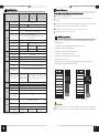
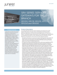
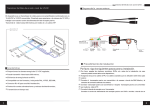
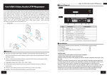
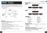
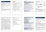
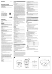
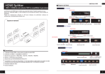
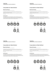
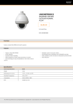
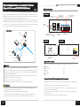
4 Ports Gigabit Ethernet Switch/ 4 Ports
Gigabit Ethernet POE /HPOE Switch
4 Ports Gigabit Ethernet Switch/POE/ HPOE Switch
VerA 1.1
Board diagram
4 ports Gigabit Ethernet switch is an unmanaged Ethernet switch, which provides 2 optical, 2 Ethernet
uplink ports and 4 Gigabit downlink Ethernet ports , wherein 1 optical and 1 Ethernet port are Combo ports .
Front Board
The product could satisfy 32-channel IPC small convergence system application and is widely used in
1~4 ports (yellow
light) indicate PoE
working status
Indicate network
status
security network video surveillance, network engineering and other occasions.
1~4 ports (green light)
indicate network
status
4 ports Gigabit Ethernet PoE/HPOE switch is an unmanaged PoE Ethernet switch, which provides 2 optical,
2 Ethernet uplink ports and 4 Gigabit PoE downlink Ethernet ports , wherein 1 optical and 1 Ethernet ports
are Combo ports. The product supports PoE+/PoE++ high power network Dome. which could be widely
used in security network video surveillance, network engineering and other occasions.
Indicate
power status
Application
r
be
Fi
k er
or iv
w e
et sc
N n
it Tra
ab l
ig ca
G pti
O
Indicate SFP optical
module working
status
SFP
optical port
Uplink
Ethernet port
Fi
be
Left board
With PoE network port
r
Back board
N
VR
10
0m
4P
ort
sG
10
iga
0m
bit
ern
5e
0m
at
10
C
Eth
/6
N
et
PoE IP Camera
et
Po
E/H
PO
w
k
10
or
ES
wi
C
ab
0m
tch
le
PoE Dome Camera
10
PoE Dome Camera
Feature
Standard: IEEE802.3 ,IEEE802.3u ,IEEE802.3ab,IEEE802.3z,IEEE802.3 af/at;
Grounding
terminal
Power input
0m
PoE PTZ camera
Power input
Installation steps
Please check the following items before installation. If any missing, please contact the dealer.
Equipment
1pc
Power adapter
1pc
2pcs
Provide 2 optical and 2 Ethernet uplink ports, wherein 1 optical port and 1 Ethernet port are Combo ports;
Hanger
Provide 4x10/100/1000 Mbps adaptive downlink ports, 1~4 ports of PoE switch support IEEE802.3af/at;
Rack rails
1pc
Support port(Auto MDI/MDIX)function;
User manual
1pc
Standard DC port and green terminal port, support power adapter with different connectors and power;
Redundant power design, support power hot backup;
Fanless wavy metal shell with heat dissipation design ;
Fast installation and easy operation, convenient for wall, din rail and desktop installation.
Caution
1) Please turn off the signal source and the device's power, installation with power on may damage the
device;
2) Use 4 network cables to connect 4 IP cameras and 1~4 RJ45 ports of switch;
1) Transmission distance is related to the connecting cable. We suggest to use standard Cat5e/6
3) Use another network cable (or optical fiber) to connect switch’s uplink port with NVR or computer, etc.;
network cable to get the farthest transmission distance.
4) Connect equipment with power adapter;
2) If using optical port, customer need to purchase SFP module additional;
5) Check if the installation is correct and device is good, make sure all the connection is reliable and
3) The equipment must connect anti-thunder ground, otherwise equipment will greatly reducing
protection level; please use 20th or over wire to connect grounding terminal to the ground.
1
Please follow the following installation steps
power up the system;
6) Make sure every network device has power supply and work normally.
2
4 Ports Gigabit Ethernet Switch/POE/HPOE Switch
4 Ports Gigabit Ethernet Switch/POE/ HPOE Switch
连接接口
Trouble Shooting
连接接口
Specification
连接接口
Please find the following solution when the device doesn't work
4 Ports Gigabit
Ethernet Switch
Item
Voltage range
<6W
Ethernet port
Combo port, SFP optical port:1000Mbps
Other optical port:10/100/1000Mbps
Transmission distance
Ethernet port:100m;
SFP optical port: depend on the optical module transmission
performance
No
PoE power supply
No
PoE power
Protection
level
environment
al
Mechanical
IEEE802.3af, IEEE802.3at agreement
End-span
No
Single port≤30W
4 pairs wire
Single port≤60W
IEEE802.3 ,IEEE802.3u , IEEE802.3ab , IEEE802.3z
If the problem still exist, please contact the factory.
RJ 45 Making Method
EIA/TIA568A or 568B.
1) Shuck off about 2cm long the insulating layer, and bar the 4 pairs UTP cable;
2) Depart the 4 pairs UTP cable and straighten them;
3) Line up the 8 pieces of cables per EIA/TIA 568A or 568B;
4) Cut out 1.5 cm cable wrap and leave the bare wire;
Exchange way
Store and forward
Package data cache
1M
MAC address list
8K
Power indicator
1 indicate power(Red)
Optical port LED
indicator
2 Fiber Link Green lights indicate fiber working status
Uplink Ethernet port
LED indicator
RJ45 port indicates network working status
1~4 ports with
green lights
Downlink Ethernet port
indicate network
LED indicator
status, yellow light
is off
Please replace a failure device with a normal one to check if the device is broken;
Instruments to be used: wire crimper, network tester. Wire sequence of RJ45 plug should conform with
Cat5e/6 standard network cable
PoE agreement
Network standard
Status
indicator
60W, please do not use the PoE device whose consumption is over 30W or 60W;
Consumption
Network port
parameters transmission medium
Network
exchange
specification
The maximum consumption of each PoE port that supply for the PoE equipment can't exceed 30W or
DC48V~57V
DC12V~24V
Please confirm if the installation is correct;
Please confirm if the RJ45 cable order is in accordance with the EIA/TIA568A or 568B industry
standards;
power adapter
Power supply
Power
4 Ports Gigabit
4 Ports Gigabit
Ethernet PoE Switch Ethernet HPoE Switch
5) Plug 8 cables into RJ45 plug, make sure each cable is in each pin;
6) Then use wire crimper to crimp it;
7) Follow the 5 steps above to make the another end, following the same sequence of the first plug;
8) Using network tester to test the cable whether is working.
pin color
pin
color
1
white/green
1
white/orange
2
green
2
orange
3
white/orange
3
white/green
Grade 3, Standard:IEC61000-4-5
4
blue
4
blue
ESD
Grade 3, Standard:IEC61000-4-2
5
white/blue
5
white/blue
Working temperature
-40℃~75℃
6
orange
6
green
Storage temperature
-40℃~85℃
7
white/brown
7
white/brown
Humidity (noncondesing)
8
brown
8
brown
0~95%
Dimension (L×W×H)
110mm×163mm×46mm
Material
Aluminum
Color
Black
Communication port
Weight
510g
1~4 ports with green lights indicate network
status, yellow light indicates PoE
530g
EIA/TIA 568A
EIA/TIA 568B
Caution
530g
When choose RJ-45 make sure if one end is EIA/TIA568A,the other end should also be EIA/TIA568A.
When choose RJ-45 make sure if one end is EIA/TIA568B,the other end should also be EIA/TIA568B.
Products are subject to change without prior notice
3
4