1
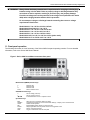
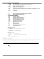
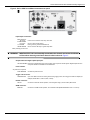
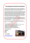
Keithley Instruments, Inc. 28775 Aurora Road Cleveland, Ohio 44139 1-888-KEITHLEY www.keithley.com Keithley Instruments Customer Documentation Series 2400 Safety Supplement 1. Introduction Keithley Instruments Series 2400 SourceMeter® instruments combine a precise, low-noise, highly stable DC power supply with a low-noise, highly repeatable, high-impedance multimeter. 2. Contact information If you have any questions after reading this information, contact your local Keithley Instruments representative or call Keithley Instruments corporate headquarters (toll-free inside the U.S. and Canada only) at 1-888-KEITHLEY (1-888-534-8453), or from outside the U.S. at +1-440-248-0400. For worldwide contact numbers, visit the Keithley Instruments website at www.keithley.com. 3. Package content The following items are included with every Series 2400 order: • • • • • Series 2400 SourceMeter instrument with power line cord Test leads: Model 8605 for Models 2400, 2400-LV, 2401, and 2400-C; Model 1754 for all other Series 2400 models Accessories, as ordered Certificate of calibration CD-ROMs that contain: • PDFs of the Quick Start Guide and User’s Manual, and any additional addenda containing updated product information • Support software (includes Capital Equipment Corporation (CEC) TestPoint™ Data Acquisition Software instrument control library for GPIB and National Instruments (NI™) LabVIEW™ driver for Microsoft® Windows® operating system) 4. Options and accessories Cables and adapters Model 2499-DIGIO adapter: Expands the digital I/O port from four bits to 16 bits. Models 7007-1 and 7007-2 shielded GPIB cables: Connects the Series 2400 to the GPIB bus using shielded cables and connectors, which reduce electromagnetic interference (EMI); Model 7007-1 is 1 m (3.3 ft) long, and Model 7007-2 is 2 m (6.6 ft) long. Models 8501-1 and 8501-2 trigger link cables: Connects the Series 2400 to other instruments with trigger link connectors (for example, a Model 7001 Switch System); Model 8501-1 is 1 m (3.3 ft) long, and Model 8501-2 is 2 m (6.6 ft) long. Model 8502 trigger link adapter: Connects any of the six Series 2400 trigger link lines to instruments that use standard BNC trigger connectors. Model 8503 DIN to BNC trigger cable: Connects Series 2400 trigger link Lines 1 (voltmeter complete) and 2 (external trigger) to instruments that use BNC trigger connectors; 1 m (3.3 ft) long. Model 8505 trigger link adapter cable: The Model 8505 is a male to dual-female Y adapter that connects more than two instruments that have only one trigger link connector on the rear panel; 0.3 m (1 ft) long. PA-1018 Rev. D / March 2013 1 Series 2400 Customer Documentation Safety Supplement Rack-mount kits Model 4288-1 single fixed rack-mount kit: Mounts a single Series 2400 in a standard 19-inch rack. Model 4288-2 side-by-side rack-mount kit: Mounts two instruments (Models 182, 428, 486, 487, 2000, 2001, 2002, 2010, 2015, 2400, 2401, 2410, 2420, 2425, 2430, 2440, 6430, 6517, or 7001) adjacent to each other (side-by-side) in a standard 19-inch rack. Model 4288-3 side-by-side rack-mount kit: Mounts a Series 2400 and a Model 199 adjacent to each other (side-by-side) in a standard 19-inch rack. Model 4288-4 side-by-side rack-mount kit: Mounts a Series 2400 and a 5.25-inch instrument (Models 195A, 196, 220, 224, 230, 263, 595, 614, 617, 705, 740, 775, and so on) adjacent to each other (side-by-side) in a standard 19-inch rack. Model 4288-5 dual fixed rack-mount kit: Mounts a Series 2400 and another 3-inch high instrument (Models 182, 428, 486, 487, 2000, 2010, 2400, 2401, 2410, 2420, 2425, 2430, 6430, or 7001) adjacent to each other (side-by-side) in a standard 19-inch rack. Carrying case Model 1050 padded carrying case: A carrying case for a Series 2400 instrument. Includes handles and a shoulder strap. 5. Electrical rating Table 1: Input supply Input supply All Series 2400 models 100 V AC to 240 V AC, 50/60 Hz, 190 V A Table 2: Source output Models 2400 and 2400-C Model 2400-LV, 2401 Voltage 5 μV to 210 V 5 μV to 20 V Current 50 pA to 1.05 A 50 pA to 1.05 A Table 3: Measuring input Models 2400 and 2400-C Model 2400-LV, 2401 Voltage 1 μV to 211 V, 250 V peak 5 μV to 20 V Current 10 pA to 1.055 A 10 pA to 1.055 A Impedance 100 μΩ to 211 MΩ 100 μΩ to 211 MΩ 6. Assembly, location, and mounting requirements Series 2400 instruments use a heat sink to dissipate heat, and the Models 2410, 2420, 2430, and 2440 also have a cooling fan. The left side of the case is cut out to expose the black, finned heat sink, which gets hot enough to cause burns. You should assume that the heat sink is still hot even when the instrument is turned off (it takes a long time to cool off). 2 PA-1018 Rev. D / March 2013 Series 2400 Customer Documentation Safety Supplement WARNING NEVER touch the heat sink located on the left side of the Series 2400 instrument’s case. This heat sink could be hot enough to cause burns. CAUTION Excessive heat will degrade the Series 2400 instrument’s performance, and could damage the unit. The Series 2400 must be operated in an environment where the ambient temperature does not exceed 50° C (122° F). To prevent damaging heat build-up and ensure specified performance: • Keep the heat sink free of dust, dirt, and contaminates, which will diminish its ability to dissipate heat. • Do not block the bottom cooling vents. NEVER remove the plastic feet and place the Series 2400 directly on a flat surface. NEVER operate the Series 2400 when it is sitting on a surface that conforms to the shape of the unit (such as carpet). This could block the bottom cooling vents. • Do not position any devices adjacent to the Series 2400 that force air (heated or unheated) into or onto its cooling vents or surfaces. This additional airflow could diminish accuracy performance. • When rack mounting the Series 2400, ensure there is adequate airflow around the bottom and sides for proper cooling. Adequate airflow keeps air temperatures within approximately one inch of the Series 2400 surfaces within specified limits under all operating conditions. • Do not rack mount high power-dissipation equipment adjacent to the Series 2400, because excessive heating could occur. The specified ambient temperature must be maintained around the surfaces of the Series 2400 to maintain specified accuracies. • In convection-cooled rack-mounted systems, place the hottest equipment (for example, a power supply) at the top of the rack to ensure proper cooling. Place precision equipment, such as the Series 2400, in the lowest possible position in the rack, where temperatures are coolest. Adding spacer panels below the Series 2400 will ensure adequate air flow. 7. Supply connection and grounding requirements Always use the mains supply cord provided with the instrument, or use a cord with the same (or better) ratings than the one provided. Never use an inadequately rated cord. Before operating an instrument, ensure that the line cord is connected to a properly grounded, appropriately rated power receptacle. Inspect the connecting cables, test leads, and jumpers for possible wear, cracks, or breaks before each use. When installing equipment where access to the main power cord is restricted (such as rack mounting), a separate main input power disconnect device must be provided in close proximity to the equipment and within easy reach of the operator. 8. Ventilation requirements Proper ventilation must be maintained to prevent overheating. The Models 2410, 2420, 2425, 2430, and 2440 use a cooling fan to keep them from overheating; the Models 2400 and 2401 do not have a cooling fan. Refer to the WARNING and CAUTION statements in paragraph 6. Assembly, location, and mounting requirements for details about maintaining proper ventilation of all Series 2400 instruments. 9. Environmental conditions To maintain safety, the following environmental conditions must be maintained: • • • • For indoor use only Altitude up to 2000 m (6,562 ft) Temperature 0° C to 40° C (32° F to 104° F) Maximum relative humidity: 80 percent for temperatures up to 31° C (88° F), decreasing linearly to 50 percent relative humidity at 40° C (104° F) • Mains supply voltage fluctuations not to exceed ±10 percent of the nominal voltage • Maximum mains transient overvoltage category II PA-1018 Rev. D / March 2013 3 Series 2400 Customer Documentation Safety Supplement • Pollution degree: 1 or 2 To maintain accuracy, these additional environmental conditions should be maintained: • An ambient temperature of 18° C to 28° C (65° F to 82° F) • A relative humidity of less than 70 percent (unless otherwise noted) The instrument may be operated at up to 50° C (122° F) if the power output is derated by one watt per channel for each degree Celsius above 30° C (86° F), and at up to 70 percent relative humidity. WARNING Do not connect the Series 2400 terminals to CAT II, CAT III, or CAT IV circuits. The front and rear terminals of the Series 2400 are rated for connection to Installation Category I circuits only. Input/output terminal connections to circuits higher than CAT I can damage the Series 2400 and expose the operator to hazardous voltages. To prevent electric shock and damage to the Series 2400, current from external common-mode voltage sources must be limited using a protective impedance or a fuse. For Models 2400, 2400-C, 2400-LV, and 2401, the input measuring terminals must be protected by a 1 A fuse. 10. Battery charging and discharging WARNING To prevent personal injury or damage to the Series 2400, do not attempt to charge non-rechargeable batteries. You can use your Series 2400 to charge these common battery types: • • • • • Nickel cadmium (NiCD) Nickel metal hydride (NiMH) Lithium ion (Li-ion) Rechargeable alkaline Lead acid If you are using a battery type that is not listed here, please contact your local Keithley Instruments representative or call Keithley Instruments corporate headquarters (toll-free inside the U.S. and Canada only) at 1-888-KEITHLEY (1-888-534-8453), or from outside the U.S. at +1-440-248-0400 to obtain technical assistance. 4 PA-1018 Rev. D / March 2013 Series 2400 Customer Documentation Safety Supplement WARNING Always follow the battery manufacturer’s requirements for charging or discharging batteries using a Series 2400. Failure to properly charge or discharge batteries may cause them to leak or explode, resulting in personal injury and property damage. Provide overvoltage and current protection in the charge circuit (external to the Series 2400) when charging batteries without built-in protection. Do not attempt to charge or discharge batteries exceeding the current or voltage requirements listed below: Model 2400: 21 V at 1.05 A or 210 V at 105 mA Model 2400-LV and 2401: 21 V at 1.05 A Model 2410: 21 V at 1.05 A or 1100 V at 21 mA Model 2420: 21 V at 3.15 A or 63 V at 1.05 A Model 2425: 21 V at 3.15 A or 105 V at 1.05 A Model 2430: 105 V at 1.05 A or 105 V at 10.5 A (pulse mode) Model 2440: 10.5 V at 5.25 A or 42 V at 1.05 A 11. Front panel operation The following information is a brief summary of the Series 2400 front-panel operating controls. For more detailed information, refer to the Series 2400 User’s Manual. Figure 1: Series 2400 SourceMeter instrument front panel Measurement (MEAS) function keys: V I Ω FCTN Measure volts Measure amps Measure ohms Perform math functions SOURCE function keys: V I and Source voltage (V-Source) Source current (I-Source) Increase/decrease source or compliance value Operation keys: EDIT TOGGLE LOCAL REL FILTER LIMIT TRIG PA-1018 Rev. D / March 2013 Select source or compliance reading for editing Toggle display positions of source and measure readings, or display V and I measurements Cancel remote operation Enable/disable relative reading on present function Display digital filter status for present function and toggle filter on/off Perform configured limit tests Trigger a measurement from the front panel 5 Series 2400 Customer Documentation Safety Supplement SWEEP and DIGITS SPEED STORE RECALL CONFIG MENU EXIT ENTER Start configured sweep Move through parameter values or selections within functions and operations Change number of digits of display resolution Change measurement speed by selecting accuracy or specifying NPLC Set buffer size and enable reading storage Display stored readings and timestamp Press CONFIG and then press the appropriate key to configure the function or operation Access and configure Main Menu selections; when entering numeric data, use to clear reading to minimum absolute value Cancels selection; use to back out of menu structures Accepts selection RANGE keys: AUTO Moves to next higher range, increments digit, moves to next selection Moves to next lower range, decrements digit, moves to previous selection Enables or disables measurement auto range Annunciators (display indicators): EDIT ERR REM TALK LSTN SRQ REAR REL FILT MATH 4W AUTO ARM TRIG * Instrument is in edit mode Questionable reading, invalid calibration step Instrument is in GPIB remote mode Instrument is addressed to talk over GPIB Instrument is addressed to listen over GPIB Service request over GPIB Rear input/output connectors selected Relative measure reading displayed Digital filter enabled Math function enabled Remote sensing enabled Autoranging enabled Source-measure operations are being performed External trigger source selected Reading is being stored Input/output connectors: INPUT/OUTPUT HI and LO Use to source-measure volts, amps, and ohms 4-WIRE SENSE HI and LO Use for 4-wire remote sensing Input/output controls: ON/OFF FRONT/REAR Turns the source on or off Selects front- or rear-panel input/output connections Handle: Pull out and rotate to desired position 11. Rear panel overview The rear panel of the Model 2400 SourceMeter instrument is shown in Figure 2 (the Models 2410, 2420, 2425, 2430, and 2440 are similar). Review the following abbreviated information before operating the instrument. NOTE 6 Models 2420, 2425, 2430, and 2440 are not UL listed. PA-1018 Rev. D / March 2013 Series 2400 Customer Documentation Safety Supplement Figure 2: Series 2400 SourceMeter instrument rear panel Input/output connectors: INPUT/OUTPUT HI and LO 4-WIRE SENSE HI and LO V, Ω GUARD GUARD SENSE Use to source-measure volts, amps, and ohms Use for 4-wire remote sensing Driven guard for guarded measurements Use to correct for IR drops in guard output lead Earth (chassis) ground screw WARNING INPUT/OUTPUT LO is not internally connected to the chassis and cannot be allowed to float above chassis ground more than the values shown in Figure 3. Output enable and digital input/output port: OUTPUT ENABLE Connector for digital output lines, output enable, and component handler signals. Digital Output lines and component handler not available on the Model 2401. Power module: AC power line receptacle FUSE DRAWER Contains the power line fuse Trigger link connector: TRIGGER LINK 8-pin micro-DIN connector for sending and receiving trigger pulses; use a trigger link cable or adapter (for example, Models 8501-1, 8501-2, 8502, or 8504) RS-232 connector: RS-232 Connector for RS-232 remote operation; use a straight-through (not null modem) DB-9 cable GPIB connector: IEEE-488 PA-1018 Rev. D / March 2013 Connector for GPIB remote operation; use a shielded cable (Model INTERFACE 7007-1 or 7007-2) 7 Series 2400 Customer Documentation Safety Supplement Figure 3: Terminal voltage differentials WARNING: NO INTERNAL OPERATO 5V PK HI 250V PEAK 250V PEAK 5V PEAK WARNING: NO INTERNAL OPERAT 5V PK HI V, W GUARD 5V PEAK 50V PEAK V, W GUARD 5V PEAK 50V PEAK 5V PEAK GUARD SENSE 4-WIRE SENSE LO ! INPUT/ OUTPUT GUARD SENSE 4-WIRE SENSE CAT I 250V PEAK LO ! Model 2400, 2400-C INPUT/ OUTPUT 250V PEAK Model 2401 WARNING: NO INTERNAL OPERATO 5V PK HI 1100V PEAK 5V PEAK 1100V PEAK WARNING: NO INTERNAL OPERAT V, W GUARD 5V PEAK 5V PK HI 75V PEAK 5V PEAK 75V PEAK V, W GUARD 5V PEAK GUARD SENSE 4-WIRE SENSE LO ! INPUT/ OUTPUT GUARD SENSE CAT I 250V PEAK 4-WIRE SENSE Model 2410, 2410-C LO INPUT/ OUTPUT Model 2420, 2420-C WARNING: NO INTERNAL OPERAT 5V PK HI 125V PEAK 5V PEAK 125V PEAK 250V PEAK WARNING: NO INTERNAL OPERAT 5V PK HI V, W GUARD 5V PEAK 52V PEAK 5V PEAK 42V PEAK 4-WIRE SENSE INPUT/ OUTPUT 250V PEAK Model 2425, 2425-C, 2430, 2430-C 8 5V PEAK GUARD SENSE GUARD SENSE LO V, W GUARD 4-WIRE SENSE LO INPUT/ OUTPUT 40V PEAK Model 2440, 2440-C PA-1018 Rev. D / March 2013