1
Number 806
Application Note
Series
Production Testing of Thermistors Using
the Model 2400 SourceMeter® Instrument
Introduction
Test Description
Thermistors are devices that exhibit a change in resistance
with a change in temperature. The resistance of an NTC (negative
temperature coefficient) thermistor decreases with an increase in
temperature, whereas the resistance of a PTC (positive temperature coefficient) thermistor increases with an increase in temperature. Thermistors have many applications, including their use as
temperature sensors, resettable fuses, power indicators, and
current limiters.
The DC resistance value of a thermistor is measured at one
or more specific temperatures, typically 25°C. To get accurate
measurements, the test method must ensure self-heating of the
thermistor is minimized. This can be done by using the lowest
possible DC or pulsed test current. Testing the thermistors in an
oil bath also reduces heating effects and ensures temperature
stability. In some cases, however, the thermistors may be tested in
air, in which case, lower current or pulsed current is used. In
either case, the oil or air temperatures are typically measured
because measuring and compensating for the temperature is
usually easier than trying to control it. A reference thermistor,
which has a similar composition to the thermistors being tested, is
often used to make the temperature compensation measurement.
Once the temperature is known, the control software can correct
for the actual resistance measurement of the thermistor. The
resistance value is compared to a standard value, then the
thermistor is either sorted with an automatic handling machine
and placed in the proper bin or reground to tolerance.
Due to the wide variety of applications for thermistors, the
specific production tests performed on these devices often depend
on the application. One common production test, regardless of the
application, is resistance versus temperature. The range of
resistance of a thermistor may vary from <1Ω to as high as 1MΩ.
In most cases, however, the resistance is in the kilo-ohm range.
While digital multimeters are often used to measure the resistance, these instruments do not usually allow programming the
magnitude and duration of the test current. To keep the test
current low when using a DMM, the resistance measurement
must often be made on a higher range, which decreases sensitivity. However, the Model 2400 SourceMeter instrument measures
a wide range of resistance and has an adjustable test current. This
instrument measures resistance directly by using a separate
current source and voltmeter. Even though it combines both a
source and measuring instrument in one unit, it is the same size as
a half-rack DMM and is just as easy to use.
This application note describes how to configure a thermistor production test system using the Model 2400 SourceMeter
instrument. A short program that’s included configures the
instrument to output a single short current pulse and measure the
resistance. Another program provided measures the resistance of
an external temperature device and then calculates the temperature. In some production applications, the temperature reference
and the thermistors need to be switched to only one SourceMeter
instrument. For these cases, a test configuration that includes
programmable switching instruments is provided.
Test Procedures
Using the Model 2400 to Measure the Resistance of a
Thermistor
Depending on the magnitude of resistance being measured,
either a two-wire or four-wire method is used. The 4-wire method
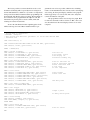
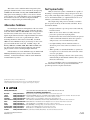
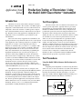
prevents any lead resistance from being added into the measurement. For measurements in the kilo-ohm ranges, a two-wire
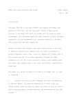
approach is usually sufficient. Figure 1 illustrates making a twowire connection from the SourceMeter to a thermistor.
In/Out
HI
Model 2400
Current
Source
RT
Voltmeter
In/Out
LO
Figure 1. Using the Model 2400 to measure resistance of a thermistor
The lowest possible test current should be used to avoid
thermistor self-heating. This is especially true for testing in air
and for NTC thermistors, which are very sensitive to temperature
changes. The SourceMeter instrument allows programming both
the magnitude and duration of the test current. The magnitude of
the test current can be programmed from ±50pA to ±1A. The
instrument can generate pulses as short as ≈2ms, while still
ensuring an accurate measurement.
To meet the time limitation when outputting pulses in the
millisecond range, the SourceMeter instrument must be pro-
grammed to run as fast as possible, which involves disabling
features of the instrument that slow it down, such as autoranging,
auto zeroing, the front panel display, and filters. The programmable trigger delay is set to 0 seconds. The source delay time
controls the duration of the pulse.
The program listed below was developed to output 10µA
for 5ms into a thermistor with a resistance of 10kΩ. One resistance measurement is taken and displayed on the screen of the
computer.
' Program Name is 2400res.bas.
'$INCLUDE: 'ieeeqb.bi'
' This program uses Microsoft QuickBasic 4.5 and the KPC-488.2AT IEEE
' Interface Card
CALL initialize(21, 0)
CALL transmit("UNT UNL MTA LISTEN 24 SDC UNL UNT", gpib.status%)
CALL send(24, "*RST", gpib.status%)
DATA$ = SPACE$(800)
REM*****global paramters
CALL send(24, ":SYST:AZERO 0", gpib.status%)
CALL send(24, ":SYST:RSEN 0", gpib.status%)
CALL send(24, ":DISP:ENABLE OFF", gpib.status%)
CALL send(24, ":FORM:ELEM RES", gpib.status%)
'auto zero off
'local sense, 2-wire
'turn display off
'resistance reading only
REM*****set measure/compliance
CALL send(24, ":SENS:FUNC:OFF:ALL", gpib.status%)
CALL send(24, ":SENS:FUNC 'RES'", gpib.status%)
CALL send(24, ":SENS:RES:MODE MAN", gpib.status%)
CALL send(24, ":VOLT:RANG 2;NPLC 0.01", gpib.status%)
CALL send(24, ":VOLT:PROT 20", gpib.status%)
'turn all functions off
'turn on resistance function
'manual resistance mode
'2 volt range
'20 volt compliance
REM******set source
CALL send(24, ":SOURCE:FUNC:MODE CURR", gpib.status%)
CALL send(24, ":SOURCE:CLEAR:AUTO ON", gpib.status%)
CALL send(24, ":SOURCE:CURR:RANG 100E-6", gpib.status%)
CALL send(24, ":SOURCE:CURR 10E-6", gpib.status%)
CALL send(24, ":SOURCE:CURR:MODE FIXED", gpib.status%)
CALL send(24, ":SOURCE:DELAY .004", gpib.status%)
'souce current
'source clear auto
'4ms delay time
REM*****set output to ZERO mode
CALL send(24, ":OUTPUT:SMODE ZERO", gpib.status%)
REM*****set trigger
CALL send(24, "ARM:COUNT 1", gpib.status%)
CALL send(24, "TRIG:COUN 1", gpib.status%)
CALL send(24, "TRIG:SOURCE IMM", gpib.status%)
CALL send(24, "TRIG:DELAY 0", gpib.status%)
'output 1 pulse
'no delay before pulse
REM*****take reading
CALL send(24, ":READ?", gpib.status%)
CALL enter(DATA$, lenght%, 24, gpib.status%)
PRINT DATA$
REM*****turn output OFF
CALL send(24, ":SOURCE:CLEAR:AUTO OFF", gpib.status%)
CALL send(24, ":OUTP OFF", gpib.status%)
END
'turn off source
The duration of the test current is controlled using the
:SOURCE:DELAY command. In the program listing, note that
the source delay was programmed for 4ms, even though the
actual pulse is about 5ms in length. Depending on the setup of the
2400, there is roughly 1ms of overhead time when both sourcing
a current and taking a voltage measurement. A discussion for
calculating the source-delay-measure timing cycle can be found
in the Model 2400 User’s Manual.
Using the Model 2400 to Measure Temperature
It’s also necessary to measure the temperature of the air or
oil in which the thermistors are tested. This temperature measurement is often made with a thermistor that has a similar composition to the thermistors being tested. This similarity is important in
order to ensure that the reference thermistor and the thermistors
under test will have the same temperature time constant. However, in some cases, a more accurate temperature sensor, such as
an RTD, may be used. The Model 2400 has a dual-channel input
'Program name is 2400temp.bas
'$INCLUDE: 'ieeeqb.bi'
'This program uses Microsoft Quickbasic 4.5 and the KPC-488.2AT IEEE Interface Card
CALL initialize(21, 0)
CALL transmit("UNT UNL MTA LISTEN 24 SDC UNL UNT", status%)
CALL send(24, "*RST", status%)
REM*****set function:
CALL send(24, ":SENS:FUNC 'RES'", status%)
CALL send(24, ":RES:MODE MAN", status%)
CALL send(24, ":RES:RANG 10E3;NPLC 1.0", status%)
'measure resistance
'manual mode
REM******set source:
CALL send(24, ":SOURCE:FUNC:MODE CURR", status%)
CALL send(24, ":SOURCE:CURR:RANG 10E-6", status%)
CALL send(24, ":SOURCE:CURR 1E-6", status%)
CALL send(24, ":SOURCE:CURR:MODE FIXED", status%)
CALL send(24, ":SOURCE:DELAY 0", status%)
REM*****global paramters
CALL send(24, ":SYST:AZERO 0", status%)
CALL send(24, ":SYST:RSEN 0", status%)
REM*******set
CALL send(24,
CALL send(24,
CALL send(24,
CALL send(24,
CALL send(24,
CALL send(24,
'auto zero off
'remote sense off
up math expression for temperature conversion
":CALC:MATH:DEL:ALL", status%)
":CALC:MATH:EXPR:NAME 'TEMP'", status%)
":CALC:MATH:EXPR ((res - 4593.39)/(-32.402))", status%)
":CALC:MATH:NAME 'TEMP'", status%)
":CALC:MATH:UNITS 'C'", status%)
":CALC:STATE ON", status%)
REM*****set trigger:
CALL send(24, "ARM:COUNT 1", status%)
CALL send(24, "TRIG:COUNT 1", status%)
CALL send(24, "TRIG:SOURCE IMM", status%)
CALL send(24, "TRIG:DELAY 0", status%)
'trigger once
CALL send(24, "OUTPUT ON", status%)
'turn output ON
REM*****get temperature reading:
CALL send(24, ":INIT", status%)
CALL send(24, ":CALC:DATA?", status%)
A$ = SPACE$(80)
CALL enter(A$, length%, 24, status%)
PRINT USING "##.##C"; VAL(LEFT$(A$, length%))
'turn output OFF
CALL send(24, ":OUTP OFF", status%)
END
(programmable front/rear switching), so the reference temperature can be measured at the rear terminals and the resistance of
the unknown thermistor can be measured at the front terminals. In
this way, it’s possible to take a temperature compensation
measurement automatically without the need for a second
instrument. If timing is critical, keep in mind that the sum of both
the switching and settling times can be in the tens of milliseconds.
Model 7001
Mainframe
with one
Model 7011
Scanner Card
Reference
RT
#1
RT
#2
RT
#39
Ch. 2
Ch. 3
When the 2400 is switched from one input to the other, the
output is automatically turned off, ensuring cold switching. The
relay used to switch between front and rear inputs (Keithley Part
No. RL-163) has a mechanical life expectancy of 108 operations.
If the contact life of the RL-163 relay is not long enough, then a
separate scanner system can be used with the SourceMeter
instrument to switch the input, either to the thermistor under test
or the temperature sensing element. This is discussed further in
the section titled, “Switching Multiple Thermistors.”
To illustrate measuring temperature using the SourceMeter
instrument, a thermi-linear component consisting of both a
thermistor composite and a resistor set can be used as a temperature sensing element. This particular device linearly relates its
resistance to a temperature over a specific temperature range. The
program for the SourceMeter instrument on the previous page
automatically converts the resistance of the device (as expressed
in ohms) to a temperature measurement (in degrees Celsius) by
using the instrument’s built-in math capability.
RT
Ch. 1
To other
channels
Ch. 40
Output
In/Out HI
Model 2400
In/Out LO
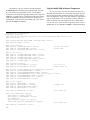
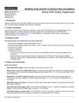
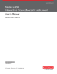
Figure 2. Switching multiple thermistors to Model 2400 using 2-wire method
Reference
Model 7001
Mainframe
with 7011
Card #1
RT
Ch. 41
Ch. 1
RT
#1
Ch. 42
Ch. 2
Example Programs
RT
Ch. 43
To other
channels
RT
Switching Multiple Thermistors
Some applications require switching both the temperature
sensor and the thermistors to a single SourceMeter instrument.
Figure 2 shows the input/output of the instrument being switched
to either one reference thermistor or to any of the 39 thermistors
of unknown value.
In this switching example, a two-wire technique is used.
The scanning is accomplished using one Model 7001 Scanner
Mainframe and one Model 7011 40-Channel Switch Card. To
measure the reference thermistor, Channel 1 is closed and the
resistance is measured. Open Channel 1, then close Channel 2 to
measure the resistance of the first thermistor, RT #1. This process
is repeated for all the thermistors.
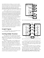
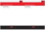
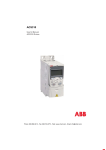
Figure 3 shows a scanner system using a four-wire technique. For scanning thermistors with lower resistances (<100Ω),
a four-wire technique is used to prevent the lead resistance from
being added into the measurement. Note that two 2-pole relays
are used to connect each thermistor to the instrument.
#2
Ch. 3
To obtain a digital file of either of the Example Programs
listed, access Keithley’s World Wide Web site.
7011
Card #2
#39
Ch. 50
Ch. 40
Output
Output
In/Out LO
In/Out HI
Model 2400
Sense HI
Sense LO
Figure 3. Switching multipple thermistors to Model 2400 using 4-wire method
To measure the resistance of the reference thermistor, close
Channels 1 and 41, apply the specified current, and measure the
resistance. Open Channels 1 and 41, then close Channels 2 and 42
to begin testing the first thermistor, RT #1. Repeat this procedure
for all the thermistors.
The actual number of thermistors may vary, depending on
the system. Switching systems can be configured for any number
of thermistors and for various electrical specifications. When
used with the appropriate scanner cards, each Keithley Model
7002 Scanner Mainframe can switch up to 400 thermistors using
a two-pole method or up to 200 thermistors using a four-pole
method. Multiple mainframes may be used for larger systems.
Test System Configuration
In/Out
HI
Model 2400
Component Handler
Digital I/O
PC
IEEE-488
2400
SourceMeter
Instrument
Test Leads
Mechanical
Connection
Current
Source
DUT
In/Out
LO
Test Fixture
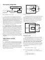
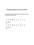
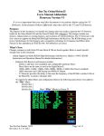
Figure 4. Thermistor production test system
A block diagram of a Model 2400-based production test
system for thermistors is shown in Figure 4. The thermistor is
placed in a temperature-controlled test fixture with connections to
the instrument. When triggered, the instrument outputs a current
and measures the voltage drop across the thermistor, then
automatically calculates the resistance. The instrument compares
this resistance measurement to a pre-specified limit, then sends a
signal via the digital I/O port to the component handler, which
assigns the thermistor to the appropriate bin.
As Figure 4 illustrates, the Model 2400 has both an IEEE488 output and a digital I/O port. The digital I/O port can send
signals directly to and receive signals from an automatic handler
machine. Up to five limit values (one compliance, two high and
two low values) can be programmed into the instrument. The limit
values will determine the Pass/Fail and High/Low status of
subsequent measurements. Once a measurement is made and the
tolerance is determined, the digital I/O port sends a TTL level
signal to the automatic handling machine to route the thermistor to
the appropriate bin. The SourceMeter instrument has four digital
output lines that can be used to set up bit patterns to produce TTL
level signals.
Typical Sources of Error
Lead Resistance
A common source of resistance measurement error is the
series resistance of the test leads running from the SourceMeter
instrument to the thermistor. This series resistance is added into
the measurement when making a two-wire connection (See
Figure 5). The effect of lead resistance is particularly detrimental
when long connecting cables and high currents are used, because
the voltage drop across the lead resistance becomes significant
compared to the measured voltage.
RT
Voltmeter
Figure 5. Two-wire technique
To eliminate this problem, use the four-wire remote sensing
method rather than the two-wire technique. With the four-wire
method (Figure 6), a current is forced through the thermistor
using one pair of leads and the voltage across the thermistor is
measured through a second set of leads. As a result, only the
voltage drop across the thermistor is measured.
Model 2400
In/Out HI
Sense HI
Current
Source
RT
Voltmeter
Sense LO
In/Out LO
Figure 6. Four-wire technique
Thermoelectric EMFs
Thermoelectric EMFs may cause measurement problems,
especially when testing the thermistors in air. One way to avoid
these thermally generated voltages is to use the instrument’s
offset compensated ohms mode. This mode works by first taking
a measurement with the source current on, then taking another
with the source current off. The second measurement is then
subtracted from the first measurement, canceling out any voltage
offsets. The corrected measurement is automatically determined
by using the two point measurement method and is expressed
mathematically as:
V2 – V1
Offset Compensated Ohms = ______
I2 – I1
where: I1 is the source current set to a specified level.
I2 is the source current set to zero (it could be set to any
level).
V1 is the voltage measured at I1.
V2 is the voltage measured at I2.
This feature can be enabled from the front panel by first
placing the instrument in the source current mode, then pressing
CONFIG and then FCTN. Selecting OFF-COMP-OHMS will
bring up the menu, making it possible to select the two desired
source currents (one of which should be zero). If programming
the instrument via the bus, the Offset Compensated Ohms
function is configured using the CALC1 Subsystem.
Test System Safety
Many electrical test systems or instruments are capable of
measuring or sourcing hazardous voltage and power levels. It is
also possible, under single fault conditions (e.g., a programming
error or an instrument failure), to output hazardous levels even
when the system indicates no hazard is present.
These high voltage and power levels make it essential to
protect operators from any of these hazards at all times. Protection methods include:
Alternative Solutions
If controlling the duration and magnitude of the test current
is unimportant, then a DMM can be used to make these measurements. The Models 2001 and 2002 DMMs offer two high and two
low limit values, which can be tied to the status of any of four
digital outputs. When used with a component handler, this allows
these DMMs to be used to sort or grade thermistors. When
measuring thermistors with values less than 100Ω, the Model
2010 Low-Noise Multimeter may be used because it offers a low
power measurement mode on the 10Ω and 100Ω ranges. All
Keithley 2000 Series DMMs (2000, 2001, 2002 and 2010) offer
two and four-wire ohms measurement functions and optional
plug-in scanner cards for switching multiple thermistors.
If the thermistors are in the milliohm range, the Model 2750
Multimeter/Switch System provides resistance measurements
with 10µΩ resolution and includes a built-in switch mainframe
for multi-channel operation.
• Design test fixtures to prevent operator contact with any
hazardous circuit.
• Make sure the device under test is fully enclosed to
protect the operator from any flying debris.
• Double insulate all electrical connections that an operator
could touch. Double insulation ensures the operator is
still protected, even if one insulation layer fails.
• Use high reliability, fail-safe interlock switches to
disconnect power sources when a test fixture cover is
opened.
• Where possible, use automated handlers so operators do
not require access to the inside of the test fixture or have
a need to open guards.
• Provide proper training to all users of the system so they
understand all potential hazards and know how to protect
themselves from injury.
It is the responsibility of the test system designers, integrators, and installers to make sure operator and maintenance
personnel protection is in place and effective.
Specifications are subject to change without notice.
All Keithley trademarks and trade names are the property of Keithley Instruments, Inc.
All other trademarks and trade names are the property of their respective companies.
Keithley Instruments, Inc.
28775 Aurora Road • Cleveland, Ohio 44139 • 440-248-0400 • Fax: 440-248-6168
1-888-KEITHLEY (534-8453) www.keithley.com
BELGIUM:
Keithley Instruments B.V.
CHINA:
Keithley Instruments China
FRANCE:
Keithley Instruments Sarl
GERMANY:
Keithley Instruments GmbH
GREAT BRITAIN: Keithley Instruments Ltd.
INDIA:
Keithley Instruments GmbH
ITALY:
Keithley Instruments s.r.l.
KOREA:
Keithley Instruments Korea
NETHERLANDS: Keithley Instruments B.V.
SWITZERLAND: Keithley Instruments SA
TAIWAN:
Keithley Instruments Taiwan
Bergensesteenweg 709 • B-1600 Sint-Pieters-Leeuw • 02-363 00 40 • Fax: 02/363 00 64
Yuan Chen Xin Building, Room 705 • 12 Yumin Road, Dewai, Madian • Beijing 100029 • 8610-6202-2886 • Fax: 8610-6202-2892
3, allée des Garays • 91127 Palaiseau Cédex • 01-64 53 20 20 • Fax: 01-60 11 77 26
Landsberger Strasse 65 • 82110 Germering • 089/84 93 07-40 • Fax: 089/84 93 07-34
Unit 2 Commerce Park, Brunel Road • Theale • Reading • Berkshire RG7 4AB • 0118 929 7500 • Fax: 0118 929 7519
Flat 2B, Willocrissa • 14, Rest House Crescent • Bangalore 560 001 • 91-80-509-1320/21 • Fax: 91-80-509-1322
Viale San Gimignano, 38 • 20146 Milano • 02-48 39 16 01 • Fax: 02-48 30 22 74
2FL., URI Building • 2-14 Yangjae-Dong • Seocho-Gu, Seoul 137-130 • 82-2-574-7778 • Fax: 82-2-574-7838
Postbus 559 • 4200 AN Gorinchem • 0183-635333 • Fax: 0183-630821
Kriesbachstrasse 4 • 8600 Dübendorf • 01-821 94 44 • Fax: 01-820 30 81
1FL., 85 Po Ai Street • Hsinchu, Taiwan, R.O.C. • 886-3-572-9077• Fax: 886-3-572-9031
© Copyright 2001 Keithley Instruments, Inc.
Printed in the U.S.A.
No. 1838
7012KDCI