1
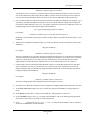
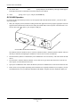
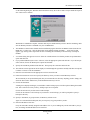
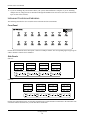
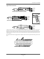
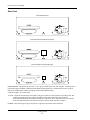
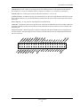
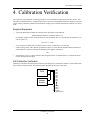
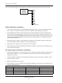
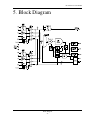
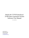
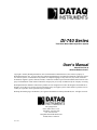
The way PC-based instrumentation should be
DI-740 Series
Transducer-Based Data Acquisition System
User'sManual
Manual
Revision A
Software Release Level 1
Copyright © 2006 by DATAQ Instruments, Inc. The Information contained herein is the exclusive property of
DATAQ Instruments, Inc., except as otherwise indicated and shall not be reproduced, transmitted, transcribed, stored
in a retrieval system, or translated into any human or computer language, in any form or by any means, electronic,
mechanical, magnetic, optical, chemical, manual, or otherwise without expressed written authorization from the company. The distribution of this material outside the company may occur only as authorized by the company in writing.
DATAQ Instruments' hardware and software products are not designed to be used in the diagnosis and treatment of
humans, nor are they to be used as critical components in any life-support systems whose failure to perform can reasonably be expected to cause significant injury to humans.
DATAQ, the DATAQ logo, and WINDAQ are registered trademarks of DATAQ Instruments, Inc. All rights reserved.
241 Springside Dr.
Akron, Ohio 44333 U.S.A.
Telephone: 330-668-1444
Fax: 330-666-5434
Designed and manufactured in the
United States of America
M-101028
Warranty and Service Policy
Product Warranty
DATAQ Instruments, Inc. warrants that this hardware will be free from defects in materials and workmanship under
normal use and service for a period of one year from the date of shipment. DATAQ Instruments' obligations under
this warranty shall not arise until the defective material is shipped freight prepaid to DATAQ Instruments. The only
responsibility of DATAQ Instruments under this warranty is to repair or replace, at its discretion and on a free of
charge basis, the defective material.
This warranty does not extend to products that have been repaired or altered by persons other than DATAQ Instruments employees, or products that have been subjected to misuse, neglect, improper installation, or accident.
DATAQ Instruments shall have no liability for incidental or consequential damages of any kind arising out of the sale,
installation, or use of its products.
Service Policy
1.
All products returned to DATAQ Instruments for service, regardless of warranty status, must be on a freight-prepaid basis.
2.
DATAQ Instruments will repair or replace any defective product within 5 days of its receipt.
3.
For in-warranty repairs, DATAQ Instruments will return repaired items to the buyer freight prepaid. Out of warranty repairs will be returned with freight prepaid and added to the service invoice.
DI-740 Series User Manual
Table of Contents
Warranty and Service Policy ................................................................................................................
1. Introduction ........................................................................................................................................
Features ..............................................................................................................................................
Analog Input ......................................................................................................................................
Analog Output ...................................................................................................................................
2. Specifications ......................................................................................................................................
Signal Connections ............................................................................................................................
Interface Characteristics ....................................................................................................................
Analog Inputs ....................................................................................................................................
Analog Outputs ..................................................................................................................................
Excitation Output ...............................................................................................................................
Shunt Cal ...........................................................................................................................................
Timing Input/Output ..........................................................................................................................
Scan Lists ...........................................................................................................................................
Triggering ..........................................................................................................................................
On-board DSP ....................................................................................................................................
Physical/Environmental .....................................................................................................................
Power Supply Voltage and Power Consumption ..............................................................................
3. Getting Started ...................................................................................................................................
Unpacking ..........................................................................................................................................
Applying Power .................................................................................................................................
Connecting the DI-740 Series Instrument to your Computer ............................................................
Parallel (Printer) Port Operation .................................................................................................
DI-740-EN Operation .................................................................................................................
TCP/IP Manager ...................................................................................................................
Status ..............................................................................................................................
Description .....................................................................................................................
IP Address ......................................................................................................................
MAC Address ................................................................................................................
Start WinDaq .................................................................................................................
Advanced Options: .........................................................................................................
File Name .......................................................................................................................
File Size .........................................................................................................................
Setup File Name .............................................................................................................
Auto Start .......................................................................................................................
Slave Mode ....................................................................................................................
Change IP Address with TCP/IP Manager ....................................................................
Change Network ............................................................................................................
TCP/IP Reference Information for Non -A Instruments ......................................................
Assigning IP Addresses for Non -A Instruments .................................................................
DI-740-USB Operation ...............................................................................................................
Instrument Controls and Indicators ...................................................................................................
Front Panel ..................................................................................................................................
Side Panels ..................................................................................................................................
Typical Field Connections ....................................................................................................
Table of Contents
v
iii
1
1
1
1
3
3
3
3
3
4
4
4
4
4
4
4
5
7
7
7
8
8
9
10
10
11
11
11
11
12
12
12
13
13
13
13
14
14
15
18
20
20
20
21
DI-740 Series User Manual
Rear Panel ...................................................................................................................................
4. Calibration Verification .....................................................................................................................
Required Equipment ..........................................................................................................................
A/D Calibration Verification .............................................................................................................
Offset Calibration Verification ..........................................................................................................
Full Scale (Span) Calibration Verification ........................................................................................
5. Block Diagram ....................................................................................................................................
Table of Contents
vi
22
25
25
25
26
26
27
DI-740 Series User Manual
1. Introduction
Congratulations on your purchase of a DI-740 Series data acquisition instrument. These instruments permit data
acquisition on IBM personal computers and compatibles from either Windows or the DOS programming environments. This manual describes how to connect and use all of the instruments in the DI-740 Series. This manual is written with the assumption that you have a general understanding of data acquisition, digital I/O and DSP operations,
and that you possess enough proficiency in software to write your own application and/or diagnostic programs.
Features
The DI-740 Series provides the following features:
•
All instruments connect to the parallel port of any desktop, transportable, notebook or laptop PC-compatible
computer. Most communicate through the PC's parallel port in standard, bi-directional or EPP mode. Ethernet
and USB models can only communicate in bi-directional or EPP modes. Models DI-740-EN and DI-740-USB
add optional Ethernet and USB communication modes respectively.
•
Per channel software-configurable settings:
Input gain.
Sample rate.
Intelligent Oversampling Modes: Signal averaging, maximum value, minimum value and last point
DI-740 Series: 16 transducer inputs and 16 general-purpose inputs.
(General purpose inputs: those connected directly to a multiplexer. Each channel can be configured for single-ended or differential operation on a channel-by-channel basis. General-purpose inputs can have gain factors of 1, 2, 4 or 8 applied on a channel-by-channel basis.)
•
Flexible power requirements. All instruments operate from any standard 60Hz, 120V AC wall outlet with the
supplied power adapter. Or, power the instruments from any +9 to +36 volt DC source, such as a car battery.
•
200KHz burst sampling rate for parallel port module
200KHz burst sampling rate for USB
50KHz burst sampling rate for EN
•
Analog-to-Digital converters:
16-bit A/D converters for high-resolution measurement accuracy (14 bits maximum resolution using
WINDAQ software).
•
240-entry input list allows you to scan any sequence of input channels at any available gain. The 240-entry input
list also allows you to average 32,768 consecutive readings per channel for low-noise output signals.
•
240 counters are assigned to the input list allowing each channel to be programmed for a different sample rate.
•
Supports analog pre- and post-triggering of data acquisition based on the level and slope of a specified channel.
The following provides a brief overview of the major subsystems of the DI-740 Series.
Analog Input
The DI-740 Series is a specialized unit designed specifically for transducer-based measurements. It features 16 channels where each channel provides its own isolated power supply for transducer excitation, thus eliminating the need
for separate power supplies when making measurements using transducers with built-in amplifiers. Each DI-740
input channel features software programmable input measurement ranges of ±1.25 to ±10 V full scale.
Analog Output
DI-740 instruments has one 12-bit D/A converter for outputting analog data.
DI-740 Series instruments feature a software-programmable output range of ±10V.
Introduction
1
DI-740 Series User Manual
DI-740 Series instruments feature an on board 16-entry output counter list that allows you to write analog or digital
output at the maximum conversion rate of the instrument.
Analog output is not available in DI-740 Ethernet and USB modules while Analog Input is being used.
Introduction
2
DI-740 Series User Manual
2. Specifications
Signal Connections
Signal connections are made directly to the removable terminal strips on DI-740 Series instruments.
Interface Characteristics
Compatible computer architecture:
Any PC architecture. Connects to computer via the parallel (or printer)
port. Supports standard, bi-directional, or EPP communication modes
(Ethernet and USB models only support bi-directional and EPP communication modes). Optional communication interfaces include Ethernet
and Universal Serial Bus (USB).
Analog Inputs
Number of input channels:
16 single-ended transducer inputs, 16 general purpose inputs (16se/8di)
Converter resolution:
16-bit
Common mode rejection ratio:
80 dB minimum @ Av=1 (general purpose channels)
Accuracy:
±0.25% of full-scale range ±100µv
Crosstalk:
-75 dB @ 100kHz and 100 unbalance
Sample throughput rate (max samples/second; software selectable per channel):
Printer port Standard port: 40,000
Bi-directional port: 80,000
EPP: 200,000
USB 200,000 samples/second max
Ethernet 50,000 samples/second max
Maximum analog measurement range
(general purpose channels; software selectable per channel)
±10V full scale at a gain of 1
±5V full scale at a gain of 2
±2.5V full scale at a gain of 4
±1.25V full scale at a gain of 8
Maximum Input without Damage (either ±30VDC or Peak AC
input to ground)
Gain error:
1 bit max @ 1kHz sample rate
Input offset voltage:
1 bit max @ 1kHz sample rate
Input settling time:
4µs to 0.01% at all gains
Input impedance:
1 MΩ resistor tied to GND on the input channel
Analog Outputs
Number of channels:
One analog output
Resolution:
12-bit; 1 part in 4,096 @ 250kHz
Output voltage range:
±10V full scale
Output impedance:
10 MΩ
Specifications
3
DI-740 Series User Manual
Maximum Sample rate (samples/second): standard port: 40,000
(software selectable per channel)
bi-directional port: 80,000
EPP: 250,000
Output offset voltage:
1 bit max @ 1kHz sample rate
Excitation Output
±15V @ 60 mA DC, isolated per channel
Shunt Cal
Software activated through optical isolator to GND
Timing Input/Output
Number of counters:
240 input, 16 output
Resolution:
1 part in 32,768
Base clock accuracy:
0.01%
Counter input frequency:
16 MHz
Scan Lists
Input Scan List:
Capacity—240 elements
Output Scan List:
Capacity—16 elements
Triggering
Pre-trigger length:
64K samples
Post-trigger length:
64K samples
Trigger channel:
Any channel
Trigger level hysteresis:
8-bit (256 counts)
On-board DSP
Type:
Analog Devices ADSP2181, 32 MIPS
Clock frequency:
16 MHz external, 64 MHz internal
Data memory:
8k words
Program memory:
8k words
Physical/Environmental
Box dimensions:
7.29"W by 9"L by 2.52"H
DI-740 Series
I/O connector:
16 removable screw terminals
Weight
3.3 lbs.
Operating environment:
Component temperature
0º to 70º C
Specifications
4
DI-740 Series User Manual
Relative humidity
0% to 90% non-condensing
Storage environment:
Temperature
55º to 150º C
Relative humidity
0% to 90% non-condensing
Power Supply Voltage and Power Consumption
Voltage:
9-36 VDC
Power:
35 Watts
Specifications
5
DI-740 Series User Manual
3. Getting Started
Unpacking
The following items are included with each DI-740 Series instrument. Verify that you have the following:
•
DI-740 Series instrument
•
Communications cable designed to connect the DI-740 Series instrument to your computer's parallel (or printer)
port. If you ordered a DI-740-USB, you will have a second cable designed to connect the instrument to your
computer's USB port.
•
The WINDAQ Resource CD-ROM containing all software. If you ordered WINDAQ/Pro or WINDAQ/Pro+ recording software with your DI-7xx Series instrument (an extra-cost option), there will be a sticker with a password on
the sleeve of your CD-ROM. This password will give you access to that software. If you did not order WINDAQ/
Pro or WINDAQ/Pro+ recording software, the WINDAQ/Lite recording software will be available to you without a
password.
•
16 removable terminal strips.
•
DI-740 User Manual (which you are currently reading)
If an item is missing or damaged, call the DATAQ Instruments at (330) 668-1444. They will guide you through the
appropriate steps for replacing missing or damaged items. Save the original packing material in the unlikely event
that your unit must, for any reason, be sent back to DATAQ Instruments.
Applying Power
Use the following procedure to apply power to your DI-740 Series instrument:
1.
Plug the five-pin DIN end of the power adapter cable into the five-pin jack labeled POWER on the rear panel of
the instrument.
3RZHU$GDSWHU&DEOH
3RZHU-DFN
Getting Started
7
DI-740 Series User Manual
2.
Plug one end of the supplied power cord into the power adapter and the other end into any standard 120VAC,
60Hz, single-phase outlet.
3RZHU&RUG
3RZHU$GDSWHU
If an alternate power source is to be used, refer to the following pin-out diagram for power requirements:
WR9
3.
&RPPRQ
Turn the POWER switch on.
Connecting the DI-740 Series Instrument to your Computer
All DI-740 Series instruments use your computer's parallel (or printer) port to interface digital and analog signals to
your computer. Optionally, DI-740 Series instruments with Ethernet or USB communication ports can also be used to
interface digital and analog signals to your computer, although not concurrently with the printer port.
Parallel (Printer) Port Operation
Plug the appropriate end of the supplied parallel communications cable to the 25-pin male connector labeled
PRINTER PORT on the rear panel of the DI-740 Series instrument and connect the other end of this cable to your
computer's parallel (printer) port.
3ULQWHU3RUW&RQQHFWRU
6XSSOLHG&DEOH
Getting Started
8
DI-740 Series User Manual
It is important to note that your computer's parallel port may be operated in more than one mode. In the case of DI740 Series instruments, other parallel port communication modes allow data to pass from the instrument to your computer at higher speeds. Depending on the age of your computer and/or the sophistication of your parallel port, you
may have as many as four parallel port communication mode options: standard, bi-directional (PS/2), enhanced parallel port (EPP) and extended capabilities port mode (ECP). DI-740 Series instruments support the following three parallel port operating modes:
Parallel Port Mode
Maximum Data Throughput*
Standard
40,000 samples/second
Bi-directional (PS/2)
80,000 samples/second
EPP
200,000 samples/second
*Maximum stream-to-disk rate using WINDAQ software on a 350 MHz Pentium II machine running Windows 98.
Triggered storage rates will be faster. Contact DATAQ Instruments to determine expected maximum sample rates for
other machine speeds and operating systems.
The parallel port mode you use will depend on how many channels you wish to record and how fast you wish to
record them.
If, for example, you are only planning to record five channels at 20 Hz each, then standard mode operation will be
more than adequate (5 channels 20 Hz = 100 Hz throughput, which is well within the DI-740 Series 40KHz standard
mode throughput). If, however, you plan to record at a much higher sample rate, for example five channels at 10KHz
each, the standard parallel port mode will not reliably record your data gap-free, since this throughput rate exceeds
the DI-740's standard mode maximum throughput (5 channels 10KHz = 50KHz, which is greater than the 40KHz
standard mode maximum throughput spec). To reliably record data gap-free at this sample rate, your computer's parallel port must be operated in something other than standard mode.
The only way to change your computer's parallel port operating mode (if necessary) is to access your computer's
CMOS setup routine. This usually can be accomplished by pressing a certain key (or keys) on your keyboard at the
beginning of your computer's boot-up process. In some cases, a message telling you which key to press is briefly displayed on your monitor at the beginning of the boot-up process. If you do not see such a message, consult your computer documentation for complete CMOS setup routine details.
DI-740-EN Operation
If you have the DI-740-EN and you want to use the optional Ethernet communications interface, plug the appropriate
end of your Ethernet communications cable into the 10base-T Ethernet port (labeled ETHERNET) on the rear panel
of the instrument. Note that you must disconnect the parallel communications cable from the 25-pin male connector
labeled PRINTER PORT on the rear panel of the instrument (if connected) in order to use the Ethernet communications interface. Parallel and Ethernet communications cannot be used concurrently.
&RQQHFW(WKHUQHW&RPPXQLFDWLRQV&DEOHKHUH
Getting Started
9
DI-740 Series User Manual
TCP/IP Manager
The TCP/IP Manager was created to manage all DATAQ Instruments Ethernet models that are connected to a network and installed on your PC. From one computer, you can read and assign IP addresses, access WINDAQ, and
change settings for most Ethernet Instruments connected to your network. Unfortunately, the Manager can only
change IP addresses for -A Ethernet Instruments. As a general rule, these are instruments that were purchased after
December 2001. If you are not sure if you have a -A instrument, consult the label on the bottom of your instrument, as
shown in the following figure. If the model number ends in a -A (i.e., DI-740-EN-A), then you will be able to use all
of the features of the Manager. If not, then you have a previous version and the Manager's access to that instrument
will be limited.
All of the Ethernet devices will automatically appear in the list box when you run the TCP/IP Manager, except for
non -A instruments that have never been installed on your PC. However, only -A instruments will be able to have
their IP addresses altered. Previous instruments will need to have an IP address manually assigned to them. (See
“Assigning IP Addresses for Non -A Instruments.”) In addition, their model numbers and status will not register. The
model numbers of non -A instruments will register as “n/a” and the status will register as “On Line,” meaning that the
instrument is connected to the network and you have software installed for it, but its exact status is unknown. If you
have never installed software for a non -A instrument, you will not see it at all in your Manager, even if it is connected to the network. If they are available, non -A instruments will be able to access WINDAQ through the TCP/IP
Manager.
Status
After you have installed software, to open the TCP/IP Manager and, consequently, your Ethernet instrument, click on
your Start menu, select Programs, then click on “WINDAQ” (or whatever directory you specified when you installed
software) and double click on “IP Manager.” All Ethernet devices that have been installed on your computer and/or
Getting Started
10
DI-740 Series User Manual
are on the network will appear in the list box, with their model numbers and current status (except for non -A instruments, as mentioned above). The Status field has the following possibilities:
Available:
The instrument is ready to access WINDAQ.
In Use:
The instrument is already accessing WINDAQ.
Not Installed:
The instrument needs to have WINDAQ software installed on the host PC.
Off Line:
The instrument is not currently connected to the network, but it has been
installed at one time. It may simply have the power turned off or be installed
incorrectly.
On Line:
The instrument is a non -A device, but it is connected to the network and it has
software installed on your PC. The Manager is not certain if the instrument is
available or not. You will not know the true status of this instrument until you
try to access WINDAQ with it.
If you click on an “Available” instrument, all of the TCP/IP Manager features will be available to you. If you click on
an “On Line” instrument, all the features will be available to you except the ability to change the IP address of the
instrument. If you click on an instrument that is unavailable for any reason, your options will be limited.
Description
As a device is added to the network, the Description field will list it as a “New Device.” It will remain this way until
you give it a specific description that should mean something to your application (like “Press 1” or “Test Stand 2,”
etc.). This can be done by clicking on the device, filling in the “Device Description” text box and then hitting the
“Enter” button. Anyone else on the network who is also running the TCP/IP Manager will see the new description
you just entered, except for non -A instruments whose descriptions can only be seen locally.
IP Address
When you click on a device, its IP Address automatically appears under the list box. An Internet Protocol (IP) address
is a unique 32-bit number, comparable to a house's street address, that is used to send data from one device to another.
When a computer or other instrument is connected to the Internet or network, an IP address must be assigned to it.
Unless you have a Dynamic Host Configuration Protocol (DHCP) server, which assigns and manages IP addresses,
the TCP/IP Manager will automatically assign an IP address to your instrument. (Except for non -A instruments,
whose IP addresses will need to be assigned manually. See “Assigning IP Addresses for Non -A Instruments.”) If you
need to change the IP address, the Manager allows you to do this in the “IP Address” box that is under “Advanced
Options.”
MAC Address
When you click on a device, the MAC Address also automatically appears under the list box. In the TCP/IP Manager,
the Media Access Control (MAC) address is your instrument's unique hardware number. Because this is a unique
number, if you disconnect your instrument and then connect it again, the Manager will remember the description that
you gave to that particular instrument. This number is unable to be changed.
Start WINDAQ
When you select an Available device (either one that is listed as “Available” or one that is listed as “On Line” that
might be available) from the list box, and press the “Start WINDAQ” button, WINDAQ will have access to the device.
If you select a device from the list box that is “In Use,” “Not Connected,” or “Not Installed,” the “Start WINDAQ”
button will not work.
If you would like to start WINDAQ with more than one device, you can shift+click (which can select many devices
that are listed in a row) or control+click (which can select individual devices that are not beside each other). If any of
the devices you have selected have a status other than “Available,” or “On Line,” “Start WINDAQ” will be grayed out
until you deselect the unavailable devices. If any of the devices you have selected are “On Line,” you will be able to
press the “Start WINDAQ” button. However, the TCP/IP Manager will not be able to tell until after you press the
“Start WINDAQ” button whether that device is available or not. If the device is unavailable for some reason, no
WINDAQ window will open for that device.
Getting Started
11
DI-740 Series User Manual
Advanced Options:
By checking the “Advanced Options” checkbox, the dialog box will expand to include more options, as shown below.
File Name
File Name is the name of the data file (including optional drive, path, and extension specifiers) to which WINDAQ is
to store data (the target file). Example: “C:\WINDAQ\...”
Click on the “Browse” button to find the path where you would like to save your file. Once you have found the folder
where you would like to save your file, enter the file name and press the “Save” button. This path will then appear in
the “File Name” textbox.
If you type a file name without specifying a path, the file will be saved in your WINDAQ directory.
File Size
File Size is an optional number that specifies the maximum file size of the target data acquisition file. If not specified,
the file size defaults to 360Kb. The minimum size that may be specified is 1,156 bytes, which is equivalent to the size
of the WINDAQ file header. The maximum size that may be specified is 3600000Kb.
A file size using “K” nomenclature may be supplied. The “K” designator is interpreted as being equal to 1024. For
example, if “100K” is specified, the file created is 102400 (1024x100) bytes. It is not necessary to use “K” nomenclature when specifying data file size. The actual size of the waveform data file ultimately created on disk following data
Getting Started
12
DI-740 Series User Manual
acquisition depends on the following: If WINDAQ is terminated before the end of the data file is reached, the size of
the resulting data acquisition file will be less than that specified by File Size. WINDAQ data only consumes enough of
the target file to contain its acquired waveform information, releasing the excess. If WINDAQ is terminated without
storing any data to disk, a file will exist that contains only the WINDAQ file header. This file may be deleted or used
as a set up file to provide default conditions for another data acquisition file. If WINDAQ is allowed to acquire data to
disk until the target data acquisition file is full, the file size of the target file may or may not be exactly equal to that
specified in the command line. The precise size depends upon the number of channels enabled during acquisition and
whether this number is an even multiple of the specified file size. When specifying a file size, remember that one
sample stored to disk requires two bytes.
Setup File Name
Setup File Name is an optional previous data acquisition file (including optional drive, path, and extension specifiers)
created by WINDAQ that, when specified, forces WINDAQ into exactly the same configuration as “setupfile.” Virtually
all data acquisition parameters are ported from the setup file to become the default conditions of the new data acquisition file specified by d:/path/filename.ext. Such parameters include but are not limited to: the number of channels
and type enable, scaling constants, engineering units, display format, compression, display mode, and gain. The purpose of the setup file is to allow instantaneous setup for similar but separate data acquisition runs.
To browse your directories to find the previous data acquisition file, click on the “Browse” button, locate the file, and
then click the “Open” button. The specified file, including its path, will appear in the “Setup File Name” textbox.
Auto Start
By checking this checkbox, you are forcing WINDAQ to immediately start acquiring data to disk upon start up. If you
are using Auto Start, you can open the TCP/IP Manager and change the advanced options. The next time the device is
started up, these settings will take effect.
This option will be grayed out until you specify a File Name.
Slave Mode
If you check the Slave Mode checkbox, WINDAQ will automatically start up in slave mode when you press the “Start
WINDAQ” button.
This option will be grayed out until you specify a File Name.
Change IP Address with TCP/IP Manager
(Note that the TCP/IP Manager feature to change IP addresses only works with -A instruments. If you do not have a A instrument, consult the section on Assigning IP Addresses for non -A instruments.)
Unless you have a Dynamic Host Configuration Protocol (DHCP) server, the TCP/IP Manager will automatically
assign an IP address to your instrument. If you need to change the IP address, the Manager allows you to do this. If
you would like the TCP/IP Manager to choose an available IP address for you, click on the radio button in front of
“Let IP Manager Choose an Available IP Address” and then press the “Change” button. If you have a specific IP
address you want to give an instrument, click on the radio button in front of “Manually Specify an IP Address,” enter
the address you would like and then press the “Change” button. If you are not able to change the IP address to the one
you have specified, you will receive an error message. Some reasons why you might not be able to specify that IP
address are:
a.You have a DHCP server and it does not allow you to manually specify an IP address,
b.That specific IP address is already being used by another device on your network, or
c.That device is not available to have its IP address changed at this time.
Note: The IP Manager adds load to the Ethernet traffic and DI-740-EN-A. Thus:
1) It is not advisable to keep multiple IP managers running all the time on multiple PCs on the network.
2) Once WINDAQ is running, you may turn off IP Manager.
Getting Started
13
DI-740 Series User Manual
Change Network
This button allows you to switch between multiple networks. Two networks cannot be enabled at the same time using
TCP/IP manager. You must open multiple TCP/IP managers to access two networks on the same PC. A Network
description and the network card’s IP address are displayed. Choose the network and click OK to enable that network.
TCP/IP Reference Information for Non -A Instruments
TCP/IP uses several basic pieces of information to successfully communicate between devices on networks. Two of
these pieces of information are IP address and subnet mask.
Every device (computer, DI-740-EN instrument, etc.) on a TCP/IP network has an IP address. This unique identification is typically represented using “dotted decimal notation.” In this format, each byte (8-bit segment) of the 32-bit IP
address is represented by a decimal number (ranging from 0 to 255) and is separated by a period.
DW\SLFDO,3DGGUHVV
The four bytes of an IP address combine to convey two pieces of information: the network identification (it defines a
group of computers and other devices on a given network) and the device identification (it defines a computer or
other device within that network).
ZKROHDGGUHVVGHILQHVQHWZRUNDQGGHYLFH,'
The first byte of an IP address identifies the network class. There are three different classes for accommodating networks of different sizes. With the network class defined by the first byte, all four bytes (the whole address) are used to
define network ID and device ID. The table below shows how the network ID and device ID information is defined
for each network class.
VWE\WH
QGE\WH
UGE\WH
WKE\WH
Network
class
A
B
C
Range of values Part of IP address that
for 1st byte
defines network ID
1-126
1st byte
128-191
1st and 2nd byte
192-223
1st, 2nd, and 3rd bytes
Part of IP address that
defines device ID
2nd, 3rd, and 4th bytes
3rd and 4th byte
4th byte
Possible # of
Possible # of
networks
devices/network
126
16,777,214
16,384
65,534
2,097,151
254
Notes: Address 127 in the 1st byte is reserved for testing and other purposes. Addresses 0 or 255 in any byte
position and address 224 and above in the network ID part are reserved for special protocols.
Any in-house or private TCP/IP network that is not connected to the public Internet can use any network and device
ID’s. For networks that connect to the public Internet, Internet Service Providers get official network IDs through the
InterNIC (Internet Network Information Center).
A device uses the network ID and device ID to sort information traffic on the network or, in other words, determine
what information it should receive or ignore. All devices connected to the same network must have the same network ID and subnet mask.
Getting Started
14
DI-740 Series User Manual
The purpose of the subnet mask is to define or separate the network ID and device ID portions of an IP address. Subnet masks are generally represented using the same “dotted decimal notation” described earlier, however the bit values themselves define the mask. Each bit assigned a “1” value in the subnet mask defines the corresponding bit of the
IP address as a network ID bit. Bits assigned a “0” value identify the device ID part of the IP address. The following
table shows default subnet masks:
Network class
A
B
C
Dotted decimal notation
255.0.0.0
255.255.0.0
255.255.255.0
Binary equivalent
11111111 00000000 00000000 00000000
11111111 11111111 00000000 00000000
11111111 11111111 11111111 00000000
For each network class, the subnet mask must at least use the “1” bits assigned in the default subnet masks listed
above. However, any network class can be subdivided further by assigning “1” bits in the default “0” positions of the
mask. This means that it is possible to create more subnetworks, but at the expense of fewer devices per subnetwork.
In many cases, this type of subnet configuration is more appropriate than just using the default values.
Let's consider an example. Say we want to add a DI-740-EN to an existing Ethernet network. A look at the TCP/IP
properties dialog box on the PC we're installing the DI-740-EN to reveals:
IP address:
Subnet mask:
192.168.1.44
255.255.255.0
From this, we know that the PC is connected to a class C network, the network ID is 192.168.1 and the device ID (the
PC itself) is 44. We also know that any other device added to this network must share the same network ID
(192.168.1) and subnet mask (255.255.255.0), but must possess a unique device ID (an unused value from 1 to
254). So to add the DI-740-EN to this network, we must change the DI-740-EN’s IP address from its default, factoryassigned value. Information on how to do that is presented in the following section, titled “Changing an Instrument’s
IP Address.”
Regardless of the number of interconnected subnetworks, the important thing to remember is all devices (PC’s, DI740-EN’s, etc.) on the same subnetwork must use the same subnet mask and network ID to avoid conflicts.
Never attempt to assign a device an address already used by another device on the same network. Each device
on a network must have a unique IP address, valid for its particular network.
If you are configuring a private network (one that will not be connected to the public Internet or directly to an existing
in-house network), you can select IP addresses from the Internet Assigned Numbers Authority (IANA) List of
Reserved IP Addresses for Private Networks. These reserved address ranges are:
10.0.0.0 to 10.255.255.255
172.16.0.0 to 172.31.255.255
192.168.0.0 to 192.168.255.255
These addresses are ignored by Internet routers and therefore do not have to be globally unique. If you require further
information, a document that describes these addresses (“RFC 1597: Address Allocation for Private Internets”) is
available on the Internet.
Assigning IP Addresses for Non -A Instruments
Each DI-740-EN instrument is assigned an IP address before it is shipped. (Every instrument has an IP address,
which is in addition to your computer’s IP address that was just checked/assigned in the previous procedure.) This IP
address, along with the instrument’s physical device address (or MAC address), is printed on the bottom of the instru-
Getting Started
15
DI-740 Series User Manual
ment. By default, all DI-740-EN instruments are initially assigned the same IP address (192.168.1.5). However, the
physical device address is unique for each instrument:
,3$GGUHVV
&&$ 3K\VLFDO'HYLFHRU0$&DGGUHVV
192.168.1.5 is assigned by default because it is reserved for use on private networks or, in other words, it will not be
in use on the public Internet. As discussed in the previous section (titled “TCP/IP Reference Information”):
•every device on a TCP/IP network must be uniquely identified by an IP address. Never attempt to assign
a device an address already used by another device on the same network
•this IP address consists of the network ID and the device ID
•all devices connected to the same network must have the same network ID (and subnet mask, if the device
has a modem or “dial-out” capability) but must have a unique device ID
If (by slim probability) your network ID is 192.168.1, and device ID 5 is not being used by any other device on your
network, then your DI-740-EN will work “as is” and its IP address will never need to be changed. Most likely, there
will be a conflict with your network ID, or device ID, or you may be connecting more than one DI-740-EN instrument to your network. In these instances, you must change the DI-740-EN instrument’s IP address so that each device
has a unique identity on the network. Use the following procedure to change the DI-740-EN IP address:
1.
With the assistance of your network administrator, or with the information presented in the previous section
(titled “TCP/IP Reference Information”), obtain a new IP address suitable for your network.
2.
Turn the instrument’s POWER switch to the 0 (off) position, then press and hold the RESET button. Remove the
Ethernet cable from DI-7xx. While holding the RESET button in, turn the POWER switch back to the 1 (on)
position and continue holding the RESET button in for at least 30 seconds. This erases the current IP address
stored in the instrument’s flash memory.
3.
Open an MS-DOS window (click the Start button on the taskbar, point to Programs, and then click MS-DOS
Prompt).
4.
Verify that this new IP address is available by running the ping utility. The ping utility comes with Windows
95, but it is a DOS-based application, so it doesn’t use the Windows 95 graphical user interface. Because of this,
ping must be launched in a DOS window (the reason for step 3). The ping utility usually resides in the same
directory as Windows 95 files (usually \windows). At the DOS prompt, enter the following line and press the
ENTER key:
ping [new IP address]
For example:
Getting Started
16
DI-740 Series User Manual
[windows] c:\windows>ping 138.239.252.18
You should not receive a response (a response consists of messages showing the number of bytes received as
well as time information). This indicates the new address you have selected is not being used. If a response is
received, select another IP address with the assistance of your network administrator and repeat this step.
5.
Now, reconnect the Ethernet cable to DI-740-EN Assign the new IP address by running the arp program. arp is
a DOS utility included with Windows 95 that allows you to convert IP addresses to physical device addresses
(also known as MAC addresses). Like ping, arp usually resides in the same directory as Windows 95 files. At
the DOS prompt, enter the following line and press the ENTER key:
arp -s [new IP address] [physical device address]
For example:
[windows] c:\windows>arp -s 138.239.252.18 00-00-c9-00-c1-a9
Remember, your instrument’s physical device address (or MAC address) is printed on the bottom surface of your
instrument.
6.
Validate the new IP address assignment with ping. At the DOS prompt, enter the following line and press the
ENTER key:
ping [new IP address]
For example:
[windows] c:\windows>ping 138.239.252.18
This time you should receive a response (messages showing the number of bytes received and time information).
A response indicates the instrument can communicate using the new IP address. If you do not receive a response,
check your connections, the previous steps and your command syntax. Then repeat this step after waiting
approximately 30 seconds. Be patient; sometimes time is a factor. Repeat until you receive a response.
7.
Launch Telnet to restore bi-directional communications. Telnet is a TCP/IP application that comes with Windows 95 and allows you to log in or access devices on a network. This step is required because the new IP
address (assigned in step 5) by default gets assigned in unidirectional mode. At the DOS prompt, enter the following line and press the ENTER key:
telnet [new IP address]
For example:
[windows] c:\windows>telnet 138.239.252.18
The Telnet window appears with a flashing block cursor in the upper left corner.
8.
Press the ESC key. When the connection is made, a login banner is displayed and Telnet prompts for a user name.
9.
At the Enter Username> prompt, enter any two characters and press the ENTER key. Telnet prompts for a
server.
10. At the Server> prompt, enter su and press the ENTER key. Telnet prompts for a password.
11. At the Password> prompt, enter system and press the ENTER key. This is the default-privileged password,
which does not echo back on your monitor. Telnet responds with
.
12. At the
prompt, enter change port 1 bidi ena and press the ENTER key. This re-enables bidirectional communications with the instrument.
Getting Started
17
DI-740 Series User Manual
13. As a check, enter
at the
prompt and press the ENTER key. Messages should appear
indicating bi-directional communications with the instrument are enabled.
14. At the
prompt, enter logout and press the ENTER key.
DI-740-USB Operation
If you have the DI-740-USB and you want to use the optional USB communications interface, you must use Windows 98 or higher.
1.
With your computer powered, Windows running and all other applications closed, plug the appropriate end of the
supplied USB communications cable into the USB port (labeled USB) on the rear panel of the instrument. Connect the other end of this cable to your computer's USB port.
&RQQHFW86%&RPPXQLFDWLRQV&DEOHKHUH
The addition of this new hardware will be “sensed” by Windows and the “Add New Hardware Wizard” will automatically be launched, anticipating the installation of a device driver for the new hardware.
2.
Insert the WINDAQ Resource CD-ROM into your CD-ROM drive. The root directory of the CD contains all USB
drivers.
3.
From the initial “Add New Hardware Wizard” screen click Next to get started, then choose the search for best
driver option (recommended) and click Next.
4.
Specify the CD-ROM drive that contains the WINDAQ Resource CD-ROM as the search location and click Next.
5.
Follow the on-screen prompts. Depending on how Windows was originally installed on your computer, you may
need additional files from your Windows distribution CD-ROM to complete the driver installation. When you
Getting Started
18
DI-740 Series User Manual
see the following dialog box, Windows has located the necessary device driver and is ready to install the required
files. Click Next to continue.
With the driver installation complete, continue with step 6 to install WINDAQ software. Before continuing, make
sure the WINDAQ Resource CD-ROM is in your CD-ROM drive.
6.
The Windows Autorun feature should start the installation program when the CD-ROM is inserted into the CDROM drive. If it does not - click the Start button on the taskbar and then click Run…. In the text box that
appears, type d:setup (where d specifies the drive containing the CD-ROM you inserted in step 2) and press
ENTER.
7.
A welcome dialog box appears on screen. Select the “Install Software for all other products except Starter Kits”
option and click OK.
8.
If you purchased WINDAQ/Pro or Pro+ software, select the appropriate option and click OK. If you did not purchase software, choose the WINDAQ/Lite option and click OK.
9.
Specify the instrument purchased and click OK. Then specify the connection and click OK.
10. The Software License agreement will be displayed. Read through the agreement carefully and either Accept and
Continue or Cancel to exit the installation.
11. Enter the User Information in the appropriate text boxes and click OK.
12. Follow the instructions on screen to specify the directory where you want to install WINDAQ software.
We recommend you accept the default path, but you can name this new directory anything you like. Simply substitute the desired drive and directory in the Destination Directory text box.
13. Choose the OK button.
A dialog box is displayed asking if you would like to make backup copies of all files replaced during the installation. This is offered as a safety courtesy; backup copies are not required.
Choose the No button if you don't want to make backups.
Choose the Yes button to create backups. If you decide to create backups, you will be prompted to specify a
backup file directory.
14. Specify a destination (or group window) for WINDAQ software icons.
Again we recommend the default path, but you can specify any group window you like.
15. Enter the ID address of the box.
Every DI-740-USB is initially assigned an ID address of 0. If you are adding only one DI-740-USB to your system, do nothing. Default ID address 0 will work fine.
Getting Started
19
DI-740 Series User Manual
16. If you are installing only one DI-740-USB on your system, then installation is complete. If you are installing
multiple devices, change the Device ID and run through the installation for each device (this does not install multiple versions of the software).
Instrument Controls and Indicators
The following describes the user accessible items on the DI-740 Series instruments.
Front Panel
DI-740 Series instruments feature front panel “connected” LED per channel. The corresponding light will glow green
when a channel is connected to a transducer.
Side Panels
Side one:
Side two:
DI-740 series instruments feature 16 removable terminal strips to make transducer connections to the instrument. The
section that follows describes how you can make these connections.
Getting Started
20
DI-740 Series User Manual
Typical Field Connections
6XSSO\
([FLWDWLRQ
([FLWDWLRQ
9LQ
,LQ
&RPPRQ
6KXQW&DO
2XWSXW
%XIIHUHGVKXQWFDO
3URFHVV&XUUHQW&RQQHFWLRQVZLUH
6XSSO\
2XWSXW
([FLWDWLRQ
([FLWDWLRQ
9LQ
,LQ
&RPPRQ
6KXQW&DO
6XSSO\5HWXUQ
%XIIHUHGVKXQWFDO
3URFHVV&XUUHQW&RQQHFWLRQVZLUH
6XSSO\
6XSSO\
2XWSXW
2XWSXW
%XIIHUHGVKXQWFDO
([FLWDWLRQ
([FLWDWLRQ
9LQ
,LQ
&RPPRQ
6KXQW&DO
* Buffered shunt calibration is available on many transducers. Shunt calibration is accomplished by connecting the
appropriate output termination to the ground of the electrical supply. This connects a precision shunt calibration
resistor to the sensor bridge and provides a calibrated step change in the output. This simulated output from the shunt
calibration circuit can be used to set up the sensor with the DI-740 Series without having to apply a known pressure
to the transducer.
When optional cable 100679 is plugged into the expansion connector on the rear panel of the DI-740, pinout is as follows:
Getting Started
21
DI-740 Series User Manual
Rear Panel
Instrument Rear Panel
Instrument Rear Panel with Ethernet Option
Instrument Rear Panel with USB Option
PRINTER PORT—The printer port provides a way to get your input signals into your computer. All DI-740 Series
instruments support standard, bi-directional and enhanced (EPP) printer port communication modes (except for
Ethernet and USB models, which only support bi-directional and EPP modes).
STATUS LAMPS—Two status lamps:
ACTIVE—In DI-740-P instruments, this indicator will glow red whenever the instrument is streaming data. This
includes all digital input/output (where applicable), analog output and analog input functions.
In DI-740-EN instruments, this indicator will glow red whenever data is sent back to the host computer.
In DI-740-USB instruments, this indicator will glow when the USB controller is enabled.
POWER—This indicator glows green when power is applied to the DI-740 Series instrument.
Getting Started
22
DI-740 Series User Manual
POWER INPUT JACK—Allows you to apply power to the instrument. Power can be applied with the included
power adapter or you can use an alternate source, as long as it is suitable (+9 to +36VDC @ 3A maximum).
POWER SWITCH—Controls power to the DI-740 Series instrument. 1 is on, 0 is off.
ETHERNET PORT—In addition to printer port communications, the DI-740-EN adds Ethernet communication capability with this 10base T port. Note that the Ethernet communication interface cannot be used concurrently with the
printer port.
RESET SWITCH—A reset switch for resetting Ethernet communications.
USB PORT—In addition to printer port communications, model DI-740-USB adds Universal Serial Bus (USB) communication capability with this port. Note that the USB communication interface cannot be used concurrently with
the printer port.
EXPANSION PORT—When being used for expansion, models DI-75B, DI-725 and DI-725E are plugged directly
into this connector. The input signals are then connected to the DI-75B, DI-725 or DI-725B expansion instrument.
Pin out is as follows:
Getting Started
23
DI-740 Series User Manual
4. Calibration Verification
This section provides calibration verification procedures for the A/D and D/A subsystems of the DI-740 unit. Your
instrument is calibrated before it is shipped and, therefore, does not need immediate calibration. Should your unit not
comply with the calibration guidelines presented below, arrange to have DATAQ Instruments recalibrate your instrument.
Required Equipment
•
A precision DVM with resolution as a function of the input range being calibrated:
minimum DVM resolution = Instrument FSR x 0.1%
For example, suppose we have a DI-720-P and we want to calibrate the ±10 volt range (the DI-720 delivers ±10
volts at a gain of 1):
10V x 0.1% = 10mV
So we would need a DVM with a resolution of 10V or more to calibrate the ±10 volt range.
•
A stable voltage source with a stability specification equal to or greater than the minimum DVM resolution, as
calculated above, required to calibrate the instrument at the highest desired gain.
OR
•
An alternative is to use a voltage calibrator with enough resolution, as calculated above, to calibrate the instrument at the highest desired gain.
A/D Calibration Verification
Calibration verification of DI-740 Series instruments' A/D subsystem is performed on channel 1, with all other channels returned to analog common. The following figures illustrate the necessary connections:
DVM
Voltage
Source
+
-
CH1
CH2
CH3
CH4
CH5
CH6
CH7
CH8
CH9
+
CH30
CH31
CH32
S.GND
(signal ground)
Calibration Verification
25
DI-740 Series User Manual
Or if you are using the alternative voltage calibrator, the following figure illustrates the necessary connections:
+
Voltage
Calibrator -
CH1
CH2
CH3
CH4
CH5
CH6
CH7
CH8
CH9
CH30
CH31
CH32
S.GND
(signal ground)
Offset Calibration Verification
1.
Connect your voltage calibrator, or combination DVM and voltage source to your DI-740 instrument as shown
above. Apply zero volts to the instrument (or short the instrument's analog channel input to ground).
2.
Open the WINDAQ/Lite/Pro/Pro+ data acquisition screen. Enable the channel you will use to quantify offset.
Since all channels are adjusted together, any channel may be selected. Enable a maximum burst sample rate of
50,000 Hz by selecting EDIT-PREFERENCES-MAX SAMPLE RATE. Enable a WINDAQ sample rate of 50 Hz.
Set the Acquisition Mode to AVERAGE and the gain factor to 1 through WINDAQ’s CHANNEL SETTINGS
menu for the selected channel.
3.
Referring to WINDAQ software's voltage display for the channel you're evaluating, compare this value to that
given in the OFFSET column of TABLE (1) for the selected gain factor.
4.
Repeat steps 2 and 3 using a gain of 2, 4 and 8 for the selected channel.
5.
If any readings are out of the acceptable ranges described in TABLE (1) arrange to have your instrument recalibrated by DATAQ Instruments.
Full Scale (Span) Calibration Verification
1.
Referring again to TABLE (1) set the instrument's gain to 1 and apply the voltage indicated by the SPAN VOLTAGE column of TABLE (1) to the selected channel. Note that since all channels are calibrated together, any
channel may be selected.
2.
Verify the reading by comparing the value displayed by WINDAQ software with the value of TABLE (1) in the
SPAN ACCURACY column.
3.
Repeat for gain selections of 2, 4, and 8.
4.
If any readings are out of the acceptable ranges described in TABLE (1) arrange to have your instrument recalibrated by DATAQ Instruments.
TABLE 1
Gain Factor
1
2
4
8
Offset @ 0V
0V ±20mV
0V ±10mV
0V ±5mV
0V ±5mV
Span Voltage
9.800V
4.900V
2.400V
1.200V
Calibration Verification
26
Span Accuracy*
9.800V ±25mV
4.900V ±12.5mV
2.400V ±6.25mV
1.200 ±3.125mV
* Excludes offset errors.
DI-740 Series User Manual
5. Block Diagram
Block Diagram
27
DATAQ Instruments, Inc.
241 Springside Drive
Akron, Ohio 44333
Telephone: 330-668-1444
Fax: 330-666-5434
E-mail: [email protected]
Direct Product Links
(click on text to jump to page)
Data Acquisition | Data Logger | Chart Recorder | Thermocouple | Oscilloscope