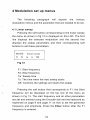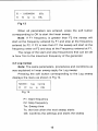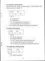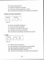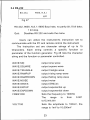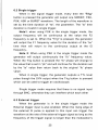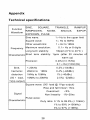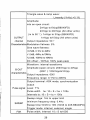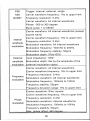
1
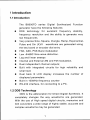
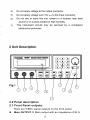
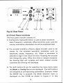
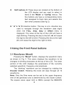
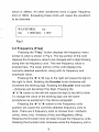
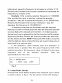
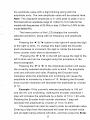
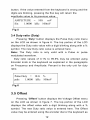
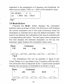
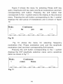
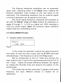
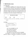
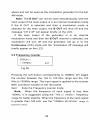
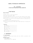
Protek
Test and Measurement
1
B8000FD Series
!
DDS Function Generator
Operators Manual
I
I
I
I
Contents
1 Introduction.........................................................................
I
1.1 Introduction..............................................................
I
1.2 DDS Technology........................................................ 1
1.3 Product Series ..........................................................2
1.4 General Information..................................................2
1.4.1 Contents..............................................................
2
..................................................................
1.4.2 Safety
2
2 Unit description ................................................................. 3
3
2.0 Front panel description.................................................
2.1 Front Panel Outputs ..................................................
3
2.2 Rear panel inputs..................................................... 4
2.3 Front panel controls................................................5
2.4 Front panel button description.....................................6
3 Using the front panel buttons............................................... 8
3.1 Waveform ................................................................
8
3.2 Frequency .................................................................. 9
.....-........I 0
3 .3 Amplitude ................................................
3.4 Duty Ratio..............................................................
12
3.5 Offset ..................................................................
12
3.6 Mode button........................................................
13
4 Modulation setup menus....................................................
15
4.1 Linear sweep .......................................................
15
4.2 Log sweep...........................................................
16
4.3 Frequency Shift key ...............................................
17
4.4 Phase Shift key.....................................................
17
.................................................
4.5 Amplitude shift key
17
...................................................................
4.6 Burst
18
4.7 FM ..................................................................... 18
4.8 Phase modulation..................................................
19
4.9 Internal Am modulation .........................................
19
4.10 External AM modulation .......................................19
20
4.1 1 Demo ..............................................................
5 Multifunction menu ...........................................................
21
21
5.1 Config button .....................................................
5.2 B out .............................................................. 21
22
5.3 Frequency counter .............................................
5.4 RS232............................................................23
6 External Trigger ................................................................
24
6.1 Trigger button ....................................................24
25
6.2 Single trigger .....................................................
6.3 External trigger ................................................. 25
7 StoreIRecall.....................................................................
26
Appendix technical Specifications ........................................
27
1 lntroduction
I.I
lntroduction
The B8000FD series Digital Synthesized Function
generator have the following features:
DDS technology for excellent frequency stability,
frequency resolution and the ability to generate very
low frequencies.
Very precise Sine, Square, triangle, Ramp, Exponential,
Pulse and Sin (X)/X waveforms are generated using
the key board or encoder dial entry
FSK, ASK, PSK Burst modulation
Low -54dBC Sine wave distortion.
Log and linear sweeps
Internal and External AM and FM modulation.
Dual independent channel outputs;
Built with integrated circuits for high reliability and
small size
Dual back lit LCD display increases the number of
displayed parameters.
Built in 100MHz frequency counter
RS-232 interface, for connecting to a PC.
1.2 DDS Technology
DDS is the abbreviation for Direct Digital Synthesis. It
completely changes the way waveforms are generated.
With the use of High speed digital circuits, memories and
DIA converters a wide range of highly stable, accurate and
complex waveforms may be generated.
1.3 Product series
There are four models to choose from in the B8000FD series
of DDS function generators with frequency ranges from 1pHz to
40MHz. These models include:
Model
Frequency
B8003FD
3MHz
B8010FD
B8020FD
10MHz
20MHz
B8040FD
40MHz
All models are easy to use and generate Sine, Square, Triangle,
Ramp, Exponential up, Exponential down, Pulse, sin (x)lx and noise
waveforms. They also provide a wide variety of modulations including:
Burst, Frequency shift key, Phase shift key, amplitude shift key, Am,
FM, PM along with Linear and Log sweep. All modulation and
waveform parameter values are entered in to user friendly menus with
a keyboard or an Encoder knob.
1.4 General Information
1.4.1 Contents
1 B8000FD series DDS Generator
1 AC power cord
1 BNC to Alligator clip test lead
1 Operating manual
1.4.2 Safety
1)
2)
3)
Before operating, read and understand the user manual
thoroughly on how to use this instrument.
Before connecting the power cord, verify that line input voltage
(1101220V) is set properly.
Use only a fast blow fuse. (250V AC, 0.25A)
4)
Do not apply voltage to the output connector.
5)
Do not apply voltage over 10V p-p to the input connector.
6)
Do not use or store this inst rument in a location near heat
source or in a place subject to high humidity.
This instrument should only be serviced by a competent
electronics technician
7)
2 Unit Description
2.0 Panel description
2.1 Front Panel outputs:
There are 3 BNC signal outputs on the front panel.
Main OUTPUT:@ Main output with an impedance of 50 R
SYN:Q This output is a TTL level signal which is active for
all waveforms except Sine and square waves. It is the
same frequency as the selected waveform at the main
output terminal and is used for synchronizing external
equipment to the generator.
For Sweep, the SYN signal is high during the time the
waveform is sweeping and low during the inactive time the
waveform is waiting for the next sweep to start.
When using FSK the positive portion of the sync signal is
high for the duration the FSK signal (TW) is at the first
frequency and low during the time the signal switches to the
second frequency (TS)
PSK the sync signal is high during the time the PSK signal
is at Zero phase (TW) and low during the time the signal
switches to the Phase shifted signal ( 1 s ) .
ASK the sync signal is high during the time the ASK signal
is active (TW) and low during the time it is inactive (TS),
waiting the next cycle to start
B OUT:@ Second output, with an impedance of 600Q. All
waveforms with a frequency to 20 KHz maybe selected. This
output signal may be used as the modulating signal when
using External AM.
2.2 Rear Panel Inputs
(1 1) External Trigger input (see fig 1A)
(12) External Frequency counter input
(13) Ext AM input
(14) AC line Voltage selector
(15) AC input
(16) RS232 connector
(12)
(13)
I
(14)
I
(15)
I
(1 6)
Fig.lA Rear Panel
2.3 Front Panel controls
The front panel controls consists of:
1) The Numeric keyboardQwhich is used to enter waveform
data (Frequency, amplitude, offset and Duty cycle.) and the
various modulation parameters as will be explained later.
2) The encoder knobOis a Rotary digital encoder used to set
values for the selected waveform parameter such as
amplitude, phase, frequency, etc. When a parameter is
selected a digit in the value will blink. Rotating the encoder
will change the value. When this knob is rotated clockwise,
the blinking digit will increase and when rotated counter
clockwise the blinking will decrease.
3) The Soft buttons @ are for selecting the menu items when
the Mode or Config Menus are displayed. The Soft buttons
are assigned to corresponding parameters: Example: When
the MODE key is pressed, the Mode selection menu is
displayed on the LCD@ as shown in Figure 2. In this
example, continuous (CW) which is displayed adjacent to
mode is the currently selected item. Pressing the soft button
corresponding to > displays the next group of modulations.
c
i
Mode:
Continuous
Fig 2:
4) The front panel keysQ are of 3 types. The first is the single
function buttons that displays waveform, frequency,
amplitude. DC offset and duty ratio values when pressed.
The Soft buttons are not used within these buttons.
5) The second type are the keys that display more than one
menu item on the LCD when pressed. The Mode and
Config keys are examples. These Soft buttons are used to
select items when multiple menu items are displayed.
6) The third type are execution buttons. The Enter key enters
waveform parameter values, the Esc key cancels an input
value after entering it from the key board. The direction key
( 4 " & " b ) @navigates through the displayed numerical
value on the LCD and the Trig key for performing single
cycle and external trigger waveform operations.
2.4 Front panel button description:
"Mode":When pressed displayes the modulation option menus.
6
"Config": This key when pressed selects the B OUT put,
Frequency Counter and RS232 menus.
"Trig": When Burst, ASK, PSK or FSK modulation has
been selected (see chapter on the Trigger
functions), pressing the "Trig" key, the generator
enters the Single trigger mode. Pressing the Trig
key again the generator will output one
waveform.
The External trigger input is also enabled. A
signal applied to the External trigger input will
externally trigger the generator at the rate of the
External input signal.
"Enter: Enters and stores the numeric data which has been
entered from the Key board or
the rotary
dial
"Esc: cancels the current keyboard or rotary dial data
operation and displays the data that was
previously entered. If the triggered operation was
previously selected, pressing this key will return
the unit to normal operation.
Keyboard buttons@ enters data values in to the upper
portion of the display of the selected
waveform parameter. Pressing the ENTER
key enters the new data. If the data entered is
incorrect, pressing the ESC key will return
the display to the previous value.
Soft buttons @ These keys are located at the bottom of
the LCD display and are used to select in
items in the "Mode" or "Config" menus. The
five buttons are have a corresponding menu
item assigned to them item and selects this
item when pressed (See fig 2).
" 4 "& " b " @ direction button. This key is a bi- direction key
used to navigate through the waveform data digits
when the Freq., Amp, Duty or Offset menu is
displayed. The value at the top of the LCD will have a
digit blinking. Pressing this key to the left ( 4 )will cause
the digit to the left to blink. Pressing this key to the right
( b ) will cause the digit to the right to blink.
3 Using the Front Panel buttons
3.1 Waveforms (Wavef)
Pressing the "Wavef" button, displays the waveform menu
as shown in Fig 3. This menu displays the waveform to be
changed in blinking characters at the top of the LCD. The lower
portion of the LCD displays the parameters of the currently
selected waveform, frequency and amplitude.
The "blinking" waveform can be changed by rotating the
Encoder knob@. Rotating this knob will step through all 10
waveforms,
Note: Only the Sine wave can be set to the upper frequency
limit of the generator and is determined by the model number.
The square wave upper limit is 5MHz (except the B8003FD
8
which is 3MHz). All other waveforms have a upper frequency
limit of 1MHz. Exceeding these limits will cause the waveform
to be distorted.
o,
WAVEFORM:
Fig 3
3.2 Frequency (Freq)
Pressing the "Freq." button displays the frequency menu
similar to what is shown in Fig 4. The top portion of the LCD
displays the Frequency value to be changed with a digit blinking
along with its frequency units. The new frequency value is
entered here. The lower portion of the LCD displays the
currently selected waveform, along with its frequency and
amplitude value.
Pressing the 4 " & "b key to the right will cause the digit to
the right to blink. Rotating the Encoder knob clockwise will
increment the blinking digit. Rotating the Encoder knob counter
- clockwise will decrement the Digit. Pressing the
4 " & "b button to the left will cause the digit to the left to blink.
To change the value of the blinking digit use the same
procedures as explained in the above paragraph
Pressing the 4 " & "b button to the Frequency units
position will cause the currently selected frequency units to
blink. There are 5 frequency units to choose from: millihertz
(mHz), Hertz (Hz), Kilohertz (KHz) and Megahertz (MHz).
Rotating the Encoder knob will step through the frequency units.
Rotating the Encoder knob clockwise while the frequency unit is
blinking will cause the frequency to increase by a factor of 10.
Rotating the Encoder knob counter clockwise will decrease the
frequency by a factor of 10.
Example: If the currently selected frequency is 1.0000000
KHz and the KHz units is blinking, rotating the encoder
clockwise 1 step will increase the frequency to 10.000000 KHz.
Rotating the Encoder knob counter clockwise 1 step will
decrease the frequency to 100.00000 HZ
A frequency value may also be entered using the keyboard.
Pressing a number on the key board will enter the keyboard value (the
previous digits will be cleared) and it will blink. An 8 digit value plus
decimal point may be entered from the Key board and all the entered
digits will be blinking. Pressing the Enter key confirms the new value
and the blinking will stop. NOTE: Pressing the ESC button at any time
while the digits are being entered (blinking) will cause the frequency to
revert back to its previous value.
If the frequency value entered from the keyboard or
encoder know is greater than the upper frequency limit of the
selected waveform, the frequency value will default to the upper
frequency limit of the
specifications for this unit)
selected
waveform.
(See
the
0
1
Fo = 1.000000 KHz
Fig 4
3.3 Amplitude (Amp)
Pressing the "Amp" Button displays the amplitude menu similar
to what is shown in Fig 5. The top portion of the LCD displays
the amplitude value with a digit blinking along with the
amplitude units. The new amplitude value will be entered here.
Note: The displayed amplitude is in volts peak to peak in to a
50Q load with an amplitude range of 1.00mV to 10.0 Volts for the
models with frequencies of 20 MHz or less (1.00mV to 3.00V for the
model B8040FD)
The lower portion of the LCD displays the currently
selected waveform, along with its frequency and amplitude
value.
Pressing the 4 " & " b button to the right will cause the digit
to the right to blink. To change this digit rotate the Encoder
knob clockwise to increment the digit or rotate the Encoder
know counter clock wise to decrement it.
Pressing the 4 " & " b to the left will cause the digit to the
left to blink and can be changed using the procedure in the
above paragraph
Pressing the 4 " & " b to the Amplitude position will cause
the currently selected amplitude units to blink. The amplitude
units are millivolts and volts. Rotating the Encoder knob
clockwise while the amplitude unit is blinking will cause the
amplitude to increase by a factor of 10. Rotating the Encoder
knob counter clockwise will decrease the amplitude by a factor
of 10.
Example: If the currently selected amplitude is 100 mV
and the mV unit is blinking, rotating the encoder clockwise 1
step will increase the amplitude by a factor of 10 to 1 .OO volts.
Rotating the Encoder knob counter clockwise 1 step will
decrease the amplitude by a factor of 10 to 10.0mV.
The keyboard can also be used to enter an amplitude value.
Entering a digit from the keyboard will clear the current value
and all digits being entered will blink, and then press the Enter
11
button. If the value entered from the keyboard is wrong and the
digits are blinking, pressing the Esc key will return the
am litude value to its revious value.
1
Fig 5
3.4 Duty ratio (Duty)
Pressing "Duty" button displays the Pulse Duty ratio menu
on the LCD as shown in figure 6. The top portion of the LCD
displays the Duty ratio value with a digit blinking along with a %
symbol. The new Duty ratio value is entered here.
Note: The Duty ratio is only valid with a Pulse or pulse
modulated waveform.
Duty ratio values of 0.1% to 99.9% may be entered using
Encoder knob or the keyboard as explained in the paragraphs
on Frequency and Amplitude. Percent is the only unit for duty
ratio.
p"
1.0000 kHz
lOOmV
Fig 6
3.5 Offset
Pressing "Offset" button displays the Voltage Offset menu
on the LCD as shown in figure 7. The top portion of the LCD
displays the offset value with a digit blinking along with a %
symbol. The new Duty ratio value is entered here. The Offset
value may be entered using the encoder dial or the keyboard as
explained in the paragraphs on Frequency and Amplitude. An
offset may be added -100% to + 100% of the waveform value.
0
DCOFFSET
=
0. %
Fig 7
.
3.6 Mode Button
Mode" button displays the modulation
selection menu as shown in Fig 8. The first line on LCD displays
the current modulation and in this case Continuous wave (no
modulation) is selected and is also the default modulation. The
second line displays the modulations that may be selected with
a corresponding soft button. The soft button when pressed the
first time displays the selected modulation on the top line,
pressing it again displays the modulation setup menu.
Pressing the
Continuous
Fig 8
The modulations that can be selected in figure 8 are:
Linear Sweep (Lin) Log sweep (Log), Frequency shift key (fsk).
z
The soft button that corresponds to the > symbol when pressed
displays the next group of modulations as shown in Fig 9
Continuous
burst
Fig 9
13
Figure 9 shows the menu for selecting Phase shift key
(psk), Amplitude shift key (ask) and Burst modulations and their
corresponding soft button. Pressing the soft button that
corresponds to the < symbol returns the display to the previous
menu. Pressing the soft button corresponding to the > symbol
displays the next group of modulations and is shown in figure
10
c
Continuous
Fig 10
Fig 10 shows the menu for selecting frequency
modulation (fm), Phase modulation (pm) and the amplitude
modulation (am) and their corresponding Soft buttons.
Pressing the soft button corresponding to the > symbol
displays the EXT amplitude selection menu and a waveform
demo as shown in fig 11.
Continuous
extam
Fig 11
4 Modulation set up menus
The following paragraph will explain the various
modulation menus and the parameter that are needed to be set.
4.1 Linear sweep
Pressing the soft button corresponding to the linear sweep
the menu as shown in fig 12 is displayed on the LCD. The first
line displays the selected modulation and the second line
displays the sweep parameters and their corresponding soft
buttons to set these parameters.
MODE:
linear sweep
Fig 12
F1: Start frequency
F2: Stop frequency
Tw: Sweep time
Ts: The time when the next sweep starts
OK: Confirms the settings and starts the sweep
.J
Pressing the soft button that corresponds to F1, the Start
frequency will be displayed on the top line of the menu as
shown in Fig 13. The start frequency and all other parameters
are set and entered using the Encoder dial and the keyboard as
explained on page 9 and page 11 on how to set the generator
frequency and amplitude. Press the Enter button after the F1
frequency is entered.
Fig 13
When all parameters are entered, press the soft button
corresponding to OK to start the linear sweep.
Note: If F1 frequency is greater than F2 the sweep will
start at the frequency entered by F1 and stop at the frequency
entered by F2. If F2 is less than F1 the sweep will start at the
frequency enter at F2 and stop at the Frequency entered at F1,
The range of the start and stop frequencies that can be set
is from 1Hz to the maximum frequency of the generator
4.2 Log sweep
Note: The same parameters, procedures and conditions as
was explained in linear sweep apply for Log sweep.
Pressing the soft button corresponding to the Log sweep
displays the menu as shown in Fig 14.
1-
fl
f2 tw
ts
Fig 14
F1: Start frequency
F2: Stop frequency
Tw: Sweep time
Ts: the time when the next sweep starts
OK: Confirms the settings and starts the sweep
16
4.3 Frequency shift keying:
Pressing the soft button corresponding to FSK displays the
menu as shown in figure 15
7
1
MODE:
1
Fig 15
F1: frequency 1
F2: frequency 2
Tw: the working time of frequency 1
Ts: the working time of frequency 2
OK: Confirms the settings and starts the waveform
4.4 Phase shift keying
MODE:
Fig 16
Fo: Carrier frequency
Ph: phase difference
Tw: the 0 phase shifted signal working time
Ts: the phase shifted signal working time
OK: Confirms the settings and starts the waveform
4.5 Amplitude shifting keying
V
l
MODE:
Fig 17
Fo: Carrier frequency
Ph: Carrier phase shift
Tw: Carrier frequency duration
Ts: the time the next waveform starts
OK: Confirms the settings and starts the waveform
4.6 Burst (Pulse waveform)
MODE:
BURST
Fig 18
Fo: Burst waveform frequency
Ph: the burst starting phase
Co: Number of cycles in the burst
Ts: the time the next burst starts
OK: Confirms the settings and starts the burst
9
1
4.7 FM
Fig 19
Fo: Carrier wave frequency
Fm: Modulating wave frequency (modulation)
Fd: Max frequency deviation (deviation)
Wa: Modulating waveform (wave)
Ok: Confirms the settings and starts the waveform
1
4.8 Phase modulation
Eoz
ne;:
1
Fig 20
Fo: Carrier wave frequency
Fm: Modulating wave frequency (modulation)
Pd: Max phase deviation (deviation)
Wa: Modulating waveform (wave)
OK: Confirms the settings and starts the waveform
4.9 Internal AM modulation
Fig 21
Fo: Carrier wave frequency
Fm: Modulation wave frequency
Dp: Amplitude modula1:ion depth ( % modulation)
Wa: Modulating waveform
OK: Confirms the settings and starts the waveform
0
1
4.10 External AM modulation
extam
demo
The External amplitude modulation has no parameter
setup menu. Selecting extam in the Mode menu enables the
External modulation input located on the rear panel of the
instrument. The modulating waveform from an external signal
or function generator can be applied to this input.
The carrier signal frequency, amplitude and waveform is
set with the WaveF, Freq and Amp buttons as explained on
pages 8 through II.A 0.4V p-p signal will 100% modulate a
1Volt p-p carrier signal. Note: the auxiliary output waveform
maybe used as a modulating source.
4.1 1 Demo (B8040 FD only)
1 1. Lissajous pattern demonstration
Phase=O
< extam demo
Fig 23
In this mode the generator outputs the same frequency
sine wave on both the main output and the B OUT terminals
simultaneously. The frequency is set by the Freq button.
Set an oscilloscope to the X-Y mode and connect the
main output to the X input of the oscilloscope and the B OUT to
the Y input. Adjust the phase difference between the signals
by rotating the Encoder knob and observe the pattern on the
oscilloscope.
This mode may be also used when 2 signals of the same
frequency but have different phases is needed for an
application.
Pressing the "Config" button displays Mulli funct menu
as shown in Fig 24. When this key is pressed the LCD displays
the items that may be selected. These items are: CH2 (B OUT),
frequency counter (fin) and RS232. Pressing the corresponding
soft button displays the setup menu for the selected item. The
procedure to select menu items and parameters are the same
as explained in the above paragraph on Mode button.
u
i
MULTIFUNC MENU
Fig 24
5.2 B OUT
-- CHANNEL2 SETUP -off
wave
fa
amp1 OK
Fig 25
Off: Turns the B OUT On or Off
Wave: selects the Waveform
Fa: selects the Frequency
Ampl: selects the Amplitude
OK: Confirm the new setup and starts the B OUT
The B OUT is an auxiliary low frequency DDS function
generator capable of outputting all waveforms as described
21
above and can be used as the modulation generator for the Ext
AM mode.
Note: The B OUT can not be used simultaneously with the
main output if the main output is in an internal modulation mode.
If the B OUT is selected and then a modulation mode is
selected for the main output, the B OUT will shut off and the
message "CH 2 off" will appear briefly on the LCD.
If the main output of the generator is in an internal
modulation mode and then the B OUT channel is selected, the
modulation will turn off and the generator will go in to the
Continuous (CW) mode and the "modulation off message will
briefly appear on the LCD.
5.3 Frequency counter
FREQin =
< lOOMHz
quit
Fig 26
Pressing the soft button corresponding to 100MHz will toggle
the counter between the 1Hz to 100 KHz range and the 100
KHz to 1OOMHz range. The input signal is applied to the counter
BNC connector located on the rear panel.
Quit:
Exits the Frequency counter mode
Note: When the frequency of input signal is less than
IOOkHz, it is suggested using the "1Hz to IOOkHz", frequency
range for better stability. When the frequency of the input signal
is greater than 100 kHz, use the "100KHz t6100MHz" range to
prevent errors.
RS-232,
9600, N,8,l
quit
Fig 27
.
I
RS-232, 9600, N,8,1: 9600 Baud rate, no parity bit; 8 bit data;
1 bit stop.
Disables RS 232 and exits the menu
Quit:
I
Users can utilize the instrument's instruction set to
I
communicate with the PC and remote control the instrument
The Instruction set are character strings of up to 15
Characters. Each string controls a specific function or
parameter of the function generator. Fig 28 lists the character
string and the function or parameter controlled.
output sine wave
WAVE:SQUARE
output square wave
WAVE:TRIANGLE
output triangle wave
WAVE:RAMPUP
output rising ramp wave
WAVE:RAMPDOWN
output falling ramp wave
WAVE:NOISE
WAVE:SINX/X
output noise
WAVE:EXPUP
output exponential up
WAVE:EXPDOWN
output exponential down
FREQIOOO
Sets the frequency to 1000Hz
output SIN(x)/x
The
range
to1 5,000,000
is
from
0.001
Sets the amplitude to IOOmV, the
range is ImV to 10,000mV
Sets the pulse ratio to 50% duty
ratio. The duty ratio range is 20% to
80%
Set the DC of set offset to 0%. The
DC offset, range is -100% to + l o o %
Fig 28
Each instruc.tion must not exceed 15 characters.
Every instruction must end with ";" or with a return
character to indicate that the instruction set is sent out. The
ASCII code of a new line character is 10, but it is indicated by
"\nu in C language. If there is no ending character in the
instruction set, the ins.trument may "lock up" and be restarted.
There should be sufficient time between two instruc1:ion so
as to allow enough time for the instrument to finish the current
operation.
6 External Trigger
6.1 Trigger Button
When in the SWEEP, FSK, ASK and BURST modes it may
be at times desirable to execute one cycle at a time. The
B8000FD series of DDS generators have single cycle and
external trigger capability.
Pressing "Trig" key once, the instrument enters into
triggered mode. The LCD will display "trig" on the bottom right
side of the LCD. If the "MODE" key has been pressed, the word
"MODE" will change to "MODE (T)".
6.2 Single trigger
When in the signal trigger mode, every time the "Trig"
.
i
iI
button is pressed the generator will output one SWEEP, FSK,
PSK, ASK or BURST waveform. The length of the waveform is
set by the time duration of "tw", the parameter. The "ts" time
duration is invalid in single trigger.
Notel: when using FSK in the single trigger mode, the
output frequency will be continuous at the value the F2
frequency is set to. When the "Trig" is pressed, the generator
will output the F1 frequency value for the duration of the "tw"
time then will return to the continuous output at the f2
frequency..
Note 2: When using PSK in the single trigger mode the
generator will output continuously the "fo" frequency value.
When the Trig button is pressed the "fo" phase will change to
the value that is set in "ph" and will continue for the duration set
by the "ts" value then return back to the original "fo' phase
value.
When in single trigger, the generator outputs a TTL level
pulse though the SYN output when the Trig button is pressed
which can be used to trigger an oscilloscope.
Single trigger mode requires that there is no signal input
through BNC; otherwise they can interfere which each other
?
6.3 External trigger
When the generator is in the single trigger mode the
External trigger input is also enabled. When the rising edge of
the external ttl pulse is applied to this input can trigger the
waveform at the rate of the external trigger signal as long as the
frequency of the trigger signal is longer than the modulation's
"ts" width duration
To exit the trigger mode, press the "Esc" button. The "trig"
symbol will disappear in a non modulation mode or the (T) in a
modulation mode and the instrument will return to the internal
trigger mode.
7 Store /Recall (B8040FD)
--- STOREIRECALL--Memory:
Fig 29
The Store function saves all current parameters and modes,
while the Recall function recalls and get back to the saved
parameters and modes.
Parameters and modes, like waveforms, frequency,
amplitude, duty ratio, DC off set, modulation, B OUT, etc, can
be saved or recalled all at one time. When recall the saved
settings, the instrument applies the saved settings.
Adjust the encoder dial to select the memory unit position,
from 1 to 20, all together 20 memory units.
5.1 How to store:
Pressing the Store button displays the store menu as
shown in Fig.30 with the 1 blinking
--- STORE---
Memory:
Use the encoder dial to select memory location from 1 to
20. Press Store button to save the current waveform parameter
settings to the selected memory location. If the current memory
unit already has stored data, a message "--memory full--",
"overwrite?" will appear on the LCD. To overwrite, press the
Store button again; otherwise, press the Esc button and enter a
different memory Number
5.2 How to recall:
Pressing Recall button displays the menu as shown in
Fig.31 with the 1 blinking
---
RECALL---
Memory:
Use the encoder dial to select a memory location from 1 to
20. Press Recall button again to recall the stored data. The
generator will be set to the parameters that are stored in the
selected memory location. If there is no stored data in the
current memory unit, a message "ERROR",
"memory
empty!" will appear on the LCD briefly. Then the instrument will
automatically return to the recall menu. A different memory
location should be selected.
Appendix
Technical specifications
RAMPUP,
SINE,
SQUARE,
TRIANGLE,
RAMPDOWN,
NOISE,
SIN(X)/X,
EXPUP,
EXPDOWN, PULSE
Sine wave:
1 P Hz to the upper limit
Square wave:
1 P Hz to 5MHz
Other waveforms:
1 II Hz to 1MHz
0.1 P Hz or 8 digits
Frequency Maximum resolution:
Long term stability:
50ppm (0°C to 40°C )
Characteristicshort term stability: I p p m (after 20 minutes of
warm up)
0.4Hz(>3.1 KHz)
Precision:
0.1 P Hz(<IOOmHz)
Function
Waveform
Sine,
< 20kHz
20kHz to 1MHz
harmonic
1MHz to 10MHz
distortion
(50 ? load, 10MHz to 20MHz
I V p p output)
Signal
0.2% (-54dBc)
0.4% (-48dBc)
1% (-40dBc)
2.5%( -22dBc)
Square wave: (50? load @ I V p p output)
Rise and fall times< 15ns
Overshoot:
<5%
Non linearity 1%+20ns
Pulse wave:
Characteristic
Duty ratio: 0.1 % to 99.9% (< 10kHz)
1% to 99% ( < I 00kHz)
3% to 97% (c1MHz)
Triangle wave & ramp wave:
Linearity ( I kHz):<O.l%
Amplitude:
into an open circuit:
2mVpp to 6Vpp(B8040FD)
2mVpp to 20mVpp (All other units)
(in to 50 ? ): ImVpp to 3Vpp (B8040FD)
ImVpp to1 0Vpp (All other units)
Output impedance: 50 ?
OUTPUT
channel
Characteristics Modulation flatness: 5%
Sine wave flatness:
<0.5dB, 0.1Hz to 4MHz
<I
.OdB, 4MHz to1OMHz
<2.0dB, 10MHz to 40MHz
DC offset: -100%to 100% peak-peak
Waveform: internal waveforms
Amplitude (open circuit): 200mVpp to 20Vpp
B OUT
(600? ): 1OOmVpptol OVpp
characteristics
Output impedance: 600?
Frequency range: 0.1 Hz to 20KHz
Output terminal: ASK mode, synchronization
output
Pulse signal Level: TTL
Pulse width tw: 10 1* S < tw < 100s
Intervals ts: 10 1* S < ts < 100s
SWEEP
FSK
Sweep range: 1Hz to upper limit
minimum frequency step: 0.4Hz
Sweep time:lOmS to 1 0 s (1 Oms to 4 0 s B8040FD)
Trigger mode: internal, external, single
Pulse width, internal: 10 1* S tolOOS
odulation waveform: All internal waveforms
odulation frequency: 100mHz to 10KHz
arrier waveform frequency: 1Hz to upper limit
Frequency resolution: 0.4Hz
Modulation waveform: internal waveforms
Frequency
counter
Ranges
Tested frequency range: 1 Hz to 1OOMHz
Input signal: >100mV
1Hz to 100Khz and 1OOKHz to 1OOMHz
1
1
Specifications are subject to changes without notice.
Protek Test & Measurement
45 Smith Street, Englewood, NJ 07631, USA
Fax: + I -201-227-1169
Tel: +I-201-227-1161
Email: [email protected]
http://www.protektest.corn