Transcript
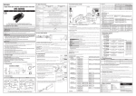
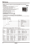
Specifications
PANEL METER
MT4Y
100-240VAC 50/60Hz (90 to 110% of rated voltage)
5VA
7Segment LED Display(Red)
23℃ ± 5℃ ☞ DC Type: F.S.±0.1% rdg±2digit / AC Type: F.S.±0.3% rdg±3digit (Frequency: F.S.±0.1% rdg±2digit)
Display accuracy
F.S +0.3% rdg +3digit max. only for 5A terminal.
-10℃ to 50℃ ☞ DC/AC Type: F.S.±0.5% rdg±3digit
Input
DC Voltage/Current, AC Voltage/Current, AC Frequency
Max. allowable input
110% F.S. for input spec.
A/D conversion method Practical oversampling using successive approximation ADC
Sampling cycle
50ms (DC), 16.6ms (AC 60Hz) (1/12,000)
Max. indication range
-1999 to 9999 (4Digit)
Relay output ☞ Contact capacity:250VAC 3A, 30VDC 3A/Contact composition:N.O(1a)
Preset output
NPN/PNP Open Collector output ☞ 12-24VDC ±2V 50mA Max. (Load resistance)
RS485 communication output ☞ Baud rate: 1200/2400/4800/9600, Transmission method: 2 wires half duplex,
Sub output
Tuning method: Asynchronous method, Protocol: Modbus typ
(Transmission output)
Serial/BCD output ☞ NPN Open collector output, 12-24VDC Max. 50mA(Resistive load)
DC4-20mA output ☞ Resolution: 12,000division (Load resistance max. 600Ω), Response time:Max. 450ms
AC measuring function Selectable RMS or AVG
Frequency
Measurement range:0.100 to 9999Hz(Fixed decimal point type)
measuring function
Hold function※1
Includes(Outer hold function)
MT4Y SERIES
M
A
N
U
A
Display cycle delay function [PA 2: DIS.T mode]
Series
Power supply
Power consumption
Display method
L
●
●
In some applications the measured input may fluctuate which in turn causes the display to fluctuate. By adjusting the
display cycle delay function time in the DIS.T mode in parameter 2, the operator can adjust the display time within
a range of 0.1 sec to 5 sec. For example, if the operator sets the display cycle time to 4.0 sec., the display value
displayed will be the average input value over 4 sec. and also will show any changes if any every 4 sec.
Parameter
Parameter
Display
Input type
Input range
Display
Standard
Frequency
Scale
High scale
Low scale
Dot
IN-T
IN-R
DISP
STND
FREQ
SCAL
H-SC
PA1
L-SC
(Parameter 1)
DOT
●
INB.H
Input bias high
●
INB.L
Input bias low
INB.E
Input bias exponent
OUT.T
HYS
Out type
Hysteresis
Startup compensation
Set startup compensation time
time
Set monitoring delay time for
Peak time
peak value(sec)
Display time
Set sampling time(sec.)
Set usage of front side zero
Zero key
adjustment key
●
Thank you very much for selecting Autonics products.
For your safety, please read the following before using.
Caution for your safety
※Please keep these instructions and review them before using this unit.
※The following is an explanation of the symbols used in the operation manual.
caution:Injury or danger may occur under special conditions.
Warning
1. In case of using this unit with machinery(Ex: nuclear power control, medical equipment, ship, vehicle,
train, airplane, combustion apparatus, safety device, crime/disaster prevention equipment, etc) which
may cause damages to human life or property, it is required to install fail-safe device.
It may cause a fire, human injury or damage to property.
2. It must be mounted on Panel.
It may give an electric shock.
3. Do not connect, inspect and repair terminals when it is power on.
It may give an electric shock.
4. Do not disassemble and modify this unit, when it is required. Please contact us.
It may cause an electric shock and a fire.
5. Please check the number of terminal when connecting power line or measured input.
It may cause a fire.
1. This unit shall not be used outdoors.
It might shorten the life cycle of the product or give an electric shock.
2. When connecting wire, 20AWG(0.50mm²) should be used and tighten screw bolt on terminal block with 0.74N•m
to 0.90N•m strength.
It may cause a malfunction or fire due to contact failure.
3. Please observe the rated specification.
It might shorten the life cycle of the product and cause a fire.
4. Do not use beyond of the rated switching capacity of Relay contact.
It may cause insulation failure, contact melt, contact failure, relay broken and fire etc.
5. In cleaning the unit, do not use water or an oil-based detergent.
It might cause an electric shock or fire.
6. Do not use this unit in place where there are flammable or explosive gas, humidity, direct ray the sun,
radiant heat, vibration and impact etc.
It may cause a fire or explosion.
7. Do not inflow dust or wire dregs into the unit.
It may cause a fire or mechanical malfunction.
8. Please connect properly after checking the polarity of measuring terminals.
It may cause a fire or explosion.
Type
DC Volt
+0.5
-0
31.5
Min. 40
68+0.7
-0
(Unit: mm)
Terminal connection
MT4Y - DV - 4
●
1
2
●
3
4
5
250mV/50mV
5V/1V
50V/10V
500V/100V
6
1
SOURCE
100-240VAC
50/60Hz 5VA
5
9
2
3
COM
10
11
8
HOLD/ZERO
GO
LO
- 42]
12
●
SOURCE
100-240VAC
50/60Hz 5VA
5
6
COM
10
11
GO
8
HOLD/ZERO
12
10
SOURCE
100-240VAC
50/60Hz 5VA
LO
9
12
10
11
- 41]
OUT1
- 43]
13
- 45]
13
0.0 to 500.0(Fixed)
0-100V
[100V]
4.33315㏁
0 .0 to 100.0(Fixed)
0-50V
[ 50V]
433.15㏀
0.00 to 50.00(Fixed)
[10V]
433.15㏀
0.00 to 10.00(Fixed)
0-5V
[ 5V]
43.15㏀
0.000 to 5.000(Fixed)
0-1V
[1V]
43.15㏀
0.000 to 1.000(Fixed)
0-250mV
[ 0.25V]
2.15㏀
0.00 to 250.00(Fixed)
0-50mV
[ 50MV]
2.15㏀
0.00 to 50.00(Fixed)
0-5A
[ 5A]
0.01Ω
0.000 to 5.000(Fixed)
0-2A
[ 2A]
0.01Ω
0.000 to 2.000(Fixed)
[ 0.5A]
0.1Ω
0-200mA
[ 0.2A]
0.1Ω
0.0 to 500.0(Fixed)
0.0 to 200.0(Fixed)
0-50mA
[ 50MA]
1.0Ω
0.00 to 50.00(Fixed)
4-20mA
[ 4-20]
1.0Ω
4.00 to 20.00(Fixed)
0-5mA
[ 5MA]
10.0Ω
0.000 to 5.000(Fixed)
0-2mA
[ 2MA]
10.0Ω
0.000 to 2.000(Fixed)
0-500V
[ 500V]
4.987㏁
0.0 to 500.0(Fixed)
0-250V
[ 250V]
4.987㏁
0.0 to 250.0(Fixed)
0-110V
[110P]
1.087㏁
0.0 to 440.0(Fixed)
0-50V
[ 50V]
1.087㏁
0.00 to 50.00(Fixed)
0-20V
[ 20V]
200㏀
0.00 to 20.00(Fixed)
0-10V
[10V]
200㏀
0.00 to 10.00(Fixed)
0-2V
[ 2V]
20㏀
0.000 to 2.000(Fixed)
0-1V
[1V]
20㏀
0.000 to 1.000(Fixed)
0-5A
[ 5A]
0.01Ω
0.000 to 5.000(Fixed)
0-2.5A
[ 2.5A]
0.01Ω
0.000 to 2.500(Fixed)
0-1A
[1A]
0.05Ω
0.000 to 1.000(Fixed)
0-500mA
[ 0.5A]
0.1Ω
0.0 to 500.0(Fixed)
0-250mA
[ 0.25A]
0.1Ω
0.0 to 250.0(Fixed)
[ 0.1A]
0.5Ω
0.0 to 100.0(Fixed)
[ 50MA]
0.5Ω
0.00 to 50.00(Fixed)
Press
+ +
NO
2
- 46]
HOLD/ZERO
9
CLOCK
10
DATA LATCH
11
12
POL
COM
8
10
A
C
D0
D2
DOT
COM
B
D
D1
D3
1
13
3
5
7
12
14
4mA
FS-L
11 13
Error correction function
Time chart of Low-speed serial output and BCD output
tw
◎Low-speed serial output(Negative logic)
*tw
tb
t : 7.8ms
ta : 0.5ms
tw : 5ms
tb : 2.3ms
Digit signal
Data
Input data
t : 20ms
ta : 0.05ms
tw : 5ms
tb : 4.95ms
Latch
*ta
t
Cn-1
Clock
t
Data
31ms
*tb
Cn
C1
Dn-1
Dn
D1
Data
1 2 3 4 5 6 7 8 9 10 11 12 13 14 15 16 17 18 19 20
input
DP D C B A DP D C B A DP D C B A DP D C B A
Clock
D3
D2
1 2
DP D
D1
Data H H L H H H H H
D0
A
B
C
D
L
H
L L L
H H
H H H H H L
H
L
L
H
L
H
H
H
H
H
H
H
H
*tw
L
H
*ta
*tb
Latch
Display
H
*When clock pulse is changed from High to Low, Data will be output.
Prescale function[PA1: H-SC/ L-SC mode]
This function is to display setting(-1999 to 9999) of particular High/Low-limit value in order to display High/Low-limit
value of measured input. If measured inputs are 'a' or 'b' and particular values are 'A' or 'B', it will display a=A, b=B
as below graphs.
Display
B
Display
B
A
A
a b
Input value
Display
B
a b
Input value
b
A
B
Display
A
Input value
a
a
b
Input value
A
Display
B
b
A
b
Display
B
Input value
Input value
Flashes when measured input is exceeded the max.allowable input (110%)
Flashes when measured input is exceeded the min.allowable input (-10%)
Flashes when display input is exceeded H-SC setting value
Flashes when display input is exceeded L-SC setting value
※Error display is released automatically when it is in the measuring and display range.
※" LLLL" is displayed when the measured input is 4-20mA.
※After flashing " OVER" 2 times when it exceeds the zero range, it returns to RUN mode.
Monitoring peak display value function
[PA 0: H.PEK/ L.PEKmode, PA 2: PEK.Tmode]
It monitors max./min. value of display value based on current display value and then display the data in H.PEK mode and L.PEK
mode of parameter 0. Set delay time(0 to 30 sec.) in PEK.T mode of parameter 2 in order to avoid caused by initial overcurrent
or overvoltage, when monitoring the peak value. Delay time is 0 to 30 sec. and it starts to monitor the peak value after set time.
keys are pressed at H.PEK and L.PEK mode of parameter 0, it will be initialized.
When
※Monitoring function is not indicated when setting the PEK.T of parameter 2 as " 00 S".
※The above specifications are subject to change without notice.
0.10 to
99.99Hz
0.0
Max. value by data monitoring
Low peak
Min. value by data monitoring
0.1 to
999.9Hz
1 to
9999Hz
Input correction
Front key
value
PA1: Direct
Press both ,
input correction
keys for 3 sec.
Description value method
at the measuring
at INB.Lmode mode.
Input external
signal
Short-circuit
external Hold
terminal no.12,
13 over min.50m.
※Refer to description " Error correction function, Error
display function, Parameter 2" for function and error.
Description
H: Hysteresis
OFF
No output
lST
GO
LO
If it is equal or lower than Low setting value, LO output is ON. If it is
higher than Low setting value, GO output is ON.
hST
HI
GO
If it is equal or higher than High setting value, HI output is ON. If it is equal
or lower than High setting value, GO output is ON.
LhST
HI
GO
LO
LO output is ON when it is equal or lower than Low setting value. HI output
is ON when it is equal or higher than High setting value. GO output is ON
when it is higher than Low setting value, and lower than High setting value.
HhST
HI
GO
LO
LO output is ON when it is equal or higher than Low setting value. HI output
is ON when it is equal or higher than High setting value. GO output is ON
when it is lower than Low/High setting value.
HI
GO
LO
LO output is ON when it is lower with Low setting value. HI
output is ON when it is equal or lower than High setting value. GO output is
ON when it is higher than Low/High setting value.
LlST
It is operated same with lSTbut LO output does not operate under
initial Low set value, and it is ON from under next Low setting value.
If this is higher than Low setting value, GO output will be ON.
※hSET/ lSET is displayed according to the setting of output operation mode, when user set "OFF", hSET/ lSETdoes not displayed.
※RS485 / DC4-20mA provide lSTonly.
※BCD Dynamic output / Low speed serial output are not available.
LdST
GO
LO
,
or
key.
RUN
※Press MODE key for 2 sec. in RUN mode,
[ PA1](Parameter 1) is displayed.
MODE
Set preset High-limit value.
(When set the preset only)
※Change to set with
keys.
Set preset Low-limit value.(When set
the preset only)
※Change to set with
keys.
MODE
It shows High-limit monitoring value
(High Peak) in RUN mode. It is
initialized by pressing
key.
MODE
It shows Low-limit monitoring value
(Low Peak) in RUN mode. It is
initialized by pressing
key
※When PEK.T of Parameter2 is set as " 00 S", monitoring
function is not displayed.
2sec
[ PA2] is displayed after [ PA1].
When MODE key is pressed continually,
PA1
it stops displaying at [ PA2].
MODE key ※It is advanced to current display parameter
2sec
releasing MODE key at [ PA1] or [ PA2].
※Press MODE key for 3 sec., it is returned
PA2
to RUN mode at any position.
※After returning to RUN mode, if MODE key is
pressed within about 2 seconds again, it is
entered into [ PA1] or [ PA2] again.(Refer to
the below each parameter setting description.)
MODE
Parameter 1
<Specification chart of measured input by each items>
Item
Select measured input specification.
(Refer to " Specification of
measured input and range".)
Range of measured input
MT4Y-DV 500V 100V 50V 10V 5V 1V 0.25V 50mV 500V
MT4Y-DA 5A 2A 0.5A 0.2A 50mA 4-20 5mA 2mA 5A
MT4Y-AV 500V 250V 110P(☆) 50V 20V 10V 2V 1V 500V
MT4Y-AA SA 2.5A 1A 0.5A 0.25A 0.1A 50mA 5A
※ (☆)100P is standard specification of 440/110P.T.
<When DISP is STND>
<When DISP is SCAL>
Set decimal point position
0↔ 0.0↔ 0.00↔ 0.000
MODE
It shows max.display
value of standard
MODE specification.
Display value is fixed.
MODE
MODE
Set display value for min.
input of measured input
MODE Gradient adjustment
setting range of the
upper display value for
max. input: 0.100 to 5.000
MODE
Variation adjustment
setting range of the
lower display value for
MODE min. input: -99 to 99
Parameter 2
MODE
Set it when executing preset function it and there are 6 type
of preset mode. OFF↔ lST↔ hST↔ LhST↔ HhST↔ LlST↔
LdST↔ OFF
Refer to " Preset output mode."
Set startup compensation time.
Set range: 0.0 to 99.9 sec.
Set display period and also variable sets by 0.1s within 0.1s to 5.0s.
Enable zero adjustment by front key operation to select YES. Press
both + keys simultaneously in 3sec. The deviation value is
saved in INbLautomatically.
Select between hold input by No. 12, 13 terminal or
zero point setting by external signal.
HOLD: Display value holding,
MODE
ZERO: Zero point adjustment by hold terminal.
Set high-limit value for the DC20mA output point of PV output.
※When changing input range and prescale mode, FS-H, FS-L
MODE SV is changed automatically as max. and min. value of input range.
MODE
Set index for frequency display:
10-2↔10-1↔10- 0↔10 1
MODE
1. Press MODE key continuously in RUN mode, then
release the MODE key at the parameter.
(Refer to " Parmeter setting.")
2. Press MODE key at the parameter in order to change
the mode of parameter.(Refer to " Parmeter")
3. Current setting value and mode in parameter
flash repeatedly.
Ex)
It is only displayed when selecting preset function.
Set preset hysteresis. Set range : 10% F.S.
MODE
Gradient adjustment setting range
of the upper display value for
max. input: 0.100 to 9.999
Change the parameter
setting value
MODE
MODE
<When DISP is FREQ>
Set frequency measuring range
(Refer to " Measuring AC
frequency function".)
Set display value for max.
input of measured input
Set monitoring delay time.
Set range : 00 to 30sec.
Preset output mode [PA 2: OUtT mode]
Output operation
Return to initial status by pressing
MODE
(Figure1)
It corrects a gradient of prescale value and display value.
α Y
(Figure 1)Display value Y can be adjusted as α, β times against X input value by correction
function [ INB.H] and used as correction function of max. display value [ H-SC]. Adjustment
α Time
range is 0.100 to 5.000 and multiply current gradient by the value.
Y
β Time
Ex)Input:200mVDC, Display:3.000 for MT4Y-DV type
β Y
①Select 0-1VDC for measured input in Parameter 1.
②Standard specification in input: 0-1VDC and 1.000 therefore it has to be 15.000( H-SC) for
0
X
1VDC(Input) in order to display 3.000 for 200mVDC(Input).
Input value
But it is unable due to setting range is 9.999.
③In this case, please check below chart. Please set as INB.H× H-SC = 15.000
(Example of gradient correction)
Setting
15.000
L-SC INB.H Remark
method H-SC
12.000
①
Unavailable 0.000 1.000 9.000
②
7.500
0.000 2.000
Display value for
6.000
measured input
③
5.000
0.000 3.000 In this case, any setting methods
3.000
1.000
④
3.750
0.000 4.000 display same display value.
0.2 0.4 0.6 0.8 1V
⑤
3.000
0.000 5.000
Input value
Mode
Setting range can be set within
indication range of STND/ SCAL
MODE
It sets the preset indication value as zero when min. input
is supplied into the measuring terminal, zero error can be
adjusted with 3 ways as below.
When zero adjustment adjustment with front key and
Hold terminal is finished normally, zero of measuring
terminal is displayed and the adjusted value is saved in
INB.L automatically.
Operation
Set range:01 to 99
Selectable1200/2400/4800/9600
Selectable NONE/ EVEN / ODD
Selectable1/ 2
Set range: 5 to 99
Selectable OFF/ LOC1/ LOC2/ LOC3
Parameter 0
MODE key ※Press MODE key for 4 sec. in RUN mode,
0
Gradient correction function [PA 1: INB.H mode]
Flashes when input frequency is exceeded the max. display value of measuring range
Flashes when it exceeds zero range (±99)
0.100 to
9.999Hz
0.00
Zero adjustment function
It corrects display value error of measured input.
INB.L:±99 (Adjust deviation of low value)
INB.H: 5.000 to 0.100(Correct gradient(%) of high value)
Display value=(Measured value × INB.H)+ INB.L
Ex)When the user desires measured input specification is 0 to
500V and display value is 0 to 500.0, it is able to remove the
offset of low display value. When low display value is "1.2" in
0V input, set -12 as offset correcting value in INB.L. Display
value for measured input(500V) is decided by offset adjustment
of low value. In case display value is "501.0" display value will
be 500.0 by adjusting the gradient of high display value if 0.998
of correcting value is set at INB.H by calculating 500.0/ 501.1
(Target display value/Current display value)
※ The offset correction range of INB.L is within -99 to +99
regardless of DOT.
Error display function
Display Description
HHHH
LLLL
D-HH
D-LL
F-HH
OVER
Display value
[PA 1: INB.H/ INB.Lmode]
◎BCD output(Negative logic)
ta
FS-H
0.000
② INB.H: 0.100 to 9.999
(Gradient adjustment of high value)
-2
-1
0
1
③ INB.E: 10 , 10 , 10 , 10
(Index adjustment of INB.H)
Min. setting range
10% F.S.
POL
9
High peak
[PA 1: DISP mode]
It measures input signal frequency when it is an AC input
using fixed decimal point[PA1: DOT mode]. Measuring
range can be changed by setting and measuring range
of decimal point position is as below chart. It is available
to adjust upper gradient in [PA 1: INB.H mode] and [PA
1: INB.E mode]. In order to measure frequency normally,
input signal, over 10% F.S. of measuring range, should be
supplied. Please wire the proper measuring terminal.
①Measuring range
Display value
8
6
Max. set range: Max. FS-H 10%
Set indication method for measured
input. Setting type is STND↔SCAL↔
FREQ, FREQ is only displayed when
MODE it is AC.
Display value
Low speed serial output [MT4Y -
4
Set range:00sec to 30sec
0.1 to 5.0 sec.(Variable by 0.1 sec.)
NO: Set usage of front side zero adjustment key
YES: Usage of front side zero adjustment key
HOLD: Use external terminal as Hold terminal
ZERO: Use external terminal as zero point
adjustment terminal
Set the upper value output
point or PV output
Set the lower value output
point or PV output
Address
Set communication address
Bit per second
Set baud rate(bps)
Parity bit
Set parity bit
Stop bit
Set stop bit
Response waiting time Set response wating time
Lock
Set lock function
High set
Set high setting value
Low set
Set low setting value
Measuring AC frequency function
Decimal point
position
Measurement
range
Set range: 0.0 to 99.9 sec.
Min. set range: Min. 10% F.S.
MODE
This time function limits the operation of an output
until the measured input(overvoltage or inrush
current) is stable at moment of power on. All
outputs are off during startup compensation time
setting after power is applied.
Setting range: 00.0 to 99.9 (Unit: sec.)
Factory default: 00.0
It sets current output for preset display value at the output
current 4-20mA DC.
It sets display value for 4mA in FS-L and 20mA in FS-H
and set range between FS-H and FS-L should be 10%
F.S.(When it set as under 10% F.S., it changed as over 10%
F.S. automatically.)Preset display value is fixed to output as
4mA at under FS-Land 20mA at over FS-H.
Selectable OFF/ lST/ hST/ LhST/ HhST/ LlST/ LdST
Set range: 1 to 10% F.S.
Set external terminal(12, 13)
function
Parameter setting
Startup compensation timer
function [PA 2: STA.T mode]
RUN
Set range: 10-2/10-1/100/101
Select measuring method when it is AC input. Selectable RM5 ↔ AU6
0-100mA
0-50mA
IN1 T for over 5 sec.
Set range:-99 to +99
FS-L
L.PEK
※Please wire proper terminal to its
max. input voltage within 30 to
100% of input terminal.
When it is higher than input voltage,
it may cause breakdown of terminal
and over display range and the
accuracy is decreased when it is
connected to the terminal under
30%.
It is displayed in SCAL/ FREQ only and set the position.
STND/ SCAL: Correction range: 0.100 to 5.000
FREQ: Correction range: 0.100 to 9.999
Full scale low
RUN
0-500mA
These are displayed in SCAL only and set max/min.
display value(-1999 to 9999).
Full scale high
ADRS
BPS
PRTY
STP
RSW.T
LOC
H.SET
-1999 to 9999(Variable)
-199.9 to 999.9(Variable)
-19.99 to 99.99(Variable)
-1.999 to 9.999(Variable)
(Display point will be changed
according to decimal point
position.)
Note
Available AC type only.
Selectable: STND/ SCAL/ FREQ
Display max. display value of STND
Available AC type only.
FS-H
PA0
L.SET
(Parameter 0) H.PEK
0-10V
Output
20mA
HOLD/ZERO
HOLD/ZERO
●
Digit
signal
4.33315㏁
A(+)
OUT1
Digit
signal
Display range [Variable]
[ 500V]
[PA 2: FS-H/ FS-Lmode]
HOLD/ZERO
BCD Dynamic output [MT4Y -
●
Display range [Fixed]
0-500V
Current output(DC4-20mA)
scale adjustment function
13
12
Prescale [SCAL]
Event input
MODE
HOLD/ZERO
COM
Standard [STND]
YES
-
DC4-20mA
Load max. 600Ω
- 44]
11
Input
impedance
It initializes parameter EX)
setting state.
Press + + keys
simultaneously for over
5 sec. in RUN mode, it
returns to factory default
value.
7
ZERO
PA2
EVIN
(Parameter 2)
Measured input
and range
Initialization function
Relay+Current(DC4-20mA) output [MT4Y -
13
Relay+RS485 communication output [MT4Y -
9
4
9
HI
●
B(-)
7
NPN open collector output [MT4Y -
13
+
8
6
500mA/250mA
1A
5A/2.5A
●
12
PNP open collector output [MT4Y -
9
1
- 40]
11
LO
7
●
HI
5
100mA/50mA
10
GO
6
SOURCE
100-240VAC
50/60Hz 5VA
<Option>
●Relay output [MT4Y -
8
4
MT4Y - AA - 4
4
2V/1V
20V/10V
110V/50V
500V250V
HI
3
●
3
8
2
5mA/2mA
500mA/4-20mA
500mA/200mA
5A/2A
MT4Y - AV - 4
2
AC
Ampere
MT4Y - DA - 4
7
●
1
DC
Ampere
AC Volt
Min. 91
DIS.T
Specification of measured input and range
Panel cut-out
HI: High output indication of preset
GO: Go output indication of preset
LO: Low output indication of preset
MODE : Mode Key
: Control key
Unit label part
※There are no 1, 2, 3 output indication in Indicator type.
PEK.T
Insulation type※2
Approval
Unit weight
Approx. 134g
※1: The indicator type has no Hold function.
※2: " " Mark indicated that equipment protected throughout by double insulation or reinforced insulation.
※Environment resistance is rated at no freezing or condensation.
Caution
Front panel identification
STaT
Ambient
-10 to 50℃, Storage: -20 to 60℃
Environ- temperature
ment
Ambient
35 to 85%RH, Storage: 35 to 85%RH
humidity
※Please observe the cautions that follow;
Warning Serious injury may result if instructions are not followed.
Caution Product may be damaged, or injury may result if instructions are not followed.
Function
Selectable RMS/AVG in AC type
Selection of input range
Selection of display type
Standard scale range
Frequency display
Scale range
Set max. value of display range
Set min. value of display range
Set decimal point position
Correct high-limit value of
display value
Correct low-limit value of
display value
Set display index of frequency
mode
Set operation mode of preset output
Set hysteresis value
It shows that current measured input is 500V.
4. When the current setting value and mode flash,
if press
key, only the current
setting value flashes.
Ex)
It shows that setting value is changeable as
flashing it.
5. When the setting value flashes, change the setting
value by using
or
key
Ex)
Set low-limit value for the DC4mA output point of PV output.
MODE
Set address of RS485 communication.
Set range : 01 to 99
MODE
Select baud rate of RS485 communication.
Selectable 9600 ↔ 4800 ↔ 2400 ↔ 1200
MODE
Select parity bit of RS485 communication.
Selectable NONE / EVEN / ODD
It shows how to change the measured input of
AC Type.
6. When confirming the setting value with MODE key,
the changed setting value flashes 2times and enters
into next setting.
7. It returns RUN mode from parameter by pressing
MODE key for 3sec.
MODE
Select stop bit of RS485 communication.
Selectable1/ 2
MODE
Set response waiting time of RS485 communication.
Set range: 5 to 99
MODE
Set key lock function and select from 4 kinds.
Selectable OFF ↔ LOC1 ↔ LOC2 ↔ LOC3 ↔ OFF
OFF No key lock function LOC2 Parameter 1, 2 lock
LOC1 Parameter 1 lock
LOC3 Parameter 0, 1, 2 lock
Caution for using
1. Allowable installation environment
①If shall be used indoor
②Altitude Max. 2000m
③Pollution Degree 2
④Installation CatergoryⅡ
2. Please use the terminal(M3.5, Max.7.2mm) when connectting the AC power supply.
3. Please use separated line from high voltage line or power line in order to avoid inductive noise.
Max.
4. Please install power switch or circuit breaker in order to cut off the power supply.
7.2mm
5. The switch or circuit breaker should be installed near by users for safety.
6. Be sure to avoid using the following unit near by machinery making strong high frequency noise.
(High frequency welder & Sewing machine, High capacity SCR unit etc.)
7. When input is applied, if " HHHH " or " LLLL" is displayed, there
is some problem with measured input, please check the line
● Using line filter
● Using Varistor
after power off.
Install it closely from D.P.M.
8. Noise inflowing from power line can cause serious problem for
HI
D.P.M.(Digital Panel Meter) driving by AC power supply.
110/
D.P.M. INPUT
Even though there is condenser for protecting noise between lines
110/
D.P.M. 220VAC
LOW
220VAC
at primary side of power transformer, but it is very difficult to install
protection components at small size product like D.P.M. Therefore,
Earth ground
please use noise absorber circuit such as line filter, varistor in
external lines when voltage failure is occurred by power relay,
● Using Double shield wire
● Using Single shield wire
magnet S/W and high frequency equipment are operated in same
HI
HI
+
+
line or surge is occurred by spark of high voltage or thunder etc.
Vin
Vin
D.P.M.
D.P.M.
9. Input line: Shield wire must be used when the measuring input
LOW
LOW
line is getting longer in the place occurring lots of noise.
※It may cause malfunction if above instructions are not followed.
Major products
Proximity sensors
Area sensors
Door/Door side sensors
Counters
Rotary encoders
Power controllers
Panel meters
Graphic/Logic panels
Temperature controllers
Tachometer/Pulse(Rate) meters
Temperature/Humidity transducers
Stepping motors/drivers/motion controllers
Laser marking system(CO2, Nd: YAG)
Laser welding/soldering system
Photoelectric sensors
Fiber optic sensors
Pressure sensors
Timers
Display units
Sensor controllers
http://www.autonics.co.kr
Satisfiable Partner For Factory Automation
HEAD QUARTERS :
41-5, Yongdang-dong, Yangsan-si, Gyeongnam, 626-847,
Korea
OVERSEAS SALES :
Bldg. 402 3rd Fl., Bucheon Techno Park, 193, Yakdae-dong,
Wonmi-gu, Bucheon-si, Gyeonggi-do, 420-734, Korea
TEL:82-32-610-2730 / FAX:82-32-329-0728
E-mail: [email protected]
The proposal of a product improvement
and development : [email protected]
EP-KE-77-0008G