1
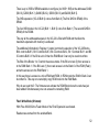
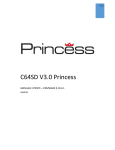
Final Expansion 3 for the VIC-20
512 KB SRAM
512 KB Flash
SD2IEC
Real Time Clock
Reset button VIC-20 (red)
Reset button FE3 (blue)
Contents
Features ....................................................................... 3
Hardware ...................................................................... 3
Software ....................................................................... 4
Third party software ...................................................... 5
Reproduction ................................................................ 6
WEB Links .................................................................... 6
Assembling ................................................................... 8
Firmware installation ..................................................... 8
Menu system handling ................................................ 10
Command set extension (FE3 wedge) ........................ 12
Reset Keys ................................................................. 12
FE3 RAM Manager ..................................................... 13
FE3 Disk Loader ......................................................... 17
FE3 Cart Loader ......................................................... 20
FE3 Utilities ................................................................ 23
FE3 Wedge................................................................. 27
LOADER files ............................................................. 34
FE3 technology and programming .............................. 42
Final Expansion Modes of use .................................... 46
2
Features
The VIC-20 Final Expansion is a universal memory expansion for the Commodore VIC-20
home computer. The FE3 is a cartridge for the expansion slot of the VIC-20. The current
version v3.2 has following features:
512 KB memory expansion of main memory
512 KB Flash memory
SD card as a mass storage device
RTC (real-time clock) and a connector for an LCD display
The Final Expansion can start any known VIC-20 software. Games and programs will be
started by a comfortable menu. The FE gives any expected environment for any software
and configures memory requirements automatically on startup.
Hardware
In addition to the SRAM (628512) and flash memory (AM29F040) chips, the PCB contains an
Atmel CPLD (ATF-1504) and an Atmel controller (ATmega644 or ATmega1284). The
controller is for the µIEC (SD2IEC) functionality. The CPLD controls the logic of the FE3 in a
single chip.
3
Software
The firmware of the FE3 is contained within the flash memory. It starts immediately after
power on and when the VIC-20 is being reset. The manual describes all features of the
firmware.
The firmware consists of two parts:
The menu system for choosing features of the FE3
The FE3 Wedge extends the command set of the VIC-20 and implements
SJLOAD/SJSAVE (Jiffy compatible load and save). Cause the integrated SD2IEC is
also Jiffy compatible, it is a benefit also with the disk loader.
The menu system offers the following features:
RAM Configuration: This menu point allows to configure any known memory
configuration of the VIC-20.
Disk loader: This menu point exists to load and execute programs on SD card or
floppy disk. The disk loader is free configurable by the User and supports any kinds of
floppy disk drives and of course the integrated SD2IEC (µIEC).
Cart loader: This menu point exists to load and execute programs directly from flash
memory. The flash provides 480KB (from 512KB) user space. You can fill this user
space with most favorite games and programs. All kind of programs are possible
(BASIC, programs, cartridges) to flash into user space.
Utilities: This are programs to update the firmware and write selected programs and
games into the flash memory.
4
Third party software
Task Switcher for FE3
A Task Switcher for the Final Expansion 3
http://sleepingelephant.com/ipw-web/bulletin/bb/viewtopic.php?p=63388#63388
RAM Disk for FE3
A RAM Disk for the Final Expansion 3
http://sleepingelephant.com/ipw-web/bulletin/bb/viewtopic.php?t=5342
5
Reproduction
The schematic of the FE is free available and the firmware is open source. Everyone can
build a FE3 themselves easily. It is possible to build a FE3 on a breadboard or a 8-Bit Baby
(see also Final Expansion v1).
There are also kits available at http://www.sinchai.de/.
WEB Links
FE3-20 available at Retro-Donald
http://www.sinchai.de/index.php?main_page=product_info&cPath=1&products_id=77
Homepage of the Final Expansion 3 (english)
http://t-winkler.net/dokuwiki/doku.php?id=en:fe3:start
Homepage of the Final Expansion 3 (german)
http://t-winkler.net/dokuwiki/doku.php?id=fe3:start
Old Homepage of the Final Expansion (english)
http://vc20final.t-winkler.net/index_en_old.html
Old Homepage of the Final Expansion (german)
http://vc20final.t-winkler.net/index_old.html
Forum-64 - Final the fe3 is a teamwork
http://www.forum64.de/wbb3/board65-neue-hardware/board284massenspeicher/board283-vc-20-final-expansion/
Forum-64 – development thread
http://www.forum64.de/wbb3/board65-neue-hardware/board2846
massenspeicher/board283-vc-20-final-expansion/28606-vc20-neoram-ram-romexpansion/
Source files & Firmware
http://vc20final.t-winkler.net/zip/
Article **Final Expansion für VC20** in the CeVi-aktuell (Ausgabe 06/2009)
http://www.c64-wiki.de/index.php/CeVi-aktuell#CeVi-Aktuell_-_06.2F2009
LOADER files (english)
http://vc20final.t-winkler.net/docu/loader_e.html
LOADER files (german)
http://vc20final.t-winkler.net/docu/loader.html
technology and programming (english)
http://vc20final.t-winkler.net/docu/internals_e.html
technology and programming (german)
http://vc20final.t-winkler.net/docu/internals.html
VC-20 Final Expansion c64-wiki.de
http://www.c64-wiki.de/index.php/VC-20_Final_Expansion
Final Expansion Rev.9 assembly instructions
http://vc20final.t-winkler.net/docu/aufbau/vc20fe3r9_aufbau.htm
Final Expansion Rev.9 assembly instructions Forum-64 thread
http://www.forum64.de/wbb3/board65-neue-hardware/board284massenspeicher/board283-vc-20-final-expansion/30960-vc20-final-expansion-aufbaurev-9/
Final Expansion Rev.10 assembly instructions
http://www.sinchai.de/index.php?main_page=page&id=10&zenid=402afa75cdfb1eaa
0cd5ff0fc57b72af
Final Expansion denial wiki
http://sleepingelephant.com/denial/wiki/index.php?title=Fe3
7
Assembling
The Final Expansion 3 is buyable as a kit:
http://www.sinchai.de/index.php?main_page=product_info&cPath=1&products_id=77
All parts must be soldered on the PCB. Look at the Assembly instructions:
http://www.sinchai.de/index.php?main_page=page&id=10
Firmware installation
After assembling the Final Expansion 3 your flash memory is empty and the controller flash
also. You need to install the FE3 firmware:
http://vc20final.t-winkler.net/zip/
After assembling the Final Expansion 3 no firmware is installed. Switching on the VIC-20 you
will see same as without connected FE3 (normal VIC-20 start message screen). You must
install the firmware to support the new hardware.
The FE3 consists of two separate parts, so you will need two different firmware:
for the FE3 memory expansion
for the integrated SD2IEC (µIEC-SD)
8
The firmware for the SD2IEC must be copied simply to the SD card. After power on, the
SD2IEC searches for an update file on the SD card and will install it automatically (if current
firmware is older).
The firmware for the memory expansion will be programmed into the flash memory. For this
is the program FE3FLASH, which is included in every firmware package.
Caution: The program FE3FLASH is necessary only if no firmware is installed or if current
firmware doesn't work properly. Otherwise the firmware can update itself using the menu
system (see FE3 Utilities, - press key F6 from main menu).
9
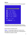
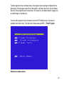
Menu system handling
The FE3 main menu appears after power on your VIC-20 and also after pressing blue reset
button. Make sure your FE3 is firmly inserted into the expansion slot of the VIC-20.
If the main menu doesn't appear, maybe the firmware is missing, see also: install firmware.
In the main menu we select one of the available features:
F1 RAM Manager: Configures your FE3 as a memory expansion.
10
F3 Disk Loader: This menu point starts a game or program from internal SD card or a
connected floppy.
F4 Help: A help screen appears which explain helpful information for using FE3 outside the
menu system.
F5 Cart Loader: This menu point starts a game or program from internal flash memory.
F6 FE3 Utilities: The utility sub menu is for erasing and writing the internal flash memory.
F7 BASIC (Wedge): Starts your VIC into BASIC with enabled (FE3 wedge) and full memory
expansion.
F8 BASIC (normal): Starts your VIC into BASIC without FE3 wedge (normal BASIC
command set) and full memory expansion.
+/- Drive #8: Changes the default device number for storage devices. Default is 8, normally
this is your internal µIEC (SD2IEC) device.
The following keys are also available in the main menu:
D: The “Credits Screen” contain the names of all people who were helpful while developing
the FE3 firmware. Thanks to all of you on the list for information, code fragments and other
helpful things, it would be more difficult if not impossible without your help.
Pressing the <CBM> key (Commodore key) while reset (or power on), the VIC-20 will start
as without inserted Final Expansion. You will see a normal startup screen, no FE3 wedge
and no memory expansion. Internal µIEC (SD2IEC) is available normally if connected to IEC
port.
Pressing the <Shift> key while reset (or power on), the VIC-20 will start without main menu
directly into the BASIC v2. The FE3 wedge is active but without memory expansion.
11
Command set extension (FE3 wedge)
The FE3 wedge extends the command set of the VIC-20.
These additional commands make it easier to use the VIC and storage devices (µIEC and
floppy disk). Aside from this FE3 wedge speed up the data transfer to Jiffy compatible
storage devices like a µIEC (SD2IEC).
Reset Keys
The FE3 has two integrated reset keys:
Blue button (former red): Big reset, concerns CPLD and VIC-20
Red button (former yellow): Small reset, concerns VIC-20 only
Why two keys? Pressing the blue button the configured memory configuration is lost. So FE3
menu always appears with the blue key, it is like after powering up. Sometimes however we
want to keep the memory configuration and want only to reset the VIC-20. This applies to
nearly all VIC game and tool cartridges. For emulating cartridges it makes sense to can set a
reset without losing the cartridge. So with the red button, the FE3 can act as a real cartridge
inserted in your VIC.
The jumper (JP7) controls the reset of the µIEC (SD2IEC) controller. If JP7 is set, SD2IEC
makes a reset same time with VIC-20. As default JP7 is open, so µIEC doesn't get a reset.
Normally a µIEC never crashes, so a reset is not necessary. After a reset the µIEC loses the
current sub directory and current image file, it return to the root directory of the SD card.
12
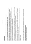
FE3 RAM Manager
Memory Expansion
The VIC-20 has in its standard configuration (unexpanded) a small main memory. Only 5KB
are free for programs (code) and data. This is the reason why a number of memory
expansion cartridges were available soon. Memory was very expensive at this time, so first
expansion had only 3KB. But soon there were other memory expansions available with a
size of 8KB and 16KB and even more.
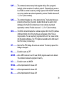
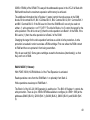
The VIC-20 changes the start address for BASIC programs video memory and if memory
expansions are active:
none
3KB
8KB
16KB
24KB
BASIC
Start
$1001
$0401
$1201
$1201
$1201
Screen
RAM
$1e00
$1e00
$1000
$1000
$1000
Color
RAM
$9600
$9600
$9400
$9400
$9400
Bytes
Free
3583
6655
11775
19967
28159
This movement of start addresses many games and programs won't run if a special
configuration is missing. So some games only run on an unexpanded VIC-20. Other games
only run with 3KB expansion and some other needs an 8KB or 16KB cartridge.
The Final Expansion 3 can be configured (by software) to emulate any combination of
memory expansion. So every known game and program can run on a FE3.
13
RAM Manager
The RAM manager will be started from the main menu of the FE3 firmware by pressing F1.
All usually needed memory models are available by selcting a menu point. Pressing the
corresponding function key will automatically configure the FE3 and start the VIC into BASIC.
Each memory model can be configured by two options:
IO Register … The <R> key toggles the IO-register option. If the option is set (X), the
software register of the FE3 are visible. If the option is reset (.), the software register of the
FE3 are disabled and a reconfiguration is not possible.
14
FE3 wedge … The <W> key toggles the wedge option. If the option is set (X), the command
extension (FE3 wedge) is active. If the option is reset (.), the standard BASIC v2 will be
started and the additional commands are not available.
The memory models 24K (F4) and 24+3K (F5) have the same start message and same
amount of free memory is reported by the BASIC interpreter. The model 24+3 enables the 3K
memory expansion in block 0. The BASIC interpreter of the VIC-20 cannot use the 3K
expansion if a 8K expansion is active. You can use the 3K expansion for assembler
programs or data blocks.
The memory model “All RAM” (F7) uses all blocks for RAM expansion including block 5. The
BASIC interpreter only can use 24K of memory expansion, the 3K RAM in block 0 and the 8K
RAM in block 5 are free for own code or data.
The memory model “Off” (F6) disables all memory expansions, the VIC-20 starts
unexpanded as without FE3 inserted. All programs and games which are designed to run on
a unexpanded VIC will run fine in this mode. Cause no memory is available for FE3 wedge,
the wedge is disabled even the option is on and your VIC starts with standard BASIC.
FE3 Wedge in LoMem
The memory model “All RAM” (F7) fills all blocks with RAM (maximal expansion). This
memory model normally is chosen because the user want do something with block 5. The
FE3 firmware and also the FE3 wedge normally run in block 5. So FE3 wedge is moved to
block 0 (low memory) in this memory model.
In block 0 is only 3KB available, so the FE3 wedge has a limited command set. Beware,
block 0 is not protected and could be overwritten. Caution: be careful with writing to memory
(POKE), don't bite the hand that feeds you … ;-)
15
Of course you could disable FE3 wedge using the option or disable it after starting BASIC
with the wedge command KILL or OFF.
The start message shows the start address of the FE3 wedge. The red message of the
wedge shows the address in parentheses. If a “B” is listed the wedge run in block 5, a 05
indicates a address in block 0:
16
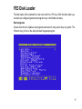
FE3 Disk Loader
The disk loader will be started from main menu with the <F3> key. With this disk loader you
can start pre configured games and programs very comfortable and easy.
Start programs
Choose from the list of games and programs and select it using cursor keys or joystick. The
<Return> key (or fire on the stick) will start the game/program.
17
If more than 17 menu entries are available, you can change the page using <F1> and <F3>
keys. The keys <F5> and <F7> selects the first or last entry of the page. This makes it
possible to navigate very fast within the menu.
Change a Disk Image
You can organize your games and programs on the SD card in subdirectories, image files
(D64, D71, D81, DNP) or M2I files. The image files are my most favorite method cause this
solution is the nearest to real diskettes and very compatible.
To change into a subdirectory or an image file you can use the disk command CD:. To leave
a subdirectory or an image file you can use CD:←. This disk command (and any other disk
command) can be behind a menu entry of the disk loader. The first menu entry on the
screenshot above shows <DIR>.., this entry bring you back to the root of the SD card, back
to the image file selection. Behind this menu entry is simply the disk command CD:←.
The menu structure of the disk loader is free configurable. I have my most important
programs packed into some image files (D64 files). Each disk loader menu comes from a
(LOADER file). The first page loaded by the disk loader is the LOADER file in the root of the
SD card, it contains links to subdirectories and/or D64 image files. Behind each of this menu
entries to select a image file or subdirectory is a simple CD: command for the SD2IEC:
18
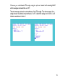
Disk loader Configuration
The Disk loader is free configurable. For this we use (LOADER files). These LOADER files
are simple files with filename “LOADER” and same structure as normal BASIC program files.
Since LOADER files are similar to BASIC programs, we can do the same well known
procedures like LOAD, SAVE and LIST. We can edit LOADER files like normal BASIC
programs, first LIST the code and edit directly on the screen, exactly as we would do with
BASIC code. We need no utility, all editing can be made by VIC-20 standard methods.
19
A LOADER file contains a whole menu list for the disk loader, all entries in one file, one or
more pages. When the disk loader is started, it loads the LOADER file from current drive into
memory and lists the first 17 entries. The LOADER file contains one chapter for each menu
entry. Each chapter contains the entry name listed in disk loader menu and one or more
commands for this menu entry. This commands can be load, configure and execute
commands. Or it can be disk commands like CD: to change into another disk image.
Everyone can make his own set of LOADER files, all connected together for navigation
between image files, to get a big collection of games and programs.
How to create LOADER files and which options are possible is documented at the section
LOADER files.
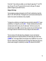
FE3 Cart Loader
The cart loader will be started from the main menu with the <F5> key. With the Cart loader
you can start games and programs stored in the flash memory of the Final Expansion.
The idea of the cart loader is, to have all most favorite games and programs in one list and
start it easily and quick.
Start programs
Choose from the list of games/programs by using the cursor keys or the joystick. By pressing
the <Return> key the game/program will be started.
20
If more than 17 menu entries available, you can switch between pages using the <F1> and
<F3> keys. The keys <F5> and <F7> set the selection bar to first and last entry of the page.
This is for fast navigation in the cart loader menu.
Add entries to Cart Loader
The cart loader menu can be configured by adding games and programs to the flash. The
size of flash memory is 512KB, it can be used 480KB for the cart loader. The remaining
memory of 32K is reserved for the firmware.
21
To add programs to the cart loader menu, the program must be already configured in the
disk loader. If this program works fine in disk loader, it will work also fine in the cart loader.
But only if this program doesn't access files. The reason is, cart loader doesn't change into
any disk image or sub directory.
You can add programs to the cart loader menu from FE3 Utilities menu, this menu is
available from main menu. The utility menu has a menu point F1 … Flash Program:
Delete Cart Loader entries
22
The 512KB big flash memory of the FE3 is writable byte for byte. But deleting is only possible
in big blocks. This is why flash memory can only deleted completely, single entries cannot
deleted.
The cart loader menu is deleted by firmware update.
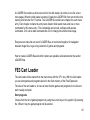
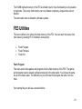
FE3 Utilities
The menu Utilities is for writing the flash memory of the FE3. You can reach this menu from
main menu by pressing F6. It includes 3 menu points:
Flash Program
Flash Firmware
Flash Info
Flash Program
This menu point writes games and programs into the flash memory of the FE3. The games
and programs must be already configured properly in the disk loader. You will see the same
list as in the disk Loader. The difference is you don't start this program but write it into the
flash.
If all running fine you will see a screen like this:
23
After flashing is completed without error you can select and start this program now from the
cart loader.
Flash Firmware
Use this menu point to update the (Firmware) of the Final Expansion. This doesn't concern
the SD2IEC firmware.
24
For this you have to copy the new firmware file to the root directory of the SD card. The
filename of the new firmware always must be fe3firmware or fe3firmware.prg. After the
firmware update a reset is triggered and it should appear the main menu.
Annotation: It must be already installed a properly working firmware to do the update in this
manner. If no firmware is installed (or not properly working …), for example after assembling
the FE3, the firmware must be written by the program fe3flash. See also Firmware
Installation.
Caution: The firmware update erases the whole flash memory! All programs and games in
the flash memory are lost and you have to reinstall it again. If a problem occur while firmware
update, the FE3 maybe won't start normally (no main menu appears). In this case you have
to install the firmware by the utility program fe3flash.
Flash Info
The Flash Info screen informs you about the allocation of the flash memory:
25
This information is useful to see how much memory is free. So you can estimate how many
programs fit in the flash memory.
26
FE3 Wedge
Functional range
The FE3 Wedge offers this features:
Extends the command set of the VIC-20
Arithmetic expressions can include binary and hexadecimal numbers
Floppy Speeder (SD card and Jiffy Floppy)
Movable into low memory
27
Floppy commands
For easy file management new commands are available (one letter shortcuts).
The argument for the shortcuts (filename) can be used either quoted or stand alone.
If a quote sign is on the 4 column (usually for a directory entry), all characters before are
ignored. This has a reason: It is for easy using directory entries as an argument, without
needs to delete a char. For example you list a directory using the shortcut $, after this you
move the cursor up to the file you want, now you can load this file simply by writing the
shortcut / and <enter> key …
$ ............... The dollar sign lists the directory of the selected drive, without overwriting the
program in memory. Letters after the $ selects files with filenames starting with
this letters.
@ ............. The “at” sign sends a command directly to the floppy drive (eg: S:, N:, I: …).
Without an argument the floppy status is read and displayed.
# ............... With this shortcut the actual device number is set or displayed. Allowed device
numbers are 8 to 15. Standard value is 8.
/ ................ Shortcut for LOAD. It loads a file with SA=0, this is for BASIC programs.
%.............. Shortcut for LOAD. It loads a file with SA=1, this is for programs at start address
in the file. If a start address is entered after the second quote sign, a cartridge file
will be loaded (SA=2). Cartridge files doesn't have a start address in the file.
28
← ............. The <left arrow> is a shortcut for SAVE. Optionally a start- and end address can
be entered. If the file already exists on the disk, the wedge ask what to do, replace or update. On “update” always two versions of the file are saved. The
older version of the file has a filename prefix, the ' character is used to mark the
older file version.
> ............... Shortcut for the VERIFY command. The file will be compared with the memory, if
same a “OK” is displayed otherwise a VERIFY ERROR appears.
Other commands
These commands are available only in direct mode, not in RUN mode within a BASIC code.
The commands can be entered in short form like all other commands by entering the last
letter shifted.
, ................... The comma is a command for number conversion (mini calculator). All
arguments are seen as a numeric expression and calculated. The result will be
displayed in different notations: decimal, hexadecimal, binary and as an ASCII
string
RESET ........ It is like a real VIC reset (red reset key). Other than a SYS64802 it emulates a
real reset necessary for some games (mostly cartridge games in block 5) to run
properly.
BLK ............ This command makes the same as BLKP. it is only for compatibility reasons.
29
BLKP .......... This command protects memory blocks against writing. After a program is
loaded in a block sometimes it is useful to protect it. Protected blocks seems to
be a ROM, the content is read only, writing is ignored. After the BLKP command
one or more numbers are entered separated by commas. Possible values are 0,
1, 2, 3 or 5 (block numbers).
BLKD .......... This command disables one or more memory blocks. The disabled blocks are
physically removed, like not existent. Disabled blocks can be used by other
cartridges. After the BLKD command one or more numbers are entered
separated by commas. Possible values are 0, 1, 2, 3 or 5 (block numbers).
NOIO ........... The NOIO command disables the 2 software register within the CPLD (address
39938 and 39939) of the FE3. After this are configuration of the FE3 is no
longer possible. You can use this for programs which won't run, cause it writes
into this register addresses. The FE3 register are available until a hard reset of
the CPLD occurs (red reset key).
OFF............. Switch off the FE3 Wedge. All vectors are restored. The memory space of the
Wedge is free again.
KILL ............ Exactly the same as OFF
UNNEW ...... After a NEW command or a VIC reset, BASIC programs seems to be deleted.
This command restores the program in memory.
OLD ............ Exactly the same as UNNEW.
RENUM ....... will be implemented with release r021
FIND ........... will be implemented with release r021
DEL ............. will be implemented with release r021
30
LOAD and SAVE
Beside the accelerated access to files the FE3 has more benefits:
Display of start- and end address while loading and saving
Loading of files without start address (cartridge files) by entering a SA=2
Loading of files with a given start address by using a SA=1 and a additional argument
(start address)
Saving of files with a given start- and end address
Examples:
LOAD “CARTIDGE”,8,2,$A000
LOAD “CARTRIDGE”,8,1,$2000
SAVE “CARTRIDGE”,8,1,$2000,$4000
Formula evaluation
The formula evaluation is extended (also within running BASIC programs) by binary and
hexadecimal numbers. This can be used everywhere, even for assignments, PRINT
commands or any parameters for commands. The different numerations can be used mixed
in any combination.
31
Hexadecimal numbers are preceded by a dollar sign ($). The numbers must have 2 or 4
digits. Only integers are allowed. Usable digits are 0 to 9 and A to F.
Binary numbers are preceded by a percent sign (%). The numbers must have 4, 8, 12 or 16
digits. Only integers are allowed. Usable digits are 0 and 1.
Examples:
A = 7 + $2C * 9
PRINT $2F - 14
POKE $A077,$5A
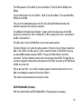
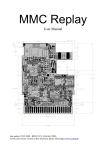
Floppy speeder
The accelerated access to files is made by Jiffy compatible procedures (SJLOAD). Jiffy DOS
is the most favored serial speeder. LOAD and SAVE are speeded up by 6 to 10 times to
normal IEC procedures. The SD2IEC is much faster than a normal Jiffy floppy especially for
small files. The reason is SD card doesn't have a motor startup delay and also no sector
search delay.
LOAD 48
blocks
SAVE 48
blocks
normal
1541
21,8s
Jiffy
1541
6,5s
SD2IEC
26,4s
16,1s
7,5s
2,2s
32
But not only LOAD and SAVE are sped up by the FE3 wedge, all data access is accelerated
if the kernel jmp table is used. This is cause FE3 wedge changes all of IEC concerning
vectors of the VIC-20: CHKIN,CKOUT,BSOUT,BASIN,CLALL,CLRCH
The speeder works with all Jiffy compatible floppy drives, including the internal µIEC
(SD2IEC). Normal floppy drives (not Jiffy powered) run fine but only with normal (slow)
speed.
If the wedge is running in low memory (block 0), floppy speeder is disabled. This small
version of the FE3 wedge doesn't have this feature, because only 3K RAM is available.
Movable into low Mem
The FE3 Wedge normally uses an address range at $B (upper side of block 5). Block 5
cannot used by BASIC v2, so this is a good location for the wedge.
By choosing full RAM in the RAM manager (F1, F7) whole block 5 will be usable RAM. In this
case a small version of the FE3 wedge is copied into the low memory (3K expansion area at
block 0). This version of the wedge has a limited command set, cause limited space in block
0.
33
LOADER files
The purpose of the Loader files:
The loader file is needed by FE3 Disk Loader which is always looking for the file "LOADER"
in the current directory. Disk Loader interprets these script files saved in the form of VIC
Basic prg files but not actually executable Basic Programs.
Using these scripts you can select and easily start any games and / or programs with no
programming skills - once you have set them up or downloaded them ;-)
Once the FE3 Disk Loader can load a program it can also be added to the FE3 Flash Rom.
The Cart Utilities (F6) Flash Program (F3) makes use of the Loader scripts to package the
files and commands into an executable block of code before flashing to the rom.
Structure of the file "LOADER"
The LOADER file consists of one or several sections. Each section is presented as a menu
item in Disk loader. A section consists of:
a name: each section begins with a name in the menu displayed in Disk loader
one or more instructions
comment lines may be added optionally
names begin and end with a quotation mark (")
Instruction lines always begin with a plus sign (+)
comment lines begin with a colon (:)
34
The section name will begin and end simply with a quotation mark ("). The name can be up
to 20 characters and may include any special characters. If the name is longer than 20
characters, Disk loader shows only the first 20. Control characters are ignored.
The instructions in a section are performed when the user activates the menu item in Disk
Loader by pressing the RETURN key or the joystick FIRE button. Instruction lines always
begin with a plus sign (+).
The sequence of instructions will be chosen by Disk Loader as follows:
Disk loader always executes:
first LOAD instructions,
then BLK and IO instructions, and
last RUN, SYS or RESET commands.
The order in the script is only relevant for commands of the same sub type e.g. multiple
LOAD commands.
The optional comment lines begin with a colon (:). The comment line can be blank (Section
divider) or contain any text strings. A comment line does not end the section. Comment lines
are optional and can therefore be omitted entirely.
A section ends with the end of the script file or the beginning of a new section.
Instructions
The following statements are recognized by Disk loader and interpreted:
Load statement : Loads a file from a floppy disk or SD
Disk Command : Sends a command to the SD2IEC or to a floppy.
35
BLK, BLKP, BLKD : Instructions for configuring the FE3 hardware - block write
protect or disable.
NOIO : Instructions for configuring the hardware FE3 – Hide FE3 IO registers.
RESET : Instruction to restart the VIC-20 (Soft Reset)
SYS : Starts a machine code program at the given address (in hexadecimal!)
RUN : Starts a BASIC program
RELOAD : Restart command to the File Loader (runs the Loader script in the current
directory)
The Load Statement loads a file from the SD card or from a floppy. Several load instructions
can be sequenced if for example games with several parts exist. In the simplest case the
statement can consist of only one file name. The file name consists of up to 16 characters
and is enclosed in quotation marks.
An optional type can be specified and appended to the load command.
File types are B (BASIC), P (PROGRAM) and C (cartridge). These correspond to the
secondary address (0,1,2) of the modified LOAD command in FE3 Wedge.
The file type BASIC is automatically always loaded at the address where the BASIC memory
starts (secondary address 0). This address may vary depending on memory configuration.
The file type PROGRAM is always loaded at the address that is contained in the file (the first
two bytes). This corresponds to a LOAD with secondary address 1. The load address can
optionally be overridden - See - optional load address.
The file type CARTRIDGE is for files without a load address. These files are often
recognized by the exact file size of 4K (4096), 8K (8192) or 16K (16384). This file type
requires always an indication of the load address!
36
The load statement may also have an optional load address appended. For file type C, the
load address is always required. The load address must always be hexadecimal, starting
with a $ sign.
The load commands are executed in the order given. If you intend to load something into the
cassette buffer from $330 onwards, this must be the last section! This is because the Disk
Loader uses this area of memory.
Examples of load commands:
+"MOONPATROL"
+"EXBASIC2",C,$A000
+"AUSTRO COMP",B
+"VICMON",P,$3000
A Disk Command starts with the AT sign (@) followed by the actual command in quotes.
You can send any possible commands to the target device (SD2IEC or floppy) provided the
device understands the command.
The main application of the Disk Command may be to change the current directory or the
current disk image (D64). We can comfortably navigate the SD card this way. You do not
have to have all the games in a single huge list, it can be arranged as you wish.
37
As stated any disk command is possible. You can for example erase a high score table with
an "S" command or a high score table could be saved by the C (Copy) or R (Rename). This
is limited only by your imagination.
Disk Commands can be used before or after a Load command.
The configuration of the FE3 is only necessary for the specific games and programs. If a
game or program runs without running a configuration you can do without these instructions.
There are games and programs that do not run by normal load and start. The program does
not find the necessary environment and can / will therefore not run. By configuring the
hardware, FE3 can simulate every possible memory expansion hardware and run every
known program except for those which require very specific hardware modules e.g. 80
character card, IEEE-488 card, RS-232/Modem cards etc.
The commands BLK, BLKD and BLKP configure the memory. The block numbers can follow
the command in any order: 0,1,2,3,5. All five memory blocks are enabled by default and must
be turned off to get smaller or unexpanded memory configurations.
The block numbers correspond to the physical blocks of the VIC-20:
0 = Block 0 ($ 0400 - $ 0FFF)
1 = Block 1 ($ 2000 - $ 3FFF)
2 = Block 2 ($ 4000 - $ 5FFF)
3 = Block 3 ($ 6000 - $ 7FFF)
5 = Block 5 ($ A000 - $ BFFF)
38
The blocks can be disabled and protected against overwrite individually:
BLKD disable Block
BLKP protect Block (BLK is equal to BLKP for backward compatibility)
Inactive blocks are quasi-nonexistent. The FE3 acts like it is not populated in the
corresponding range of addresses. Another cartridge could be used with FE3 in a multi slot
expansion in the address blocks that have been disabled.
Blocks with write protection act like a ROM or EPROM. These blocks can only be read from,
write commands are ignored.
The command NOIO hides the registers of FE3. After this is set, further configuration of the
FE3 is no longer possible and the corresponding IO area is free. A hardware reset puts the
FE3 back to the original state and allows reconfiguration.
Examples of configurations:
+BLK 1,3
+BLKD 0,1,2,3
+BLKP 0,1,2,3,5
+NOIO
Loaded games or programs must be started, the commands RESET, RUN and SYS are
available to do this. One of the three commands is used depending on the requirements of
the program.
39
After the Disk Command to change the directory or the disk image, the command RELOAD
must be used. In the new directory or the new D64 Image has to be another LOADER file
that must be loaded by the Disk Loader.
Without the RELOAD command the Disk Loader works with the wrong file and thus the
wrong LOADER instructions. The statements cannot be executed because for example, the
file to load is no longer accessible in the directory.
Example 1 of a LOADER file:
10 "HW Demo unexpanded"
20 +"hello world",b
30 +blk 0,1,2,3,5
40 +run
50 :
60 "HW Demo 3K"
70 +"hello world",b
80 +blk 1,2,3,5
90 +run
100 :
110 "HW Demo 8K"
120 +"hello world",b
130 +blk 0,2,3,5
140 +run
150 :
160 "HW Demo 16K"
40
170 +"hello world",b
180 +blk 0,3,5
190 +run
200 :
210 "HW Demo 24K +8 +3"
220 +"hello world",b
230 : no blk command
240 +run
250 :
41
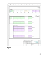
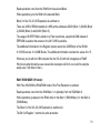
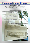
FE3 technology and programming
The Final Expansion contains 512KB SRAM and 512KB Flash memory. In order to access
the expanded memory one has to enable it sequentially. This is due to the constraints of the
address range of the 6502 processor which can only see 64KB at a time. On the VIC-20 the
free address space is constrained to 4 x 8KB + 3KB (See memory map):
42
Registers:
43
The Final Expansion has 2 registers in order to configure it through software. The registers
are accessed like memory addresses and can be read from (PEEKed) and written too
(POKEed). The registers have 8 bits as for other memory addresses. After a Hard Reset or
after switching on the VIC-20, both registers contain Zero.
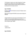
Register 1 39938 ($9C02):
With Register 1 the MODE of the Final Expansion can be selected. The Register is located at
address 39938 ($9c02).
Values are written to the register With POKE 39938,x. Values are read from the Register with
PEEK(39938).
The highest 3 bits (Bit 5,6 and 7) control the usage mode of the Final Expansion. The lowest
5 bits (Bit 0,1,2,3 and 4) provide additional information the selected mode of use. It is
possible to build a value for the register using AND and OR logic and then poke the resulting
number to the Register. (Register 1: MMMIIIII).
M - Mode of Use
I - Additional Information
Register 2 39939 ($9C03):
44
With register 2 the RESOURCES of Final Expansion can be enabled or disabled. The
Register is located at 39939 ($9c03). Values are written to the register With POKE 39939,Y.
Values are read from the Register with PEEK(39939).
The VIC-20 has 5 free address ranges (memory blocks). The Final expansion can make
these 5 blocks available independently. This means the Final Expansion memory can be
made available in one or more blocks to the VIC-20 (Banking)
The lower 5 bits (Bit 0,1,2,3 and 4) of Register 2 control the visibility of the 5 memory blocks
in the VIC-20. A 0 switches the relevant block on and a 1 switches it off. The configuration of
individual blocks is needed to enable compatibility with other expansion modules.
The highest bit (Bit 7) of Register 2 controls the visibility of the Registers themselves. A 0
makes the Registers visible, a 1 hides the Registers (Deactivates the Registers)
ATTENTION: if the Registers are deactivated then it is no longer possible for the software to
alter the memory configuration. Only after a Reset will the Register become visible again.
Disabling these Registers is used to prevent new software from altering the configuration of
the Final Expansion without intention. With this facility the compatibility of the Final
Expansion with any conceivable software is ensured.
Bit 0 ... Visibility of the VIC-20 memory block 0 (Blk0 - $0400-$0FFF)
Bit 1 ... Visibility of the VIC-20 memory block 1 (Blk1 - $2000-$3FFF)
Bit 2 ... Visibility of the VIC-20 memory block 2 (Blk2 - $4000-$5FFF)
45
Bit 3 ... Visibility of the VIC-20 memory block 3 (Blk3 - $6000-$7FFF)
Bit 4 ... Visibility of the VIC-20 memory block 5 (Blk5 - $A000-$BFFF)
Bit 5 ... 1: invert A13
Bit 6 ... 1: invert A14
Bit 7 ... Visibility of IO-3 (Register 1 und 2)
Banking:
In order to access the full memory of the Final Expansion, the memory must be switched on
in stages. In order to achieve this, a number of modes are available for use in order to cover
every requirement.
Final Expansion Modes of use:
START MODE (000zzzzz):
After a reset with the red button or after initial power on, all the bits in the register are set to
zero, in this way the FE is always in START MODE after a reset With POKE 39938,0 the
START MODE can be activated from software.
Write operations to the FE memory go to RAM in Bank 1.
The 0 Block of the VIC-20 (3k expansion) is disabled.
The START MODE of Final Expansion is provided for maximum compatibility with other
modules. In order to avoid possible incompatibility with other expansion modules, The Final
Expansion controls only Block 5 (Memory range $A000 - $BFFF). Block 5 must be active,
otherwise the firmware of the Final Expansion itself cannot be automatically started.
46
Because the Final Expansion in START MODE only uses block 5, one can simply deactivate
the FE by disconnecting the BLK5 circuit path. (e.g. with a switch). N.B. This would require a
modification to the Final Expansion or the VIC-20 expansion port.
The registers are deactivated in START MODE, the Lockbit serves as a control for this.
The lockbit functions only in START MODE in order to avoid incompatibility with other
modules that may use the same addresses as Final Expansion for registers.
The lockbit can be cleared via a POKE to Block 5. A PEEK resets the lockbit again.
This way programs in Block 5 cannot write to an FE register as long as the FE is in START
MODE.
In START MODE only block 5 is controlled.
Read operations are from the Flash at address $6000 (Flash Block 3, highest block of the
first 32k bank - Bank 0).
Write operations always go to SRAM. This way the whole firmware can be simply copied to
SRAM.
Write operations to Block 5 go to SRAM address $E000 (SRAM Block 7, highest block of the
second 32k bank - Bank 1).
If the SRAM 1 mode is switched to, the SRAM Block 7 lies exactly in Block 5 of the VIC-20.
SUPER ROM MODE (010zzzzz):
With Poke 39938,64 the flash memory of the Final Expansion is enabled.
Read operations come from the ROM (Flash) i.e. from the selected Bank.
47
Write operations go to the RAM in Bank 1.
The Block 0 of the VIC-20 (3k expansion) is enabled.
The 512KB of the Flash are divided into 16 pages of 32KB, any one of which can be selected
for access. These 32KB are further divided into 8KB pieces and are assigned to the
addresses $2000 (BLK 1), $4000 (BLK 2), $6000 (BLK 3) and $A000 (BLK 5).
The additional information in the Register (zzzzz) select the relevant 32KB block of the Flash
memory,
In 512KB there are 16 x 32KB pages. The additional register values can therefore take the
values 0 to 15.
Readers will notice that the additional register information can hold 5 bits or 32 values.
Correct, the Final Expansion can also address 1MB chips. However, these are not available
to buy in DIL packages, therefore this cannot be used.
RAM 1 MODE (100zzzzz):
With POKE 39938,128 the SRAM of the Final Expansion is activated.
Read operations are always from RAM Bank 1.
Write operations go to RAM Bank 1 or optionally to Bank 2.
The Block 0 of the VIC-20 (3K Expansion) is switched on. The Bit 0 of Register 1 controls the
write protection. There is up to 35KB of SRAM available to configure (4 x 8KB + 3KB) at the
addresses $0400 (BLK 0), $2000 (BLK 1), $4000 (BLK 2), $6000 (BLK 3) and $A000 (BLK
5). The 3KB expansion (VIC-20 BLK 0) comes from Bank 0 (The first 32KB in SRAM) of the
SRAM. The four 8KB blocks in the VIC-20 (BLK 1 - BLK 5) come from Bank 1 (The second
48
32KB in SRAM) of the SRAM. This way all the addressable space in the VIC-20 is filled with
RAM and therefore the maximum expansion with memory is achieved.
The additional information bits in Register 1 (zzzzz) control the write access to the RAM
blocks. Bit 4 controls BLK 5, Bit 3 Controls BLK 3, Bit 2 Controls BLK 2, Bit 1 Controls BLK 1
and Bit 0 Controls BLK 0. If the Bit is set to 0 then the RAM Block 0 can only be read not
written. (1: write protection = on??? Off??? The bits for Blocks 1 to 5 control the target for the
write operation. If the bit is not set (0) then the write operation is to Bank 1 of the RAM. If the
Bit is set to (1) then the write operation is to Bank 2 of the RAM.
Changing the target for the write operation functions as a kind of write protection. A write
protection is needed in order to emulate a ROM cartridge. First one writes the ROM content
to RAM and then one protects it from being overwritten.
Why do we need this? Some game cartridges overwrite themselves (intentionally), so that
they won't run in RAM.
RAM 2 MODE (110zzzzz):
With POKE 39938,192 RAM Mode 2 of the Final Expansion is activated.
Read operations come from the RAM Bank 1 or optionally from Bank 2.
Write operations are always to RAM Bank 1.
The Block 0 of the VIC-20 (3K Expansion) is switched on. The Bit 0 of Register 1 controls the
write protection. There is up to 35KB of SRAM available to configure (4 x 8KB + 3KB) at the
addresses $0400 (BLK 0), $2000 (BLK 1), $4000 (BLK 2), $6000 (BLK 3) and $A000 (BLK
5).
49
The 3KB expansion (VIC-20 BLK 0) comes from Bank 0 (The first 32KB in SRAM) of the
SRAM.
The four 8KB blocks in the VIC-20 (BLK 1 - BLK 5) come from Bank 1 (The second 32KB in
SRAM) of the SRAM.
This way all the addressable space in the VIC-20 is filled with RAM and therefore the
maximum expansion with memory is achieved.
The additional information bits in Register 1 (zzzzz) control the write access to the RAM
blocks. Bit 4 controls BLK 5, Bit 3 Controls BLK 3, Bit 2 Controls BLK 2, Bit 1 Controls BLK 1
and Bit 0 Controls BLK 0.
If the Bit is set to 0 then the RAM Block 0 can only be read not written.
The bits for Blocks 1 to 5 control the write operation. If the bit is not set (0) then it reads from
Bank 1 of the RAM. If the Bit is set to (1) then it reads from Bank 2 of the RAM. In this way
you have 64KB available (instead of 32KB). This way the RAM in Bank 2 cannot be
overwritten. The Ram in Bank 2 functions with write protection (like ROM). Through this you
can leave a program running without losing access to the RAM, one has a sort of RAM under
a ROM, like in the C64.
Why do we need this? : one could for example program a machine code monitor to run in
Bank 2 and display the contents of the whole of Bank 1.
This monitor would need almost no memory for itself.
SUPER RAM MODE (101zzzzz):
With Poke 39938,160 the SUPER RAM MODE of Final Expansion is activated.
50
Read operations come from the RAM from the selected Bank.
Write operations go to the RAM in the selected Bank.
Block 0 of the VIC-20 (3K Expansion) is switched on.
There are 32KB of SRAM enabled (4 x 8KB) at the addresses $2000 (Block 1), $4000 (Block
2), $6000 (Block 3) and $A000 (Block 5).
The usage of SUPER RAM is similar to a Flash read mode, except that RAM instead of
EEPROM is used so that access to the full 512KB is possible.
The additional information in the Register (zzzzz) selects the 32KB Block of the SRAM.
In 512KB one has 16 x 32KB Blocks. The additional information can take the values 0 to 15.
What can you do with an 8 Bit computer like the VIC-20 with half a megabyte of RAM?
Who knows what innovative uses resourceful developers will find, one could for example
easily save 3 full disks in there ...
RAM / ROM MODE (011zzzzz):
With Poke 39938,96 the RAM/ROM mode of the Final Expansion is enabled.
Read operations come from the RAM Bank 1 or optionally from the ROM Bank 0.
Write operations go always to the RAM, either in the Bank 1 (RAM Mode) or in the Bank 2
(ROM Mode).
The Block 0 of the VIC-20 (3K Expansion) is switched on.
The Bit 0 of Register 1 controls the write protection.
51
There is up to 35KB of SRAM available to configure (4 x 8KB + 3KB) at the addresses $0400
(BLK 0), $2000 (BLK 1), $4000 (BLK 2), $6000 (BLK 3) and $A000 (BLK 5).
The 3KB expansion (VIC-20 BLK 0) comes from Bank 0 (The first 32KB in SRAM) of the
SRAM.
The four 8KB blocks in the VIC-20 (BLK 1 - BLK 5) come from Bank 1 (The second 32KB in
SRAM) of the SRAM.
This way all the addressable space in the VIC-20 is filled with RAM and therefore the
maximum expansion with memory is achieved.
The additional information in Register 1 (zzzzz) controls the selection of the VIC-20 Blocks.
Bit 4 controls BLK 5, Bit 3 Controls BLK 3, Bit 2 Controls BLK 2, Bit 1 Controls BLK 1 and Bit
0 Controls BLK 0. If the Bit is set to 0 then the RAM Block 0 can only be read not written.
The Bits of the Blocks 1 to 5 control the access mode. If the Bit is not set (0) then access is
to the RAM Bank 1. If the Bit is set (1) then read access is to the Bank 0 of the ROM (Flash)
and write access is to the RAM Bank 1.
In this way there is access to a mix of RAM and ROM. In ROM mode the RAM in Bank 2 can
be written to. This way one can simply copy ROM code into the RAM Bank.
Why do we need this?: The firmware can activate the ROM Block where the code has just
been added. Simultaneously one can access the remaining RAM.
Flash Write Mode (001zzzzz):
With Poke 39938,32 the FLash Mode of the Final Expansion is activated.
Read access comes from the enabled Bank.
52
Write access goes to the ROM (Flash) in the selected Bank.
The Block 0 of the VIC-20 (3k Expansion) is enabled.
In this mode it is possible to examine and erase the Flash memory. In order to do this the
special command sequence must be followed as prepared by the manufacturer of the Flash
memory (See AM29F040 Data Sheet).
The Banking follows the same method as Super ROM mode.
The FE Firmware Flasher (fe3flash) uses this method.
53