1
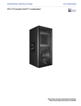
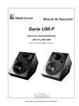
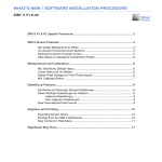
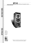
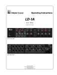
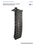
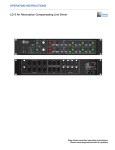
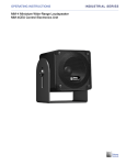
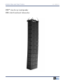
OPERATING INSTRUCTIONS
M3D™ Line Array Loudspeaker
M3D-Sub Directional Subwoofer
M SERIES
DECLARATION
OF
CONFORMITY ACCORDING TO ISO/IEC GUIDE AND EN 45014
The Manufacturer:
Meyer Sound Laboratories, Inc.
2832 San Pablo Avenue
Berkeley, California 94702-2204, USA
Declares that the product: M3D™, M3D-Sub
Conforms to the following Product Specifications
Safety:
EN60065: 1998
IEC60065: 1998
EMC:
EN55103-1: 1997 emission(1)
EN55103-2: 1997 immunity(2)
This device complies with the requirements of the Low Voltage
Directive 73 / 23 / EEC and the EMC Directive 89 /336 / EEC.
This device also complies with EN 55103-1 & -2. Operation is
subject to the following two conditions:
(1) this device may not cause harmful interference, and
(2) this device must accept any interference received, including
interference that may cause undesired operation.
Environmental Specifications For Meyer Sound Electronics
Products:
Operating Temperature
0˚C to + 45˚C
Nonoperating Temperature
<-40˚C or > +75˚C
Humidity
to 95% at 35˚C
Operating Altitude
to 4600 m (15,000 ft)
Nonoperating Altitude
to 6300 m (25,000 ft)
Shock
30g 11 msec half-sine on each
of 6 sides
Vibration
10Hz to 55Hz (0.010m
peak-to-peak excursion)
3K59 COMMERCIAL
AUDIO SYSTEM
Made by Meyer Sound Laboratories
Berkeley, California USA
European Office:
Meyer Sound Lab. GmbH
Carl Zeiss Strasse 13
56751 Polch, Germany
Office of Quality Manager
Berkeley, California USA July 19, 2002
COPYRIGHT
® 2002 Meyer Sound. All rights reserved.
M3D Line Array Loudspeaker Operating Instructions.
The contents of this manual are furnished for informational purposes only, are subject to change without notice, and should not be
construed as a commitment by Meyer Sound Laboratories, Inc. Meyer Sound assumes no responsibility or liability for any errors or
inaccuracies that may appear in this manual.
Except as permitted by applicable copyright law, no part of this publication may be reproduced, stored in a retrieval system, or
transmitted, in any form or by any means, electronic, mechanical, recording or otherwise, without prior written permission from Meyer
Sound.
M3D™, TruPower™, RMS™, BroadbandQ™, MAPP Online™ and REM™ are trademarks of Meyer Sound. SIM® and QuickFly® are registered
trademarks of Meyer Sound (Reg. U.S. Pat. & Tm. Off.). All third-party trademarks mentioned herein are the property of their respective
trademark holders.
Printed in the U.S.A.
Part Number: 05.105.022.01 Rev. A (08/02)
SYMBOLS USED
These symbols indicate important safety or operating features in this booklet and on the chassis.
!
Dangerous voltages: risk of electric
shock
Important operating instructions
Frame or chassis
Protective earth ground
Pour indiquer les risques résultant
de tensions dangereuses
Pour indequer important
instructions
Masse, châssis
Terre de protection
Zu die gefahren von gefährliche
spanning zeigen
Zu wichtige betriebs-anweisung
und unter-haltsanweisung zeigen
Rahmen oder chassis
Die schutzerde
Para indicar voltajes peligrosos.
Instrucciones importantes de
funcionamiento y/o manteniento
Armadura o chassis
Tierra proteccionista
IMPORTANT SAFETY INSTRUCTIONS
1. Read these instructions.
2. Keep these instructions.
3. Heed all warnings.
4. Follow all instructions.
11. Only use attachments/accessories specified by Meyer
Sound.
12. Use only with the caster rails or rigging specified by Meyer
Sound, or sold with the loudspeaker. Handles are for
carrying only.
5. Do not use this loudspeaker near water.
6. Clean only with dry cloth.
7. Do not block any ventilation openings. Install in accordance
with Meyer Sound's installation instructions.
8. Do not install near any heat sources such as radiators, heat
registers, stoves, or other apparatus that produce heat.
9. Do not defeat the safety purpose of the grounding-type
plug. A grounding type plug has two blades and a third
grounding prong. The third prong is provided for your
safety. If the provided plug does not fit into your outlet,
consult an electrician for replacement of the obsolete
outlet.
10. Protect the power cord from being walked on or pinched
particularly at plugs, convenience receptacles, and the point
where they exit from the loudspeaker. The AC mains plug or
appliance coupler shall remain readily accessable for
operation.
!
CAUTION: Rigging should only be done by
experienced professionals.
13. Unplug this loudspeaker during lightning storms or when
unused for long periods of time.
14. Refer all servicing to qualified service personnel. Servicing
is required when the loudspeaker has been damaged in any
way, such as power-supply cord or plug is damaged, liquid
has been spilled or objects have fallen into the loudspeaker,
the loudspeaker has been exposed to rain or moisture, does
not operate normally, or has been dropped.
15. This loudspeaker provides protection against direct sprays
of water up to 15 degrees from vertical. Rating IP42 in
accordance with IEC 60529.
SAFETY SUMMARY
English
Deutsch
– To reduce the risk of electric shock, disconnect the
loudspeaker from the AC mains before installing audio
cable. Reconnect the power cord only after making all signal
connections.
– Connect the loudspeaker to a two-pole, three-wire
grounding mains receptacle. The receptacle must be
connected to a fuse or circuit breaker. Connection to any
other type of receptacle poses a shock hazard and may
violate local electrical codes.
– Do not install the loudspeaker in wet or humid locations
without using weather protection equipment from Meyer
Sound.
– Do not allow water or any foreign object to get inside the
loudspeaker. Do not put objects containing liquid on or near
the unit.
– To reduce the risk of overheating the loudspeaker, avoid
exposing it to direct sunlight. Do not install the unit near
heat-emitting appliances, such as a room heater or stove.
– This loudspeaker contains potentially hazardous voltages.
Do not attempt to disassemble the unit. The unit contains no
user-serviceable parts. Repairs should be performed only
by factory-trained service personnel.
– Um die Gefahr eines elektrischen Schlages auf ein Minimum
zu reduzieren, den Lautsprecher vom Stromnetz trennen,
bevor ggf. ein Audio-Schnittstellensignalkabel
angeschlossen wird. Das Netzkabel erst nach Herstellung
aller Signalverbindungen wieder einstecken.
– Der Lautsprecher an eine geerdete zweipolige DreiphasenNetzsteckdose anschließen. Die Steckdose muß mit einem
geeigneten Abzweigschutz (Sicherung oder
Leistungsschalter) verbunden sein. Der Anschluß der
unterbrechungsfreien Stromversorgung an einen anderen
Steckdosentyp kann zu Stromschlägen führen und gegen die
örtlichen Vorschriften verstoßen.
– Der Lautsprecher nicht an einem Ort aufstellen, an dem sie
mit Wasser oder übermäßig hoher Luftfeuchtigkeit in
Berührung kommen könnte.
– Darauf achten, daß weder Wasser noch Fremdkörper in das
Innere den Lautsprecher eindringen. Keine Objekte, die
Flüssigkeit enthalten, auf oder neben die
unterbrechungsfreie Stromversorgung stellen.
– Um ein Überhitzen dem Lautsprecher zu verhindern, das
Gerät vor direkter Sonneneinstrahlung fernhalten und nicht
in der Nähe von wärmeabstrahlenden Haushaltsgeräten (z.B.
Heizgerät oder Herd) aufstellen.
– Im Inneren diesem Lautsprecher herr-schen potentiell
gefährliche Spannungen. Nicht versuchen, das Gerät zu
öffnen. Es enthält keine vom Benutzer reparierbaren Teile.
Reparaturen dürfen nur von ausgebildetem
Kundenienstpersonal durchgeführt werden.
Français
– Pour réduire le risque d’électrocution, débrancher la prise
principale de l’haut-parleur, avant d’installer le câble
d’interface allant à l’audio. Ne rebrancher le bloc
d’alimentation qu’après avoir effectué toutes les
connections.
– Branchez l’haut-parleur dans une prise de courant à 3
dérivations (deux pôles et la terre). Cette prise doit être
munie d’une protection adéquate (fusible ou coupe-circuit).
Le branchement dans tout autre genre de prise pourrait
entraîner un risque d’électrocution et peut constituer une
infraction à la réglementation locale concernant les
installations électriques.
– Ne pas installer l’haut-parleur dans un endroit où il y a de
l’eau ou une humidité excessive.
– Ne pas laisser de l’eau ou tout objet pénétrer dans l’hautparleur. Ne pas placer de r´cipients contenant un liquide sur
cet appareil, ni à proximité de celui-ci.
– Pour éviter une surchauffe de l’haut-parleur, conserver-la
à l’abri du soleil. Ne pas installer à proximité d’appareils
dégageant de la chaleur tels que radiateurs ou appareils de
chauffage.
– Ce haut-parleur contient des circuits haute tension
présentant un danger. Ne jamais essayer de le démonter. Il
n’y a aucun composant qui puisse être réparé par
l’utilisateur. Toutes les réparations doivent être effectuées
par du personnel qualifié et agréé par le constructeur.
Español
– Para reducir el riesgo de descarga eléctrica, desconecte de
la red de voltaje el altoparlante antes de instalar el cable de
señal de audio. Vuelva a conectar la alimentacion de voltaje
una vez efectuadas todas las interconexiones de
señalizacion de audio.
– Conecte el altoparlante a un tomacorriente bipolar y trifilar
con neutro de puesta a tierra. El tomacorriente debe estar
conectado a la protección de derivación apropiada (ya sea
un fusible o un disyuntor). La conexión a cualquier otro tipo
de tomacorriente puede constituir peligro de descarga
eléctrica y violar los códigos eléctricos locales.
– No instale el altoparlante en lugares donde haya agua o
humedad excesiva.
– No deje que en el altoparlante entre agua ni ningún objeto
extraño. No ponga objetos con líquidos encima de la unidad
ni cerca de ella.
– Para reducir el riesgo de sobrecalentamiento, no exponga la
unidad a los rayos directos del sol ni la instale cerca de
artefactos que emiten calor, como estufas o cocinas.
– Este altoparlante contiene niveles de voltaje peligrosos en
potencia. No intente desarmar la unidad, pues no contiene
piezas que puedan ser repardas por el usuario. Las
reparaciones deben efectuarse únicamente por parte del
personal de mantenimiento capacitado en la fábrica.
CONTENTS
Introduction
AC Power
AC Power Distribution
Voltage Requirements
Current Requirements
Power Connector Wiring Conventions
Safety Issues
Audio Input
Amplification and Protection Circuitry
M3D Interconnections
M3D-Sub Interconnections
The TruPower™ Limiting System
M3D TPL Limiters
M3D Peak Limiter
M3D-Sub TPL Limiters
M3D-Sub Excursion Clamp
Fans and Cooling System
Using and Replacing the Rain Hood
Opening the Rain Hood
Removing the M3D/M3D-Sub Amplifier
Replacing the M3D/M3D-Sub Amplifier
How Do Line Arrays Work?
Hybrid Line Arrays
Adjusting a Line Array’s Coverage
Cabling
Using the M3D-Sub With the M3D Line Array Loudspeaker
Driving the M3D-Sub
SIM® System II
Applications
Measurement Modes and Features
Meyer Sound MAPP Online™
RMS™ (Remote Monitoring System)
Monitor Displays
Appendix A - M3D Line Array Specifications
Appendix B - M3D-Sub Directional Subwoofer Specifications
Contact Information
1
2
2
2
3
3
5
5
6
6
7
7
7
8
8
8
8
9
9
10
10
10
11
11
14
14
14
17
17
17
18
18
18
20
23
26
Operating Instructions
M3D™ Line Array
INTRODUCTION
The M3D Line Array is a part of the Meyer Sound M Series,
which is a fully integrated line of loudspeakers that brings
singular advantages to real-world applications.
The M3D Line Array, shown in Figure 1, draws upon
classic linear array principles and is a hybrid system
using advanced engineering to optimize line array
performance for consistent, reliable coverage. As are all
M Series products, the M3D is self-powered, features
Meyer Sound’s QuickFly® rigging, and is configurable
with most other Meyer Sound loudspeakers. RMS™
(Remote Monitoring System) is standard. The M3D is
weather-protected for outdoor applications.
Figure 1. M3D Line Array with BroadBandQ™
The companion M3D-Sub Directional Subwoofer, shown
in Figure 2, extends system frequency response to 30 Hz
while maintaining low-frequency directional control and
horizontal arrayability. Use of the M3D-Sub adds low
frequency headroom to an M3D Line Array.
Figure 2. M3D-Sub Directional Subwoofer
NOTE: Please read this entire manual
carefully before configuring and deploying
systems. In particular, please pay careful
attention to the sections about safety issues.
The Meyer Sound M3D is the first and only line array
system to feature state-of-the-art BroadBandQ
technology. BroadBandQ marries a remarkable new
Meyer Sound Laboratories Inc
high-frequency manifold system with Meyer’s
proprietary, award-winning, directional low-frequency
technology to precisely control vertical and horizontal
coverage between 35 Hz and 16 kHz. The result is truly
optimized line array behavior, affording performance
that is markedly superior to conventional systems.
To reproduce high frequencies, the M3D employs an REM
(Ribbon Emulation Manifold) to feed a constantdirectivity horn from two Meyer-manufactured
compression drivers, each having a 1.5-inch exit (4-inch
diaphragm). REM controls the output of the drivers and
introduces it to the horn throat within a three-inch path
length, dramatically minimizing distortion. The unique
M3D horn design produces a coherent wave front that is
characteristic of, but much more powerful than, a large
ribbon driver. Vertical coverage is restricted to 10˚ (±5˚)
and interaction is minimized, yet distortion remains
extremely low.
To ensure the smoothest response in the critical
midrange, the M3D incorporates a complex active
crossover design. At the lowest frequencies, two frontfacing ferrofluid cooled, back-vented 15-inch drivers
combine to reproduce powerful, coherent bass. These
newly developed drivers feature lightweight neodymium
magnet structures and are rated to handle 1200 AES
watts. (Loudspeaker driven with a band-limited noise
signal [125 Hz to 8 kHz] with 6-dB peak-to-average ratio
for a period of 2 hours.) In the mid frequencies, the
crossover feeds only one of the two drivers. This
technique eliminates interference between the drivers
that would otherwise occur at shorter wavelengths, and
maintains optimal polar and frequency response
characteristics.
At mid and low frequencies, the M3D employs a
proprietary system of rear-facing 15-inch cone drivers,
separately driven by a complex phase manipulation
circuit, to generate a wave front that interacts with that
produced by the front-facing. high-power 15-inch
drivers. The result is directional low-frequency output to
35 Hz and a 25-dB reduction in sound level behind the
cabinet.
Arrays of up to 16 cabinets (M3D, M3D-Sub, or a mixture
of both), having 0˚ to 5˚ of splay between adjacent units,
provide flexibility to tailor vertical coverage by varying
the number and splay of cabinets in the array while
maintaining 90˚ of usable horizontal coverage measured
at the -6 db points.
To predict the coverage, frequency response, impluse
response and maximum SPL output of arrayed M3Ds, use
MAPP (Multipurpose Acoustical Prediction Program)
Online (see “Meyer Sound MAPP Online™” on page 18).
M3D™ Line Array • 1
Information and specifications are applicable as of the
date of printing. Updates and supplementary information
are posted on the Meyer Sound web site at:
http://www.meyersound.com
or you may contact Meyer Sound Technical Support at:
Tel: 510.486.1166
fax: 510.486.8356
email: [email protected]
AC POWER
When AC power is applied to the M3D or M3D-Sub, the
Intelligent AC™ supply automatically selects the correct
operating voltage, allowing the loudspeakers to be used
internationally without manually setting voltage
switches. The Intelligent AC supply performs the
following protective functions to compensate for hostile
conditions on the AC mains:
■
suppresses high-voltage transients up to several
kilovolts
■
filters common mode and difference mode radio
frequencies (EMI)
■
sustains operation temporarily during low-voltage
periods
■
provides soft-start power-up, which eliminates high
inrush current
Refer to Table 2 on page 20 of Appendix A for a
complete listing of power requirements and
specifications for the M3D Line Array, or Table 3 on
page 23 for the power requirements and specifications
for the M3D-Sub Directional Subwoofer.
The M3D or M3D-Sub can withstand continuous voltages
up to 275 V and allows any combination of voltage to
GND (that is neutral-line-ground or line-line-ground).
!
CAUTION: Continuous voltages higher than
275 V can damage the unit.
The M3D or M3D-Sub uses a NEMA L6-20P, an IEC 309 or
a multipin VEAM male power connector and satisfies
worldwide product safety standards.
way, preserving AC line polarity and connecting earth
ground such that all grounding points are connected to a
single node or common point using the same cable gauge
as the neutral and line(s) cables.
Bad grounding connections between speakers and the
rest of the audio system may produce noise, hum and/or
serious damage to the input/output stages in the
system’s electronic equipment.
CAUTION: Before applying AC to any Meyer
!
Sound self-powered speaker, be sure that the
voltage potential difference between neutral
and earth ground is less than 5 VAC.
Figure 3 shows a sample three-phase AC distribution
system, with the load between speakers distributed
among the three phases and all of the loudspeakers
connected to common neutral and earth ground points.
Line 1 Line 2 Line 3
Neutral
Earth Ground
Figure 3. AC power distribution block diagram
Voltage Requirements
The M3D or M3D-Sub operates safely and without audio
discontinuity if the AC voltage stays within either of two
operating windows: 85-134 V or 165-264 V, at 50 or
60 Hz. Refer to Table 2 on page 20 for the M3D or Table 3
on page 23 for the M3D-Sub for detailed AC voltage
requirements.
After applying AC power, the proper operating voltage is
automatically selected, but the system is muted. During
the next three seconds the following events occur:
1. The primary fans turn on.
2. The main power supply slowly ramps on.
AC Power Distribution
All amplifier modules and the rest of the audio equipment
connected to it (mixing consoles, processors, etc.) must
be connected to the AC power distribution in a proper
2 • M3D™ Line Array
3. The green Active LED on the user panel lights up,
indicating that the system is enabled and ready to
pass audio signals.
Meyer Sound Laboratories Inc
CAUTION: If the Active LED does not
!
illuminate or the system does not respond to
audio input after ten seconds, remove AC
power immediately.
Verify that the voltage is within the proper
range. If the problem persists please contact
Meyer Sound or an authorized service center.
If the voltage decreases below the lower boundary of
either operating range (brownout), the supply uses
stored energy to continue functioning briefly.
The unit turns off only if the voltage does not increase
above the threshold before the storage circuits are
depleted. The time that the M3D or M3D-Sub continues to
operate during brownout depends on how low the
voltage drops and on the audio source level during this
period.
If the voltage fluctuates within either operating range,
automatic tap selection stabilizes the internal operating
voltage. This tap selection is instantaneous, and there
are no audible artifacts.
If the voltage increases above the upper boundary of
either range, the power supply rapidly turns off,
preventing damage to the unit.
If the M3D or M3D-Sub shuts down due to either low or
high voltage, the power supply automatically turns on
after three seconds if the voltage has returned to either
normal operating range. If the M3D or M3D-Sub does not
turn back on after ten seconds, remove AC power and
refer to the previous Caution note.
The maximum continuous RMS current is the maximum
RMS current in a period of at least ten seconds. It is used
to calculate the temperature increase in cables, which is
used to select cables that conform to electrical code
standards. It is also used to select the cable size and
gauge and the rating for slow-reacting thermal breakers.
The maximum burst RMS current is the maximum RMS
current in a period of approximately one second. It is
used to select the rating for most magnetic breakers. The
maximum instantaneous peak current during burst is
used to select the rating for fast-reacting magnetic
breakers and to calculate the peak voltage drop in long
AC cables according to the formula
V pk (drop)= I pk x R (cable total)
For best performance, the AC Cable voltage drop should
not exceed 10 Volts, or 10% at 115V and 5% at 230V. Use
Table 1 below as a guide when selecting cable gauge size
and circuit breaker ratings for your operating voltage.
Table 1. M3D and M3D-Sub Current Ratings
115 VAC 230 VAC 100 VAC
Max continuous RMS
18A
9A
20A
Max. burst RMS
32A
16A
36A
Max. peak during burst
50A
25A
57A
Idle current
1.2A
0.6A
1.3A
The minimum electrical service amperage required by a
system of M3D or M3D-Subs is the sum of their maximum
continuous RMS current. We recommend allowing an
additional 30% above the minimum amperage to prevent
peak voltage drops at the service entry.
NOTE: It is recommend that the supply be
operated in the rated voltage windows, at least
a few volts away from the turn on/off points so
that small AC voltage variations do not cause
the amplifier to cycle on and off.
CURRENT REQUIREMENTS
The M3D or M3D-Sub presents a dynamic load to the AC
mains, which causes the amount of current to fluctuate
between quiet and loud operating levels. Since different
cables and circuit breakers heat up at varying rates, it is
essential to understand the types of current ratings and
how they correspond to circuit breaker and cable
specifications.
Meyer Sound Laboratories Inc
!
CAUTION: In the unlikely event that the
circuit breakers trip (the white center buttons
pop out), disconnect the AC power cable. Do
not reset the breakers with the AC
connected. Contact Meyer Sound for repair
information.
Power Connector Wiring Conventions
The M3D or M3D-Sub requires a grounded outlet. It is
very important that the system be properly grounded for
both safety and proper operation. Use the following
wiring diagram to create power cables and distribution
systems.
M3D™ Line Array • 3
neutral (blue)
line (brown)
ground (green/yellow)
WARNINGS:
THIS PRODUCT MUST BE GROUNDED
GROUND (GREEN/YELLOW)
This surface may reach high tempuratures white in use.
To ensure proper operation, allow at least 6 inches
clearance from this surface and adequate ventilation.
To reduce the risk of electric shock do not remove cover.
No operator or serviceable parts inside.
Refer servicing to qualified personnel.
To reduce the risk of fire or electric shock
do not expose this appliance to rain or moisture.
ATENCI N:
Figure 6. IEC 309 power connector pin-out
ACCESO INTERNO SOLO
AUTHORIZADO A PERSONAL T CNICO CALIFICO
line (brown)
ACHTUNG: GEHˆUSE NICHT OFFENE WARTUNG
UND REPARATUR NUR DURCH ELEKTROFˆCHKRAFTE
ATTENTION: ENTRETIENET REPARATIONS
INTERNES NE SONT AUTORISEES QU’AU
ground (green/yellow)
PERSONNEL TECHNIQUE QUALIFI
U.K. WARNING: THIS APPARATUS MUST BE EARTHED.
NO OPERATOR SERVICEABLE PARTS INSIDE.
REFER SERVICING TO QUALIFIED PERSONNEL.
neutral (blue)
Y - LINE (BROWN)
Figure 7. VEAM multipin connector power pin-out
X - NEUTRAL (BLUE)
Figure 4. M3D user rear panel with L6-20 power
connector
For M3D or M3D-Sub loudspeakers fitted with the VEAM
multipin connector please refer to the Meyer Sound
document, VEAM Cable Wiring Reference, part number
06.033.113, for the wiring conventions and pinouts for
the AC, audio, and RMS connections. Use the information
in this document to create power cables and distribution
systems.
Meyer Sound offers the VIM (VEAM interface module) to
distribute power, audio, and RMS to M3D or M3D-Sub
systems fitted with VEAM connectors. (See Figure 8.)
FRONT
WARNINGS:
THIS PRODUCT MUST BE GROUNDED
GROUND (GREEN/YELLOW)
This surface may reach high tempuratures white in use.
To ensure proper operation, allow at least 6 inches
clearance from this surface and adequate ventilation.
To reduce the risk of electric shock do not remove cover.
No operator or serviceable parts inside.
Refer servicing to qualified personnel.
To reduce the risk of fire or electric shock
do not expose this appliance to rain or moisture.
ATENCI N:
ACCESO INTERNO SOLO
AUTHORIZADO A PERSONAL T CNICO CALIFICO
1
2
3
VIM- 3
Push to Reset
10A Max.
!
Push to Reset
10A Max.
Push to Reset
10A Max.
Connect only to
Meyer Sound
Self-Powered Series
or Self-Powered
UltraSeries
Loudspeakers.
ACHTUNG: GEHˆUSE NICHT OFFENE WARTUNG
UND REPARATUR NUR DURCH ELEKTROFˆCHKRAFTE
ATTENTION: ENTRETIENET REPARATIONS
INTERNES NE SONT AUTORISEES QU’AU
PERSONNEL TECHNIQUE QUALIFI
U.K. WARNING: THIS APPARATUS MUST BE EARTHED.
NO OPERATOR SERVICEABLE PARTS INSIDE.
REFER SERVICING TO QUALIFIED PERSONNEL.
WARNINGS: THIS APPARATUS MUST BE EARTHED. IMPORTANT: The wires in this mains lead are
coloured in accordance with the following code --green-and-yellow: earth --blue:neutral --brown: live
To reduce the risk of fire or electric shock do not expose this appliance to rain or moisture
!
CAUTION
RISK OF ELECTRIC SHOCK-- DO NOT OPEN
AC Input 230V~
50-60Hz 32A Max.
ATENCI N: ACCESO INTERNO SOLO AUTORIZADO A PERSONAL T CNICO CALIFICADO
ACHTUNG : G E H ˜ U S E N I C H T F F N E N W A R T U N G U N D R E P A R A T U R N U R D U R C H E L E K T R O F A C H K R ˜ F T E
ATTENTION : E N T R E T I E N E T R E P A R A T I O N S I N T E R N E S N E S O N T A U T O R I S E E S Q U ’ A U P E R S O N N E L T E C H N I Q U E Q U A L I F I
CHANNEL 3
Input
Y - LINE (BROWN)
Loop
CHANNEL 2
Input
Loop
CHANNEL 1
Input
Loop
Remote Monitor System
Network
Terminator
On
Off
X - NEUTRAL (BLUE)
REAR
Figure 8. VIM-3 module
Figure 5. M3D-Sub user rear panel with L6-20 power
connector
4 • M3D™ Line Array
Meyer Sound Laboratories Inc
SAFETY ISSUES
TIP: Use the rings located in the rear above
the amplifier on the M3D or M3D-Sub to
provide strain relief for the power and signal
cables.
Pay close attention to these important electrical and
safety issues.
!
CAUTION: Do not use a power cord adapter
to drive the M3D or M3D-Sub from a standard
three-prong Edison outlet since that connector
is rated for only 15 amps (NEMA 5-15R; 125 VAC
max.)
AUDIO INPUT
The M3D or M3D-Sub presents a 10k ohm balanced input
impedance to a three-pin XLR connector with the
following connectors:
■
Pin 1 — 220k ohm to chassis and earth ground (ESD
clamped)
■
Pin 2 — Signal ( + )
■
Pin 3 — Signal ( - )
■
Case — Earth (AC) ground and chassis
Figure 9. Do not use AC adapters
CAUTION: Shorting an input connector pin to
!
!
CAUTION: The M3D or M3D-Sub requires a
ground connection. Always use a grounding
outlet when connecting these units.
earth
ground
chassis
ground
the case can form a ground loop and cause
hum.
Pins 2 and 3 carry the input as a differential signal; pin 2
is hot relative to pin 3, resulting in a positive pressure
wave when a positive signal is applied to pin 2. Use
standard audio cables with XLR connectors for balanced
signal sources. Make sure that pin 1 (shield) is always
connected on both ends of the cable. Telescoping
grounding schemes are not recommended.
TIP: If abnormal noises such as hiss and
Figure 10. Grounded outlet and plug
WARNING: Keep all liquids away from the
M3D or M3D-Sub amplifier to avoid hazards
from electrical shock. Please refer to the
section “Using and Replacing the Rain Hood”
on page 9.
!
CAUTION: Do not operate the unit if the
power cables are frayed or broken.
Meyer Sound Laboratories Inc
popping are produced by the loudspeaker,
disconnect the audio cable from the speaker. If
the noise stops, then most likely the problem is
not with the loudspeaker. Check the audio
cable, source, and AC power for the source of
the problem.
Audio signals can be daisy-chained using the loop output
connector on the user panel of the M3D or M3D-Sub.
A single source can drive multiple M3Ds or M3D-Subs
with a paralleled input loop, creating an unbuffered
hard-wired loop connection.
When driving multiple M3Ds or M3D-Subs in an array,
make certain that the source device can drive the total
load impedance presented by the paralleled input circuit
of the array. The audio source must be capable of
producing a minimum of 20 dBV (10-Vrms into 600
ohms) in order to produce the maximum peak SPL over
the operating bandwidth of the loudspeaker.
M3D™ Line Array • 5
The HP-4 amplifier utilizes complementary-power
MOSFET output stages (class AB/H). All the specific
functions for the M3D and M3D-Sub such as crossovers,
frequency, phase response, and driver protection are
determined by the control card installed inside the HP-4
amplifier.
audio input
loop out
All Meyer Sound loudspeakers are shipped with the
drivers in correct alignment. However, if a driver needs
to be replaced, make sure the replacement is reinstalled
with the correct polarity. Incorrect driver polarity impairs
the system performance and may damage the drivers.
M3D Interconnections
Figure 11. M3D rear panel audio input connectors
The input impedance for a single M3D or M3D-Sub is
10k ohms; if n represents the number of M3D or M3D-Sub
loudspeakers in an array, paralleling the inputs of n M3Ds
or M3D-Subs will produce a balanced input load of
10k ohms divided by n.
To avoid distortion from the source, make sure the
source equipment provides an adequate drive circuit
design for the total paralleled load impedance presented
by the array. Most source equipment is safe for driving
loads no smaller than ten times the source’s output
impedance.
For example, cascading an array of ten units consisting
of M3Ds and M3D-Subs produces an input impedance of
1000 ohms (10k ohms divided by 10). The source
equipment should have an output impedance of 100
ohms or less.
This is also true when connecting in parallel (loop out)
M3Ds or M3D-Subs with other self-powered Meyer
Sound loudspeakers (M3D-Subs, 650-Ps, MSL-4s, and so
on.)
Each front 4 ohm, 15-inch, low-frequency driver is
powered by one channel of the HP-4/M3D amplifier.
While both rear 8 ohm, 15 inch low-frequency drivers are
connected in parallel and driven by a single amplifier
channel. The two 4-inch diaphragm high-frequency
drivers share the fourth channel of the HP-4 amplifier.
Refer to Figure 12 on page 6 to see how the drivers are
connected to the amplifier in the M3D.
Right Front MS-415N
MS-2001L
+
+
-
-
Left Front MS-415N
+
+
+
+
(Low)
(Low-mid)
Left Rear MS-815
Right Rear MS-815
+
-
-
+
An LD-1A, LD-2, or LD-3 line driver is highly
recommended when driving systems using multiple
loudspeakers, (See “Hybrid Line Arrays” on page 11.)
Red
Black
Red
Black
AMPLIFICATION AND PROTECTION
CIRCUITRY
White
Green
Red
Black
For details on the M3D audio input characteristics,
amplification, and protection circuitry, refer to Appendix
A, “Audio input” on page 21. For details on the M3D-Sub
Audio Input Characteristics, Amplification, and Protection
Circuitry refer to Appendix B, “Audio Input” on page 23.
(Positions are in reference to front of enclosure)
Figure 12. M3D internal wiring harness diagram
The M3D or M3D-Sub is powered by the Meyer Sound
HP-4 amplifier, a high-power four-channel amplifier
(1125 watts/ch. RMS) with a total power of 4500 watts.
6 • M3D™ Line Array
Meyer Sound Laboratories Inc
M3D-Sub Interconnections
Each front 4 ohm, 18-inch, low-frequency driver is
powered by one channel of the HP-4/M3D-Sub amplifier;
also, each rear 8 ohm, 15-inch low-frequency driver is
powered by one amplifier channel. Figure 13 shows how
the drivers are connected to the amplifier in the
M3D-Sub.
Left Front MS-418 N
Right Front MS-418 N
+
+
Right Rear MS-815
■
Increasing the input level will not increase the
volume.
■
The system distorts due to clipping and nonlinear
driver operation.
■
The lifespan of the drivers is reduced because they
are subjected to excessive heat.
Left Rear MS-815
+
+
-
Fans
M3D TPL Limiters
Red
Black
Red
Black
Upper Control Card (Front)
24.033.042.32
The true power is monitored for each of the four
amplifier channels. When the safe continuous power level
is exceeded, the TPL limiter controlling that amplifier
channel engages. TPL activity is indicated by the LEDs on
the user panel.
The M3D and M3D Sub perform within their acoustical
specifications and operate at a normal temperature if the
limit LEDs are lit for no longer than two seconds, and off
for at least one second. If either LED remains on for
longer than three seconds, that channel is hard limiting
with the following negative consequences:
+
+
-
SPL across its entire frequency range. TPL extends the
lifetime of the drivers by controlling the temperature of
the voice coil. In addition, TPL eliminates power
compression when the system is operated at high levels
for extended periods.
Lower Control Card (Rear)
24.033.042.31
Red
Black
Red
Black
M3D-Sub
HP Amplifier Chassis
(Top View)
User Panel
Figure 13. M3D-Sub internal wiring harness diagram
THE TRUPOWER™ LIMITING SYSTEM
The left-and-right front low-frequency drivers are
driven by separate amplifier channels but are routed to
one limiter; the LO TPL F LED on the user panel indicates
TPL activity for the front drivers. The two rear lowfrequency drivers are driven by one amplifier channel;
the LO TPL R LED indicates TPL activity for the rear lowfrequency drivers. The two high-frequency drivers are
driven by one amplifier channel; the HI Limit LED, shown
in Figure 14 on page 7, indicates TPL activity for the
high-frequency drivers.
The limiters cease operation when the power level in the
channel returns to normal and do not affect the signal
when the LED is inactive.
Conventional limiters assume that the impedance of a
speaker remains constant and set the limiting threshold
by measuring voltage only. This method is inaccurate,
because the speaker’s impedance changes in response to
the frequency content of the source material and thermal
variations in the speaker’s voice coil and magnet.
Conventional limiters begin limiting prematurely, which
under utilizes system headroom and deprives the
speaker of its full dynamic range.
The TruPower Limiting (TPL) system accounts for varying
speaker impedance by measuring current, in addition to
voltage, to compute the actual power dissipation in the
voice coil. TPL improves performance before and during
limiting by allowing each driver to produce its maximum
Figure 14. M3D Limit LEDs
Meyer Sound Laboratories Inc
M3D™ Line Array • 7
NOTE: The TPL LEDs indicate when the safe
power level is exceeded. If an entire system of
M3Ds begins to limit before reaching the
required sound pressure level (SPL), you
should consider adding more loudspeakers.
fixed level for that frequency, protecting the drivers and
minimizing negative sonic effects. The LED, shown in
Figure 15, illuminates when the maximum allowed peak
voltage at each frequency is reached. This circuit works
for all frequencies, not just very low frequencies where
the drivers are more vulnerable overexcursion.
The M3D-Sub operates safely if the Exc. Clamp LED is on
for no longer than two seconds, and off for one second.
M3D Peak Limiter
When engaged, the Peak Limiter prevents signal peaks
from causing distortion in the high channel, preserving
headroom and maintaining smooth frequency response
at high levels. Peak limiting is indicated by the Hi Peak
LED on the user panel; the same on/off cycle discussed
for the TPL limiters applies to the Peak Limiter.
M3D-Sub TPL Limiters
The 18-inch front low-frequency drivers are driven by
separate amplifier channels but are fed by one limiter;
the LO TPL F LED on the user panel indicates TPL activity
for these drivers. The rear 15-inch drivers are connected
in parallel and driven by a single amplifier channel that is
fed by one limiter; the Rear TPL LED on the user panel
indicates TPL activity for the rear drivers. The limiters
cease operation when the power level returns to normal,
and do not affect the signal when the LED is inactive.
FANS AND COOLING SYSTEM
The M3D uses a forced-air cooling system with four fans
to prevent the amplifier modules from overheating. The
fans draw air in through ducts on the front of the cabinet,
over the heatsinks, and out the rear of the cabinet.
Because dust does not accumulate in the amplifier
circuitry, its lifespan is increased significantly. The front
grill surface acts as an air filter for the cooling system
and should always be in place during operation.
M3D-Sub Excursion Clamp
The drivers in the M3D-Sub are protected by an
excursion clamping circuit that provides instantaneous
braking for the drivers without the pumping effects
commonly produced by compressor/limiters.
Figure 16. Airflow of M3D
WARNINGS:
THIS PRODUCT MUST BE GROUNDED
This surface may reach high tempuratures white in use.
To ensure proper operation, allow at least 6 inches
clearance from this surface and adequate ventilation.
To reduce the risk of electric shock do not remove cover.
No operator or serviceable parts inside.
Refer servicing to qualified personnel.
To reduce the risk of fire or electric shock
do not expose this appliance to rain or moisture.
ATENCI N: ACCESO INTERNO SOLO
AUTHORIZADO A PERSONAL T CNICO CALIFICO
ACHTUNG: GEHˆUSE NICHT OFFENE WARTUNG
Despite the filtering, extensive use or a dusty operating
environment can allow dust to accumulate along the path
of the airflow, preventing normal cooling. We
recommend periodically removing the grill and amplifier
module and using a vacuum cleaner to clear dust from
the grill, fans, and heatsinks.
UND REPARATUR NUR DURCH ELEKTROFˆCHKRAFTE
ATTENTION: ENTRETIENET REPARATIONS
INTERNES NE SONT AUTORISEES QU’AU
PERSONNEL TECHNIQUE QUALIFI
U.K. WARNING: THIS APPARATUS MUST BE EARTHED.
NO OPERATOR SERVICEABLE PARTS INSIDE.
REFER SERVICING TO QUALIFIED PERSONNEL.
!
Figure 15. M3D-Sub limit LEDs
The circuit uses sophisticated filters to minimize the
distortion normally caused by clamping and clipping. As
the M3D-Sub’s input signal is increased past the clamping
point at each frequency, the output signal remains at a
8 • M3D™ Line Array
CAUTION: Be sure to unplug power to the
unit before cleaning the air filter.
Make sure that the air ducts are clear.
NOTE: Always use the rain hood in the fully
open position to maintain proper cooling of
the amplifier.
Meyer Sound Laboratories Inc
Two variable-speed primary fans run continuously with
an inaudible operating noise of 22 dBA at 1 m at their
slowest speed. The primary fans begin increasing speed
when either of the two heatsinks reaches 42˚C. The fans
reach full speed at 62˚C and are barely audible near the
cabinet, even without an audio signal. In the event that
the heatsink temperature reaches 74˚C, the secondary
fans turn on and are clearly audible without an audio
signal. The secondary fans turn on in response to:
■
primary fan failure (check status immediately)
■
high source levels for a prolonged period
■
accumulation of dust along the cooling path
The secondary fans turn off when the temperature
decreases to 68˚C.
pocket
top stifener
pocket
1 ea. side
FRONT
Figure 17. Rain hood stiffener pockets
See Figure 18 for an example of an installed rain hood.
NOTE: In the highly unlikely event that the
secondary fans do not keep the temperature
below 85˚ C, the M3D automatically shuts down
until AC power is removed and reapplied. If the
M3D shuts down again after cooling and
reapplying AC power, contact Meyer Sound for
repair information.
USING AND REPLACING THE RAIN HOOD
The rain hood installed on the M3D user panel is provided
to protect the loudspeaker’s electronics from direct
exposure to rainfall. Before using the M3D, open the rain
hood as described in the following procedure.
Opening the Rain Hood
1. Pull the exterior Velcro straps off the hood, allowing
it to open.
Figure 18. Fully open rain hood installed on a M3D
2. Lift the flap fully outward, and unfold the fabric rain
hood.
3. With your other hand, reach into the hood and free
the two PVC supports from their corner pockets in the
outer flap.
4. Fold both supports out and reinsert them into the two
pockets, shown in Figure 17, in the lower corners of
the soft side flaps. This will hold the rain hood fully
open for use, which is necessary for proper cooling of
the M3D electronics.
Meyer Sound Laboratories Inc
CAUTION: Always be sure the rain hood is
!
fully open when operating an M3D. Leaving the
hood partially open will limit the airflow
through the amplifier, which could cause it to
overheat and shut down.
M3D™ Line Array • 9
Removing the M3D/M3D-Sub Amplifier
If you need to remove the M3D amplifier, you must first
remove the rain hood, as follows:
1. Using a #2 Phillips screwdriver, remove all eight
screws from the rain hood. This will free both the rain
hood and the HP-4 electronics module from the M3D
cabinet. (Refer to Figure 19.)
5. Start all eight screws into the holes before tightening
them.
6. Use the screws to sandwich the fabric and its gasket
reinforcement bar over the external gasket.
7. Once all eight screws are started, tighten them using
a #2 Phillips screwdriver.
8. Tighten the inner four screws first, and then tighten
the remaining four corners.
!
CAUTION: Never use power tools to remove
or replace the stainless steel rain hood screws
on the M3D or M3D-Sub.
How Do Line Arrays Work?
Figure 19. Location of eight screws securing rain
hood
2. Lift off the rain hood carefully, pulling all eight screws
through the panel.
3. Carefully slide the amplifier out using care not to
stress the cables.
4. Disconnect the two 4-pin speaker connectors.
Replacing the M3D/M3D-Sub Amplifier
When you replace the amplifier and rain hood on the M3D
cabinet, use the following procedure:
1. Gently slide the amplifier partially back into the M3D
and connect the 2 speaker connectors. Make sure they
are connected into the right connector. Please refer
to Figure 12 and Figure 13.
2. Check to be sure that all three steel bars are correctly
inserted in the three fabric pockets of the hood.
NOTE: The bars must be inside the fabric
pockets to achieve proper water protection.
3. Carefully install the fabric rain hood, using the
1.75-inch stainless steel screws and washers
provided in the kit.
4. Align all eight screws so that the washers are over the
fabric.
10 • M3D™ Line Array
Though hybrid line array systems are relatively new to
the sound reinforcement industry, line arrays have been
used since the 1950s. They have been described as a
group of radiating elements arrayed in a straight line,
closely spaced and operating with equal amplitude and in
phase.
Line arrays achieve directivity through constructive and
destructive interference. A simple thought experiment
illustrates how this occurs.
Consider a speaker comprising a single 12-inch cone
radiator in an enclosure. We know from experience that
this speaker’s directivity varies with frequency: at low
frequencies, it is omnidirectional; as the sound
wavelength grows shorter, its directivity narrows; and
above about 2 kHz, it becomes too beamy for most
applications. (This is why practical system designs
employ crossovers and multiple elements to achieve
more or less consistent directivity across the audio
band.)
Stacking two of these speakers one atop the other and
driving both with the same signal results in a different
radiation pattern. At points on-axis of the two there is
constructive interference, and the sound pressure
increases by 6 dB relative to a single unit. At other points
off-axis, path length differences produce cancellation,
resulting in a lower sound pressure level. In fact, if you
drive both units with a sine wave, there will be points
where the cancellation is complete (this is best
demonstrated in an anechoic chamber). This is
destructive interference, sometimes referred to as
combing.
A line array is a line of woofers carefully spaced so that
constructive interference occurs on-axis of the array
and destructive interference (combing) is aimed to the
sides. While combing has traditionally been considered
undesirable, line arrays use combing to work; without
combing, there would be no directivity.
Meyer Sound Laboratories Inc
HYBRID LINE ARRAYS
The M3D is a high-powered BroadbandQ™ loudspeaker
system. In order to effectively array, drive, and optimize
a system to produce optimal results, it’s important to
understand how a hybrid line array loudspeaker works.
For high frequencies, the M3D takes advantage of the
control that wave guide horns provide. In the horizontal
pattern of the array, these horns work just as any wave
guide does to produce a consistent beamwidth of
coverage. In the vertical, however, the REM™ is designed
to produce very narrow coverage in order to minimize
destructive interference between adjacent elements and
maximize throw. As more elements are arrayed in a
vertical column, they throw high-frequency energy more
effectively through coupling. The amount of energy can
then be controlled using the relative splay between the
elements.
For the mid-to-low frequencies, it’s important to
understand that even though the M3D’s Broadband Q™
technology will maintain front-to-back attenuation from
580 Hz down to 35 Hz, line arrays must be coupled
together to narrow their vertical polar response and
throw mid and low energy to the far field. The more
elements used, the narrower the vertical beamwidth
becomes. (See Figure 20.)
eight
M3Ds
sixteen
M3Ds
250 Hz
eight
M3Ds
sixteen
M3Ds
125 Hz
Figure 20. Eight versus sixteen M3D line arrays
Adjusting a Line Array’s Coverage
The most effective method for adjusting a hybrid line
array’s vertical coverage is to adjust the mechanical
splay between the elements. (Horizontal coverage for a
single array is constant.) Narrower vertical splay angles
Meyer Sound Laboratories Inc
produce a higher-Q vertical beamwidth, while wider
splay lowers the Q. The following is a case example
showing a design where this principle is applied to a
sloped outdoor venue.
M3D™ Line Array • 11
Figure 21. Using vertical splay to adjust a line array’s coverage
With these two technologies (low-frequency line array
and high-frequency wave guide) combined in a single
product, it's important to understand how to best
electronically drive a hybrid line array. The highfrequency section can, and usually should, be zoned for
implementing different equalization into zones. The first
step is to optimize the coverage using the relative
mechanical splay between the array's elements. MAPP
Online is an ideal tool for doing this and determining
what will work best for the application. MAPP can also
help to determine how to break up the electronic drive of
the system using its Virtual SIM feature. For the far field,
a smaller mechanical splay angle achieves superior
throw to compensate for energy lost over distance.
While wave guides provide isolated control over various
coverage areas, the low-frequency section of a line
array still requires mutual coupling—with equal
amplitude and phase—to achieve a narrow beamwidth.
This is important to remember when optimizing the array
12 • M3D™ Line Array
with multiple equalization channels. It is best to maintain
a similar or identical equalization in the low-frequency
filters, even though different equalization is being
applied to each zone in the high frequencies.
This is also why gain tapering is not recommended for
line arrays. Adjusting the various zones with an overall
amplitude control for each zone results in the following:
1. Directionality decreases.
2. Overall low-frequency headroom decreases.
3. The length of the line array column is effectively
shortened.
The following is a sample M3D system block diagram
showing one method of driving an array, along with
additional fill loudspeakers and subwoofers. Digital
delays are included to provide a time adjustment to
compensate for the various subsystems and subwoofers
being geometrically out of plane with one another.
Meyer Sound Laboratories Inc
Figure 22. Wiring diagram of a typical M3D installation
Meyer Sound Laboratories Inc
M3D™ Line Array • 13
FF
L
SUB
R
OUTPUT
OUTPUT
INPUT LEVEL 1
DUAL INPUT \ QUAD
DELAY
DELAY
INPUT LEVEL 1
DUAL INPUT \ QUAD
INPUT LEVEL 2
INPUT LEVEL 2
DIGITAL DELAY
(1) 2-IN x 4-OUT
Parametric Equalizer
CP-10
TIME
TIME
20 - 200
DELAY
OUTPUT
INPUT
POWER
HI CUT
LO CUT
CLIP
DELAY
60 - 600
LEVEL
POWER
OUTPUT
200 - 2K
CHANNEL A
LEVEL
600 - 6K
2K - 20K
POWER
CUT / BOOST
BANDWIDTH
FREQUENCY
IN
OUT
20 - 200
60 - 600
EQUALIZER
CP-10
OUTPUT
200 - 2K
CHANNEL B
600 - 6K
2K - 20K
HI CUT
Parametric Equalizer
CP-10
Parametric Equalizer
CP-10
OUTPUT
INPUT
READY
LO CUT
CLIP
INPUT
OUTPUT
INPUT
OUTPUT
HI CUT
LO CUT
CLIP
POWER
HI CUT
LO CUT
CLIP
POWER
20 - 200
20 - 200
60 - 600
60 - 600
200 - 2K
CHANNEL A
200 - 2K
CHANNEL A
600 - 6K
600 - 6K
2K - 20K
2K - 20K
IN
OUT
CUT / BOOST
BANDWIDTH
FREQUENCY
IN
OUT
CUT / BOOST
BANDWIDTH
FREQUENCY
20 - 200
20 - 200
60 - 600
60 - 600
200 - 2K
CHANNEL B
200 - 2K
CHANNEL B
600 - 6K
OUT
Channel 8
IN
2K - 20K
INPUT
OUTPUT
INPUT
OUTPUT
HI CUT
LO CUT
CLIP
READY
HI CUT
LO CUT
CLIP
READY
OUT
Channel 7
IN
2K - 20K
OUT
Channel 6
IN
600 - 6K
OUT
Channel 5
IN
EQUALIZERS
(2) CP-10
OUT
Channel 4
OUT
SUB
OUT
DS-2
OUT
MID-HI
OUT
SUB
OUT
DS-2
OUT
MID-HI
OUT
IN
Channel 3
Channel 2
IN
IN
Channel 1
LD-1A #1
IN
Parametric Equalizer
CP-10
Parametric Equalizer
CP-10
Parametric Equalizer
CP-10
OUTPUT
INPUT
POWER
OUTPUT
INPUT
INPUT
OUTPUT
HI CUT
LO CUT
CLIP
POWER
HI CUT
LO CUT
CLIP
POWER
HI CUT
LO CUT
CLIP
20 - 200
20 - 200
20 - 200
60 - 600
60 - 600
60 - 600
200 - 2K
CHANNEL A
200 - 2K
CHANNEL A
200 - 2K
CHANNEL A
600 - 6K
600 - 6K
600 - 6K
2K - 20K
2K - 20K
2K - 20K
CUT / BOOST
BANDWIDTH
FREQUENCY
IN
OUT
CUT / BOOST
BANDWIDTH
FREQUENCY
IN
OUT
CUT / BOOST
BANDWIDTH
FREQUENCY
IN
OUT
20 - 200
20 - 200
20 - 200
60 - 600
60 - 600
60 - 600
200 - 2K
CHANNEL B
200 - 2K
CHANNEL B
200 - 2K
CHANNEL B
EQUALIZERS
(3) CP-10
600 - 6K
600 - 6K
600 - 6K
2K - 20K
2K - 20K
2K - 20K
OUTPUT
INPUT
READY
OUTPUT
INPUT
INPUT
OUTPUT
HI CUT
LO CUT
CLIP
READY
HI CUT
LO CUT
CLIP
READY
HI CUT
LO CUT
CLIP
L-SUBWOOFERS
(4) M3D SUB
LEFT CLUSTER
(8) M3D
FRONT FILLS
(10) UPM-1P
DOWNFILLS
(3) MSL-4
PER SIDE
R-SUBWOOFERS
(4) M3D SUB
RIGHT CLUSTER
(8) M3D
CABLING
One method of cabling the system is using the Meyer
Sound/VEAM cable system. This system incorporates
power, signal, and RMS monitoring system all in one
heavy-duty cable and connector per M3D cabinet.
The electrical, signal, and RMS cables for each cabinet
can be consolidated to create a “three-pair” multiconductor cable. This can be accomplished by using
separate electrical and signal XLR cable. The electrical,
signal, and RMS cable for each box can be loomed
together per box to create a “three-pair” multiconductor cable for each cabinet. This ensures no
patching errors and a minimum of cables behind the
array.
Two ring/stud fittings are provided on the back panel of
each M3D and M3D-Sub for the purpose of strain
relieving all cabling. Insert the signal, data, and AC
connections into each loudspeaker as the array is being
rigged, swag all cables under the rain hood’s side flaps,
and tie them off onto either the left or right rings of the
ring/stud fitting as shown in Figure 23. Using the strain
reliefs will minimize the chance of cables being damaged
during installation of the sound system.
USING THE M3D-SUB WITH THE M3D
LINE ARRAY LOUDSPEAKER
The M3D system will provide full bandwidth frequency
response without M3D-Sub directional subwoofers. The
height of the array (number of cabinets) and the desired
SPL will determine how much sub-bass energy can be
provided, proportional to the upper-frequency spectrum.
If higher SPL is necessary or the program content
requires additional sub-bass energy, then M3D-Sub
direction subwoofers can be used to augment the M3D
line arrays.
There is no polarity switch on either the M3D Line Array
or the M3D-Sub directional subwoofer. Both are wired
pin 2 “hot” (positive acoustic pressure when a positive
pulse is applied to pin 2).
The M3D Line Array frequency response operates down
to 35 Hz, while the M3D-Sub operates in the range of
30 Hz to 80 Hz. The M3D-Sub therefore does not extend
the system response appreciably; rather, it increases the
acoustic power of the system in the lowest frequencies.
This can be very useful in applications that require large
amounts of low-frequency energy, such as the
reinforcement of popular music.
Both the M3D Line Array and the M3D-Sub have a
cardioid directional pattern and are designed to provide
maximum cancellation from six to twelve meters behind
the cabinet (-20 dB at 8 meters). When they are used
together, in addition to increased forward power, the
rear power cancellation also improves.
Driving the M3D-Sub
Figure 23. Tying off cables to rings.
CAUTION: The rear ring/stud fittings shown
!
in Figure 23 must be used only to secure
system cabling. These fittings are not intended
to be used for system rigging or a pull-back
motor (pulling the bottom of the array
backward to increase downward tilt). The
points are mounted on each side of the
amplifier area, so as not to interfere with the
rain hood and the amplifier fan exhaust area.
14 • M3D™ Line Array
All Meyer Sound products have been optimized with
internal crossover networks. When most Meyer Sound
loudspeakers are used together, these networks provide
maximum power addition through their respective
overlapping frequency ranges when used in close
proximity and co-planar to one another.
You may loop connections between the M3D Line Array
and the M3D-Sub. This will result in 6 dB greater sound
pressure in the 40 Hz to 100 Hz range, as shown in
Figure 24, a ground-plane measurement taken at six
meters.
Meyer Sound Laboratories Inc
Figure 24. M3D Line Array and M3D-Sub with looped connections
When the two are driven with the same signal but the
M3D-Sub is attenuated by 6 dB, the response is identical
to the M3D Line Array alone but extends to 30 Hz, as
shown in Figure 25.
Figure 25. M3D Line Array and M3D-Sub with M3D-Sub attenuated by 6 dB
The third option provides optimal headroom to the M3Ds,
while adding an often preferred frequency response
bump centered around 65 Hz. This configuration, shown
in Figure 26 and Figure 27, high passes the M3D
loudspeakers in the array while letting the M3D Subs use
their normal internal crossover frequencies. If the 65 Hz
bump in the spectrum isn’t desired, an equalization filter
can be used to flatten the overall response, while still
optimizing system headroom.
To achieve this, drive the M3D loudspeakers using the
DS-2 (or mid bass) output of the LD-1A line driver, as
shown in Figure 26 or the LD-2 line driver as shown in
Figure 27, with the DS-2 crossover engaged and with no
polarity reversal. This provides a crossover function by
rolling off the M3D Loudspeakers below 80 Hz, as shown
in Figure 28. increasing its headroom at very low
frequencies.
Meyer Sound Laboratories Inc
The DS-2 & Sub Crossover network is composed of a
low-pass and an elliptical filter. Pushing the switch in
activates the two-way crossover, sending frequencies
below 80 Hz to the Sub output and above 80 Hz to the
DS-2 output. With the switch out, a full-range signal is
sent to both the DS-2 and Sub outputs. Since this filter
affects the DS-2 out and the SUB out the M3D-Subs need
to be connected to the Mid-Hi output receiving a full
range signal.
NOTE: Full-range signals may be applied to
Meyer self powered subwoofers because they
have built-in active crossovers that filter midhi frequencies; external crossovers are
unnecessary.
M3D™ Line Array • 15
LD-1A
ALL POLARITY SETTINGS FOR
LD-1A & LOUDSPEAKERS
REMAIN THE SAME
M3D
DS-2 & Sub Crossover (IN)
DS-2 OUTPUT
MID-HI OUTPUT (LOW CUT OUT, ARRAY EQ OUT)
M3D-Sub
Figure 26. M3D and M3D-Sub headroom optimization using an LD-1A line driver
Figure 27 shows an LD-2 line driver configured to
produce the same results as the LD-1A line driver shown
in Figure 26. The comparison plot when using these
configurations is shown Figure 28.
MID-BASS & Sub
Crossover (IN)
LD-2
ALL POLARITY SETTINGS FOR
LD-2 & LOUDSPEAKERS
REMAIN THE SAME
MID-BASS OUTPUT
M3D
MID-HI OUTPUT (LOW CUT OUT, ARRAY EQ OUT)
M3D-Sub
Figure 27. M3D and M3D-Sub headroom optimization using an LD-2 line driver
16 • M3D™ Line Array
Meyer Sound Laboratories Inc
Figure 28. M3D driven from the mid-bass output of LD-1 line driver with the M3D-Sub driven with a full-range signal
SIM® SYSTEM II
Applications
SIM System II is a powerful, compact instrumentation
product line comprising the SIM-2201 Sound Analyzer,
SIM-2403 Interface Network, and a selection of software
options, microphones and accessory cables. The
instrument is optimized for making audio-frequency
measurements of an acoustical system and applying
precise electronic corrections to adjust the system
response.
You can use the SIM System II in the following
applications:
SIM System II implements the Meyer Sound Source
Independent Measurement technique, a dual-channel
method that accommodates statistically unpredictable
excitation signals. Any excitation signal that
encompasses the frequency range of interest (even
intermittently) may be employed to obtain highly
accurate measurements of acoustical or electronic
systems. (For example, concert halls and loudspeaker
systems may be characterized during a musical
performance, using the program as the test signal.)
Housed in a four-space rack-mountable industrial
chassis, the SIM-2201 Sound Analyzer performs 32-bit
floating-point audio signal measurements with >100-dB
dynamic range (actual input signal range is greater
because of selectable gain). The instrument permits twoport measurements between any two of three frontpanel inputs (one microphone with switchable phantom
power, two isolated line level), and incorporates a rearpanel multipin interface for automated measurements of
two-channel systems. Optional hardware and software
upgrades permit up to sixty-four analysis channel
capacity.
Meyer Sound Laboratories Inc
■
Loudspeaker system testing and alignment
■
Microphone calibration
■
Architectural acoustics
■
Transducer evaluation and correction
■
Echo detection and analysis
■
Vibration analysis
■
Underwater acoustics
Measurement Modes and Features
Measurement data may be displayed as amplitude versus
time (impulse response), or amplitude and phase versus
frequency (frequency response). A single-channel
spectrum mode is provided, and frequency domain data
are displayed with a logarithmic frequency axis. A Delay
Finder function determines and internally compensates
for propagation delays.
The SIM-2201 incorporates a front-panel–controllable
precision signal generator with low-distortion sine
wave, pink noise, and modulated, weighted pulse
outputs; multi-segment level meters for each
measurement input; a removable hard disk and DOS
format 1.44-Mbyte floppy disk drive for data storage;
high-resolution color monitor output; and dedicated
rear-panel multipin system interface connectors. A
headphone output is provided for aural monitoring of the
measurement inputs. User-friendly software with pulldown menus streamlines operation, and measurement
data may be exported to disk in ASCII format for postprocessing or laser printed for presentation.
M3D™ Line Array • 17
MEYER SOUND MAPP ONLINE™
MAPP (Multipurpose Acoustical Prediction Program)
Online is a powerful, cross-platform, Java-based
application for accurately predicting the coverage
pattern, frequency response, impulse response, and
maximum SPL output of arrayed Meyer Sound
loudspeakers. Residing on the local host computer, the
Java application facilitates configuring arrays of a wide
variety of Meyer Sound products and, optionally, defines
the environment in which they will operate, including air
temperature, pressure, and humidity, as well as the
location and composition of walls. You can find MAPP
Online at:
www.meyersound.com/products/software/mapponline
NOTE: You will need to apply for use of MAPP
Online by clicking on the appropriate link on
the screen at the URL above. Once your
registration is complete, you will be given a
user name and password, which will be
returned to you by email along with the
address for the MAPP Online program itself.
Follow the online instructions to install the
program on your computer.
When a prediction is requested, data are sent over the
Internet to a high-powered server computer at Meyer
Sound that runs a sophisticated acoustical prediction
algorithm using high-resolution, complex (magnitude
and phase) polar data. Predicted responses are returned
over the Internet and displayed on the local host in color.
With MAPP Online, you can:
■
Plan an entire portable or fixed loudspeaker system
and determine delay settings for fill loudspeakers
■
Clearly see interactions among loudspeakers and
minimize destructive interference
■
Place microphones anywhere in the sound field and
predict the frequency response, impulse response,
and sound pressure at the microphone position
■
Refine your system design to provide the best
coverage of the intended audience area
■
Use a virtual VX-1 Program Equalizer to predetermine
the correct control settings for best system response
■
Gain valuable load information about the array to
determine rigging capacities
MAPP Online enables sound system designers to come to
an installation prepared with a wealth of information
that ensures the system will satisfy their requirements
“out of the box” – including basic system delay and
18 • M3D™ Line Array
equalization settings. Its accurate, high-resolution
predictions eliminate unexpected onsite adjustments and
coverage problems. With MAPP Online, every sound
system installation has the maximum chance of success.
MAPP Online is compatible with Windows, Linux, Unix,
and Apple Macintosh computers running Mac OS X
version 10.1.2 or higher. MAPP Online requires Java Web
Start version 1.0.1_02 (included with Mac OS X).
RMS™ (REMOTE MONITORING SYSTEM)
Once an installation is complete, use Meyer Sound’s RMS
system to monitor system performance.
RMS is a real-time monitoring system that connects the
Meyer Sound self-powered speakers with an
IBM-compatible computer at the sound mix position or
other location. RMS software delivers extensive status
and system performance data directly to the operator
from every installed speaker.
RMS displays include amplifier voltages, limiting activity,
power output, temperature, fan and driver status,
warning alerts, and other key data for up to sixty-two
speakers, without a network repeater, at a display
update rate of two to five times per second. More
information is available, and with greater convenience
than from conventional monitor systems. The RMS
Monitor Program interface can be learned quickly, and
runs in a Microsoft Windows 95 or Windows 98, 2nd
Edition environment.
Monitor Displays
Each speaker appears on the computer’s color monitor as
a “view” in the form of a status icon, bar graph meter, or
text meter (numerical values), depending on user
preference.
Each view contains speaker identification information
and data from the amplifier, controller, driver, and
power supply of that particular unit. System status
conditions cause changes in Icon and bar graph
indicators, alerting the operator to faults or excessive
levels. The views are moveable and typically are
arranged on the screen to reflect the physical layout of
the loudspeakers. A user can design a screen “panel” of
icons or meters, as shown in Figure 29, and save it on the
computer’s hard disk, conveniently named for a unique
arrangement or performer. If the speaker installation
pattern changes completely, a new screen panel can be
built. If a different subset of already installed speakers is
to be used at the next show, only selected speakers need
appear on the monitoring screen for that performance.
Meyer Sound Laboratories Inc
Figure 29. Sample RMS display panel
Meyer Sound Laboratories Inc
M3D™ Line Array • 19
APPENDIX A - M3D LINE ARRAY SPECIFICATIONS
Table 2. M3D Line Array Specifications
Acoustical
Note: The low-frequency power response of the system will increase according to the length and configuration of the array
Operating frequency range 35 Hz to 16 kHz
Free field
±4 dB 42 Hz - 16 kHz; -6 dB @ 35 Hz and 16 kHz
Note: Measured with 1/3 octave frequency resolution in fixed ISO bands at 4 meters.
Phase response
±30˚ 300 Hz - 14 kHz
Maximum peak SPL
145 dB
Note: Measured with 1/3 octave frequency resolution in fixed ISO bands at 4 meters.
Dynamic range
> 110 dB
Horizontal coverage
Low frequency: Cardioid, with active pattern control
High frequency: 90˚
Note: MAPP Online data available
Vertical coverage
Vertical coverage varies, depending on array length and configuration.
Acoustical crossover
580 Hz
Note: At this frequency, the high- and low-frequency transducers produce equal sound pressure levels.
Transducers
Low/mid frequency (front)
2 each 15-inch diameter cone drivers with Neodynium Magnets
Nominal impedance: 4 ohms
Voice coil size: 4 inches
Power-handling capability: 1200 W
Note: Power handling is measured under AES standard conditions: transducer driven continuously for two
hours with a band-limited noise signal (125 Hz to 8 kHz) having a 6 dB peak-to-average ratio.
Note: To eliminate interference at short wavelengths, the two front-facing 15-inch drivers work in combination at low frequencies (35
Hz to 140 Hz). At mid frequencies (140 Hz to 580 Hz) only one driver is fed from the crossover to maintain optimal polar and frequency
response characteristics.
Low/mid frequency (rear)
2 each 15-inch diameter cone drivers
Nominal impedance: 8 ohms
Coil size: 3 inches
Power-handling capability: 600 W
Note: AES transducer rating wattage; loudspeakers driven with a band-limiting noise signal (125 Hz to 8
kHz) with 6-dB peak-to-average ratio for two hours.
Note: At low/mid frequencies the two rear-facing 15-inch drivers produce a wave front that interacts with, and is additive to, the wave
front produced by the two front-facing drivers, while reducing sonic energy directed from the rear of the cabinet. The resultant
directional low-frequency output extends to 35 Hz, with a 25 dB reduction in SPL behind the cabinet.
High frequency
Two 4 inch diaphragm compression drivers coupled to a constant-directivity horn through a proprietary
acoustical combining manifold
Nominal impedance: 8 ohms
Voice coil size: 4 inches
Diaphragm size: 4 inches
Throat size: 1.5 inches
Power-handling capability: 200 W
Note: AES transducer rating wattage; loudspeakers driven with a band-limiting noise signal (125 Hz to 8
kHz) with 6-dB peak-to-average ratio for two hours.
20 • M3D™ Line Array
Meyer Sound Laboratories Inc
Table 2. M3D Line Array Specifications (continued)
Audio input
Type
Differential, electronic balanced
Maximum common mode
range
±15 V DC, clamped to earth for voltage transient protection
Connectors
Female XLR input with male XLR loop output
Input impedance
10k ohms differential between pins 2 and 3
Wiring
Pin 1: Chassis/earth through 220k ohm, 1000 pF, 15 V clamp network to provide virtual ground lift at audio
frequencies
Pin 2: Signal +
Pin 3: Signal Case: Earth ground and chassis
CMRR
> 50 dB, typically 80 dB (50 Hz–500 Hz)
RF filter
Common mode: 425 kHz
Differential mode: 142 kHz
TIM filter
< 80 kHz (integral to signal processing)
Input level
Audio source must be capable of producing a minimum of 20 dBV (10 Vrms, 14 Vpk) into 600 ohms in
order to produce maximum peak SPL over the operating bandwidth of the speaker.
Nominal input sensitivity
0 dBV (1 Vrms, 1.4 pk) continuous is typically the onset of TPL limiting for noise and music.
Amplifiers
Amplifier type
Complementary power MOSFET output stages (class AB/H) based on 95 Vpk into 4 ohms
Output power
4500 watts (1125 watts/channel, xfour channels)
Note: Amplifier wattage rating is based on the maximum unclipped burst sine-wave RMS voltage the
amplifier will produce into the nominal load impedance; in this case, 67 Vrms (95 Vpk) into 4 ohms.
THD, IM TIM
< .02%
Load capacity
4 ohms minimum impedance each channel
Cooling
Forced air cooling, four fans total (two ultra high-speed reserve fans)
AC Power
AC power connector
250VAC NEMA L6-20 (twistlock) inlet or IEC 309 male inlet
Optional VEAM connector (integrates AC, audio and network)
Voltage selection
Automatic, two ranges, each with high-low voltage tap (uninterrupted)
Safety agency rated
operating voltage
95 VAC–125 VAC, 208 VAC to 235 VAC, 50/60 Hz
Turn on/turn off points
85 VAC–134 VAC; 165 VAC - 264 VAC
Current Draw
Idle current
1.2A RMS (115 VAC)
0.6A RMS (230 VAC)
1.3A RMS (100 VAC)
Max. long-term continuous 18 A RMS (115 V)
current (>10 sec)
9 A RMS (230 V)
20 A RMS (280 V)
Meyer Sound Laboratories Inc
M3D™ Line Array • 21
Table 2. M3D Line Array Specifications (continued)
Burst current (<1 sec)
32 A RMS (115 V)
16 A RMS (230 V)
36A RMS (100 V)
Note: AC power cabling must be of sufficient gauge so that under burst current conditions, cable
transmission losses do not drop voltage below specified operating range at the speaker.
Ultimate short-term peak
current draw
50 A pk (115 VAC)
25 A pk (230 VAC)
57 A pk (100 VAC)
Inrush current
< 12 A at 115 VAC
RMS™ Network
Equipped for simple two conductor twisted-pair network, reporting all operating parameters of
amplifiers to operator’s host computer.
Physical
Enclosure
Multi-ply hardwood
Finish
Black textured (weather protected)
Note: Customer color available upon request
Protective grill
Powder-coated Hex stamped steel
Rigging
QuickFly MRF-3D rigging frame with integral CamLinks, rear connecting bars and captive quick-release
pins
Weather protection
Standard
Dimensions
54" W x 20" H x 30.5" D (1372 mm x 508 mm x 762.5 mm)
Figure 30. M3D Loudspeaker physical dimensions
Weight
Net: 415 lbs (188 kg)
Shipping: 500 lbs (228 kg)
Safety Agency Recognitions
CE
Compliant
UL
Listed
IEC 60065 (1998)
Compliant
22 • M3D™ Line Array
Meyer Sound Laboratories Inc
APPENDIX B - M3D-SUB DIRECTIONAL SUBWOOFER SPECIFICATIONS
Table 3. M3D-Sub Directional Subwoofer
Acoustical
Operating frequency range ±4dB 30 Hz - 88 Hz
-6 dB at 29 Hz and 95 Hz
Phase response
±30˚ Hz - 95 Hz; + 90˚ at 30 Hz
Maximum peak SPL
>140 dB at 1 meter
Horizontal coverage
Cardioid response pattern
Transducers
Low frequency
Two each 18 inch diameter cone drivers
Nominal impedance: 4 ohms Voice coil size: 4 inches
Power-handling capability: 1200 W
Two 15" cone drivers
Nominal impedance: 8 ohms
Coil size: 3 inches
Power-handling capability: 600 W
Note: Power handling is measured under AES standard conditions: transducer driven continuously for two
hours with a band-limited noise signal (125 Hz to 8 kHz) having a 6 dB peak-to-average ratio.
Audio Input
Type
Differential, Electronic balanced”
Maximum common mode
range
±15 VDC, clamped to earth for voltage transient protection
Connectors
Female XLR input with male XLR loop output
Input impedance
10k ohms differential between pins 2 and 3
Wiring
Pin 1: Chassis/earth through 220k ohm, 1000 pF, 15 V clamp network to provide virtual ground lift at audio
frequencies
Pin 2: Signal +
Pin 3: Signal Case: Earth ground and chassis
CMRR
> 50 dB, typically 80 dB (50 Hz–500 Hz)
RF filter
Common mode: 425k Hz
Differential mode: 142 kHz
TIM filter
< 80 kHz (integral to signal processing)
Input level
Audio source must be capable of producing a minimum of 20 dBV (10 Vrms, 14 V pk) into 600 ohms in
order to produce maximum peak SPL over the operating bandwidth of the speaker.
Nominal input sensitivity
0 dBV (1 Vrms, 1.4 pk) continuous average is typically the onset of TPL limiting for noise and music.
Amplifiers
Amplifier type
Complementary power MOSFET output stages (class AB/H) based on 95 Vpk into 4 ohms
Output power
4500 watts (1125 watts/channel, four channels)
Note: Amplifier wattage rating is based on the maximum unclipped burst sine-wave RMS voltage the
amplifier will produce into the nominal load impedance; in this case, 67 Vrms (95 V pk) into 4 ohms.
THD, IM TIM
< .02%
Load capacity
4 ohms minimum impedance each channel
Meyer Sound Laboratories Inc
M3D™ Line Array • 23
Table 3. M3D-Sub Directional Subwoofer (continued)
Cooling
Forced air cooling, four fans total, two ultra high-speed reserve fans
AC Power
AC power connector
250VAC NEMA L6-20 (twistlock) inlet or IEC 309 male inlet
Optional VEAM connector (integrates AC, audio and network)
Voltage selection
Automatic, two ranges, each with high-low voltage tap (uninterrupted)
Safety agency rated
operating voltage
95 VAC to 125 VAC, 208 VAC to 235 VAC, 50/60 Hz
Turn on/turn off points
85 VAC–134 VAC; 165 VAC–264 VAC
Current Draw
Idle current
1.2Arms (115 VAC)
0.6Arms (230 VAC)
1.3ArmS (100 VAC)
Max. long-term continuous 18 Arms (115 VAC)
current (>10 sec)
9 Arms (230 VAC)
20 Arms (280 VAC)
Burst current (<1 sec)
32 Arms (115 VAC)
16 Arms (230 VAC)
36Arms (100 VAC)
Note: AC power cabling must be of sufficient gauge so that under burst current conditions, cable
transmission losses do not drop voltage below specified operating range at the speaker.
Ultimate short-term peak
current draw
50 A pk (115 VAC)
25 A pk (230 VAC)
57 A pk (100 VAC)
Inrush current
< 12 A at 115 VAC
RMS Network
Equipped for simple two conductor twisted-pair network, reporting all operating parameters of
amplifiers to operator’s host computer.
Physical
Enclosure
Multi-ply hardwood
Finish
Black textured (weather protected)
Note: Custom color available upon request
Protective grill
Powder-coated hex stamped steel
Rigging
QuickFly MRF-3D rigging frame with integral CamLinks, rear connecting bars and captive quick-release
pins
Weather protection
Standard
Dimensions
54" W x 20" H x 30.5" D (1372 mm x 508 mm x 762.5 mm)
24 • M3D™ Line Array
Meyer Sound Laboratories Inc
Table 3. M3D-Sub Directional Subwoofer (continued)
Figure 31. M3D-Sub Directional Subwoofer physical dimensions
Weight
Shipping weight
Net: 395 lbs (179 kg)
Net: 480 lbs (219 Kgs)
Safety Agency Recognitions
CE
Compliant
UL
Listed
IEC 60065 (1998)
Compliant
Meyer Sound Laboratories Inc
M3D™ Line Array • 25
CONTACT INFORMATION
Meyer Sound Laboratories, Inc.
2832 San Pablo Avenue
Berkeley, CA 94702
tel: 510.486.1166
fax: 510.486.8356
e-mail: [email protected]
http: www.meyersound.com
Part Number: 05.105.022.01 Rev. A (08/02)