1
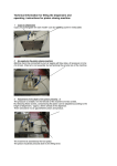
Instruction
Manual
Rotameter in Jacket Fitting
RAGH
Unpacking
: All packaging material must be removed. The transport securing
device of the float must be removed. If the float is packed
separately, take off the top bolted joint and the top stop and then
insert the float into the measuring tube.
Assembling position
: Vertical
Hints for Assembly
: Assemble tension-free! The connection tubes must be aligned.
With flanges make sure the screw holes are in line. Avoid
vibration. If necessary, support the tubes in front of and behind the
Rotameter with braces. Avoid large volumes of gas downstream
and upstram of the float (vibration due to compression).
Commissioning
: When functioning properly, the float (1) rotates freely in the flow.
With major floats made of plastic or metal, this can easily be seen
in their rotation. If the float does not rotate, either the device is
soiled or the vertical assembly requirement has been disregarded.
This only applies to floats with notches.The scale mark to which
the float adjusts its top edge is decisive for reading.
Maintenance
: To clean the rotameter, remove it from the tube. After the removal
of the two stops (6, 6a) and the float (1), the measuring tube (2)
can be cleaned without removing it from the fitting. For cleaning
we recommend using a bottle brush and soap and water solution.
Make sure the measuring tube does not get scratched. If the float
or the measuring tube show signs of wear and tear, we
recommend replacing them. To remove the tube, take off the
stops (6, 6a) and the float and then press the tube out of its O-ring
support (5) using a cylindrical plastic tube. The diameter of the
cylindrical plastic tube corresponds to the external diameter of the
measuring tube. Reassemble the parts in reverse order.
Safety hints
: The measuring tube is made of glass and therefore fragile. Avoid
any damage coming from the outside. The specified maximum
pressures must not be exceeded. Pressure peaks must not
exceed the specified maximum pressure either. Pressure shock
may hit the float against the top stop (6a) with high speed. This
may result in the destruction of the stop and the measuring tube
Tension in the glas over 6N/mm² have tobe avoided. Therefore
the temperature difference in the glas may not exceed 40°C.
Please avoid temperature shocks. ROTA YOKOGAWA gives no
warranty for the improper use of flow meters having glass floats.
Due to the uncontrollability of the material YOKOGAWA cannot
guarantee that the material is fracture-proof.
Further hints can be found in VDI/VDE 3513.
Caution
: The metering tube, the float and the scale must always be
kept together.
Units with limitswitches /GM1...GM2 : See instruction manual IM 1R1B19-E-H.
IM 1R1B5-E-H
2nd edition
Position
Quantity
Description
1
1
Float
2
1
Metering Tube
3
1
Exchangable scale
4
1
Jacket fitting
5
2
O-ring holder
6
1
Bottom stop
6a
1
Top Stop
7
2
Insertion parts
8
2
Sleeve nuts
9
2
Scale holder
10
4
O-rings
11
2
Gasket
T1.EPS
IM 1R1B5-E-H