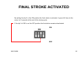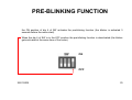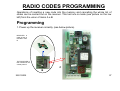
1
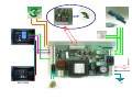
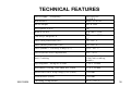
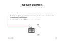
CONTROL PANEL INSTALLATION MANUAL
BASC/2002
•
•
•
•
The PCB Basc/2002 is a electronic control board used for overhead swing
garage motors with or without clutch. It is strong and reliable. Its reduced
dimensions allow the insertion of the unit inside the motor. The
introduction in IP55 containers is not provided.
It is arranged for the use of a timer to be connected to the START input for
programmed opening and closing. Free from interference and protected
against atmospheric and electrostatic discharges.
The control board Basc/2002 has succeeded all tests concerning the
electromagnetic emissions and the immunity to the interference as provided
by the European rules in force.
It conforms to the directives EMC 89/336/CEE, 92/31/CEE, BT 73/
23/CEE and 93/68/CEE
25/01/2005
14
SUGGESTIONS ON THE CONTROL
PANEL INSTALLATION
•
•
•
•
•
The installation must be done by specialized technicians, in compliance with the local, national and European
regulations in force (UNI 8612) as well as to the instructions quoted on this manual. The installer must verify the
type of system and if necessary connect security devices (differential and magnetothermic switches) which comply
with the current regulations. The manufacturer declines any responsibility for damages to people or things caused
by wrong installations, improper and unreasonale usages,tampering as well as by non observance of the current
regulations.
Protect the control board with a 6A automatic switch or with a 16A monophase switch and fuses. Make sure that
the ground wire (terminal 1) is properly connected to the ground dispenser of the system. It is necessary to respect
the phase and neutral polarity in the 230V a.c. power supply line (terminal 3= phase, terminal 2= neutral). The
minimum section required for the power circuits (motors and blinker outputs) is 1,5 mmq. Always use separated
connection for auxiliary and control (inputs) power ciurcuits in order to avoid interferences or damages caused by
unduced tensions (do not use only one multipolar wire). In case of lines longer than 50 mt it is advisable to
dismatch the control circuits with some relays in the control board. If the n.c. inputs (limitswitches, photocells, stop
button) are not used they have to be connected to the common (terminal 15) through jumpers.
After installing all the security and electrical devices (buttons, photocells, blinkers, etc.) and having done all the
electrical connections, power up the control unit and check the following:
Remember that the inputs which are not used have to be jumpered. If led DL1 (red) is not on, check that the 230V
a.c. power tension arrives to the terminal 2 and 3, also control the fuses integrity and if necessary replace them
with others of the same capacity.
After starting the motors make sure that they can be stopped with a force no higher than 150N (
about 15 Kg) according to the UNI 8612 regulations. If necessary, adjust the force through the POWER
trimmer.
25/01/2005
15
25/01/2005
1
7
8
2
9
3
fase
neutro
16
220 VOLT
4
5
6
10 11 12 13 14 15 16 17 18 19
..
..
Electrical chart BASC 2002,
wiring and position ON OFF
of the SW.
SW
ON
OFF
25/01/2005
17
TECHNICAL FEATURES
D im en sion s
220 /230V A.C.
50 /60 H Z
m m 87 x 170 x 50
Mo tor ou tput
700 W m ax
Ab sorpt ion at re st
3W
Blink er Po w er
Fu se (un it p rot ec tion ) (F1 )
40 W m ax – 230V
A.C.
40 W m ax – 230V
A.C.
2 A – 250 V
Fu se (m otor p rot ec tion ) (F2 )
5 A – 250 V
Fu se (Blinke r / Cou rtesy L am p) (F3 )
0,5 A – 250 V
Po w er (m otor force ad jus tm en t)
50 % - 98 %
Po w er s upply / Fre qu ency
Cou rtesy L am p Pow er
Op ening and C los ing wo rk tim e
A rra ng ed to the us e
of the anti-cr ush ing
m odul e.
3 – 60 s ec onds
Au tom atic C los ing Time BRE A K TI M E
3 – 75 s ec onds
M ax S tar t Pow er in op ening cy cl e (fi xed )
2 s ec onds
Final Strok e (fi xed )
2 s ec onds
W orking Te mp er ature
20 ° C + 50 ° C
An ti- C rush ing
25/01/2005
18
DIP SETTING
• WARNING: all the adjustments must be carried out
with the door in close position. After the dip-switch
programming it is necessary to turn off the control
board first and then turn it on again in order to
activate the new adjustments.
25/01/2005
19
START POWER
By setting the dip 1 of SW in ON (see picture below), the start power is activated as the
two motors start, it lasts 2 seconds
By setting the dip 1 of SW in OFF the start power is deactivated.
ON
OFF
25/01/2005
20
WORKING CYCLE CHOICE
By setting the dip 2 of SW in ON the automatic function is activated. The door, soon after an
opening impulse, will carry out the complete cycle open/stop/close.
By setting the dip 2 of SW in the OFF position the step by step function will be activated. That
is by giving one, two, three, four,… impulses the door will carry out first the opening cycle;
when the second impulse is given the door will stop, when the third one is given the door will
start closing and when the fourth si given the door will open again…
ON
OFF
25/01/2005
21
FINAL STROKE ACTIVATED
By setting the dip 3 in the ON position the final stroke is activated, it gives full force to the
motor for 2 seconds at the end of the closing cycle.
If the dip 3 of SW is on the OFF position the final stroke remains deactivated
ON
OFF
25/01/2005
22
PRE-BLINKING FUNCTION
the ON position of dip 4 of SW activates the pre-blinking fucntion (the blinker is activated 3
seconds before the motor start).
When the dip 4 of SW is in the OFF position the pre-blinking function is deactivated (the blinker
gets activated at the same time of the motor).
ON
OFF
25/01/2005
23
OPENING/CLOSING TIME
ADJUSTMENT
The working time can be adjusted through
the trimmer WORK between 3 and 60
seconds. The working time has to be set
up so that the motor remains powered up
for a two three seconds seconds after the
end of the opening or closing cycle of the
door.
25/01/2005
24
AUTOMATIC CLOSING TIME
ADJUSTMENT (BREAK TIME)
Make sure that the dip 2 of SW is on the ON position.
Adjust the trimmer BREAK to modify the automatic
closing time (break time). It is possible to change it from a
minimum of 3 to a maximum of 75 seconds.
Set the dip 2 of SW on the OFF position to exclude the automatic
closing.
POWER ADJUSTMENT
Use the trimmer POWER. Adjust the force according to the
UNI 8616 regulations.
25/01/2005
25
ANTI-CRUSHING MODULE
(OPTIONAL)
• An anti-crushing module is available optionally to be
installed on the control unit. This device works both in
opening and closing and in case of any crush of the door
against an obstacle, it reserves the movement for two
seconds and then stops. The unit indicates the module
operation is indicated with a quick flashing of led D9
(green).
• The door will start the opening only when the obstacle is
removed and the start command is pressed. For the
function of the anti-crushing module it is necessary to
install the closing and opening limit switches.
25/01/2005
26
RADIO CODES PROGRAMMING
Operations of inserting a new code into the memory and cancelling the whole list of
codes can be carried out on the receiver. This last one is made (see picture on the low
left) from the union of items A e B.
Programming
1. Power up the receiver correctly (see below picture).
RECEIVER: is
made of item A
inserted in item
B
A
THE RECEIVER is
then inserted in the
control panel C.
C
B
25/01/2005
27
RADIO CODES PROGRAMMING
Red light LED
2. To program a code on the first channel, press
shortly the button “LEARN”: the red LED lights on
indicating that programming is in progress. Carry
out a transmission by pressing any button of the
remote control. The code is inserted into the
memory. At the end the LED returns to the nonlighting state.
3. To program a code on the second channel, keep
pushed the “LEARN” button: the red light LED
switches off and switches on. Release the button,
and the LED light switches on again. Do a
transmission activating the transmitter (Microkey/R,
114401 Keypad, Remote control) that you want to
memorize. The code has been learned. At the end
the LED goes back to non-lighting phase.
25/01/2005
Button “MEM. CLEAR”
Button “LEARN”
28
RADIO CODES PROGRAMMING
4. Memorise all the transmitters repeating operations 2. or 3.
5. After the “LEARN” button pressure, exit from the
programming comes about automatically if no transmitter
button is pressed within 15 seconds.
6. The codes remain in the memory even if the receiver’s
power supply is cut.
Red light LED
Button “MEM. CLEAR”
Button “LEARN”
IF MORE THAN ONE ACTIVATOR IS MEMORIZED
(Microkey/R, 114401 keypad, Remote control etc.) THE
PROGRAMMING MUST ALWAYS START WITH THE
REMOTE CONTROL, OTHERWISE THERE COULD BE
SOME EXCLUSIONS.
Total cancellation codes
1. Press and keep pressed the “MEM. CLEAR” button till
the LED red light starts flashing.
2. The confirmation is given as soon as the LED stops
flashing.
25/01/2005
29
RADIO CODES PROGRAMMING
TECHNICAL FEATURES
Power supply
Average Work/Rest
consumption
Reception frequency
RF bandwidth at Š3dB
Sensitivity
Code
Number of codes that can be
memorized
Number of outputs
Contact rating relay
Signals
Working temperature
Storage temperature
Size / Weight
25/01/2005
12 - 24 Vac/dc
25 mA/45 mA
433.920 MHz
± 250 kHz (p.n 2-5000748)
-100 dBm (p.n 2-5000748)
Digital at 54 bit
312
1/2
1 A @ 120 Vac/30 Vdc
Red led
-10/+55 C
-40/+85 C
50 x 51 x 17 mm 40g
30