1
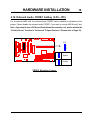
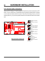
TS-AKXA
USER’S MANUAL
AMD K7 Athlon CPU
TS-AKXA Motherboard
Supporting AMD K7 Athlon CPU
200 MHz Front Side Bus Frequency
AGP 4X
®
VIA KX133/686A Chipset
Welcome !!
Congratulations on your purchase of this great value motherboard, with its range of special
features and innovative onboard functions, built around the advanced architecture of the new
VIA® KX133/686A Chipset. More details to follow later in this manual.
Our Website
Please come and visit us at our website on http://www.transcendusa.com/. You’ll find plenty of
interesting information about this and many other quality Transcend products.
Your User’s Manual
This User’s Manual is designed to help end users and system manufacturers to set up and
install the motherboard. All of the information within has been carefully checked for accuracy.
However, Transcend Information, Inc. (hereafter referred to as “Transcend”) carries no
responsibility or liability for any errors or inaccuracies which this manual may contain. This
includes references to products and software. In addition, the information and specifications
are subject to change without prior notice.
Disclaimer
Transcend provides this manual “as is” without any warranty of any kind, either expressed or
implied, including - but not limited to - the implied warranties, conditions of merchantability or
fitness for a particular purpose. Transcend, its management, employees, distributors and
agents are in no way liable for any indirect special, incidental or consequential damages,
including loss of profits, loss of business and the like. This is even if Transcend has been
advised of the possibility of such damages arising from any defect or error in this manual or
product.
Trademarks
All brands, product names and trademarks mentioned in this document are the property of
their respective owners or companies and are used solely for identification or explanation. It
is Transcend policy to respect all product rights.
Copyright
This manual may not, in whole or in part, be photocopied, reproduced, transcribed, translated
or transmitted, in whatever form or language, without the written consent of the manufacturer,
except for copies retained by the purchaser for personal archiving purposes.
Manual Version: 1.0
Release Date: April, 2000
Copyright © April 2000 Transcend Information, Inc.
Table of Contents
CHAPTER 1 INTRODUCTION
1
1.1 Essential Handling Precautions ......................................................................................1
1.2 Checklist: Hardware Required for Setup .......................................................................2
1.3
Package Contents .................................................................................................. 2
1.4 Specifications and Features ...........................................................................................3
CHAPTER 2 HARDWARE INSTALLATION
5
2.1 Transcend’s TS-AKXA Motherboard ............................................................... 5
2.2 Layout of Transcend’s TS-AKXA Motherboard ................................................. 6
2.3 CPU Installation ............................................................................................ 7
2.4 Memory Configuration ................................................................................... 9
2.5 Primary/Secondary IDE Connectors ............................................................. 10
2.6 Floppy Disk Drive Connector .......................................................................... 11
2.7 Fan Power Connectors ............................................................................... 11
2.8 Wake-on-LAN Connector ............................................................................ 12
2.9 IrDA-Compliant Infrared Module Connector .................................................. 12
2.10 Panel Connectors ....................................................................................... 13
2.11 V/O Voltage Control ....................................................................................... 15
2.12 Suspend to RAM (S3) Function Support.................................................................. 16
2.13 Power Connector...................................................................................... 17
2.14 External Back Panel I/O Ports ..................................................................... 17
2.15 Using JP7 to clear CMOS Jumper........................................................................... 18
2.16 Onboard Audio CODEC Setting .............................................................................. 19
2.17 Internal Audio Connectors ...................................................................................... 20
2.18 Internal USB Port Connector ................................................................................ 21
CHAPTER 3 BIOS SETUP
22
3.1
BIOS Setup.................................................................................................. 22
3.2
The Main Menu ........................................................................................... 22
3.3
Standard CMOS Features............................................................................. 24
3.4
Advanced BIOS Features............................................................................. 27
3.5
Advanced Chipset Features .......................................................................... 31
3.6
Integrated Peripherals ........................................................................... 35
3.7
Power Management Setup......................................................................... 39
3.8
PnP/PCI Configurations ................................................................................ 44
3.9
Frequency/Voltage Control ........................................................................... 46
3.10
Load Fail-Safe Defaults ............................................................................. 47
3.11
Load Optimized Defaults.............................................................................. 47
3.12
Supervisor Password ................................................................................ 48
3.13
User Password.................................................................................... 49
3.14
Save & Exit Setup................................................................................... 50
3.15
Exit Without Saving................................................................................... 50
CHAPTER 4 BIOS UPGRADE
51
4.1
How to Check Your BIOS File Name and Version .......................................... 51
4.2
How to Download the Correct BIOS File from Our Web Site.............................51
4.3
How to Upgrade Your Motherboard BIOS .................................................... 52
INTRODUCTION
1
CHAPTER 1 INTRODUCTION
1.1 Essential Handling Precautions
IMPORTANT. Read this page before unpacking your motherboard!
• Power Supply
Be careful! Always ensure that the computer is disconnected from the power supply when
working on the motherboard and its components.
• Static
Static electricity may cause damage to the delicate integrated circuit chips on your motherboard.
Before handling the motherboard outside of its protective packaging, ensure that there is no
static electric charge in your body. To avoid this risk, please observe these simple precautions
while handling the motherboard and other computer components:
1. If possible, wear an anti-static wrist strap. This fits around your wrist and is connected to
a natural earth ground.
2. Touch a grounded or anti-static surface, or a metal fixture such as a pipe or the chassis of
your system, before touching the motherboard.
3. When you have removed the motherboard from its anti-static packaging, try to hold it only
by the edges, without touching any components.
4. Avoid contacting the components on add-on cards, motherboards, and modules with the
golden fingers (gold-colored connectors) which plug into the expansion slots.
5. It is safest to handle system components only by their mounting brackets.
6. Keep components which are not connected to the system in the anti-static packaging
whenever possible.
These precautions help to reduce the risk of static build-up and ensure any static discharge is
harmless to your equipment.
• Battery Replacement
The battery which holds the system settings memory on your motherboard should not require
replacement for at least five years, and probably much longer. In picture 2.2, it is located near
the bottom right hand corner.
INTRODUCTION
2
Please replace your battery only with the same type, or a similar type recommended by the
manufacturer. If the battery is replaced incorrectly, there is a risk of a short circuit or explosion.
Used batteries should disposed of according to the manufacturer’s instructions.
• Electric Screwdrivers
To reduce the risk of damage to the motherboard due to excessive torque, avoid setting
electric screwdrivers above 7.5 kg/cm.
1.2 Checklist: Hardware Required for Setup
It is advisable to have all of these items of hardware available before you unpack your
motherboard from its anti-static packaging and start building your system.
- Computer case and chassis with appropriate power supply. (300W recommandod)
- Monitor.
- Slot A Central Processing Unit (CPU).
- DIMM memory module.
- PS/2 or USB Keyboard.
- PS/2 or USB Mouse.
- Hard Disk Drive.
- Floppy Disk Drive.
- CD-ROM Drive.
- (Optional) External Peripherals: printer, speakers, plotter, modem.
- (Optional) Internal Peripherals: modem, LAN cards.
1.3 Package Contents
This motherboard package should contain the following items. Please check them as soon as
you unpack. If you find any damaged or missing items, please contact your retailer.
- TS-AKXA motherboard
- 1 x CD-ROM
- 1 x FDD cable
- 1 x Ultra DMA/66 cable
- User’s Manual
- 1 x External USB connector
INTRODUCTION
1.4 Specifications and Features
• CPU
- Supports AMD K7 Athlon CPU
• Chipset
- VIA KX133/686A AGPset (AGP4X, Ultra DMA 33/66)
• DRAM Memory
- Supports Synchronous DRAM
- 3 x 168-pin DIMM module sockets on board
- Up to 1.5GB memory size
- 8/16/32/64/128/256/512MB SDRAM DIMM
- Supports ECC
- 64/72 data bits structure only
- PC100/PC133 SDRAM compliant
• I/O BUS Slot
- 1 x AGP slot
- 5 x Master/Slave PCI slots (PCI 2.2 compliant)
- 1 x ISA slot
- 1 x AMR slot (Shared with ISA slot)
• I/O Functions
- Supports PIO Mode 3,4 ATAPI devices and Ultra DMA33/66
- Supports 2 high speed UART 16550 COM ports
- Supports SPP/EPP/ECP LPT port
- Supports 1.44/2.88 MB floppy drive
- Supports PS/2 Mouse and PS/2 Keyboard
- Supports IrDA port
- Supports 4 Universal Serial Bus (USB) ports
3
INTRODUCTION
4
• Award BIOS
- Supports Plug-and-Play, PC99
- Supports ACPI, APM, DMI and Green Feature
- Easy BIOS Recovery
• Wake Up Features
- Supports Wake-on-LAN function
- Remote Ring Wake Up
- Time Wake Up
• PCB Dimensions
- ATX form factor, 4-layer PCB, 21.3cm x 30.5cm (8.4 inch x 12 inch)
• Switching Voltage Regulator
- Intel VRM 8.4 compliant
• Other Features
- Year 2000 compliant
- Anti-Virus Boot up
- For LM782 Hard ware Monitor
- System voltage monitors for CPU Vcore, +2.5, +3.3V, +5V and +12V
HARDWARE INSTALLATION
CHAPTER 2 HARDWARE INSTALLATION
2.1 Transcend’s TS-AKXA Motherboard
CPU
I/O Port
· General MIDI Port & Audio Jack
(Line-In, Line-Out, MIC-In)
· 2 x COM Ports & 1 x Parallel Port
· 2 x USB Ports
· PS/2 KB Port & PS/2 Mouse Port
Memory
· AMD Athlon K7 Slot A CPU
(FSB 200MHz)
· 3 x 168 -pin DIMM Sockets
· 8MB~1.5GB SDRAM
Switching Reg.
FDD Connector
VIA
KX133 Chipset
· Supports 200MHz FSB
PCI IDE Connector
· Bus Master
· PIO Mode 3/4
· DMA Mode 2
· Ultra DMA 33/66
AGP Connector
· Supports AGP1X/2X/4X
IrDA
VIA 686A Super
South Bridge
· Build-In Super I/O
WOL Header
· Wake-on-LAN
Flash EEPROM
· Award BIOS
· PnP,DMI
· ACPI compliant
Expansion Slots
External USB
Connector
· 2 x USB Ports
AC97 CODEC
· AC97 V2.1 Audio CODEC
LM 782Slots
Expansion
· Hard ware Monitor
· 5 x PCI Slots
· 1 x AMR Slot
·1 x ISA Slot
(Shared with AMR)
5
HARDWARE INSTALLATION
6
KB MOUSE
PS/2
JP1
T:Mouse
B:Keyboard
JP2
2.2 Layout of Transcend’s TS-AKXA Motherboard
CPU_FAN1
Parallel Port
Slot A
COMB
VIA
8371
Chipset
VIA
686A
Chipset
SYS_FAN1
Transcend
WOM1
JP5
PCI Slot3
PCI Slot4
WOL
PCI Slot5
FLASH ROM
AMR Slot
ISA Slot
Panel
USB2
IDE2
IR1
JP7
AUX_IN
CD_IN2
VIDEO_IN
PCI Slot1
PCI Slot2
AC97
CD_IN1
IDE1
AGP
MODEM
Li Battery
MIC-in
Line_in
Game Port
Line_out
COMA
FDC
PWR1
USB 1
DIMM1 (168 Pin SDRAM Module)
DIMM2 (168 Pin SDRAM Module)
DIMM3 (168 Pin SDRAM Module)
USB
LM782
HARDWARE INSTALLATION
7
2.3 CPU (Central Processing Unit) Installation
So far you have familiarized yourself with the handling precautions, checked you have all of
the necessary hardware for building your system, inspected the motherboard package contents
and looked at the layout of the motherboard. This chapter will take you step by step through
the process of installing the different hardware devices onto it.
Caution
1. Remember to always make sure the system power is off before installing or removing
any devices.
2. Don’t forget the static electricity precautions.
3. Be careful ! Inserting hardware onto your motherboard incorrectly can damage it.
The motherboard has a ZIF Slot A which houses the CPU. A fan is necessary for the CPU to
prevent overheating. If there is no fan on it, please purchase one before you turn on your
system.
WARNING! Be sure that sufficient air circulation is available across the processor’s
passive heatsink. Without sufficient circulation, the processor could overheat and
damage both the processor and the motherboard. You may install an auxiliary fan, if
necessary.
Please follow the steps below to install the CPU:
Step 1:
To install the CPU, first turn off your system and remove its cover. Locate the ZIF socket and
open it by first pulling the lever sideways away from the socket then upwards to a 90-degree
right angle. Insert the CPU in the correct direction, you should have a CPU fan to cover the face
of the CPU. With the added weight of the CPU fan, no force is required to insert the CPU. Once
completely inserted, close the socket’s lever while holding down the CPU.
HARDWARE INSTALLATION
8
Step 2:
Connect the CPU’s fan cable to the CPU-FAN connector indicated on the diagram below.
Ensure that the cable is connected correctly! It will be obvious which way it fits.
CPU_FAN
Transcend
CPU Installation
HARDWARE INSTALLATION
9
2.4 Memory Configuration
This motherboard must be installed with DIMMs (Dual Inline Memory Modules). The DIMMs
must be 3.3 Volt synchronous DRAM modules. The VIA KX 133 chipset supports PC100,
PC133 and Virtual Channel Memory (VCM). It also supports ECC (Error Checking and Correcting)
modules. You can install memory in any combination as follows:
DIMM Location
168-pin DIMM
DIMM1
SDRAM 8,16, 32, 64,128, 256, 512MBytes
DIMM2
SDRAM 8,16, 32, 64,128, 256, 512MBytes
DIMM3
SDRAM 8,16, 32, 64,128, 256, 512MBytes
Total Memory
1.5GBytes (max.)
NOTE: Different types of DRAM modules (eg. PC100 and PC133 DIMMs) should not be
installed on one motherboard at the same time.
Transcend
3.3V Position
Unbuffered Position
168 Pin SDRAM Module (DIMM1)
168 Pin SDRAM Module (DIMM2)
168 Pin SDRAM Module (DIMM3)
168 Pin DIMM Sockets
10
HARDWARE INSTALLATION
2.5 Primary / Secondary IDE Connectors (Two 40-pin IDE)
This mainboard supports two 40-pin IDE connectors marked as IDE1 (primary IDE channel)
and IDE2 (secondary IDE channel). Each channel supports two IDE devices, making a total of
four devices. Connect your Hard Disk (the main one if you are using more than one) to the
“Master” connector (at the end of the cable) and connect it to the IDE1 (see important note
below). If your HDD supports UltraDMA/66, you must use an 80-wire cable, otherwise the
HDD won’t be able to reach this speed.
If you intend to operate two IDE devices from the same channel, one device must be set to
“Master” mode, the other to “Slave” mode. A Hard Disk, CD ROM or other IDE device can
have either setting, depending on device’s jumper. Please refer to the device’s manual for
more information.
NOTE: The connectors must be attached to the IDE channels the right way round.
Make sure that the red stripe on one edge of the ribbon cable (this may be faint and
could also be a dotted line) is the nearest to PIN1 (on the left as the motherboard is
shown in the picture below).
Transcend
Note: Orient the red
stripe to Pin1
Primary IDE Connector
PIN1
IDE1
PIN1
IDE2
Secondary IDE Connector
IDE Connectors
HARDWARE INSTALLATION
11
2.6 Floppy Disk Drive Connector (34-pin FDC)
This connector supports the provided floppy disk drive ribbon cable. After connecting the
single end to the board, connect the two plugs on the other end to the floppy drives.
Note: Orient the red
stripe to Pin1
Transcend
Floppy Drive Connector
FDC
PIN1
Floppy Disk Drive Connector
2.7 Fan Power Connectors
There are two fan power connectors on the mainboard: the CPU-FAN and the CASE-FAN. Each
connector provides +12V power. Make sure they are in the right orientation, or they may cause
damage. These connectors support cooling fans of 500 mA (6W) or less.
Transcend
CPU-FAN
FAN
Fan Power Connectors
GND
+12V
Rotation
SYS-FAN
12
HARDWARE INSTALLATION
2.8 Wake-on-LAN Connector (3-pin WOL)
This connector connects to LAN cards with a Wake-on-LAN output. The system can Power up
when a wakeup packet or signal is received from the LAN card.
NOTE: This function requires that the “LAN Wake Up” function in the POWER MANAGEMENT
SETUP is set to “Enabled” and that your system has an ATX power supply with at least
720mA +5V standby power.
Transcend
WOL
+5 Volt Standby
GND
PME
Wake-On-LAN Connector
2.9 IrDA-Compliant Infrared Module Connector (5-pin IrDA)
The IrDA connector can be configured to support a wireless infrared module. With this module
and application software such as Laplink or Win95 Direct Cable Connection, the user can
transfer files to or from laptops(notebooks), PDAs and printers.
Transcend
IrDA
1
+5V
NC
IRRX
GND
IRTX
5
IrDA Connector
HARDWARE INSTALLATION
13
2.10 Panel Connectors
Transcend
PWR_LED
1
SPEAKER
+
2
19
+
+
HD_LED
20
SLP
RST
PW_BN
Panel Connectors
Power LED Lead (3-pin POWER LED)
This 3-pin connector attaches to the power LED.
Pin1 : +5V
Pin3 : NC
Pin5 :
GND
Speaker Lead (4-pin SPEAKER)
This 4-pin connector connects to the case-mounted speaker.
Pin13 :
+5V
Pin15 : GND
Pin17 :
NC
Pin19 : SPK
Harddisk LED Lead (2-pin HD_LED)
This 2-pin connector connects to the LED of the hard disk. The LED lights up when the HDD is
active.
Pin6 : +5V
Pin8 :
GND
14
HARDWARE INSTALLATION
Sleep Button Lead (2-pin SLEEP)
Pin10 : SLEEP
Pin12 : GND
Reset Switch Lead (2-pin RESET)
This 2-pin connector connects to the case-mounted reset switch for rebooting your computer
without turning off your power switch.
Pin14 : RESET
Pin16 : GND
Software Power-Off Lead (2-pin SOFT_OFF)
Attach the SOFT_OFF Switch of the panel to this connector.
Pin18 : SOFT-OFF
Pin20 : GND
HARDWARE INSTALLATION
15
2.11 Vio Voltage Control (JP2)
The jumper is used to switch Vio Voltage. It can set the default setting (1-2) to standard 3.3V,
or change to higher voltage (3.4V) for overclocking or compatibility .
JP2
1
Transcend
1
1
Vio Voltage Control
Normal Voltage
(Default)
Higher Voltage
16
HARDWARE INSTALLATION
2.12 Suspend to RAM (S3) Function Support (JP5)
The jumper is used to set the Suspend to RAM function. If you don’t need the function, it can be
changed to (2-3) to disable the function.
JP5
1
Transcend
1
1
Suspend to RAM (S3) Function
Enable
Disable
HARDWARE INSTALLATION
17
2.13 Power Connector (20-pin PWR-CONN)
Make sure to plug the ATX power supply connector in the right direction. The pin definition is
shown below. Make sure that your ATX power supply can support at least 720mA on the
standby lead.
GND
Power Good
+5.0V Standby
+12.0V
+5.0V
+5.0V
GND
-5.0V
GND
GND
GND
PSON#
+3.3V
-12.0V
+3.3V
+3.3V
Transcend
GND
+5.0V
GND
+5.0V
PWR-CONN
PSON# : Power Supply on
Power Connector
2.14 External Back Panel I/O Ports
There are 5 kinds of external connectors on the motherboard. The view angle of the drawing
shown on next page is from the back panel of the housing.
1. PS/2 Mouse Port (Green, 6-pin MOUSE)
The onboard PS/2 Mouse port is a 6-pin Mini-Din connector marked “MOUSE”
2. PS/2 Keyboard Port (Purple, 6-pin KB)
The onboard PS/2 Keyboard port is a 6-pin Mini-Din connector marked “KB”.
3. Universal Serial Bus (USB) Ports 1 & 2 (Black, two 4-pin USBs)
You can attach USB devices to the USB port. The motherboard contains two USB ports,
which are marked as “USB”. (USB Ports 3 & 4 are on-board connectors with 2x5
Header.
4. Parallel Port (Burgundy, 25-pin PRN)
The onboard printer port is a 25-pin D-type connector marked “PRN”.
5. Serial Ports (Turquoise, two 9-pin COMA/COMB)
The onboard serial ports are 9-pin D-type connectors on the back panel of
motherboard. The serial port 1 is marked as “COMA”, and the serial port 2 is marked
as “COMB”.
18
HARDWARE INSTALLATION
4. Parallel Port
(Printer)
1. PS/2 Mouse
7. Game/MIDI Port
3. USB1
3. USB2
5. COMB
COMA
2. PS/2 Keyboard
9. Line-in
8. Line-out
10. MIC-in
External Back Panel I/O Ports
2.15 Using Jumper JP7 to Clear CMOS
To clear the CMOS data, you should turn off your computer’s power and short pin1 and pin2
of JP7.
Transcend
JP7
1
1
Normal
1
CLEAR_CMOS
Clear CMOS Jumper
HARDWARE INSTALLATION
19
2.16 Onboard Audio CODEC Setting (3-Pin JP8)
For an external AMR card, the onboard audio CODEC can be enabled or disabled via this
jumper. Please disable the onboard audio CODEC, if you want to use an AMR Sound Card.
Note : If you want to use a PCI Sound Card with audio controller on it, please disable the
“OnChip Sound” function in “Advanced” Chipset Features” (Please refer to Page 32).
Transcend
JP8
1
2
3
CODEC Selection Jumper
1
2
3
Enable
1
2
3
Disable
HARDWARE INSTALLATION
20
2.17 Internal Audio Connectors
These connectors allow you to receive stereo audio input from sound sources such as a CDROM, TV tuner, or MPEG card. The MODEM connector allows the onboard audio to interface
a voice modem card with a matched connector. It also allows the sharing of mono_in (such as
a phone) and mono_out (such as a speaker) between the onboard audio and the voice modem
card.
Left Audio Channel
GND
Right Audio Channel
CD1(Black)
Transcend
CD2
GND
Right Audio Channel
Left Audio Channel
Left Audio Channel
GND
Right Audio Channel
VIDEO (White)
Left Audio Channel
GND
Right Audio Channel
AUX(Green)
Internal Audio Connecotrs
Modem-In
(Voice to Modem)
Modem-Out
(Voice from Modem)
GND
MODEM
HARDWARE INSTALLATION
21
2.18 Internal USB Port Connector (10-Pin USB3/4)
You can use the provided serial port bracket to add a serial port for additional serial devices.
Regarding the onboard COMA, please refer to Section 2.14 “External Back Panel I/O Ports”
(page 17).
NOTE : Please make sure that the two red stripes on the cable are seated on Pin1 and
Pin2.
Transcend
USB4
USB3
1
2
VCC
VCC
USB3-
USB4-
USB3+
USB4+
GND
GND
GND
GND
9
10
Internal USB Port Connecotr
Congratulations, you have now completed Hardware Setup! This means that you can move
on to Chapter 3, the BIOS Setup section and turn on your PC.
BIOS SETUP
22
CHAPTER 3 BIOS SETUP
3.1 BIOS Setup
Award BIOS has a built-in Setup program that allows users to modify the basic system
configuration. This information is stored in CMOS RAM, so it can retain the Setup information
when the power is turned off. When the CMOS battery fails, it will cause the data to be lost. If
that happens, please set up your configuration parameters again after replacing the battery.
Please refer to Section 1.1, Essential Handling Precautions (Page 1).
3.2 The Main Menu
As you turn on or reboot the system, the BIOS is immediately activated. It will read the system
configuration information, and check the system through Power On Self Test (POST). During
the POST process, press the [Del] key, and you can enter the Award BIOS configuration
system. The following screen will appear.
In the Award BIOS system, you can use the arrows (
) to highlight an item,and
press the [Enter] key to enter the sub-menu. The following keys help you navigate in Setup.
[Esc]
Main Menu: Quit and do not save changes into CMOS RAM
Other pages: Exit current page and return to Main Menu
[PgUp] Increase the numeric value or make changes
[PgDn] Decrease the numeric value or make changes
BIOS SETUP
[+]
Increase the numeric value or make changes
[-]
Decrease the numeric value or make changes
23
[F1] General help on setup navigation keys
[F5] Load previous values from CMOS
[F6] Load the Fail-Safe Defaults from BIOS default table
[F7] Load the Optimized Defaults
[F10] Save all CMOS changes, and exit
The following is a brief summary of each setup category
• Standard CMOS Features
Options in the original PC AT-compatible BIOS
• Advanced BIOS Features
Award enhanced BIOS options
• Advanced Chipset Features
Available options specific to your system Chipset
• Integrated Peripherals
I/O subsystems that depend on the integrated peripheral controllers in your system
• Power Management Setup
Advanced Power Management (APM) and Advanced Configuration and Power Interface
(ACPI) options
• PnP/PCI Configurations
Plug and Play standard and PCI Local Bus configuration options
• PC Health Status
To display the fan status, CPU temperature, system temperature etc., and to provide the
temperature monitoring option
• Frequency / Voltage Control
To control the frequency and voltage of the CPU
• Load Fail-Safe Defaults
To load the most basic BIOS default values required for your system to operate
• Load Optimized Defaults
To load the BIOS default values that are factory settings for optimal system performance
24
BIOS SETUP
• Set Supervisor / User Password
To change, set, or disable a password
• Save & Exit Setup
To save settings in nonvolatile CMOS RAM and exit Setup
• Exit Without Saving
To abandon all changes and exit Setup
3.3 Standard CMOS Features
• Date (mm:dd:yy) / Time (hh:mm:ss)
Highlight the items and use [PageUp] / [PageDown] to change the value of Date/Time.
• IDE Primary / Secondary Master / Slave
Press [Enter] to enter the sub menu.
BIOS SETUP
25
• IDE HDD Auto-Detection : Detect the HDD on this channel. If the detection is successful,
it fills the remaining fields on this menu.
• IDE Primary/Secondary Master/Slave : We recommend that you select “AUTO” for all
drives. The BIOS can automatically detect the specifications during POST (Power On
Self Test) while the system boots. You can also choose “Manual” to set the specifications
by yourself. The “None” setting means there is no device installed on this IDE channel.
• Access Mode : “Normal”, “LBA”, “Large”, or “Auto”.
- Normal : Maximum number of cylinders, heads, and sectors supported are 1024,16,
and 63 respectively.
- LBA (Logical Block Addressing) : During drive access, the IDE controller transfers
the data address described by sector, head, and cylinder number into a physical
block address. This will significantly improve data transfer rates for drives with
more than 1024 cylinders.
- Large : For drives that do not support LBA and have more than 1024 cylinders.
- Auto : The BIOS automatically determines the optimal access mode.
• Capacity : Disk drive capacity. Note that this size is slighty greater than the size of
formatted disk given by the disk-checking program.
• Cylinder : Number of cylinders
• Head : Number of heads
• Precomp : Write precompensation cylinder
• Landing Zone : Landing zone
• Sector : Number of sectors
BIOS SETUP
26
• Drive A / Drive B
Select the correct types of diskette drive(s) installed in the computer.
- None : No diskette drive installed
- 360K, 5.25 in. : 5-1/4 inch standard drive; 360 kilobyte capacity
- 1.2M, 5.25 in. : 5-1/4 inch high-density drive; 1.2 megabyte capacity
- 720K, 3.5 in. : 3-1/2 inch double-sided drive; 720 kilobyte capacity
- 1.44M, 3.5 in. : 3-1/2 inch double-sided drive; 1.44 megabyte capacity
- 2.88M, 3.5 in. : 3-1/2 inch double-sided drive; 2.88 megabyte capacity
• Floppy Mode 3 Support
Supports some particular Japanese floppy drives ( 3.5 inch drives with 1.2 MB capacity ).
• Video
Select the type of primary video subsystem in your computer. The BIOS will detect the
correct video type automatically. The BIOS supports a secondary video subsystem, but do
not select it in this Setup.
- EGA/VGA : Enhanced Graphics Adapter/Video Graphics Array. For EGA, VGA, SEGA,
SVGA or PGA monitor adapters.
- CGA 40 : Color Graphics Adapter, powers up in 40-column mode.
- CGA 80 : Color Graphics Adapter, powers up in 80-column mode.
- MONO : Monochrome adapter, including high resolution.
• Halt On
During the Power On Self Test (POST), the computer stops if the BIOS detects a hardware
error. You can set the BIOS to ignore certain errors during POST and continue the boot-up
process. The followings are the selections.
- All Errors : If the BIOS detects any non-fatal errors, POST stops and prompts you
to take corrective action.
- No Errors : POST does not stop for any error.
- All, But Keyboard : If the BIOS detects any non-fatal errors except keyboard, POST
stops and prompts you to take corrective action.
BIOS SETUP
27
3.4 Advanced BIOS Features
The “Advanced BIOS Features” option allows you to improve your system performance and
sets up system features according to your preference.
• Virus Warning
When this function is enabled, you will receive a warning message if a program (specifically,
a virus) attempts to write to the boot sector or the partition table of the hard disk drive. You
should then execute an anti-virus program. Keep in mind that this feature protects the boot
sector only, not the entire hard drive.
NOTE: Many disk diagnostic programs that access the boot sector table can trigger
the virus warning message. If you plan to run such a program, we recommend that
you first disable the virus warning.
28
BIOS SETUP
• CPU Internal Cache / External Cache
Cache memory is additional memory that is much faster than conventional DRAM (system
memory). CPUs from 486-type and up contain internal cache memory. Most, but not all,
modern PCs have additional (external) cache memory. When the CPU requests data, the
system transfers the requested data from the main DRAM into cache memory for even
faster accessed by the CPU. The “External Cache” field may not appear if your system does
not have external cache memory.
• CPU L2 Cache ECC Checking
Select “Enabled” to make sure the data is accurate.
• Processor Number Feature
This function was designed with the internet in mind. Select “ Enable” to make the processor
serial number serve as a means of identifying your system.
• Quick Power On Self Test
Select “Enabled” to reduce the amount of time required to run the Power On Self Test
(POST). The Quick POST skips certain steps. We recommend that you normally disable
Quick POST. It’s better to find a problem during POST than to lose data during your work.
• First / Second / Third Boot Device; Boot Other Device
The original IBM PCs loaded the DOS operating system from drive A (floppy disk). Therefore,
IBM PC-compatible systems are designed to search for an operating system first on drive
A, and then on drive C (hard disk). However, the BIOS attempts to load the operating
system from the devices in the sequence selected in these fields. In addition to the traditional
drives A (“Floppy”) and C (“HDD-0”), options include “HDD-1”, “HDD-2”, “HDD-3”, and “CDROM”; plus a “SCSI” hard drive, a “LS/ZIP” drive and a “LAN” drive. If your boot device is
not included in the list, you can set the “Boot Other Device” field to “Enabled”, and let the
system detect the drive automatically.
• Swap Floppy Drive
This field is effective only in systems with two floppy drives. Selecting “Enabled” assigns
physical drive B to logical drive A, and physical drive A to logical drive B.
BIOS SETUP
29
• Boot Up Floppy Seek
When you select “Enabled”, the BIOS tests (seeks) floppy drives to determine whether
they have 40 or 80 tracks. Only 360-KB floppy drives have 40 tracks; drives with 720KB,
1.2MB, and 1.44MB capacity all have 80 tracks. Because very few modern PCs have 40track floppy drives, we recommend that you set this field to “Disabled” to save time.
• Boot Up NumLock Status
Toggle between “On” and “Off” to control the state of the NumLock key when the system
boots. When toggled “On”, the numeric keypad generates numbers instead of controlling
cursor operations.
• Gate A20 Option
Choose “Fast” (default) or “Normal”. “Fast” allows RAM access above 1MB to use the fast
Gate A20 line.
• Typematic Rate Setting
When this function is disabled, the following two items (Typematic Rate and Typematic
Delay) are irrelevant. Keystrokes repeat at a rate determined by the keyboard controller in
your system. When this function is enabled, you can select a typematic rate and typematic
delay.
• Typematic Rate (Chars/Sec)
When the Typematic Rate setting is enabled, you can select a typematic rate (the rate at
which characters repeat) to “6”, “8”, “10”, “12”, “15”, “20”, “24” or “30” characters per
second.
• Typematic Delay (Msec)
When the Typematic Delay setting is enabled, you can select a typematic delay (the delay
before key strokes begin to repeat) of “250”, “500”, “750” or “1000” milliseconds.
• Security Option
If you have set a password, you can select whether the password is required while the
system boots, or only when you enter “Setup”.
• OS Select for DRAM > 64MB
Select “OS2” only if you are running OS/2 operating system with more than 64 MB of RAM
on your system.
30
BIOS SETUP
• Video BIOS Shadow
Select “Enabled” to change the video BIOS location form ROM to RAM, where the CPU can
read data through the 64-bit DRAM bus. This can enhance system performance.
• C8000-DFFFF Shadow
You can shadow the ROM on other expansion cards by setting these fields. If you install
other expansion cards with ROMs, you need to know which address the ROMs use specifically.
Shadowing a ROM reduces the memory available between 640K and 1024K depending on
the used amount.
• Delay For HDD (Secs)
Generally, you can set this field to “0”. However, for some old Hard Disk Drives, you may
need to increase the delay time for BIOS to detect the right type of HDD.
BIOS SETUP
31
3.5 Advanced Chipset Features
This option will change the values of the chipset registers and the system setting will alter. Do
not change any values if you are unfamiliar with the chipset.
• Bank 0/1, 2/3, 4/5, DRAM Timing
The DRAM timing of Bank 0/1, 2/3, 4/5 is determined by the Memory modules which are
plugged on the motherboard.
• SDRAM CAS Latency
This controls the SDRAM performance, default is “3” clocks. If your SDRAM DIMM
specification is 2 CAS latency, change “3” to “2” for better performance.
• DRAM Clock
Set the clock frequency of the DRAMs. The default value is “Host Clock”.
• Concurrent PCI/Host
When “Disabled”, the CPU bus will be occupied during the entire PCI operation period.
32
BIOS SETUP
• Memory Hole At 15M-16M
Enabling this feature reserves memory address space (between 15 and 16MB) to ISA
expansion cards that specifically require this setting. This makes between 15 and 16MB of
memory unavailable to the system. Expansion cards can only access memory up to 16MB.
The default setting is “Disabled”.
• Fast R-W Turn Around
DRAM optimization feature: If a memory read is addressed to a location whose latest write
is being held in a buffer before being written to memory, the read is satisfied through the
buffer contents, and the read is not sent to the DRAM.
The choices: “Enabled” and “Disabled”.
• System BIOS Cacheable
Selecting “Enabled” allows caching of the system BIOS. This action can increase system
performance.
• Video BIOS Cacheable
Selecting “Enabled” allows caching of the video BIOS. This action can increase system
performance.
• AGP Aperture Size (MB)
Memory-mapped graphics data structures can reside in a Graphic Aperture. We suggest
you leave this field on the default setting.
• AGP- 4X Mode
Select “Enable” if you use a AGP-4X VGA card.
• AGP Driving Control
This function allows you to adjust the AGP driving force. Choosing ‘Manual’ allows you to key
in an AGP Driving Value in the next selection. We recommend that you set this field to “Auto”
to avoid any errors in the system.
• AGP Driving Value
This field allows you to adjust the AGP driving force (from OO~FF).
• OnChip USB
Select “Enabled” if you have a USB Keyboard or any USB device.
• USB Keyboard Support
Select “Enabled” if you went to use a USB Keyboard.
BIOS SETUP
33
• On Chip Sound
Select “Auto” to enable the OnChip Audio Controller, which lets you use OnBoard CODEC
or Add-On CODEC on the AMR card (depend on the JP setting). If you use an Add-On
Audio Card with an Audio Controller built-in, please set this field to “Disabled”.
• OnChip MODEM
Select “Auto” to enable the OnChip MODEM Controller, which lets you use Add-On MODEM
CODEC on the AMR card. If you use an Add-On card with a MODEM Controller built-in,
please set this field to “Disabled”.
• CPU to PCI Write Buffer
If “Enabled” is selected, writes from the CPU to the PCI bus are buffered to compensate for
the speed differences between the CPU and the PCI bus. If “Disabled”, the writes are not
buffered and the CPU must wait until the write is complete before starting another write
cycle.
• PCI Dynamic Bursting
When “Enabled”, every write transaction goes to the write buffer. Burstable transactions
then burst on the PCI bus and nonburstable transactions will write to PCI bus immediately.
• PCI Master 0 WS Write
When “Enabled”, writes to the PCI bus are executed with zero wait states.
• PCI Delay Transaction
The chipset has an embedded 32-bit posted write buffer to support delay transactions
cycles. Select “Enabled” to support compliance with PCI specification version 2.1.
• PCI #2 Access #1 Retry
Select “Enabled” to support PCI #2 (AGP bus) access to PCI #1 (PCI bus) retry function
when a error occurred. The default value is “Disabled”.
• AGP Master 1 WS Write
Selecting “Enabled” will implement a single delay when writing to the AGP Bus. By default,
two wait states are used by the system, allowing for greater stability.
• AGP Master 1 WS Read
This implements a single delay when reading to the AGP Bus. By default, two-wait states
are used by the system, allowing for greater stability.
34
BIOS SETUP
• Memory Parity / ECC Check
When parity DRAM modules are installed, select “Enabled” to correct 1 bit memory errors
in the memory. Otherwise, select “Disabled”.
BIOS SETUP
35
3.6 Integrated Peripherals
Choose this option and the following display appears.
• On-Chip IDE Channel O/Channel 1
The chipset contains a PCI IDE interface which supports two IDE channels. Select “Enabled”
to activate the first and/or second IDE interface. Select “Disabled” to deactivate this interface,
if you install a primary and/or secondary add-in IDE interface.
• IDE Prefetch Mode
The On Board IDE drive interface supports IDE prefetching for faster drive access. If your
IDE drive has add-in IDE interface and doesn’t support prefetching, please set this field to
“Disabled”.
36
BIOS SETUP
• Primary/Secondary Master/Slave PIO
The four IDE PIO (Programmed Input/Output) fields let you set a PIO mode (0-4) for each
of the four IDE devices that the onboard IDE interface supports. Mode 0 through 4 provide
successively increased performance. In “Auto” mode, the system automatically determines
the best mode for each device.
• Primary/Secondary Master/Slave UDMA
Ultra DMA/33(66) implementation is possible only if your IDE hard drive can support it and
the operating environment includes a DMA driver (Windows 95 OSR2 or a third-party IDE
bus master driver). If both your hard disk drive and your system software can support Ultra
DMA/33(66), select “Auto” to enable BIOS support.
• Init Display First
This item allows you to decide whether to activate either the “PCI Slot” or the “AGP first”.
• IDE HDD Block Mode
Block Mode is also called Block Transfer, Multiple Commands, or Multiple Sector Read/
Write. If your IDE hard drive supports Block Mode (most new drives do), select “Enabled”
for automatic detection of the optimal number of Block Read/Writes per sector that the drive
can support.
• Onboard FDD Controller
You can use this function to enable or disable the onboard FDD controller.
• Onboard Serial Port 1 / Port 2
Select an address and the corresponding interrupt for each of the first and second serial
ports. The Choices are: “Disabled”, “3F8/IRQ4”, “2F8/IRQ3”, “3E8/IRQ4”, “2E8/IRQ3”,
and “Auto”. The second serial port shares resources (address and IRQ) with IrDA.
• UART 2 Mode
Choose the right type of infrared device:
- Standard : Normal operation
- HPSIR : IrDA compliant serial infrared port
- ASKIR : Amplitude Shift Keyed Infrared Port
• IR Function Duplex
Consult your IR peripheral documentation to select the setting for IR “Half” / ”Full” duplex
function.
BIOS SETUP
37
• TX, RX Invertiog Enable
Consult your IR peripheral documentation to set this field. The item “Yes” means “Low
Active” and “No” means “High Active”.
• Onboard Parallel Port
Select a logical LPT port name and matching address for the physical parallel (printer)
port. The choices are: “378/IRQ7”, “278/IRQ5”, “3BC/IRQ7” and “Disabled”.
• Onboard Parallel Mode
This field allows you to set the operation mode of the parallel port.
- Normal: Allows normal-speed operation, but in one direction only.
- EPP: Allows bidirectional parallel port operation at maximum speed.
- ECP: Allows DMA and bidirectional operation. It is faster than EPP mode.
- ECP + EPP: Allows normal speed operation in two-way mode.
• Parallel Port EPP Type
Select EPP port type “1.7” or “1.9”.
• ECP Mode Use DMA
Assign DMA channel “1” or “3” to the port for ECP mode operation.
• Onboard Legacy Audio
This field controls the onboard legacy audio related selection. If “Disabled” all of the following
selections will be disabled. Select “Enable” if you want to use onboard audio.
• Sound Blaster
Select “Enable” to use Sound Blaster.
• SB I/O Base Address
Assign Sound Blaster resources. We recommend you leave this field on default.
• SB IRQ Select
Assign Sound Blaster resources. We recommend you leave this field on default.
• SB DMA Select
Assign Sound Blaster resources. We recommend you leave this field on default.
• MPU-401
Select “Enabled” to use the MPU-401 device (Hardware Ware Table) you installed.
38
BIOS SETUP
• MPU-401 I/O Address
Assign MPU-401 resource.
• Game Port Address
Select “Enabled” to assign Game Port resource.
BIOS SETUP
39
3.7 Power Management Setup
The Power Management Setup allows you to configure your system to minimize energy
consumption, according to your own style of computer use.
• ACPI Function
This item allows you to enable/disable the Advanced Configuration and Power Interface
(ACPI).
• Power Management
BIOS SETUP
40
This category allows you to select the type (or degree) of power saving and is directly
related to the following modes.
1. Suspend Mode
2. HDD Power Down
3. Doze Mode
There are three selections for Power Management. Two of them have fixed mode settings.
1. Min. Power Saving :
Minimum power management mode. Inactivity period is defined below:
Doze Mode = 1 Hour
Suspend Mode = 1 Hour.
2. Max. Power Saving :
Maximum power management mode. Inactivity period is defined below:
Doze Mode = 1 Min
Suspend Mode = 1 Min.
3. User Define :
Allows you to set each mode individually. Select the time-out period for each mode
shown above.
• ACPI Suspend Type
Select the ACPI Suspend Type : “S1 (POS)” or “S3 (STR)”.
If your expansion cards do not support the STR function, you must leave this field on “S1
(POS)” setting. STR (Suspend-to-RAM) is an energy-saving feature. It takes only a few
seconds to wake up the system and return to its previous situation.
NOTE: This feature (STR) requires an ATX power supply with at least 720mA and 5V
standby power for the Advanced Configuration and Power Interface (ACPI) functions.
Otherwise, the system will fail to return from suspend mode.
BIOS SETUP
41
• Video Off Method
Defines the Video Off features
-Blank Screen: Only blanks the screen. Use this for monitors without power management
and “green” features.
-V/H SYNC+Blank: Blanks the screen and turns off vertical and horizontal scanning
-DPMS Support: The DPMS (Display Power Management System) feature allows the
BIOS to control the video display card if it supports the DPMS feature.
• PM Control by APM
When “Yes”, an Advanced Power Management device will be activated to enhance the Max.
Power Saving mode and stop the CPU internal clock.
• VIDEO Off Option
When “Enabled”, this function allows the VGA adapter to operate in a power saving mode.
-Always On: Monitor will remain on during power saving modes.
-Suspend Off: Monitor blanked when the system enters the supend mode.
-All Modes: Monitor blanked when the system enters any power saving mode.
• MODEM Use IRQ
You can select one of the following interrupt resources for modem use: “N/A”, “3”, “4”, “5”,
“7”, “9”, ”10”, and “11”.
• Soft-Off by PWRBTN
When set to “Instant-off”, the ATX switch can be used as a normal system Power Off button.
When set to “Delay 4 seconds”, you need to press the ATX switch down for more than 4
seconds if you want to Power Off the system.
• State After Power Failure
State After Power Failure
-On : After a power failure, the system will automatically reboot as soon as power is
restored.
-Off : After a power failure, the system will not reboot when power is restored. The system
needs to be turned on again manually.
-Auto : After a power failure, the system will automatically reboot as soon power is restored
IF the PC was turned on when the power failed. If the PC was already turned off when the
power failed, the system needs to be turned on again manually.
42
BIOS SETUP
• Wake Up Event
• VGA
If you select “On”, you can set the VGA to awake the system.
• LPT & COM
Any activity “LPT” from “LPT”, “COM” or “LPT/COM” wakes up the system.
• HDD & FDD
If you select “On”, any activity from one of them wakes up the system.
• PCI Master
If select “On”, any activity on PCI Master wakes up the system.
• MODEM Ring WakeUp
Select “Enabled” to Power On your system when the external modem receives a call.
NOTE:This function requires an external modem which supports the Ring Wake-Up
function.
• RTC Alarm WakeUp
Select “Enabled” if you want to Power On your system at a certain time on the same day
every month or at a certain time every day.
• Date/Time
Set the Date and Time to Power On the system. Activated only when the “Resume by
Alarm” field is enabled.
BIOS SETUP
43
• Primary INTR
If you select “On”, the IRQs Activity Monitor Function will be enabled,
• IRQs Activity Monitoring
In the screen, you can see a list of IRQs (Interrupt Requests),
When an I/O device wants to gain the attention of the Operating System, it asserts an IRQ
signal. When the Operating System is ready to respond to the request, it interrupts itself and
performs the service.
The IRQs Activity Monitoring function monitors the IRQs you select “On”, any activity from
one of them will awaken a system which has been powered down.
44
BIOS SETUP
3.8 PnP/PCI Configurations
• PnP OS Installed
This field allows you to use a Plug-and-Play (PnP) operating system to configure the PCI
bus slots instead of using the BIOS. Thus interrupts may be re-assigned by the OS when
“Yes” is selected. When a non-PnP OS is installed to prevent re-assigning of interrupt
settings, select the default setting of “No”.
• Reset Configuration Data
Normally, you leave this field on “Disabled”. Select “Enabled” to reset Extended System
Configuration Data (ESCD), if you have just installed a new add-on card and the system
reconfiguration has caused such a serious conflict that the operating system cannot boot.
The setting will automatically be set back to “Disabled” when the system reboots.
• Resources Controlled by
The Award Plug and Play BIOS can automatically configure all the boot and Plug and Play
(PnP) compatible devices. If you select “Auto(ESCD)”, all of the Interrupt Requests (IRQs)
and DMA assignment fields will be deactived as the BIOS automatically assigns them.
BIOS SETUP
45
• IRQ Resources
• IRQ-n Assigned to
When the resources are controlled manually, assign each system interrupt to one of the
following, depending on which type of device is using the interrupt.
- PCI/ISA PnP devices, whether designed for PCI or ISA bus architecture, compliant with
the Plug and Play standard.
- Legacy ISA Devices, requiring a specific interrupt (such as IRQ4 for serial port1),
compliant with the original PC AT bus specification.
• DMA Resources
46
BIOS SETUP
• DAM-n Assigned to
Just as the IRQ Resource Assignment, you can assign DMA Resources manually.
• PCI / VGA Palette Snoop
Some VGA cards, such as graphics accelerators or MPEG video cards, might not show
colors properly. Select “Enabled” to correct this problem. If you don’t have such problems,
leave this field at “Disabled”.
• Assign IRQ For USB
When “Enabled”, BIOS will assign an IRQ channel for the USB controller.
• Assign IRQ For VGA
Select “Enabled” only if your VGA card requires an assigned IRQ. Most ordinary cards do
not, but some high-end cards with video capture function do. Consult your VGA
documentation to set this field. Activity of the selected IRQ always awakens the system
3.9 Frequency / Voltage Control
• CPU Host / PCI Clock
This function allows you to set the FSB frequency of the CPU and the speed of the PCI bus.
BIOS SETUP
47
3.10 Load Fail-Safe Defaults
This option allows you to load the troubleshooting default values permanently stored in the
BIOS ROM. NOTE: These default settings are non-optimal and disable all high performance
features.
3.11 Load Optimized Defaults
This option allows you to load the default values to the system configuration fields. These
default values are the optimized configuration settings for the system.
BIOS SETUP
48
3.12 Supervisor Password
This option allows you to set a password to prevent others from changing the BIOS setting of
your system.
The password prevents any unauthorized use of your computer. If you set a password, the
system prompts for the correct password before you boot or access “Setup”.
To set a password:
1. At the prompt, type your password. Your password can be up to 8 alpha-numeric
characters. When you type the characters, they appear as asterisks on the password
screen box.
2. After typing the password, press the [Enter] key.
3. At the next prompt, re-type your password and press the [Enter] key again to confirm the
new password. After password entry, the screen automatically reverts to the main
screen.
To disable the password, press the [Enter] key when prompted to enter the password. The
screen displays a message confirming that the password has been disabled.
BIOS SETUP
49
Forget the password?
If you forget the password, you can clear it by erasing the CMOS Real Time Clock (RTC) RAM
with jumper 5 (JP5: CMOS_CLR. Please refer to page 22). To erase the RTC RAM:
1. Unplug your computer.
2. Short the JP5 jumper.
3. Turn on your computer.
4. Hold down [Delete] key during the POST process and enter BIOS setup to re-configure
BIOS.
3.13 User Password
This option allows you to set a password to prevent others from changing the BIOS setting of
your system. This operation is the same as Supervisor Password.
50
BIOS SETUP
3.14 Save & Exit Setup
Save the setting and exit the BIOS utility.
3.15 Exit Without Saving
Abort the current change and exit the BIOS utility.
BIOS UPGRADE
51
CHAPTER 4 BIOS UPGRADE
4.1 How to Check Your BIOS File Name and Version
Please turn on your PC first; the screen will display as follows :
TRANSCEND MODULAR BIOS : AKXA-Ver.1.01 04/17/00
You can see a description shows at the third line.
AKXA - Ver 1.01
BIOS Version 1.0 (V11 for Version 1.1)
(You can upgrade to a newer version if your BIOS version is older
than this version.)
BIOS File Name
(Make sure the first 5 charactors are exactly the same as your own
version if you want to upgrade your BIOS.)
4.2 Download Correct BIOS File from Our Web Site
Please enter Transcend web site : http://www.transcendusa.com/
Choose BIOS upgrade environment.
The BIOS file name consists of 5 characters. Check the exact BIOS to download. Your BIOS
file name must absolutely match the one shown on our web site. Then download the suitable
version to your disk.
Warning: Y o u r s y s t e m c o u l d b e d a m a g e d , i f a w r o n g B I O S v e r s i o n i s
accidently used. If you are not sure what version you should
choose, please contact us at [email protected]
BIOS UPGRADE
52
4.3 How to Upgrade Your Motherboard BIOS
Please follow these 5 steps listed below to update your BIOS.
Step 1: Make a record of your original or existing BIOS Setup parameters.
-Press [Del] during the power On self Test to enter BIOS Setup Program when you
start your system.
-Write down the value of each parameter in order to re-configure your system after
BIOS updating.
Step 2: Make a system Disk
-Put a clean 3.5” disk in Drive A
MS-DOS:Key in FORMAT A:/s and press [Enter].
Windows O/S: Select the icon of [My Compute]
Click [3.5” Floppy (A:)]
Select [File/Format] from Command Bar
Under Format 3.5 Floppy (A:) Menu Select
Format type = Full item and
Other Options = Copy system files
Click [Start] button
Step 3: Download the updated BIOS EXE file from the website to a floppy disk.
(Ref 4.1 and 4.2)
Step 4: Execute the download file to decompress it.
Step 5: Please read the file of Readme.TXT carefully, and follow the instructions step by
step. Then you can finish the BIOS update.