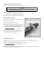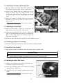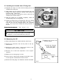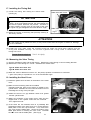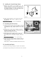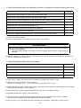
1
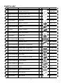
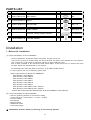
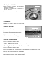
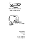
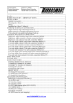
VALCON PLUS V-CAM SYSTEM STEP 1
INSTRUCTION MANUAL
NAME OF PRODUCT
RB26 V-CAM SYSTEM STEP1
USE
AUTOMOBILE PARTS
PART NUMBER
22007-AN002
TYPE A
22007-AN003
TYPE B
MAKE
NISSAN SKYLINE GT-R
ENGINE
RB26DETT
AUG. 1989 - DEC. 1994 (BNR32)
YEAR
JAN. 1995 - DEC. 1998 (BCNR33)
JAN. 1999 - AUG. 2002 (BNR34)
REMARKS
・ Type A cannot be used with an engine which cylinder head's bottom side is
modified.
・ To install Type B, HKS Forged Piston Kit for RB26DETT is required in
addition. (Please see the instruction “Before the Installation” below.)
・ Additional piping for oil is required to install this product.
・ The camshaft for the exhaust side is not included in this kit.
NOTICE
This manual assumes that you have and know how to use the tools and equipment necessary to
safely perform service operations on your vehicle. This manual assumes that you are familiar with
typical automotive systems and basic service and repair procedures. Do not attempt to carry out
the operations shown in this manual unless these assumptions are correct. Always have access
to a factory repair manual. To avoid injury, follow the safety precautions contained in the factory
repair manual.
THIS MANUAL & THIS PRODUCT
● This manual indicates items you need to pay attention to in order to install this product safely and lists
precautions to avoid any possible damage and/or accidents.
● The installation must be done by referring to the factory manual. If the factory manual is not available,
please purchase it from the dealer.
● To use this product on the public road, follow the necessary procedures if there are any regulations for a
tuned vehicle.
● HKS will not be responsible for any damage caused by incorrect use or use after modification and/or
dismantling of this product.
● This product was designed for installation and use on a factory vehicle or a vehicle using other HKS
products. The performance and/or safety cannot be guaranteed if this product is installed onto other
vehicles than mentioned above.
● This product is designed for use in Japan only. It must not be used in any other country.
● The specifications of this product, including installation, components, etc are subject to be changed without
notice.
● This manual is subject to be revised without notice.
PRODUCT CHARACTERISTICS
● This product is to add the variable valve timing system to the RB26 engine. This system continuously
sets the valve timing to the value which was calculated from the preset map utilizing the engine oil's
pressure.
● By changing the intake camshaft's valve timing corresponding to the engine conditions, the slip-back of
the air-fuel mixture made at low-mid RPM can be reduced; it improves the charging rate in the cylinder
and increases the torque. Also, tuning the valve timing and the engine RPM can improve the torque in
all RPM level.
● The increased combustion gas can raise the boost faster even with a large size turbo.
● At idle, the overlap becomes smaller. It stabilizes the combustion, reduces the engine vibration, and
produces a cleaner exhaust gas mixture.
● Type A was designed to work with Nissan stock pistons. The kit works only by replacing the stock
camshaft to HKS V-cam. However, the maximum variable angle was set up to 30°; therefore, Type B
shows better torque improvement at low RPM.
● The maximum variable angle for Type B was set up to 50°; therefore the pistons must be replaced to
HKS Forged Piston Kit. Modification to the cylinder head and/or replacing valve train parts is not
necessary.
USAGAE CONDITIONS
WARNING
Over-Revving may cause damage to the engine.
Avoid over-revving on downshifts, etc.
● Type A was designed to be installed onto the stock engine. Therefore, if the bottom side of the cylinder
head was modified, the cylinder head gasket is thinner, and/or the valve recess is shallower than the
stock, Type A cannot be used.
The following parts are required to use Type B: HKS Forged Piston Kit for RB26DETT (P.N. 2103-RN017, etc)
● The allowable engine RPM to use the stock valve spring is 8,000 rpm.
● The following operations must be done to install this product:
・ Measuring the valve timing
・ Measuring and adjusting the valve clearance
・ Measuring V-P (the clearance between a valve and a piston)
● The following operations must be done to preserve the product's performance and safe use:
・ Setting the fuel injection volume and ignition timing.
・ Correcting the valve timing map
● This product adjusts the valve timing by the engine oil's pressure. In any of the following case, the oil
pressure is decreased the best fuel injection volume and ignition timing cannot be set:
・ The oil pump cannot provide sufficient amount of flow due to too low engine RPM.
・ The low viscosity oil is used.
・ The oil becomes high temperature. The high temperature oil lowers the viscosity and
decreases the oil pressure.
・ The engine oil is degraded.
・ The abrasion of the oil pump widens the clearance.
・ The oil pump inhales air at rapid acceleration or circuit driving.
● When the valve timing variable setting is not sufficient, it's recommended to replace the oil pump to the
large capacity pump such as HKS Oil Pump Upgrade (P.N.2503-RN001).
● This product was developed to improve engine output. Improving engine output may affect the oil and/or
water temperature, the oil pressure, and the fuel volume. To preserve engine performance, maintain engine
conditions when driving.
-1-
PARTS LIST
NO.
PART NUMBER
1
DESCRIPTIONS
Cylinder Head Cover
QT
1
IMAGE
REMARKS
Intake Side
2
G89841-N21010-00 Oil Control Valve ( OCV )
1
3
G89431-N21010-00 Camshaft Angle Sensor
1
4
91112-155100
2
M6 × 14
5
G14532-K00010-00 Adaptor Connector
1
M16-NPT1/8
6
G14539-K00010-00 Oil Filter
1
7
FCM2001
1
8
G11231-N48010-00 Head Cover Gasket
1
9
24003-AK001
1
10
E11210-K00010-00 Name Plate
11
Flange Bolt
Straight Connector
Oil Filler Cap
NPT1/8-AN4
1
Camshaft STEP1
1
248 ° -8.6 ㎜
12
G13574-K00010-00 Flange Bolt w/ Through-hole
1
M12 × 35
13
G14510-N48020-00 Variable Valve Timing Unit A
1
For Type A Only
13
G14510-N48030-00 Variable Valve Timing Unit B
1
For Type B Only
14
G14513-K00010-00 Cover Plate
1
15
G90191-051001-A2 Extra Low Head Cap Screw
3
16
G14532-N48020-00 Oil Line Adaptor
1
17
G14551-N48020-00 Joint Pipe
2
18
G96216-150055-00 O-ring
4
19
G14534-N48020-00 Adaptor Mounting Plate
1
20
G13574-N48040-00 Cam Cap Bolt
4
21
94110-061006
4
Self Lock Nut
-2-
M5 × 10
I.D.I5.5
M6
PARTS LIST
NO.
PART NUMBER
DESCRIPTIONS
QT
IMAGE
REMARKS
22
G90311-062101-0A Plain Washer
4
23
G11335-N48020-00 Spacer
1
24
G91421-700815-C0 Flat Head Bolt
1
M8 × 15
25
G90315-120001-00 Rubber Washer
1
I22 x I12 x 3
1
For RB26 Only
26
27
Controller, Wiring Diagram, Manual
E04121-N48031-00 Instruction Manual
M6
1
Installation
1. Before the Installation
(1) Parts necessary for the installation
・ Oil lines (Diameter should be larger than AN4) and the exit of oil.
The exit of oil must be located after the stock oil filter and where can maintain the oil pressure.
(e.g. Connector of the stock oil pressure sensor or filter replacing type)
The oil filter included in this kit cannot filter small debris. If the exit of oil is in before the stock
oil filter, add a fine meshed filter in the oil line.
Oil resisting hose must be used for oil lines. (e.g. HKS Flexible Hose)
・ To use Type B, use one of following piston kits:
HKS Forged Piston Kit Series for RB26DETT
Part Number: 2103-RN020
Part Number: 2103-RN019
Part Number: 2103-RN021
Part Number: 2103-RN017
Part Number: 2103-RN018
Part Number: 2103-RN013
Part Number: 2103-RN015 (2.8L STEP2)
Part Number: 2103-RN016 (2.8L STEP3)
*Please refer to the instruction attached each kit for the installation of the piston kit.
(2) Tools necessary for the installation
・ Silicone grease (relevant to Three Bond 1855)
・ Torque Wrench ( Torque Spec.: 3.0 Nm - 90 Nm)
・ Vernier Caliper
・ Dial Gauge
・ Magnet Stand
・ Graduation Plate
・ Thickness Gauge
● Installation must be done by referring to the factory manual.
-3-
2. Checking the Included Parts
Type B Only
(1) Check if there is any missing parts or shortage
referring to the parts list.
The pulley for Type B unit has a dimple mark on
the back. (See Fig.1)
(2) Remove all sensors temporarily installed on the
included head cover.
Fig.1
3. Cleaning Parts
(1) Clean the inner of a pipe or adaptor where oil goes through.
4. Replacing Baffle Plate
(1) Remove the baffle plate from the stock head cover.
Make sure not to bend the plate.
Oil Separator
(2) Clean the oil separator and baffle plate.
(3) Fix a bend of the removed baffle plate if necessary.
(4) Apply small amount of liquid gasket to the inside of the
cylinder head; then, insert the oil separator. Secure the
baffle plate with the stock bolt. (See Fig.2)
Fig.2
Liquid Gasket
5. Removing the intake camshaft
(1) Follow the instructions of the factory manual.
(2) Inspect the removed intake camshaft, cam cap, and lifter.
cause is. Replace the parts if necessary.
If any defect is found, make sure what the
6. Confirming the Valve Clearance of the Exhaust Camshaft
(1) Follow the instructions of the factory manual.
(2) Turn the crankshaft and lower the piston from the top dead center so that the exhaust camshaft can be
turned.
(3) Adjust the valve clearance to be within the standard value.
Exhaust Side: 0.35 - 0.41mm (under cold condition)
(4) After the adjustment, leave the exhaust camshaft uninstalled.
-4-
7. Adjusting the Valve Clearance by V-Cam
(1) Follow the instructions of the factory manual to install the V-Cam.
ATTENTION
● When tightening the cam cap, make sure the V-Cam is placed parallel.
If not, the V-Cam may be broken.
(2) Adjust the valve clearance to be within the standard value.
Intake Side: 0.42 - 0.48mm (under cold condition)
(3) Make sure if the V-Cam is rotated smoothly; then remove it.
8. Installing Oil Line Adaptor
(1) Make sure there is no dust and/or scratch on the journal.
Hold the adaptor while tightening the bolt.
(2) Apply engine oil to the journal.
(3) Place the oil line adaptor as shown in Fig.3.
(4) Tighten the bolt with hand till the bolt reaches to the bottom.
Then, hold the mating side of the oil line adaptor from side
to the V-Cam. Tighten the bolt equally at the point where
there is no gap between the cap and the camshaft.
Torque Spec.N ・ m(kgf ・ m )
T=2.7 - 3.3 (0.3)
(5) Make sure the oil line adaptor can be rotated lightly.
If the adaptor does not rotate, reinstall it from the
beginning. If not, it may cause seizure.
Cam Lobe Side
Fig.3
9. Installing the V-Cam
(1) Replace the stock cam cap bolt of the journal #1 and #2 (4 pcs) to the bolts included in the kit.
(2) Follow the instructions of the factory manual to install the V-Cam.
Make sure the oil line adaptor does not get caught in the cylinder head.
Torque Spec.N ・ m(kgf ・ m )
T=9 - 12 (0.92 - 1.2)
(3) Make sure the oil line adaptor does not come in contact with the cylinder head when the mating side is put
together with the upper side of the cylinder head.
-5-
10. Installing the Adaptor Mounting Plate
(1) Set the adaptor mounting plate after making sure
the direction of the plate is correct. (See Fig.4)
Joint Pipe
O-ring x 2
Self Lock Nut
Plain Washer(4 points)
(2) If the oil line adaptor does not rotate at all, it may
come in contact with the cylinder head. If so,
remove the camshaft with the adaptor, and shave
the portion which comes in contact with the cylinder
head.
(3) Install the adaptor mounting plate using the plain
washers (4 pcs) and the self lock nuts (4 pcs).
(See Fig.4)
Torque Spec.N ・ m(kgf ・ m )
T=7 - 8 (0.71 - 0.82)
Adaptor Mounting Plate
11. Installing the Joint Pipe
(Narrow side should face outward)
(1) Clean the joint pipe. Install the O-ring onto the
both ditches of the joint pipe. (See Fig.4)
Joint Pipe
O-ring x 2
Fig.4
(2) Apply silicone grease to the O-rings. Make sure
they can be inserted into the hole on the head cover
side. If the rings cannot be inserted, modify the
edge part of the taper.
(3) Install the joint pipe onto the hole of the oil line adaptor. (Fig.4)
12. Installing the Exhaust Camshaft
(1) Follow the instructions of the factory manual to install the exhaust camshaft.
13. Install the Cam Oil Seal
(1) Apply silicone grease to the inside oil seal; then install it onto the cylinder head.
ATTENTION
●
Do not drive in the oil seal too much. It may cause oil leakage since the length of the portion
the oil seal and the variable valve timing unit are connected is not long enough.
14. Installing the Rear Belt Cover
(1) Remove the grommet and collar of the M8 bolt
attached onto the rear belt cover.
Spacer
(2) Insert the included spacer and install the included
rubber washer. (See Fig.5)
(3) Secure the rear cover using the included dish bolt. (See
Fig.5)
Torque Spec.N ・ m(kgf ・ m )
T=16 - 22 (1.6 - 2.2)
-6-
Rubber Washer (Back)
Fig.5
15. Installing the Variable Valve Timing Unit
(1) Degrease the edge of V-Cam and the mating side of the
variable valve timing unit.
(2) After making sure the dowel pin and the dowel pin hose
position are correct, insert the variable valve timing unit
into the V-Cam. (See Fig.6)
(Since the clearance of the shaft is narrow, insert the unit
carefully not to make scratch.)
Degrease the mating side.
(3) After the dowel pin is inserted completely, install the
included flange bolt w/ through-hole.
(4) Tighten the flange bolt w/ through-hole while the variable
valve timing unit is turned to right slightly and hold it. To
hold the unit, use the octagonal part of the camshaft's
center. Do not put force toward the turning direction on
the unit.
Dowel Pin Hole
Fig.6
Torque Spec.N・ m(kgf・ m)
T=85 - 95 (8.7 - 9.7)
ATTENTION
● Do not loosen the bolt on the back of the variable valve
timing unit. It may cause malfunction to the unit.
16. Measuring the V/P
③ Measure the lift value with
the diale. gauge.
(1) Set the dial gauge to the intake side lifter. (See Fig.7)
(2) Rotate the crankshaft, and set the piston at the top
dead center.
② Rotate the camshaft
till the valve slightly
touches the piston.
(3) Rotate the V-Cam slowly. Note the lift value on the
dial gauge when you feel a response.
(3) Reverse the V-Cam and reposition to the original
position.
(5) Make sure the dial gauge is reset.
① Set the
piston at the
TDC.
(6) For the Type A, the lift value should be more than 4.4mm.
For the Type B, it should be more than 6.7mm.
(7) Remove the dial gauge, and install the exhaust camshaft.
Fig.7
-7-
17. Installing the Timing Belt
(1) Install the timing belt mating the match mark.
(SeeFig.8)
Mate the match mark.
ATTENTION
● Type A was designed to used with the stock pistons;
however, at the most advance angle, the gap between the
valve and the piston becomes very narrow. Therefore, if
the belt's position is wrong even by one tooth of the gear,
the engine may get damaged at the most advance angle.
Make sure the position of the O-ring.
(2) Adjust the tension of the timing belt precisely referring to
the factory manual.
Fig.8
ATTENTION
● If the timing belt is pulled too much, it may cause noise after the engine is started or damage
to the camshaft.
(3) Install the cover plate using the included extra low head cap screw after making sure the
O-ring was installed correctly. Do not use a generic bolt. It may come in contact with the
timing belt cover.
Torque Spec.N ・ m(kgf・ m )
T=2.7 - 3.3 (0.3)
18. Measuring the Valve Timing
(1) Set the graduations plate and the dial gauge. Measure the valve timing in correct rotating direction.
(2) Measure the valve timing at 1 mm lift. Calculate the median value.
Type A ATDC: more than 120°
Type B ATDC: more than 125°
(3) When the value is different more than 10°, the pulley's position is needed to be confirmed.
1 gear of the pulley is equivalent to 15° of the crankshaft's angle.
19. Installing the Head Cover
(1) Install the gasket onto the ditch in the bottom of the head
cover.
(2) Make sure all necessary parts have installed.
Carefully install the head cover placing it parallel to the
cylinder head. Maintain the force onto the head cover not
to damage the O-ring of the joint pipe.
Shave the corners
touch the cam
cover.
(3) Make sure there is no gap between head cover gasket
and the cylinder head.
(4) Make sure positions of the head cover's hole and the
tapped hole in the cylinder head side are matched.
Then, tighten the bolt.
(5) If the holes are not matched, there is a possibility that
somewhere inside of the head cover is in contact with the
baffle plate on the cam cap #3 and #4. If so, remove the
cam cover and the baffle plate. Shave the portion of the
baffle plate which is touching the cam cover. Reinstall
the cam cover and the baffle plate. (See Fig.9)
-8-
Fig.9
20. Installing the Camshaft Angle Sensor
(1) Measure the position of the trigger's tip. The
distance between the mount surface and the tip
should be from 29.5 to 31.0 mm. (See Fig.10) If
the actual distance is not within this range, check
the gasket's condition or if the head cover is in
contact with other parts of the vehicle.
Fig.10
(2) Apply silicone grease to the O-ring; then insert
the camshaft angle sensor. Tighten the bolt.
(See Fig.11)
Torque Spec.N・ m(kgf・ m)
Apply silicone grease.
T=4.5 - 5.5 (0.46-0.56)
Oil Filter
21. Assembling the Oil Flow Parts.
(1) Install the AN4 connector onto the adaptor connector.
The taper screw part is NPT1/8; therefore to avoid
over-tightening, apply piping sealant or use seal
tape.
(2) Reinstall the oil filter and the adaptor connector
following the reverse procedure of disassembling the
temporary installed head cover.
Apply silicone grease to the O-ring.
(3) After applying silicone grease to the O-ring of the oil
control valve (OCV), carefully insert it to the end.
After making sure if the plate sits tightly, install the
bolt.
Torque Spec.N ・ m(kgf ・ m )
Adaptor Connector
Cam Angle Sensor
Oil Contorol Valve
Fig.11
T=7 - 8 (0.71-0.82)
(4) Connect the oil's exit and adaptor connector using oil
piping. Secure the piping not to put excessive force put
on the connection.
Please refer to “1. Before the Installation” about the exit of oil.
22. Assembling the Engine
(1) Reconnect all wiring and piping to replace the camshaft.
(2) Complete wiring referring to the instructions of the controller.
-9-
* Check the following after the installation process is complete and before starting the engine:
CHECK POINTS
CHECK
Make sure the valve clearance is within the standard value range.
Make sure the valve timing is within the designated value range.
Make sure the clearance between the valve and piston is more than the designated value.
Make sure pipes and hoses are routed and connected correctly.
Make sure pipes and hoses are not twisted or bent.
Make sure the level gauge for the engine oil is between H - L.
Make sure all bolts and nuts are tightened.
Make sure installed components are not in contact with other parts of the vehicle.
(1) Check the oil and coolant.
(2) Remove the coupler connecting to the oil control valve (OCV).
ATTENTION
● Once the coupler connecting the oil control valve (OCV), the camshaft's phase
won't be advanced.
To avoid possible damage to the engine, leave the coupler removed until the initial setting is
complete.
(3) Before staring the engine, turn the cell motor on for a few second to increase the oil pressure
without installing the spark plugs.
* Check the following after starting the engine:
CHECK POINTS
CHECK
Make sure oil is not leaking.
Make sure air is not leaking.
Make sure the installed parts are not hitting each other.
Make sure all bolts and nuts are still tightened after stopping the engine.
(1) After idling, change the crank sensor's position and adjust the ignition timing.
(2) Record the angle indicated in the controller.
Make sure the angle is ±5 ゚ of the valve timing measured in sec.17.(2).
(3) After stopping the engine, connect the oil control valve (OCV) and complete the initial setting of the controller
referring to the instructions of the controller.
(4) After restarting the engine, make sure the indicator works when increasing the RPM.
(5) Complete setting of fuel, ignition, and valve timing.
(6) The valve timing is changed when the installing position of the crankshaft's angle sensor is change.
In this case, the resetting of the offset value of the controller is needed.
(7) Do not drive in the high RPM right after installing the camshaft. Breaking-in must be done.
-10-
MAINTENACE
• Daily check-up on the vehicle must be done by the owner.
• Do not conduct any operation not stated in the user's manual. Contact your dealer.
• Choose the appropriate spark plug for your driving conditions. HKS Super Fire Racing Plug is recommended.
Contact your dealer for selection.
• Change the engine oil regularly. Using HKS engine oil is recommended.
• Check the tension and abrasion of the timing belt every 10,000 km.
Pay attention the following while driving and after driving:
• Do Idling or after-idling be done if necessary.
• Do not raise the RPM rapidly or rev the engine a few times while in neutral when the engine is not
warmed up.
• Even after the engine is warmed up, do not rev the engine a few times while in neutral to avoid possible
damage to the engine.
WARNING
• If any leakage (Oil ・ Water) is noticed, do not start the engine.
• While driving, any unusual symptom such as rapid decline of the oil pressure is noticed,
immediately stop driving. Make sure oil is not leaking. If oil is leaking, do not restart
the engine.
・ Contact the dealer for repair the leakage.
・ Follow the dealer ’ s instruction.
If the oil leakage is in a terrible condition, ask the dealer for the temporary measure.
It may cause a fire.
• When any damage or unusual symptom is noticed, do not bring the vehicle to the dealer by driving
to prevent additional damage.
● Do not try to repair the vehicle by yourself. You must consult your dealer for repair.
● Any unusual noise, smell, vibration while driving is noticed, take necessary measure
referring to the factory manual.
-11-