1
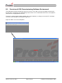
6100 SINGLE LOOP DIGITAL
ADDRESSABLE FIRE ALARM
CONTROL PANEL
PC PROGRAMMING MANUAL
Protec Fire Detection plc, Protec House, Churchill Way, Nelson, Lancashire, BB9 6RT, ENGLAND
+44 (0) 1282 717171
www.protec.co.uk
[email protected]
Document Revision Details
Issue
1
2
3
4
5
Modification Detail
Document Creation
Refer to ECN3414
Addition of T1/T2 output group delays
Addition of 'Cancel all delays in night mode'
Refer to ECN3477
VAD description added to section 2.0
Figure 13.0 updated
Figure 13.4 updated
Section 13.13 updated
Section 10.11 added
Section 15 updated
Addition of FBP setup information (section
11.0 expanded, section 13.19 and 13.20
added)
N93-531-79 Issue 5 NH
Page 2 of 33
Author
NH
NH
Date
20/06/2012
10/10/2013
NH
17/03/2014
NH
22/06/2014
NH
14/07/2015
© Protec Fire Detection plc 2015
Table of Contents
1.0
IMPORTANT NOTES – PLEASE READ CAREFULLY ........................................................................ 5
2.0
GLOSSARY OF TERMS ........................................................................................................................ 6
3.0
INTRODUCTION .................................................................................................................................... 8
4.0
INFORMATION REQUIRED PRIOR TO COMMISSIONING ................................................................. 9
4.1
5.0
Site Specific Information Required to Commission the 6100 .......................................................... 9
ITEMS REQUIRED TO COMMISSION THE 6100 USING A PC ........................................................... 9
5.1
5.2
PC / Laptop Requirements .............................................................................................................. 9
Software and Hardware Requirements ........................................................................................... 9
6.0
LOADING THE 6100 COMMISSIONING SOFTWARE ONTO A PC .................................................. 10
7.0
CONNECTING AND DISCONNECTING THE 6100 FROM THE PC .................................................. 10
7.1
7.2
8.0
Connecting the PC to the 6100 ..................................................................................................... 11
Disconnecting the PC from the 6100 ............................................................................................. 11
OVERVIEW OF 6100 COMMISSIONING SOFTWARE ENVIRONMENT ........................................... 12
8.1
8.2
8.3
8.4
8.5
9.0
The file menu ................................................................................................................................. 13
The Edit menu ............................................................................................................................... 13
The View menu .............................................................................................................................. 14
The Panel menu ............................................................................................................................ 14
The Help menu .............................................................................................................................. 14
CREATING A SITE FILE ...................................................................................................................... 15
9.1
9.2
9.3
10.0
Creating a Blank Site File .............................................................................................................. 15
Creating a Site File Using the Loop Commissioning Booklet ........................................................ 15
Creating a Site File by Logging and Mapping Devices Directly on the 6100 ................................. 16
PROGRAMMING LOOP DEVICE DATA ......................................................................................... 16
10.1
10.2
10.3
10.4
10.5
10.6
10.7
10.8
10.9
10.10
10.11
11.0
PROGRAMMING CAUSE AND EFFECT SEQUENCES ( MATRIX ) ............................................. 20
11.1
11.2
11.3
11.4
11.5
11.6
12.0
Allocating a Zone Number to a Loop Input Device .................................................................... 16
Allocating an Input Group to a Loop Input Device ..................................................................... 16
Allocating an Output Group to a Loop Output Device ............................................................... 16
Allocating an Output Group to the Conventional Alarm Outputs ............................................... 16
Programming Loop Sounder Volume Levels ............................................................................. 17
Allocating a Class to a Loop Device .......................................................................................... 17
Setting a Loop Input Device to be Latching or Non-Latching .................................................... 17
Setting Automatic Detector Sensitivities .................................................................................... 18
Programming Display Group Data ............................................................................................. 18
Programming Repeat Group Data ............................................................................................. 18
Programming the coverage volume of a Visual Alarm Device (VAD) type ................................ 19
Setting up the Output Group Activation Tone ............................................................................ 20
Setting up the Output Group Activation Tone when FBP mode is enabled ............................... 20
Setting up Output Group Delays (T1 and T2) ............................................................................ 20
Programming the Output Group Type ....................................................................................... 21
Sound Alarms, Remote Alarm and Class Change Programming .............................................. 21
Setting up Coincidence Operation ............................................................................................. 22
ENTERING DEVICE, ZONE AND PANEL TEXT ............................................................................. 23
N93-531-79 Issue 5 NH
Page 3 of 33
© Protec Fire Detection plc 2015
13.0
PROGRAMMING PANEL CONFIGURATION DATA ...................................................................... 24
13.1
13.2
13.3
13.4
13.5
13.6
13.7
13.8
13.9
13.10
13.11
13.12
13.13
13.14
13.15
13.16
13.17
13.18
13.19
13.20
Programming the Panel Access Codes ..................................................................................... 24
Programming the Global Fire and Fault Contact Operation ...................................................... 24
Programming the Fire Link Activation Delay.............................................................................. 25
Programming the Fire Link Search Time ................................................................................... 25
Programming a First Knock Fire Link Delay Time ..................................................................... 25
Programming the Walk Test Timeout ........................................................................................ 25
Programming Talking Sounder Options ..................................................................................... 26
Programming the Pulsing Alarm Timeout and Tone .................................................................. 26
Programming the System Pulsing Alarm Times ........................................................................ 26
Programming Day and Night Times ........................................................................................... 27
Programming Remote Alarm Operation .................................................................................... 27
Programming Class Change Operation ..................................................................................... 27
Programming Loop Beacon and VAD Operation ....................................................................... 27
Overriding System Delays on a Second Knock Coincidence Activation ................................... 28
Pulsing the First Display Group into Alarm ................................................................................ 28
Programming Loop Devices to ‘Flash when Polled’ .................................................................. 28
Programming Dual Fire Link Outputs ........................................................................................ 28
Cancelling Delays in 'Night' mode ............................................................................................. 28
Enabling Fire Brigade Panel (FBP) Operation ........................................................................... 28
Disabling the LCD when in FBP Mode ...................................................................................... 28
14.0
VIEWING HISTORIC EVENT LOGS ................................................................................................ 29
15.0
UPLOADING AND DOWNLOADING SITE FILES TO THE 6100 ................................................... 29
15.1
15.2
15.3
16.0
Uploading a Site File from the 6100 .......................................................................................... 29
Downloading a Site File to the 6100 .......................................................................................... 29
Updating the 6100 Operating System ........................................................................................ 29
THE HELP MENU ............................................................................................................................. 30
16.1
16.2
16.3
Generating an Emergency Code ( ECode ) ............................................................................... 30
Checking For Updates to the Commissioning Software ............................................................ 30
Downloading Online Documentation ......................................................................................... 30
N93-531-79 Issue 5 NH
Page 4 of 33
© Protec Fire Detection plc 2015
1.0
Important Notes – PLEASE READ CAREFULLY
•
The 6100 fire alarm control panel and its associated connections must be installed,
commissioned and maintained by a suitably skilled and competent person.
•
It is assumed that the person commissioning the system is aware of fire alarm equipment
terminology and terms of reference.
•
This equipment must be earthed.
•
This equipment is not guaranteed unless installed and commissioned in accordance with current
national standards.
•
This equipment has been designed and manufactured to conform to the requirements of all
applicable EU council directives and regulations.
•
Both the 6100 User manual, 6100 Installation and Commissioning manual and this manual must
be thoroughly read and understood before programming is undertaken.
•
This equipment WILL NOT operate as a fire alarm panel when the USB port is connected and the
panel is connected to a PC.
•
This equipment is not suitable as part of an I.T type power distribution system as defined in
IEC 60364-3.
•
There are no user serviceable parts inside the 6100 panel. A competent person trained to
undertake such work MUST carry out any internal maintenance work.
The policy of Protec Fire Detection plc is one of continuous improvement and as such we reserve the right to
make changes to product specifications at any time and without prior notice.
Errors and omissions excepted.
N93-531-79 Issue 5 NH
Page 5 of 33
© Protec Fire Detection plc 2015
2.0
Glossary of Terms
‘6100’ or ‘panel’
Refers to the 6100 fire alarm control panel.
Downloading
Refers to the transfer of data from a PC to the 6100.
Uploading
Refers to the transfer of data from the 6100 to a PC.
Site-file
Refers to the site configuration data file that is stored the 6100, this file contains the data about loop devices,
panel settings, loop device text, zone text, panel text and cause and effect ( matrix ) information. When this
file is uploaded using the Windows commissioning software any historic event logs are automatically
appended to it.
Incomplete and complete site files
Some elements of loop device data can only be retrieved when the loop devices are logged and mapped
( loop device software version and map node are two examples ). A site file that has not yet had this data
stored is termed ‘incomplete’. This type of site file is generally produced when scanning device data from
barcode labels on the devices, an incomplete site file must be downloaded into the 6100, the loop logged
and mapped and the file uploaded after which it will be ‘complete’ and can be backed up.
Input Group
Input devices ( detectors, Manual Call Points, MIP’s etc. ) must be allocated an input group in the range
1 to 31. The input group triggers the cause and effect’s sequences and is linked to activate output devices by
relevant programming in the cause and effect matrix.
Output Group
Output devices ( sounders, MICCO’s etc ) must be allocated an output group in the range 1 to 32. The output
group is activated by input group activations as dictated by relevant programming in the cause and effect
matrix.
Devices programmed into alarm output groups are triggered under a ‘Sound Alarms’ condition and are
silenced when ‘Silence Alarms’ is pressed.
Devices programmed into control output groups are not triggered under a ‘Sound Alarms’ condition and are
not silenced when ‘Silence Alarms’ is pressed. A panel reset is required.
Zone
Input devices must be allocated a zone number in the range 1 to 32.
Matrix
The system programming describing how output groups are triggered by input groups.
Class
The device class determines how the 6100 will process an activation from that device. Each input device
may be allocated a class. Detectors are programmed as ‘automatic’ class, whereas Manual Call Points are
programmed as ‘manual’ class. See section 10.6 for more details.
Display Group
The Protec 6000/MIMIC device controls LEDs and can be used as a geographical mimic indicating where
input devices have activated. Loop input addresses may be allocated a display group in the range 1 to 255
( 0 disables the feature ) if the input device activates, the corresponding display group LED illuminates on the
mimic.
For example, if input device 10 was allocated a display group of 34, LED 34 on the Protec 6000/MIMIC
would illuminate if input device 10 activated.
N93-531-79 Issue 5 NH
Page 6 of 33
© Protec Fire Detection plc 2015
Repeat Group
Loop devices may be allocated a repeat group in the range 1 to 32 ( 0 disables the feature ). The repeat LED
on the device ( usually an automatic detector ) is switched on if an output group matching the programmed
repeat group activates. For example if loop device 25 has its repeat group programmed to 6, then the repeat
LED on address 25 will illuminate if output group 6 activates.
Non-latching
A non latching device returning to normal will cause the 6100 to automatically reset ( if no other latching
activations are present ). An activation from a latching device requires the 6100 to be manually reset.
Day and Night Sensitivity Levels
Each automatic detector can have day and night sensitivities programmed. The sensitivity level controls how
the device reacts to smoke, heat or carbon monoxide and can be used to tailor the response of the device to
match specific site conditions ( to minimise false activations due to steam from showers, for example ).
Coincidence
The 6100 can automatically activate extra input groups when two, or more devices trigger ( coincidence ) in
a specific input groups, or across any input groups ( global coincidence ).
Open Protocol System
If the system is Open Protocol the commissioning software freely connects to the 6100 and allows full access
to all programming features. There is no need for a USB dongle.
Managed System
If the system is managed, then a dongle is required ( available from Protec ) to access all features in the
commissioning software. Without a dongle, or with an incorrect dongle fitted, the commissioning software will
not connect to the 6100.
Automatic Device
Automatic devices are smoke, heat or carbon monoxide detectors ( or a combination of these ) which
automatically activate the 6100 when the sensed level exceeds a pre-determined set point.
Manual Device
This device type requires manual intervention in order to activate it and cannot automatically activate the
6100. The most common example of this is a Manual Call Point.
The 6100 processes this device class differently to an automatic device. Any programmed delays are usually
overridden when the activation signal from a manual device is received.
Dongle
A piece of hardware used on managed systems which is connected to the PC USB port. Commissioning
software connection is restricted to 6100 panels containing a matching code to the Dongle, therefore limiting
panel access to engineers with relevant dongles.
VAD
An acronym for Visual Alarm Device, which is a high intensity 'beacon' designed to comply with EN54-23.
FBP
An acronym for Fire Brigade Panel, which is typically used for Australian markets. When the panel is set to
this mode via the Windows PC software the 6100 then expects a FBP interface to be fitted.
N93-531-79 Issue 5 NH
Page 7 of 33
© Protec Fire Detection plc 2015
3.0
Introduction
The Protec 6100 Fire Alarm Control Panel has been designed and manufactured in the United Kingdom. The
6100 complies fully with current standards dictating fire alarm system design practice ( EN54 parts 2 and 4 ).
The 6100 panel is a single loop fire alarm control panel incorporating an on-board power supply and high
power loop driver circuitry that allow communication to a maximum of 192 Protec 6000Plus series devices.
This manual is concerned with how the 6100 system is commissioned using the software suite specifically
designed by Protec for the purpose. It is assumed the commissioning engineer is familiar with standard
addressable fire alarm system operation and terms of reference.
The 6100 Commissioning Software allows the commissioning engineer to perform the following functions.
•
Downloading the 6100 operating system firmware.
•
Open, edit and download site files.
•
Create site files by scanning in loop device data using a barcode scanner.
•
Upload the current site file from the 6100 for backup, or printing.
•
Edit / enter device, zone and panel text.
•
Upload fire and non-fire historic logs.
•
Import device, zone and panel text from a Microsoft Excel spreadsheet
( using the Excel™ text editor program developed by Protec ).
N93-531-79 Issue 5 NH
Page 8 of 33
© Protec Fire Detection plc 2015
4.0
Information Required Prior to Commissioning
4.1
Site Specific Information Required to Commission the 6100
To ensure rapid and trouble-free commissioning the following information must be supplied to the
commissioning engineer or company in advance of the proposed commissioning date.
•
•
•
•
•
6100 Loop Commissioning Booklet ( filled in with device data & loop addresses ).
Loop device address text ( 20 characters maximum per device ).
Zone text ( 20 characters per zone maximum ).
Panel text ( 2 lines of 20 characters maximum ).
Required cause and effect programming ( matrix information, delays, coincidence data etc.).
A commissioning form is available upon request which should be filled in with the relevant information.
5.0
Items Required to Commission the 6100 Using a PC
5.1
PC / Laptop Requirements
The PC used to connect to the 6100 must conform to the following minimum specification.
•
•
•
•
•
•
•
5.2
1 GHz processor.
1 GB RAM.
1 GB available hard disk space.
One free USB 2.0 communications port ( for connection to the 6100 ).
A second free USB 2.0 communications port ( if a Dongle is required ).
®
®
Windows Operating System XP, Vista, or Windows 7 ( 32 bit or 64 bit ).
Connection to the internet ( if online software updates are required ).
Software and Hardware Requirements
•
6100 commissioning software ( with a suitable dongle if the site is managed ).
•
USB barcode scanner ( CipherLab 1000 CCD, or equivalent ).
•
T15 Torx™ type security tool ( for removal of the 6100 enclosure front cover ).
•
USB Lead ( Type A male to Type B male, as illustrated below ). 2 metres maximum length.
TYPE A
N93-531-79 Issue 5 NH
TYPE B
Page 9 of 33
© Protec Fire Detection plc 2015
6.0
Loading the 6100 Commissioning Software onto a PC
The 6100 commissioning software is supplied as a single executable file following the naming convention
‘6100 PC VX.XX.exe’ , no special installation is required and the file is simply copied onto the desktop of the
PC being used for commissioning.
If the PC is connected to the internet the 6100 commissioning software may check to see if a newer version
is available. If so, a warning box is displayed asking if an upgrade should be carried out. Only click ‘yes‘ if
you are sure an upgrade to the commissioning software is required.
7.0
Connecting and Disconnecting the 6100 from the PC
When the front cover of the 6100 is removed all system cabling, including mains cabling and
connections are accessible. DO NOT touch any connections or cabling.
The PC connects to the 6100 using a standard USB cable ( see section 5.0 ). The USB port on the 6100 is
accessed by removal of the enclosure front cover, as shown in figure 7.0.
3
USB port location
2
1
Figure 7.0. Removal of 6100 enclosure front cover, and USB connection to a PC
N93-531-79 Issue 5 NH
Page 10 of 33
© Protec Fire Detection plc 2015
7.1
Connecting the PC to the 6100
The USB communication port is located on the centre left of the 6100 PCB housing ( see figure 7.0 ).
Ensuring the 6100 is powered up connect the USB cable to a free USB port on the host PC, then carefully
plug the other end of the USB cable into the USB port on the 6100.
Using the menus on the 6100 ( consult the 6100 Installation and Commissioning Manual ) select the
CONNECT TO PC USING USB option and press the ↵ key to enter the menu.
When the 6100 panel is connected to the PC it WILL NOT operate as a fire alarm panel.
At the warning screen press the ↵ key to continue, or to exit press any of the ▲, ▼, ◄ or ► keys.
Note: When the 6100 is connected to a PC for the first time the PC must recognise the 6100 and load
appropriate software drivers, this can take up to 1 minute. Standard Windows drivers are used, no special
drivers are required. Further connections to the same PC will not require this phase.
Once connected to a PC the 6100 will display its PC connection screen, all further control is now performed
using the PC only.
7.2
Disconnecting the PC from the 6100
When all commissioning has been completed the following procedure must be followed to correctly
disconnect the PC from the 6100.
•
Close the 6100 commissioning software.
•
Disconnect the 6100 from the PC by using the Windows ‘ Safely Remove Hardware ‘ feature.
•
Carefully remove USB lead from the 6100.
®
The 6100 automatically detects the USB lead has been removed and resets. The loop will be
re-powered and a full loop re-initialisation sequence will be instigated.
The reboot process may take up to 1 minute, during which time the 6100 may not respond to
fires or faults.
N93-531-79 Issue 5 NH
Page 11 of 33
© Protec Fire Detection plc 2015
8.0
Overview of 6100 Commissioning Software Environment
The 6100 commissioning environment consists of a main screen with several menu options located at the
top left corner. Selecting a menu option brings it to the main screen. Information entered in a menu option is
retained when swapping between menus.
To open the commissioning software double click on the 6100 icon ( usually present on the PC’s desktop ).
The main screen will open as illustrated in figure 8.0.
Figure 8.0 Main screen and sub options
N93-531-79 Issue 5 NH
Page 12 of 33
© Protec Fire Detection plc 2015
8.1
The file menu
This menu contains the following choices:
New
This option creates a default site file where all aspects of the programming are restored to their default
settings. This must be done before creating a new site file, or before scanning data in from device bar codes.
Load
This option loads a previously saved site file. The user must navigate to the file and open it. All site files have
the .psf file extension.
Import Text
Text previously exported from the Protec Excel text editor can be imported into the site file using this
function.
Save / Save As
Allows the site file currently loaded to be saved ( as filename.psf ).
Export
This option allows the Event log, Device Data, Matrix and Text to be exported to a .txt file.
Exit
Exits the program.
8.2
The Edit menu
This menu contains the following choices:
Enter Site Info
This screen allows information about the site to be entered. The data is then stored in the panel and can be
retrieved at a later date.
Matrix Editor
The cause and effect matrix is edited in this window, output group activations are linked to input group
activations. Output group delays and type can also be setup and the conventional alarm output group can be
programmed.
Text Editor
The loop device text, zone text and panel text can be entered and edited in this screen.
Device Editor
Loop device data and operational parameters are setup in this screen.
Coincidence
Input group coincidence operation is enabled and programmed in this screen.
Panel Information
Various system operational parameters are setup in this screen, including User and Engineer access codes,
global relay operation, fire link delay times, fire link search time, talking sounder messages and
synchronisation time.
N93-531-79 Issue 5 NH
Page 13 of 33
© Protec Fire Detection plc 2015
8.3
The View menu
This menu allows the user to view event logs uploaded from a panel, or stored in a site file.
8.4
The Panel menu
This menu is used to download and upload data to and from the 6100, to update the operating system
firmware or to change the panel from managed to open protocol ( relevant dongle must be installed ).
8.5
The Help menu
This menu allows the user to generate an emergency access code ( if the entry codes for the 6100 have
been forgotten ), check for updates to the commissioning software or download relevant 6100 documentation
from the internet.
N93-531-79 Issue 5 NH
Page 14 of 33
© Protec Fire Detection plc 2015
9.0
Creating a Site File
9.1
Creating a Blank Site File
When starting from scratch a blank ( default ) site file must be used. This site file contains default values for
relevant elements of the site data.
To create a blank site file click
File -> New
then select ‘Yes’ when the program requests to Delete Current Settings. A default site file will be loaded into
the program.
9.2
Creating a Site File Using the Loop Commissioning Booklet
In some cases it is advantageous to build the site file remotely from the panel ( a site file can be prepared
before visiting site if loop device data, matrix and associated text is known before hand ).
All Protec loop devices are supplied with two manufacturing barcode labels. During installation one label
remains on the device and the other is removed from the device and affixed at the relevant loop address in
the 6100 Loop Commissioning Booklet. This then links the device to a loop address.
In the Edit -> Device Editor window of the commissioning software the 6100 Loop Commissioning Booklet
is then used in conjunction with a barcode scanner to scan the address number in the booklet followed by
the loop device data. This device data is then stored at the relevant address. See figure 9.0.
The extra device parameters ( input group, output group, class etc. ) can be edited at this point if desired.
Tip
Devices with more than one serial number ( 16 way products, for example ) may be entered by repeated
scanning of the serial number barcode, the 6100 commissioning software will automatically increment the
address and serial number on each scan.
Note that when using this method the software version and map node for the loop device are not
read from the barcode label ( the site file is incomplete ).
When all devices have been scanned in from the Loop Commissioning Booklet the site file must be
downloaded into the 6100 and the loop logged and mapped, at this point the software version and
map node are added to the site file ( it becomes a complete site file ) and it must be uploaded from
the 6100 for backup purposes.
Figure 9.0
Example of device serial
number 0x74249F allocated
to address 2.
N93-531-79 Issue 5 NH
Page 15 of 33
© Protec Fire Detection plc 2015
9.3
Creating a Site File by Logging and Mapping Devices Directly on the 6100
The alternate method for creating a site file is to log and map loop devices on the 6100, then upload the site
file into the commissioning software. Any loop device parameters or panel options may then be edited as
required and the file downloaded into the 6100.
10.0 Programming Loop Device Data
Loop device data programming is done in the Edit -> Device editor window.
10.1
Allocating a Zone Number to a Loop Input Device
Loop input devices must be allocated a zone number in the range 1 to 32. The zone number required will
depend on where the device is physically located on site. Usually ‘as fit’ drawings are available detailing this
information. Click on the zone field of the relevant loop address and enter the zone number.
10.2
Allocating an Input Group to a Loop Input Device
Loop input devices must be allocated an input group number in the range 1 to 31. The input group number
required will depend on how the system designer wishes the system to respond when the input group is
activated ( linked by programming in the cause and effect matrix, see section 11.0 ). Click on the Input
group field of the relevant loop address and enter an input group number.
Note that, if enabled, the Remote Alarm input occupies input group 31, which is then unavailable for
use by loop input devices. Similarly, if the Class Change input is enabled input group 30 is
unavailable.
10.3
Allocating an Output Group to a Loop Output Device
Loop output devices ( sounders, beacons, CCOs etc. ) must be allocated an output group in the range
1 to 32. The output group number required will depend on how the system designer wishes the system to
respond when an input group is activated ( linked by programming in the cause and effect matrix, see
section 16.0 ). Click on the Output group field of the relevant loop address and enter an output group
number.
Non-talking and talking loop devices must not be programmed into the same output group.
10.4
Allocating an Output Group to the Conventional Alarm Outputs
The conventional alarm outputs on the 6100 are designed to drive standard 24V output devices. In the
Edit -> Matrix editor window a section is provided to map an output group to the conventional alarm
outputs. By doing this the conventional outputs will follow programming associated with the chosen output
group as shown in Table 10.0.
Table 10.0
Output Group Activation
Conventional Alarm Response
Off
Switches off
Continuous
Switches to 24V
Warble
Switches to 24V
Intermittent ( pulsing )
Alternates between 24V and off at
the system pulsing rate
N93-531-79 Issue 5 NH
Page 16 of 33
© Protec Fire Detection plc 2015
10.5
Programming Loop Sounder Volume Levels
Most Protec loop sounder devices can have their volume levels individually programmed from the 6100. The
selections currently available are LOW, MEDIUM and HIGH. Please consult the specific datasheet for the
loop device to determine the dB output for each volume level.
In the Edit -> Device editor window repeated clicking on the Volume field for the relevant loop address
scrolls through the available choices.
10.6
Allocating a Class to a Loop Device
The activation behaviour of loop input devices can be altered by selecting the relevant option in the Class
field for that address. In general, detectors are set to automatic class and Manual Call Points are allocated
as manual class. Normally 6000/MIP devices are used to control various panel functions via the loop.
In the Edit -> Device editor window repeated clicking on the Class field for the relevant loop address scrolls
through the available class choices.
Table 10.1 details how the class should be allocated to various loop devices.
Table 10.1
Loop Input Device
Class
Operation
Automatic Detector
Automatic
Processed as an automatic device
Manual Call Point
Fast Response Interface
Manual
Processed as a manual device
Silence
Activation causes 6100 to silence
Reset
Activation causes 6100 to reset ( silence must be done first )
Sound Alarms
Activation causes 6100 to sound alarms
Accept
Activation causes 6100 to accept ( mute buzzer )
IReset
Activation causes 6100 to reset ( silence not required )
Automatic
Processed as an automatic device
MIP
Other
10.7
Setting a Loop Input Device to be Latching or Non-Latching
Loop input devices can be set as latching or non-latching. A latching device, once activated, can only be
reset from the 6100 ( by pressing Silence, then Reset at access level 2 or above ).
Non-latching devices cause the 6100 to automatically reset when they return to normal after being activated.
Note that the 6100 will only automatically reset if no other activations are present on the system. If several
non-latching devices are active, the 6100 will only reset when all devices have returned to the normal state.
N93-531-79 Issue 5 NH
Page 17 of 33
© Protec Fire Detection plc 2015
10.8
Setting Automatic Detector Sensitivities
Automatic detectors can be allocated various sensitivity levels, these are used to tailor the response of the
detector to local site conditions ( to minimise unwanted alarms due to steam in a shower, for example ). Two
sensitivity levels can be setup, Day sensitivity and Night sensitivity. Table 10.2 gives suggested applications
for each sensitivity.
The Day sensitivity is used when the 6100 is running in Day mode and is the sensitivity normally used. Night
sensitivity is used when the 6100 is in Night mode and is considered the alternate sensitivity.
To alter the sensitivity of a loop device at a particular address go to the Edit -> Device editor window.
Repeated clicking the Day Sens or Night Sens field for the loop address scrolls through the available
sensitivity selections for that device type.
Loop addresses set with an invalid sensitivity will generate a device fault on the 6100.
Table 10.2
Sensitivity
Suggested Applications
None
Only used for non automatic detector types
Office
The default sensitivity. Used for most applications
Bedroom
Incorporates an anti-steam algorithm for use in bedrooms
Enhanced
Increases the sensitivity of the optical and/or heat sensing element of the detector
Prison
Used specifically for prison cells
10.9
Programming Display Group Data
The 6000 loop mimic device is designed to offer a loop driven geographic mimic function. The device drives
up to 255 LEDs which can be mapped to an individual loop address activation by setting the Display Group
number for that address.
The Display Group number ranges from 1 to 255 ( a Display Group of 0 disables the feature for
that address ). If that loop address activates the 6100 will illuminate the mimic LED corresponding to the
Display Group allocated to that address.
For example, if loop address 25 is allocated a Display Group of 54 then LED 54 of the 6000/MIMIC will
illuminate upon activation of address 25. The mimic LED is cleared on a 6100 reset.
10.10 Programming Repeat Group Data
In addition to the standard indicating LED, all Protec automatic detectors have the ability to control a
separate repeat LED ( consult the datasheet for the specific product for connection details ).
Each loop address on the 6100 can be allocated a Repeat Group in the range 1 to 32. The Repeat Group
number is related to an 6100 output group activation ( output groups range from 1 to 32 ).
If an output group matching the Repeat Group for an address is active ( i.e. not OFF ) then the repeat LED
on the loop address will illuminate.
For example, if loop address 54 has an Repeat Group of 12, then if output group 12 is active ( not OFF )
then the 6100 will illuminate the repeat LED on loop device address 54.
Fire activations of a loop device will always illuminate the repeat LED irrespective of the Repeat
Group setting for that address.
Any output group delays are ignored for Repeat Group processing
N93-531-79 Issue 5 NH
Page 18 of 33
© Protec Fire Detection plc 2015
10.11 Programming the coverage volume of a Visual Alarm Device (VAD) type
If VAD devices are present on the system, the commissioning software permits the coverage volume for
each device to be configured.
The coverage volume of each device must adhere to the requirements of the system design.
The coverage options allow the system designer to balance VAD coverage volume and average loop alarm
current. This means the system is not limited solely to high power VADs, and more VAD devices may be
placed on the loop if less coverage can be tolerated.
Three configuration choices are offered for both ceiling and wall VADs, and the format of the settings in the
commissioning software follows the EN54-23 format T-H-W, where T is the type of VAD (C for ceiling, W for
wall and O for Open class), HH is the required mounting height of the VAD in metres, and WW is the width of
coverage in metres.
For example, a C-3-3 device is a ceiling mounted VAD which is to be mounted on a 3m height ceiling, and
will provide coverage in a 3m diameter cylinder.
A W-2.4-5 device is a wall mounted VAD which is to be mounted 2.4m from the floor, and provides a 5m
cuboid pattern coverage.
Please consult the relevant installation leaflet for the particular VAD for further details.
Clicking in the coverage cell will scroll round the available settings for the loop VAD at that address.
Figure 10.0
Example of a ceiling
mounted VAD set to 3m
coverage diameter.
N93-531-79 Issue 5 NH
Page 19 of 33
© Protec Fire Detection plc 2015
11.0 Programming Cause and Effect Sequences ( Matrix )
Cause and effect sequences are setup by relevant programming of the 6100 matrix. To enter the matrix
editor follow Edit -> Matrix editor.
A window will open showing a matrix of input groups ( down the left hand side of the window ) and output
groups ( along the top of the window ).
11.1
Setting up the Output Group Activation Tone
How an output group activates from an input group trigger is dictated by the letter placed in the relevant cell.
Figure 10.0 shows example matrix settings for input groups 1, 2, and 3.
Placing the cursor over a cell and clicking causes the cell choice to scroll through C ( continuous ), O ( off ),
P ( pulsing ), and W ( warble ).
Activation of output groups always follows the C, W, P, O order of precedence. So, for example, if an output
group was activated as W by input group 2, then input group 1 triggered (which is set to C), the output group
would switch from warble to continuous operation.
11.2
Setting up the Output Group Activation Tone when FBP mode is enabled
How an output group activates from an input group trigger is dictated by the letter placed in the relevant cell.
Figure 10.0 shows example matrix settings for input groups 1, 2, and 3.
Placing the cursor over a cell and clicking causes the cell choice to scroll through C ( evacuate tone ),
O ( off ), P ( alert tone ). Note that W must NOT be selected.
Activation of output groups always follows the C, W, P, O order of precedence. So, for example, if an output
group was activated as P by input group 2, then input group 1 triggered (which is set to C), the output group
would switch from the alert tone to the evacuate tone.
11.3
Setting up Output Group Delays (T1 and T2)
Each output group can have two delays introduced. Delay 1 is termed 'Output Delay T1' and delay 2 is
termed 'Output Delay T2'.
When an output group is activated the activation of the relevant output group can be delayed by up to 10
minutes for T1, and up to 20 minutes for T2. The delays can be set in increments of 5 seconds.
If an output group activation changes from OFF to ON ( C, P or W is classed as 'on' ) the change will not be
actioned until the programmed delay time has expired. Figure 11.0 shows output group 1 set with a T1 delay
of 1 minute and a T2 delay of 5 minutes.
The T1 delay is introduced automatically, and T1 is replaced by T2 delay (if T2 is longer than T1) if the
'Mute Buzzer' button is pressed at access level 2 or 3 during an alarm condition.
Pressing ‘Silence’ before the delay has expired will prevent the output group from becoming active, until the
next activation for that output group
T1/T2 delays will be cancelled by activation of a manual class device, or if the 6100 is in night mode
(and the 'Cancel Delays in Night Mode' option has been selected in the Windows software).
Delays are not used when in 'Walk Test' mode.
N93-531-79 Issue 5 NH
Page 20 of 33
© Protec Fire Detection plc 2015
Figure 11.0
11.4
Programming the Output Group Type
Outputs groups may be of type alarm or control. Alarm output groups usually control devices such as
sounders and beacons. Control output groups can be used to signal to output interfaces ( CCOs, for
example )
Alarm and Control output group activation differences are shown in table 11.0
Table 11.0
Alarm Output Group
Control Output Group
Input Group Activation
Activates as per matrix
Activates as per matrix
Sound Alarms Activation
Activates as per matrix
Does not activate
Silence Alarms
Silences
Does not silence
Walk Test
Activates as per matrix
Does not activate
Reset
Resets
Resets ( turns off )
11.5
Sound Alarms, Remote Alarm and Class Change Programming
The upper input groups are reserved for the Sound Alarms, Remote Alarm and Class change programming.
Sound Alarms has a dedicated line on the matrix, whereas Class Change and Remote Alarm occupy input
groups 30 and 31 respectively only when they are enabled ( via the Edit -> Panel info window ).
When Class Change or Remote Alarm are enabled the matrix displays ‘Class Change’ in place of IPG30 and
‘Remote Alarm’ in place of IPG31. The relevant input group ( 30 or 31 ) is then not available for normal use
in the device editor, and a warning will be issued by the program should the user attempt to allocate one of
these input groups to a loop device.
If loop devices are already allocated to input groups 30 or 31, then the option to enable the Class Change or
Remote Alarm inputs is not allowed.
Figure 11.1 shows the matrix when both the Class Change and Remote Alarm inputs are enabled.
Figure 11.1
Class Change,
Remote Alarm and
Sound Alarms matrix
lines
N93-531-79 Issue 5 NH
Page 21 of 33
© Protec Fire Detection plc 2015
11.6
Setting up Coincidence Operation
The 6100 offers coincidence programming to EN54-2 ( Type C Dependency ).
Using the Edit -> Coincidence open the coincidence programming window ( as illustrated in Figure 11.2 )
Choose the required number of coincidence input groups by clicking on the relevant ‘Number of Groups’
field, the illustration in Figure 11.2 shows 2 coincidence groups selected.
Global Coincidence
If the Number of Groups is set to 1, then global coincidence is enabled. As well as processing the matrix
associated with its own input group, further activations from any input group in the range 2 to 12 will also
trigger input group 28.
Input Group Specific Coincidence
If the Number of Groups is chosen to be between 2 and 12 that range of input groups are programmed as
coincidence. As well as activating programming associated with the input group, two, or more activations
from the same input group will trigger a coincidence group as detailed in figure 11.2.
Examples.
‘Number of Groups’ set to 2
A single activation from input group 1 will trigger matrix processing associated with input group 1, further
activations from devices in input group 1 will trigger matrix processing associated with input group 28.
A single activation from input group 2 will trigger matrix processing associated with input group 2, further
activations from devices in input group 2 will trigger matrix processing associated with input group 27.
‘Number of Groups’ set to 7
A single activation from input group 3 will trigger matrix processing associated with input group 3, further
activations from devices in input group 3 will trigger matrix processing associated with input group 26.
A single activation from input group 7 will trigger matrix processing associated with input group 7, further
activations from devices in input group 7 will trigger matrix processing associated with input group 22.
‘Number of Groups’ set to 1 ( Global Coincidence )
A single activation from an input group will trigger matrix processing associated with that input group, further
activations from devices in input groups 2 to 12 will trigger matrix processing associated with input group 28.
Figure 11.2 Illustration of 2 coincidence groups.
N93-531-79 Issue 5 NH
Page 22 of 33
© Protec Fire Detection plc 2015
12.0 Entering Device, Zone and Panel Text
The 6100 can store 20 characters of text per loop address, 20 characters of text per zone and two lines of 20
characters for the panel text.
To enter or edit text use the Edit->Text editor option.
The text editor window is displayed showing device, zone and panel text. Figure 12.0 illustrates the window
showing text for address 1, zone 1 and the panel text ( 2 lines ).
To edit text double click on the relevant text cell, the program will load a text editor box ( shown in
Figure 12.1 )
Type the required text into this box and then click on the
X in the top right corner of the text editor box.
The text is then stored in the relevant text cell.
Figure 12.0
Figure 12.1
N93-531-79 Issue 5 NH
Page 23 of 33
© Protec Fire Detection plc 2015
13.0 Programming Panel Configuration Data
To edit panel configuration settings use the Edit->Panel info option. The window shown in Figure 13.0 is
displayed.
Figure 13.0
13.1
Programming the Panel Access Codes
The 6100 uses four codes to access various parts of the system.
The codes are:
User code
User code 2
Engineer code
Advanced code
Allows access level 2 functions to be accessed
Same as User code, but also allows loop devices to be exchanged
Allows access level 3 functions to be accessed
Allows access level 4 functions to be accessed
To edit a code, click in the relevant code box, delete the current code and enter the new code ( codes must
be six digits long, using only digits 1, 2, 3 and 4 ).
13.2
Programming the Global Fire and Fault Contact Operation
The operation of the global fire contacts can be setup by clicking on the Fire relay mode box and selecting
the mode of operation as required. The global fire relay can be made to operate on any fire, just automatic
fires or just manual activations.
N93-531-79 Issue 5 NH
Page 24 of 33
© Protec Fire Detection plc 2015
13.3
Programming the Fire Link Activation Delay
In some situations it is advantageous to introduce a delay from when the 6100 detects a fire until the fire link
output is activated. The activation of the fire link output can be delayed by up to 10 minutes ( in 5 second
steps ).
If ‘silence’ is pressed during a fire link delay the fire link output will still activate when the delay
expires.
To setup a delay click in the Fire link delay box and enter the delay in minutes and seconds. Close the box
and save the delay by clicking on OK in the lower left of the box. See Figure 13.1.
Figure 13.1 Entry of Fire link delay time
13.4
Programming the Fire Link Search Time
The purpose of the fire link search time is to give authorised personnel in an occupied building time to search
for the cause of a fire and establish if it is a false alarm prior to the fire link being activated. Unoccupied
buildings will activate the fire link after the fire link delay time.
The fire link search delay time is added to the standard fire link delay time ( to a maximum of 10 minutes )
when the 6100 ‘Mute Buzzer’ button is pressed during a fire condition.
When this feature is used the standard fire link delay time is usually set to be no longer than 2 minutes, this
gives sufficient time to allow investigation into the cause of the activation before the fire link is activated. If
the cause of the fire is genuine then the fire link will activate after the time out. If the cause of the fire is a
false alarm, the 6100 can be reset without activating the fire link.
13.5
Programming a First Knock Fire Link Delay Time
The first knock fire link delay time programs the time delay from when a single coincidence input group
activates ( ‘first knock’ ) to when the Fire Link output is activated. This delay time is used, even if the
standard fire link delay time is shorter.
If appropriately programmed a second coincidence group activation will automatically cancel the fire link
delay ( and output group delays ) and immediately activate the fire link output.
13.6
Programming the Walk Test Timeout
The Walk test timeout sets the time from when the 6100 enters the fire condition to when it automatically
resets when in walk test mode.
The default timeout is set to 12 seconds, which is sufficient to reproduce the test message from Protec
talking sounders.
N93-531-79 Issue 5 NH
Page 25 of 33
© Protec Fire Detection plc 2015
13.7
Programming Talking Sounder Options
The 6100 supports Protec loop driven talking sounder products. Certain aspects of talking sounder operation
can be adjusted using the commissioning software,
Message Synchronisation Time
The repeated annunciation of speech messages is automatically synchronised by the 6100. The default
synchronisation time is 20 seconds, which is sufficient to reproduce the longest audio message currently
supported by Protec talking devices. If required, the synchronisation time may be adjusted between 1 and
120 seconds.
Male and Female Voice
Standard Protec talking devices contain both male and female versions of each message. The default voice
is female, selecting the Male voice option switches all messages to male.
Spoken Test Message
If the Spoken test message box is checked all talking sounders will output the test message when the 6100
is in walk test mode.
Activation Type
Talking sounders can be programmed to behave as talking devices, standard electronic sounders or
electronic bells. Only one of these options can be chosen.
For talking sounder operation the Spoken messages option must be selected.
For standard sounder operation the Electronic sounds option must be selected ( in which case they follow
the C ( continuous ), W ( warble ) and P ( pulsing ) output tones, like standard sounders ).
For electronic bell sounds the Bell sounds option must be selected. Electronic bells follow the
C ( continuous ) and P ( pulsing ) options in the matrix.
13.8
Programming the Pulsing Alarm Timeout and Tone
An option is included in the 6100 for pulsing output groups to timeout to an alternate tone. Only pulsing, non
talking outputs groups are affected by this feature.
The ‘pulsing to new tone’ timeout time begins when the output group changes from OFF to pulsing, and can
be setup between 5 seconds and 10 minutes, in 5 second steps. Setting the time to 0 disables the feature.
The following options are available for the pulsing sounder to timeout tone. Off, Continuous, Pulsing and
Warble.
13.9
Programming the System Pulsing Alarm Times
The timings for pulsing outputs are fully synchronised by the 6100. The pulse on and off times are defaulted
to 1 second, but may be adjusted between 0.5 and 127 seconds, in 0.5 second steps. See Figure 13.2.
Figure 13.2. Pulsing alarm setup options
Setup of pulsing alarm timeout options
Setup of system pulsing times
N93-531-79 Issue 5 NH
Page 26 of 33
© Protec Fire Detection plc 2015
13.10 Programming Day and Night Times
The 6100 can switch automatic detector sensitivities ( a Day and Night sensitivity can be setup for each
automatic loop device ). The times are setup in the Day / Night mode option, as illustrated in figure 13.3.
Both times are entered in 24 Hour format. The Night time is when the 6100 switches to running Night
sensitivity for automatic loop devices and the Day time is when the 6100 switches back to running Day
sensitivity. Setting both times to 0:00 means the 6100 runs Day sensitivity all the time.
Figure 13.3
13.11 Programming Remote Alarm Operation
The ‘Remote Alarm’ input on the 6100 PCB has multiple uses. It can be enabled as Remote Alarm or
enabled to control Day / Night sensitivity switching.
‘Remote Alarm Input’
option selected
‘Remote Alarm Input operates
Day/Night selection’ option selected
Disabled
Disabled
Disabled
Enabled
Enabled
Disabled
Result when Remote Alarm input on PCB is activated
Disabled – no effect
Operates as Day / Night Input. Activation of input
selects Night mode, otherwise Day mode is used.
Operates as Remote Alarm Input. Activation of input
generates a Remote Alarm trigger.
Note that if Remote Alarm operation is enabled input group 31 is used and cannot be re-used
for loop devices.
13.12 Programming Class Change Operation
To enable Class Change operation the Class Change Input option should be selected. Input group 30 is
used for class change programming and cannot be re-used for loop devices.
If Class Change is not enabled operation of the Class Change input on the 6100 PCB will have no effect.
13.13 Programming Loop Beacon and VAD Operation
The 6100 supports synchronised loop controlled beacons or Visual Alarm Devices (VADs), the operation of
them can be programmed using the ‘Beacon’ section, as shown in Figure 13.4.
Figure 13.4.
The beacon flash synchronisation
rate can be set to either 1 second
or 2 seconds. The default is 2
seconds and must only be set to 1
second for systems that do not
incorporate EN54-23 VADs.
Setting the Adopt sounder op grp + 1 feature means the beacon
of a loop sounder/beacon automatically adopts the next output
group to the sounder.
Setting Inhibit class change stops loop beacons from activating
during a class change activation.
Setting Flash until reset prevents beacons from stopping on a
silence, a reset is required.
N93-531-79 Issue 5 NH
Page 27 of 33
© Protec Fire Detection plc 2015
13.14 Overriding System Delays on a Second Knock Coincidence Activation
When this option is enabled any system delays that have been setup, or are running will be immediately
overridden.
For example, if a first knock coincidence activation has started a fire link delay, then a second knock
coincidence activation occurs before the timeout, the fire link will immediately activate.
13.15 Pulsing the First Display Group into Alarm
This feature is used with Protec 6000/MIMIC devices. If the feature is enabled the first display group into
alarm will flash, further display groups into alarm will illuminate steadily.
13.16 Programming Loop Devices to ‘Flash when Polled’
Most loop devices incorporate an integral indicating LED. For confirmation purposes the LED can be
programmed to illuminate momentarily when the 6100 communicates with the device. This normally occurs
once every 3 to 4 seconds. To enable / disable the Flash on poll feature check / uncheck the ‘Flash on poll’
option as required.
13.17 Programming Dual Fire Link Outputs
The 6100 normally provides a single Fire Link output ( operates on automatic and manual fires ) and a pair of
conventional alarm outputs.
It is possible to alter this configuration so that the standard Fire Link output operates only on automatic
activations, and the conventional alarm output ( ALARM 1+ and 1- ) changes function to become a second
Fire Link output which operates only on manual activations.
In dual Fire Link mode, connections must not be made to ALARM 2+ and 2- .
A 820Ω ±5% 1W resistor must be fitted in series with the ALARM 1+ output locally in the 6100. The
standard Fire Link End of Line module is then used as per normal at the remote end of the Fire Link.
13.18 Cancelling Delays in 'Night' mode
It may be advantageous to cancel all system delays (firelink and Output Group T1/T2 delays) when the 6100
is in 'night mode'. By doing this system delays will be enabled during the day and, when a building is
unoccupied during the night, delays will be cancelled.
To enable / disable the feature check / uncheck the ‘Cancel all delays in night mode’ option as required.
13.19 Enabling Fire Brigade Panel (FBP) Operation
Ticking the 'Fire Brigade Panel (FBP)' box configures the 6100 for FBP operation. FBP operation is typically
used when 6100 panels are supplied to the Australian market.
An FBP interface must be connected to the host 6100 panel when FBP mode is enabled.
Australian type loop sounders and detector/sounders must be used on an FBP enabled 6100
13.20 Disabling the LCD when in FBP Mode
Under certain conditions it may be advantageous to disable the LCD when the FBP control Interface has
been enabled (by use of a special key switch).
If the 'Turn off LCD when FBP Enabled' box is ticked the LCD backlight is turned off which passes all control
functions solely to the FBP Control Interface.
N93-531-79 Issue 5 NH
Page 28 of 33
© Protec Fire Detection plc 2015
14.0 Viewing Historic Event Logs
The 6100 stores 300 fire and non-fire historic event logs. When the site file is uploaded from the 6100 the
last 300 historic events ( fire and non-fire ) are automatically appended to it.
To view historic events using the commissioning software first upload the site file from the relevant 6100
( using Panel -> Get settings from panel ), then using View -> Fire event log, View -> Non-fire event log
or View -> combined Fire / Non-fire event log the relevant event log can be viewed.
The most recent events are displayed first.
15.0 Uploading and Downloading Site Files to the 6100
Before site files can be downloaded or Uploaded to the 6100, the 6100 must first be connected to the PC
( see section 7.0 ).
the
Important. NEVER remove the USB lead while downloading data (site files or operating system) to
the 6100.
15.1
Uploading a Site File from the 6100
Site files must be uploaded from the 6100 in order to edit them, save them for backup purposes or to view
the historic events.
Using the Panel->get settings from panel window retrieve the site file from the 6100. This process should
take around 5 seconds, after which the site file will be loaded into the 6100 commissioning environment.
To save the file to the PC use File->Save as and give the site file a name.
15.2
Downloading a Site File to the 6100
Site files must be downloaded to the 6100 in order to transfer new configuration data, or updated text into a
panel.
Using the Panel->send settings to panel window transfer the site file to the 6100. This process should take
around 10 seconds, after which the site file will be loaded into the 6100.
Removing the USB lead from the 6100 will cause it to reset and adopt any new settings just downloaded.
15.3
Updating the 6100 Operating System
The 6100 operating system can be reprogrammed from the 6100 commissioning software.
Using the Panel -> Update panel firmware option navigate to the new operating system file ( always has a
.hex extension ) and accept it. The update process takes about 30 seconds and the 6100 will reboot when
the USB lead is removed.
Important. When the 6100 site file or operating system has been updated it is vital the system is
fully tested to ensure it is working as intended.
N93-531-79 Issue 5 NH
Page 29 of 33
© Protec Fire Detection plc 2015
16.0 The Help Menu
16.1
Generating an Emergency Code ( ECode )
If the current entry codes to a 6100 have been misplaced, or forgotten, it is possible to obtain an emergency
code to allow access to the 6100 Commissioning Software and reset the entry codes. After three failed code
entry attempts the 6100 will display an encoded key number. This key is valid for one hour from its
generation and will only work once.
The one off entry access code can be obtained by contacting Protec with the key, who will then issue the
access code. Alternatively, the key can be typed in to the 6100 Commissioning Software ( if a Protec dongle
is attached ) and this will generate the access code.
16.2
Checking For Updates to the Commissioning Software
By clicking on the Help-> Check for updates option ( assuming the PC is connected to the internet ) any
updates to the Commissioning Software are offered.
Before agreeing to the update, the user must be certain that updated commissioning software is
compatible with the 6100 being used. If in doubt contact Protec ( with the software version of the
6100 ) for advice.
16.3
Downloading Online Documentation
By clicking on the Help-> Download documentation option ( assuming the PC is connected to the internet )
current versions of the 6100 User, 6100 Installation and Commissioning and 6100 Programming manuals
can be automatically downloaded.
N93-531-79 Issue 5 NH
Page 30 of 33
© Protec Fire Detection plc 2015
BLANK PAGE
N93-531-79 Issue 5 NH
Page 31 of 33
© Protec Fire Detection plc 2015
BLANK PAGE
N93-531-79 Issue 5 NH
Page 32 of 33
© Protec Fire Detection plc 2015
Designed and manufactured in the United Kingdom
N93-531-79 Issue 5 NH
Page 33 of 33
© Protec Fire Detection plc 2015