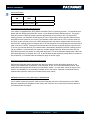
1
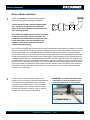
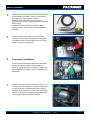
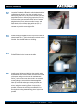
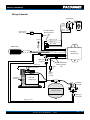
C40078
INLINE MOUNT PRXB™ EXHAUST BRAKES
2007½ - 2008 GM Duramax Diesel - 2500 And 3500 Models
LMM ONLY
NOTE: The C40078 kit is designed for vehicles with factory DPF (Diesel Particulate Filter). This kit is
not recommended or endorsed by Pacbrake for the use in vehicle’s that have had the DPF removed or
bypassed. The Pacbrake system monitors the DPF status, removal or modification of the DPF may have
adverse effects on the Pacbrake operation.
GM Duramax - C40078 LMM Only
Before Starting
Please check the engine and alternator RPO codes to ensure you have the correct exhaust brake kit for the vehicle.
The RPO codes are listed in the glove box of the vehicle, please check them against the chart below before proceeding
with the installation. If your vehicles RPO code is not listed on the chart please contact Pacbrake
factory @ 1-800-663-0096.
Years Mfg
Engine RPO Alternate
Code
RPO Code
Pacbrake Kit Number
Kit Description
2007 1/2 - 2008
LMM
KW1 (single)
C40078
Automatic Transmission without optional 2nd alternator
2007 1/2 - 2008
LMM
K76 (dual)
C40078*
Automatic Transmission with optional 2nd alternator
(found in the
glove box)
*NOTE: K76 Dual Alternator trucks will need to find an alternate compressor mounting location as the optional 2nd alternator uses the Pacbrake compressor mounting location.
LMM/KW1/K76 Designation can be found on RPO code list in glove box
NOTE: The C40078 kit is designed for vehicles with factory DPF (Diesel Particulate Filter). This kit is not recommended or
endorsed by Pacbrake for the use in vehicle’s that have had the DPF removed or bypassed. The Pacbrake system monitors
the DPF status, removal or modification of the DPF may have adverse effects on the Pacbrake operation.
1
Getting Started
Thank you and congratulations on your purchase of a Pacbrake exhaust retarder.
Before starting, check that your kit contains everything shown in the photo below.
C40078 Kit Layout
I N STA L L AT I O N M A N U A L - L5945
Pg. GM Duramax - C40078 LMM Only
Exhaust Brake Installation
2
NOTE: It is manditory to disconnect both negative
battery terminals prior to starting the installation.
CUT HERE
Confirm the vehicle has a factory exhaust header
pipe. The factory header pipe is a double wall
design to retain heat within the exhaust system to
aid in cleaning the DPF.
5.5”
Note: Check the alignment of the header pipe flange
to the turbo outlet pipe, adjust if necessary. The
connection must be leak free and aligned correctly
before the exhaust is cut and the adaptors are
welded in. Leaks at this connection will affect
exhaust brake performance.
A 5.5” section of exhaust pipe will need to be removed to facilitate the exhaust brake and adaptors. A straight
section of exhaust pipe is available in front of the catalytic converter to install the Pacbrake, mark the pipe as
shown in the drawing. This is the ONLY location the exhaust brake may be installed. The section between
the two marks needs to be removed to accommodate the exhaust brake. The exhaust adaptors provided are
designed to fit between the inner and the outer exhaust pipes. Install the adaptors on the exhaust pipes and
install the Pacbrake with the V clamps provided. Be careful to maintain the proper length, any angle that may
exist and sufficient clearance around the exhaust brake. Position the regulator spring and air cylinder behind
the frame rail so it is protected from debris. Tack weld the adaptors to the exhaust system, then remove both
ends of the exhaust for final welding. Both Pacbrake exhaust adaptors need to be welded on the inside and
the outside to maintain the dead air space between the inner and outer exhaust pipes. Clean both gasket
surfaces of the 4 bolt flange.
3
Loosely install the exhaust system using the new
gasket for the 4 bolt flange provided and exhaust brake.
It is important to torque the header pipe to the turbo
outlet pipe first to 10lbs-ft (13N °m). Then torque the
Pacbrake pressure side V clamp to 10lbs-ft (13N °m),
then the rear Pacbrake V clamp to 10lbs-ft (13N °m)
and then the nuts securing the 4 bolt flange.
IMPORTANT: The exhaust brake provided
is directional, it must be installed according to the exhaust flow as shown below:
Muffler Side
Turbo Side
<<< EXHAUST FLOW <<<
I N STA L L AT I O N M A N U A L - L5945
Pg. GM Duramax - C40078 LMM Only
4
Install the remote breather hose onto the barbed fitting
of the Pacbrake air cylinder. Secure it to the barbed
fitting with one of the tie-straps provided.
Route the other end of the hose to the engine
compartment, it will be connected to the air compressor
filter in step 9.
Install the 90° fitting into the air cylinder pointing it
towards the front of the vehicle, use thread sealant on
the fitting.
5
At the front driver’s side battery open the box and
connect the red wire with 30 amp fuse to the terminal
of the battery stud. Use the supplied nut, lock and flat
washer on top of the existing nut.
6
Compressor Installation
Loosely install the two metric capscrews and washers
supplied through the bracket, loosely install the
capscrew, lock & flat washer throught the compressor
support bracket to the factory rivnut, located below the
compressor.
7
Tighten all the capscrews evenly including the ¼” nut
and bolt under the compressor. Connect the metri-pac
connector with the red and blue wires to the mating
connector of the compressor. Route these wires along
with the red wire from the battery, through the fire wall,
to be connected to the controller in step 16.
I N STA L L AT I O N M A N U A L - L5945
Pg. GM Duramax - C40078 LMM Only
8
Install the 14’ nylon air line supplied into the
compression fitting at the compressor, route it with the
solenoid wiring (purple and black harness with metripac connector) to the passengers side of the frame. (air
tank location - installed in step 13).
9
Locate the air cylinder breather hose in the engine
compartment installed in step 4. This hose connects
to the air compressor inlet filter with the “T” fitting
provided. Connect the filter, the air compressor intake
and the cylinder breather hose as shown. The filter
housing is installed into the hole below the radiator in
the support bracket. Mounting the air intake filter infront
of the radiator will ensure the coolest air possible is
supplied to the compressor
10
1/4’’
nylon line
provided
Installing The Pacbrake Harness
Locate the diagnostic connector under the dash on the
drivers side. Connect the male plug of the Pacbrake
harness, containing the twisted green and yellow wire
pair, to the factory diagnostic connector. Secure the two
connectors with a tie-strap.
11
Secure the Pacbrake control unit to the firewall. Locate
the two holes in the firewall bracket shown in the photo,
thread a tie-strap through the two holes to secure the
control unit to the firewall. Secure the wires with the tiestraps provided.
I N STA L L AT I O N M A N U A L - L5945
Pg. GM Duramax - C40078 LMM Only
12
Locate the Pacbrake LED switch with the twisted white/
red/black/purple wiring. Crimp the red switch wire to
harness plug red wire (Pin 22) of the controller harness,
purple switch wire to harness plug purple wire (Pin 14)
of the controller harness, black switch wire to harness
plug black wire (Pin 2) of the controller harness, and
white switch wire to harness plug white wire (Pin 1)
of the controller harness. Once crimped, heat the
connector to provide a water tight seal.
13
Install the fittings supplied into the top of the air tank as
shown. Install the ¼” plug in the bottom or a drain valve
if desired. Use thread sealant on all fittings.
14
Drill two 5/16" holes in the frame on 3 ¼” centers to
mount the tank on the outside of the frame.
15
Install the two fittings provided into the solenoid using
thread sealant.The solenoid valve mounts on the inside
of the frame using one of the two air tank fasteners.
Drill a ¼” hole to secure the other hole in the solenoid
mounting flange, secure with the fastener supplied.
Note: the solenoid exhaust port must point down as
shown.Connect the solenoid port marked IN to the
air tank using the remaining piece of nylon air line
provided. Connect the solenoid port marked CYL to
the air cylinder using the remaining piece of nylon line
provided.
I N STA L L AT I O N M A N U A L - L5945
Pg. GM Duramax - C40078 LMM Only
15
Connect the metri-pac connector of the solenoid, to
Cont... the mating connector with orange and black 20 AWG
wires of the Pacbrake harness. Route these wires along
the frame to the driver side firewall and then into the
cab. Secure the wiring harness and nylon air line away
from heat sources and moving items with the tie-straps
provided.
16
Connect either one of the two 14 AWG red wires
originating at the small plug of the Pacbrake controller
to the 30 amp fused 14 AWG red wire. Connect the
14 AWG red wire originating at the compressor to the
remaining 14 AWG red wire of the small plug of the
controller. Connect the remaining 14 AGW to the red
wire from the compressor. Connect the three 20 AWG
wires to the corresponding colored wires at the grey
connector of the controller, blue (to pin 18), black (to pin
23) and orange (to pin13).
17
Route the 67” long red 20 AWG wire, (connected to Pin
21 in the grey harness plug), through the firewall to the
main fuse box of the vehicle. Crimp the 20 AWG red
wire to the wire attached to the fuse tap. The 3 amp
fuse is inserted into the top slot of the fuse tap. Remove
the lid of the fuse box by pushing in the plastic tabs that
are located on the side facing the engine. Locate the 15
amp fuse in location 53 (ECM-IGN). This 15 amp fuse
is then removed and inserted into the fuse tap below
the 3 amp fuse supplied in the Pacbrake kit.
Once crimped, heat the connector to provide a water
tight seal.
Insert the fuse tap into the fuse panel where the 15 amp
fuse was removed Re-install the fuse cover.
Originally Looks
Looks
Originally
Like This:
This:
Like
Pacbrake supplied
fuse
Pacbrake
Power Supply
Existing fuse from
Location 53
Insert Here:
Here:
Insert
I N STA L L AT I O N M A N U A L - L5945
Pg. GM Duramax - C40078 LMM Only
18
Pacbrake control switch location can vary depending
on customer preference and the availablity of space. A
suggested location is on the left hand side of the dash
panel.
19
Connect the battery terminals disconnected in step 2.
Check Operation
With the Pacbrake switch in the OFF position, start the engine and allow to idle. The Pacbrake compressor
should pump air for approx. 2 minutes (this will fill the air tank from empty). Once the Pacbrake control unit
confirms the air tank has reached maximum pressure the control unit will perform a “Self Test Cycle” which
activates the exhaust brake 3 times with the vehicle stationary. After the “Self Test Cycle” is complete the
exhaust brake will not activate with the vehicle stationary even with the exhaust brake switch in the ON
position.
LED Switch Operation
With the vehicle’s ignition ON, and the switch in the ON position, the switch will turn red then momentary
green illumination for initialization. The LED switch will then change back to a constant red illumination.
LED Switch Operation
• RED - Brake enabled and ready for activation
• ORANGE - Brake currently active
• GREEN - Diesel Particulate Filter (DPF) Regeneration is active, and the exhaust brake is disabled
until DPF Regeneration is complete
• NO ILLUMINATION - Brake disabled/OFF
Road testing with an Allison 1000 series transmission
Test drive the vehicle with the Tow/Haul switched ON and the Pacbrake switch ON. Tow/Haul mode must
be engaged when using the exhaust brake. Activating the Pacbrake several times will send a message to
the Allison ECU to engage lock up and downshift the transmission to enhance exhaust braking. The first few
times the exhaust brake activates it may not be very impressive but once the Allison ECU learns an exhaust
brake is being activated, the ECU will apply lockup quicker and generate greater retarding. Downshifting will
occur when the exhaust brake is activated as this is a normal feature of the Allison transmission. Customers
may experience a very strong 2nd to 1st gear downshift. Over time the Allison ECU will compensate for it.
The exhaust brake will turn off below 15 to 18 MPH or 25 to 30 km/h.
I N STA L L AT I O N M A N U A L - L5945
Pg. GM Duramax - C40078 LMM Only
19
Cont...
Functional Parameter:
Brake Will Turn Brake Will Turn
ON
OFF
Tow/Haul State
22 MPH (35 KMH)
19 MPH (30 KMH)
ON
50 MPH (80 KMH)
47 MPH (75 KMH)
OFF
Important Information Regarding DPF Regeneration
Your vehicle is equipped with a (DPF) Diesel Particulate Filter for emissions purposes. You should become
familiar with the “Diesel Particulate Filter” section of your Duramax Diesel LMM user manual. The engine
ECU will command a DPF self cleaning process approximately once per tank of fuel. During the DPF
cleaning process, your Pacbrake will not operate in order to ensure that it doesn’t interfere with the factory
designed emission system on your vehicle. The Pacbrake enable switch has an L.E.D. indicator which will
turn green to alert you that you are in the DPF cleaning process and that the exhaust brake will not function.
Once the DPF cleaning process is complete the L.E.D. will change back to red indicating the exhaust brake is
ready to function. The DPF cleaning process will take about 20 minutes at speeds above 30 mph (50 km/h).
To ensure you minimize the time your exhaust brake is automatically disabled by the DPF cleaning process,
if at all possible it is recommended you travel at a constant highway speed for about 20 minutes once the
DPF cleaning process has started, as notified with the green L.E.D. in the Pacbrake enable switch. When the
DPF cleaning process is complete, the L.E.D. on the Pacbrake enable switch will change back to red when in
the ON position, your exhaust brake will seamlessly begin to function again.
Important Information Regarding Other Aftermarket Products:
Unfortunately Pacbrake cannot guarantee that, with the multitude of other aftermarket products on the
market, your Pacbrake will not influence, or be influenced, by the use of other aftermarket products, most
notibly those that interface with the truck’s communication system. In some cases, due to the nature of the
devices, incompatibility is not reasonably avoidable, and for this reason, Pacbrake recommends that this
exhaust brake system be used on an otherwise factory stock vehicle
IMPORTANT NOTE: Disconnecting OBD II Plug for SERVICE WORK
If your vehicle requires service work, make sure the Pacbrake connector is disconnected from the OBD II
plug from underneath the dashboard on the driver’s side. Failure to do so could result in adverse effects to
your exhaust brake and engine.
I N STA L L AT I O N M A N U A L - L5945
Pg. GM Duramax - C40078 LMM Only
Wiring Schematic
Dash Switch
White
Purple
Heat Shrinkable
Butt Connector
(x5)
Fuse
Black
Pin 24
Ground
OBD II Plug
8
1
White - Pin 1
Red - Pin 22
Black - Pin 2
Pin 6 - Yellow
Pin 14 - Green
16
OFF
Red
Purple - Pin 14
Red - Pin 21
Ignition Power
At Fuse Panel
Black
Pin 12 - Yellow
Pin 11 - Green
9
Pacbrake
Control Unit
Red
Metri-pac
connector
Blue Pin 18
B
Pressure Switch
A
Heat Shrinkable
Butt Connector
(x5)
30 amp
fuse
Positive
battery
terminal
Compressor
Air Intake
Pacbrake
Compressor
Black
C
Y
L
Pacbrake
Solenoid
Pacbrake Air Tank
Metri-pac
connector
Orange - Pin 13
Black - Pin 23
I N STA L L AT I O N M A N U A L - L5945
Pg. 10