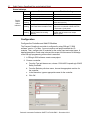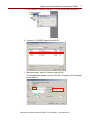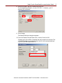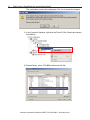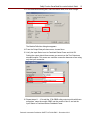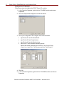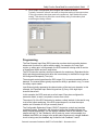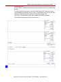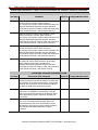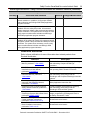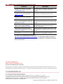
1
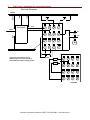
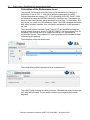
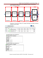
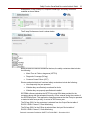
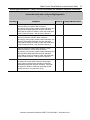
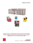
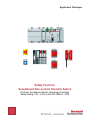
Application Technique
Safety Function:
SensaGuard Non-contact Interlock Switch
Products: SensaGuard Switch, GuardLogix Controller
Safety Rating: CAT. 4, PLe to EN ISO 13849-1: 2008
2
Safety Function: SensaGuard Non-contact Interlock Switch
Important User Information
Read this document and the documents listed in the additional resources section about installation,
configuration, and operation of this equipment before you install, configure, operate, or maintain this
product. Users are required to familiarize themselves with installation and wiring instructions in addition
to requirements of all applicable codes, laws, and standards.
Activities including installation, adjustments, putting into service, use, assembly, disassembly, and
maintenance are required to be carried out by suitably trained personnel in accordance with applicable
code of practice.
If this equipment is used in a manner not specified by the manufacturer, the protection provided by the
equipment may be impaired.
In no event will Rockwell Automation, Inc. be responsible or liable for indirect or consequential
damages resulting from the use or application of this equipment.
The examples and diagrams in this manual are included solely for illustrative purposes. Because of the
many variables and requirements associated with any particular installation, Rockwell Automation, Inc.
cannot assume responsibility or liability for actual use based on the examples and diagrams.
No patent liability is assumed by Rockwell Automation, Inc. with respect to use of information, circuits,
equipment, or software described in this manual.
Reproduction of the contents of this manual, in whole or in part, without written permission of Rockwell
Automation, Inc., is prohibited.
Throughout this manual, when necessary, we use notes to make you aware of safety considerations.
WARNING: Identifies information about practices or circumstances that can
cause an explosion in a hazardous environment, which may lead to personal
injury or death, property damage, or economic loss.
ATTENTION: Identifies information about practices or circumstances that can
lead to personal injury or death, property damage, or economic loss. Attentions
help you identify a hazard, avoid a hazard, and recognize the consequence.
IMPORTANT
Identifies information that is critical for successful application and
understanding of the product.
Labels may also be on or inside the equipment to provide specific precautions.
SHOCK HAZARD: Labels may be on or inside the equipment, for example, a
drive or motor, to alert people that dangerous voltage may be present.
BURN HAZARD: Labels may be on or inside the equipment, for example, a
drive or motor, to alert people that surfaces may reach dangerous
temperatures.
ARC FLASH HAZARD: Labels may be on or inside the equipment, for
example, a motor control center, to alert people to potential Arc Flash. Arc
Flash will cause severe injury or death. Wear proper Personal Protective
Equipment (PPE). Follow ALL Regulatory requirements for safe work practices
and for Personal Protective Equipment (PPE).
Rockwell Automation Publication SAFETY-AT108A-EN-P – December 2013
Safety Function: SensaGuard Non-contact Interlock Switch
3
General Safety Information
Contact Rockwell Automation to find out more about our safety risk assessment
services.
IMPORTANT
This application example is for advanced users and
assumes that you are trained and experienced in safety
system requirements.
ATTENTION: Perform a risk assessment to make sure all
task and hazard combinations have been identified and
addressed. The risk assessment can require additional
circuitry to reduce the risk to a tolerable level. Safety circuits
must take into consideration safety distance calculations,
which are not part of the scope of this document.
Table of Contents
Important User Information ....................................................................................... 2
General Safety Information ....................................................................................... 3
Introduction ............................................................................................................... 3
Safety Function Realization: Risk Assessment ......................................................... 4
SensaGuard Switch Safety Function ......................................................................... 4
Safety Function Requirements .................................................................................. 4
Functional Safety Description ................................................................................... 5
Bill of Material ........................................................................................................... 5
Setup and Wiring ...................................................................................................... 6
Configuration .......................................................................................................... 10
Programming .......................................................................................................... 17
Calculation of the Performance Level...................................................................... 20
Verification and Validation Plan............................................................................... 24
Additional Resources .............................................................................................. 29
Introduction
This safety function application technique explains how to wire, configure, and
program a Compact GuardLogix® controller and POINT Guard I/O™ module to
monitor both an E-stop button and a SensaGuard™ switch. When the moveable door
is opened, the E-stop button is actuated, or a fault is detected in the monitoring
circuit, the safety controller de-energizes the final control devices, in this case, a
redundant pair of 100S contactors.
This example uses a Compact GuardLogix controller, but is applicable to any
GuardLogix controller. This example uses a SensaGuard switch and an E-stop
button. The SISTEMA software PL calculation tool calculations shown later in this
document must be re-calculated if different products are used.
Rockwell Automation Publication SAFETY-AT108A-EN-P – December 2013
4
Safety Function: SensaGuard Non-contact Interlock Switch
Safety Function Realization: Risk Assessment
The required performance level (PLr) is the result of a risk assessment and refers to
the amount of the risk reduction to be carried out by the safety-related parts of the
control system. Part of the risk reduction process is to determine the safety functions
of the machine. In this application, the PLr by the risk assessment is Category 3,
Performance Level d (CAT. 3, PLd), for each safety function. A safety system that
achieves CAT. 3, PLd, or higher, can be considered control reliable. Each safety
product has its own rating and can be combined to create a safety function that
meets or exceeds the PLr.
From: Risk Assessment (ISO 12100)
1. Identification of safety functions
2. Specification of characteristics of each function
3. Determination of required PL (PLr) for each safety function
To: Realization and PL Evaluation
SensaGuard Switch Safety Function
The safety system described in this application has two safety functions.
•
Safety-related stop function initiated by the SensaGuard switch
•
Emergency stop initiated by actuation of an E-stop button
This system executes a Stop Category 0 stop. Power is removed and motion coasts
to a stop.
Safety Function Requirements
When the moveable door is opened for access, the SensaGuard switch sends
signals to the safety controller to de-energize outputs, stopping the hazardous
motion by removing power to the motor. The system cannot be reset while the
moveable door is open. Once the door is closed, and the Reset button is pressed
and released (a separate action), the electrical circuit is re-established and the
machine is ready to start.
Pressing the E-stop button stops the hazardous motion by removing power to the
motor by the use of two safety contactors. Releasing the E-stop button does not
restart the hazardous motion. Pressing and releasing the Reset button after the
E-stop button has been reset and all faults are cleared, prepares the machine for
Rockwell Automation Publication SAFETY-AT108A-EN-P – December 2013
Safety Function: SensaGuard Non-contact Interlock Switch
5
normal operation (ready to run). The machine runs after the Start button is pressed.
A fault at the SensaGuard switch, E-stop, wiring terminals, or safety controller is
detected before the next safety demand.
The safety system described in this application technique is capable of connecting
and interrupting power to motors rated up to 9 A, 600V AC. The safety functions in
this application technique each meet or exceed the requirements for Category 3,
Performance Level d (CAT. 3, PLd), per EN ISO 13849-1 and control reliable
operation per ANSI B11.19.
Functional Safety Description
The SensaGuard switch and the E-stop button are wired to pairs of safety inputs of a
safety input module (SI1). The safety contactors (K1 and K2) are connected to a pair
of safety outputs of a safety output module (SO1). The I/O module is connected, via
CIP Safety, over an EtherNet/IP network to the safety controller (SC1). The safety
code in SC1 monitors the status of the SensaGuard switch and E-stop button by
using the pre-certified safety instruction Dual Channel Input Stop (DCS). When all
safety input interlocks are satisfied, no faults are detected, and the Reset button is
pressed and released, a second pre-certified function block called Configurable
Redundant Output (CROUT) controls and monitors feedback for a pair of 100S
redundant contactors.
Bill of Material
This application uses these products.
Cat. No.
440N-Z21SS2HN
Description
1
SensaGuard, plastic rectangular, 2 x PNP, 0.2 A, max.,
safety output, 6 in. pigtail, 8-pin micro (M12), margin
indication
889D-F8AB-2
DC micro (M12), female, straight, 8-pin, PVC cable,
yellow, unshielded, 24AWG, 2 m
800FM-G611MX10 800F push button - metal, guarded, blue, R, metal latch
mount, 1 N.O. contact, standard
800FP-MT44PX02S 800F non-illuminated mushroom operators,
twist-to-release, 40 mm, round, plastic, red, plastic latch
mount, 0 N.O. contacts, 2 N.C. contacts, self-monitoring
800F-1YP3
800F 1-hole enclosure E-stop station, plastic, PG
twist-to-release 40 mm, non-illuminated, 2 N.C. contacts
100S-C09EJ23C
Bulletin 100S-C - safety contactors, 9 A, 24V DC
1768-ENBT
CompactLogix™ EtherNet/IP bridge module
1768-L43S
Compact GuardLogix processor, 2.0 Mb standard
memory, 0.5 Mb safety memory
1768-PA3
Power supply, 120/240V AC input, 3.5 A@ 24V DC
1769-ECR
Right end cap/terminator
1734-AENT
24V DC Ethernet adapter
1734-TB
Module base with removable IEC screw terminals
1734-IB8S
POINT Guard I/O safety input module
1734-OB8S
POINT Guard I/O safety output module
1783-US05T
Stratix 2000™ unmanaged Ethernet switch
1
Any 440N-Z SensaGuard product can be used in this application.
Rockwell Automation Publication SAFETY-AT108A-EN-P – December 2013
Quantity
1
1
1
1
1
2
1
1
1
1
1
4
1
1
1
6
Safety Function: SensaGuard Non-contact Interlock Switch
Setup and Wiring
For detailed information on installing and wiring, refer to the product manuals listed in
the Additional Resources.
System Overview
The 1734-IB8S input module monitors two output signal switching devices (OSSD)
from the SensaGuard switch. If the moveable door is opened, the SensaGuard
switch turns off its two PNP outputs (OSSD Safety A and OSSD Safety B) and the
safety controller reacts by turning off the two safety outputs. This removes 24V DC
from the coils of the two safety contactors whose contacts open, removing power to
the motor. The motor coasts to a stop (Stop Category 0).
The SensaGuard switch OSSD outputs (Safety A and Safety B) turn on once the
door is closed. The SensaGuard switch monitors its internal circuitry and its OSSD
outputs for faults. When a fault in the internal circuitry or an output is detected, the
SensaGuard switch responds by turning off its OSSD outputs.
The pulse-test outputs (T0 and T1) wired to the 1734-IB8S input module are run
through the two N.C. contacts of the E-stop to inputs I2 and I3, respectively. When
the E-stop is pressed and released, these circuits are interrupted. The safety
controller reacts by turning the safety contacts off. This removes power from the
100S contactor coils and removing 24V DC from the coils of the two 100S
contactors, whose contacts open, removing power to the motor. The motor coasts to
a stop (Stop Category 0).
Shorts to 0V DC (and wire off) are seen as an open circuit by the 1734-IB8S input
module and the safety controller reacts by dropping out the safety contactors. If the
inputs remain discrepant for longer than the discrepancy time, then the function block
Dual Channel Input Stop (DCS) in the safety controller declares a fault. Only after the
fault is cleared and the SensaGuard switch or E-stop inputs are cycled (door opened,
then closed or push and release the button), is the function block reset.
The final control devices are a pair of 100S safety contactors, K1 and K2.The
contactors are controlled by a 1734-OB8S safety output module. The contactors are
wired in a redundant series configuration. A feedback circuit is wired through the
N.C. contacts and back to an input on the 1734-IB8S, to monitor the contactors for
proper operation. The contactors cannot restart if the feedback circuit is not in the
correct state.
The system has individual Reset buttons for resetting faults and safety outputs. The
Reset buttons and the two contactor feedbacks circuit are all wired to the 1734-IB8S
module in this example. This is not required for functional safety. These three inputs
can be wired to a standard input module.
Rockwell Automation Publication SAFETY-AT108A-EN-P – December 2013
Safety Function: SensaGuard Non-contact Interlock Switch
7
Installation
Refer to the installation instruction and user manuals for guidance on installing and
maintaining the different parts of this system.
The size of the openings must prevent the operator from reaching the hazard. Table
O-10 in U.S. OHSA 1910.217 (f) (4), EN ISO 13854, Table D-1 of ANSI B11.19,
Table 3 in CSA Z432, and AS4024.1, provide guidance on the appropriate distance a
specific opening must be from the hazard.
Hazard Area
Stop
Switch
Actuator
Sliding Guard
Guard Open – Machine Stopped – Guard Covering Switch
RFID Non-Contact Interlock Switches
Non-contact interlock switches based on Radio Frequency Identification (RFID)
technology can provide a very high level of security against defeat by simple tools.
This technology can also be used to provide devices with unique coding for
applications where security is paramount.
The use of RFID technology has many other important advantages. RFID technology
is suitable for use with high-integrity circuit architectures, such as Category 4,
Performance Level e, or SIL 3. RFID technology can be incorporated into devices
with fully-sealed IP69K enclosures manufactured from plastic or stainless steel.
When RFID technology is used for coding, and inductive technology for sensing, a
large sensing range and tolerance to misalignment can be achieved, typically
15…25 mm. This means that these devices can provide very stable and reliable
service combined with high levels of integrity and security over a wide range of
industrial safety applications. The SensaGuard switch interlocks use RFID
technology.
Rockwell Automation Publication SAFETY-AT108A-EN-P – December 2013
8
Safety Function: SensaGuard Non-contact Interlock Switch
Electrical Schematic
SensaGuard*
Pink
Gray
K1
K2
Blue
White
Aux. Contact
Fault Reset
Safety Reset
Yellow
Red
Brown
24V DC
M
1734-IB8S
24V DC COMMON
* Stainless steel models have an
additional green wire that should be
terminated to the power supply ground.
E-stop
K1
K2
1734-OB8S
Rockwell Automation Publication SAFETY-AT108A-EN-P – December 2013
Safety Function: SensaGuard Non-contact Interlock Switch
9
Typical Wiring Diagrams
Description
Plastic
Stainless Steel
3-Shield
8-Safety A+
4-Safety B+
8-pin Micro (M12)
8-Safety A+
4-Safety B+
7-Ground
6-Safety B
5-Safety A
7-Ground
6-Safety B
5-Safety A
8-pin Cordset
1
889D-F8ABor cable
version
Gray
Safety A
Safety A
Red
Safety A+
Safety A+
Pink
Safety B
Safety B
Yellow
Safety B+
Safety B+
White
Aux A
Aux A
Brown
24V DC+
24V DC+
Blue
Gnd
Gnd
2
Green
NA
Shield
1
Replace symbol with 2 (2 m), 5 (5 m), or 10 (10 m) for standard cable lengths.
2
Green wire only applies to the stainless steel model.
24V DC
Power
Supply
Actuator 1
1606
-XL120D
Switch 1
Actuator 4
Actuator 5
Switch 2
Switch 3
Switch 4
Switch 5
Pink
Actuator 4 is in sensing range
Switch 4 is functioning properly
Series inputs are 0V DC
OSSDs are de-energized to 0V DC
Green status indicator is flashing to
indicate series inputs are not 24V
DC
Gray
Brown
Red
Yellow
Pink
Gray
Brown
Actuator 3 is in sensing range
Switch 3 has fault
See table below – Red status
indicator is flashing
Red
Yellow
Gray
Pink
Actuator 2 is in sensing range
Switch 2 is functioning properly
OSSDs are energized to 24V DC
Green status indicator is ON
Brown
Red
Yellow
Pink
Gray
Brown
Actuator 1 is in sensing range
Switch 1 is functioning properly
OSSDs are energized to 24V DC
Green status indicator is ON
Actuator 3
Red
Yellow
Pink
Gray
Brown
Red
White
Yellow
Recoverable
Fault
Actuator 2
Actuator 5 is in sensing range.
Switch 5 is functioning properly
Series inputs are 0V DC
OSSDs are de-energized to
0V DC
Green status indicator is flashing
to indicate series inputs are not
24V DC
18 mm Actuator
Rockwell Automation Publication SAFETY-AT108A-EN-P – December 2013
OSSDs
are
Off
10
Safety Function: SensaGuard Non-contact Interlock Switch
Status Indicators
State
Device
Output
Status
Indicator
Off
Red
Green
Green
Flashing
Red
Flashing
Status
Not Powered
Not Safe, Output Off
Safe, Output On
Power-up Test
1 Hz Flash Recoverable Fault
4 Hz Flash Nonrecoverable Fault
Amber
Safe, output on, sensor is
Flashing reaching maximum sensing
distance
Troubleshooting
NA
NA
NA
Check 24V DC on safety + outputs
(yellow and red wire)
Recoverable Fault: Check that safety
outputs are not shorted to GND, 24V DC,
or each other. Cycle power.
Readjust the distance between the
actuator and the sensor until output
status is green.
Configuration
Configure the Controller and Add I/O Modules
The Compact GuardLogix controller is configured by using RSLogix™ 5000
software, version 17 or later. You must create a new project and add the I/O
modules. Then, configure the I/O modules for the correct input and output types. A
detailed description of each step is beyond the scope of this document. Knowledge
of the RSLogix programming environment is assumed.
1. In RSLogix 5000 software, create a new project.
2. Choose a controller.
a. From the Type pull-down menu, choose 1768-L43S CompactLogix 5343S
Safety Controller.
b. From the Revision pull-down menu, choose the appropriate revision for
the controller.
c. In the Name box, type an appropriate name for the controller.
d. Click OK.
Rockwell Automation Publication SAFETY-AT108A-EN-P – December 2013
Safety Function: SensaGuard Non-contact Interlock Switch
11
3. In the Controller Organizer, right-click 1768 Bus and choose New Module.
4. Choose the 1768-ENBT module and click OK.
5. Name the module, type its IP address, and click OK.
For this application example, we used 192.168.1.8; however, your IP address
can be different.
Rockwell Automation Publication SAFETY-AT108A-EN-P – December 2013
12
Safety Function: SensaGuard Non-contact Interlock Switch
6. In the Controller Organizer, right-click the Ethernet network and choose New
Module.
7. Select the 1734-AENT adapter and click OK.
Rockwell Automation Publication SAFETY-AT108A-EN-P – December 2013
Safety Function: SensaGuard Non-contact Interlock Switch
8. Name the module, type its IP address and click OK.
For this application example, we used 192.168.1.11; however, your IP
address can be different.
9. Click Change.
The Module Definition dialog box appears.
10. From the Chassis Size pull-down menu, choose 3 and click OK.
Chassis size is the number of modules that are inserted in the chassis. The
1734-AENT adapter is considered to be in slot 0, so for one input and one
output module, the chassis size is 3.
Rockwell Automation Publication SAFETY-AT108A-EN-P – December 2013
13
14
Safety Function: SensaGuard Non-contact Interlock Switch
The confirmation screen will be displayed. Click Yes to accept the changes.
11. In the Controller Organizer, right-click the PointIO 3 Slot Chassis and choose
New Module.
12. Expand Safety, select 1734-IB8S module and click OK.
Rockwell Automation Publication SAFETY-AT108A-EN-P – December 2013
Safety Function: SensaGuard Non-contact Interlock Switch
15
13. In the New Module dialog box, name the device IB8S, then click Change.
The Module Definition dialog box appears.
14. From the Output Data pull-down menu, choose None.
15. Verify the Input Status is set to Combined Status-Power and click OK.
Setting the output data to None means you cannot use the Test Outputs as
standard outputs. This saves one controller connection because we are using
only the input connection.
16. Repeat steps 11…15 to add the 1734-OB8S safety output module with these
exceptions, name the module OB8S, set the module to slot 2, and set the
Input Status to Combined Status-Feedback-Power.
.
Rockwell Automation Publication SAFETY-AT108A-EN-P – December 2013
16
Safety Function: SensaGuard Non-contact Interlock Switch
Configure the I/O Modules
Follow these steps to configure the POINT Guard I/O modules.
1. In the Controller Organizer, right-click the 1734-IB8S module and choose
Properties.
2. Click Test Output and configure the module as shown.
3. Click Input Configuration and configure the module as shown:
•
Input Points 0/1 are the SensaGuard.
•
Input Points 2/3 are E-stop buttons.
•
Input Points 4/5 are the Reset buttons.
•
Input Point 7 is the contactor monitoring circuit.
Inputs Point 2 and 3 are being sourced from Test Output 0 and 1,
respectively. Input Point 7 is being sourced from Test Output 2.
4. Click OK.
5. In the Controller Organizer, right-click the 1734-OB8S module and choose
Properties.
Rockwell Automation Publication SAFETY-AT108A-EN-P – December 2013
Safety Function: SensaGuard Non-contact Interlock Switch
17
6. Click Output Configuration and configure the module as shown.
Typically, contactor coils will not react to the pulse testing of the output wires.
If using a contactor that does react to the pulse test, then disable the pulse
testing. This should not affect the overall safety rating if redundancy and
monitoring are being utilized.
7. Click OK.
Programming
The Dual Channel Input Stop (DCS) instruction monitors dual-input safety devices
whose main function is to stop a machine safely, for example, an E-stop, light
curtain, or safety gate. In this example, the DCS instruction is being used to monitor
a SensaGuard switch and an E-stop button.
The DCS instruction monitors dual-input channels for consistency (Equivalent-Active
High) and detects and traps faults when the inconsistency is detected for longer than
the configured Discrepancy Time (ms).
The automatic restart type allows the DCS output (O1) to reset automatically after a
demand. The manual action typically required for safety is provided in rung 1 to reset
the safety output enable.
Input Status typically represents the channel status of the two input channels. In this
example, the Combined Input Status bit goes low (0) if any of the eight input
channels has a fault.
In this example, the DCS reset acts as a fault reset. Even when configured for
automatic restart, a reset is required to recover from a fault.
The output (01) of the DCS instruction is used as a safety interlock in the seal-in rung
to drive the output enable tag. If the DCS output drops out, so does the output
enable, and it remains off until you manually reset it.
The Configurable Redundant Output (CROUT) instruction controls and monitors
redundant outputs. Essentially, this instruction verifies that feedback follows the
safety outputs appropriately. For the negative feedback used in this example, if the
outputs are high (1), the Feedback is low (0) and vice versa. In this example, the
feedback has 500 ms to change to the proper state. Because only a single feedback
circuit is being used, the feedback tag is used for both Feedback 1 and 2.
Rockwell Automation Publication SAFETY-AT108A-EN-P – December 2013
18
Safety Function: SensaGuard Non-contact Interlock Switch
The two output tags from the CROUT instruction are used to drive the contactor
outputs on the 1734-OB8S module.
Rockwell Automation Publication SAFETY-AT108A-EN-P – December 2013
Safety Function: SensaGuard Non-contact Interlock Switch
19
Falling Edge Reset
EN ISO 13849-1 stipulates that instruction reset functions must occur on falling edge
signals.
To comply with this requirement, add a One Shot Falling (OSF) instruction to the
rung immediately preceding the Cmd_Zone1_OutputEnable rung, then use the OSF
instruction Output Bit tag as the reset bit for the following rung. The
Cmd_Zone1_OutputEnable is still used to enable the CROUT instruction.
The modified code appears below in rungs 1 and 2.
Rockwell Automation Publication SAFETY-AT108A-EN-P – December 2013
20
Safety Function: SensaGuard Non-contact Interlock Switch
Calculation of the Performance Level
The required Performance Level (PLr) from the risk assessment is Category 3,
Performance Level d (CAT. 3, PLd). When properly implemented, the safety
functions described can achieve CAT. 4, PLe, according to EN ISO 13849-1: 2008,
as calculated by using the SISTEMA software PL calculation tool. Calculations are
based on each safety function being operated 5 times an hour, 12 hours a day, 365
days a year, for a total of 21,900 operations a year. The 100S contactors are used in
both safety functions; therefore, their calculations are based on 43,800 operations
per year.
The measures against Common Cause Failure (CCF) are quantified by using the
scoring process outlined in Annex F of EN ISO 13849-1. For the purposes of the PL
calculation, the required score of 65 needed to fulfill the CCF requirement is
considered to be met. The complete CCF scoring process must be performed when
implementing this example.
The subsystem values are shown below.
The overall safety project Performance Level is shown below.
This safety System includes two safety functions, a SensaGuard safety function and
an E-stop safety function. The two safety functions can be represented in block
diagrams.
Rockwell Automation Publication SAFETY-AT108A-EN-P – December 2013
Safety Function: SensaGuard Non-contact Interlock Switch
21
The SensaGuard safety function can be modeled as shown in the following
safety-related block diagram.
K1
100S
SensaGuard
1734-IB8S
1768-L43S
1734-OB8S
K2
100S
Subsystem 1
Subsystem 2
Subsystem 3
Subsystem 4
Subsystem 5
Subsystems: SensaGuard, Safety I/O, Compact GuardLogix, and safety contactors
modeled as shown below.
SensaGuard Safety Function Subsystem 1
SensaGuard Safety Function Subsystem 2
Rockwell Automation Publication SAFETY-AT108A-EN-P – December 2013
22
Safety Function: SensaGuard Non-contact Interlock Switch
SensaGuard Safety Function Subsystem 3
SensaGuard Safety Function Subsystem 4
SensaGuard Safety Function Subsystem 5
The E-Stop safety function is represented below.
E-stop 1
B1/E1
K1
100S
1734-IB8S
1768-L43S
1734-OB8S
Estop 1
B2/E2
K2
100S
Subsystem 1
Subsystem 2
Subsystem 3
Subsystem 4
Subsystem 5
Rockwell Automation Publication SAFETY-AT108A-EN-P – December 2013
Safety Function: SensaGuard Non-contact Interlock Switch
23
Subsystems: E-stop, Safety I/O, Compact GuardLogix, and safety contactors
modeled as shown below.
The E-stop Performance Level is shown below.
Because these are electro-mechanical devices, the safety contactors data includes
the following:
•
Mean Time to Failure, dangerous (MTTFd)
•
Diagnostic Coverage (DCavg)
•
Common Cause Failure (CCF)
Electro-mechanical devices’ functional safety evaluations include the following:
•
How frequently they are operated
•
Whether they are effectively monitored for faults
•
Whether they are properly specified and installed
SISTEMA software calculates the MTTFd by using B10d data provided for the
contactors along with the estimated frequency of use, entered during the creation of
the SISTEMA project. This application example presumes that the E-stop is operated
or tested at least once per day, for a total of 365 times a year.
The DCavg (99%) for the contactors is selected from the Output Device table of
EN ISO 13849-1 Annex E, Direct Monitoring.
The DCavg (99%) for the E-Stop is selected from the Input Device table of
EN ISO 13849-1 Annex E, Cross Monitoring.
Rockwell Automation Publication SAFETY-AT108A-EN-P – December 2013
24
Safety Function: SensaGuard Non-contact Interlock Switch
Verification and Validation Plan
Verification and validation play important roles in the avoidance of faults throughout
the safety system design and development process. EN ISO 13849-2 sets the
requirements for verification and validation. The standard calls for a documented
plan to confirm all of the safety functional requirements have been met.
Verification is an analysis of the resulting safety control system. The Performance
Level (PL) of the safety control system is calculated to confirm that the system meets
the required Performance Level (PLr) specified. The SISTEMA software is typically
used to perform the calculations and assist with satisfying the requirements of
EN ISO 13849-1.
Validation is a functional test of the safety control system to demonstrate that the
system meets the specified requirements of the safety function. The safety control
system is tested to confirm that all of the safety-related outputs respond
appropriately to their corresponding safety-related inputs. The functional test
includes normal operating conditions in addition to potential fault injection of failure
modes. A checklist is typically used to document the validation of the safety control
system.
Validation of software development is the process in which similar methodologies
and techniques that are used in hardware development are deployed. Faults created
through poor software development processes and procedures are systemic in
nature rather than faults associated with hardware, which are considered as random.
Prior to validating the GuardLogix Safety System, it is necessary to confirm that the
safety system and safety application program have been designed in accordance
with the GuardLogix System Safety Reference Manuals, publication 1756-RM093
(GuardLogix 5560 and Compact GuardLogix controllers) and 1756-RM099
(GuardLogix 5570 controllers), and the GuardLogix Application Instruction Safety
Reference Manual, publication 1756-RM095.
Rockwell Automation Publication SAFETY-AT108A-EN-P – December 2013
Safety Function: SensaGuard Non-contact Interlock Switch
25
GuardLogix/SensaGuard - Safety Function Verification and Validation Checklist
General Machinery Information
Machine Name/Model Number
Machine Serial Number
Customer Name
Test Date
Tester Name(s)
Schematic Drawing Number
Controller Name
Safety Signature 10
Safety Network Number(s)
RSLogix 5000 Software Version
Safety Control System Modules
GuardLogix Safety Controller
CompactLogix Ethernet Bridge
POINT I/O™ Ethernet Adapter
POINT I/O Input Modules
POINT I/O Output Modules
GuardLogix Modules
Firmware Revision
1768-L43S
1768-ENBT
1734-AENT
1734-IB8S
1734-OB8S
GuardLogix Safety System Configuration and Wiring Verification
Test Step
Verification
Pass/Fail Changes/Modifications
Verify that the safety system has been designed in
accordance with the GuardLogix System Safety reference
manuals listed in the Additional Resources.
Verify that the safety application program has been
designed in accordance with the GuardLogix Application
reference manuals listed in the Additional Resources.
Visually inspect the safety system network and verify that
the I/O is wired as documented in the schematics.
Visually inspect the SensaGuard switch to verify that it is
configured as documented.
Visually inspect the RSLogix 5000 program to verify that
safety system network and I/O module configuration is
configured as documented.
Visually inspect the RSLogix 5000 application program to
verify that suitable safety-certified instructions are used.
The logic is readable, understandable, and testable, with
the aid of clear comments.
All input devices are qualified by cycling their respective
actuators. Monitor the status in the RSLogix 5000
Controller Tags window.
All output devices are qualified by cycling their respective
actuators. Monitor the status in the RSLogix 5000
Controller Tags window.
Rockwell Automation Publication SAFETY-AT108A-EN-P – December 2013
26
Safety Function: SensaGuard Non-contact Interlock Switch
GuardLogix/SensaGuard - Safety Function Verification and Validation Checklist (continued)
Normal Operation Verification - The GuardLogix safety system properly responds to all normal
Start, Stop, E-stop and Reset commands.
Test Step
Verification
Pass/Fail Changes/Modifications
Initiate a Start command. Both contactors energize for a
normal machine run condition. Verify proper machine
status indication and RSLogix 5000 safety-application
program indication.
Initiate a Stop command. Both contactors de-energize for
a normal machine stop condition. Verify proper machine
status indication and RSLogix 5000 safety-application
program indication.
While the system is running, open the moveable door.
Both contactors de-energize and open for a normal safe
condition. Verify proper machine status indication and
RSLogix 5000 safety-application program indication.
Repeat for all SensaGuard switches.
While the system is stopped and the door is open, initiate
a Start command. Both contactors remain de-energized
and open for a normal safe condition. Verify proper
machine status indication and RSLogix 5000
safety-application program indication.
While the system is running, press the E-stop button. Both
contactors de-energize and open for a normal safe
condition. Verify proper machine status indication and
safety relay status indicator indication. Repeat for all
E-stop buttons.
While the system is stopped, press the E-stop button and
initiate a Start command. Both contactors remain
de-energized and open for a normal safe condition. Verify
proper machine status indication and safety-relay status
indicator indication. Repeat for all E-stop buttons.
Initiate a Reset command. Both contactors remain
de-energized. Verify proper machine status indication and
RSLogix 5000 safety-application program indication.
Rockwell Automation Publication SAFETY-AT108A-EN-P – December 2013
Safety Function: SensaGuard Non-contact Interlock Switch
27
GuardLogix/SensaGuard - Safety Function Verification and Validation Checklist (continued)
Abnormal Operation Validation -The GuardLogix safety system properly responds to all
foreseeable faults with corresponding diagnostics.
E-stop Input Tests
Test Step
Validation
Pass/Fail Changes/Modifications
While the system is running, remove the channel 1 wire
from the safety I/O module. Both contactors
de-energize. Verify proper machine status indication and
RSLogix 5000 safety-application program indication.
Verify that the system is unable to reset and restart with
a fault. Restore channel 1 and repeat for channel 2.
While the system is running, short channel 1 of the
safety I/O module to 24V DC. Both contactors
de-energize. Verify proper machine status indication and
RSLogix 5000 safety-application program indication.
Verify that the system is unable to reset and restart with
a fault. Restore channel 1 and repeat for channel 2.
While the system is running, short channel 1 of the
safety I/O module to 0V DC. Both contactors
de-energize. Verify proper machine status indication and
RSLogix 5000 safety-application program indication.
Verify that the system is unable to reset and restart with
a fault. Restore channel 1 and repeat for channel 2.
While the system is running, short channels 1 and 2 of
the safety I/O module. Both contactors de-energize.
Verify proper machine status indication an RSLogix
5000 safety-application program indication. Verify that
the system is unable to reset and restart with a fault.
Restore channel 1 and channel 2 wiring.
Rockwell Automation Publication SAFETY-AT108A-EN-P – December 2013
28
Safety Function: SensaGuard Non-contact Interlock Switch
GuardLogix/SensaGuard - Safety Function Verification and Validation Checklist (continued)
SensaGuard Input Tests
Test Step
Validation
Pass/Fail Changes/Modifications
While the system is running, remove the channel 1 wire
from the safety I/O module. Both contactors
de-energize. Verify proper machine status indication and
RSLogix 5000 safety-application program indication.
Verify that the system is unable to reset and restart with
a fault. Restore channel 1 and repeat for channel 2.
While the system is running, short channel 1 of the
safety I/O module to 24V DC. Both contactors
de-energize. Verify proper machine status indication and
RSLogix 5000 safety-application program indication.
Verify that the system is unable to reset and restart with
a fault. Restore channel 1 and repeat for channel 2.
While the system is running, short channel 1 of the
safety I/O module to 0V DC. Both contactors
de-energize. Verify proper machine status indication and
RSLogix 5000 safety-application program indication.
Verify that the system is unable to reset and restart with
a fault. Restore channel 1 and repeat for channel 2.
While the system is running, short channels 1 and 2 of
the safety I/O module. Both contactors de-energize.
Verify proper machine status indication and
RSLogix 5000 safety-application program indication.
Verify that the system is unable to reset and restart with
a fault. Restore channel 1 and channel 2 wiring.
GuardLogix Controller and Network Tests
Test Step
Verification and Validation
Pass/Fail Changes/Modifications
While the system is running, remove the Ethernet
network connection between the safety I/O module and
the controller. All contactors de-energize. Verify proper
machine status indication and I/O connection status in
the RSLogix 5000 safety-application program.
Restore the safety I/O module network connection and
allow time to re-establish communication. Verify the
state of the connection status bit in the RSLogix 5000
safety-application program. Repeat for all safety I/O
connections.
While the system is running, switch the controller out of
Run mode. All contactors de-energize. Return the
keyswitch back to Run mode. All contactors remain
de-energized. Verify proper machine status indication
and RSLogix 5000 safety-application program
indication.
Rockwell Automation Publication SAFETY-AT108A-EN-P – December 2013
Safety Function: SensaGuard Non-contact Interlock Switch
29
GuardLogix/SensaGuard - Safety Function Verification and Validation Checklist (continued)
Safety Contactor Output Tests
Test Step
Verification and Validation
Pass/Fail Changes/Modifications
Initiate a Start command. Both contactors energize for a
normal machine run condition. Verify proper machine
status indication and RSLogix 5000 safety-application
program indication.
While the system is running, remove the contactor
feedback from the safety I/O module. All contactors
remain energized. Initiate a Stop command and attempt
a Reset command. The system does not restart or reset.
Verify proper machine status indication and RSLogix
5000 safety-application program indication.
While the system is running, short the contactor
feedback to the safety I/O module. All contactors remain
energized. Initiate a Stop command and attempt a Reset
command. The system does not restart or reset. Verify
proper machine status indication and RSLogix 5000
safety-application program indication.
Additional Resources
Refer to these publications for more information about related products from
Rockwell Automation.
Resource
Compact GuardLogix Controllers User
Manual, publication 1768-UM002
POINT Guard I/O Safety Modules
Installation and User Manual,
publication 1734-UM013
GuardLogix Control Systems Safety
Reference Manual, publication
1756-RM093
GuardLogix Safety Application
Instruction Set Reference Manual,
publication 1756-RM095
GuardLogix 5570 Controller Systems
Safety Reference Manual, publication
1756-RM099
Safety Accelerator Toolkit for
GuardLogix Systems Quick Start Guide,
publication IASIMP-QS005
SensaGuard Integrated Latch Unique
Coded Installation Instructions,
publication 10000121840 Ver 03
SensaGuard 18 mm Stainless Steel
Barrel Installation Instructions,
publication 75056-181-05
Description
Provides information on configuring, operating,
and maintaining Compact GuardLogix
controllers.
Provides information on installing, configuring,
and operating POINT Guard I/O modules.
Provides detailed requirements for achieving
and maintaining safety ratings with the
GuardLogix and Compact GuardLogix controller
systems.
Provides detailed information on the GuardLogix
Safety Application Instruction Set.
Contains detailed requirements for achieving
and maintaining safety ratings with the
GuardLogix 5570 controller system.
Provides a step-by-step guide to using the
design, programming, and diagnostic tools in
the Safety Accelerator Toolkit.
Provides detailed installation instructions for the
SensaGuard coded sensor.
Provides detailed installation instructions for the
SensaGuard coded sensor.
Rockwell Automation Publication SAFETY-AT108A-EN-P – December 2013
30
Safety Function: SensaGuard Non-contact Interlock Switch
Resource
SensaGuard Rectangular Flat Pack
Installation Instructions, publication
10000182958 Ver 00
SensaGuard Rectangular Flat Pack
Installation Instructions, publication
75056-179 Ver 04
SensaGuard 18 mm Plastic Barrel
Installation Instructions, publication
75056-180/3
SensaGuard Rectangular Flat Pack
Unique Coded Installation Instructions,
publication PN-46047
SensaGuard 18 mm Stainless Steel
Barrel Unique Coded Installation
Instructions, publication PN-46046
SensaGuard 18 mm Plastic Barrel
Unique Coded Installation Instructions,
publication PN-46045
Safety Products Catalog, publication
S117-CA001
Description
Provides detailed installation instructions for the
SensaGuard 18 mm stainless steel barrel
sensor.
Provides detailed installation instructions for the
SensaGuard rectangular flat pack sensor.
Provides detailed installation instructions for the
SensaGuard 18 mm plastic barrel sensor.
Provides detailed installation instructions for the
SensaGuard rectangular flat pack unique coded
sensor.
Provides detailed installation instructions for the
SensaGuard 18 mm stainless steel barrel
unique coded sensor.
Provides detailed installation instructions for the
SensaGuard 18 mm plastic barrel unique coded
sensor.
Provides an overview of products, product
specifications, and application examples.
You can view or download publications at
http://www.rockwellautomation.com/literature. To order paper copies of technical
documentation, contact your local Allen-Bradley distributor or Rockwell Automation
sales representative.
For more information on
Safety Function Capabilities, visit:
discover.rockwellautomation.com/safety
Rockwell Automation, Allen-Bradley, Rockwell Software, Compact GuardLogix, POINT Guard I/O, POINT I/O, SensaGuard, CompactLogix, Stratix 2000, RSLogix, and
LISTEN.THINK.SOLVE. are trademarks of Rockwell Automation, Inc. Trademarks not belonging to Rockwell Automation are property of their respective companies.
Publication SAFETY-AT108A-EN-P – December 2013
Copyright © 2013 Rockwell Automation, Inc. All rights reserved. Printed in U.S.A.