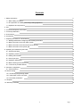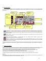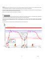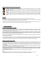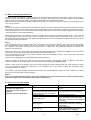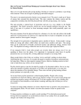
1
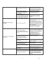
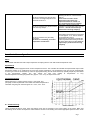
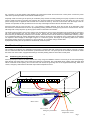
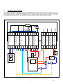
HOT WATER WOOD BOILER
ECOMAX 25, 35, 42kW
USER MANUAL
2012
Manufacturer:
1
Page
Contents
1. Safety instructions
3
1.1 Basic safety precautions
3
1.2 Fire protection in installing and using heating appliances
3
1.3 Operators and supervisors
4
2. Use
4
3. Technical description of the boiler
4
4. Technical parameters
6
5. Fuel material
6
6. Accessories
7
7. Preparing the boiler for commissioning
7
7.1 Binding standards for designing and installing the boilers
7
7.2 Boiler connection to the hot water system
7
7.3 Boiler connection to the smoke duct and chimney
9
7.4 Boiler connection to the power grid
9
8. Operating and maintaining the boiler
10
8.1 General principles
10
8.2 Operating modes
10
8.3 Adding fuel material
11
8.4 Control principle
11
8.5 Operation adjustment
13
8.6 Boiler cleaning and maintenance
13
8.7. Overview of possible defects
14
9. Controller configuration
16
9.1 Commissioning
16
10. Electric wiring
17
10.1 Conducting the patching cables
17
10.2. Description of the connection
17
10.3 Controller parameters
19
11. Disposal
19
12. Warranty Certificate
20
2
Page
1. Safety instructions
1.1
Basic safety precautions
1.
2.
3.
4.
5.
6.
7.
8.
9.
10.
11.
12.
13.
14.
15.
16.
17.
18.
19.
20.
Read carefully through the present boiler operating and maintenance manual and request adequate training from the
installer
The boiler connection must comply with the applicable regulations
Keep the boiler room tidy
Do not leave combustible articles in the vicinity of the boiler
The boiler may only be operated by persons above the age of eighteen
Do not allow children in the vicinity of the boiler
Use personal protective equipment – gloves, goggles and a cap
Use appropriate work attire avoiding easily combustible materials
Remain cautions while handling the stoking and ash pan door
Do not try to stoke with you long hair loose
Do not attach multiple appliances into one and the same chimney flue
Before leaving the boiler room, always make sure the chimney damper and the two doors are shut down
Regularly check water quantity in the system as well as the functioning of the safety equipment
Make sure the water in the system and the open expansion vessel has not frozen
Use specified fuel only
Do not leave the boiler unattended, ensure the heat power is consumed in the event the circulation pump stops
to work
In the event of boiler overheating, remove the hot firewood from the chute and allow the boiler to cool down
Any repairs and interventions with the electric wiring may reserved to an authorised person with a certificate in electric
engineering as provided for in Decree 50/75 Coll.
When handling the side covers, disconnect the boiler from the grid by pulling out the plug from the socket
Follow the warning signs
1.2 Fire protection during installation and use of heating appliances
(Excerpts from ČSN 06 1008-Fire safety of local heating appliances a heat sources)
When installing the appliances, the safe distance of at least 200 mm from any construction material must be adhered to.
The distance applies to boilers and smoke ducts located in the vicinity of degree B, C1 and C2 combustibility materials
(for the degrees of combustibility, see the Table)
The safe distance (of 200 mm) must be doubled for any boiler and smoke flues located in the vicinity of C3 degree
of combustibility material.
The safe distance must also be doubled in the event no degree of combustibility of the combustible material is identified.
The safe distance shall be halved (100 mm) in the event of use of a heat insulating non-combustible board of the thickness
of at least 5 mm located 25 mm away from the combustible material (air insulation). A screening board or a protective screen
(over the protected article) must transcend the contours of the boiler including the smoke ducts by at least 150 mm on each side
and project at least 300 mm above the top surface of the boiler. A screening board or a protective surface must also be provided
to any fixtures made of combustible materials unless the safe distance can be adhered to (such as in mobile vehicles, weekend
houses, etc., for details see ČSN 06 1008).
The safe distance must also be adhered to when placing fixtures in the vicinity of the boilers.
If the boilers are located on the floors made of combustible materials, the same must be fitted with a non-combustible heat
insulating pad reaching at least 300 mm beyond the contours of the boiler on the side of the stoking and ash pan openings and
at least 100 mm on the other sides. All materials that display A degree of combustibility may be used as non-combustible heat
insulating pads.
Degree of combustibility of construction
materials and products
A - non-combustible
B - difficult to ignite
C1 – hardly ignited
C2 – normal combustibility
C3 – easily ignited
Construction materials and products classed into degree of
combustibility
(excerpt from ČSN 73 0823)
Granite, sandstone, concrete, bricks, ceramic tiles, mortar
Fireproof plasters, etc.
Acumin, isomin, heraclit, lignos, basalt felt boards, fibreglass
boards, "novodur", etc.
Hardwood (oak, beech) hardboards, plywood,”sirkolit”, “werzalit“,
hardened paper (“umakart”)
Coniferous wood (pine, larch, spruce),particle boards, cork boards,
rubber flooring (“Industiál”, “Super”)
Fibreboard (hardboard, sololaquers, etc.), cellulose materials,
polyurethane, polystyrene, polyethylene
3
Page
1.3. Operators and supervisors
Boiler operators must follow the operation and maintenance manual. Any interventions with the boilers that could endanger
the health of the operators or those sharing the household are inadmissible!
The boilers may only be operated by persons above the age of 18 familiar with the manual and operation of the boiler.
It is inadmissible to leave children unattended near the boilers in operation.
When operating solid fuel boilers, it is prohibited to use combustible liquids to fire up as well as to increase the nominal power
while the boiler is in operation (overheating).
No combustible articles may be cast towards the stoking and ash pan openings and the ashes must be put away
in non-combustible vessels with lids.
The boilers in operation must be under frequent supervision of the operators.
The user may only carry out such repairs that consisting in the plain replacement of a spare part supplied (such as shaped fireclay
bricks, sealing cords, etc.).
While operating the boiler, caution must be exercised to ensure tightness of the doors and cleaning holes. These must at all times
be closed with care!
The user must not interfere with the structure and electric wiring of the boilers!
The boiler operators must regularly check the water filling level of the heating system and check the pressure meter function.
In the event of overheating, the operator must shut off primary air supply and collect the fire wood including the hot
charcoal into a non-combustible vessel. If the water has boiled out of the heating system, it must not be filled into
the boiler until after the latter has cooled down! Otherwise the boiler and the heating system will be damaged!
An overheated boiler and heating system may only be recommissioned after all boiler and heating systems have been
thoroughly checked (this particularly applies to all safety systems).
1.4 Type of environment
The boilers may only be used in the basic “regular environments" as specified by ČSN 33 0300. The boilers must be installed
in a boiler room where access of air required for the combustion process is ensured; the boilers must be based on a noncombustible pad.
It is prohibited to position the boilers in residential spaces (including corridors)!
Warning:
In circumstances resulting in the risk of temporary ingress of combustible gases or vapours and while performing works
that might imply a temporary risk of fire or explosion (e.g. when gluing the lino, PVC, etc.), the boilers must be put out
of use in time and well in advance. No articles made of combustible materials may be placed on the boilers and within
smaller than the safe distance away from them!
2.
Use
The ECOMAX series hot water boilers are intended for heating villas or adequate production departments. The boilers must be
installed in specified working environments only.
The boilers are supplied in basic design controlled by an operating thermostat only and with electronic control which ensures
boiler power, control of the circulation pumps and, where relevant, control of the mixing valve.
The boiler must be operated in line with the requirements for the parameters of the chimney and the heating system.
The temperature of water returning to the boiler must not be less than 65°C. We recommend using a mixing valve and a water
storage tank.
3.
Technical description of the boiler
The core of the boiler is the body welded together out of steel plates. In the upper part of the body, a chute is fitted, equipped
with a closing stoke door. The lower part of the body is fitted with a circular combustion chamber with a closing ash-pan door. The
two spaces are mutually separated by a ceramic nozzle.
An air duct is provided in the frontal part of the body, which divides primary and secondary air. In the back part, there is
an exchange, a flue gas duct, a flue gas removal branch and cleaning holes. At the very bottom of the boiler body, there is a hole
of the filling and discharge valves.
Scanning sensor (pressure sensor, temperature sensor and safety sensor) beds and the hot water branch pipe issuing
into the heating system are welded on the top of the boiler body.
The boiler body is insulated with mineral felt and clad with protective covers. A discharge fan is connected to the smoke duct
outlet, where the purpose is to remove the flue gases towards the chimney. In the upper part of the boiler body there is a cooling
loop.
In the upper part of the flue gas duct, there is a chimney dumper controlled from the frontal part of the boiler.
Control and display elements contributing to the proper functioning of the boiler are installed on the boiler casing.
4
Page
Description and drawing of the boiler
18
10
7
11
16
1
5
6
9
3
17
2
4
8
1 – Filling door
2 – Cleaning door
3 – Chute
4 – Combustion chamber
5 – Chimney dumper
6 – Door screen
7 – Hot water branch
8 – Cold water branch
9 – Door closing
10 – Control unit
11 – Main switch
12 – Safety valve branches
13 – Cleaning cap
14 – Smoke duct outlet
15 – Stack valve draw bar
16 – Pressure meter
17 – Primary air valve
18 – Upper cleaning lid
12
14
15
13
5
Page
4.
Technical parameters
Boiler type
ECOMAX 25
Nominal power
Chute volume
Water volume
Outlet branch diameter
Maximum boiler width
Maximum boiler depth
Maximum boiler height
Chute depth
Maximum log diameter
Maximum log length
Operating chimney draught
Maximum working overpressure
Maximum noise level
Efficiency
Mass
Operating voltage
Electric power requirement
Electric power requirement with electronic
control
Protection
kW
3
Dm
3
Dm
mm
mm
mm
mm
mm
mm
mm
Pa
kPa
dB
%
kg
V/Hz
W
W
ECOMAX 35
ECOMAX 42
25
120
60
160
612
850
1200
500
220
300
20-25
200
65
83
270
230/50
21
30
35
170
68
160
612
1000
1200
500
220
500
20-25
200
65
81
360
230/50
21
30
42
200
78
160
712
1120
1475
650
220
500
20-25
200
65
79
454
230/50
41
50
IP 20
IP 20
IP 20
Nominal power and efficiency were measured at 11% firewood humidity
5. Fuel material
The fuel material specified is lump wood. No wood quality is specified. It is recommended to burn lump wood cut in maximum
lengths as per the table of technical parameters. The wood must be combusted as dry as possible, with at least 15% humidity
max. Damp wood releases water when combusted, which then condensates on the walls of the boiler body and the chimney. This
results in the emergence of aggressive substances which markedly reduce the boiler and chimney life. Burning damp wood also
results in a marked boiler power reduction.
Indicative table of the calorific value of wood mass depending on the water content
Calorific value
Humidity
(%)
15
20
25
30
35
40
45
50
55
60
( kWh/kg)
Coniferous
4.329
4.035
3.740
3.446
3.151
2.856
2.562
2.267
1.973
1.678
Deciduous
4.057
3.779
3.500
3.222
2.943
2.664
2.386
2.107
1.829
1.550
6. Accessories
The following accessories are supplied along with the boiler:
Steel brush
Scraper
Discharge fan
Counterflanges
1 unit
1 unit
1 unit
2 units
Screw M8 x 25
Nut M8
Washer 8.2
Operating Manual
8 units
8 units
8 units
1 item
6
Filling valve
Gasket
Warranty Certificate
1 unit
2 units
1 item
Page
7. Preparing the boiler for commissioning
Prior to putting the boiler into operation, the conditions stipulated under the relevant ČSN must be adhered to (such as chimney
inspection and approval of fitness for purpose by the Chimney Authorities, a heating system designed calculated for this type
of boiler, completion of a heating test, etc.).
Installation of the boiler is conditioned by the connection of the controlled mixing valve in the primarily heating water circuit and
connection of a safety discharge valve, TS 130. The connection of the safety discharge value is mainly necessary in the event
of a use of an uncontrolled mixing valve in the primary heating water circuit. In the event that the specified safety discharge valve
is not used, emergency removal of the residual heat in the event of power failure needs to be ensured while designing
the heating system and installing the boiler, where the pumps and the servo-drives of the mixing valves are blocked.
At the beginning of the heating season, it is always necessary to check the filling and de-aeration of the heating system!
7.1 Binding standards in designing and installing the boilers
ČSN 06 0310 - Heating systems in buildings – Design and installation
ČSN 06 0830 - Heating systems in buildings – Safety equipment
ČSN 73 4201 - Chimneys and smoke ducts – Designing, executing and connecting fuel material consuming appliances
ČSN 06 1008 - Fire safety of local heating appliances and heat sources
ČSN 07 0240 - Hot water and low pressure steam boilers
ČSN 07 0245 - Hot water boilers with power up to 50kW
ČSN EN 13501-1 - Fire classification of construction products and building constructions – Part 1:
Classification based on response to fire test results
7.2 Boiler connection to the hot water system
The boiler shall be connected to the heating system using flanges to be welded onto the pipes of the heating system. A
gasket must be inserted between the flanges and bolted together using M8x25 bolts. A TS 130 safety discharge valve shall be
fitted. The fixture must be bolted to one of the lateral 3/4“ outlets and a measuring probe shall be inserted into the sink between
the outlets. Connect the cold water branch of the water mains to the TS 130 fixture. Connect the sanitation outlet to the other 3/4“
outlet. In the event of boiler overheating, the thermostatic valve integrated in the fixture shall open the cold water supply into
the cooling loop. After passing through the cooling loop, the cooling water flows spontaneously away into the sewerage system.
Once the boiler has cooled down, the water flow rate is automatically stopped.
Connection of the safety outlet fixture is a pre-condition to safe boiler running. The boiler may only be connected
up by an expert company or a professional heating engineer.
Safety valve connection chart
The boilers are partially protected against overheating by a safety thermostat. The thermostat switches off the fan once the water
o
temperature in the boiler exceeds 95 C (the condition being moreover indicated by the failure indicator LED). This will result
in the boiler passing into the steady heating mode and gradually reducing its power. Once the boiler water temperature drops
o
by approx. 15 C, the safety thermostat will switch the fan back on and the boiler will ramp up to the required power.
The present system of boiler protection only works reliably under the condition of steady supply of pressurised cold water
from the water mains (pay attention to domestic water plants in the event of power failures). Please also note that the safety
systems described above are only fully and reliably functional under the condition of electric power supply. Therefore, the very
issue must be addressed, for hot water systems with forced circulation, by connecting a part of the heating system to a gravity
circulation circuit with the minimum power consumed being at the level of 20% of the nominal boiler power, as a minimum
requirement.
7
Page
Chart showing connection of the boiler to the gravity circulation heating system (indicative chart with no claim
to completeness)
Chart showing connection of the boiler to the system with a pressure expansion vessel (indicative chart with no claim
to completeness)
A safety pressure valve must be used, whose opening overepressure is 180 kPa! The valve must be fitted to the hot water outlet
from the boiler, as close to the outlet pipe as possible.
Chart showing connection of the boiler to a forced circulation system (indicative chart with no claim to completeness)
For a basic design boiler without electronic controls, the circulation pump must be connected via an external control unit (pump
protection + pump switching clamp-on thermostat), which may be ordered as special boiler accessories. For an electronic control
boiler, the pump must be connected right from the boiler and is controlled by electronic controls.
8
Page
7.3 Boiler connection to the smoke duct and chimney
The boiler connection to the flue duct and chimney must correspond to the relevant standards and regulations and must
be approved by the relevant Chimney Authorities.
Smoke duct
The smoke duct must issue into the chimney vent. Unless the boiler can be connected directly to the chimney vent, the respective
extension to the smoke duct must be as short as practicable. However, adequate heating surface longer than 1 m must be
provided and it must rise towards the chimney. The smoke ducts must be mechanically firm, sealed against infiltration of flue
gases and cleanable on the inside. The internal cross section of the smoke duct must not exceed the internal cross section of the
chimney flue and it must not be tapering toward the chimney. Use of a greater quantity of smoke knuckles is not recommended.
Smoke ducts must not be conducted through other residential or utility units.
The method of executing the passages of the smoke duct though structures made of combustible materials are given in Annexes
2 to 3 to the ČSN 06 1008 standard, and are mainly suitable for mobile devices, wooden weekend houses, etc.
Chimney
The chimney must be designed for such a size as to ensure that the chimney vent develops adequate draught at all times and
safely removes the flue gas into the atmosphere. We recommend that the vent be lined.
Indicative chimney dimensions recommended for ECOMAX boilers:
20 x 20 cm
min. height 7 m
15 x 15 cm
min. height 12 m
diameter 20 cm
min. height 8 m
In the event of an excessive chimney draught (the chimney draught automatically lifts the primary air flap allowing the boiler
to burn even after the fan has been put out), the proper functioning will call for installation of a draught controller.
The exact chimney size and structure determination is determined by ČSN 73 4201 and ČSN 73 4210.
7.4 Boiler connection to the power grid
The boilers must be connected to the 230 V / 50 Hz power grid by a network cord and a plug. The socket connection must
conform to the applicable ČSN standards.
An unprofessional intervention in the electric wiring of the boiler will result in the latter becoming damaged and may
lead to fatal injuries!
8. Operating and maintaining the boiler
Prior to commissioning the boiler, the present boiler operation and maintenance manual must be read carefully through; where
a boiler with electronic controls is being commissioned, the relevant manual covering the electronic controls must also be carefully
read through.
8.1 General principles
•
•
•
•
•
•
•
•
•
Bearing in mind the safety of all users of the system, read carefully through the present safety precautions and follow
them.
Prior to using the system, become familiar with the User Manual and adhere to the recommendations indicated therein.
Use the equipment exclusively for the purpose for which it is intended using the method described.
The elements of the system are powered by grid voltage. When handling these elements, pay attention to your safety
and protect yourselves against electric shock injuries. Do not handle the system elements with your hands wet and
protect the equipment against contact with liquids. Penetration of water, other liquids or foreign particles into the
elements of the equipment may cause serious malfunctions with its short circuits and leakage currents with severe
implications for user safety and functioning of the control or heating system.
The users must not uninstall any system elements. Some system elements are powered up by grid voltage – risks
of electric shock injuries.
If any part of the equipment falls down, allow the instrument to be checked by a professional before putting the same
back into operation. Damage not visible to the naked eye may too jeopardise user safety.
Do not use system elements that exhibit the signs of damage.
When cleaning or maintaining the elements, do not use combustible liquids, their use may lead to emergence of fire.
Use original accessories or accessories specified by the manufacturer only.
Al parts of the equipment must be positioned and kept out of reach of children and toddlers; prevent their being damaged
accidentally by children. Damage to an element may lead to a severe injury of the child.
9
Page
8.2 Operating modes
o
We recommend setting the boiler water (primary circuit) to the temperature of at least 70 C. The low operating boiler
temperature supports condensation of tar components on the boiler walls, thus bringing out corrosion which substantially reduces
the boiler life.
Fan power
Fan blocking
Operating mode
of the controller
Manual mode,
the fan and
circulation pump
switched on
Pump operation
Stoking
Running
Lack of fuel material
Manual operation
Change in value + -
Confirmation buttons
Boiler output water temperature
Outdoor
temperature
Setting the required
temperature for the basic
design
Selectin of an
equithermal curve for
equithermal design with
an outdoor sensor
Fan blocking – in order to make the firing up of an extinguished boiler more comfortable, the flue gas extraction fan
operation may be interrupted thus avoiding having the match blown out by the undesired draught of the flue gas fan.
Once the boiler door is opened, the flue gas fan is always switched to full power so that no flue gas leakage into the
boiler room occurs.
Manual operation – switches the fan and circulation pump regardless of the operating mode of the boiler and output
water boiler temperature.
Setting the required temperature – for basic design only; the controlled ensures supplies of heating water
into the system according to the user-set temperature.
Selection of equithermal curve – for equithermal design with an outdoor temperature sensor only. The user defined
parameters of slope and heel point determine the nature of the equithermal curve, according to which the output water
boiler temperature is calculated.
Pressing the OK button in the basic menu displays the history of the controller’s operational values. The buttons may be used to
change the resolution of the chart and the + - buttons are used to move across the time axis. The chart memory is roughly for 4
hours.
8.3 Adding fuel material
Additions of the fuel material take place via a stoke door after opening the filling door. Handle the door with the chimney dumper
open only. Given a proper function of the boiler, these conditions are met automatically once the following steps are taken:
Open the chimney dumper with a draw bar. Wait for approx. 1 minute before slowly opening the filling door.
Tilt down the screen with a fire hook and assess the remaining lumps of firewood. Put more wood on the hot ashes.
Close the screen. Close the filling door and retighten the screw cap with caution.
Use the draw bar to close the chimney dumper. The boiler will gradually ramp up to the required power.
The boiler combustion time with the full chute depends on the humidity of the fuel material and the power consumed.
Warning:
After the stoking, the chimney dumper must be closed! An open chimney dumper will allow uncontrolled burning of the boiler due
to continuous intake of secondary air. Boiler overheating is imminent!
10
Page
Notice:
In the inhibited mode, the firewood does not burn but rather smoulders and imperfect combustion occurs, releasing smoke gases
at an inappropriate composition. The boiler gets clogged and tars in the chute thus reducing its life.
In terms of heating ecology and boiler life, excessive heat energy or scheduling of the heating process should be addressed
by means of storage tanks and their controlled discharging.
Make sure the firewood is as dry as practicable, see Chapter 5.
8.4 Control principle
The controller covers the automated burning process in keeping with the required parameters. In all modes (basic, equithermal,
controlled) fan power is controlled based on the required boiler water output temperature.
As a default, we recommend operating the boiler in automatic mode. As a result, the control of the extraction fan is automated
without the need for an intervention by the user. The only setting that must be done is that of the maximum output boiler water
temperature.
temperautre
The burning process is divided into three operating modes shown in the image below.
Condensation temperature Required temperatre
teplota
Limit temperature (fan off)
Firing up
Off
Stoking fuel
material
(door contact)
Stoking fuel
material
(door
contact)
Operation
On
Inhibition Firing
Operation
On
time
Off
11
Page
Operating statuses of the boiler in automatic mode
1)
2)
3)
Firing up – With insufficient heating water temperature the circulation pump is switched off. The fan slowly increases
its power until the heating water temperature exceeds the condensation temperature. Then it passes
into the operation stage
Operation – The boiler power is modulated in such a way as to ensure the boiler output water temperature is
as close to the required temperature as possible. The circulation pump is on and hot water is supplied to the heating
system.
Inhibition – With the heating water temperature decreasing under the condensation temperature, the boiler switches
off the circulation pump and fan. The controller will wait for the operator to stoke some more fuel material.
After the boiler door is opened, firewood stoked and the boiler door closed the controller goes back to the firing up
stage.
Inhibition
For all configurations, a remote spatial thermostat with a switching contact may be connected to the controller.
(Not heated up – contact closed, heated up – contact open). Once the boiler heats the given room up and switches the spatial
thermostat open, the boiler will pass to inhibition shutting down the circulation pump.
Caution! The thermostat constant must be separated, potential free. The thermostat must not switch other voltages, and under no
circumstances must it switch 230VAC network voltage. Otherwise, controller damage is imminent.
8.5 Operation adjustment
Adjusting the operating draught of the boiler
The boiler has been adjusted to the specified chimney draught at the production plant (depending on the type of the boiler,
20-25 Pa – see the Technical parameters of boilers). The size and mass of the primary air flap shutting off air supply to the boiler
thus regulating the combustion corresponds to this.
In the event the chimney exhibits a higher than specified draught, a greater consumption of primary air and, by inference, a more
rapid fuel material loss will occur causing the boiler efficiency to drop. The boiler is also more difficult to control and the standby
time in “hot reserve” is reduced. The problem may be solved by installing a draught controller between the boiler and the chimney.
The draught controller may be ordered as special boiler accessories.
No other ways of adjusting the boiler are admissible and where necessary, the above may only be carried out
by an authorised professional.
In the event that the chimney does not reach the specified draught, the boiler may not achieve the required power either, which
may either impair the combustion process or even lead to the boiler releasing the smoke into the space (especially whilst stoking).
The problem needs be addressed by adjusting the chimney following agreement with a professional chimney company.
Adjusting the stoking and ash pan door
The rough adjustment of the door is completed at the production plant. Any changes that may develop in transport must be
removed by the boiler operator prior to commissioning the same. Similarly, adjusting the door with the boiler in operation (such as
in the event of combustion smoke penetrating into the room with the door closed or due to the wearing or the need f
or replacement of the sealing cord) belong to the fundamental maintenance interventions on the boiler carried out
by the operators.
The actual adjustment shall be completed after releasing the M12 nuts with a pipe wrench to be inserted in the holes in the side
encasing (on the hinge side). That will release the sliding hinge of the door.
Slightly open the door and press on it at the hinge locations to reduce the gap between the sealing cord and the boiler frame.
An appropriately adjusted door must have the same hinge gap over the entire length of the sealing edge; once the door is closed,
the sealing edge must abut across the entire surface of the frame and it must be possible to freely place the hook of the screwed
cap into the grip at the door frame.
After this adjustment has been done, re-tighten the M12 nuts of the sliding hinge with a pipe wrench.
Notice:
Never retighten the door with force; otherwise the screwed cap could be damaged and the sealing cord cut through!
If possible, position the boiler in such a way as to ensure easy access to the holes in the side plates.
12
Page
8.6 Boiler cleaning and maintenance
The boiler should be cleaned at a greater frequency as tar and ash deteriorate heat transfer, which reduces boiler efficiency.
The ash from the chute shall be swept away through the opening in the nozzle into the combustion chamber. Tar components
must be removed from the boiler walls by a scraper and also swept into the combustion chamber.
Make sure the tar does not flow or impurities falling to the air flap. If so, release the flap and scrape the tar. The air flap must be
easy to open and close.
Notice:
The primary air flap is an important boiler control element. Therefore, it must be regularly checked and the air duct space must be
kept clean! The fallen lumps of wood prevent opening the flap and thus make it impossible to achieve the required boiler power.
At the same time, the tar on the walls of the air duct hinders reliable closure of the air flap thereby bringing about uncontrolled
combustion that may cause boiler overheating!
Sweep away the ash from the combustion chamber. If possible do not remove the A-shaped adapting piece. In the event that
the shaped piece must be removed with a view to allowing a more thorough cleaning of the boiler, or due to the need for
the replacement of the shaped piece, while fitting the shaped piece back into the combustion chamber, it must be moved all the
way to the back wall of the chamber.
Notice:
If the shaped piece does not perfectly abut to the back wall of the combustion chamber, the hot flue gases pass through
from the combustion nozzle directly to the flue gas exchanger, outside of the post-combustion chamber. This deteriorates
the combustion process (the quantity of the flue gases does not correspond to the guaranteed values) and the power and
efficiency of the boiler drop!
Unscrew and remove the upper cleaning lid and clean the exchanger space using a steel brush supplied as part of the boiler
accessories. Use a scraper to clean the entire flue duct including the chimney flap.
Check the tightness of the chimney flap. Where necessary adjust the flap position in such a way so that it may abut evenly
to the vent from the boiler chute.
Check or remove the gaskets of the cleaning lids and screw them back on.
Check the gaskets of the filling and ash pan doors and where necessary replace them. Check the tightness of the doors
at closure. If either door is not tight, adjust. Treat the hinges and caps regularly with graphite grease.
Perform a visual check of all mechanic parts of the boiler including the ceramic shaped pieces and where necessary, replace
them. We recommend trusting the replacement of any damaged parts of the boiler including the combustion nozzle
to a professional service company.
The condition of the heating system must be checked at least once a week (tightness, quantity of water, condition of circulation
pumps, and or the eventuality of system freezing).
Notice:
In the course of the cleaning procedure, the ceramic shaped piece must be handled with care. Careless treatment and/or
a fall from a height will cause damage and will require a replacement.
8.7 Overview of possible defects
Description of malfunction
Probably cause
Removal method
The boiler burns poorly, exhibiting a
low power; the flame in the
combustion chamber is dull and
yellowish.
Excessive firewood consumption.
Fuel material with humidity above 15 %
Use firewood at maximum humidity
of 15 %
Large and short lumps of wood (average
above 150mm and length shorter by over
200mm compared to the chute depth).
Primary air flap off.
Flap not fully closed.
Nozzle clogged.
Nozzle damage.
13
Use wood lumps of correct dimensions
Clean and release the flap.
Check the flap tightness, clean the flap,
check the condition of the return spring
and position of the flap draw bar. Replace
if necessary.
Clean and remove any articles fallen
through to the nozzle slot, or into the
suction holes.
Replace the nozzle.
We recommend trusting the job to a
specialised service company!
Page
Clogged secondary air vents to the
nozzle.
Clogged or overly contaminated
exchanger space (the combustion
process gets better once the ash pan
door is opened).
Fire clay adapting piece of the
combustion chamber (roof) not moved all
the way to the back wall of the chamber.
In this case the boiler burning is sound
yet the boiler displays a reduced power
and increased firewood consumption.
Boiler hard to control, getting
overheated.
Open or stuck primarily air flap.
Excessive chimney draught –
the chimney draught spontaneously
opens the primary air flap (the flap keeps
flapping).
Boiler is hard to control and gets
overheated.
Open chimney flap – the boiler sucks air
in, through the secondary air duct and
burns in a way which is entirely
uncontrollable using the traditional
means.
Water does not circulate in the boiler or
heating system.
Safety thermostat failure – the boiler (fan)
is in operation despite the water
o
temperature exceeding 95 C
Closed or insufficiently opened mixing
valve.
Oversized boiler
The fan does not work
The fan is switched off by the fan switch.
The fan is off by the operating thermostat
(within the electronic controls).
14
Clean the air duct between the fan and
the nozzle. This must be done after
removal of the front fan cover and the fan.
We recommend trusting the job to a
specialised service company!
Clean the exchanger including the bottom
vent leading from the combustion
chamber to the tube sheet.
Check the position of the ceramic
adapting pieces in the combustion
chamber.
Clean and release the flap. The front
boiler cover and the actual primary air flap
need to be removed.
When fitting them back on, make sure to
centre the flap well within the air duct.
The flap axis revolves along with the flap,
and therefore, increased caution must be
exercised when tightening the securing
nuts on the flap axis.
We recommend trusting the job to a
specialised service company!
Switch the fan by the manual switch and
wait for the chimney to cool down entirely
(about 1 hour). If the boiler temperature
keeps rising, and you can still heat the
flap flapping, a draught controller needs
to be installed. May be ordered as
optional boiler accessories.
We recommend trusting the job to a
specialised service company!
Shut the chimney flap off, check for its
condition and functioning.
Check water quantity in the system,
condition of the pump and its functioning
Clean the pump filter.
Must be carried out by a specialised
service company!
Check the function of the mixing valve.
Where necessary, disconnect the mixing
valve from the drive and perform an
emergency manual opening of the valve.
Adjust the heating system. We
recommend using storage tanks.
Turn the switch on.
Set a higher temperature on the operating
thermostat (within the electronic controls)
In the event of a thermostat failure
(electronic controls), replacement is
required by a professional service
company!
Page
The fan is switched off by the sub-limit
thermostat. The boiler temperature has
o
decreased under 50 C.
The fan is switched off by the limit switch
of the chimney dumper.
The fan is switched off by the safety
thermostat.
The boiler is overheated – the boiler
o
temperature exceeds 95 C.
9
Set another temperature level for
switching the fan off – see the service
settings.
In the event of a failure of the
thermostat or the switch, the
replacement must be carried out
by a professional service company!
The stroke of the limit switch must
adjusted or the faulty limit switch must be
replaced – must be carried out by a
professional servicing company!
The heating system must be cooled down
o
to under approx. 75 C. The fan will then
go automatically back on.
Unless the fan goes back on despite the
boiler temperature decreasing under 65°,
the safety thermostat has failed-must be
replaced by a professional servicing
company!
Controller configuration
Basic
The controller maintains the boiler output temperature in keeping with the user defined fixed temperature value.
Equithermal
The controller must be equipped with an outdoor temperature sensor. The controller will calculate the required boiler output water
temperature based on an equithermal curve and the outdoor temperature. The equithermal curve must be set experimentally
for each type of the site to be heated up. Given its appropriate setting, the site will be heated up optimally despite any fluctuations
in the temperatures outside. The user selects the heel point (ideally at temperatures of 0°C),
with the temperature outside going below zero (approx. -10 to -5°C), the slope must be set.
Controlled steering
Allows steering by a superior system using a 0-10V signal. This
principally involves equithermal control where the outside temperature is
simulated using the given external signal. 0V= +20°C, 10V= -20°C.
9.1 Commissioning
Having reviewed all electric parts, check the heating circuit with an emphasis on the proper setting of the valves. Make sure
the heating circuit contains an expansion vessel and there is water in the heating circuit at the appropriate pressure value. Check
15
Page
the connection of the flat patching cable between the input/output module and the Ecomax control panel. Connect the power
cable of the input/output module to the 230VAC distribution grid.
Physically check the running of the primary air circulation pump and the secondary heating circuit pump if present in the heating
system. Check the running of the flue gas extraction fan. Once the boiler door is opened, the fan must ramp up to 100 % of its
power. Draught must be apparent near the boiler door towards the chimney. Once the control button with the image of the fan
crossed out is pressed, the flue gas extraction fan must stop. No draught should be felt near the boiler door then.
Stack the boiler with dry wood and fire it up – see chapter 8.3 Adding firewood. Once the fire has lit up reasonably, close
the boiler door and unblock the fan function by repeatedly pressing the button showing the symbol of the crossed-out fan. The fan
will slowly start to ramp its power up, fanning up the flames in the boiler’s fire chamber.
The boiler’s primary heating circuit pump and the flue gas extraction motor must be electrically interconnected at the customer’s
site. The interconnection may only be carried out by a person with the relevant electric engineering qualification. Space
thermostat may be individually connected to the controller, where the former must be fitted with a potential-free switching contact;
for an equithermal design an outdoor temperature sensor must be connected, to be positioned on the northern side of the building
not exposed to direct sunlight, at the height of approx. 2 m above the ground. The length of the patching cable for the outdoor
temperature sensor may be 15 m maximum, or 25 m maximum, for connection using a coaxial cable.
Equipotential bonding must be provided on all electrically conductive parts.
10
Electric wiring
The controller is powered by the 230V/50Hz network using a network cable with a bent plug and a CEE7/7 connector. The IEC
320 C13 network socket case accommodates a protective 2A/T tube fuse. The power part of the controller is screwed on inside
the sheet cover of the boiler, equipped with bushings and a flat patching cable for the Ecomax control panel.
10.1
Conducting the patching cables
Fix the input/output module to the boiler shell in such a way using two installation screws in such a way as to ensure the passage
holes through the sheet casing of the boiler and module are in alignment. Non-combustible silicon cables under the boiler shell
will be conducted via this opening. This concerns the main switch, the grounding wire for the equipotential bonding, boiler door
contact, emergency thermostat and the boiler output water temperature sensor.
P L N P N
E
E
MS
P N
E
MC
K K T1 T1 P N M
V
P P
E
G TS G T G R G U
T
A
Main switch
Door contact
Emergency thermostat
16
Boiler output waster
temperature sensor
Page
10.2
Description of the connection
The controller is powered up by 230V/50Hz network using a network cable with a bent plug and CEE7/7 connector. The IEC 320
C13 network socket case accommodates a protective 2A/T tube fuse. The power part of the controller is screwed onto the inside
of the boiler’s sheet case, equipped with passages and a flat patching cable for the Ecomax control panel. The opening
in the bottom right-hand side corner of the base serves the conducting of the cabling under the boiler’s sheet shell.
1A/T
PE L
N PE N MS PE N MC KP KP T1 T1 PE N MV
G TS G TA G
R
G UT
L
Space thermostat contact
R
0-10V control signal
(for controlled design)
Outodoor temerature
sensor
G TS G TA G
Boiler output water
temperature sensor
Flue gas extraction fan
motor
Safety thermostat
Boiler door contact
Primary circuit circulation
pump
N PE N MS PE N MC KP KP T1 T1 PE N MV
Secondary circuit
circulation pump
Power supply
PE L
G UT
L
fuse
17
Page
10.3
Controller parameters
Ecomax input/output module
Size:
Supply voltage:
Maximum current consumption:
Maximum input power:
Temperature sensor input :
Safety thermostat input:
Open door sensor input:
Fan motor output:
Circulation pump output:
Sec. circulation pump output:
Protection
Protection to EN60529:
Operating temperature:
Designed to:
EMC tested to:
215×132×83 (width×height×depth)
230VAC
2A
260VA
2 inputs for DS18B20 digital temperature sensors
230VAC normally closed contact
230VAC normally closed contact
230VAC triac,
max. 40VA
230VAC relay,
max. 100VA
230VAC, permanently closed
max. 100VA
2A blow fuse.
IP2X
up to 60°C
EN60730-1 2:2001
EN 61000-4-2, EN 61000-4-3, EN 61000-4-4,
EN 61000-4-5,EN 61000-4-11, EN 55022
Environment to ČSN 332000-3:
AA5, AB5, AD1, AE1, AF1, AK1, AM1, BA1, BE1
Intended for base of degree of combustibility: B, C1, C2 a C3.
For all conductive parts of the boiler, equipotential bonding must be performed with potential PE.
Ecomax control panel
Size:
Supply voltage:
Maximum input power:
Protection to EN60529:
Operating temperature:
Designed to:
EMC tested to:
136×72×25 (width×height×depth)
24VDC
5VA
IP2X
up to 60°C
EN60730-1 2:2001
EN 61000-4-2, EN 61000-4-3, EN 61000-4-4,
EN 61000-4-5,EN 61000-4-11, EN 55022
Environment to ČSN 332000-3:
AA5, AB5, AD1, AE1, AF1, AK1, AM1, BA1, BE1
Intended for base of degree of combustibility: B, C1, C2 a C3.
11
Disposal
No hazardous materials requesting special waste treatment were used in the making and packing of the boiler.
The packaging consists of a wooden transport pallet, a paper carton and a flexible packing foil. After the disassembly the paper
and the pallet must be burned in the boiler and the packing foil handed over to the local municipal waste landfill.
At the end of the boiler life, the same must be dismantled and the sorted material submitted to the collection yards as per
the individual types of materials and in keeping with the applicable regulations.
Used boiler material:
-
steel sheet
grey iron
aluminium allow in the fan body
glass fibre insulation
refractory concrete
synthetic or powder paint coat
electronic components
copper conductors
silicon conductor insulation
18
Page
12. WARRANTY CERTIFICATE
covering ECOMAX 25, ECOMAX 35, ECOMAX 42 hot water boiler, fabrication no.
Manufacturer: OPOP spol. s r.o., Valašské Meziříčí
Tel.: 571 675 589, Fax.: 571 611 225
Shipped from the plant:_________________________________________
Warranty terms:
The present warranty sheet contains quality and completeness certificates. The manufacturer confirms that the product has been checked and
proved to conform, with its design, to the technical conditions and ČSN EN 303-5. We provide the warranty for the quality, function and
workmanship of the boiler during 24 months of the sale to the respective customer, yet for the maximum of 30 months from removal
from the production plant, namely by pledging to remove any defects demonstrably due to faulty material, design or workmanship within as
little time as possible at our own expense, provide that the boiler:
•
•
•
•
•
•
is in regular technical condition as stipulated in the operating manual
is connected to a chimney vent to ČSN 73 4201:1989
has not been mechanically damaged with force (there has been no unauthorised interventions save for any action provided
for in the Operating Manual)
the chimney draught to ČSN must correspond to the value indicated in Table 2, depending on the boiler type
the customer submits the present warranty certificate, duly filled in, when lodging a complaint
the manufacturer’s instructions governing the use of pressure expansion vessels have been adhered to
Note:
When notifying a defect, the present Warranty Certificate must be submitted at all times, and the exact address and the circumstances, in which the defect
occurred must be indicated. Our company will decide on the method and place of repair.
Technical check completed on________________________
Sold on ______________________
Note:
For the steel weldment – we guarantee its lasting tightness during 60 months from removal from the production plant. The present warranty
is preconditioned by the fact that no pressure expansion vessel has been used in the heating system and the leakage has occurred due to
low-quality material or welding work. The warranty cannot be enforced for faults down to the operators. If the warranty claim is
acknowledged during an extended warranty term, we will provide the user with a replacement steel weldment using unit transport or
personal delivery. The costs associated with the transport, replacement and return of the faulty weldment to the production plant shall be
borne by the user. Unless the faulty weldment is returned to the production plant within 30 days of its dispatch or handover
of a replacement weldment, the weldment will be charged to the user at its full value.
A warranty term of 24 months from collection applies to the weldment replaced under the extended warranty term, i.e. 60 months.
The boiler weldment is treated with black water paint which may lead to the peeling of the coat. The peeling coat shall have no effect
on the function of the boiler. After the first firing up, the coat will get burn out.
19
Page
Procedure for lodging a complaint:
1)
Submit the warranty certificate with a document attesting to the payment of the product either in person, by post or fax.
2)
Report the exact address or telephone and indicate the circumstances in which the defect occurred.
3)
The service engineer will let the user know of the method of dealing with the complaint:
a)
sending the complaint part for replacement
b)
in the event the procedure under point a) is impossible, the manufacturer shall be entitled to select the method, deadline and
execution of the repair by their service engineer or contractual partner
c)
the user must allow the producer to complete the repair under point b)
d)
unless the user allows access to the installation with a view to conducting the repair, the manufacturer shall consider the complaint to
have been completed
e)
in the event the defect proves impossible to be removed, the user shall be entitled to a replacement of the defective part
f)
in the event the complaint proves unjustified, i.e. the defect or leakage of the weldment is not confirmed by the service engineer
the lodger of the complaint will be charged with the costs associated with the inspection and journey to the user’s site
g)
where it becomes necessary to speed the complaint up, please contact the manufacturer’s servicing engineer at the following phone
number: 571 675 252 or 602 743 970
Dear Customer,
We are very happy for you to have opted for our product. The decision entitles to a 10% discount on spare parts. In order for you
to obtain the advantages above, you must fill in the registration card and send it to our address:
OPOP spol s r.o.
Obchodní oddělení
Zašovská 750
757 01 Valašské Meziříčí
After we receive your filled out form, we will provide you with your Customer Card by return of post, which makes you eligible
for the discounts on the price of the spare parts from the manufacturer. When ordering spare parts you must always mention
your Customer Card number.
Thank you for your trust.
Cut here and send to our address
……………………………………………………………………………………
14. REGISTRATION CARD
Name…………………………..
Product fabrication no.…………………….
Surname………………………… Salesman…………………………………..
Street and no. ……………………..Type of product……………………………….
Town……………………………
Postcode……………………………..
Phone number (optional)…………………………
E-mail ……………………………
Signed………………………………………………
20
Page
OPOP, spol. s r. o.
Zašovská 750
757 01 Valašské Meziříčí
Bank details:
Komerční banka a.s., account no.:1608851/0100
Reg. no.: 47674105, VAT no.: CZ 47674105
Phone: Sales Dept: 571 675 589, Secretariat: 571 611 250, Production: 571 675 405
Sourcing: 571 675 114, Finance: 571 675 472
Fax. 571 611 225
21
Page