1
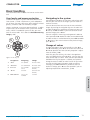
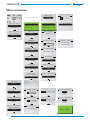
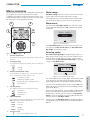
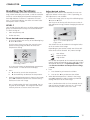
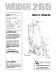
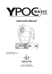
User manual
CONDUCTOR
LEVEL 2
User manual
1
CONDUCTOR
2
Swegon reserves the right to alter specifications
20100308
www.swegon.com
CONDUCTOR
Contents
About CONDUCTOR . . . . . . . . . . . . . . . . . . . . . . . . . . . . . . . . . . . . . . . . . . . 4
Applications . . . . . . . . . . . . . . . . . . . . . . . . . . . . . . . . . . . . . . . . . . . . . . . . . . . . . . . . . . . . . . . . . . . . . . . . 4
Operating modes . . . . . . . . . . . . . . . . . . . . . . . . . . . . . . . . . . . . . . . . . . . . . . . . . . . . . . . . . . . . . . . . . . . . 5
Functions . . . . . . . . . . . . . . . . . . . . . . . . . . . . . . . . . . . . . . . . . . . . . . . . . . . . . . . . . . . . . . . . . . . . . . . . . . 5
Overview. . . . . . . . . . . . . . . . . . . . . . . . . . . . . . . . . . . . . . . . . . . . . . . . . . . . 6
Controller . . . . . . . . . . . . . . . . . . . . . . . . . . . . . . . . . . . . . . . . . . . . . . . . . . . . . . . . . . . . . . . . . . . . . . . . . . 6
Room unit. . . . . . . . . . . . . . . . . . . . . . . . . . . . . . . . . . . . . . . . . . . . . . . . . . . . . . . . . . . . . . . . . . . . . . . . . . 6
Installation . . . . . . . . . . . . . . . . . . . . . . . . . . . . . . . . . . . . . . . . . . . . . . . . . . 7
Preparations . . . . . . . . . . . . . . . . . . . . . . . . . . . . . . . . . . . . . . . . . . . . . . . . . . . . . . . . . . . . . . . . . . . . . . . . 7
Product marking . . . . . . . . . . . . . . . . . . . . . . . . . . . . . . . . . . . . . . . . . . . . . . . . . . . . . . . . . . . . . . . . . . . . . 7
Step 1: To install the controller . . . . . . . . . . . . . . . . . . . . . . . . . . . . . . . . . . . . . . . . . . . . . . . . . . . . . . . . . . 7
Step 2: To connect the peripheral units . . . . . . . . . . . . . . . . . . . . . . . . . . . . . . . . . . . . . . . . . . . . . . . . . . . . 8
Step 3: Starting up . . . . . . . . . . . . . . . . . . . . . . . . . . . . . . . . . . . . . . . . . . . . . . . . . . . . . . . . . . . . . . . . . . . 9
Step 4: To install the room unit . . . . . . . . . . . . . . . . . . . . . . . . . . . . . . . . . . . . . . . . . . . . . . . . . . . . . . . . . 10
Basic handling. . . . . . . . . . . . . . . . . . . . . . . . . . . . . . . . . . . . . . . . . . . . . . . 11
User levels and access protection. . . . . . . . . . . . . . . . . . . . . . . . . . . . . . . . . . . . . . . . . . . . . . . . . . . . . . . . 11
Navigating in the system . . . . . . . . . . . . . . . . . . . . . . . . . . . . . . . . . . . . . . . . . . . . . . . . . . . . . . . . . . . . . . 11
To change values. . . . . . . . . . . . . . . . . . . . . . . . . . . . . . . . . . . . . . . . . . . . . . . . . . . . . . . . . . . . . . . . . . . . 11
Menu overview. . . . . . . . . . . . . . . . . . . . . . . . . . . . . . . . . . . . . . . . . . . . . . 12
Overview . . . . . . . . . . . . . . . . . . . . . . . . . . . . . . . . . . . . . . . . . . . . . . . . . . . . . . . . . . . . . . . . . . . . . . . . . 12
Main image . . . . . . . . . . . . . . . . . . . . . . . . . . . . . . . . . . . . . . . . . . . . . . . . . . . . . . . . . . . . . . . . . . . . . . . 13
Main menu . . . . . . . . . . . . . . . . . . . . . . . . . . . . . . . . . . . . . . . . . . . . . . . . . . . . . . . . . . . . . . . . . . . . . . . . 13
Entering codes . . . . . . . . . . . . . . . . . . . . . . . . . . . . . . . . . . . . . . . . . . . . . . . . . . . . . . . . . . . . . . . . . . . . . 13
Service menu . . . . . . . . . . . . . . . . . . . . . . . . . . . . . . . . . . . . . . . . . . . . . . . . . . . . . . . . . . . . . . . . . . . . . . 14
Settings . . . . . . . . . . . . . . . . . . . . . . . . . . . . . . . . . . . . . . . . . . . . . . . . . . . . . . . . . . . . . . . . . . . . . . . . . . 14
Handling the functions . . . . . . . . . . . . . . . . . . . . . . . . . . . . . . . . . . . . . . . 15
To set the desired room temperature. . . . . . . . . . . . . . . . . . . . . . . . . . . . . . . . . . . . . . . . . . . . . . . . . . . . . 15
Contents
To adjust the desired airflow . . . . . . . . . . . . . . . . . . . . . . . . . . . . . . . . . . . . . . . . . . . . . . . . . . . . . . . . . . . 15
Advanced airflow and temperature settings . . . . . . . . . . . . . . . . . . . . . . . . . . . . . . . . . . . . . . . . . . . . . . . 16
System information . . . . . . . . . . . . . . . . . . . . . . . . . . . . . . . . . . . . . . . . . . . . . . . . . . . . . . . . . . . . . . . . . . 17
Alarms . . . . . . . . . . . . . . . . . . . . . . . . . . . . . . . . . . . . . . . . . . . . . . . . . . . . . . . . . . . . . . . . . . . . . . . . . . . 17
To change the Modbus address . . . . . . . . . . . . . . . . . . . . . . . . . . . . . . . . . . . . . . . . . . . . . . . . . . . . . . . . 18
To connect the units . . . . . . . . . . . . . . . . . . . . . . . . . . . . . . . . . . . . . . . . . . . . . . . . . . . . . . . . . . . . . . . . . 18
To test the radio connection . . . . . . . . . . . . . . . . . . . . . . . . . . . . . . . . . . . . . . . . . . . . . . . . . . . . . . . . . . . 18
Language setting . . . . . . . . . . . . . . . . . . . . . . . . . . . . . . . . . . . . . . . . . . . . . . . . . . . . . . . . . . . . . . . . . . . 19
”First open” function . . . . . . . . . . . . . . . . . . . . . . . . . . . . . . . . . . . . . . . . . . . . . . . . . . . . . . . . . . . . . . . . 19
Temperature calibration . . . . . . . . . . . . . . . . . . . . . . . . . . . . . . . . . . . . . . . . . . . . . . . . . . . . . . . . . . . . . . 19
3
Swegon reserves the right to alter specifications.
20100308
www.swegon.com
CONDUCTOR
About the CONDUCTOR
CONDUCTOR is a control system for the individual
control of the room temperature and airflow, especially
designed for partitioned offices and hotel rooms. The
control system consists of a controller and a room unit,
both with built-in temperature sensors (the sensor in the
controller is only used if room unit is not present in the
room). The controller is equipped with inputs for connection of a condenser sensor, window contact or other
normally closed contact, and outputs for the connection
of an actuator for valves and air dampers.
The instructions in this installation and operation manual
are intended for you who are accountable for the local
climate system (LEVEL 2) and they describe how you:
•
connect, start up, and adjust the CONDUCTOR RE
controller and the CONDUCTOR RU room unit,
•
easily adjust the heating, cooling and airflow by
means of the room unit, and
•
configure the functions and settings of the system.
W1
W1 is a standard solution for offices, mainly designed for
partitioned offices, but which also can be used in large
rooms, as with open-plan offices. The application is suitable for so called CAV systems (Constant Air Volume),
which implies that the airflow in the room is constant and
that no damper actuators are needed. Only two outputs
are used, one for actuators that control cooling and one
for actuators that control heating. There is provision for
connecting a condensation sensor and a temp sensor.
Table 1. Operating conditions for application W1
Condensation
Cooling
Heating
Yes
Off
Normal
No
Normal
Normal
Applications
W3
These instructions deal with two different applications:
W1 and W3. W indicates that the two applications are
applicable to water-based climate systems.
The W3-application can be used either for offices or for
hotel rooms. It is designed for systems with variable airflow (VAV) with both supply air and extract air. Four outlets are used in order to control heating, cooling, supply
and extract air. The damper motors are adjusted depending on the generated airflow and duct pressure in both
the supply and extract air ducts. Three inputs are used;
for condensation sensors, window contacts and presence
detectors. The principal is to use minimal, normal or high
airflow, depending on presence and sensor status.
A water-based system provides the room with waterbased heating and cooling. The air-based systems, which
can be controlled in W3 by means of connected damper
actuators, are only used to satisfy the demands on air
quality, while the temperature of the supply air and
extract air is kept constant.
Depending on the status of connected sensors, the
controller adjusts the outputs from any of several possible
operating conditions. The various operating conditions
described here are based on the presence of occupants
in the room and the status of the window contact and
condensation sensor.
Table 2: Operating conditions for application W3
Presence
Window
Condensation
Cooling
Heating
Supply air
Extract air
Yes
Open
Yes
Off
Frost protection
Min.
Min.
Yes
Open
No
Off
Frost protection
Min.
Min.
Yes
Closed
Yes
Off
Normal
Max.
Max.
Yes
Closed
No
Normal
Normal
Normal
Normal
No
Open
Yes
Off
Frost protection
Min.
Min.
No
Open
No
Off
Frost protection
Min.
Min.
No
Closed
Yes
Off
Normal/Energy saving
Min.
Min.
No
No
No
Normal
Normal/Energy saving
Min.
Min.
4
Swegon reserves the right to alter specifications
20100308
www.swegon.com
CONDUCTOR
Operating modes
The controller has six operating modes: One manual
mode, MAN, three automatic modes, AUTO, ECON and
BOOST, as well as one standby mode, STOP, and an emergency mode, EMERG.
Manual control
Whenever the CONDUCTOR registers the presence of
occupants in the room (in response to signals from a presence detector or a key card reader), the user can regulate
the temperature and airflow rate by means of the room
unit. When the user enters a new desired value, the
controller switches over to the manual operating mode
(MAN).
For application W3, you can manually adjust the airflow
to one of three different levels (see Set the desired airflow, p. 14). The controller controls the damper motors
which operate the supply air and extract air dampers by
means of three different voltage levels, which open the
dampers to different positions depending on the selection made (see Advanced airflow and temperature
settings, p. 15-16). W1 lacks provision for adjusting the
airflow.
Automatic control
There are three different automatic modes: a normal
mode, AUTO, an energy-save mode, ECON, and a boost
mode, BOOST. The latter is specific for W3.
When the user pulls the key card out of the card reader
and leaves the room, the controller automatically
decreases the supply air flow to a low rate and the system
returns to the AUTO mode. The system normally also
changes to AUTO eight hours after the user has entered
the latest room temperature or airflow adjustment (see
Timed set point resetting, below).
The automatic control system controls the airflow, cooling and heating until the user manually sets the airflow or
temperature.
On condition that the energy-save function is enabled, the
system automatically changes to the energy-save mode
(ECON), when the room temperature has been stabilized
within predefined limits and no presence is registered for
a normal period of 20 minutes. The system returns to the
AUTO mode when presence is again registered.
In the energy-save mode, the valve actuator is controlled
to cooling or heating water according to the status on
other sensors in the room, but with a greater permissible
difference between actual value and set point than in the
AUTO mode.
The level on the power outlets of the supply air and the
extract air dampers can be adjusted for each AUTO mode
(see Advanced airflow and temperature settings, p.
15-16).
Standby and emergency level
The controller is set to STOP, when the system registers an
input indicating that a window is open and the controller
returns to AUTO when the window has been shut. The
cooling is shut off and the frost monitor is switched on,
when the controller is in the STOP mode.
The EMERG operating mode can only be enabled and
disabled by a main control system via Modbus. In the
EMERG mode, cooling and heating are always switched
off, supply air and extract air are normally switched off.
Functions
There are a variety of functions built into the CONDUCTOR. In this instruction, special emphasis is placed on
three of them. The ”first open” function and timed set
point resetting, which are related to all the applications,
and timed boost which is specific for the W3 application.
First open
The water valve is of NO type, normally open, and the
actuators are on delivery locked in the open position,
making it easier to vent the system when you start it up.
The ”First open/open actuators” function should then be
enabled via the room unit, in order to unlock the actuators and in this way ensure correct function.
Timed set point resetting
The manually preset temperature at LEVEL 1 (p. 14) is
normally in effect for eight hours after the controller has
returned to the automatic operating mode. Then the
room temperature returns to the sustained temperature
setting (see Advanced airflow and temperature settings, p. 15-16).
Timed boost
Provided that the boost function is enabled and presence is registered in the room, the controller adjusts the
air dampers to a pre-adjusted high flow setting in order
to quickly reach desired temperature. The unit normally
operates in the boost mode for five minutes or until the
user enters a new setpoint.
5
Swegon reserves the right to alter specifications
20100308
www.swegon.com
About CONDUCTOR
When the controller is set to automatic control, the valve
actuator for cooling or hot water and the supply air or
extract air dampers are adjusted in response to presence
in the room and the status of the window contact and
condensation sensor. See the operating conditions for
each application (p. 4). (Boosting function – running,
see below, is an exception from the operating condition
tables.)
The controller changes to the BOOST operating mode,
when presence is registered in the room and the difference between factual and desired room temperature
exceed a predefined level, which normally implies that
the airflow in the room increases in order to speed up
the temperature adjustment. The system again returns to
AUTO when no presence is registered, or when the room
temperature again is within predefined limits.
CONDUCTOR
Overview
Controller
1
1
Inputs
Connection terminals for the connection of sensors.
7
2
Outputs
Connection terminals for the connection of valve and
damper actuators.
3
DIP switch for Modbus
1 (=on) boosts the controller to Modbus address 1
2 (=on) access to Modbus register via BMS system (requires a restart of the controller)
3
4
6
4
LED
Shows the status of the controller.
5
2
8
5
Flashing green light
function ok
Quick flashing green light
saves parameter file after
change
Flashing green/red light
room unit not found, make
new connection
Flashing red light
alarm, see display
Steady green light
requires a restart of the
controller
In/output for signal to external relay
Enables unit to send and receive signals to/from external
relay.
Figure 1: CONDUCTOR RE Controller
6
Termination resistance
1 The unit is the last node in the network
Room unit
2 The unit is the first node in the network
3 The unit is situated between the first and last nodes
7
Modular connector
Is used for communication and voltage supply, when a
wired room unit is used.
1
8
Product marking
Provides misc. details about the controller.
2
1
Display
Presents information about the system and shows what
the user is doing and can do.
2
The navigation keys are used for navigating the system
and for changing the values.
3
3
Figure 2: CONDUCTOR RU Room unit
Key set
Temperature sensor
Placed inside the capsule.
A
Swegon reserves the right to alter specifications
20100308
www.swegon.com
CONDUCTOR
Installation
The installation instructions refer to the CONDUCTOR RE
controller and the CONDUCTOR RU room unit. The installation can either be made in connection with the new
installation of a comfort module, or as an addition for a
previously fitted module.
Step 1: To install the controller
If a DIN rail is mounted on the comfort module or at
another suitable location, the controller should be fastened to this rail.
A
For a new installation, both the controller and the room
unit should be supplied together with the comfort
module.
1
Preparations
Before installing the CONDUCTOR see to the following:
2
•
that the comfort module, pre-fitted valve actuators
for cooling and heating water, are mounted in the
ceiling;
•
required sensors (e.g. presence detector, window
contact and condensation sensor) are installed in the
room;
•
required damper actuators are mounted in both the
supply air and extract air ducts for application W3
and
•
cables from all the peripheral units are marked and
run up to the comfort module, or alternative location
for the controller.
You should have the following tools close at hand for
installing the equipment:
•
Ordinary screw driver or electric screw driver
•
Electric drill
Figure 4. Mounting the controller on a DIN rail.
1. Supporting surface, e.g. comfort module
2. DIN rail
A Hitch on
Fasten the two plastic hooks on the backside of the controller in the grip edge of the DIN rail (on top).
B Press to fasten
Product marking
The product marking affixed to the front of the controller,
indicates rated data, the ID-number, which you will need
when you install the CONDUCTOR.
Press to fasten the snap locking devices on the backside
of the controller against the grip edge of the DIN rail (at
the bottom).
If DIN rail is not available pre-mounted or at hand, the
controller can be appropriately mounted above a ceiling
(not on the module) with two suitable screws, in the fastening holes in the enclosure of the upper left and lower
right corner of the controller.
Installation
Conductor RE W1
Modbus Address 2
Part no: 942334001
RF id:
00350
IIIIIIIIIIIIIIIIIIIIIIIIIIIIIII
B
1
Figure 3. The product identification label of the controller.
1
Product name and type of unit
2
Modbus address
3
Part number
4
ID number
2
Figure 5. Alternative installation of controller.
1. Supporting surface (not comfort module)
2. Appropriate screw for the supporting surface
7
Swegon reserves the right to alter specifications
20100308
www.swegon.com
CONDUCTOR
Step 2: Connect peripheral units
D Presence detector
Transformer, sensors and actuators are to be connected
to the detachable connecting terminals. These are in turn
connected to the controller’s interconnection card.
Connect a normally closed contact from the key card
holder and other presence detector to terminal no. 12 and
terminal no. 26 respectively on the controller (both black
cables).
Table 3. Indicates units accessible for each application.
E Valve actuator for cooling water
Connect actuator for cooling water to controller terminal no. 27 (blue cable) and terminal no. 29 (brown cable
respectively.
Units that can be installed
Application
A
B
C
D
E
F
G
H
W1
Yes
Yes
No
No
Yes
Yes
No
No
W3
Yes
Yes
Yes
Yes
Yes
Yes
Yes
Yes
F Valve actuator for heating water
Connect the valve actuator for heating water to controller
terminal no. 30 (blue cable) and terminal no. 32 (brown
cable) respectively.
A Transformer
Connect the transformer with the cables of the secondary side to controller terminal no. 23 (black cable) and 24
(black and white cable) respectively.
G Damper motor for supply air (W3)
Connect the motor for the supply air damper to controller
terminal no. 33, GO (blue cable), terminal no. 34, 0-10V
signal (red cable) and terminal no. 35, 24V (brown cable)
respectively.
N.B.! Connect the transformer’s primary section to
the mains power supply first after the system has been
vented.
B Condensation sensor
H Damper motor for extract air (W3)
Connect the condensation sensor to controller terminal
no. 17 (brown cable) and terminal no. 18 (white cable)
respectively.
Connect the motor for the extract air damper to controller
terminal no. 36, GO (blue cable), terminal no. 37, 0-10V
signal (red cable) and terminal no. 38, 24V (brown cable)
respectively.
C Window contact
Connect normally closed (or normally open) window
contact to controller terminal no. 10 and terminal no. 25
(both black cables) respectively.
B
24 V AC
A
C
H
S
D
E
G
F
Figure 6. Peripheral units.
8
Swegon reserves the right to alter specifications
20100308
www.swegon.com
CONDUCTOR
Step 3: To start up
3 Booting
After all the required units for the current application
have been connected to the controller and the system
has been vented, the CONDUCTOR should be started as
follows:
The system boots as quickly as the controller and the
room unit is energised.
The following image (the main image) shows that the
system has finished booting.
1 Connect the mains power supply cable
Connect the transformer’s main power supply cable to an
electric outlet.
2 Put batteries into the room unit
The room unit is normally supplied with current from four
size AAA batteries.
Figure 8. The display after start up.
The controller is always set to the AUTO operating mode,
when the system has finished booting.
A
4 Select language
On delivery, the room unit has factory-preset English
language settings.
In order to change the language of the texts that appear
in the images, see Language settings, p. 18.
5 Check the factory settings
You can check the system’s settings in the info image
(see System information, p. 16).
Make sure that the current application setting (upper row)
is in agreement with units connected to the controller
(compare with Step 2:
Connect peripheral units, p. 8).
6 Connect the units
In order for the communication between the room unit
and the controller to function properly, they must be connected up to one another. This is done by means of the
function Connect units (see p. 17).
C
B
Figure 7. To change the batteries.
A To open the snap lock
Open the snap lock by pressing a screw driver in the
notch between the front and back of the room unit.
N.B.! If the room unit is energised via cable, you need not
carry out the “Connect units” step.
B Remove the back
Maintain the pressure on the snap lock and remove the
back
C Insert batteries into the battery compartment
Insert the batteries with the poles turned according to the
relief markings in the battery compartment.
As alternative to batteries, the room unit can be energised
from the controller, via a 6-pole cable with RJ12 modular
connector (see Overview, p. 6).
N.B.! If the room unit is energised via a cable the unit
must be connected at this point.
9
Swegon reserves the right to alter specifications
20100308
www.swegon.com
Installation
The address to be entered is the ID or serial number of
the controller, shown on the label (see Product marking,
p. 7) or the Info image (see System information, p.
16). The three-digit number should be preceded by two
zeros (00).
CONDUCTOR
Step 4: Mount the room unit
The room unit contains a temperature sensor used for
measuring the current room temperature. A correct
measurement of the temperature is decisive for enabling
the controller to control the room temperature to meet
the desired temperature. It is therefore important that
the room unit is placed at a location that is representative
for the room.
When mounting the room unit on a wall, first remove the
back piece of the unit (see Step 3: Start up, p. 9). Then
tighten the back piece with two countersunk screws,
appropriate for the supporting surface.
N.B.! Use the right and left fastening holes only.
1
2
Figure 9. Installing the room unit.
1. Appropriate screw for the supporting surface
2. The front of the room unit
10
Swegon reserves the right to alter specifications
20100308
www.swegon.com
CONDUCTOR
Basic handling
This section describes the basics for how to use the room
unit.
User levels and access protection
CONDUCTOR applies a system with three different user
levels (LEVEL 1, LEVEL 2 and LEVEL 3), each adapted to
any of three user roles, daily users (office workers or hotel
guests), caretakers and staff trained by Swegon.
LEVEL 2 and LEVEL 3 are access protected levels. In order
to gain access to the sections of the system with limited
access, which is intended for your user role, you must
enter an access code. This is done in the Code entering
image (p. 12).
5
1
You can advance from one menu to the next and other
images by pressing the navigation keys on the room unit.
In order to advance in sequences of images you press on
► RIGHT, or OK CONFIRM. If you want to return to the
previous image, press ◄ LEFT.
You can navigate in menus by pressing ▲ UP in order to
move upward and ▼ DOWN in order to move downward.
In order to select a marked alternative press OK CONFIRM
or ► RIGHT. If you want to return to the previous image,
press ◄ LEFT.
In order to change a value, you normally use the ▲ UP
and ▼ DOWNkeys, press ▲ UP to increase the value and
▼ NER to decrease the value (the only exception is adjustment of airflow, p. 14).
2
Figure 10. The key set.
Designation
You configure and adjust the functions and settings available for your user level in the images you can reach via a
number of menus.
Change of values
3
4
Navigating in the system
Navigating
Change
1
▲ UP
Go upward
Increase value
2
▼ DOWN
Go downward
Decrease value
3
► RIGHT
Go forward /
Select
(Increase the
airflow)
4
◄ LEFT
Go back
(Decrease the
airflow)
5
OK CONFIRM
Select / Go
forward
Confirm
Each time you press the key, the value is changed one
step. By holding the key pressed down, you can alter the
value several steps at a time. After you have pressed and
held down the key for approx. 5 seconds, the speed of
change increases in order to make it easier for you when
you wish to make larger changes.In order to confirm
a change, press OK CONFIRM. If you do not want to
confirm a change, press ◄ LEFT (not possible if you are
adjusting temperatures and airflows, p. 14).
Basic handling
11
Swegon reserves the right to alter specifications.
20100308
www.swegon.com
CONDUCTOR
Menu overview
Press code
Main menu
Setup
Press OK >3 sec
1 9 1 9
<Exit
Service menu
RE Settings
Settings
<Exit
Select >
Econ SA %
<Exit
Next >
<Preceding
Select >
ModBUS
Connect units
RF Test
1 2 3 4 5
<Exit
Select >
<Exit
Connect units
Select >
<Exit
Select >
<Exit
Open actuator
Temp. calibration
[On]
<Exit
Select >
Temp. calibration
Language
Open actuator
Temp. calibration
Select >
Application
Prog. Version
Parameter Ver.
Serial number
Room temperature
Battery level
W1
0.0
0
12345
Press code
<Exit
Appl. Param.
>
<Exit
<Exit
Parameter
Change>
V alue
P_1001 20000 Unit
Parameter name max 30 ascii
Min -32700
max 32700
>
<Exit
Change>
Save changes?
Yes
No
Cancel
Save changes?
Yes
No
Cancel
Alarm
System parameter
Appl. Param.
No alarms
Alarm
Select >
Parameter name max 30 ascii
Min -32700
max 32700
0 0 0 0
Alarm
Value
P_1001 20000 Unit
Press code
System parameter
Select >
Parameter
0 0 0 0
Appl. Param.
<Exit
0,95
0
6.6C
5.5V
<Exit
<Exit
System parameter
<Exit
[0,0]
<Exit
Info
Select >
Start >
Language
<Exit
<Exit
Connected
<Exit
[English]
Open actuator
Select >
Connect units
Language
RF Test
System parameter
Next >
Connecting...
Next >
Language
Open actuator
<Exit
Ok select
RF Test: 50
<Exit
<Exit
<Preceding
RF connection
RF Test
Language
Info
Next >
20
<Exit
Connect units
Settings
Ok select
Temp C
[First]
ModBUS
Connect units
<Exit
20
50
80
Next >
MB address
Settings
Settings
Select >
50
80
Ok select
Service menu
RE Settings
<Exit
Econ EA %
Norm EA %
Boost EA %
20
Norm SA %
Boost SA %
Ok select
Only W3
<Exit
12
Swegon reserves the right to alter specifications.
20100308
www.swegon.com
CONDUCTOR
Menu overview
You can reach all the room unit’s adjustable settings from
any of the unit’s menus or from the main image.
In addition to the Main image and the other menus, this
section also describes how you can enter the access code
for the system’s access-protected sections.
4
5
The Main image shows the current status of the climate
system and the temperature and airflow settings.
The image consists of several fields each of which show
the status of the climate system in text or symbol form.
Main menu
You will come to the Main menu from the main image
by pressing and holding down OK CONFIRM for approx.
3 seconds.
6
3
Main image
Main menu
Setup
"
<Exit
1
2
Figure 12. The Main menu.
From the Main menu if you have access to LEVEL 2 you
can move on to the service menu (via the code entering image) by selecting ”Setup”.
Entering codes
Figure 11. The Main image.
1
Current temperature
The field shows the present temperature setting. Can be
read in ˚C.
2
Heating/cooling
The code entering image is the gateway to LEVEL 2. In
order to gain access to this level, an access code must be
entered, which you do from this image. You will automatically come to the code entering image by selecting
”Setup” in the Main menu.
Press code
The field shows whether the climate system is heating or
cooling.
1 9 1 9
Heating
Cooling
3
Battery level/window status
<Exit
The field shows the battery level. If a window is open in
the room this will be visible on the screen.
Good battery status.
Bad battery status. Change battery!
Open window.
Current airflow
The indicator shows the present airflow setting.
Low airflow
Normal airflow
High airflow
5
Operating mode
>
Figure 13. The code entering image.
The access code consists of four digits and must be keyed
in on the keyset. You can change the digit in the highlighted digit position with the ▲ UP and ▼ DOWN keys.
You mark the next digit position by pressing on OK CONFIRM or ► RIGHT. You go back to the preceding position
by pressing ◄ LEFT.
From the last digit position, you press OK CONFIRM or ►
RIGHT when desired password has been entered, if the
combination is correct, you will move on to the Service
menu. If you have entered the wrong code you will automatically return to the Main menu.
The field shows current operating mode of the climate system. You can return to the Main menu if you decide to do so
N.B.! The field is empty in manual level.
by highlighting the first digit position and pressing down
AUTO
Automatic
ECON
Economy
STOP
Standby
EMERG
6
◄ LEFT.
Emergency
Presence status
There is an occupant in the room.
13
Swegon reserves the right to alter specifications.
20100308
www.swegon.com
Menu overview
Medium good battery status
4
Select>
CONDUCTOR
Service menu
Settings
You will come to the Service menu by selecting ”Setup”
in the main menu. Before you will have access you must
confirm your authorization by entering a unique access
code (see above).
You will come to Settings by selecting ”Settings” in the
Service menu.
Settings
Modbus
Service menu
connect units
RE Settings
Settings
<Exit
<Exit
Figure 15. The Settings menu. More
selections can be displayed with by
pressing the ▼ key.
select>
Figure 14. Service menu. More selections can be displayed by pressing the
▼ key.
The following functions and settings can be configured
and displayed from the Service menu.
Designation in the
menu
Operation
RE Settings
Control supply and extract air, and
room temperature respectivly
Info
Show information about the system
Alarm
Show information about current
alarms
The ”System parameter” and Appl. Param. selections are
intended for staff that have been trained by Swegon and
that have been assigned special authorization (LEVEL 3).
select>
The following settings can be configured from the Settingsmenu.
Designation in the
menu
Operation
ModBUS
Change Modbus address
Connect units
Connect the room unit and the
controller
RF Test
Test the quality of the radio connection
Language
Change the language in the images
Open the actuator
Enable and disable the ”first open”
function
Temp. Calibration
To correct the measured temperature.
The selection ”Settings” will take you further to Settings.
14
Swegon reserves the right to alter specifications.
20100308
www.swegon.com
CONDUCTOR
Handling the functions
Adjust desired airflow
This section provides information and describes the settings, which to the daily user (LEVEL 1) and the caretaker
(LEVEL 2) can be displayed and performed respectively.
If application W3 are run in the controller, the user can
adjust the airflow in three steps. If W1 is operating, airflow adjustment is not available.
Each digit indicates a section in a sequence of instructions, a small letter indicates that there are several selection options within a section.
1.
The first press of the key will take the user to the airflow adjustment image, without changing the desired
airflow.
LEVEL 1
Here settings that the daily user, an office worker or hotel
guest, has authorization to carry out are described here.
It is basic settings of:
•
room temperature, and
•
airflow (not W1).
In the main image, press on any of the following keys:
► RIGHT or ◄ LEFT.
To set desired room temperature
1.
In the main image, press on any of the following keys:
▲ UP or ▼ DOWN.
Figure 17. The airflow adjustment
image, LEVEL 1.
The first press of the key takes the user to the temperature setting image, but does not affect the
temperature setting.
The airflow rate can be read on the triangular indicator in the centre of the image.
Depending on your comfort needs, one of three different levels can be selected: low, normal or high.
Low airflow
Normal airflow
High airflow
Low airflow corresponds to the automatic level ECON,
normal airflow corresponds to AUTO and high airflow
corresponds to BOOST (see Operating modes, p. 5
and Advanced airflow and temperature settings,
p. 15-16).
Figure 16. The temperature adjustment image, LEVEL 1.
As in the main image, the desired room temperature
can be read in ˚C in the centre of the display.
2. Press
2. Press
a.
▲ the UP key to raise the temperature.
a.
Press the ► key to increase the airflow.
b.
▼ the DOWN key to decrease the temperature.
b.
Press on the ◄ key to decrease the airflow.
3. When desired temperature is shown in the image,
press OK CONFIRM in order to confirm performed
setting and return to the main image.
N.B.! If confirmation with OK is not entered, the setting will not be changed. The image will then automatically after 60 sec return to the main menu.
N.B.! If confirmation with OK is not entered, the setting will not be changed. After 60 sec., the image
will automatically return to the main menu.
15
Swegon reserves the right to alter specifications
20100308
www.swegon.com
Function handling
3. When the desired temperature is shown in the image,
press OK CONFIRM to confirm the entered setting
and return to the main image.
CONDUCTOR
LEVEL 2
Econ SA%
Ýou who maintain the ventilation system, in addition
to entering the daily adjustments that the daily user is
authorized to enter, can also do the following:
•
Norm SA%
Boost SA%
enter advanced supply and extract airflow and room
temperature settings,
•
show information about the system,
•
show active alarms,
•
change the unit’s Modbus adress,
•
connect units to one another,
•
test the quality of the radio connection,
•
change the language of the text in the images,
•
enable and disable the ”first open” function and
•
calibrate the temperature sensor.
<Cancel
a.
Press OK CONFIRM in order to confirm and save
adjusted value.
b.
If you do not wish to save the adjusted value,
press ◄ LEFT.
Both alternatives take you back to the submenu for
supply air adjustment.
B Adjust the extract air damper
In the other submenu in RE settings the flow levels
should be regulated for the extract air damper.
1.
In the submenu for supply air adjustment, press ►
RIGHT.
N.B.! The degree of aperture of the supply and extract air
dampers is only accessible for adjustment if the applications W3 is operated on the controller.
Econ EA%
Norm EA%
Boost SA%
Low airflow also corresponds to the automatic mode
ECON, normal airflow corresponds to AUTO and high airflow corresponds to the flow level for boost, BOOST (see
Operating modes, p. 5).
<Preceding
A To adjust the supply air damper
In the first submenu in RE settings you can choose to
control flow levels for the supply air damper.
In the Service menu, select ”RE settings”.
Ok select
20
50
90
a.
Select (highlight and press OK CONFIRM) ”Econ
SA %” in order to adjust the damper position for
extract air for low flow (ECON), ”Norm EA %”
for the damper position for normal flow (AUTO)
and ”Boost EA %” for the position for high flow
(BOOST).
b.
To advance further and adjust the temperature,
press ► RIGHT.
c.
To return to the submenu for supply air adjustment, press ◄ LEFT.
Econ EA%
Norm EA%
Boost EA%
2. You can then choose to do any of the following:
a.
Select (highlight and press on OK CONFIRM)
”Econ SA %” in order to adjust the damper position for the supply air for low flow (ECON),
”Norm EA %” for the damper position for
normal flow (AUTO) and ”Boost EA %” for the
position for high flow (BOOST).
b.
In order to adjust the extract airflow, press ►
RIGHT.
c.
In order to return to the Service menu, press ◄
LEFT.
Next>
2. There are three possible selections in the submenu for
extract air adjustment:
Next>
Figure 18. Submenu for supply air
adjustment.
Ok select
20
50
90
Figure 20. Submenu for extract air
adjustments.
You can also permanently set the room temperature (C).
<Exit
accept
3. After performed adjustments of the supply airflow:
Below ”RE settings” in the service menu you can adjust
the degree of aperture (A) of the supply air dampers for
low, normal and high airflow; the degree of aperture
(B) of the extract air dampers for low, normal and high
airflow.
Econ SA%
Norm SA%
Boost SA%
50
90
Figure 19. Adjusting image for supply
air. Adjusting the economy level
selected in the example.
Advanced airflow and temperature settings
1.
OK
20
<Cancel
OK
20
50
90
accept
Figure 21. Adjusting image for extract
air. Adjusting of economy mode
selected in the example.
16
Swegon reserves the right to alter specifications.
20100308
www.swegon.com
CONDUCTOR
3. After performed adjustments:
System information
a.
Press OK CONFIRM in order to confirm and save
adjusted value.
b.
If you do not wish to save the adjusted value,
press ◄ LEFT.
Below ”Info” in the Service menu you will find information about the room unit and the controller.
Application
In the submenu for extract air adjustment, press ►
RIGHT.
<Preceding
OK
22
select
Cancel>
Figure 22. Submenu for temperature
adjustment.
2. There are three possible selections in the submenu for
temperature adjustment:
a.
In order to adjust the temperature, press on OK
CONFIRM.
b.
In order to go to the Service menu, press ►
RIGHT.
c.
To return to the submenu for extract air adjust
ment, press ◄ LEFT.
Temp C
OK
123
Battery levelapprox
5.2V
23.0 C
W3
123
4
321
<Exit
Figure 24. The Info Image.
The following information about the system is displayed
in the Info image
Application
Current application
Prog. version
The version number of each software
Parameter ver.
Current version of the parameter list
Serial number
The serial number of each of the units
Room temperature
Current room temperature
Battery level
The battery level of the room unit (when
the unit is powered by batteries).
Current data which is specific for the room unit is displayed in the left column. Controller data is displayed in
the column to the right.
Press ◄ LEFT in order to return to the Service menu.
Alarm
Below ”Alarm” in the Service menu all active alarms are
displayed.
Alarm
Setting not achieved
22
Figure 25. The Alarm image. Example
of an alarm, ”Setting not acheived”.
accept
Function handling
<Cancel
Serial number
Room temperature
C Adjusting the room temperature
On the third submenu in RE settings the existing room
temperature is adjusted (see Timed setpoint resetting,
p. 5).
Temp C
123
Parameter ver.
Both alternatives take you back to the submenu for
extract air adjustment.
1.
Prog. version
Press ◄ LEFT in order to return to the Service menu.
Figure 23. Adjusting image for temperature.
3. After performed adjustments:
a.
Press OK CONFIRM in order to confirm and save
adjusted value.
b.
If you do not wish to save the adjusted value,
press ◄ LEFT.
17
Swegon reserves the right to alter specifications
20100308
www.swegon.com
CONDUCTOR
Change Modbus address
Connect units
The unit must be assigned an address in order for it to be
connected to Modbus, when the room unit is connected
via cable. You can change the Modbus adress of the unit
below ”ModBUS” in Settings.
Connecting...
Failed
MB address
[First]
Figure 28. Failed connection.
The above image displays a failed connection.
Press ◄ LEFT to return to Settings. Your changes will
then not be saved.
<Exit
Connect units
Figure 26. The MB address image.
Example of connection to Address
101.
1.
Connecting...
Use the ▲ UP and ▼ DOWN keys to change the
adress of the unit.
Select ”First” if the unit is the first room unit in the
room, select ”Second” if the unit is the second room
unit, select ”System manager” if you desire to connect and adjust parameters in a system manager.
2. After uou have made your adjustments:
a.
Press OK CONFIRM to save the new address and
return to Settings.
b.
In order to return to Settings without saving the
address, press ◄ LEFT.
Connect units
In order for you to control the controller with the handheld terminal, the units must first be connected. You can
do this below ”Connect units” in Settings.
Connect units
Connected
Figure 29. Confirmd connection.
If the connection was successfully made the above image
will be displayed.
You return to Settings by pressing ◄ LEFT.
Testing the radio connection
If no cable is connected between the controller and the
room unit, no communication via radio signals will take
place. You can test the connection quality between the
room unit and the controller below ”RF Test” in Settings.
During the test, 100 messages are sent between the
controller and the room unit. The room unit calculates the
number of successful transmissions and displays them in
the image.
RF connection
00231
<Exit
RF Test: 100
>
<Exit
Figure 27. The Connect units image.
Example of connection with Serial
number 231.
The address consists of five digits and is displayed by
means of the keyset. You change the digit in the highlighted digit position by pressing the ▲ UP and ▼
DOWN keys.
Figure 30. RF connection, the start image.
1.
In order to:
a.
start the test, press ► RIGHT.
b.
To return to Settings, press ◄ LEFT.
RF connection
You highlight the next digit position by pressing OK CONFIRM or ► RIGHT. You go back to the preceding position
by pressing ◄ LEFT.
RF Test: 100
From the last digit position you press OK CONFIRM or ►
RIGHT in order to connect the room unit using the given
address.
In order to return to Settings, highlight the first digit
position and press ◄ LEFT.
Start
<Exit
Stop
Figure 31. RF connection, the stop image.
2. In order to then:
a.
stop test in progress, press ► RIGHT.
b.
To exit and return to Settings, press ◄ LEFT.
18
Swegon reserves the right to alter specifications.
20100308
www.swegon.com
CONDUCTOR
Language setting
Temperature calibration
Below ”Language” in Settings adjust the language to be
displayed in the images.
In order to adjust the measured temperature soit will represent the actual temperature of the room better, select
”Temp. Calibration” in Settings.
Language
Temp. Calibration
[English]
[ -0,1 ]
<Exit
<Exit
Figure 32. The Language image.
1.
Figure 34. The Temperature calibration
image. Example of calibration with
-0.1 °C.
Select the language desired in the image. You can
select between Swedish, Finnish (select Suomi) and
English (select English).
1.
2. In order to:
a.
save your language setting and return to the
Settingsmenu, press OK CONFIRM.
b.
To return to the Settings menu without saving
your changes, press ◄ LEFT.
Use the▲ UP key to increase the desired adjusted
degree of measured temperature and the ▼ DOWN
key to decrease the degree.
2. After performing the temperature changes:
The ”First open” function
Below ”Open actuators” in Settings you can enable and
disable the ”First open” function (see ”First open” function, p. 5).
a.
Press OK CONFIRM to save the new calibration
temperature and return to Settings.
b.
In order to return to Settings without saving the
calibration temperature, press ◄ LEFT.
Open actuator
[Off]
<Exit
Figure 33. ”First Open” image.
1.
You can choose to have the ”First open”-function
enabled (”[On]”) or disabled (”[Off]”).
2. In order to:
save your language selection and return to
Settings, press OK CONFIRM.
b.
To return to the Settings menu without saving
your changes, press on ◄ LEFT.
Function handling
a.
19
Swegon reserves the right to alter specifications
20100308
www.swegon.com