1
X Series
Label Printer
User’s Manual
ZMIN TECHNOLOGIES
2012-9-17 Version 1.3
Part Number: 8010001002
X Series User’s Manual
©2012 Shenzhen ZMIN Technologies Co.,Ltd. All rights reserved.
ZMIN is a registered trademark of Shenzhen ZMIN Technologies Co.,Ltd.
ARM is a registered trademark of Advanced RISC Machines Ltd.
Centronics is a registered trademark of Centronics Data Computer Corporation.
Microsoft, Windows are registered trademarks of Microsoft Corporation.
PS/2 is a registered trademark of International Business Machines Corporation.
All other brand names, product names, or trademarks belong to their respective holders.
Liability Disclaimer
ZMIN Technologies takes steps to ensure that its published Engineering specifications and manuals
are correct,however, errors do occur. ZMIN Technologies reserves the right to correct any such errors
and disclaims liability resulting therefore.
Limitation of Liability
In no event shall ZMIN Technologies or anyone else involved in the creation, production,or delivery of
the accompanying product (including hardware and software) be liable for any damages whatsoever
(including, without limitation, consequential damages including loss of business profits, business
interruption, or loss of business information) arising out of the use of, the results of use of, or inability to
use such product.
8010001002
1
X Series User’s Manual
Caution
Only qualified and trained service technicians should attempt to repair the printer.
To avoid getting an electric shock, do not use a worn or damaged power cord. If the power cord
becomes damaged or frayed, replace it immediately.
Be sure that the output of the power adapter is 24VDC and your power source matches the rating listed
on the power adapter. Be certain your power source is grounded.
The printer and power adapter should never be operated in a location where either one can get wet.
Personal injury may result.
Don't stress or impact printers, lest damage printer or lead to printer doesn't operate properly.
Place the printer on a flat, firm, solid surface.
Don’t insert anything into the ventilation slots or openings on the printer
The printer power should be turned off while not in use.
To get increased printhead longevity and higher quality printouts, always use approved labels, tags and
thermal transfer ribbons. Approved supplies can be ordered from your dealer.
The printhead becomes hot while printing. To protect from damaging the printhead and risk of personal
injury, avoid touching the printhead.
The discharge of electrostatic energy that accumulates on the surface of the human body or other
surfaces can damage or destroy the printhead or electronic components used in this printer. You must
observe static-safe procedures when working with the printhead or the electronic components under
the top cover.
2
8010001002
X Series User’s Manual
Contents
Preface ................................................................................................................................................ 4 Important Notice ................................................................................................................................. 5 Chapter 1 Introduction ....................................................................................................................... 6 Specifications ...................................................................................................................................... 6 Specifications for Printer............................................................................................................... 6 Specifications for Power Adapter .................................................................................................. 7 Unpacking & Inspection ....................................................................................................................... 7 Chapter 2 Installation & Operation ................................................................................................... 9 Setting up ............................................................................................................................................ 9 Parts and Features .............................................................................................................................. 9 Connecting the printer ....................................................................................................................... 12 Attaching Power ......................................................................................................................... 12 Interface Connection .................................................................................................................. 12 Consumables installation................................................................................................................... 13 Loading the Ribbon .................................................................................................................... 14 Loading the Media ...................................................................................................................... 21 Adjusting the Position of Media Sensor ...................................................................................... 26 Operation........................................................................................................................................... 28 Power Switch ............................................................................................................................. 28 Front Panel ................................................................................................................................. 28 Advanced Functions ................................................................................................................... 31 DIP Switches at the rear of the printer ........................................................................................ 32 Windows Driver and PosLabel Software ........................................................................................... 32 Chapter 3 Maintenance .................................................................................................................... 34 Cleaning the Printhead ...................................................................................................................... 34 Cleaning the Platen Roller ................................................................................................................. 34 Cleaning the Printer Interior............................................................................................................... 35 Chapter 4 Troubleshooting ............................................................................................................. 36 Error Indications ................................................................................................................................ 36 Miscellaneous .................................................................................................................................... 38 Others................................................................................................................................................ 38 Appendix A: Interface Specifications ............................................................................................. 39 Appendix B: ASCII Table ................................................................................................................. 41 8010001002
3
X Series User’s Manual
Preface
Thank you for choosing ZMIN X series printer. ZMIN Technologies Will offer you high quality products
and services.
This manual contains information on how to set up and operate your X series printer. It also provides
detailed information on configuration and maintenance procedures that can be performed by the
operator.
Please read this manual carefully before using the X series printer.
4
8010001002
X Series User’s Manual
Important Notice
Thermal printhead can be easily damaged due to its precision construction. A printhead damaged by
misuse is not covered under the terms of the warranty. To ensure longevity of the printhead, please note
the following:
1.
DO NOT scrape or use tools that might damage the printhead surface.
2.
To protect from corroding the printhead, DO NOT touch the printhead with bare hands.
3. Keep printhead from any form of liquid or dampness.
4. Use a Cotton Swab dipped in absolute alcohol to clean the printhead only.
5. Always use high-quality consumables:
(1) When the printhead module is closed, pressure is placed directly onto the printhead; dirt such
as paper scraps, sand, dust and glue can scrape or damage the printhead.
(2) The printhead is also easily damaged by thermal paper or thermal transfer ribbon,
which contains Na, K or Cl.
So,always inspect consumables for quality before purchasing.
8010001002
5
Chapter 1 Introduction
X Series User’s Manual
Chapter 1 Introduction
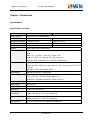
Specifications
Specifications for Printer
Model
X1
X1i
Printing method
Direct thermal & Thermal transfer
Resolution
203 DPI (8 dots/mm)
300 DPI (11.8 dots/mm)
Maximum print speed 6 IPS(152.4 mm/s)
4 IPS(101.6 mm/s)
Maximum print width
4.15″ (105.6 mm)
4.09″(104 mm)
Maximum print length 157.5″(4000mm)
78.7″(2000mm)
Memory
2 MB FLASH ROM, 2 MB SDRAM
Media
Roll-feed, die-cut, continuous, fan-fold, tags, tickets in plain paper or thermal
paper
Width:4.5″(114 mm) max.,0.8″(20 mm)min.
Supply roll: OD 5″(127 mm) max., ID 1″(25.4 mm) min.
Thickness: 0.08~0.20mm(0.003″~0.0078″), including liner
Ribbon
Wax, Wax/Resin, Resin
Ribbon roll: OD 2.75″(70 mm) max. with ID 1″(25.4 mm) core or ID 0.5″(12.7
mm) core
Max width: 110 mm; Max length: 300 M
Media sensor
Adjustable reflective & Transmissive
Bar Code Types
1D Barcode : Code 39,Code 93,Code 128,Codabar,EAN-8/13/128,Interleave
2 of 5,UCC-128,UPC A/E 2 and 5 add-on, etc.
2D Barcode : Data Matrix, MaxiCode, PDF417,QR, etc.
Interfaces
RS-232 serial, USB
Power rating*
24 VDC, 2.5 A
Weight
2.62 KGS
Dimensions
W208 x D310 x H195 mm
Operation
environment
Temperature: 32° F ~ +104° F (0° C ~ 40° C)
Relative humidity: 5% - 85% non condensing
Storage environment
Temperature: -40° F ~ +140° F (-40° C ~ 60° C)
Relative humidity: 5% - 85% non condensing
Optional items
Peeler kit, Internal 100/10 M Ethernet Interface card
6
8010001002
X Series User’s Manual
Chapter 1 Introduction
Specifications for Power Adapter
Input
AC 100~240 V, 47~63 Hz
Output
DC 24 V, 2.5 A
Environment
0° C ~ 40° C
Unpacking & Inspection
When unpacking the X Series Printer, make sure you save all packing materials.
Inspect the shipping carton(s) for possible shipping damage, if damage is discovered, notify the
shipping company to report the nature and extent of the damage.
Please check the items according to the Packing List. If there are any items missing, notify your
authorized reseller.
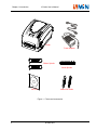
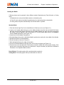
Packing List(see Figure 1):
1.
Printer……………………………...
1 pcs
2.
Power Adapter…………………….
1 pcs
3.
Ribbon Spindle……………………
2 pcs
4.
Media Spindle……………………..
1 pcs
5.
Media Roll Guide………………….
2 pcs
6.
CD Rom…………………………….
1 pcs
8010001002
7
Chapter 1 Introduction
X Series User’s Manual
Printer
Power Adapter
Ribbon Spindle
Media Spindle
CD Rom
Media Roll Guide
Figure 1:Printer and accessories
8
8010001002
X Series User’s Manual
Chapter 2 Installation & Operation
Chapter 2 Installation & Operation
Setting up
Before setting up the printer you should consider the following:
1. Make sure there is adequate space around the printer for loading consumables and proper ventilation.
2. Make sure the printer is close to the host so the interface cable is easily accessible at either end.
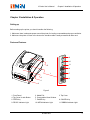
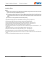
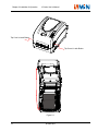
Parts and Features
9
10
11
5
8
7
1
3
6
4
2
Figure 2
1. Front Panel
4. Top Cover’s Latch Button
6. FEED Key
9. READY Indicator Light
2. Media Exit
5. Consumables View Window
7. PAUSE Key
10. MEDIA Indicator Light
8010001002
3. Top Cover
8. CANCEL Key
11. RIBBON Indicator Light
9
Chapter 2 Installation & Operation
X Series User’s Manual
1
6
3
2
11
10
7
6
8
8
9
5
4
7
12
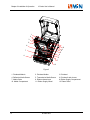
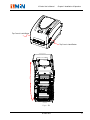
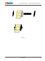
Figure 3
1. Printhead Module
4. Reflective Media Sensor
7. Media Guide
10. Media Compartment
10
2. Printhead Holder
5. Transmissive Media Sensor
8. Ribbon release lever
11. Ribbon Supply Wheel
8010001002
3. Printhead
6. Printhead Latch Levers
9. Ribbon Supply Compartment
12. Platen Roller
X Series User’s Manual
Chapter 2 Installation & Operation
6
1
2
3
5
4
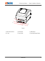
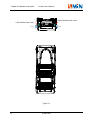
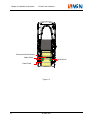
Figure 4
1. RS232 Serial Interface
4. DC Jack
2. DIP Switches
5. Power Switch
8010001002
3. USB Interface
6. Rear Media Supply Window
11
Chapter 2 Installation & Operation
X Series User’s Manual
Connecting the printer
Attaching Power
Caution:
(1) Use of the wrong power adapter could damage your printer. ZMIN Technologies assumes no
liability for any damage in such case. The rating for the printer is 24VDC.
(2) Make sure the AC voltage which you using is accorded with power adapter requirements.
(3)Never operate the printer and power adapter in an area where they can get wet. Serious
personal injury could result!
1. Make sure the printer’s power switch is in the OFF position.
2. Insert the AC power cord into the power adapter.
3. Insert the power adapter’s DC output plug into the DC Jack on the rear of the printer.
4. Plug the other end of the AC power cord into an appropriate AC electrical outlet.
Interface Connection
Notice:
Make sure the printer’s power switch is in the OFF position before connecting the interface
cable.
The X Series printers support a variety of interface options and configurations. These include: USB
interface, RS232 Serial.
1. Any interface can transmit data from the host. Preliminary communications settings are not required
since the printer will automatically detect which interface is active.
2. The default values of printer interface can be obtained from the self-test report. (See Chapter 2
Operation Basics – Advanced Functions - Self Test)
3. Cable configurations for serial (RS-232C) are shown in Appendix A of this guide.
4. Please take the following measures to reduce cable noise.
(1)Reduce the length of the data cable (keep the cable length under 1.83 meters / 6 feet) if required.
(2)Keep the data cable separate from power cords.
12
8010001002
X Series User’s Manual
Chapter 2 Installation & Operation
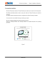
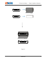
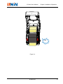
Consumables installation
The Direct Thermal print method or Thermal Transfer print method can be used in the X Series printer.
The Ribbon and Media should be load into the printer while the Thermal Transfer print method is
configured.
Only Media should be load while the printer is configured to the Direct Thermal print method.
You must use the correct media for the type of printing you require.
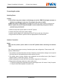
The route of loading the Ribbon and media as showed in Figure 5.
Please see “Loading the Ribbon” and “Loading the Media” for a complete description of the operating
procedures.
耗材安装示意图
Thermal Transfer Media Loading Instructions
碳带通道
Ribbon Route
标签通道1
Label Route(Alternative 1)
标签通道2
Label Route(Alternative 2)
Figure 5
8010001002
13
Chapter 2 Installation & Operation
X Series User’s Manual
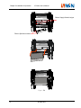
Loading the Ribbon
Notice:
(1) Make sure the ink side of your ribbon faces outwards. Always make sure the ink side of the
ribbon faces the media and NOT the printhead.
(2) The maximum width of the ribbon is 110mm. When using a ribbon roll with a width less than
110m, please place the ribbon roll in the middle of the Ribbon Spindle corresponding to the
scale.
(3) This section is not applicable to direct thermal printing.
1. Push the left and right Top Cover’s Latch Button to lift the top cover. (see Figure 5-1)
2. Pull the left and right Printhead Latch levers to release the Printhead Module.
3. Lift the Printhead Module to expose the Ribbon Supply Compartment. (see Figure 5-2)
4. Unwrap the ribbon roll pack and separate the ribbon roll and the core. (see Figure 5-3)
5. Slide the roll of Ribbon onto one of one Ribbon Spindle. (see Figure5-3)
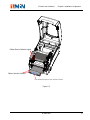
6. Load the Ribbon Spindle into the printer and route the ribbon through the Printhead Module. (see
Figure 5-4)
7. Slide the ribbon take up core onto the other Ribbon Spindle. (see Figure 5-3)
8. Wrap the end of the ribbon around the ribbon take up core. (see Figure5-5)
9. Load the ribbon take up core into the Ribbon rewind Compartment. (see Figure5-6)
10. Rotate the Ribbon rewind wheel on the left of the core to take up the loose ribbon and tighten the
ribbon.
11. Close the Printhead Module and press down until it locks into place.
14
8010001002
X Series User’s Manual
Chapter 2 Installation & Operation
Top Cover’s Latch Button
Top Cover’s Latch Button
Figure 5-1
8010001002
15
Chapter 2 Installation & Operation
X Series User’s Manual
Right Printhead Latch Lever
Left Printhead Latch Lever
Pull
Pull
Figure 5-2
16
8010001002
X Series User’s Manual
Chapter 2 Installation & Operation
Figure 5-3
8010001002
17
Chapter 2 Installation & Operation
X Series User’s Manual
Ribbon Supply Wheel’s bulges
Ribbon Spindle’s notches
Figure 5-4
18
8010001002
X Series User’s Manual
Chapter 2 Installation & Operation
Ribbon Rewind Wheel’s bugles
Ribbon Spindle’s notches
Use adhesive tape to stick with the ribbon
Figure 5-5
8010001002
19
Chapter 2 Installation & Operation
X Series User’s Manual
Rotate the Ribbon Rewind
Wheel, until the ribbon is
pulled tight across the
printhead.
Click
Figure 5-6
20
8010001002
X Series User’s Manual
Chapter 2 Installation & Operation
Loading the Media
X Series printers can be operated in three different modes: Standard mode, Peel-off mode, or Cutting
mode.
In Standard mode, each printed label remains on the backing liner.
In Peel-off mode, each printed label is peeled away from the backing liner automatically.
In Cutting mode, the printer automatically cuts the label after it is printed.
Standard Mode
1. Push the left and right Top Cover’s Latch Button to lift the top cover. (see Figure 6-1).
2. Load a roll of media (labels facing up) on the Media Spindle, then slide the two Media Roll Guides
with their smooth sides toward the media onto the Media Spindle from each end until snug against
the media. If you are placing a roll of media with a 3″ ID core, please slide the two Core Adapters
onto the Media Spindle first. (see Figure 6-2)
3. Insert them into the Media Compartment.
4. Corresponding to the scale on the Media Spindle, position the media roll in the middle of the Spindle.
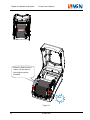
5. Release and lift the Printhead Module.
6. Route the media as shown in Figure 6-3.
7. Slide the Media Guide to the edge of the media.
8. Close the Printhead Module and press down until it locks into place (see Figure 6-4).
9. Close the top cover and press the ‘Feed’ button to feed the media and ensure proper tracking. If the
printer does not correctly sense the top of each label, it may be necessary to perform the Calibration
Procedure in the Operation Basics section.
Peel-off Mode: The loading guide will be provided with the peeler kit.
Cutting Mode: The loading guide will be provided with the cutter kit.
8010001002
21
Chapter 2 Installation & Operation
X Series User’s Manual
Top Cover’s Latch Button
Top Cover’s Latch Button
Figure 6-1
22
8010001002
X Series User’s Manual
Chapter 2 Installation & Operation
Figure 6-2
8010001002
23
Chapter 2 Installation & Operation
X Series User’s Manual
Transmissive Media Sensor
Media Guide
Media Guide
Platen Roller
Figure 6-3
24
8010001002
X Series User’s Manual
Chapter 2 Installation & Operation
Click
Figure 6-4
8010001002
25
Chapter 2 Installation & Operation
X Series User’s Manual
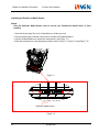
Adjusting the Position of Media Sensor
Notice:
Only the Reflective Media Sensor can’t be moved, the Transmissive Media Senor is fixed
installed.
1. Push the left and right Top Cover’s Latch Button to lift the top cover.
2. Pull the left and right Printhead Latch levers to release the Printhead Module.
3. Lift the Printhead Module to expose the media sensor. (see Figure 7-1)
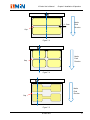
4. Slide the media sensor to the appropriate position (refer to Figure 7-3, Figure 7-4 and Figure 7-5).
Figure 7-1
Reflective Media Sensor
Figure 7-2
26
8010001002
X Series User’s Manual
Chapter 2 Installation & Operation
2 - 5mm
Media
Feed
Direction
Gap
Figure 7-3
Media
Feed
Direction
Gap
Figure 7-4
Media
Feed
Direction
Gap
Figure 7-5
8010001002
27
Chapter 2 Installation & Operation
X Series User’s Manual
Operation
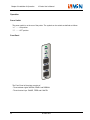
Power Switch
The power switch is on the rear of the printer. The symbols on the switch are defined as follows:
“━” —— ON position.
“〇” —— OFF position.
Front Panel
The Front Panel of the printer consists of:
- Three Indicator Lights: MEDIA, READY and RIBBON
- Three function Keys: PAUSE, FEED and CANCEL
28
8010001002
X Series User’s Manual
Chapter 2 Installation & Operation
Indicator Lights
The three Lights indicate the status of the printer (please refer to Chapter4 for error indications)
READY
- On: Indicates the printer is in the normal state;
- Flashing: Indicates the printer is in the ‘PAUSE’ state.
MEDIA
- On: Indicates the printer is in the normal state;
- Flashing simultaneously with READY: Running out of media;
RIBBON
- On: Indicates thermal transfer printing;
- Off: Direct thermal printing (no ribbon requirements);
- Flashing simultaneously with READY: Running out of ribbon.
The Indicator lights combinations indicate the status of the printer as follows:
:The Indicator lights is Off
:The Indicator lights is On
:The Indicator lights is Flashing
Status
Indication
In Thermal Transfer Mode:
Printer is in the normal state
In Direct Thermal Mode:
Printer is in the normal state
In Thermal Transfer Mode:
Printing pause operation;
Error printing data is found;
In Direct Thermal Mode:
Printing pause operation;
Error printing data is found;
8010001002
29
Chapter 2 Installation & Operation
X Series User’s Manual
In Thermal Transfer Mode: Media Out
In Direct Thermal Mode: Media Out
In Thermal Transfer Mode: Ribbon is Out
Enter Advance Function Mode
Keys
The three keys have different functions based on the mode of the operation is performed.
Key Name
FEED
30
Basic Functions
Advanced Functions
(see Advanced Functions below)
Feed one label
Media Sensor Calibration
PAUSE
- Press once to pause current
print job
- Press a second time to resume
printing
Self-test:
The Printer performs a self-test and
prints out a configuration report
CANCEL
- Cancel current batch of labels
- Forces the printer to continue
working after an error has
been corrected
Reset:
Resets the printer to Factory Default
Settings
8010001002
X Series User’s Manual
Chapter 2 Installation & Operation
Advanced Functions
Media Sensor Calibration
It is necessary to accomplish Media Sensor Calibration after a new roll of media has been loaded.
1. Press and hold the FEED key for about 4 seconds.
2. The printer will feed approximately 200mm of media;
3. The three indicators stop flashing and remain lit. The printer is back to a normal state.
Self Test
1. Press and hold the PAUSE key for about 4 seconds;
2. The printer will print out a configuration report and the three indicators will stop blinking and remain lit.
The printer is back to a normal state.
3. The following information will be printed on the self-test report:
- Printer’s model and part number.
- Firmware version
- Hardware configuration and status
- DIP switch settings
- Label parameters
- Font list
Reset – Reset the Printer to the Factory Default Settings
Following the steps listed below allows you to reset the printer to the factory default settings.
1. Press and hold the CANCEL key for 4 seconds, the three lamps will flash simultaneously (the printer
will return to normal state automatically if no operations are performed within 4 seconds);
2. Release and press the CANCEL key again;
3. The three indicators stop flashing and remain lit. The printer is now in its normal state.
The following parameters have automatically been reset:
- Label
- Print darkness
- Speed
- Others
Note: The printed label count and printed length may not be reset.
8010001002
31
Chapter 2 Installation & Operation
X Series User’s Manual
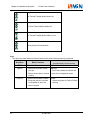
ON
OFF
DIP Switches at the rear of the printer
1
2
3
4
5
6
7
8
Note: Please turn off the printer before setting the DIP switches.
DIP Bit
Functions
1
ON: Direct thermal print mode
OFF: Thermal transfer print mode
Printing method setting
Default: OFF
2
ON: Tear off position
OFF: Edge of next label
Stop position setting
Default: OFF
3
ON: Cutter is installed
OFF: Cutter is not installed
Cutter setting
Default: OFF
4
ON: Peeler is installed
OFF: Peeler is not installed
Peeler settings
Default: OFF
5
ON: Transmissive Media Sensor
OFF: Reflective Media Sensor
Media Sensor type setting
Default:OFF
6
ON: Enable IP setting
OFF: Disable IP setting
IP address setup
Default: OFF
7
8
7
OFF
ON
OFF
ON
8
OFF
OFF
ON
ON
Remarks
– 9600,n,8,1
–19200,n,8,1
– 38400,n,8,1
– 57600,n,8,1
RS232 Serial Port baud rate setting
Default: OFF | OFF
Windows Driver and PosLabel Software
The printer driver supports Windows 7/Vista/2003/XP/2000/NT operating systems. Each X Series
printer comes with powerful barcode label edit software. Both the Windows driver and software are
32
8010001002
X Series User’s Manual
Chapter 2 Installation & Operation
available on the manufacturer’s CD-ROM shipped with the product. If you do not have the
manufacturer’s CD-ROM or wish to upgrade your current software, it is available for download from:
www.zmin.com.cn.
Note: If you need to update the driver, please remove any old versions of the driver before
continuing.
8010001002
33
Chapter 3 Maintenance
X Series User’s Manual
Chapter 3 Maintenance
Caution:
1. Make sure the printer is turned OFF before performing any maintenance operations.
2. The printhead becomes hot while printing, be careful when performing maintenance on the
printhead.
3. Use only the cleaning agents indicated. ZMIN Technologies will not be responsible for
damage caused by any other cleaning materials used on the printer.
4. Absolute alcohol is a solvent containing no more than one percent water. Absolute alcohol is
a flammable solvent; always take the proper precautions when using this solvent.
Cleaning the Printhead
The printhead is easily damaged due to its precision construction. A printhead damaged by misuse is
not covered under the terms of the warranty. To ensure longevity of the printhead, please note the
following:
1. Always use proper cleaning materials and techniques to clean the printhead. Never use hard
materials for scraping the printhead.
2. Always use high-quality consumables. When the TPH module is closed, pressure is placed directly
on the TPH; dirt such as paper scraps, sand, dust and glue can scrape or damage the printhead. The
TPH is also easily damaged by static electricity, which may be generated by poor quality ribbons.
3. After every roll of ribbon or every three rolls of media, the printhead should be cleaned with absolute
alcohol.
a. Turn off the printer and open the cover.
b. Release and lift the Printhead Module.
c. Remove the ribbon (if applicable).
d. Using a Cotton Swab dipped in absolute alcohol, rub the Swab along the printhead.
Cleaning the Platen Roller
Debris or dirt accumulated on the platen roller should be cleaned after every three rolls of media.
a. Turn off the printer and open the cover.
b. Release and lift the Printhead Module.
c. Rotate the platen roller and clean it thoroughly with absolute alcohol and a cotton swab.
34
8010001002
X Series User’s Manual
Chapter 3 Maintenance
Cleaning the Printer Interior
With a brush or a vacuum cleaner, as needed.
8010001002
35
Chapter 4 Troubleshooting
X Series User’s Manual
Chapter 4 Troubleshooting
Occasionally situations occur that require some troubleshooting. Possible issues and potential
solutions are listed in this section. While not every situation is addressed, you may find some of
these tips useful.
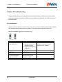
Error Indications
Typically, when the printer is not functioning, one or two of the three indicator lights will begin flashing.
The possible situations addressed by the status of the three indicator lights are listed below.
READY and MEDIA lights flash simultaneously
or
36
Possible Cause
Recommended Solutions
Remarks
Cannot detect the media
gap or black line
(1) Check the media path
(2) Check the position of
the media sensor
(3) Perform media sensor
calibration
If you are using continuous media,
be sure you have the correct
settings in your software
Media run out
Load a roll of media
Media jam
The Media Roll Guides are
not firmly positioned
against the media
Media sensor error
Clear the jam
Adjust the Media Roll
Guides to firmly press
against the media
Service media sensor
8010001002
X Series User’s Manual
Chapter 4 Troubleshooting
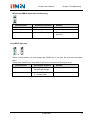
READY and RIBBON lights flash simultaneously
Possible Cause
Recommend Solutions
Run out of ribbon
Load a roll ribbon
Ribbon jam
Clear the jam
Ribbon Sensor error
Service Ribbon Sensor
Remarks
To be serviced only by qualified
personnel
Only READY light flash
or
Please confirm whether you have pressed the PAUSE key or not, force the print enter print pause
state?
Please press PAUSE key, if the problem is still exist, it’s may be the following list cause:
Possible Cause
Recommend Solutions
Serial I/O error
Check DIP switches for
the band rate settings
Memory overflow
a. Restart the printer
b. Perform Reset
8010001002
Remarks
37
Chapter 4 Troubleshooting
X Series User’s Manual
Miscellaneous
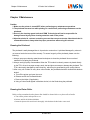
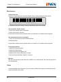
Vertical blank lines
Continuous vertical blank lines in printout indicate a dirty or faulty printhead as shown below:
SHENZHEN ZMIN TECHNOLOGIES CO.,LTD.
If the problem cannot be solved by cleaning the printhead, replace the printhead.
The host shows ‘Printer Timeout’
1. Check if the interface cable is connected.
2. Check if the printer is turned on.
If the situation remains unsolved, please contact your reseller or our customer service engineer.
The data has been sent, but not printing
1. Verify you have chosen the correct Windows printer.
2. Reset the printer.
If the situation remains unsolved, please contact your reseller or our customer service engineer.
Print quality problems
1. Adjust Print Darkness setting.
2. Adjust Print Speed setting.
3. Clean the printhead and platen roller.
4. Make sure the correct media/ribbon is loaded.
5. Use only high-quality Media, replace if necessary.
Recovery
After the corrective action is taken press the CANCEL key to clear the alarm, the printer will get back to
work automatically.
Others
Contact a qualified Service Engineer from your reseller or ZMIN Technologies for troubles that persist
or are not covered in this section.
38
8010001002
X Series User’s Manual
Appendix A: Interface Specifications
Appendix A: Interface Specifications
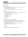
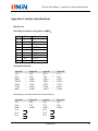
RS232 Serial
The RS232 connector on the printer is a DB9F:
Pin
Direction
Definition
1
/
/
2
Out
TX
3
In
RX
4
In
DTR
5
-
Ground
6
Out
DSR
7
In
CTS
8
Out
RTS
9
/
/
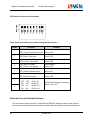
Connection with host:
Host 25S
TX 2
RX 3
DSR 6
DTR 20
RTS 4
CTS 5
GND 7
………
………
………
………
………
………
………
Printer 9P
3 RX
2 TX
6 DSR
4 DTR
7 CTS
8 RTS
5 GND
Host 9S
RX 2
TX 3
DTR 4
DSR 6
RTS 7
CTS 8
GND 5
………
………
………
………
………
………
………
Printer 9P
2 TX
3 RX
4 DTR
6 DSR
7 CTS
8 RTS
5 GND
Alternately you can just connect the 3 wires as follows:
Host 25S
Printer 9P
TX 2
……… 3 RX
RX 3
……… 2 TX
GND 7
……… 5 GND
pin 4
pin 5
pin 6
Host 9S
Printer 9P
RX 2
……… 2 TX
TX 3
……… 3 RX
GND 5 ……… 5 GND
pin 4
pin 6
pin 7
8010001002
39
Appendix A: Interface Specifications
X Series User’s Manual
pin 20
pin 8
Baud rate: 9600, 19200, 38400, 57600
(Baud Rate set by DIP switches 7–8)
Data format: always 8 data bits, 1 start bit and 1 stop bit.
Parity : always non parity.
Flow control: RTS/CTS (Hardware flow control).
If you are using software or drivers under the Windows environment, the flow control must be set to
“hardware”
Parallel (Centronics)
The parallel port is a standard 36-pin Centronics interface. Its pin assignments are as follows:
Pin Direction Definition
Pin
Direction Definition
1
In
/STROBE
13
Out
2
In
Data 1
14,15
3
In
Data 2
16
-
Ground
4
In
Data 3
17
-
Ground
5
In
Data 4
18
NC
6
In
Data 5
19~3 0
Ground
7
In
Data 6
31
NC
8
In
Data 7
32
9
In
Data 8
33~3 6
10
Out
/ACK
11
Out
BUSY
12
Out
PE
SELECT
NC
Out
/Fault
NC
Note: Never send data from 2 ports at the same time. Data cannot be sent to more than one port
simultaneously or data corruption and print errors may occur.
40
8010001002
X Series User’s Manual
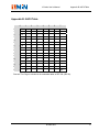
Appendix B: ASCII Table
Appendix B: ASCII Table
0
3
4
5
6
7
0
@
P
`
p
!
1
A
Q
a
q
“
2
B
R
b
r
3
XOFF #
3
C
S
c
s
4
$
4
D
T
d
t
%
5
E
U
e
u
0
NUL
1
SOH
2
STX
5
1
XON
NAK
2
6
ACK
&
6
F
V
f
v
7
BEL
‘
7
G
W
g
w
8
BS
(
8
H
X
h
x
)
9
I
Y
i
y
*
:
J
Z
j
z
+
;
K
[
k
{
9
A
LF
B
ESC
C
FF
,
<
L
\
l
|
D
CR
-
=
M
]
m
}
E
SO
RS
.
>
N
^
n
~
F
SI
US
/
?
O
_
o
DEL
Remark: The € sign is included in the embedded table at DEC128 (HEX 80).
8010001002
41
SHENZHEN ZMIN TECHNOLOGIES CO.,LTD.
*8010001002*