1
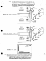
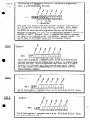
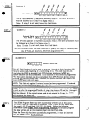
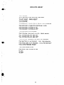
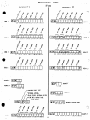
SECUR-fone
Hook-up & lnstaI!ation
Fire BuralwyInstruments,
_
Inc.
50 EngineersRoad,Hauppauge.New York 11788
NEW YORK
(516) 582.6161 =
OUY Of SlAlf
(800) 645-5430
REV B - FEB ‘86
.i
.
/I’
.
>
L
a
.
.
SE&R-fone
l
* !
’
.-I..>>.J-->.
.
The Secur-fone
model SF200 is designed to operate exclusively
with the XL I2 I8 and XL 1219
Control
Panels.
Incorporating
the SF200 will enable all on and off-premises
telephones
(assuming they are touchtone)
to be used as keypads.
1218F and 1219F keypads may be,
used in conjunction
with the SF200 if desired, or the SF200 can be used by itself.
If the
SF200 is used as a standalone,
(with no keypads on site) remote red led and sonalert
terminals have been provided to indicate
arm status and all sonalert activity.
To access the
SFZOO, specific keys must be depressed in specific order via the telephone
pad. The
Secur-fone will respond clearly with English language messages concerning
the system’s
status.
The SF200 English language messages must be programmed (hand tailored)
into a
FBI model FlO2 prom chip, as per the programag
section of this manual.
The SF200
can also be progrqmmed to allow off-premises access via touchtone telephones. Lastly,
that can be used to
there are 3 auxiliary relays which contain Form C Dry Contacts,
activate
on-premises
tion instruction
will
panels first,
OPERATION
lites, air conditioners,
etc.
explain terminal
connections
via the SF200 System.,
This installaof the SF200 to the 1218 and 1219 control
then proceed with the prom programming.
THE ACTUAL
SECUR-FONE
WlLr, BE ,EXPLAINED
IN THE SF200 END USER MANUAL.
Note:
The SF200 is designed to work exclusively with touchtone phones. Therefore,
rotary phones can-be on site with the SFZOO.
_
__
. --T
HO~KUP/WRING..
_
SF200
’ 1218
1219
Terminals
Terminals
Description
Terminals _
1
2
3
1
2
3
1 .
2
3
4
5
6
7
8
9
10
11
1213
l ;
l
5
8
9
37
27
29
SF200 detects fire trouble on 1219 here
SF200 detects low bat on 1219 here
I SF200 detects AC loss here
32
i SF200 detects fire alarm on 1219 here
1 SF200 detects burglary alarm here
2;
* Form C dry contacts on relay
Common
Nor mall y closed
Number 3. Toggled by #3
I
Normally open
at telephone
Common
Jc Form C dry contacts on relay
Normally closed
number 2. Toggled by /12
1
Normally oben
at telephone
JC Form C dry contacts on relay
Common
Normally closed
Number 1. Toggled by I1
1
at telephone
Normally open
A remote red led may be wired to these terminals to ‘display
arm sfatus of the svstem.
A remote Mallory Model 515 Sooalert may be wired to these terminals to
annunciate on entry time, ringback, day loop, chime feature, etc.
A remote 8~ 10 watt speaker may be wired here ta listen to SF200
l .
I
l
14
1516
17
18
19
20(-J
21(+)
21(+)
22(-l
23(+)
_,
Keypad Data Terminals.
The SF200 reads loop data and instructs
the Control Panel via these terminals
4
;
-NO
;
I
= These terminals
do not have to be connected
Jt CONTACTS
RATED
when the SF200 is wired
AT 250 VAC,
1
60 VDC,
3 AMP.
ta X11218.
NOTE:
.
:*
When the Convenience
Switch
on the SF200 box is depressed,
the
home phones will be connected
directly
to the outside
lines, which
enables
the customer
to prevent
access
to SECUR-fone
by on-premises telephones.
However,
external
access
to SECUR-fone
can still
be accomplished.
Furthermore,
the Control
Panel $J
seize the
This switch
sho$d,?ormally
be
home phones if a violation
occurs.
in the OUT position.
%
,
w-200
PtlONE
LINE:
TERMINALS
m---------mPHONE
LINE
HOOKUP
SF200 TO XL1218
TERMINALS:
REY
SF-200
PHONE
LINE
TERMlNALS
-e-w-------PHONE
LINE
HOOKUP
SF200 TO XL1219
3:s
PHONE
LINE
,
\
GREEN
RED
SECUR-forte
F.C.C. Regkvation
NOTE:
.
P.C.
Board.
No. AE398E-695~AL-E
for FIRE BURCLARY
CORD
INSTRUMENTS
MODEL SF-200
Whenever the kcur-fone
is disarmed, it will automaticall
deliver a status
on disarm, depress [*I f l ] twice.
If the
message. If status is not reporrcd
m&age
“The Central was not called.
Press Reset” is generated,
depress
[I] [O] to reset. Depress [*I [+I AGAIN to OBTAIN Final System Status.
At this point any other syrrem functions
desired may be performed.
/*’
SF200
I.1
a-
PROM
PROGRAM
A Prom chip model F102 (DM74S387N,
or 635140N)
must be programmed
with an FBI 110 or
of the Prom must be
l IOC programmer
for proper operation
of the SFZOO. Two quadrants
programmed.
Either quadrants
one and two or quadrants
three and four may be used. The
condition
of the R58 resistor jumper in the SF200 will dictate
which two quadrants
the SF200
will read.
The chart below depicts
R58 jumper setting
for the desired quadrants
used.
.
)
The main body of programming
that is required
for the SF200 is the ENGLISH
LANGUAGE
words that will be reported
(said) when any of the zones of the Control
Panel are read by
the SF200. In other words, the zones of the Control
Panel must be Named or hand tailored.
Example:
Zone 1 = Front door
Zone 2 = Kitchen
Zone 3 = Basement
Furthermore,
the three auxiliary
relays must also be named.
Example:
Relay 1 = Air conditioner
Relay 2 = Front yard lights
Relay 3 = Relay 3
(THIS INSTRUCTION
SF200 PROGRAM
Quadrant
c
STEP
BOOKLET
IS DESIGNED
TO FACILITATE
WRITING
OUT THE
SHEET WHICH IS LOCATED
AT THE END OF THIS MANUAL)
1
A.
The first location
of the OP Field, Quad 1, marked Ll must contain
a digit
from the chart below which represents
the TYPE of zone that zone 1 has
been programmed
in the XL1218 or XL12!9
Control
Panel:
(example:
24 HR Trouble
Zone, 24 HR Alarm
Zone, Controlled
Burglary
Zone)
Select the appropriate
digit from.chart
below:
NOTE:
If zones are programmed
as 24 HR. alarm zones, the SF200
will not report the zone words, therefore
locations LZ-Lll
should
be programmed
[FJ1
Digit
I
Zone
1
24 Hr Alarm
24 Hr Trouble
Controlled
Delay,
Instant,or
Interior
0
r
I
I
3
Type
I
The second through
eleventh
location
marked L2-Ll l
of this field represent
the
5 total words that can be programmed
to NAME or Hand Tailor zone 1. Locations L2 and L3 represent
the first word, L4 and L5 the second word, etc.
Each word desired has a 2 digit Hexidecimal
number
that corresponds
tc that
word.
The two digit numbers and corresponding
woids can be found in the
PROGRAMMABLE
LIBRARY,
page 10 . Write in the appropriate
two digit numbers that represent
the words desrrezor
zone 1 in this OP field.
If zone 1
requires
less than five words, leave the corresponding
locations
for the unused
words blank.
cont’d. pg. 4
3
_
1
The following
is an example
zone 1 is a controlled
delay,
* STEP’ A
-
cbnt’d.
of how the OP field
front door.
should
be
programmedif ,
&
1
Y
STEP
Since zone 1 is a burglary
zone, there are many conditions
it could actually
be in during
many instances
of daily operation.
(example:
Alarm,
Bypass,
Trouble
while the system
is disarmed,
etc.)
When status is requested
from
the SF200, the words that were programmed
here into the OP field will
PRECEDE the PHRASES
that apply from the DEDICATED
LIBRARY of Terms for the
condition
of zone 1. (example:
Zone 1 is bypassed;
then status is requested.
The SF200 will say “FRONT
DOOR
IS BYPASSED”.
“FRONT
DOOR” is from
this OP field, “IS BYPASSED”
comes from the Dedicated
Library.)
Zone 1 has been successfully
programmed.
B
I ---.w1 P
ZONE 2
II
L
-
I I-l I I I I I I II
L2
1)
Lb
15
L6
L7
18
L9l1OLIl
The 1P field of Quadrant
1‘ represents
zone
The same procedure
must be followed
here,
Select an appropriate
sents the tone type.
Location
L2-Ll I represent
the 5 total words
the 2 digit numbers
that CORRESPOND
TO
PROGRAMMABLE
LIBRARY.
2 on the XL 1218 and XL1219.
as Step A. Ll location
repredigit
from Chart A rn Step A.
to Name zone 2. Select
the words desired from the
STEP C
ZONE3
1 1 1 1 1 1 1 1 1 1J
[2lpI‘
Ll
12
L)
I>
L4
The 2P field quadrant
! represents
the same Drocedure
as Step A.
STEP
D
Quadrant
16
zone
17
LU L9tloLll
3 on the XL1218
and XL1219.
Follow
1
I
11
I I I I I I I I I II
12
The 3P field quadrant
1 represents
1 the same procedure
as Step A.
Cf
1rL5
zone
16
17
4 of the
II
I9LlOL11
XL1218
and XL1219.
Follow
/-coNTRol
.
.-*
Quadrant
STEk’E
1
PAW
TYPE
'EXTERNAL ACCESS,
RELAY STAIUS, EXKRNAL tXlTffl
WlPUl TYPE
FIRE BELL
//
[A[Cl
/--RING
1
'1
1
COUNT
]
THE FIRST LOCATION of this AC field marked Ll informs the SF200 what
Control Panel is being used. Select an appropriate digit from the following
chart for this Ll location.
’ Digit
Control
0
2
Access:
Option Two - Automatic
/
XL1218
XL1219
THE SECOND LOCATION of this AC field
the following
three options:
Option One - External
Panel Type
marked
._
’
L2 is used to determine
If External Access is programmed, all system functions
can be accomplished from off-premises touch-tone
telephones, including arm/b’isarm and code reprogramming.
Relay Status:
If this option is programmed, whenever system
status is requested from the SF200, it -will inelude the status of all auxiliary relays. If
“Automatic Relay Status” is not selected,
relay status must be initiated%kually
by
depressing [#I then 181.
Option Three - External Exiter: This option has been included in the SECUR-fone and
should be used only if the main control instrument (1218 or 1219) has been designed to
include at letit one controlled INTERIOR zone. The purpose of this option is
to enable the end user to call from ‘an off-premise telephone, arm his system
without excluding the interior zone.
When External Exiter is programmed and the system is armed from an OFFPREMISES TELEPHONT,
auxiliary relay 3 will automatically actiyate momenRelay 3 closed circuit contacts (SECUR-fone terminals 11 andr
tarily.
MUST be wired in series with the Control Panel Delay Loop. a
The momentary activation of relay 3, after arming, will simulate exit through the delay
zone causing the control panel to include the interior zone. Relay 3 will not activate
momentarily when the system is armed from on-premises telephones.
Lastly, when this option is selected, relay 3 can no longer be utilized as an auxiliary
relay circuit.
NOTE: If this option is not selected, relay three will operate the same as auxiliary
relay
1 and 2. Select the digit from the following chart which corresponds to all options desired.
’
DIGIT
EXTERNAL
ACCESS
AUTOMATlC
RELAY STATUS
0
NO
YES
3
YES
YES
YES
YES
NO
7
8
B
F
‘,
NO
YES
YES
EXTERNAL
NO
YES
NO
NO
NO
YES
EXlTER
con t’d. pg.6
G-EP.
E
THE THIRD LOCATION marked 13 informs the SF200 what type of Fire
Bell output has been programmed in the XL1218 or XL1219 Control Panels.
When the SF200 system is used in conjunction with the XL1218 the XL1218
PANEL MUST be programmed PULSING BURG BELL OUTPUT for the Fire
zone. Therefore, this location 13 in the SF200 must be programmed with
Digit [Cl when used with the X11218. The XL1219 can be programmed for
EliHER PULSING BURGLARY BELL OUTPUT FOR THE FIRE ZONE OR
STEADY FIRE HORN OUTPUT. Therefore, select a digit from the following
chart which informs the SF200 what type
- . of Fire output is being used on
the respective Control Panels.
,. cont.‘d.
0
I
DIGIT
4
C
I
Note:
1
Control
Panel Fire Output
Pulsing Burg Bell output
Steady Fire Horn output
?
’
I
for Fire
If the SF200 is used with the X11218, this 13 location MUST be
the XL1218 MUST be programmed
programmed
Digit [4],
PULSING BURG BELL OUTPUT for the Fire zone in Quad 2, 3P field,
11 location on ITS Prom.
I
THE FOURTH LOCATION OF THE AC FIELD marked L4 determines the number of rings
telephones.
required before the SF200 will pick up, when accessed from OFF-premises
‘Select the digit desired from the following
chart.
NOTE:
If eiternal
access has not been selected,
DIGIT
program
NUMBER OF RINGS
I
1
1
2
2
:
5
this location
“F”.
-35’
..
I
5
6
6
7
7
8
8
9
9
A
i
10
B
i
11
c
12
D
13
E
14
F
No External
’
Access
‘...
3
.
STEP
F
Quadrant
1
/
11
--
--
.-.
11111111111
12
1)
1015
16
I71B191I0~I1
The AL field of quadrant
1 represents
zone 5 on the XL 12 19. The same pro
cedure must be followed
here as Step A to Name (Hand Tailor)
zone 5 of the
Select an appropriate
digit
from
X11219.
Li represents
the zone type.
Chart A in Step A. Locations
L2-111 represent
the 5 total words to name
the words desired from
zone 5. Select the 2 digit numbers that represent
the PROGRAMMABLE
LIBRARY.
Note:
STEP
If the SF200 system is being used in conjunction
AL field MUST be left blank.
with
6
11
12
1)
1015
16
17
18
this
19Ll0111
The OP field quadrant
2 represents
zone 6 of the X11219.
procedure
as step F to Name (Hand Tailor)
zone 6.
Note:
If the SF200 system is being
field MUST be left blank.
used in conjunction
H
Quadrant
8
2
3
Aux.
Relay
1
i1
Follow
with
8
9
g8$
--
i
X11218,
G
Zone
STEP
the
the same
an X11218,
8
$
---
I I I I I I I I I IF1
12
1)
LbL>
16
17
La
19ClOlll
The IP field quadrant
2 is used to Name (Hand Tailor)
auxiliary
relay 81.
Locations
11-110
represent
the 5 total words.
Select the 2 digit numbers
that correspond
to the words desired from the PROGRAMMABLE
LIBRARY.
The 111 location
must be left blank.
Note:
If reldy 1 is not used, leave this field blank.
this
-\ . STiP
I
Quadrant
2
--w--v
Aux.
Relay
PI I I I 1 I I I I I IF
2
Ll
12
L)
rrrs
&6
LILOL9lIOL.II
The 2P field quadrant
2 represents
auxiliary
relay
must be followed
as in Step H to Name relay 2.
Note:
If relay
2 is not used,
leave
this
field
2. The same procedure
blank.
L
STEP
J
Quadrant
2
External Exiter
Aux. Relay 3
LI
L2
The 3P field quadrant
2 represents
be followed
as in Step H to Name
Note:
NOT,E:lf
h=TEP
K
If relay
,e
$
-----
3 is not used,
I)
1r13
auxiliary
relay 3.
leave
”
$
9
I I I I I I I I IF1
this
External
Exiter has been selected
this 3P Field, all locations,
MUST
QUADRANT
Q
~617lnL9IIot1I
relay
field
3.The
same procedure
must
blank.
in Qttad 1, AC Field,
be programmed
“F”.
L2 Location,
then
2
[AfCl
1 1 1 ]
L1
LZ
LJ
SECURITY
ACCESS CODfI
LC
This AC Field Quadrant 2 can be used to program 1 through 4 digits (numbers O-9)
Security access code, beginning in 11 and ending in 14. This code must be utilized when the SF200 is accessed from OFF-Premises
telephones,
be=
any
system functions can be accomplished.
If all locations in this field are programmed
“F”i then system functions can be accomplished
from OFF-Premises
phones without
entering this security access code. However,
all system functions
that require the
main con=
panel code still apply.
NOTE: This field only applies if external
access has been programmed.
access has not been selected. Drotzram Ll - 14 “F”.
If external
I
NOTE: If security access code is programmed,
the customer must wait for the SF200
to pick up after the programmed number of rings, then depress [*I and his 1 through 4
digit security access code. Then proceed with desired functions
as explained
in the
End User Manual. If the correct access code is not entered in 3 tries. th- cc3nn
I
will -terminate the phone call.
STEP L
e
The SF200 Program Sheet has been successfully
written
All other fields not mentioned
in quadrant
1 and 2 must
Utilize
(i.e. quad 1 AF, FF and Quad 2 AF, FF, AL fields).
information
called Proper Prom Programming
Procedure.
the data written
out on the program
sheet into the Prom
Once the Prom chip has been successfully
into the SF200 socket, BLUE DOT up.
programmed,
out at this point.
be left blank also.
the following
to actually
program
chip.
it must
be inserted
.
.
PROPER
PROM
PROGRAMMING
PROCEDURE
STEP
A
Power up 110 or I IOC. The Prom MUST NOT
Insertion
of the Prom will be the last stepzor
STEP
B
Select the desired Quadrant
to program.
rant (ori of the chip) at a time.
STEP
C
Depress [ENTER]
momentarily,
then [0] while the programmer
socket is empty.
Depressing
[ENTER and 0] loads the present
contents
of the socket into memory.
In the case of an empty socket, memory
is loaded with Blanks or [F’s].
A Blank
The only time the [F] -Button must actually
be deand an [F] are the same thing.
pressed is if one specific
location
in a Field must be jumped over to get to another
location
to enter a number.
Trailing
[F’s] at the end of a fiemeed
not be depressed
as long as their locations
are Blank.
STEP
D
Punch in desired information
for OP field through
AL field in this Quadrant.
Movement from OP to the next field and so on, can be accomplished
by depressing
[ENTER]
then [Yl. At the bottom
left corner of the programmer
resides a chart which represents the field names, descriptions
and most important,
the field numbers.
Jumps can
be accomplished
from one field to another
by depressing
[ENTER],
then the respective
field number desired.
Example:
To jump from OP field to AC field, depress [ENTER]
then [7]. This variable
jumping
will become useful for duplicating
master chips.
STEP
E
After
completing
data entry into all desired
fields,
the Prom may be inserted
into
the programmer
socket.
The Blue Painted
dot must be situated
down.
The Prom
must be pushed all the way in. The programmer
does not care what field you are
in when you program.
Depress the [Program]
Buttonmomentarily,
[Finish]
should
be disolaved.
STEP
F
The present quadrant
has been successfully
programmed.
To program
additional quadrants,
the Prom must be removed,
select the desired quadrant
and
repeat steps C-F.
Summary:
The
be in the Programmer
at this time.
to depressing
the Program
Button.
110 and IIOC
will
program
one quad-
‘,
IF]:
The (F] B utton does not display anything
when depressed,
however
it jumps.
from one location
to the next.
The only time the [F] Button
must actually
be
depressed is when a jump must be made over one location
to get to another
location where a number must be entered.
Trailing
F’s need not be depressed as long
as their locations
are blank.
[Enter],
[Enter],
[Enter]
[Enter]
then [0] with
then [OJ with
then
then
[Y]:
field
socket empty:
Prom in socket:
Loads F’s in selected
quadrant.
Loads memory
with present data that resides in the quadrant
selected.
1ncrements
fields from OP to AL back to OP again.
number:
Jumps from one field to another
as designated
by respective
field number.
9
PROGRAMMABLE
00
NOI
02
803
NO4
HO5
/06
07
08
A
AC
AIR CONDITIONER
ALARM
ALL
AND
ARE
AREA
ATTIC
27
/28
29
ZA
FLOW
FOUR
FREEZER
FRONT
2B GARAGE
2C GUEST
2D HALL
02E HAVE
2F HIGH
09
Q9
CR
/oC
400
OE
OF
10
-11
.
-12
-13
~14
15
416
CALL
CENTRAL
CHECKED
CLOSET
COMPUTER
-17
-18
19
1A
1B
1C
ID
DDD
DELAYS
DEN
DETECTOR
DINING
DOOR
DOWN
1E
IF
20
21
EAST
EIGHT
ENTRANCE
EXIT
22
23
R4
25
26
a
.
BACK
BASEMENT
BATH
BATTERY
BE
BEDROOM
BOILER
BURGLAR
BYPASSED
FACTORY
FAN
FIRE
FIVE
FLOOR
NOTE:
30
,31
32
33
/34
IMMEDIATELY
IN
INSTANT
INTERIOR
IS
35
KITCHEN
36
37
38
39
3A
3B
LAUNDRY
LEAVE
LEFT
LIGHTS
LIVING
LOW
3C MASTER
3D MEDICAL
,3E MUST
LIBRARY
.
4C
c4D
4E
PRESSURE
PROGRAM
PROTECTED
-4F
50
51
-52
53
,
READY
RECEIVING
RELAY
RESET .
.PIGHT
.
5’5’ :ROOM
56
~57
~58
59
SAFE
SECURITY
SERVICE
SEVEN
5~
5c
5D
5E
5F
/60
61
62
SIDE
SIX
SKYLIGHT
SLIDING
SMOKE
SOUND
SOUTH
ssssss
63
64
.- 65
STAIRS
STOCK
SYSTEM
66
-67
68
,69
6A
TEMPERATURE
THEE
THREE
TROUBLE
TWO
6B
UP
3F
40
441
NINE
NORTH
NOT
6C
VIOLATED
-43
44
~45
46
47
OF~F
OFFICE
ON
ONE
OUT
6D
-6E
6F
70
71
72
WALL
WAS
WATER
WERE
WEST
WINDOW
~4%
49
4A
-4B
PANIC
PERIMETER
POLICE
PRESS
-73
YOU
DDD is to indicate
past tense of a word.
SSSS is to pluralize
a word.
10
-7j
74
75
ZERO
ZONE
7
-
3
-.
.
. .
-
.* .
*
.
DEDICATED
LIBRARY
.
“IS IN AL ARM”
,
,
“IS IN TROUBLE
AND MUST BE CHECKED”
“IS NOT RESET.
PRESS RESET”
“IS BY PASSED”
“THE SECURITY
COMPUTER
IS READY
FOR PROGRAM”
“THE SECURITY
COMPUTER
PROGRAM
IS OFF”
“THE SECURITY
SYSTEM
IS ON”
“THE SECURITY
SYSTEM
IS OFF”
“THE CENTRAL
WAS CALLED”
“THE CENTRAL
WAS NOT CALLED.
“ALL
SYSTEM DELAYS
ARE ON”
“ALL
SYSTEM DELAYS
ARE OFF’
“THE AC IS IN TROUBLE
e-
“THE BATTERY
AND MUST BE CHECKED”
IS IN TROUBLE.
“THE FIRE ZONE IS IN TROUBLE.
“YOU HAVE PRESSED PANIC”
“THE FIRE SOUND IS ON”
“THE BURGLARY
SOUND IS ON”
“IS ON”
..
.
PRESS RESET”
“IS OFF’
i
i
II
CALL
CALL
FOR SERVICE”
FOR SERVICE”
PROGRAMMING
SHEET
-----
[OlPIr,l I I I I I 1 I I I ]
Ll
12
I.)
l@L5
16
17
L8
#Qp
s
ZONE 6
19LJ0lll
.
; ..!
3:
--
_.-.
---.'
-.
RELAY 1
11
Li
Lj
lb13
16
L7
LI
19LIOLlI
I
.
;
ZONE 3
ZONE I
1 [ 1 1 1 1 1 1 1 ]
[SlPII.I
CA
ALWAYS F
Lf
12
1415
16
L7
18
L9LlOL11
IA151
c.1 I.2
[m]
ALUAYS F
ALWAYS F
1112
1I
L2
11
ONTROL PANEL TYPE
[-Ilj
'EXTERNAL ACCESS,
RELAY STATUS, EXTERNAL EXITER
FIRE
ALWAYSF
Ll
L2
Ll
BELL OUTPUT TYPE
RING COUNT
‘[A1C]-/I-~I212]
1112
11
SECURITY
ACCESS CODE
LO
.-.. ..I
ZOEE 5
1I
(AIL1
1 1 1 1 1 1 1 1 1 ]
IAILj1:I
L2
L)
L1
L% 16
17
Lel9lIo\IJ
1 1 1 1 1 1 1 1 1 1 1 ALWAYS F
LJ
17
L2
L)
LOL5
16
17~8
L9110\]1