1
KFMSA Module
Installation and User Manual
Order Number EK-KFMSA-IM-004
Digital Equipment Corporation
The information in this document is subject to change without notice and should not
be construed as a commitment by Digital Equipment Corporation. Digital Equipment
Corporation assumes no responsibility for any errors that may appear in this document.
The software described in this document is furnished under a license and may be used or
copied only in accordance with the terms of such license.
No responsibility is assumed for the use or reliability of software on equipment that is not
supplied by Digital Equipment Corporation or its affiliated companies.
Restricted Rights: Use, duplication, or disclosure by the U. S. Government is subject to
restrictions as set forth in subparagraph ( c ) ( 1 ) ( ii ) of the Rights in Technical Data and
Computer Software clause at DFARS 252.227–7013.
Copyright © Digital Equipment Corporation November 1991
All Rights Reserved.
Printed in U.S.A.
The following are trademarks of Digital Equipment Corporation: BI, CI, DSSI, KLESI,
MSCP, RF, TMSCP, VAX, VAX 6000, VAX 9000, VAXBI, VAXcluster, VMS, and the
DIGITAL logo.
This document was prepared and published by Educational Services Development and
Publishing, Digital Equipment Corporation.
Contents
vii
About This Manual
1
General Information
1.1
1.2
1.3
1.4
1.4.1
1.4.2
1.5
1.6
KFMSA Module . . . . . . . . . . . . . . .
VAX 6000 Series System . . . . . . . .
VAX 9000 Series System . . . . . . . .
XMI Card Cage . . . . . . . . . . . . . . .
VAX 6000 Series XMI Card Cage
VAX 9000 Series XMI Card Cage
XMI Backplane . . . . . . . . . . . . . . .
KFMSA Cable Kits . . . . . . . . . . . .
2
Unpacking Instructions
3
KFMSA Module Installation
3.1
Before the Installation . . . . . . . . .
3.2
Installation in VAX 6000 Systems
3.2.1
Module Installation . . . . . . . . .
3.2.2
Connecting the DSSI Cables . .
3.3
Installation in VAX 9000 Systems
3.3.1
Module Installation . . . . . . . . .
3.3.2
Connecting the DSSI Cables . .
.
.
.
.
.
.
.
..........
..........
..........
..........
Restrictions
Restrictions
..........
..........
.
.
.
.
.
.
.
.
.
.
.
.
.
.
.
.
.
.
.
.
.
.
.
.
.
.
.
.
.
.
.
.
.
.
.
.
.
.
.
.
.
.
.
.
.
.
.
.
.
.
.
.
.
.
.
.
.
.
.
.
.
.
.
.
.
.
.
.
.
.
.
.
.
.
.
.
.
.
.
.
1–1
1–5
1–7
1–10
1–11
1–11
1–11
1–13
.
.
.
.
.
.
.
.
.
.
.
.
.
.
.
.
.
.
.
.
.
.
.
.
.
.
.
.
.
.
.
.
.
.
.
.
.
.
.
.
.
.
.
.
.
.
.
.
.
.
.
.
.
.
.
.
.
.
.
.
.
.
.
.
.
.
.
.
.
.
.
.
.
.
.
.
.
3–2
3–2
3–2
3–3
3–8
3–8
3–9
.
.
.
.
.
.
.
.
.
.
.
.
.
.
.
.
.
.
.
.
.
.
.
.
.
.
.
.
.
.
.
.
.
.
.
.
.
.
.
.
.
.
.
.
.
.
.
.
.
.
.
.
.
.
.
.
.
.
.
.
.
.
.
iii
iv Contents
4
Power-On Self-Test
5
Configuration Concepts
5.1
Physical Address Requirements . . . . . . . . . . . . . . . . . . . . . . .
5.1.1
XMI Node Number . . . . . . . . . . . . . . . . . . . . . . . . . . . . . . .
5.1.2
DSSI Bus Number . . . . . . . . . . . . . . . . . . . . . . . . . . . . . . .
5.1.3
DSSI Node ID . . . . . . . . . . . . . . . . . . . . . . . . . . . . . . . . . .
5.1.3.1
Setting the DSSI Node ID for an ISE . . . . . . . . . . . . . .
5.1.3.2
Setting the DSSI Node ID for a KFMSA Module . . . . . .
5.2
DSSI Software Parameters . . . . . . . . . . . . . . . . . . . . . . . . . .
5.3
VMS Naming Conventions . . . . . . . . . . . . . . . . . . . . . . . . . . .
5.3.1
Device Naming Conventions for ISEs . . . . . . . . . . . . . . . . .
5.3.2
Port Naming Conventions for KFMSA Modules . . . . . . . . .
5.4
Recommended Parameter Settings . . . . . . . . . . . . . . . . . . . . .
5.5
Recommended Formats for Node Names . . . . . . . . . . . . . . . .
5.6
Configuration Management Tools . . . . . . . . . . . . . . . . . . . . . .
5.6.1
PARAMS Utility . . . . . . . . . . . . . . . . . . . . . . . . . . . . . . . . .
5.6.2
VAX/DS Configuration Programs . . . . . . . . . . . . . . . . . . . .
5.6.3
VAX/DS Diagnostic Programs . . . . . . . . . . . . . . . . . . . . . . .
6
Configuration Using EVCXE
6.1
Single System Configuration Procedure . . . . . . . . . . .
6.2
DSSI VAXcluster Configuration Procedure . . . . . . . . .
6.2.1
Perform the following steps on all systems . . . . . .
6.2.2
Perform the following steps from any host system .
6.2.3
Perform the following on all remaing systems . . . .
7
5–1
5–5
5–5
5–6
5–6
5–6
5–7
5–8
5–8
5–9
5–9
5–10
5–11
5–11
5–13
5–13
.
.
.
.
.
.
.
.
.
.
.
.
.
.
.
.
.
.
.
.
.
.
.
.
.
.
.
.
.
.
6–2
6–5
6–5
6–7
6–9
.
.
.
.
.
.
.
.
.
.
.
.
.
.
.
.
.
.
.
.
.
.
.
.
.
.
.
.
.
.
.
.
.
.
.
.
.
.
.
.
.
.
7–2
7–8
7–8
7–12
7–14
7–15
7–15
Configuration Using EVCXF
7.1
Single System Configuration Procedure . . . . . . . . .
7.2
DSSI VAXcluster Configuration Procedure . . . . . . .
7.2.1
Perform the following steps on each host system
7.2.2
Perform the following steps on one system . . . .
7.2.3
Perform the following steps on all systems . . . .
7.3
EVCXF Program Tests . . . . . . . . . . . . . . . . . . . . . .
7.3.1
Test 1 — Execute PARAMS . . . . . . . . . . . . . . . .
..
..
..
..
..
..
..
Contents v
7.3.2
Test 2 — Interactive Configuration and DUP Utility
7.3.3
Test 3 — Concurrent DRVTST . . . . . . . . . . . . . . . . .
7.3.4
Test 4 — Interactive Device Test . . . . . . . . . . . . . . .
7.4
EVCXF Program Commands . . . . . . . . . . . . . . . . . . . .
7.4.1
HELP Command . . . . . . . . . . . . . . . . . . . . . . . . . . .
7.4.2
SIZE Command . . . . . . . . . . . . . . . . . . . . . . . . . . . .
7.4.2.1
Messages Displayed During SIZE . . . . . . . . . . . .
7.4.3
SELECT Command . . . . . . . . . . . . . . . . . . . . . . . . .
7.4.4
READ Command . . . . . . . . . . . . . . . . . . . . . . . . . . .
7.4.5
DISPLAY Command . . . . . . . . . . . . . . . . . . . . . . . . .
7.4.6
VERIFY Command . . . . . . . . . . . . . . . . . . . . . . . . .
7.4.6.1
Messages Displayed During VERIFY . . . . . . . . . .
7.4.7
MODIFY Command . . . . . . . . . . . . . . . . . . . . . . . . .
7.4.7.1
Manual Mode . . . . . . . . . . . . . . . . . . . . . . . . . . . .
7.4.7.2
Auto Mode . . . . . . . . . . . . . . . . . . . . . . . . . . . . . .
7.4.8
STORE Command . . . . . . . . . . . . . . . . . . . . . . . . . .
7.4.9
SET Command . . . . . . . . . . . . . . . . . . . . . . . . . . . . .
7.4.10 EXIT Command . . . . . . . . . . . . . . . . . . . . . . . . . . . .
.
.
.
.
.
.
.
.
.
.
.
.
.
.
.
.
.
.
.
.
.
.
.
.
.
.
.
.
.
.
.
.
.
.
.
.
.
.
.
.
.
.
.
.
.
.
.
.
.
.
.
.
.
.
.
.
.
.
.
.
.
.
.
.
.
.
.
.
.
.
.
.
.
.
.
.
.
.
.
.
.
.
.
.
.
.
.
.
.
.
7–16
7–18
7–18
7–20
7–20
7–20
7–21
7–22
7–23
7–23
7–25
7–25
7–26
7–26
7–26
7–28
7–28
7–29
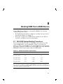
8.1
VAX 6000 System Booting Procedures . . . . . . . . . . . . . .
8.1.1
Boot Command for 6000-500 and 6000-600 Systems .
8.1.2
Boot Command for 6000-200, -300, and -400 Systems
8.2
VAX 9000 System Booting Procedure . . . . . . . . . . . . . . .
.
.
.
.
.
.
.
.
.
.
.
.
.
.
.
.
8–1
8–2
8–3
8–4
Overview . . . . . . . . . . . . . . . . . . . . . . . . . . . . . . . . . . . . . . . .
Using EVUCM . . . . . . . . . . . . . . . . . . . . . . . . . . . . . . . . . . . .
9–1
9–2
8
9
9.1
9.2
Booting VMS from a DSSI Device
EEPROM Update Utility
Glossary
Index
vi Contents
Figures
1–1
1–2
1–3
1–4
1–5
1–6
1–7
1–8
1–9
3–1
3–2
3–3
3–4
3–5
5–1
5–2
5–3
KFMSA (-BA) Module . . . . . . . . . . . . . . . . . . . . . . . . . . .
Single System DSSI Configuration . . . . . . . . . . . . . . . . . .
DSSI VAXcluster Configuration . . . . . . . . . . . . . . . . . . . .
VAX 6000 Series System . . . . . . . . . . . . . . . . . . . . . . . . .
VAX 9000 Model 200 System . . . . . . . . . . . . . . . . . . . . . .
VAX 9000 Model 400 System . . . . . . . . . . . . . . . . . . . . . .
XMI Card Cage . . . . . . . . . . . . . . . . . . . . . . . . . . . . . . . .
XMI Backplane (VAX 6000 Series) . . . . . . . . . . . . . . . . . .
XMI Backplane (VAX 9000 Series) . . . . . . . . . . . . . . . . . .
CK-KFMSA-LJ Cable I/O Panel . . . . . . . . . . . . . . . . . . . .
CK-KFMSA-LN Cable I/O Panel . . . . . . . . . . . . . . . . . . .
VAX 6000 Backplane to I/O Panel Cabling . . . . . . . . . . . .
VAX 9000 Model 400 Backplane to I/O Bulkhead Cabling
VAX 9000 Model 200 Backplane to I/O Bulkhead Cabling
Single System KFMSA/DSSI Configuration Sheet . . . . . .
KFMSA/DSSI VAXcluster Configuration Sheet (2 Host) . .
KFMSA/DSSI VAXcluster Configuration Sheet (3 Host) . .
.
.
.
.
.
.
.
.
.
.
.
.
.
.
.
.
.
.
.
.
.
.
.
.
.
.
.
.
.
.
.
.
.
.
.
.
.
.
.
.
.
.
.
.
.
.
.
.
.
.
.
1–2
1–3
1–3
1–6
1–8
1–9
1–10
1–12
1–12
3–4
3–5
3–6
3–10
3–11
5–2
5–3
5–4
.
.
.
.
.
.
.
.
.
.
.
.
.
.
.
.
.
.
.
.
.
.
.
.
.
.
.
.
.
.
1–4
1–4
1–13
4–2
5–11
5–13
7–15
7–17
8–1
9–3
Tables
1–1
1–2
1–3
4–1
5–1
5–2
7–1
7–2
8–1
9–1
Functional Specifications . . . . . . . . . . . . . .
Environmental Specifications . . . . . . . . . . .
KFMSA Cable Kits . . . . . . . . . . . . . . . . . .
POST LED Fatal Error Codes . . . . . . . . . .
Parameter Keywords . . . . . . . . . . . . . . . . .
VAX/DS Diagnostics for DSSI devices . . . .
EVCXF Diagnostic Tests . . . . . . . . . . . . . .
Configuration Utility Command Summary .
Minimum Console Code Revisions . . . . . . .
EVUCM Test Sections . . . . . . . . . . . . . . . .
.
.
.
.
.
.
.
.
.
.
.
.
.
.
.
.
.
.
.
.
.
.
.
.
.
.
.
.
.
.
.
.
.
.
.
.
.
.
.
.
.
.
.
.
.
.
.
.
.
.
.
.
.
.
.
.
.
.
.
.
.
.
.
.
.
.
.
.
.
.
.
.
.
.
.
.
.
.
.
.
.
.
.
.
.
.
.
.
.
.
.
.
.
.
.
.
.
.
.
.
.
.
.
.
.
.
.
.
.
.
About This Manual
This manual explains how to install one or more KFMSA modules in
an XMI based host system. It includes hardware installation, cabling,
diagnostics, and configuration of the DSSI integrated storage elements
(ISEs) attached to the KFMSA module’s two DSSI buses.
Manual Structure
The manual includes the following chapters:
•
Chapter 1, General Information, describes the KFMSA module, the
XMI card cage and backplane, and the DSSI cables used in the
installation.
•
Chapter 2, Unpacking Instructions, provides unpacking instructions.
•
Chapter 3, KFMSA Module Installation, explains how to install the
KFMSA module and DSSI cables in an XMI based host enclosure.
•
Chapter 4, Power-On Self-Test, describes the power-on self-test
(POST) that runs when power is applied to the KFMSA module.
•
Chapter 5, Configuration Concepts describes the configuration
concepts required to properly set DSSI subsystem parameters.
•
Chapter 6, Configuration Using EVCXE, describes how to set device
parameters for the KFMSA module and the DSSI ISEs using EVCXE.
•
Chapter 7, Configuration Using EVCXF, describes how to set device
parameters for the KFMSA module and DSSI ISEs, using EVCXF. It
also contains descriptions of EVCXF tests and commands.
•
Chapter 8, Booting VMS from a DSSI Device, discusses the procedure
for booting the VMS operating system from a DSSI device through the
KFMSA module.
•
Chapter 9, EEPROM Update Utility, describes the EEPROM update
utility (EVUCM).
vii
viii About This Manual
Intended Audience
This manual is intended for use by Digital Customer Services personnel
or qualified self-maintenance customers. If you have not been trained to
install the KFMSA module, you should call Digital Customer Services to
schedule an installation.
For the Customer
The customer must back up the software before Digital Customer Services
personnel arrive at the site. This is important because it ensures that
data is not lost during the installation.
The KFMSA module is susceptible to damage by static electricity. Wear
an antistatic wrist strap and use an antistatic mat whenever you handle
a KFMSA module.
To install the KFMSA module, follow the procedures outlined in this
manual. If you have any difficulty installing the module, call Digital
Customer Services for help.
For Digital Customer Services Personnel
The KFMSA module is susceptible to damage by static electricity. Wear
an antistatic wrist strap and use an antistatic mat whenever you handle
a KFMSA module.
To install the KFMSA module, follow the procedures outlined in this
manual. When you have installed the module, submit a labor activity
reporting system (LARS) form. If you need help completing this form,
contact your unit manager.
1
General Information
This chapter provides an overview of the KFMSA module, the XMI card
cage and backplane, and the DSSI cables used for this installation.
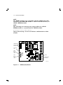
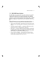
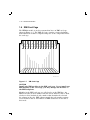
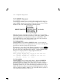
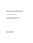
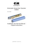
1.1 KFMSA Module
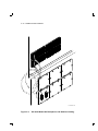
The KFMSA module (Figure 1–1) is an extended memory interconnect
(XMI) storage adapter that connects the host to DSSI based integrated
storage elements (ISEs). The KFMSA has two DSSI buses, each capable
of supporting up to seven DSSI devices. Each DSSI bus has its own
support hardware, including the DSSI bus drivers, bus protocol controller,
host port controller, memory, and RISC processor.
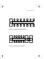
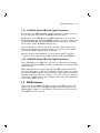
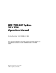
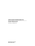
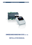
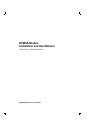
Figures 1–2 and 1–3 illustrate the relationships between the host, the
KFMSA module, and the DSSI ISEs.
There are two different versions of the KFMSA module; KFMSA-AA and
KFMSA-BA. The KFMSA-AA module has terminators embedded in the
module, while the KFMSA-BA module has socketed terminators which
can be removed to allow the module to be used in the middle of the DSSI
bus in a DSSI VAXcluster. The KFMSA-AA module is supported by VMS
Version 5.4-2 or higher. The KFMSA-BA module is supported by VMS
Version 5.4-3 or higher.
NOTE
If you are using VMS 5.4-2 and creating an RF series VMS system
disk on a VAX 6000 series system, you must first install VMS
Version T5.4-0K on the RF ISE, and then update to VMS Version
5.4-2.
If you are using VMS Version 5.4.3, you must also install Version
T5.4-0K first if you are installing VMS from a tape. If you are
installing it from a CD, Version T5.4-0K is included.
1–1
1–2 General Information
NOTE
The KFMSA module is not compatible with the CIBCA-AA module.
Upgrade to the CIBCA-BA module or other CI interface before you
install a KFMSA module.
NOTE
The following error message may appear when you add the
KFMSA module to a system that has a KLESI module.
Maintenance sanity timer expired.
Ignore this message. It does not indicate a malfunction in either
module.
TERMINATOR
SOCKET
SPARES
YELLOW
LED
DSSI
BUS 1
FAULT
LEDS
DSSI
BUS 2
FAULT
LEDS
MSB
LSB
MSB
LSB
FUSES
TERMINATOR
SOCKETS
LJ-00986-TI0
Figure 1–1
KFMSA (-BA) Module
General Information 1–3
HOST
SYSTEM 1
ISE
0
ISE
1
ISE
2
ISE
3
ISE
4
ISE
5
ISE
6
4
ISE
5
ISE
6
ISE
7
DSSI BUS 1
KFMSA
DSSI BUS 2
7
0
ISE
1
ISE
2
ISE
3
ISE
SHR-XR0049-90
Figure 1–2
HOST
SYSTEM 1
Single System DSSI Configuration
ISE
0
ISE
1
ISE
2
ISE
3
ISE
4
7
HOST
SYSTEM 2
5
DSSI BUS 1
KFMSA
HOST
SYSTEM 3
6
KFMSA
KFMSA
5
6
DSSI BUS 2
7
0
ISE
1
ISE
2
ISE
3
ISE
4
ISE
LJ-00984-TI0
Figure 1–3
DSSI VAXcluster Configuration
1–4 General Information
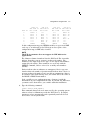
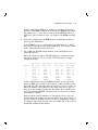
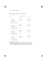
Table 1–1 Functional Specifications
Specification
Value
Throughput
>1000 QIO/second
>2.5 Mbytes/second sustained on either DSSI bus
>4.5 Mbytes/second aggregate
Latency
<1.5 millisecond contribution to transfer time for a
single-sector QIO
Power consumption
15 W nominal
Power requirements
10 A at +5.0 V
Table 1–2 Environmental Specifications
Specification
Value
Temperature
+10 to +40°C (+50 to +104°F), operating
-40 to +66°C (-40 to +151°F), non-operating
Humidity
10% to 90% with no condensation
Altitude
2,438 meters (8,000 feet), operating
9,142 meters (30,000 feet), non-operating
General Information 1–5
1.2 VAX 6000 Series System
The VAX 6000 series system has configurations that support many
different applications. It functions as a standalone system, a VAXcluster
member, a local area VAXcluster boot node, or as a file server for
workstations. It supports a full range of VAX applications and operating
systems.
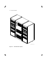
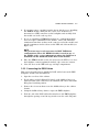
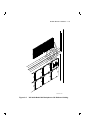
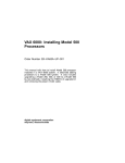
The VAX 6000 series system cabinet is shown in Figure 1–4. The 60-inch
cabinet contains:
•
An XMI card cage (which contains the processors, memories, and I/O
adapters)
•
Two optional VAXBI card cages
•
Two storage bays for optional storage devices and battery backup
•
A tape backup device
•
Control panel switches, status indicators, and restart controls
In the system shown in Figure 1–4, multiple KFMSA modules connect
the VAX 6000 to DSSI disk and tape ISEs in two SF200 storage arrays.
The SF200 storage array holds up to six SF72 enclosures and two tape
devices.
1–6 General Information
SF
20
0
0
1
2
3
4
5
6
0
1
2
3
4
SF
20
0
5
6
0
1
2
3
4
5
6
0
1
2
3
4
5
6
SHR-X0123-90
Figure 1–4
VAX 6000 Series System
General Information 1–7
1.3 VAX 9000 Series System
The VAX 9000 series systems come in two basic models; the model 200
and the model 400. Both models are built from the same or similar
components, the differences are mainly in packaging. The VAX 9000
system uses a system control unit (SCU) to interconnect single or multiple
processors, memory, and I/O subsystems. The I/O subsystem uses the
XMI bus to support the corporate interconnect architectures: BI, CI and
NI.
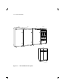
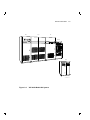
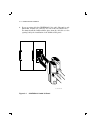
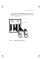
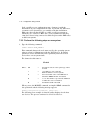
Typical VAX 9000 series system configurations are shown in Figure 1–5
and Figure 1–6. The basic components of the VAX 9000 system are:
•
System Control Unit (SCU) — provides the interconnect between the
service processor unit (SPU), CPU, I/O subsystem, and main memory
arrays.
•
Central Processing Unit (CPU) — contains the CPU planar module
and associated power, cooling, and logic components.
•
I/O Cabinet — contains the XMI card cage(s) and power components.
The model 200 system has a Front End Cabinet (FEC) that contains
one XMI card cage. Model 400 systems have one or two I/O cabinets
(IOA and IOB), each containing two XMI card cages.
•
Storage Enclosure (SF200) — contains DSSI based disk and tape
storage devices. The SF200 cabinet holds up to six SF72 enclosures
(24 disk ISEs maximum) and two tape devices.
1–8 General Information
SCU
CPU
I/O
SF200
VAX 9000
UPC
LJ-00832-TI0
Figure 1–5
VAX 9000 Model 200 System
General Information 1–9
SCU
VAX
CPU
9 0 00
I/O
SF200
UPC
LJ-00833-TI0
Figure 1–6
VAX 9000 Model 400 System
1–10 General Information
1.4 XMI Card Cage
The KFMSA module is used in systems that have an XMI card cage,
shown in Figure 1–7. The XMI card cage contains a 14-slot backplane,
that handles the transfer of signals and power to the components inside
the card cage.
E
D
C
B
A
9
8
7
6
5
4
3
2
1
SHR-X0173-90
Figure 1–7
XMI Card Cage
CAUTION
Install only XMI modules in the XMI card cage. If you install nonXMI modules in the card cage, you may damage the modules or
the XMI backplane.
Modules in the XMI card cage are called nodes on the XMI bus. An
XMI node takes its node number from the slot in which it resides. Each
slot has a 4-bit, hardwired, node number that identifies the slot and
the adapter in the slot. XMI adapters match the node number against
selected address bits to determine if an XMI transaction is directed to
their node.
General Information 1–11
1.4.1 VAX 6000 Series XMI Card Cage Restrictions
Do not install the KFMSA module in slots 6 through 9. These four slots
have no I/O connectors, which the KFMSA module requires.
Furthermore, some VAX 6000 series XMI backplanes do not carry the
interrupt signals that allow the KFMSA module to operate in slots 5 and
A. The VAX 6000-500 and VAX 6000-600 systems carry these signals to
slots 5 and A. Other VAX 6000 models do not.
Also, the first slot or the last slot in the card cage must contain a nonmemory module. If a non-memory module is not present in one of these
two slots, the XMI backplane will not function.
Memory modules must never be placed in slots 1 and E. If slot E is
occupied, it must contain an I/O adapter module such as the KFMSA.
1.4.2 VAX 9000 Series XMI Card Cage Restrictions
In the VAX 9000 series XMI card cage, slot 7 is dedicated to housing the
clock/arbiter module (CCARD) and slot 8 is dedicated to housing the XJA
adapter module.
XMI configuration rules require that the first XMI adapter installed be
placed in either slot 1 or slot 14. If a module is not present in one of these
two slots, the XMI backplane will not function. Other adapters should be
installed in alternate slots, for example: 2, 13, 3, 12, and so on. Adapters
in the higher numbered slots have a higher arbitration priority than those
in the lower numbered slots.
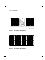
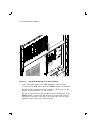
1.5 XMI Backplane
After you place the KFMSA module in a slot in the XMI card cage, you
connect the cables between the XMI backplane and the I/O panel. The
XMI backplane (Figure 1–8 and Figure 1–9) provides two connectors for
each XMI slot in the card cage.
1–12 General Information
SLOTS
1
2
3
4
5
6
7
8
9
A
C
B
D
E
XMI BACKPLANE
SHR-X0171-90
Figure 1–8
1
2
XMI Backplane (VAX 6000 Series)
3
4
5
6
7
8
9
A
B
C
D
E
LJ-00872-TI0
Figure 1–9
XMI Backplane (VAX 9000 Series)
General Information 1–13
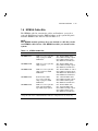
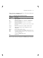
1.6 KFMSA Cable Kits
The KFMSA cable kit contains the cables and hardware you need to
route the DSSI buses from the XMI backplane to the system I/O panel.
Available KFMSA cable kits are listed in Table 1–3.
NOTE
The KFMSA module package does not include a cable kit. Order
one KFMSA cable kit for each KFMSA module you install in the
system.
Table 1–3 KFMSA Cable Kits
Part Number
Used For
Contents of Kit
CK-KFMSA-LJ
VAX 6000 series systems;
single-system or DSSI
VAXcluster1
Two
One
One
Two
CK-KFMSA-LK
VAX 9000 series systems;
single-system
Two 48-inch DSSI cables
One bulkhead adapter plate
Two DSSI bus terminators
CK-KFMSA-LN
VAX 6000 series systems;
single-system or DSSI
VAXcluster
Two 48-inch DSSI "Y" cables
One bulkhead adapter plate,
with DSSI node ID switches
Four DSSI bus terminators
CK-KFMSA-LP
Rack-mounted VAX
6000 series systems;
single-system or DSSI
VAXcluster1
Two
One
One
Two
108-inch DSSI cables
bulkhead adapter plate
bulkhead filler plate
DSSI bus terminators
CK-KFMSA-LR
VAX 6000 series systems
with embedded DSSI
tape ISE; single-system
One
One
One
One
Two
48-inch DSSI cable
125-inch DSSI cable
bulkhead adapter plate
bulkhead filler plate
DSSI bus terminators
1 Using
48-inch DSSI cables
bulkhead adapter plate
bulkhead filler plate
DSSI bus terminators
this cable kit in a DSSI VAXcluster limits the configuration to two hosts only.
1–14 General Information
All of the cable kits listed in Table 1–3 are for connection between the
XMI backplane and the I/O bulkhead. The type of cable you install with
the KFMSA module depends on the configuration you want to end up
with.
For applications where the KFMSA module(s) will be physically
configured on the end(s) of the DSSI bus, use the straight cable; CKKFMSA-LJ for VAX 6000 series systems and CK-KFMSA-LK for VAX
9000 series systems. The bulkhead adapter for this type of cable has two
DSSI connectors on it, one for each of the module’s two DSSI ports (see
Figure 3–1).
For applications where it is desirable to configure a KFMSA with a DSSI
node ID in the middle of the DSSI bus, or to terminate the bus off the
module, use the Y-cables; CK-KFMSA-LN for VAX 6000 series systems.
The bulkhead adapter for this type of cable has four DSSI connectors
on it, plus a rotary switch for setting the DSSI node ID for each of the
module’s two DSSI ports (see Figure 3–2). The rotary switch allows you
to override the DSSI node ID set by the VAX/DS diagnostics EVCXF or
EVCXE.
Configurations using the straight cable kit are restricted to one or two
hosts. The Y-cable kit allows KFMSA modules to be used in the middle
nodes of the DSSI bus, enabling three or more hosts to be used in a DSSI
VAXcluster configuration.
In DSSI VAXcluster configurations using the CK-KFMSA-LN cable kit,
putting the terminators on the bulkhead rather than on the KFMSA
module makes it possible to replace a faulty KFMSA module by only
powering down the system that contains the module, while leaving the
rest of the DSSI devices on the bus(es) active.
The CK-KFMSA-LP is for connecting between XMI backplane and the I/O
bulkhead on rack-mounted VAX 6000 series systems.
The CK-KFMSA-LR is for connecting the KFMSA module to a TF series
DSSI tape device which is internally mounted in a VAX 6000 system.
This kit includes one 48" cable that runs between the backplane and the
bulkhead and one 108" cable that runs from the backplane to the tape
device and then to the bulkhead.
2
Unpacking Instructions
Before you open the package, look for external damage. Report
dents, holes, or crushed corners to the shipper and to your Digital
representative.
Open the package. It contains the KFMSA module and a user manual.
CAUTION
Static electricity can damage integrated circuits. Wear an
antistatic wrist strap and use an antistatic mat whenever
you handle a KFMSA module. An antistatic mat is part of the
antistatic kit (part number 29-26246).
The KFMSA module is wrapped in antistatic material. Do not unpack
the module unless you are wearing an antistatic wrist strap and using an
antistatic mat.
Inspect the KFMSA module for damage. Report the damage to your
Digital representative, and ask for further instructions. If you do not see
any damage, continue with the installation.
2–1
3
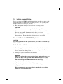
KFMSA Module Installation
This chapter tells you how to install the KFMSA module into the
XMI card cage, and how to connect the DSSI cables between the XMI
backplane and the I/O bulkhead.
Before you start the KFMSA module installation, make sure the system
manager has backed up all files. Have the system manager shut down
the operating system. Make sure these steps have been taken before you
remove any panels from the cabinet.
CAUTION
Only qualified service personnel should install the KFMSA
module. Incorrect installation could damage the module or the
XMI backplane.
CAUTION
Static electricity can damage integrated circuits. Wear an
antistatic wrist strap and use an antistatic mat whenever
you handle a KFMSA module. An antistatic mat is part of the
antistatic kit (part number 29-26246).
3–1
3–2 KFMSA Module Installation
3.1 Before the Installation
Before you start the KFMSA module installation, test the system to verify
its operation. We recommend the following procedure, but you may alter
the procedure as necessary for your site.
1. Have the system manager shut down the operating system.
CAUTION
Make sure the system manager has backed up all files.
2. Initiate the system power-on self-test and be sure it is successful.
Refer to your system documentation for these procedures.
3. Boot the VAX diagnostic monitor and perform a complete system-level
diagnostic test. Be sure that these diagnostics are successful.
3.2 Installation in VAX 6000 Systems
CAUTION
You must power down the system before you remove or install any
XMI module.
3.2.1 Module Installation
1. Turn the upper keyswitch on the front control panel to the 0 position.
2. Open the rear door of the logic compartment and push the T switch
on the ac box to the OFF position.
3. Unplug the system from the electrical outlet.
WARNING
After you unplug the system, wait at least 5 minutes before you
touch the XMI card cage. The 300 Vdc bus discharges slowly.
If you touch the card cage too soon, you may be hurt and you
may also damage the XMI modules in the card cage.
4. Open the front door of the logic compartment.
5. Open the clear plastic door in front of the XMI card cage.
CAUTION
Wear an antistatic wrist strap that is attached to the cabinet
whenever you install modules.
KFMSA Module Installation 3–3
6. If you must remove a module from the slot in which you are installing
the KFMSA module, firmly lift the release lever from the zero
insertion force (ZIF) connection on the backplane and carefully slide
the module out of the card cage slot.
7. If you are installing a KFMSA-BA module in a configuration which
does not require termination at the module, remove the DSSI bus
terminators from their sockets on the connector end of the module and
put the terminators in the sockets on the LED end of the module (see
Figure 1–1).
NOTE
The previous step is only necessary in DSSI VAXcluster
configurations where the KFMSA module is used in one of
the middle nodes, or in configurations where the DSSI bus is
terminated at the bulkhead rather than at the module.
8. Place the KFMSA module in the slot and secure the ZIF lever to close
the backplane contacts against the module edge connector contacts.
9. Close the doors to the XMI card cage and logic compartment.
3.2.2 Connecting the DSSI Cables
This section describes how to install the DSSI cables between the XMI
backplane and the host I/O bulkhead.
1. Open the rear door of the cabinet.
2. Decide where on the bulkhead I/O panel or the bulkhead tray you
want the DSSI cable connectors to be installed and remove the blank
filler plate from that position.
3. Remove the six screws that secure the bulkhead tray to the cabinet
chassis.
4. Swing the bulkhead tray down to expose the XMI backplane.
5. Feed the end of the DSSI cables that attaches to the XMI backplane
through the opening created in step 2 and secure the cable I/O panel.
3–4 KFMSA Module Installation
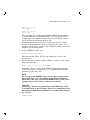
6. If you are using cable kit CK-KFMSA-LJ, the cable I/O panel is only
half-width, and has one connector for each of the two DSSI buses.
You must install the bulkhead filler plate from the cable kit over the
opening left by the installation of the bulkhead I/O panel.
LJ-01100-TI0
Figure 3–1
CK-KFMSA-LJ Cable I/O Panel
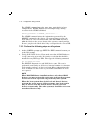
KFMSA Module Installation 3–5
If you are using cable kit CK-KFMSA-LN, the cable I/O panel is full
width, so there is no need for a filler plate. On this version of the
cable kit there are two connectors plus a DSSI node ID select rotary
switch for each DSSI bus.
3 4 5
2
1
3 4 5
6
7
0
Off
2
1
6
7
0
Off
DSSI TERMINATOR
LJ-00983-TI0
Figure 3–2
CK-KFMSA-LN Cable I/O Panel
3–6 KFMSA Module Installation
LJ-00987-TI0
Figure 3–3
VAX 6000 Backplane to I/O Panel Cabling
7. Connect the DSSI cables to the XMI backplane connectors that
correspond to the XMI slot in which the KFMSA module was installed.
Each slot in the backplane has four connectors. The top two are D1
and D2, and the bottom two are E1 and E2.
The top two I/O connectors (D1 and D2) connect to DSSI bus 1 on the
KFMSA module. Connect J1 and J2 from one of the DSSI cables to
D1 and D2, respectively. The other end of this cable connects to the
rightmost connector(s) on the cable I/O panel.
KFMSA Module Installation 3–7
The bottom two I/O connectors (E1 and E2) connect to DSSI bus 2 on
the KFMSA module. Connect J1 and J2 from the other DSSI cable to
E1 and E2, respectively. The other end of this cable connects to the
leftmost connector(s) on the cable I/O panel.
NOTE
Notice that the orientation of pin 1 is marked on both cable
connectors, and make sure you install the cables accordingly
on the backplane.
NOTE
In some rackmounted systems the backplane is mounted
upside down. Make sure to note the orientation of pin 1 before
installing the cables.
When you install more than one KFMSA module in a system, you
must follow the cabling conventions described in the preceding
paragraphs. Use the color-coded labels at each connector end of a
cable to facilitate maintenance. Be sure to record the label colors on a
configuration sheet.
8. Close the I/O bulkhead tray and replace the six screws.
9. Connect the DSSI cables between the I/O panel connectors and the
DSSI devices (if any) you are connecting to the KFMSA module. Refer
to your system or option documentation for these procedures.
NOTE
Unused DSSI buses must be terminated with the DSSI bus
terminator from the cable kit.
10. Close and lock the rear door of the cabinet.
11. Power on the system. This initiates the power-on self-test (POST)
described in the next chapter.
3–8 KFMSA Module Installation
3.3 Installation in VAX 9000 Systems
CAUTION
You must power down the system before you remove or install any
XMI module.
3.3.1 Module Installation
Prior to opening the I/O cabinet, perform the normal operating system
shutdown procedures. Power off the system, disconnect power, and lock
out the system from the ac power source.
Make sure the three keys on the OCP are set in the following position:
Key
Position
Power
Off
Startup
Halt
Service Processor Access
Local/SPU
WARNING
This procedure may expose you to line voltage on the Auxiliary
Power circuit breaker (CB1) located in the lower rear section of
the I/O cabinet if the UPC is not properly shut down and locked
out. This voltage will be present even if CB1 is in the off position.
1. Open front door of the cabinet, and the clear plastic door in front of
the XMI card cage.
CAUTION
Wear an antistatic wrist strap that is attached to the cabinet
whenever you install modules.
2. If you must remove a module from the slot in which you are installing
the KFMSA module, firmly lift the release lever from the zero
insertion force (ZIF) connection on the backplane and carefully slide
the module out of the card cage slot.
3. If you are installing a KFMSA-BA module in a configuration which
does not require termination at the module, remove the DSSI bus
terminators from their sockets on the connector end of the module and
put the terminators in the sockets on the LED end of the module (see
Figure 1–1).
KFMSA Module Installation 3–9
NOTE
The above step is only necessary in DSSI VAXcluster
configurations where the KFMSA module is used in one of
the middle nodes, or in configurations where the DSSI bus is
terminated at the bulkhead rather than at the module.
4. Place the KFMSA module in the slot and secure the ZIF lever to close
the backplane contacts against the module edge connector contacts.
3.3.2 Connecting the DSSI Cables
This section describes how to install the DSSI cables between the XMI
backplane and the host I/O bulkhead.
1. Open the rear door of the cabinet.
2. Remove one of the blank panels from the I/O bulkhead assembly. In
the VAX 9000 model 400 I/O cabinet, there is more than one XMI card
cage. If the KFMSA is installed in XMI0, remove a panel from the left
side of the bulkhead assembly. If the KFMSA is installed in XMI1,
remove a panel from the right side of the bulkhead assembly.
3. Feed the DSSI cables through the hole in the bulkhead assembly, and
screw the cable I/O panel to the assembly.
4. Coil the excess length of the DSSI cables behind the I/O bulkhead
assembly in the model 400. In the model 200 (FEC), coil the excess
cable around the plastic bar behind the XMI backplane.
5. Connect the two DSSI cables to the XMI backplane connectors that
correspond to the card cage slot in which the KFMSA module was
installed.
Each slot in the backplane has four connectors. The top two are D1
and D2, and the bottom two are E1 and E2.
The top two I/O connectors (D1 and D2) connect to DSSI bus 1 on the
KFMSA module. Connect J1 and J2 from one of the DSSI cables to
D1 and D2, respectively. The other end of this cable connects to the
rightmost connector the cable I/O panel.
3–10 KFMSA Module Installation
LJ-00873-TI0
Figure 3–4
VAX 9000 Model 400 Backplane to I/O Bulkhead Cabling
KFMSA Module Installation 3–11
LJ-00874-TI0
Figure 3–5
VAX 9000 Model 200 Backplane to I/O Bulkhead Cabling
3–12 KFMSA Module Installation
The bottom two I/O connectors (E1 and E2) connect to DSSI bus 2 on
the KFMSA module. Connect J1 and J2 from the other DSSI cable to
E1 and E2, respectively. The other end of this cable connects to the
leftmost connector on the cable I/O panel.
Notice that the orientation of pin 1 is marked on both cable
connectors, and make sure you install the cables accordingly on
the backplane.
When you install more than one KFMSA module in a system, you
must follow the cabling conventions described in the preceding
paragraphs. Use the color-coded labels at each connector end of a
cable to facilitate maintenance. Be sure to record the label colors on a
configuration sheet.
6. Connect the DSSI cables between the I/O bulkhead connectors and the
DSSI devices (if any) you will connect to the KFMSA module. Refer to
your system or option documentation for these procedures.
NOTE
Unused DSSI buses must be terminated with the DSSI bus
terminator from the cable kit.
7. Close all cabinet doors.
8. Plug in and power on the system. This initiates the power-on self-test
(POST) described in the next chapter.
4
Power-On Self-Test
The KFMSA module has a power-on self-test (POST). It performs a
comprehensive set of logic tests when power is applied to the module, or
when the host invokes a node reset.1 The POST provides test coverage for
about 98% of the module logic and takes about 10 seconds to run.
The KFMSA module has one yellow LED and eight red LEDs. (Four
red LEDs correspond to each DSSI port on the module.) The LEDs are
mounted on the module edge, as shown in Figure 1–1.
When power is first applied, all red LEDs should turn on. Each port on
the module is tested independently. When a port passes the tests, its four
red LEDs turn off. If the POST detects no errors, all eight red LEDs turn
off and the yellow LED turns on.
When the POST detects a fatal error, the red LEDs display the error
code(s), but the yellow LED remains off. Table 4–1 defines the POST LED
fatal error codes.
When one port fails and the other port passes the POST, the red LEDs
that correspond to the DSSI port that failed display an error code, the
module runs in single-port mode, and the yellow LED remains on.
1
Node reset does not effect other modules in the XMI system. It does reinitialize
both ports of the KFMSA module and rerun the POST.
4–1
4–2 Power-On Self-Test
Table 4–1 POST LED Fatal Error Codes
Red LEDs
MSB
Error Code Meaning
LSB
Never got started or failed ROM tests
CP bus timeout test failure
CAM test failure
Interrupt register test failure
XPC test failure
Parity test failure
PBM test failure
Extended HIS DMA channel test failure
XPC self-directed command failure
PBM self-directed command failure
DASHAC self-directed command failure
CP bus/octaword NACK self-directed command failure
DASHAC-to-DASHAC interrupt test failure
LED lit
Contention test failure
DSSI loopback test failure
This port passed POST
LED unlit
5
Configuration Concepts
After you install the KFMSA module and the POST has run successfully,
you must configure the DSSI subsystem.
This chapter describes the physical address requirements and the
software parameters of the DSSI subsystem. It explains the naming
conventions used by the VMS operating system, and gives you some
guidelines to follow.
Be sure you understand the concepts described in this chapter before you
configure a DSSI subsystem, using the procedures detailed in Chapter 6
or Chapter 7.
5.1 Physical Address Requirements
Each component in the DSSI subsystem has an address. Part of the
address is determined by the physical location of the component in the
DSSI subsystem, and part of the address is set during the KFMSA module
installation. Fill in the information on a configuration sheet (see Figures
5–1 through 5–3) when you install the KFMSA module. When you have
a configuration sheet that includes this information, the configuration
process is easier.
5–1
5–2 Configuration Concepts
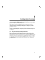
KFMSA/DSSI Single-host Configuration Sheet
KFMSA XMI Node #
Bus 1
DSSI ID #
Device Type
DSSI ID #
Node Name
ALLO_CLASS
SF200 Box #
UNITNUM
System ID
Device Type
DSSI ID #
Node Name
ALLO_CLASS
SF200 Box #
UNITNUM
ALLO_CLASS
SF200 Box #
UNITNUM
ALLO_CLASS
SF200 Box #
UNITNUM
ALLO_CLASS
SF200 Box #
UNITNUM
Device Type
DSSI ID #
Node Name
ALLO_CLASS
SF200 Box #
UNITNUM
Device Type
DSSI ID #
Node Name
ALLO_CLASS
SF200 Box #
UNITNUM
Device Type
DSSI ID #
Node Name
ALLO_CLASS
SF200 Box #
UNITNUM
System ID
ALLO_CLASS
SF200 Box #
UNITNUM
System ID
Device Type
DSSI ID #
Node Name
ALLO_CLASS
SF200 Box #
UNITNUM
System ID
System ID
Device Type
DSSI ID #
Node Name
Device Type
DSSI ID #
Node Name
System ID
System ID
Device Type
DSSI ID #
Node Name
ALLO_CLASS
SF200 Box #
UNITNUM
System ID
System ID
Device Type
DSSI ID #
Node Name
Device Type
DSSI ID #
Node Name
System ID
System ID
Device Type
DSSI ID #
Node Name
Bus 2
DSSI ID #
Device Type
DSSI ID #
Node Name
ALLO_CLASS
SF200 Box #
UNITNUM
System ID
ALLO_CLASS
SF200 Box #
UNITNUM
System ID
Device Type
DSSI ID #
Node Name
ALLO_CLASS
SF200 Box #
UNITNUM
System ID
Color Code
on Cables
Color Code
on Cables
SHR-X0109-90
Figure 5–1
Single System KFMSA/DSSI Configuration Sheet
Configuration Concepts 5–3
KFMSA/DSSI Dual-host Configuration Sheet
KFMSA XMI Node #
Bus 1
DSSI ID #
Device Type
DSSI ID #
Node Name
Bus 2
DSSI ID #
ALLO_CLASS
SF200 Box #
UNITNUM
Device Type
DSSI ID #
Node Name
System ID
Device Type
DSSI ID #
Node Name
System ID
ALLO_CLASS
SF200 Box #
UNITNUM
Device Type
DSSI ID #
Node Name
System ID
Device Type
DSSI ID #
Node Name
ALLO_CLASS
SF200 Box #
UNITNUM
Device Type
DSSI ID #
Node Name
ALLO_CLASS
SF200 Box #
UNITNUM
System ID
ALLO_CLASS
SF200 Box #
UNITNUM
Device Type
DSSI ID #
Node Name
System ID
Device Type
DSSI ID #
Node Name
ALLO_CLASS
SF200 Box #
UNITNUM
System ID
System ID
Device Type
DSSI ID #
Node Name
ALLO_CLASS
SF200 Box #
UNITNUM
ALLO_CLASS
SF200 Box #
UNITNUM
System ID
ALLO_CLASS
SF200 Box #
UNITNUM
Device Type
DSSI ID #
Node Name
System ID
ALLO_CLASS
SF200 Box #
UNITNUM
System ID
Bus 1
DSSI ID #
Bus 2
DSSI ID #
KFMSA XMI Node #
Color Code
on Cables
Color Code
on Cables
SHR-X0133-90
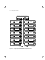
Figure 5–2
KFMSA/DSSI VAXcluster Configuration Sheet (2 Host)
5–4 Configuration Concepts
KFMSA/DSSI VAXcluster Configuration Sheet
KFMSA XMI Node #
Bus 1
DSSI ID #
Bus 2
DSSI ID #
KFMSA XMI Node #
Bus 1
DSSI ID #
Device Type
DSSI ID #
Node Name
Bus 2
DSSI ID #
Device Type
DSSI ID #
Node Name
ALLO_CLASS
SF200 Box #
UNITNUM
System ID
Device Type
DSSI ID #
Node Name
System ID
Device Type
DSSI ID #
Node Name
ALLO_CLASS
SF200 Box #
UNITNUM
System ID
Device Type
DSSI ID #
Node Name
Device Type
DSSI ID #
Node Name
ALLO_CLASS
SF200 Box #
UNITNUM
ALLO_CLASS
SF200 Box #
UNITNUM
System ID
Device Type
DSSI ID #
Node Name
ALLO_CLASS
SF200 Box #
UNITNUM
System ID
Device Type
DSSI ID #
Node Name
ALLO_CLASS
SF200 Box #
UNITNUM
System ID
System ID
Device Type
DSSI ID #
Node Name
ALLO_CLASS
SF200 Box #
UNITNUM
ALLO_CLASS
SF200 Box #
UNITNUM
System ID
Device Type
DSSI ID #
Node Name
ALLO_CLASS
SF200 Box #
UNITNUM
System ID
ALLO_CLASS
SF200 Box #
UNITNUM
System ID
Bus 1
DSSI ID #
Bus 2
DSSI ID #
KFMSA XMI Node #
Color Code
on Cables
Color Code
on Cables
LJ-00982-TI0
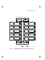
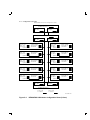
Figure 5–3
KFMSA/DSSI VAXcluster Configuration Sheet (3 Host)
Configuration Concepts 5–5
5.1.1 XMI Node Number
The XMI node number is hardwired in the XMI backplane. You set the
XMI node number when you insert the KFMSA module in one of the
valid I/O slots in the XMI card cage. XMI node numbers are hexadecimal
numbers. They start with 1 at the rightmost slot of the backplane, and
they proceed to the left.
Make note of the XMI node number for the KFMSA module on the
configuration sheet.
5.1.2 DSSI Bus Number
The KFMSA module has two separate DSSI buses (ports). Each of the
buses presents a discrete set of registers to the host. For communication
to occur, the host software must ‘‘know’’ which DSSI bus is attached to
which ISE. The DSSI buses are called bus 1 and bus 2.
You do not set the DSSI bus numbers in the KFMSA module or in
the ISEs. They are determined by the cable connections from the
XMI backplane, through the bulkhead connectors, to the SFxx storage
enclosure(s).
The cable connected to the top pair of I/O connectors on the XMI
backplane is DSSI bus 1. The cable connected to the lower pair of I/O
connectors is DSSI bus 2.
Use the color-coded labels at each connector end of a cable to facilitate
maintenance. Be sure to record the label colors on the configuration sheet.
NOTE
Some rackmounted VAX 6000 systems have the backplane
mounted upside down. Check proper orientation before labelling
the DSSI buses.
NOTE
The DSSI bus numbers are not cumulative across the system. For
each KFMSA module in a system, the DSSI buses are called bus 1
and bus 2.
5–6 Configuration Concepts
5.1.3 DSSI Node ID
Each ISE or module connected to a DSSI bus must have a unique bus
address. This address is called the DSSI node ID. It is always in the
range of 0 to 7.
5.1.3.1 Setting the DSSI Node ID for an ISE
The user sets the DSSI node IDs for the ISEs. If the ISEs are in an SFxx
enclosure, the user sets the switches on the SFxx operator control panel
(OCP). An LED display next to the switchpack shows you the values you
have selected.
NOTE
The ISE does not use the new value you selected until the next
time it is powered up.
In addition to the switches on the OCP, ISEs have switches mounted
on their electronics modules. The user sets the switches on the ISE
electronics module only if the ISE is not connected to an OCP. When
the ISE is connected to an OCP, the switches on the OCP override the
switches on the electronics module.
Be sure you write the DSSI node ID for every ISE in your system on the
configuration sheet.
5.1.3.2 Setting the DSSI Node ID for a KFMSA Module
The DSSI node IDs for the KFMSA modules are factory set to 7. Both
ports have the same DSSI node ID. You should never need to reset the
DSSI node IDs for a single system DSSI system.
To set the DSSI node ID for a KFMSA module, use the software tools
described in Section 5.6. If using a cable kit with a remote select switch
on the bulkhead I/O panel, such as the CK-KFMSA-LN, you can set
the DSSI node ID by setting the rotary switch on the I/O panel to the
appropriate number for each DSSI bus.
NOTE
The CK-KFMSA-LN rotary switch setting overrides the software
setting.
NOTE
A node reset is required before the new DSSI node ID can be read.
Configuration Concepts 5–7
For a DSSI VAXcluster configurations, you reset the DSSI node ID of all
but one of the KFMSA modules on the shared bus. Make sure that every
device, including each KFMSA module, has a unique DSSI node ID on
each DSSI bus. We recommend that you set the DSSI node number for
the second KFMSA module to 6, the third KFMSA module to 5, etc.
5.2 DSSI Software Parameters
In addition to the physical address requirements, the ISEs and operating
system (OS) software use software parameters to communicate with each
other.
NOTE
The ISEs require the following software parameters. These
parameters do not apply to the KFMSA module.
•
System ID — Also called the SCA system address, the node address,
or the SCA system ID. This 48-bit numeric value must be unique
across the entire system topology in which the device is configured.
A DSSI device takes the most unique part of its serial number as
its system ID. In most cases, this default value is a unique number
within the system.
•
Node name — Also called the SCA node name, or (SCA) system
name. This 8-character ASCII value must be unique across the
system topology in which the device is configured.
A DSSI device generates its node name as follows. It takes two
characters from its device type (for example, an RF72 takes R7), and
adds four alpha-numeric characters from a compaction of its serial
number. In most cases, this default value is a unique number within
the system.
•
MSCP or TMSCP unit number — This is a 16-bit numeric value. A
DSSI device uses the ISE’s DSSI node ID as its default value. Under
software control, the user can set a unique value. The operating
system requirements for this value vary, depending on the state of
other parameters.
•
Allocation class — This 8-bit numeric value indicates whether an
ISE is to be served by its host to other members of a cluster. The
default value is 0, which indicates the ISE is not to be served.
5–8 Configuration Concepts
To enable the device to be served, set this value to match the
allocation class value of the host system. (The allocation class
value of the host system is a VMS SYSGEN parameter called
ALLOCLASS. Refer to VMS documents for more information on
SYSGEN parameters.)
•
Force name — The default value for this 1-bit control field is 0.
When you set this value to 1, the ISE uses its option name (for
example, RF72) as its node name, rather than a value derived from
its serial number.
•
Force unit — The default value for this 1-bit control field is 1. When
you set this value to 0, the ISE uses a unique, user-set value as its
MSCP or TMSCP unit number, rather than its DSSI node ID.
5.3 VMS Naming Conventions
The VMS operating system builds unique device names from information
the ISE or module presents and some generic naming conventions.
NOTE
The following paragraphs provide some background information.
They explain how the VMS naming conventions are currently used
for DSSI storage devices. Some of the naming conventions have
different uses in other storage families or classes of products.
5.3.1 Device Naming Conventions for ISEs
The DSSI disk ISE format for a device name is DIAn, where n is the
MSCP unit number of a specific ISE. Some examples of DSSI disk names
are DIA0, DIA1, and DIA2. The VMS operating system adds either the
node name or the allocation class to this part of the device name.
The DSSI tape ISE format for a device name is MIAn.
When the allocation class for a device is a nonzero value, the VMS
operating system uses it as part of the device name. Thus, the format
for the device name is $allocation_class$DIAn. So, for an ISE with an
allocation class of 1, an example device name is $1$DIA4.
Note that when the allocation class is set to a nonzero value for some or
all of the ISEs in a configuration, unique MSCP or TMSCP unit numbers
must be assigned to all of them, and the force unit field must be set to 0.
When the allocation class is 0, the VMS operating system uses the ISE’s
node name as part of its unique device name. In this case, the format for
the device name is Node_name$DIAn.
Configuration Concepts 5–9
So, if the ISE’s node name is R7XRMA, its allocation class is 0, and its
force unit field is 1, the device name is R7XRMA$DIA4.
5.3.2 Port Naming Conventions for KFMSA Modules
The KFMSA module does not use software parameters. However, the
VMS operating system generates names for the ports that the KFMSA
module presents to the host system. These names appear in a SHOW
DEVICE display.
The format for a port name is PAx0, where x is a letter. Some examples
of port names are PAA0, PAB0, and PAC0. Notice that the letters are
assigned in sequential order. A is used for the first DSSI bus of the first
KFMSA module (that is, the lowest XMI node number), B is used for the
second bus of the same KFMSA module, and so on. Remember that the
KFMSA uses the CI port architecture for communications with its local
host. The presence of a CI adapter in the system may affect the order of
the KFMSA port names.
5.4 Recommended Parameter Settings
Use the following guidelines for the configuration process. Keep in mind
that the DSSI subsystem configuration parameters (as used by the
VMS operating system) may be interdependent. Also, different system
configurations have different requirements.
•
Verify or change all the parameters before you boot the operating
system software. This reduces the time it takes to install a new
KFMSA module in a system.
If a parameter that must be unique matches another parameter, the
operating system does not ‘‘recognize’’ any of the device names that
use those parameters. Also, the operating system does not use the
new values you selected for certain static parameters (such as the
allocation class) until the next time the software is booted.
•
Use unique MSCP or TMSCP unit numbers for all the ISEs in the
system. Start the numbering sequence with DSSI node ID 0 on bus 1
of the first KFMSA module in the system. Remember to set the force
unit field to 0.
•
If the DSSI subsystem is part of a VAXcluster (either DSSI or LAVC),
set the allocation class of the ISEs to a cluster-unique nonzero value.
Remember, all the ISEs must have the same value.
5–10 Configuration Concepts
Be sure that the host system’s allocation class matches the allocation
class of the ISEs. If necessary, set the host system’s allocation class
to the same value with SYSGEN. If the DSSI subsystem is part of a
VAXcluster configuration, set all host systems to the same allocation
class.
NOTE
The TF837 tape ISE does not use the allocation class
parameter.
•
Make sure you have used unique node names for all the ISEs in
the cluster. Unique node names are a requirement, even when the
allocation class is a nonzero value.
•
Do not change the force name.
•
Make sure the system IDs of all ISEs are unique, and change the
system IDs only when you detect a duplicate name.
We suggest that you write the node names on color-coded labels that
come with SFxx enclosures. Affix the labels on the access door(s) of
the operator control panel(s). Be sure you place the labels where they
correspond to the correct ISE. Also, use the color-coded labels at each
connector end of the cables at the rear of the enclosure to facilitate
maintenance.
5.5 Recommended Formats for Node Names
If you use the following formats, the possibility of duplicate node names is
lessened.
RFcxbd or TFcxbd
Where:
RF and TF
=
the first two letters of the option type. RF is for
disk; TF is for tape.
c
=
0 for VAX 6000 series systems,
XJA# for VAX 9000 series systems.
x
=
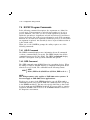
the hexadecimal value of the XMI slot in which
the KFMSA module is installed.
b
=
1 or 2. The number represents the DSSI bus on
which the device is installed.
d
=
the DSSI node ID of the ISE.
Configuration Concepts 5–11
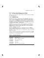
5.6 Configuration Management Tools
This section describes the software tools you will use when you configure
the DSSI subsystem.
5.6.1 PARAMS Utility
All DSSI devices have a utility progam called PARAMS, which allows
you to see the current parameter values of an ISE and change them.
When you invoke PARAMS, the program displays a prompt and waits for
user input. If you type HELP at the prompt, the program lists all the
PARAMS commands. More information on the PARAMS utility program
is available in the ISE user documentation.
PARAMS runs on line by means of DCL commands, or standalone by
means of the VAX diagnostic supervisor (VAX/DS). When you install a
KFMSA module, or when you add a DSSI device, use the standalone
VAX/DS configuration programs.
The three PARAMS commands you will use most often are SHOW,
SET, and WRITE. With these three commands, you can see the current
parameter values of all the devices, one parameter at a time, and change
them as necessary.
Table 5–1 lists the keywords that correspond to the parameters. To find
the value of any one of the device parameters (Section 5.2), type SHOW
followed by the corresponding keyword.
Table 5–1 Parameter Keywords
Keyword
Parameter
ALLCLASS
Allocation class
UNITNUM
MSCP or TMSCP unit number
FORCEUNI
Force unit number flag
SYSTEMID
System ID
NODENAME
Node name
FORCENAM
Force node name to default flag
5–12 Configuration Concepts
For example, to see the current parameter value of an ISE’s allocation
class, type the following command:
PARAMS> show allclass
Parameter
Current
------------------ALLCLASS
0
Default
-----------0
Type
-----Byte
Radix
------Dec
PARAMS>
In response to your command input, PARAMS shows the current and
default values, the type of parameter, and the radix that applies to the
allocation class. To change the value of the allocation class to 5, use the
SET command:
PARAMS>
set allclass 5
Note that the SET command includes the new parameter value, and
remember that this new value is temporary. So if you reset the device,
the new value will be erased and the previous value will be used.
To make the change permanent, use the WRITE command:
PARAMS> set allclass 5
PARAMS> write
Note that no arguments are used with WRITE. After you enter the
WRITE command, PARAMS displays the following message:
Changes require controller initialization, ok? [Y/(N)]
Type Y[es] to store the new values for the ISE. Controller initialization
breaks the PARAMS connection to the ISE, so PARAMS must be invoked
again. Type N[o], and the values you entered with the SET command are
temporary. However, the connection to the ISE remains intact and the
PARAMS> prompt returns.
The WRITE command need only be issued once, after all the changes for
a device have been entered.
Configuration Concepts 5–13
5.6.2 VAX/DS Configuration Programs
Two utility programs, both of which run standalone under the VAX/DS,
can be used to configure the DSSI subsystem.
EVCXE, which is distributed as part of the diagnostic/utility kit that is
shipped with the VAX 6000 series system, lets you access the PARAMS
utility in each ISE and use the PARAMS commands to check or change
the parameter values. It also lets you change the DSSI node IDs of the
two ports on the KFMSA module.
NOTE
EVCXE is not recommended for use on VAX 9000 systems.
EVCXF, the DSSI configuration and DUP diagnostic, is distributed as
part of the diagnostic/utility kit that is shipped with the VAX 9000
series systems. Or it can be purchased as part of the VAX/DS diagnostic
software license from Digital Equipment Corporation.
EVCXF lets you change the parameter values on all the ISEs in the
system, and it uses only a few commands. It also communicates
transparently with the PARAMS utility in the ISEs. You control these
communications through a metacommand set defined within EVCXF.
5.6.3 VAX/DS Diagnostic Programs
Some installations require that you run diagnostic programs to check
the integrity of the KFMSA module and the DSSI ISEs attached to it.
Refer to the KFMSA Module Service Guide, part number EK-KFMSA-SV,
for details on how to run those diagnostics. Table 5–2 lists the VAX/DS
diagnostics that apply to the KFMSA module and DSSI ISEs.
Table 5–2 VAX/DS Diagnostics for DSSI devices
Diagnostic
Description
EVCXD
Repair-level KFMSA diagnostic
EVRAE
Online DSSI disk exerciser
EVMDA
Online DSSI tape exerciser
6
Configuration Using EVCXE
EVCXE is a utility that lets you access the PARAMS local program
in each ISE and use the PARAMS commands to check or change the
parameter values. It also lets you change the DSSI node IDs of the two
ports on the KFMSA module.
NOTE
Although EVCXE will work on VAX 9000 systems, it is
recommended that you use EVCXF instead.
Before you begin, you must:
•
complete the physical installation of the DSSI subsystem,
•
verify the cabling,
•
make sure that all the power-on tests were successful,
•
run the recommended VAX 6000 CPU and memory diagnostics.
Be sure that the KFMSA/DSSI subsystem configuration sheet shows the
correct physical configuration and planned parameter values. Refer to
Chapter 5 for the recommended parameter values. Check off each unit
after you set its parameter values.
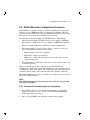
6–1
6–2 Configuration Using EVCXE
6.1 Single System Configuration Procedure
1. Boot VAX/DS. Refer to your system documentation or to the VAX
Diagnostic Supervisor User Guide, order number AA-FK66A-TE for
the appropriate procedures.
2. After you load VAX/DS, the program returns a DS> prompt.
Attach the KFMSA module(s) using one of the following two methods.
If you intend to test the KFMSA module(s) only, use the manual
method. If you intend to test other devices as well, use the automated
method.
Manual method:
Attach the KFMSA module(s) with the following command:
DS> ATTACH KFMSA HUB generic_name XMI_node_number DSSI_bus_number
In this command, the generic_name is in the format PAx0. Use a
different letter in place of the x for each DSSI bus in the system.
The XMI_node_number is a numeric value that indicates which XMI
backplane slot contains the KFMSA module. So, a typical attach
sequence for a system with a KFMSA module installed in slot 4 looks
like this:
DS> ATTACH KFMSA HUB PAA0 4 1
DS> ATTACH KFMSA HUB PAB0 4 2
Automated Method:
At the DS> prompt, type the following:
DS> set flag quick
DS> run evsba/section:selftest
This activates the AUTOSIZER, which prompts you for command
input.
a. At the COMMAND? prompt, type SIZE.
The AUTOSIZER begins to scan the XMI bus, locating the devices.
A series of ATTACH commands appears on the console terminal.
Some of these will correspond to the KFMSA(s) installed in the
system.
Configuration Using EVCXE 6–3
The following is an example of the display:
DS>
DS>
DS>
DS>
ATTACH
ATTACH
ATTACH
ATTACH
KFMSA
KFMSA
KFMSA
KFMSA
HUB
HUB
HUB
HUB
PAA0
PAB0
PAC0
PAD0
4
4
B
B
1
2
1
2
Note that each KFMSA module is listed twice because of the
two DSSI ports on the module. Verify that all the KFMSAs
were found, and that the XMI node number associated with
each module is correct. (The XMI node number is the number
immediately following the PAx0.) You do not need to verify the
attach sequence for the ISEs connected to the KFMSA module
DSSI ports.
b. When the COMMAND? prompt returns, type ATTACH and press
Return .
c.
Exit from AUTOSIZER by typing EXIT at the COMMAND?
prompt.
3. Select the KFMSA(s) you will configure, as shown in the following
example:
DS> Select PAA0,PAB0...
Be sure you include all the generic names associated with the selected
KFMSA modules.
4. Enter the following command:
DS> Run EVCXE
The program prints several lines of identification information, and
then it displays the following message:
Enter XMI Node #, DSSI bus, DSSI node ID # or <CR> to exit test:
At this point, you type the numeric values for the KFMSA port you
attached in step 2. If this is the first time an XMI node number or
DSSI bus number is recognized by EVCXE (new installations), the
program displays the following message:
Enter new KFMSA DSSI Node ID # [(7), 0, 7] or <CR> to keep present value:
For most single system configurations, you do not need to change this
value. Simply press Return .
6–4 Configuration Using EVCXE
The EVCXE program establishes a DUP connection to the ISE
and invokes the resident PARAMS utility. (The PARAMS> prompt
appears.)
NOTE
For more information on the PARAMS utility, refer to the
appropriate ISE User Guide.
5. Use the SHOW command to find the values of the ISE’s system
ID and allocation class. Then write these parameter values on the
configuration sheet.
6. Use the SET command to change the parameter values. For example,
to change the node name to RF0416, type:
PARAMS> set nodename RF0416
If you set MSCP or TMSCP unit numbers for the ISEs, remember to
change the Force Unit Flag as well. For example:
PARAMS> set unitnum 10
PARAMS> set forceuni 0
7. To make the changes permanent, use the WRITE command. The
following message appears.
Changes require controller initialization, ok? [Y/(N)]
Type Y[es] to store the new values for the ISE. Controller initialization
breaks the EVCXE connection to the ISE, but after a brief delay
EVCXE prompts you to select another unit. If you type N[o], the
values you entered with the SET command are not stored. However,
the connection to the ISE remains intact and the PARAMS> prompt
returns.
The WRITE command need only be issued once, after all the changes
for an ISE have been entered.
Configuration Using EVCXE 6–5
6.2 DSSI VAXcluster Configuration Procedure
DSSI ISEs have a built-in ability to maintain simultaneous connections
with two or more KFMSA modules in separate host systems. All host
systems must be in the same local area VAXcluster (LAVC) system. Each
host system can directly access all ISEs connected to it.
The following restrictions apply to DSSI VAXcluster configurations:
•
All host systems must use VMS Version 5.4-2 or higher for KFMSAAA modules, or VMS Version 5.4-3 or higher for KFMSA-BA modules.
•
All host systems must form a VAXcluster system configuration.
•
All cabinets must be powered by the same ac circuit, or if they are
powered by different circuits, those circuits:
•
–
Must not power any other equipment
–
Must share a single ground point
–
Must have a dedicated ground wire between the outlet and the
single ground point
Each ISE must be assigned the same device name and allocation class
on all host systems.
When you install two or more systems in a DSSI VAXcluster
configuration, install each system individually and test it to make sure it
is working correctly. Then remove the terminators and connect the DSSI
extension cable(s) between the systems and/or the expander cabinet(s).
The DSSI VAXcluster procedure is similar to the single system procedure,
with some additional steps.
NOTE
The following steps must be performed in order. Do not perform
any steps in parallel.
6.2.1 Perform the following steps on all systems
1. Boot VAX/DS. Refer to your system documentation or the VAX
Diagnostic Supervisor User’s Guide, order number AA-FK66A-TE,
for the appropriate procedures.
2. After you load VAX/DS, the program returns a DS> prompt.
6–6 Configuration Using EVCXE
Attach the KFMSA module(s) using one of the following two methods.
If you intend to test the KFMSA module(s) only, use the manual
method. If you intend to test other devices as well, use the automated
method.
Manual method:
Attach the KFMSA module(s) with the following command:
DS> ATTACH KFMSA HUB generic_name XMI_node_number DSSI_bus_number
In this command, the generic_name is in the format PAx0. Use a
different letter in place of the x for each DSSI bus in the system.
The XMI_node_number is a numeric value that indicates which XMI
backplane slot contains the KFMSA module. So, a typical attach
sequence for a system with a KFMSA module installed in slot 4 looks
like this:
DS> ATTACH KFMSA HUB PAA0 4 1
DS> ATTACH KFMSA HUB PAB0 4 2
Automated Method:
At the DS> prompt, type the following:
DS> set flag quick
DS> run evsba/section:selftest
This activates the AUTOSIZER, which prompts you for command
input.
a. At the COMMAND? prompt, type SIZE.
The AUTOSIZER begins to scan the XMI bus, locating the devices.
A series of ATTACH commands appears on the console terminal.
Some of these will correspond to the KFMSA(s) installed in the
system. The following is an example of the display:
DS>
DS>
DS>
DS>
ATTACH
ATTACH
ATTACH
ATTACH
KFMSA
KFMSA
KFMSA
KFMSA
HUB
HUB
HUB
HUB
PAA0
PAB0
PAC0
PAD0
4
4
B
B
1
2
1
2
Note that each KFMSA module is listed twice because of the
two DSSI ports on the module. Verify that all the KFMSAs
were found, and that the XMI node number associated with
each module is correct. (The XMI node number is the number
immediately following the PAx0.) You do not need to verify the
attach sequence for the ISEs connected to the KFMSA module
DSSI ports.
Configuration Using EVCXE 6–7
b. When the COMMAND? prompt returns, type ATTACH and press
Return .
c.
Exit from AUTOSIZER by typing EXIT at the COMMAND?
prompt.
3. Select the KFMSA(s) you will configure, as shown in the following
example:
DS> Select PAA0,PAB0...
Be sure you include all the generic names associated with the selected
KFMSA modules.
4. Enter the following command:
DS> Run EVCXE
The program prints several lines of identification information, and
then it displays the following message:
Enter XMI Node #, DSSI bus, DSSI node ID # or <CR> to exit test:
6.2.2 Perform the following steps from any host system
The following steps can be performed from any system on the DSSI
VAXcluster. They need only be performed once, on one system.
1. Type the numeric values for XMI node number, DSSI bus, and DSSI
node ID of the ISE you want to attach to.
If this is the first time an XMI node number or DSSI bus number is
recognized by EVCXE (new installations), the program displays the
following message:
Enter new KFMSA DSSI Node ID # [(7), 0, 7] or <CR> to keep present value:
Type in the DSSI node ID number you want to set the KFMSA module
to. If you want it to remain at the factory setting of 7, simply press
Return .
For DSSI VAXcluster configurations, you reset the DSSI node ID of
all but one of the KFMSA modules on the shared bus. Make sure that
every device, including each KFMSA module, has a unique DSSI node
ID on each DSSI bus. We recommend that you set the DSSI node
number for the second KFMSA module to 6, the third KFMSA module
to 5, etc.
6–8 Configuration Using EVCXE
Once you have responded to the KFMSA node ID query, the EVCXE
program establishes a DUP connection to the ISE you selected
and invokes the resident PARAMS utility. (The PARAMS> prompt
appears.)
NOTE
For more information on the PARAMS utility, refer to the
appropriate ISE user documentation.
2. Use the SHOW command to find the value of the ISE’s system ID, and
write it on the configuration sheet.
3. Use the SET command to change the parameter values. For example,
to change the node name to 10SEJD, type:
PARAMS> set nodename 10SEJD
If you set MSCP or TMSCP unit numbers for the ISEs, remember to
change the force unit as well. For example:
PARAMS> set unitnum 10
PARAMS> set forceuni 0
You must set the allocation class for the ISE to a nonzero value in the
range 1 through 255. Give all ISEs and systems the same allocation
class value. For example, to set the allocation class to 1, type:
PARAMS> set allclass 1
4. Repeat steps 2 and 3 for each ISE in the system.
5. To make the changes permanent, use the WRITE command. The
following message appears.
Changes require controller initialization, ok? [Y/(N)]
Type Y[es] to store the new values for the ISE. Controller initialization
breaks the EVCXE connection to the ISE, but after a brief delay
EVCXE prompts you to select another unit. If you type N[o], the
values you entered with the SET command are not stored. However,
the connection to the ISE remains intact and the PARAMS> prompt
returns.
The WRITE command need only be issued once, after all the changes
for an ISE have been entered.
Configuration Using EVCXE 6–9
6.2.3 Perform the following on all remaing systems
After you have completed the steps in the previous section for all ISEs,
invoke EVCXE on each of the other systems in the DSSI VAXcluster, one
system at a time.
Once invoked, the program prints several lines of identification
information, and then displays the following message:
Enter XMI Node #, DSSI bus, DSSI node ID # or <CR> to exit test:
1. At this point, you type the numeric values you wish to set each port
on the KFMSA module to. Make sure to set each value to a unique
DSSI node ID number.
2. If this system has some ISEs that are not shared, you must
set parameter values for them as though for a single system
configuration. It is not necessary to set parameter values for ISEs
that are shared on the DSSI VAXcluster.
3. To verify the communication path for the shared ISEs, use the SHOW
command to read any one of the parameters (for example, SHOW
NODENAME). Verify each of the shared ISEs in this manner. Then
type EXIT at the PARAMS> prompt.
7
Configuration Using EVCXF
The EVCXF program:
•
Sizes the DSSI configuration
•
Reads and verifies the parameter values stored in the DSSI devices
attached to the KFMSA module
•
Lets you change the parameter values
•
Establishes a DUP connection to a device (or to all selected devices),
which lets you run DRVTST or DRVEXR concurrently
The EVCXF sizing function scans for devices at all nodes and displays a
configuration map of all the DSSI devices attached to the KFMSA module.
Compare this configuration map to the KFMSA/DSSI configuration
sheet(s) you filled out during installation. If you find any differences,
you must resolve them before you change any parameter values.
After you resolve any differences, use EVCXF to configure the ISEs. It
reads and verifies each ISE’s parameter values and stores this data in a
structure called a local working buffer. Then you can manipulate the data
in several ways. You can display the contents of the buffer, search for
conflicts, or change the stored parameter values.
EVCXF starts reading at DSSI node ID 0 on bus 1 of the first KFMSA
module at the lowest numbered XMI node, continues through the higher
DSSI node numbers, and then reads bus 2 at node 0. The process
continues across all the KFMSA modules at higher XMI node numbers.
EVCXF can significantly reduce the amount of user input required during
a DSSI configuration.
Before you begin, you must complete the physical installation of the DSSI
subsystem, verify the cabling, make sure that all power-on tests were
successful, and run the recommended CPU and memory diagnostics.
7–1
7–2 Configuration Using EVCXF
Be sure that the KFMSA/DSSI configuration sheet shows the correct
physical configuration and any pre-planned parameter values. Refer to
Chapter 5 for the recommended parameter values. Check off each unit
after you set its parameter values.
7.1 Single System Configuration Procedure
1. Boot VAX/DS. Refer to your system documentation or to the VAX
Diagnostic Supervisor User Guide, order number AA-FK66A-TE for
the appropriate procedures.
2. After you load VAX/DS, the program returns a DS> prompt.
Attach the KFMSA module(s) using one of the following two methods.
If you intend to test the KFMSA module(s) only, use the manual
method. If you intend to test other devices as well, use the automated
method.
Manual Method:
Attach the KFMSA module(s) with the appropriate command.
For VAX 6000 systems:
DS> ATTACH KFMSA HUB generic_name XMI_node_number DSSI_bus_number
The generic_name is in the format PAx0. Use a different letter in
place of the x for each DSSI bus in the system. The XMI_node_
number is a hexadecimal value that indicates which XMI backplane
slot contains the KFMSA module.
A typical attach sequence for a VAX 6000 system with a KFMSA
module installed in slot 4 looks like this:
DS> ATTACH KFMSA HUB PAA0 4 1
DS> ATTACH KFMSA HUB PAB0 4 2
For VAX 9000 systems:
DS> ATTACH XJA HUB XJA_generic_name XJA_number
DS> ATTACH KFMSA XJA_generic_name generic_name XMI_node_number DSSI_bus_number
The XJA_generic_name is a number between XJA0 and XJA3,
depending on your configuration. It is similar to the device generic_
name, in that the first XJA the system sees will be XJA0, the second
XJA1, and so on.
The XJA_number is a number between 0 and 3. It refers to the card
cage in which the KFMSA module you are attaching to is installed.
Configuration Using EVCXF 7–3
The generic_name is in the format PAx0. Use a different letter in
place of the x for each DSSI bus in the system. The XMI_node_
number is a numeric value that indicates which XMI backplane slot
contains the KFMSA module.
An example attach sequence for a VAX 9000 system with KFMSA
modules installed in slots 1 and E of XMI 1 looks like this:
DS>
DS>
DS>
DS>
DS>
ATTACH
ATTACH
ATTACH
ATTACH
ATTACH
XJA HUB XJA0 1
KFMSA XJA0 PAA0
KFMSA XJA0 PAB0
KFMSA XJA0 PAC0
KFMSA XJA0 PAD0
1
1
E
E
1
2
1
2
Automated method:
At the DS> prompt, type the following:
DS> set flag quick
DS> run evsba/section:selftest
This activates the AUTOSIZER, which prompts you for command
input.
a. At the COMMAND? prompt, type SIZE.
The AUTOSIZER begins to scan the XMI bus, locating the devices.
A series of ATTACH commands appears on the console terminal.
Some of these will correspond to the KFMSA(s) installed in the
system.
The following is an example of the display for a VAX 6000 system.
DS>
DS>
DS>
DS>
ATTACH
ATTACH
ATTACH
ATTACH
KFMSA
KFMSA
KFMSA
KFMSA
HUB
HUB
HUB
HUB
PAA0
PAB0
PAC0
PAD0
4
4
B
B
1
2
1
2
The following is an example of the display for a VAX 9000 system.
DS>
DS>
DS>
DS>
DS>
ATTACH
ATTACH
ATTACH
ATTACH
ATTACH
XJA HUB XJA0 1
KFMSA XJA0 PAA0
KFMSA XJA0 PAB0
KFMSA XJA0 PAC0
KFMSA XJA0 PAD0
1
1
E
E
1
2
1
2
7–4 Configuration Using EVCXF
Note that each KFMSA module is listed twice because of the
two DSSI ports on the module. Verify that all the KFMSAs
were found, and that the XMI node number associated with
each module is correct. (The XMI node number is the number
immediately following the PAx0.) You do not need to verify the
attach sequence for the ISEs connected to the KFMSA module
DSSI ports.
b. When the COMMAND? prompt returns, type ATTACH and press
Return .
c.
Exit from AUTOSIZER by typing EXIT at the COMMAND?
prompt.
3. Select the KFMSA(s) you will configure, as shown in the following
example:
DS> Select PAA0,PAB0...
Be sure you include all the generic names associated with the selected
KFMSA modules.
4. Enter the following command:
DS> run EVCXF/sec=test2
The program prints several lines of identification information, and
then it returns the CONFIG> prompt.
5. Type SIZE.
The EVCXF sizing function scans all DSSI buses for responding
devices.
When the sizing is complete, EVCXF displays a configuration map
that shows what devices were found. The following is a sample
configuration map.
Configuration Using EVCXF 7–5
DSSI ID
0
1
2
3
4
5
6
7
XJA # 03
XMI node 01
Bus 1/UUN
TF857
RF72
RF72
RF72
RF72
****
****
KFMSA
1
2
3
4
5
XJA # 03
XMI node 01
Bus 2/UUN
****
RF72
6
RF72
7
RF72
8
RF72
9
RF72 10
RF72 11
KFMSA
XJA # 03
XMI node 0E
Bus 1/UUN
****
RF72
RF72
RF72
RF72
RF72
RF72
KFMSA
12
13
14
15
16
17
XJA # 03
XMI node 0E
Bus 2/UUN
TF857
RF72
RF72
????
RF72
****
****
KFMSA
18
19
20
21
In this configuration map, two KFMSA modules are present in XMI
card cage 3, as indicated by the XJA # 03 on the top line of the
configuration map, at XMI nodes 1 and E.
NOTE
The XJA # parameter does not appear in VAX 6000 series
applications.
The leftmost column of numbers lists the DSSI node IDs. Asterisks
indicate that there was no response at that node number. The
numbers to the right of the device type are the logical unit numbers
assigned by the utility. These numbers are used only with the
SELECT command, and are referred to as utility unit numbers
(UUNs).
Dashes indicate that an unknown or unsupported device type was
found at that node number. Question marks indicate that a device is
present at that node number, but is not able to communicate (that is,
it is broken). Note that in many cases, the UUNs will be the same as
the MSCP or TMSCP unit number.
Look carefully at your configuration map. Compare it with the
information on your configuration sheet(s). If you find any differences,
you must resolve them before you continue with this installation.
6. Type the following command:
CONFIG> MODIFY NAME_NUMBER 0
This command changes the node name used by the operating system
software when it communicates with the DSSI devices. It assigns
parameter values automatically and sequentially until all selected
devices have a new system name.
7–6 Configuration Using EVCXF
The format for this name is:
RFcxbd
Where:
RF
=
the first two letters of the option type. RF is
for disk.
c
=
0 for VAX 6000 series systems and
XJA# for VAX 9000 series systems.
x
=
the hexadecimal value of the XMI slot in
which the KFMSA module is installed.
b
=
1 or 2. The number represents the DSSI bus
on which the device is installed.
d
=
the DSSI node ID of the ISE.
When you use the MODIFY command, an implied READ command is
also performed and the following message appears.
Reading configuration parameters, please wait ...
The following is an example of what the utility displays for the first
two devices in the configuration shown previously.
Node name RF3110
Unit number
0
Node name RF3111
Unit number
1
The process continues for all selected devices.
This command also assigns unique MSCP or TMSCP unit numbers
to all the DSSI devices starting with the value you typed (in this
example, 0) in the command string. It generates SCS node names
based on physical path information as well.
You may not need to change the device’s default settings in all
installations. However, this program yields a set of parameters
that is more cohesive than relying on defaults and should facilitate
system management.
Configuration Using EVCXF 7–7
7. At the CONFIG> prompt, type:
CONFIG> MODIFY FORCE_UNI 0
This instructs the ISE to use the unit number(s) created in the
previous step.
8. At the CONFIG> prompt, type:
CONFIG> STORE
The STORE command may take some time, particularly in large
configurations. EVCXF displays the following message during
execution of the STORE command.
Writing parameters to EEPROM, please wait ...
The STORE command writes the information generated by the
MODIFY command to the devices. We suggest that you write the
node names on color-coded labels that come with SFxx enclosures.
Affix the labels on the access door(s) of the operator control panel(s).
Be sure you place the labels where they correspond to the correct ISE.
9. When the parameters are stored, the CONFIG> prompt reappears.
Type EXIT. The EXIT command returns you to the DS> prompt.
10. Verify all the DSSI devices. First, make sure that all DSSI disks are
‘‘ready’’ (not write protected). Previously recorded media should be
installed in any DSSI tape ISEs. Then type the following command:
DS> run EVCXF/sec=test3
The DRVTST diagnostic in each DSSI device runs. The test is
performed concurrently on all devices, but total runtime is a function
of the number and type of devices present. Most configurations take
10 to 15 minutes to run. Refer to your ISE documentation if errors
are reported.
7–8 Configuration Using EVCXF
7.2 DSSI VAXcluster Configuration Procedure
DSSI ISEs have a built-in ability to maintain simultaneous connections
with two or more KFMSA modules in separate host systems. All host
systems must be in the same local area VAXcluster (LAVC) system. Each
host system can directly access all ISEs connected to it.
The following restrictions apply to DSSI VAXcluster configurations:
•
All host systems must use VMS version 5.4-3 or higher.
•
All host systems must form a VAXcluster system configuration.
•
All cabinets must be powered by the same ac circuit, or if they are
powered by different circuits, those circuits:
•
–
Must not power any other equipment
–
Must share a single ground point
–
Must have a dedicated ground wire between the outlet and the
single ground point
Each ISE must be assigned the same device name and allocation class
on all host systems.
When you install two or more systems in a DSSI VAXcluster
configuration, install each system individually and test it to make sure it
is working correctly. Then remove the terminators and connect the DSSI
extension cable(s) between the systems and/or the expander cabinet(s).
The DSSI VAXcluster procedure is similar to the single system procedure,
with some additional steps.
NOTE
The following steps must be performed in order. Do not perform
any steps in parallel.
7.2.1 Perform the following steps on each host system
1. Boot VAX/DS. Refer to your system documentation or the VAX
Diagnostic Supervisor User’s Guide, order number AA-FK66A-TE,
for the appropriate procedures.
2. After you load VAX/DS, the program returns a DS> prompt.
Attach the KFMSA module(s) using one of the following two methods.
If you intend to test the KFMSA module(s) only, use the manual
method. If you intend to test other devices as well, use the automated
method.
Configuration Using EVCXF 7–9
Manual method:
Attach the KFMSA module(s) with the appropriate command.
For VAX 6000 systems:
DS> ATTACH KFMSA HUB generic_name XMI_node_number DSSI_bus_number
The generic_name is in the format PAx0. Use a different letter in
place of the x for each DSSI bus in the system. The XMI_node_
number is a numeric value that indicates which XMI backplane slot
contains the KFMSA module.
A typical attach sequence for a VAX 6000 system with a KFMSA
module installed in slot 4 looks like this:
DS> ATTACH KFMSA HUB PAA0 4 1
DS> ATTACH KFMSA HUB PAB0 4 2
Automated method:
At the DS> prompt, type the following:
DS> set flag quick
DS> run evsba/section:selftest
This activates the AUTOSIZER, which prompts you for command
input.
a. At the COMMAND? prompt, type SIZE.
The AUTOSIZER begins to scan the XMI bus, locating the devices.
A series of ATTACH commands appears on the console terminal.
Some of these will correspond to the KFMSA(s) installed in the
system.
The following is an example of the display for a VAX 6000 system.
DS>
DS>
DS>
DS>
ATTACH
ATTACH
ATTACH
ATTACH
KFMSA
KFMSA
KFMSA
KFMSA
HUB
HUB
HUB
HUB
PAA0
PAB0
PAC0
PAD0
4
4
B
B
1
2
1
2
Note that each KFMSA module is listed twice because of the
two DSSI ports on the module. Verify that all the KFMSAs
were found, and that the XMI node number associated with
each module is correct. (The XMI node number is the number
immediately following the PAx0.) You do not need to verify the
attach sequence for the ISEs connected to the KFMSA module
DSSI ports.
7–10 Configuration Using EVCXF
b. When the COMMAND? prompt returns, type ATTACH and press
Return .
c.
Exit from AUTOSIZER by typing EXIT at the COMMAND?
prompt.
3. Select the KFMSA(s) you will configure, as shown in the following
example:
DS> Select PAA0,PAB0...
Be sure you include all the generic names associated with the selected
KFMSA modules.
4. Enter the following command:
DS> run EVCXF/sec=test2
The program prints several lines of identification information, and
then it returns the CONFIG> prompt.
5. Reset the KFMSA ports on all but one KFMSA for each shared bus.
All of the KFMSA ports on shared DSSI buses must have unique
DSSI node IDs. Since both ports on all KFMSA modules come factory
set with a DSSI node ID of 7, you must change all but one KFMSA
port on each bus. We recommend that you use DSSI node ID 6 for the
second KFMSA module physically configured on a shared DSSI bus,
DSSI node ID 5 for the third, etc.
NOTE
If you are using a CK-KFMSA-LN cable kit, you can select the
DSSI node ID using the rotary select switch on the bulkhead
I/O panel. (see Figure 3–2). The switch setting overrides the
DSSI node ID set in software by using the command shown
below.
If all KFMSA modules in your configuration use this type of
cable kit, set all KFMSA port DSSI node ID’s using the rotary
switches and skip steps 5 and 6 of this procedure.
To change the KFMSA module DSSI node ID in software, use the
following command at the CONFIG> prompt.
CONFIG> set nodeid XMI_node_number,DSSI_bus_number,new_DSSI_node_ID
Configuration Using EVCXF 7–11
In this command, the XMI_node_number is a numeric value that
indicates which XMI backplane slot contains the KFMSA. The DSSI_
bus_number is 1 or 2 (for bus 1 or bus 2 on the KFMSA). The new_
DSSI_node_ID is a numeric value you assign to the KFMSA on that
bus.
6. Repeat the command for all KFMSA ports on DSSI buses that are
shared by the VAXcluster.
If any KFMSA ports are connected to local DSSI buses (i.e. DSSI
buses that are not part of the DSSI VAXcluster), they should remain
at the default DSSI node ID setting of 7.
7. Type SIZE. The EVCXF sizing function scans all DSSI buses for
responding devices.
When the sizing is complete, EVCXF displays a configuration map
that shows what devices were found. The following is a sample
configuration map:
DSSI ID
0
1
2
3
4
5
6
7
XMI node 01
Bus 1/UUN
TF857
RF72
RF72
RF72
RF72
****
KFMSA
KFMSA
1
2
3
4
5
XMI node 01
Bus 2/UUN
****
RF72
RF72
RF72
RF72
****
KFMSA
KFMSA
6
7
8
9
XMI node 0E
Bus 1/UUN
****
RF72
RF72
RF72
RF72
****
KFMSA
KFMSA
10
11
12
13
XMI node 0E
Bus 2/UUN
TF857
RF72
RF72
RF72
RF72
****
KFMSA
KFMSA
14
15
16
17
18
In this configuration map, two KFMSA modules are present in the
system at XMI nodes 1 and E. The leftmost column of numbers lists
the DSSI node IDs. Asterisks indicate that there was no response at
that node number. The numbers to the right of the device type are
the logical unit numbers assigned by the utility. These numbers are
used only with the SELECT command, and are referred to as utility
unit numbers (UUNs).
Dashes indicate that an unknown or unsupported device type was
found at that node number. Question marks indicate that a device is
present at that node number, but is not able to communicate (that is,
it is broken). Note that in many cases, the UUNs will be the same as
the MSCP or TMSCP unit number.
7–12 Configuration Using EVCXF
Look carefully at your configuration map. Compare it with the
information on your configuration sheet(s). If you find any differences,
you must resolve them before you continue with this installation.
Make sure that all shared ISEs are visible on all host systems to
which they are connected. Make note of any asymmetries that may
exist due to buses being connected to different ports and/or XMI nodes
on different systems.
7.2.2 Perform the following steps on one system
1. Type the following command:
CONFIG> MODIFY NAME_NUMBER 0
This command changes the node name used by the operating system
software when it communicates with the DSSI devices. It assigns
parameter values automatically and sequentially until all selected
devices have a new system name.
The format for this name is:
RFcxbd
Where:
RF
=
the first two letters of the option type. RF is
for disk.
c
=
0 for VAX 6000 series systems,
XJA# for VAX 9000 series systems.
x
=
the hexadecimal value of the XMI slot in
which the KFMSA module is installed.
b
=
1 or 2. The number represents the DSSI bus
on which the device is installed.
d
=
the DSSI node ID of the ISE.
When you use the MODIFY command, an implied READ command is
also performed and the following message appears.
Reading configuration parameters, please wait ...
The following is an example of what the utility displays for the first
two devices. The process continues for all selected devices.
Configuration Using EVCXF 7–13
Node name RF0110
Unit number
0
Node name RF0111
Unit number
1
This command also assigns unique MSCP or TMSCP unit numbers
to all the DSSI devices starting with the value you typed (in this
example, 0) in the command string. It generates SCS node names
based on physical path information as well.
Remember that you may not need to change the device’s default
settings in all installations. However, this program yields a set of
parameters that is more cohesive than relying on defaults and should
facilitate system management.
2. At the CONFIG> prompt, type:
CONFIG> MODIFY FORCE_UNI 0
This instructs the ISE to use the unit number(s) created in the
previous step.
3. Set the allocation class for all shared ISEs to a nonzero value in the
range 1 through 255.
CONFIG> modify allocation_class nnn
Remember, when you bring up the VMS operating system in each
of the host systems, you must also set the ALLOCLASS SYSGEN
parameter to the same value.
NOTE
Do not repeat the MODIFY steps on the other systems unless
some DSSI devices are not shared by the DSSI VAXcluster.
When this is the case, perform the MODIFY step on the other
systems only for those devices that are not shared.
CAUTION
Setting up a share/local population of DSSI ISEs may result
in a duplication of device names. Plan your configuration and
parameter modifications carefully before making any changes.
4. Type STORE.
CONFIG> STORE
7–14 Configuration Using EVCXF
The STORE command may take some time, particularly in large
configurations. EVCXF displays the following message during
execution of the STORE command.
Writing parameters to EEPROM, please wait ...
The STORE command writes the information generated by the
MODIFY command to the devices. We suggest that you write the
node names on color-coded labels that come with SFxx enclosures.
Affix the labels on the access door(s) of the operator control panel(s).
Be sure you place the labels where they correspond to the correct ISE.
7.2.3 Perform the following steps on all systems
1. At the CONFIG> prompt type EXIT. The EXIT command returns you
to the DS> prompt.
2. Verify all the DSSI devices. First, make sure that all DSSI disks are
‘‘ready’’ (not write protected). Previously recorded media should be
installed in any DSSI tape ISEs. Then type the following command:
DS> run EVCXF/sec=test3
The DRVTST diagnostic in each DSSI device runs. The test is
performed concurrently on all devices, but total runtime is a function
of the number and type of devices present. Most configurations take
10 to 15 minutes to run. Refer to your ISE documentation if errors
are reported.
NOTE
When DSSI VAXcluster installations have only shared DSSI
devices, you may perform the verify step from any host system.
You do not need to repeat the step from any other system.
When the host systems have both local and shared devices,
perform the verify step on all host systems. Any host system
may be used to test the shared devices and its own local
devices concurrently. The other system(s) should be set to test
non-shared devices only.
Configuration Using EVCXF 7–15
7.3 EVCXF Program Tests
The EVCXF program consists of four tests. Table 7–1 describes them.
Table 7–1 EVCXF Diagnostic Tests
Test
Description
1
Execute DUP device-resident program PARAMS
2
Interactive configuration and DUP utility
3
Concurrent DRVTST on all devices on all DSSI buses
4
Interactive device test on individual DSSI devices, using either
DRVTST or DRVEXR
7.3.1 Test 1 — Execute PARAMS
Test 1 establishes a connection to the DUP server in any DSSI ISE. This
connection lets you invoke the device-resident PARAMS utility. PARAMS
allows you to see the current parameter values of an ISE and change
them. This test establishes a DUP connection to one DSSI ISE at a time
(that is, no concurrent connections are possible).
Test 1 also lets you change the KFMSA DSSI node ID for a DSSI bus that
you specify.
You must supply the XJA number (VAX 9000 systems only), the XMI
node number, DSSI bus number, and DSSI node ID of the device to be
connected. If you change the DSSI node ID, you must also supply a new
parameter value for it.
Test 1 checks to be sure that a device responds on the bus at the new
DSSI node ID. If a device responds, test 1 notifies you that a device is
already present at the new DSSI node ID. Otherwise, the new DSSI node
ID is assigned to the bus you specified.
Since you cannot be sure that the slot is empty (a device may be present,
but unable to communicate on the bus because it is powered off or
broken), you must verify that the new DSSI node ID is not used by
any other device on the bus.
7–16 Configuration Using EVCXF
The following example shows you how to change the MSCP unit number
and KFMSA DSSI node ID.
NOTE
The XJA parameter only applies to VAX 9000 series systems. This
does not appear in VAX 6000 system applications.
Enter XJA #, XMI Node #, DSSI bus, DSSI Node ID # or <CR> to exit:
0,1,1,0
Enter new KFMSA DSSI Node ID # [(7), 0, 7] or <CR> to keep present value:
7
Copyright © 1989 Digital Equipment Corporation
PARAMS> SHOW UNITNUM
Parameter
Current
Default
Type
Radix
--------------------- ----------UNITNUM
0
0 BOOLEAN
DEC U
PARAMS> SET UNITNUM 1
PARAMS> SHOW .
Parameter
Current
Default
Type
Radix
--------------------- ----------UNITNUM
1
0 BOOLEAN
DEC U
PARAMS> WRITE
Changes require controller initialization, o.k. ? [Y/N] Y
PARAMS> EXIT
Enter XJA #, XMI Node #, DSSI bus, DSSI Node ID # or <CR> to exit:
7.3.2 Test 2 — Interactive Configuration and DUP Utility
Test 2 lets you change the device-resident parameter values as well
as invoke device-resident diagnostics through DUP. This test requires
a program-specific command language, which accepts abbreviated
commands. You must supply enough characters to make the commands
unique.
If you make a mistake, the program displays the command again,
indicating the point of failure.
Configuration Using EVCXF 7–17
Table 7–2 lists the commands used with test 2. The shortest abbreviated
commands are shown in bold letters.
Table 7–2 Configuration Utility Command Summary
Command
Description
Help
Displays information on how to use the configuration and DUP
utility commands
SIze
Determines and displays the configuration of KFMSA/DSSI
devices in the system
SELect
Lets you select the DSSI device(s) to be acted upon by
subsequent commands
Read
Accesses the selected device’s parameter values and saves them
for later use
Display
Displays the information from a READ or SIZE command
Verify
Verifies unique parameter values of DSSI devices in the
configuration
Modify
Lets you change parameter values
STore
Stores the information from a MODIFY command in the device
SET
1. Establishes a DUP connection to a device, which lets you run
a device-resident program
2. Changes a KFMSA DSSI node ID
Exit
Stops the test
Refer to Section 7.4 for more information on EVCXF program commands.
7–18 Configuration Using EVCXF
7.3.3 Test 3 — Concurrent DRVTST
Test 3 invokes the device-resident DRVTST diagnostic on all DSSI devices
attached to the selected KFMSA module(s). It establishes multiple
concurrent DUP connections. DRVTST runs a quick, pass/fail test on
the DSSI devices.
Test 3 issues the commands to DRVTST, so no user intervention is
required. The default values, which are device-specific runtime and
read-only testing, are used.
DRVTST may take some time. It displays the following message while it
is running:
DRVTST starting on XJA #x XMI Node #n, DSSI bus #m, DSSI Node Id #u...
5 minutes to complete.
NOTE
The XJA # parameter only applies to VAX 9000 series systems.
This does not appear in VAX 6000 series applications.
7.3.4 Test 4 — Interactive Device Test
Test 4 invokes the device-resident programs, DRVTST or DRVEXR,
on all selected devices. It is like test 3 because it allows concurrent
testing. However, test 4 lets you select a set of devices and use a more
comprehensive device test, DRVEXR. Note that the device test you select
runs on all the devices you select.
Test 4 requires you to select the devices to be tested and the ASCII
name of the test to be run. Type ALL to test all the DSSI devices in the
system. To select a set of devices, type a list of the device utility unit
numbers (UUNs) separated by commas. Use a hyphen to show a range of
numbers, such as 1-6,8,10-20. The UUNs are listed on the KFMSA/DSSI
configuration map.
Test 4 also prompts you to input the parameter values for the devices you
select. Type Y[es] to use your next inputs as the defaults for all selected
devices. Type N[o], and the test prompts you to input the parameter
values one device at a time.
Configuration Using EVCXF 7–19
The following example shows the user interface of test 4.
NOTE
The XJA # parameter only applies to VAX 9000 series systems.
This does not appear in VAX 6000 series applications.
DSSI ID
0
1
2
3
4
5
6
7
XJA # 03
XMI node 01
Bus 1/UUN
TF857
RF72
RF72
RF72
RF72
RF72
RF72
KFMSA
1
2
3
4
5
6
7
XJA # 03
XMI node 01
Bus 2/UUN
****
RF72
RF72
RF72
RF72
RF72
RF72
KFMSA
8
9
10
11
12
13
XJA # 03
XMI node 0E
Bus 1/UUN
****
RF72
RF72
RF72
RF72
RF72
RF72
KFMSA
14
15
16
17
18
19
Enter the UUN’s of the devices to be tested :
XJA # 03
XMI node 0E
Bus 2/UUN
TF857
RF72
RF72
RF72
RF72
****
****
KFMSA
20
21
22
23
24
2-19, 21-24
Enter the name of the test to be run [(DRVEXR), DRVTST]:
DRVTST
********************************************************
***
WARNING
***
*** PROTECT user data if executing READ/WRITE test ***
********************************************************
Use the next set of user inputs as defaults for all selected devices?[(Y)/N]
DRVTST starting in UUN 2...
Copyright © 1989 Digital Equipment Corporation
Write/read anywhere on the medium ? [1=Yes/(2=No)] 1
User data will be corrupted. Proceed?) [1=Yes/(0=No)]
5 minutes to complete.
1
DRVTST starting in UUN 3...
Copyright © 1989 Digital Equipment Corporation
Write/read anywhere on the medium ? [1=Yes/(2=No)] 1
User data will be corrupted. Proceed?) [1=Yes/(0=No)]
5 minutes to complete.
1
Device testing completed successfully, on UUN 2
Complete
Local program terminated on XJA #03, XMI node #01, DSSI Bus #1, DSSI Node ID #1
7–20 Configuration Using EVCXF
7.4 EVCXF Program Commands
In the following command descriptions, the arguments are defined in
several ways. If an argument is enclosed in parentheses (( )), it is a
generic definition. The value you use for that argument is described
within the parentheses. Arguments enclosed in brackets ([ ]) and braces
({ }) use keywords. One of these keywords must be used as the argument.
Brackets are used when an argument is mandatory; braces are used when
an argument is optional. An asterisk (*) after a keyword indicates that it
is the default value.
When you see the CONFIG> prompt, the utility requires one of the
following commands.
7.4.1 HELP Command
The HELP command displays more information about all commands
or about a command that you specify. The HELP display lists all the
command formats used by the utility. The HELP (command) display
includes a description of the specified command and options.
7.4.2 SIZE Command
The SIZE command scans all DSSI buses for responding devices. When
the sizing is complete, EVCXF displays a configuration map that shows
what devices were found. The command has the following format:
SIZE
ALL*
XJA #, XMI node #,DSSI bus #;(XJA #, XMI node #...)
NOTE
The XJA parameter only applies to VAX 9000 series systems. It
does not apply to VAX 6000 series applications.
To select one or more of the KFMSA modules, type the XJA number
(VAX 9000 systems only), and the XMI node number(s) that correspond
to the KFMSA module(s). You may also specify which bus or buses will
be sized on the specified KFMSA module(s). If you type ALL or omit the
argument, EVCXF scans for devices on all KFMSA modules ‘‘known’’ to
the diagnostic environment.
Configuration Using EVCXF 7–21
7.4.2.1 Messages Displayed During SIZE
The SIZE command may take some time. EVCXF displays the following
message:
DSSI sizing underway; please wait...
Error messages that may appear during SIZE include the following:
Timeout occurred trying to access KFMSA at XJA m XMI Node n
Option at XJA m XMI Node n is not a KFMSA
NOTE
The XJA parameter only applies to VAX 9000 systems. It will not
appear in these error messages in VAX 6000 system applications.
When the sizing is complete, EVCXF displays a configuration map that
shows what devices were found. The following is a sample configuration
map:
DSSI ID
0
1
2
3
4
5
6
7
XJA # 03
XMI node 01
Bus 1/UUN
TF857
RF72
RF72
RF72
RF72
****
****
KFMSA
1
2
3
4
5
XJA # 03
XMI node 01
Bus 2/UUN
****
RF72
6
RF72
7
RF72
8
RF72
9
RF72 10
RF72 11
KFMSA
XJA # 03
XMI node 0E
Bus 1/UUN
****
RF72
RF72
RF72
RF72
RF72
RF72
KFMSA
12
13
14
15
16
17
XJA # 03
XMI node 0E
Bus 2/UUN
TF857
RF72
RF72
????
RF72
****
****
KFMSA
18
19
20
21
In this configuration map, two KFMSA modules are present in XMI card
cage 3, as indicated by the XJA # 03 on the top line of the configuration
map, at XMI nodes 1 and E.
NOTE
The XJA # parameter does not appear in VAX 6000 series
applications.
7–22 Configuration Using EVCXF
The leftmost column of numbers lists the DSSI node IDs. Asterisks
indicate that there was no response at that node number. The numbers to
the right of the device type are the logical unit numbers assigned by the
utility. These numbers are used only with the SELECT command, and
are referred to as utility unit numbers (UUNs).
Dashes indicate that an unknown or unsupported device type was found
at that node number. Question marks indicate that a device is present at
that node number, but is not able to communicate (that is, it is broken).
Note that in many cases, the UUNs will be the same as the MSCP or
TMSCP unit number.
The SIZE information is saved and can be recalled to the screen by the
DISPLAY command.
7.4.3 SELECT Command
The SELECT command lets you select which DSSI devices will be acted
upon by subsequent commands. The SELECT command has the following
format:
SELECT ALL*
(list of DSSI devices)
To specify a set of devices, type a list of the device UUNs separated by
commas. Use a hyphen to show a range of numbers, such as 1-6,8,10-20.
If you type ALL or omit the argument, EVCXF performs the subsequent
commands on all the DSSI devices in the system.
Configuration Using EVCXF 7–23
7.4.4 READ Command
The READ command accesses each selected device through DUP and
invokes the device-resident PARAMS program(s). Then EVCXF issues
the PARAMS commands that read the critical parameter values and store
them in a local working buffer.
The READ command takes no arguments. The parameter values read
and stored are:
System ID
Node name
MSCP or TMSCP unit number
Force unit
Force name
Allocation class
The READ command may take some time. EVCXF displays the following
message at 30-second intervals:
Reading device parameters; please wait...
7.4.5 DISPLAY Command
The DISPLAY command displays the parameter values for each KFMSA
module on the terminal screen. The DISPLAY command has the following
format:
DISPLAY ALL*
(list of KFMSA devices)
To select one or more KFMSA module(s), you type the XJA number
(VAX 9000 systems only), and XMI node number(s) that correspond to
the KFMSA module(s). Separate the XMI node numbers with commas.
EVCXF displays the parameter values stored in the local working buffer.
If the local working buffer is empty, an implied READ command is
performed. The DISPLAY command does not check the validity of the
parameters; it merely displays them.
7–24 Configuration Using EVCXF
The following is a sample command and display:
CONFIG>
display 3, D
DSSI ID
XJA # 03
XMI node D
Bus 1/UUN
0
RF72
1
Bus 2/UUN
RF72
8
System ID
543091046214
Node Name
R3KLE2
Unit Number
0
Force Unit # Flag
0
Force Name Flag
0
Allocation Class
0
711308600728
R7EW30
0
0
0
0
1
RF72 2
System ID
660302114876
Node Name
R3QZTI
Unit Number
1
Force Unit # Flag
0
Force Name Flag
0
Allocation Class
0
RF72 9
250240376419
R7ZIAA
1
0
0
0
2
RF72 3
System ID
410675142904
Node Name
R1EJAA
Unit Number
2
Force Unit # Flag
0
Force Name Flag
0
Allocation Class
0
RF72 10
961021185879
RLDHLL
2
0
0
0
3
RF72 4
System ID
015589683211
Node Name
RUTZAB
Unit Number
3
Force Unit # Flag
0
Force Name Flag
0
Allocation Class
0
RF72 11
938405811950
R72LT3
3
0
0
0
Press <CR> to continue.
The DISPLAY command recalls the information saved by the SIZE
command. This information includes the DSSI node IDs, the device
types, and the UUNs. Refer to Section 7.4.2 for more information.
Configuration Using EVCXF 7–25
7.4.6 VERIFY Command
The VERIFY command checks for duplicate parameter values where the
values should be unique in the configuration. The VERIFY command
checks all selected devices by comparing the stored parameter values.
The command has the following format:
VERIFY
System_ID
Node_name
Unit_number
ALL*
The optional argument lets you specify one parameter or all three of the
parameters which must be unique. Note that the keyword list does not
include allocation class because that parameter need not be unique.
If the local working buffer is empty, an implied READ command is
performed. The VERIFY command does not resolve any conflicts; it
merely detects and reports them.
7.4.6.1 Messages Displayed During VERIFY
If VERIFY finds no conflicts, EVCXF displays one of the following
messages:
No conflicts found for System_ID (Node_name or Unit_number)
No conflicts found on any parameter
If VERIFY finds conflicts, they are displayed as shown in the following
example:
Unit_number 5 found on:
UUN
UUN
UUN
UUN
1,
1,
1,
1,
XJA
XJA
XJA
XJA
#03,
#03,
#03,
#03,
XMI
XMI
XMI
XMI
Node
Node
Node
Node
#01
#01
#0E
#0E
DSSI
DSSI
DSSI
DSSI
bus
bus
bus
bus
#1
#2
#1
#2
DSSI
DSSI
DSSI
DSSI
Node
Node
Node
Node
ID
ID
ID
ID
#5
#5
#5
#5
NOTE
The XJA # parameter only applies to VAX 9000 series systems.
This does not appear in VAX 6000 series applications.
Conflicts are displayed on the screen one report at a time. If more than
one conflict is found, press Return to see the next report.
7–26 Configuration Using EVCXF
7.4.7 MODIFY Command
The MODIFY command lets you change the parameter values for one
or more of the selected devices. If the local working buffer is empty, an
implied READ command is performed. You can select one of two modes:
manual or auto. The command has the following format:
System_ID
Node_name
Unit_number
MODIFY {MANUAL} Allocation_class
(seed value)
Name_number
Force_unit_flag
Force_name_flag
With the first four argument keywords, you change the corresponding
individual parameters for all selected devices. The name_number keyword
lets you change two of the parameters with one command line. The
System_ID and Force_name_flag parameters are used only in manual
mode. The seed value is used only in auto mode.
7.4.7.1 Manual Mode
When MODIFY is used with the MANUAL switch, you can sequence
through the selected devices, displaying the stored value for the specified
parameter(s) and then change the parameter(s).
You must type a new value for the displayed parameter, or press Return to
keep the stored value and go on to the next parameter. In manual mode,
the seed value has no meaning and is ignored. A typical manual mode
dialogue for a single parameter change might look like this:
CONFIG> Modify Manual node_name
UUN 1, XJA #03, XMI Node #01, DSSI Bus #1
Node_name
[RF3111] ???
DISK00
UUN 3, XJA #03, XMI NODE #0E
DSSI BUS #2
Node_name
[RF3E21] ???
DISK01
DSSI Node ID #1
DSSI Node ID #1
7.4.7.2 Auto Mode
When MODIFY is used in auto mode (that is, without the MANUAL
switch), EVCXF provides semiautomatic generation of one or more
parameters when you supply a seed value. The seed value is always a
decimal number, unless you have entered the node_name as the first
argument. In that case, the seed value must be six characters or less in
length. The first four characters must be ASCII alphanumeric, and the
last two characters must be numeric. The node name that is generated
reflects the physical address of the device.
Configuration Using EVCXF 7–27
The format for this default assignment is:
RFcxbd or TFcxbd
Where:
RF and TF
=
the first two letters of the option type. RF is for
disk; TF is for tape.
c
=
0 for VAX 6000 series systems and
XJA# for VAX 9000 series systems.
x
=
the hexadecimal value of the XMI slot in which
the KFMSA module is installed.
b
=
1 or 2. The number represents the DSSI bus on
which the device is installed.
d
=
the DSSI node ID of the ISE.
Auto mode assigns the seed value to the specified parameter of the first
selected device. Then the seed value is incremented and assigned to the
specified parameter of the second device, and so on. When you change
multiple parameters, the seed value is used to generate a unique value
for each of the specified parameters. Then the seed value is incremented
and assigned to the specified parameters of the second device, and so on.
The following is a sample command and display:
CONFIG>
Modify name_number 0<CR>
Node name RF0E11
Unit number
0
Node name RF0E12
Unit number
1
In this display, the node name uses the default format of two alpha
characters for the device designator followed by four alpha-numeric
characters representing the XJA number (0), the KFMSA XMI node (E),
the DSSI bus (1) and the DSSI node number (1 and 2).
The Allocation_class and Force_unit_flag parameters are handled
differently. The seed value is the exact value that will be used for all
selected devices, and no incrementing occurs.
7–28 Configuration Using EVCXF
7.4.8 STORE Command
The STORE command copies any changed parameter values from the
local working buffer to the appropriate devices. Only parameter values
that have been changed are written to the devices.
The STORE command takes no arguments. While STORE is executing,
EVCXF displays the following message:
Writing parameters to EEPROM, please wait ...
7.4.9 SET Command
The SET command has two specific uses. The SET HOST DUP command
lets you establish a connection to the DUP server in one device that you
specify. This command is not affected by the SELECT command. The
SET HOST DUP command has the following format:
SET HOST DUP XJA #,XMI node #,DSSI bus #,DSSI node ID TASK
NOTE
The XJA # parameter only applies to VAX 9000 series systems.
This does not appear in VAX 6000 series applications.
The arguments are required and specify one device. TASK is the name of
a device-resident program you want to run. If this argument is omitted,
the default displays a directory of the device-resident programs.
For the SET HOST DUP command, EVCXF provides pass-through
terminal communication. The user dialogue is defined by the deviceresident program.
The SET command also lets you change the DSSI node ID of a KFMSA
module. The format for this command is:
SET NODEID XJA #, XMI node #,DSSI bus #, new DSSI node ID #
NOTE
The XJA # parameter only applies to VAX 9000 series systems.
This does not appear in VAX 6000 series applications.
In this command, the XMI_node_number is a numeric value that indicates
which XMI backplane slot contains the KFMSA. The DSSI_bus_number
is 1 or 2 (for bus 1 or bus 2 on the KFMSA). The new_DSSI_node_ID is a
numeric value you assigned to the KFMSA on that bus.
Configuration Using EVCXF 7–29
EVCXF checks to be sure that a device responds on the bus at the new
DSSI node ID. If a device responds, EVCXF notifies you that a device is
already present at the new DSSI node ID. Otherwise, the new DSSI node
ID is assigned to the bus you specified.
NOTE
A node reset is required before the new DSSI node ID can be read.
Since you cannot be sure that the slot is empty (a device may be present,
but unable to communicate on the bus because it is powered off or
broken), you must verify that the new DSSI node ID is not used by
any other device on the bus.
7.4.10 EXIT Command
The EXIT command terminates the DUP connections with all the DSSI
devices. Then EVCXF returns to the diagnostic monitor.
The EXIT command may take some time. EVCXF displays the following
message at 30-second intervals:
Resetting devices, please wait...
8
Booting VMS from a DSSI Device
To boot VMS from a DSSI device through the KFMSA, the following
conditions must first be met:
•
The DSSI subsystem must be configured according to the procedures
described in Chapter 6 or Chapter 7.
•
The proper revision level of VMS must be installed on the ISE. See
Section 1.1 for VMS revision level information.
8.1 VAX 6000 System Booting Procedures
To boot from an RF series ISE on a VAX 6000 series system, the CPU
console ROMs must be at the minimum revision level specified in
Table 8–1. If the console ROMs are not at the minimum revision specified,
they must be updated. To update the console ROMs, refer to the VAX 6000
EEPROM Utility Document (part number AA-PIVBA-TF).
Table 8–1 Minimum Console Code Revisions
CPU Type
Scalar
Vector
PLEN1
6000-200 series
3.8
-
5.1
6000-300 series
4.7
-
6.1
6000-400 series
1.03
2.02
3.01
6000-500 series
2.02
2.02
2.02
6000-600 series
1.00
N/A
N/A
1 Platform Enhancements (PLEN) are hardware upgrades to the backplane of your system.
If you are not sure whether your system includes PLEN, see your sales or customer service
representative. If your system includes PLEN, your console microcode must be upgraded to
at least the version listed in this column.
8–1
8–2 Booting VMS from a DSSI Device
8.1.1 Boot Command for 6000-500 and 6000-600 Systems
For 6000-500 and 6000-600 series systems, the boot command syntax is:
>>> b /xmi:# /port:# /dssi:# di#
The /XMI qualifier specifies which slot in the backplane the KFMSA is
located. Valid backplane slots where KFMSA may be installed are 1-5
and A-E. The syntax for the /XMI qualifier is /XMI:<slot number>. For
example /XMI:4.
The /PORT qualifier specifies the DSSI port (bus) which connects the boot
device to the KFMSA module. The valid options are /PORT:2 for booting
a device connected to DSSI bus 2 or /PORT:1 for booting a device on DSSI
bus 1.
The /DSSI qualifier specifies the DSSI node ID for the boot device. A
DSSI device may have an ID in the range of 0 to 7, for example /DSSI:5.
Refer to section Section 5.1.3 for information on how to determine the
DSSI node ID number of the boot device.
The di# is the device number (MSCP or TMSCP unit number) of the boot
device. Refer to Section 5.3.1 for device naming information.
NOTE
The # variable is expressed in HEXADECIMAL. For example, VMS
may see a device as $1$DIA11, but to boot the device, you must
type "DIB".
The following is an example of booting a DSSI device with device name
DIA5, a DSSI node ID of 4, connected to port 2 through a KFMSA located
in slot 4 of the XMI backplane.
>>> b /xmi:4 /port:2 /dssi:4 DI5
Booting VMS from a DSSI Device 8–3
8.1.2 Boot Command for 6000-200, -300, and -400 Systems
For 6000-200, 6000-300 and 6000-400 series systems the boot command
syntax is:
>>> b /xmi:# /node:x000n di#
The /XMI qualifier specifies which slot in the backplane the KFMSA is
located. Valid backplane slots where KFMSA may be installed are 1-4
and B-E. The syntax for the /XMI qualifier is /XMI:<slot number>. For
example /XMI:4.
The /NODE qualifier specifies both the DSSI bus ID and the DSSI port
number (DSSI bus) of the boot device. The format for the /NODE qualifier
is /NODE:x000n.
where:
x = 2 or 3; 2 = KFMSA port 1, 3 = KFMSA port 2
n = DSSI node ID
The di# is the device number (MSCP or TMSCP unit number) of the boot
device. Refer to Section 5.3.1 for device naming information.
NOTE
The # variable is expressed in HEXADECIMAL. For example, VMS
may see a device as $1$DIA11, but to boot the device, you must
type "DIB".
The following is an example of booting a DSSI device with device name
DIA5, a DSSI node ID of 4, connected to port 2 through a KFMSA located
in slot 4 of the XMI backplane.
>>> b /xmi:4 /node:30004 DI5
8–4 Booting VMS from a DSSI Device
8.2 VAX 9000 System Booting Procedure
VAX 9000 series systems execute a boot file when issued the command:
>>> b kfmsa
The boot file must be set up during the installation. An example boot
file, which may be modified to your specific use, is provided on the next
page. To use this boot file, you must modify R1, R2, and R3 to match your
system configuration.
•
R1 defines the XMI backplane and XMI node for the boot device.
•
R2 defines the boot device’s DSSI node ID, device type, and DSSI bus
number.
•
R3 defines the boot device’s MSCP or TMSCP unit number.
It may be easiest to create this file by editing the KDMBOO.CMD file
already resident in the boot disk and renaming it to KFMSABOO.CMD.
NOTE
If you are always going to boot through the KFMSA, rename the
file DEFBOO.CMD. Then you only need to type ‘‘b’’ at the console
prompt.
NOTE
The CPU console code ROMs must be at a minimum revision level
of BL14.2.
Booting VMS from a DSSI Device 8–5
!
!
!
!
!
!
!
!
!
!
!
!
!
!
!
!
!
!
!
!
!
!
!
!
!
!
!
!
!
!
!
!
!
!
!
!
K F M S A B O O . C M D
(c) 1990 Digital Equipment Corp.
Boot a DSSI-based System Disk
Inputs:
P1 - "TRUE" for /START "FALSE" otherwise
P2 - Unit number (disk unit plug number; decimal)
P3 - Boot flags (/R5 value) or 0
P4 - BI node ID (hex)
P5 - XMI node ID (hex)
<3:0> XMI node number
<5:4> XMI number
P6 - HSC CI node number (hex)
R1 - Device node address (XJA<1:0> | XMI<3:0> | BI<3:0>).
R2 - Path Definition
R2(0:7) : DSSI boot device node #.
R2(8:11) : 00(zero).
R2(12)
: Must be set if Tape(TF85) boot.
R2(13)
: Must be set if not disk boot.
R2(14:15): 00(zero).
R2(16)
: 0 for port 0, 1 for port 1(port 0 and port 1 can also
be referred to as port 1 and port2 respectively).
R2(17)
: Must be set, this is port bit valid flag(port #
specified).
R2(18:19): Must be set if booting off of Tape
R3 - Device unit (same as passed in P2)
R5 - BOOT flags (same as passed in P3)
R6 - Memory bitmap address
R7 - SPU memory area address
AP - 3
SP - Address of second good page of memory
PC - Address of second good page of memory
All other GPRs are clear
EXAMINE/SYMBOL=START_ADDRESS PC
LOAD/START:’START_ADDRESS’ VMB9AQ
! Get the start address
! Load primary bootstrap
DEPOSIT
DEPOSIT
DEPOSIT
DEPOSIT
!
!
!
!
R0
R1
R2
R3
%X20
%x050
%X20002
%D105
IF P1 THEN START/NOLOG ’START_ADDRESS’
Set device type (KFMSA)
KFMSA on xmi0 at node 5
Node 2, port 0
Unit number 105
9
EEPROM Update Utility
EVUCM is a loadable utility program that lets you access and update the
contents of the KFMSA module EEPROM.
9.1 Overview
EVUCM is a standalone program that runs under the control of the VAX
Diagnostic Supervisor. The program uses the diagnostic macro library
(DIAG.MLB) and interfaces with any VAX Diagnostic Supervisor.
You use EVUCM to update the KFMSA device-resident firmware and
diagnostics. It supports system configurations that contain up to thirteen
KFMSA modules.
The KFMSA EEPROM stores duplicates of all the critical sections during
the update. The update occurs one section at a time. If the first section is
corrupted, you can power up the module through the other section. Before
EVUCM writes to the EEPROM, it reads the contents and compares them
to the data that the user wants to program into the EEPROM. EVUCM
only executes the write if the current EEPROM data does not match the
desired EEPROM data. The write operation is performed on a longword
by longword basis.
Upon initialization, EVUCM determines whether the system is under
console control (the operating system is not running). If the system is not
under console control, EVUCM aborts.
If the system is under console control, EVUCM establishes a connection
to the appropriate device register physical addresses and tests the
accessibility of those registers. If the registers are not accessible, EVUCM
displays the following error message before it aborts:
Device is unavailable.
Register offset:<REG>
9–1
9–2 EEPROM Update Utility
If the registers are accessible, EVUCM reads the device types. If EVUCM
finds a device that is not a KFMSA module, it displays the following
message before it aborts:
KFMSA device not found at XMI node x.
The x is the XMI node number you supplied when you attached the
device.
If EVUCM finds a KFMSA module, it displays the following message:
KFMSA at NODE: 0C
Initiating KFMSA self-test, wait 10 seconds ...
The program resets the module, invoking the power-on self-test (POST). If
the POST is unsuccessful, pertinent error information is output and you
are asked if you would like to continue anyway. It is likely that POST will
fail when the EEPROM is corrupted, in which case you want to continue
updating the EEPROM to restore it’s contents to a valid state.
9.2 Using EVUCM
To use the EVUCM utility program, you must first access the
VAX diagnostic supervisor. Follow the instructions in your system
documentation.
NOTE
For EVUCM to operate on a VAX 6000, the three-position switch
on the operator control panel must be in the UPDATE position.
NOTE
For EVUCM to operate on a VAX 9000, the XMI_update switch
must be enabled. To do this, type the following at the console
prompt:
>>> SET XMI_UPDATE/XMI:n ON (OFF)
The value n is the number of the XMI backplane in which the
KFMSA module is installed.
1. At the DS> prompt, load the program and attach the KFMSA module.
2. At the DS> prompt, initiate one of the program tests using the START
command.
DS> start/section=section_name
The section_name is the name of the test section you initiate.
EEPROM Update Utility 9–3
The EVUCM program must be run in sections. EVUCM test sections are
listed in Table 9–1. When you specify a section, all the tests associated
with that section are executed.
Table 9–1 EVUCM Test Sections
Section
Description
PARAM
Displays the current state of the EEPROM firmware revision
level, date, and port-specific parameters. Allows you to change
the port-specific parameters.
UPDATE
Automatically programs the EEPROM with the data contained
in the image file EVUCM3.BIN or EVUCM5.BIN, depending on
the hardware revision of your module. If the program is unable
to determine the hardware revision (which is often the case if
the EEPROM image is corrupted), you are asked for the file
name. Refer to the revision matrix to determine the correct file.
The EEPROM is reprogrammed in sections. After each section
is reprogrammed, a checksum and data integrity check are done
for that section. Programming of subsequent sections continues
only if no errors are detected.
VERIFY
Allows you to load an EEPROM data image into main memory.
After the image is loaded, VERIFY prints a summary of the
revision information for the data image and for the EEPROM.
Then VERIFY performs a checksum and data integrity check
between EEPROM and memory.
ERRORLOG
Allows you to examine the status of error logs stored in
EEPROM.
DEFAULT
Runs the UPDATE test section by default if you do not name a
section with the START command.
EVUCM runs ‘clean-up’ code at the end of a test section to determine
whether or not anything has been written to the EEPROM. If the
EEPROM was updated, it resets the module, invoking POST, and the
following message is displayed:
Initiating KFMSA self-test, wait 10 seconds ...
EVUCM then returns the DS> prompt.
Glossary
ADAPTER
A module that connects one or more device controllers to the host bus and
hides many of the host bus requirements from the controller. The KFMSA
module is an XMI to DSSI bus adapter.
ALLOCATION CLASS
A numerical value assigned to the ISE to indicate which host(s) on a
cluster it will be served by.
BAD BLOCK
An address on a disk or tape that is determined by the device controller
to be bad and, therefore, in need of replacement.
BAD BLOCK REPLACEMENT
The procedure used to locate a replacement block, mark the bad block as
replaced, and move the data from the bad block to the replacement block.
BLOCK
The smallest data unit addressable on a disk. Also called a sector. In
DSSI ISEs, a block contains 512 bytes of customer data, EDC, ECC, flags,
and the block’s address header.
DEVICE NAME
A unique name given to each device by the VMS operating system. The
device name generally includes either the allocation class and MSCP unit
number assigned to the device (if the allocation class is not zero), or the
node name and MSCP unit number (if the allocation class is zero).
DMA
Direct memory access.
DRVTST
A local program resident on the ISE. It is a comprehensive hardware test
used to verify ISE operation.
Glossary–1
Glossary–2
DSSI
Digital Storage System Interconnect. A DSA-based storage interconnect
used by the KFMSA adapter and the RF- and TF-series integrated storage
elements to transfer data and to communicate with each other.
DSSI VAXCLUSTER
Storage configuration where DSSI ISEs are shared between two or more
DSSI adapters and host systems.
DUP
Diagnostic and utility protocol. A SYSAP-level protocol by which a host
computer directs a storage device controller to run internal diagnostics or
utility functions. DUP is implemented as a class driver on the host side,
and a corresponding class server on the storage controller side.
EEPROM
Electrically erasable programmable read only memory. Used by the
KFMSA adapter to store configuration, manufacturing, and error
information in a nonvolatile location.
FCT
Factory control tables. Where factory found bad blocks are recorded.
ISE
Integrated storage element. All DSSI storage devices are ISEs.
KFMSA
XMI bus to DSSI bus adapter.
LBN
Logical block number. A logical block number is a volume-relative address
of a block on a mass storage device. A block is a physical sector on the
storage media that can contain customer data.
LTN
Logical track number. The actual data track in the customer data area.
MAGAZINE TAPE SUBSYSTEM
A DSSI tape ISE with tape loader.
MSCP
Mass Storage Control Protocol. An application layer protocol used by the
host to perform disk I/O operations and I/O control functions.
Glossary–3
NODE NAME
A 6-character (maximum) value that is assigned to each DSSI ISE. The
node name of each ISE must be unique across the system topology.
OCP
Operator control panel. An enclosure interface that allows remote control
of DSSI node ID selection and ISE operating status.
PARAMS
A local program resident on the ISE. PARAMS is used to view and modify
current device parameter settings on an ISE.
PATH
A channel from the host to a device.
RBN
Replacement block number. The last sector on each track of the host
accessible area reserved for bad block replacement.
RCT
Replacement and caching table. Used to store pointers to replaced blocks
in the RBN area.
RF72
A 1-gigabyte capacity DSSI disk ISE.
RLL
Run length limited. The format used in the DSSI ISE to record data.
SF72
A DSSI storage enclosure that houses either two or four RF72 ISEs.
SF200
DSSI storage array that houses up to six SF72 enclosures and up to two
DSSI magazine tape subsystems.
SINGLE SYSTEM CONFIGURATION
Storage configuration where DSSI ISEs are connected to only one DSSI
adapter and host system.
SPLIT-BUS
A mode of operation where the ISEs in the right side of an SF72 enclosure
are connected to a different DSSI bus than those on the left side. In this
mode, the DSSI buses are terminated by the TTM.
Glossary–4
THROUGH-BUS
A mode of operation where all the ISEs in an SF72 enclosure are
connected to the same DSSI bus. In this mode, the DSSI bus is
terminated using an external terminator.
TMSCP
Tape Mass Storage Control Protocol. Application layer protocol that is
used by the host to perform tape I/O operations and I/O control functions.
TTM
Transition termination module. A PC board that provides connection
between the SF72 OCP and RF72 ISE, and also provides DSSI bus
termination when in split-bus mode.
UNIT NUMBER
Also called the MSCP/TMSCP unit number. Default value is the ISE’s
DSSI node ID. A unique value can be selected using PARAMS.
VAXCLUSTER
See DSSI VAXcluster.
VAX DIAGNOSTIC SUPERVISOR
A diagnostic environment that allows access to DSSI tests and programs
in VAX 6000 series systems.
VIRTUAL CIRCUIT
A logical point-to-point link between nodes.
XBN
External block number. The blocks located in the external block area
contain the FCT. They are not visible to the host operating system.
XMI
Extended Memory Interconnect. The system bus for the VAX 6000 series
systems.
Index
A
Allocation class, 5–7, 5–10
AUTOSIZER, 6–2, 6–6, 7–3, 7–9
B
Bulkhead filler plate, 3–4
C
Cable I/O panel, 3–4
Configuration sheet, 5–1, 5–5, 6–1,
7–2
D
Device name, 5–8
DISPLAY, 7–23
DRVTST, 7–7, 7–14, 7–18
DSSI bus number, 3–6, 3–9, 5–5
DSSI bus terminator, 3–7, 3–12
DSSI cables, 1–11, 3–3, 3–9, 5–5
DSSI node ID, 5–6, 7–11
DSSI VAXcluster, 1–13
restrictions, 6–5, 7–8
EVCXF (Cont.)
configuration map, 7–4, 7–11
EVCXF commands
DISPLAY, 7–17, 7–23
EXIT, 7–17, 7–29
HELP, 7–17, 7–20
MODIFY, 7–17, 7–26
READ, 7–17, 7–23
SELECT, 7–17, 7–22
SET, 7–17, 7–28
SIZE, 7–17, 7–20
STORE, 7–17, 7–28
VERIFY, 7–17, 7–25
EVCXF configuration procedure
DSSI VAXcluster, 7–8
single system, 7–2
EVCXF functions, 7–1
EVUCM, 9–1
EVUCM test section
DEFAULT, 9–3
ERRORLOG, 9–3
PARAM, 9–3
UPDATE, 9–3
VERIFY, 9–3
EXIT, 7–29
Extended memory interconnect
(XMI), 1–1, 1–10
H
E
HELP, 7–20
EVCXE, 5–13, 6–1
EVCXE configuration procedure
DSSI VAXcluster, 6–5
single system, 6–2
EVCXF, 5–13, 7–1
Index 1
2 Index
I
R
I/O bulkhead tray, 3–3
READ, 7–23
K
S
KFMSA cable kits, 1–13
KFMSA module LEDs, 4–1
MODIFY, 7–26
MODIFY command, 7–12, 7–13
MSCP or TMSCP unit number, 5–7,
5–9, 7–6, 7–13
SELECT, 7–22
SET, 7–28
SF200 storage array cabinet, 1–5,
6–5, 7–8
SFxx LEDs, 5–6
SFxx storage enclosure, 5–6
SIZE, 7–20
STORE, 7–28
System ID, 5–7
N
T
M
Node name, 5–7, 5–10, 6–4, 6–8,
7–5, 7–12
Tape ISE, 5–8, 5–10
Terminator, 3–7, 3–12
P
U
PARAMS, 5–11, 6–4, 6–8, 7–15
PARAMS commands
keywords, 5–11
SET, 5–11, 5–12, 6–4, 6–8
SHOW, 5–11, 6–4, 6–8
WRITE, 5–11, 5–12, 6–4, 6–8
Physical address, 5–1
POST, 4–1
fatal error codes, 4–2
LEDs, 4–1
POST errors, 4–1
Power-on self-test (POST), 3–7,
3–12, 4–1
Utility unit number (UUN), 7–5,
7–11, 7–22
V
VAX/DS, 5–11, 7–2, 7–8, 9–1
VAX/DS configuration programs
EVCXE, 5–13
EVCXF, 5–13
VAX 6000 series system, 1–5
VAX 9000 series system, 1–7
VAXcluster, 6–5, 7–8
VERIFY, 7–25
Index 3
X
for VAX 6000, 1–11
XMI node number, 1–10, 5–5, 7–11,
9–2
XMI backplane, 1–10, 1–11, 3–3, 5–5
XMI card cage, 1–5, 1–10, 3–2, 5–5
XMI card cage restrictions
Z
ZIF connectors, 3–3, 3–8