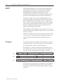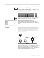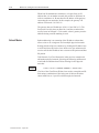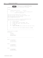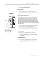
1
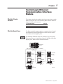
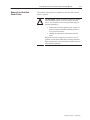
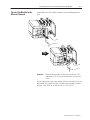
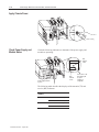
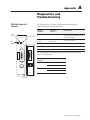
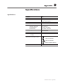
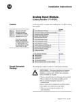
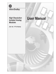
Allen-Bradley ControlLogix Ethernet Communication Interface Module User Manual (Cat. No. 1756-ENET) File Name: AB_EtherNetControlLogix_1756_ENET_user_D897 Important User Information Solid state equipment has operational characteristics differing from those of electromechanical equipment. “Safety Guidelines for the Application, Installation and Maintenance of Solid State Controls” (Publication SGI-1.1) describes some important differences between solid state equipment and hard–wired electromechanical devices. Because of this difference, and also because of the wide variety of uses for solid state equipment, all persons responsible for applying this equipment must satisfy themselves that each intended application of this equipment is acceptable. In no event will the Allen-Bradley Company be responsible or liable for indirect or consequential damages resulting from the use or application of this equipment. The examples and diagrams in this manual are included solely for illustrative purposes. Because of the many variables and requirements associated with any particular installation, the Allen-Bradley Company cannot assume responsibility or liability for actual use based on the examples and diagrams. No patent liability is assumed by Allen-Bradley Company with respect to use of information, circuits, equipment, or software described in this manual. Reproduction of the contents of this manual, in whole or in part, without written permission of the Allen-Bradley Company is prohibited. Throughout this manual we use notes to make you aware of safety considerations. ! ATTENTION: Identifies information about practices or circumstances that can lead to personal injury or death, property damage, or economic loss. Attentions help you: • identify a hazard • avoid the hazard • recognize the consequences Important: Identifies information that is especially important for successful application and understanding of the product. Ethernet is a registered trademark of Digital Equipment Corporation, Intel and Xerox Corporation. Microsoft is a registered trademark of Microsoft Corporation. Windows, Windows 95 and Windows NT are trademarks of Microsoft Corporation. ControlLogix and Data Highway Plus are trademarks of the Allen-Bradley Company, Inc. Table of Contents About this User Manual Preface What this Preface Contains . . . . . . . . . . . . . . . . . . . . . . . . . . . . . Who Should Use this Manual . . . . . . . . . . . . . . . . . . . . . . . . . . . . Purpose of This Manual . . . . . . . . . . . . . . . . . . . . . . . . . . . . . . . . Conventions and Related Terms . . . . . . . . . . . . . . . . . . . . . . . . . . Related Terms . . . . . . . . . . . . . . . . . . . . . . . . . . . . . . . . . . . . . Related Products and Documentation . . . . . . . . . . . . . . . . . . . . . . Rockwell Automation Support . . . . . . . . . . . . . . . . . . . . . . . . . . . . Local Product Support . . . . . . . . . . . . . . . . . . . . . . . . . . . . . . . Technical Product Assistance . . . . . . . . . . . . . . . . . . . . . . . . . . Your Questions or Comments on this Manual . . . . . . . . . . . . . . . ControlLogix Ethernet Communication Interface Module Chapter 1 Install the ControlLogix Ethernet Communication Interface Module Chapter 2 What this Chapter Contains . . . . . . . . . . . . . . . . . . . . . . . . . . . . . What the Module Does . . . . . . . . . . . . . . . . . . . . . . . . . . . . . . . . . Module Features . . . . . . . . . . . . . . . . . . . . . . . . . . . . . . . . . . . . . Removal and Insertion Under Power . . . . . . . . . . . . . . . . . . . . . . . What this Chapter Contains . . . . . . . . . . . . . . . . . . . . . . . . . . . . . Compliance to European Union Directives . . . . . . . . . . . . . . . . . . . . . . . . . . . EMC Directive . . . . . . . . . . . . . . . . . . . . . . . . . . . . . . . . . . . . . Low Voltage Directive . . . . . . . . . . . . . . . . . . . . . . . . . . . . . . . . Prevent Electrostatic Discharge . . . . . . . . . . . . . . . . . . . . . . . . . . Removal and Insertion Under Power . . . . . . . . . . . . . . . . . . . . . . . Prepare the Chassis for Module Installation . . . . . . . . . . . . . . . . . . Install or Remove the Module . . . . . . . . . . . . . . . . . . . . . . . . . . . . Determine Module Slot Location . . . . . . . . . . . . . . . . . . . . . . . . Install the Module . . . . . . . . . . . . . . . . . . . . . . . . . . . . . . . . . . Remove or Replace the Module (when applicable) . . . . . . . . . . . Wire the Ethernet Connector . . . . . . . . . . . . . . . . . . . . . . . . . . . . . Connect the Module to the Ethernet Network . . . . . . . . . . . . . . . . . Apply Chassis Power . . . . . . . . . . . . . . . . . . . . . . . . . . . . . . . . . . Check Power Supply and Module Status . . . . . . . . . . . . . . . . . . . . Configure the Ethernet Module . . . . . . . . . . . . . . . . . . . . . . . . . . . Understand CSA Hazardous Location Approval . . . . . . . . . . . . . P–1 P–1 P–1 P–2 P–3 P–4 P–4 P–4 P–4 P–4 1–1 1–2 1–3 1–4 2–1 2–1 2–1 2–1 2–3 2–3 2–3 2–4 2–4 2–5 2–6 2–7 2–8 2–9 2–9 2–10 2–11 Publication 1756-6.5.1 – August 1997 ii Before You Configure Your Ethernet Module Chapter 3 Configure Your Ethernet Module Chapter 4 Diagnostics and Troubleshooting Specifications What this Chapter Contains . . . . . . . . . . . . . . . . . . . . . . . . . . . . . Ethernet . . . . . . . . . . . . . . . . . . . . . . . . . . . . . . . . . . . . . . . . . . . Transmission Control Protocol/Internet Protocol (TCP/IP) . . . . . . . . BOOTP . . . . . . . . . . . . . . . . . . . . . . . . . . . . . . . . . . . . . . . . . . . . IP Address . . . . . . . . . . . . . . . . . . . . . . . . . . . . . . . . . . . . . . . . . Gateways . . . . . . . . . . . . . . . . . . . . . . . . . . . . . . . . . . . . . . . . . . Subnet Masks . . . . . . . . . . . . . . . . . . . . . . . . . . . . . . . . . . . . . . . Simple Network Management Protocol (SNMP) . . . . . . . . . . . . . . . What this Chapter Contains . . . . . . . . . . . . . . . . . . . . . . . . . . . . . Use BOOTP to Configure the Module . . . . . . . . . . . . . . . . . . . . . . Enter IP Address . . . . . . . . . . . . . . . . . . . . . . . . . . . . . . . . . . . Enter Ethernet Hardware Address . . . . . . . . . . . . . . . . . . . . . . . Enter Subnet Mask . . . . . . . . . . . . . . . . . . . . . . . . . . . . . . . . . Enter Gateway Address . . . . . . . . . . . . . . . . . . . . . . . . . . . . . . Use the ControlLogix Gateway Configuration Software to Configure the Module . . . . . . . . . . . . . . . . . . . . . . . . . . . . . . . . . . . . . . . Set an IP Address . . . . . . . . . . . . . . . . . . . . . . . . . . . . . . . . . . Select a Subnet Mask . . . . . . . . . . . . . . . . . . . . . . . . . . . . . . . Assign a Gateway Address . . . . . . . . . . . . . . . . . . . . . . . . . . . . Disable BOOTP . . . . . . . . . . . . . . . . . . . . . . . . . . . . . . . . . . . . 4–1 4–1 4–1 4–1 4–2 4–2 4–2 4–2 4–3 4–4 4–5 Appendix A What this Appendix Contains . . . . . . . . . . . . . . . . . . . . . . . . . . . . . . . . . . . . . . . . A–1 Appendix B Specifications . . . . . . . . . . . . . . . . . . . . . . . . . . . . . . . . . . . . . . . Publication 1756-6.5.1 – August 1997 3–1 3–1 3–1 3–2 3–2 3–3 3–4 3–5 B–1 Preface P–1 What this Preface Contains This preface describes how to use this manual. The following table describes what this preface contains and its location. For information about Who should use this manual Purpose of this manual Conventions and related terms Related products and documentation Rockwell Automation support Who Should Use this Manual See page P–1 P–1 P–2 P–4 P–4 We assume you have a good understanding of Ethernet and the (TCP/IP) protocol. For More Information... Purpose of This Manual Preface This user manual contains a brief description of Ethernet and TCP/IP in Chapter 2. For detailed information on TCP/IP protocol and networking in general, see the following publications: • Comer, Douglas E. Internetworking with TCP-IP, Volume 1: Protocols and Architecture, 2nd ed. Englewood Cliffs, N.J.: Prentice-Hall, 1995. ISBN 0-13-216987-8. • Tanenbaum, Andrew S. Computer Networks, 2nd ed. Englewood Cliffs, N.J.: Prentice-Hall, 1989. ISBN 0-13-162959-X. This manual describes how to understand, configure and troubleshoot your ControlLogix Ethernet communication module. Chapter 1 About this User Manual Chapter 2 Install the Module The ControlLogix Ethernet Module Appendix B Appendix A Chapter 4 Chapter 3 Specifications Troubleshoot the Module Configure the Module Before You Configure Your Module Publication 1756-6.5.1 – August 1997 P–2 Preface Conventions and Related Terms This manual uses the following conventions: This icon: Calls attention to: helpful, time-saving information Tip an example Example For More Information... Publication 1756-6.5.1 – August 1997 additional information in the publication referenced Preface P–3 Related Terms This term: Means: BOOTP low level protocol that provides communications to other nodes on a TCP/IP network an internetwork node between two similar communication subnets where protocol translation is minimal software that provides general module, diagnostic and configuration information for the ControlLogix modules. It also sets or changes the configuration of Ethernet or DHRIO modules and saves and restores configuration data. 1756-ENET module a logical communication path Data Highway Plus – A-B’s proprietary token pass communications protocol for peer to peer communications a physical layer standard using Carrier Sense Multiple Access with Collision Detection (CSMA/CD) methods bridge ControlLogix Gateway Configuration Software communication module connection DH+TM Ethernet Ethernet network a local area network designed for the high-speed exchange of information between computers and related devices gateway a module or set of modules that allows communications between nodes on dissimilar networks 32-bit identification for each node on Internet Protocol network LED indicator 1756-ENET module a six-bit number used to uniquely identify any module on the local and extended ControlLogix backplane a physical and logical collection of application modules sharing a common power supply and backplane for module to module communication IP address indicator module module address rack RIUP SNMP subnet mask TCP/IP transaction transfer remove and insert under power Simple Network Management Protocol – a standard for network management within TCP/IP an extension of the IP address that allows a site to use a single net ID for multiple networks Internet protocol suite (Transmission Control Protocol/Internet Protocol) an exchange of request and data and response and data to send a message to the next destination Publication 1756-6.5.1 – August 1997 P–4 Preface Related Products and Documentation The following table lists related ControlLogix products and documentation: Cat. number: Document title: Pub. number: 1756-ENET 1756-5.3 1756-GTWY 1756-DHRIO 1756-DHRIO 1756-CNB/R 1756–CNB/R Ethernet Communication Interface Module Installation Instructions ControlLogix Gateway Configuration Software Quick Start Data Highway Plus Communication Interface Module Installation Instructions Data Highway Plus Communication Interface Module User Manual ControlNet Bridge Module Installation Instructions ControlNet Bridge Module User Manual 1756-10.2 1756-5.4 1756-6.5.2 1756-5.32 1756-6.5.3 If you need more information on these products, contact your local Allen-Bradley integrator or sales office for assistance. For more information on the documentation, refer to the Allen-Bradley Publication Index, publication SD499. Rockwell Automation Support Rockwell Automation offers support services worldwide, with over 75 sales/support offices, 512 authorized distributors and 260 authorized systems integrators located throughout the United States alone, plus Rockwell Automation representatives in every major country in the world. Local Product Support Contact your local Rockwell Automation representative for: • sales and order support • product technical training • warranty support • support service agreements Technical Product Assistance If you need to contact Rockwell Automation for technical assistance, please review the troubleshooting information in Appendix A first. If the problem persists, then call your local Rockwell Automation representative. Your Questions or Comments on this Manual If you find a problem with this manual, please notify us of it on the enclosed Publication Problem Report. Publication 1756-6.5.1 – August 1997 Chapter 1 ControlLogix Ethernet Communication Interface Module What this Chapter Contains This chapter describes the module and what you must know and do before you begin to use it. The following table describes what this chapter contains and its location. For information about What the module does Module features Removal and insertion under power What the Module Does See page 1–1 1–2 1–3 The Ethernet module supports gateway communication of control and information data through Ethernet to other networks such as ControlNet and Data Highway Plus. Example The following illustration shows an example of a typical system. This system uses one ControlLogix Gateway linking existing Data Highway Plus, Ethernet and ControlNet networks. ControlLogix Gateway Data Highway Plus ControlNet Ethernet PLC-5 Processor Ethernet PLC-5 Processor ControlNet PLC-5 Processor PC with RSLinx Software PC with RSLinx Software PC with RSLinx Software SLC Processor 20901–M Publication 1756-6.5.1 – August 1997 1–2 ControlLogix Ethernet Communication Interface Module Module Features Backplane Connector Use the following illustration to identify the external features of the Ethernet module. Product Label Indicators <•••> ETHERNET Front Panel Front Panel RXD TXD OK Door and label AUI Ethernet Connector Ethernet Address AUI 10BT Ethernet Connector 10 BASET 1756-ENET Side View Front View Other module features are: • supports AUI and 10 Base-T media • uses standard TCP/IP protocol • supports gateway communication to and from other modules in the same chassis • no limit on number of modules per chassis • remove and insert under power • RSLinxTM Software Support Important: Publication 1756-6.5.1 – August 1997 This module does not support Ethernet to Ethernet bridging. ControlLogix Ethernet Communication Interface Module Removal and Insertion Under Power 1–3 This module is designed to be installed or removed while chassis power is applied. ! ATTENTION: When you insert or remove a module while backplane power is on, an electrical arc may occur. An electrical arc can cause personal injury or property damage by: • sending an erroneous signal to your system’s actuators causing unintended machine motion or loss of process control. • causing an explosion in a hazardous environment. Repeated electrical arcing causes excessive wear to contacts on both the module and its mating connector. Worn contacts may create electrical resistance that can affect module operation. Publication 1756-6.5.1 – August 1997 1–4 ControlLogix Ethernet Communication Interface Module Notes Publication 1756-6.5.1 – August 1997 Chapter 2 Install the ControlLogix Ethernet Communication Interface Module What this Chapter Contains This chapter describes how to install the module. The following table describes what this chapter contains and its location. For information about Compliance to European Union Directives Electrostatic discharge Removing and inserting the module under power Preparing the Chassis for Module Installation Installing, Removing or Replacing the Module Wiring the Ethernet Connector Applying Chassis Power Checking Power Supply and Module Status CSA Hazardous Location Approval Compliance to European Union Directives See page 2–1 2–2 2–2 2–2 2–3 2–6 2–8 2–8 2–9 This product has the CE mark and is approved for installation within the European Union and EEA regions. It has been designed and tested to meet the following directives. EMC Directive This product is tested to meet Council Directive 89/336/EEC Electromagnetic Compatibility (EMC) and the following standards, in whole or in part, documented in a technical construction file: • EN 50081-2EMC – Generic Emission Standard, Part 2 – Industrial Environment • EN 50082-2EMC – Generic Immunity Standard, Part 2 – Industrial Environment This product is intended for use in an industrial environment. Low Voltage Directive This product is tested to meet Council Directive 73/23/EEC Low Voltage, by applying the safety requirements of EN 61131–2 Programmable Controllers, Part 2 – Equipment Requirements and Tests. For specific information required by EN 61131-2, see the appropriate sections in this publication, as well as the following Allen-Bradley publications: • Industrial Automation Wiring and Grounding Guidelines For Noise Immunity, publication 1770-4.1 • Automation Systems Catalog, publication B112 This equipment is classified as open equipment and must be installed (mounted) in an enclosure during operation as a means of providing safety protection. Publication 1756-6.5.1 – August 1997 2–2 ControlLogix Ethernet Communication Interface Module Prevent Electrostatic Discharge The Ethernet module is sensitive to electrostatic discharge. ! ATTENTION: Electrostatic discharge can damage integrated circuits or semiconductors if you touch backplane connector pins. Follow these guidelines when you handle the module: • Touch a grounded object to discharge static potential • Wear an approved wrist-strap grounding device • Do not touch the backplane connector or connector pins • Do not touch circuit components inside the module • If available, use a static-safe work station • When not in use, keep the module in its static-shield bag Removal and Insertion Under Power This module is designed to be installed or removed while chassis power is applied. ! ATTENTION: When you insert or remove a module while backplane power is on, an electrical arc may occur. An electrical arc can cause personal injury or property damage by: • sending an erroneous signal to your system’s actuators causing unintended machine motion or loss of process control. • causing an explosion in a hazardous environment. Repeated electrical arcing causes excessive wear to contacts on both the module and its mating connector. Worn contacts may create electrical resistance that can affect module operation. Prepare the Chassis for Module Installation Before you install the Ethernet module, you must install and connect a ControlLogix chassis and power supply. To install these products, refer to the installation instructions you received with them. Chassis Power supply 20805–M Publication 1756-6.5.1 – August 1997 ControlLogix Ethernet Communication Interface Module Install or Remove the Module 2–3 This module is designed to be installed or removed while chassis power is applied. ! ATTENTION: When you insert or remove a module while backplane power is on, an electrical arc may occur. An electrical arc can cause personal injury or property damage by: • sending an erroneous signal to your system’s field devices causing unintended machine motion or loss of process control. • causing an explosion in a hazardous environment. Repeated electrical arcing causes excessive wear to contacts on both the module and its mating connector. Worn contacts may create electrical resistance that can affect module operation. Determine Module Slot Location This example shows chassis slot numbering in a 4-slot chassis. Slot 0 is the first slot and is always located to the right of the power supply. You can use any size ControlLogix chassis and install the module in any slot. Slot 0 Slot 2 Slot 1 Slot 3 Power Supply Chassis You can use multiple Ethernet modules in the same chassis. Publication 1756-6.5.1 – August 1997 2–4 ControlLogix Ethernet Communication Interface Module Install the Module 1 Align the circuit board with top and bottom guides in the chassis. Circuit board 2 Slide the module into the chassis. Make sure the module properly connects to the chassis backplane. 3 The module is fully installed when it is flush with the power supply or other installed modules. Publication 1756-6.5.1 – August 1997 ControlLogix Ethernet Communication Interface Module 2–5 Remove or Replace the Module (when applicable) 1 Push on upper and lower module tabs to disengage them. 2 Slide module out of chassis. If you are replacing an existing Ethernet module with an another Ethernet module, and you want to resume identical system operation, you must install the new Ethernet module in the same slot. Publication 1756-6.5.1 – August 1997 2–6 ControlLogix Ethernet Communication Interface Module Wire the Ethernet Connector Use either an AUI or an RJ45 connector to connect to the Ethernet network. Wire the appropriate connector according to the following illustrations: Protective Ground 1–Ctrl IN Ckt Shield 2–Ctrl IN CKT A 3–Data OUT Ckt A 4–Data IN Ckt Shield 5–Data IN Ckt A 6–Voltage Comm 7–Ctrl OUT Ckt A 8–Ctrl OUT Ckt Shield 9–Ctrl IN Ckt B 10–Data OUT Ckt B 11–Data OUT Ckt B 12–Data OUT Ckt B 13–Voltage Plus 14–Voltage Shield 15–Ctrl OUT Ckt B AUI Publication 1756-6.5.1 – August 1997 1 2 3 4 5 6 7 8 TD+ TD– RD+ NC NC RD– NC NC 8 1 RJ 45 ControlLogix Ethernet Communication Interface Module Connect the Module to the Ethernet Network 2–7 Attach either the AUI or RJ45 connector to the matching Ethernet port: OR Important: The maximum number of ASA connections per TCP connection is 32. If you exceed this limit, an error will occur. If your application requires the module door to be closed, use one of the custom AUI connector cables available in two lengths: 2 meters (cat. no. 1756-TC02) or 15 meters (cat. no. 1756-TC15). Publication 1756-6.5.1 – August 1997 2–8 ControlLogix Ethernet Communication Interface Module Apply Chassis Power ON POWER OFF Check Power Supply and Module Status Check the following indicators to determine if the power supply and module are operating: <•••> ETHERNET RXD TXD RXD indicator is OFF Power supply indicator is green TXD indicator is OFF OK OK indicator is red then flashing red (or green if module is configured) The following table describes the displays of the transmit (TX) and receive (RX) indicators: If this indicator: is: the module is: TXD Green Transmitting data Off Not active Green Receiving data Off Not active RXD Publication 1756-6.5.1 – August 1997 ControlLogix Ethernet Communication Interface Module 2–9 Understand CSA Hazardous Location Approval CSA Hazardous Location Approval CSA certifies products for general use as well as for use in hazardous locations. Actual CSA certification is indicated by the product label as shown below, and not by statements in any user documentation. Example of the CSA certification product label To comply with CSA certification for use in hazardous locations, the following information becomes a part of the product literature for CSA-certified Allen-Bradley industrial control products. • This equipment is suitable for use in Class I, Division 2, Groups A, B, C, D, or non-hazardous locations only. • The products having the appropriate CSA markings (that is, Class I Division 2, Groups A, B, C, D), are certified for use in other equipment where the suitability of combination (that is, application or use) is determined by the CSA or the local inspection office having jurisdiction. Important: Due to the modular nature of a PLC control system, the product with the highest temperature rating determines the overall temperature code rating of a PLC control system in a Class I, Division 2 location. The temperature code rating is marked on the product label as shown. Temperature code rating Look for temperature code rating here The following warnings apply to products having CSA certification for use in hazardous locations. ATTENTION: Explosion hazard — • Substitution of components may impair suitability for Class I, Division 2. ! • Do not replace components unless power has been switched off or the area is known to be non-hazardous. • Do not disconnect equipment e uipment unless power has been switched off or the area is known to be non-hazardous. • Do not disconnect connectors unless power has been switched off or the area is known to be non-hazardous. Secure any user-supplied connectors that mate to external circuits on an Allen-Bradley product using screws, sliding latches, threaded connectors, or other means such that any connection can withstand a 15 Newton (3.4 lb.) separating force applied for a minimum of one minute. PLC is a registered trademark of Allen-Bradley Company, Inc. CSA logo is a registered trademark of the Canadian Standards Association. Publication 1756-6.5.1 – August 1997 2–10 ControlLogix Ethernet Communication Interface Module Approbation d’utilisation dans des emplacements dangereux par la CSA La CSA certifie les produits d’utilisation générale aussi bien que ceux qui s’utilisent dans des emplacement dangereux. La certification CSA en vigueur est indiquée par l’étiquette du produit et non par des affirm dans la documentation à l’usage des utilisateurs. Exemple d’étiquette de certification d’un produit par la CSA Pour satisfaire à la certification de la CSA dans des endroits dangereux, les informations suivantes font partie intégrante de la documentation des produits industriels de contrôle Allen-Bradley certifiés par la CSA. • Cet équipement convient à l’utilisation dans des emplacements de Classe I, Division 2, Groupes A, B, C, D, ou ne convient qu’à l’utilisation dans des endroits non dangereux. • Les produits portant le marquage approprié de la CSA (c’est à dire, Classe I, Division 2, Groupes A, B, C, D) sont certifiés à l’utilisation pour d’autres équipements où la convenance de combinaison (application ou utilisation) est déterminée par la CSA ou le bureau local d’inspection qualifié. Important: Par suite de la nature modulaire du système de contrôle PLC, le produit ayant le taux le plus élevé de température détermine le taux d’ensemble du code de température du système de contrôle d’un PLC dans un emplacement de Classe 1, Division 2. Le taux du code de température est indiqué sur l’étiquette du produit. Taux du code de température Le taux du code de température est indiqué ici Les avertissements suivants s’appliquent aux produits ayant la certification CSA pour leur utilisation dans d emplacements dangereux. AVERTISSEMENT: Risque d’explosion — • La substitution de composants peut rendre ce matériel inacceptable pour lesemplacements de Classe I, Division 2. ! • Couper le courant ou s’assurer quel’emplacement est désigné non dangereux avant de remplacer lescomposants. • Avant de débrancher l’équipement, couper le courant ou s’assurer que l’emplacemen est désigné non dangereux. • Avant de débrancher les connecteurs, couper le courant ou s’assurer que l’emplacement est reconnu non dangereux. Attacher tous connecteurs fournis par l’utilisateur et reliés aux circuits externes d’un appareil Allen-Bradley à l ’aide de vis, loquets coulissants, connecteurs filetés ou autres moyens permettant aux connexions de résister à une force de séparation de 15 newtons (3,4 lb. - 1,5 kg) appliquée pendant au moins une minute. Le sigle CSA est la marque déposée de l’Association des Standards pour le Canada. PLC est une marque déposée de Allen-Bradley Company, Inc. Publication 1756-6.5.1 – August 1997 Chapter 3 Before You Configure Your Ethernet Module What this Chapter Contains This chapter describes what you must know before you configure your Ethernet module. The following table describes what this chapter contains and its location. For information about Ethernet Transmission Control Protocol/Internet Protocol (TCP/IP) BOOTP IP Address Gateways Subnet Masks Simple Network Management Protocol (SNMP) See page 3–1 3–1 3–2 3–2 3–3 3–4 3–5 Ethernet On the most basic level, Ethernet is a wire or cable that connects computers and peripheral devices so that they can communicate. The actual wire used for a network is called the network medium. Transmission Control Protocol/Internet Protocol (TCP/IP) Transmission Control Protocol/Internet Protocol (TCP/IP) is a transport-layer protocol (TCP) and a network-layer protocol (IP) commonly used for communication within networks and across internetworks. The Ethernet module uses TCP/IP for Ethernet communication. For more information about TCP/IP and internetworking, refer to: Internetworking with TCP/IP – Vol. 1, 2nd ed., by Douglas E. Comer ISBN 0-13-216987-8 The Ethernet Management Guide —Keeping The Link ISBN 0-07-046320-4 An Introduction to TCP/IP ISBN 3-540-96651-X Computer Networks by Andrew S. Tanenbaum ISBN 0-13-162959-X Publication 1756-6.5.1 – August 1997 3–2 Before You Configure Your Ethernet Module BOOTP BOOTP (Bootstrap protocol) is a low-level protocol that provides configurations to other nodes on a TCP/IP network with DOS, Microsoft Windows, Windows NT, Windows 95, VMS and HP-UNIX platforms. BOOTP configuration files let you automatically assign IP addresses to the Ethernet module. You can also obtain subnet masks and gateway addresses from BOOTP. The Ethernet module factory default is BOOTP enabled. Upon powerup, the module sends a message to the BOOTP server on the network with its hardware address. The server is a computer (PC, VAX, or UNIX system) that has BOOTP server software installed. The server compares that hardware address to those in its look-up table in the configuration file and sends a message back to the module with the appropriate IP address. With all hardware and IP addresses in one location, you can easily change IP addresses in the BOOTP configuration file if your network needs to be changed. If BOOTP is disabled (or there is no BOOTP server on the network), you can use the ControlLogix Gateway Configuration Software to configure Ethernet from another module installed in the same chassis. IP Address The IP address identifies each node on the IP network (or system of connected networks). Each TCP/IP node on a network (including the Ethernet module) must have a unique IP address. The IP address is 32 bits long and has a net ID part and a host ID part. Each network is a Class A, Class B, or Class C network. The class of a network determines how an IP address is formatted. 0 Class A Class B 1 1 0 1 1 1 0 16 net ID 0 0 Class C 8 1 24 host ID 8 16 24 net ID 31 host ID 8 0 31 16 net ID 24 31 host ID Each node on the same physical network must have an IP address of the same class and must have the same net ID. Each node on the same network must have a different host ID thus giving it a unique IP address. Publication 1756-6.5.1 – August 1997 Before You Configure Your Ethernet Module Example 3–3 IP addresses are written as four decimal integers (0-255) separated by periods where each integer gives the value of one byte of the IP address. For example, the 32-bit IP address: 00000011 00000000 00000000 00000001 is written as 3.0.0.1. You can distinguish the class of an IP address from the first integer in its dotted-decimal IP address as follows: Range of first integer 0 -127 128 -191 Tip For More Information... Gateways Class A B Range of first integer 192 - 223 224 - 255 Class C other Contact your network administrator or the Network Information Center for a unique IP address to assign to your module. For more information on Internet addressing, see Comer, Douglas E; Internetworking with TCP-IP, Volume 1: Protocols and Architecture; Englewood Cliffs, N.J.: Prentice-Hall, 1990. A gateway connects individual physical networks into a system of networks. When a node needs to communicate with a node on another network, a gateway transfers the data between the two networks. The following figure shows gateway G connecting Network 1 with Network 2. A 128.1.0.1 Network 1 128.1.0.2 G B 128.2.0.1 128.2.0.3 C 128.2.0.2 Network 2 When host B with IP address 128.2.0.1 communicates with host C, it knows from C’s IP address that C is on the same network. In an Ethernet environment, B can then resolve C’s IP address to a MAC address (via ARP) and communicate with C directly. Publication 1756-6.5.1 – August 1997 3–4 Before You Configure Your Ethernet Module When host B communicates with host A, it knows from A’s IP address that A is on another network (the net IDs are different). In order to send data to A, B must have the IP address of the gateway connecting the two networks. In this example, the gateway’s IP address on Network 2 is 128.2.0.3. The gateway has two IP addresses (128.1.0.2 and 128.2.0.3). The first must be used by hosts on Network 1 and the second must be used by hosts on Network 2. To be usable, a host’s gateway must be addressed using a net ID matching its own. Subnet Masks Subnet addressing is an extension of the IP address scheme that allows a site to use a single net ID for multiple physical networks. Routing outside of the site continues by dividing the IP address into a net ID and a host ID via the class. Inside a site, the subnet mask is used to redivide the IP address into a custom net ID portion and host ID portion. Take Network 2 (a Class B network) in the previous example and add another physical network. Selecting the following subnet mask would add two additional net ID bits allowing for four physical networks: Example 11111111 11111111 11000000 00000000 = 255.255.192.0 Two bits of the Class B host ID have been used to extend the net ID. Each unique combination of bits in the part of the host ID where subnet mask bits are 1 specifies a different physical network. Publication 1756-6.5.1 – August 1997 Before You Configure Your Ethernet Module 3–5 The new configuration is: A 128.1.0.1 Network 1 128.1.0.2 G B 128.2.64.3 C 128.2.64.1 128.2.64.2 Network 2.1 G2 D 128.2.128.1 128.2.128.3 E 128.2.128.2 Network 2.2 A second network with Hosts D and E has been added. Gateway G2 connects Network 2.1 with Network 2.2. Hosts D and E will use Gateway G2 to communicate with hosts not on Network 2.2. Hosts B and C will use Gateway G to communicate with hosts not on Network 2.1. When B is communicating with D, G (the configured Gateway for B) will route the data from B to D through G2. Simple Network Management Protocol (SNMP) Simple Network Management Protocol (SNMP) is a standard for network management within TCP/IP environments. This lets client applications monitor and manage network information on host computers and gateways. Network administrators run programs that use SNMP to manage their networks. The ethernet module supports the SNMP protocol at the MIB II level. Publication 1756-6.5.1 – August 1997 3–6 Before You Configure Your Ethernet Module Notes Publication 1756-6.5.1 – August 1997 Chapter 4 Configure the Ethernet Module What this Chapter Contains This chapter describes how to configure the Ethernet module. The following table describes what this chapter contains and its location. For information about Use BOOTP to configure the module Use the ControlLogix Gateway Configuration Software to configure the module Use BOOTP to Configure the Module See page 4–1 4–4 The Ethernet module factory default is BOOTP enabled. If BOOTP is disabled (or there is no BOOTP server on the network), you must use the ControlLogix Gateway Configuration Software to enter/change the IP address, subnet mask and gateway address for your Ethernet module. Skip to the next section to use the software to configure your module. Publication 1756-6.5.1 – August 1997 4–2 Configure the Ethernet Module Example The following text is an example BOOTP tab file: # Example /etc/bootptab: database for bootp server (/etc/bootpd). # # Format: # nodename:tag=value:tag=value: . . . .:tag=value # # first field – – nodename (hostname) of terminal followed by colon # (should be full domain name) # # Blank lines and lines beginning with ’#’ are ignored. # Make sure you include a colon and a backslash to continue a line. # Don’t put any spaces in the tag–value string. # The ht tag MUST precede the ha tag. # # The options below are specified as tag=value and delimited by colons # These are the options used by the 1756-ENET module: # # gw – – gateway IP address # ha – – hardware address (link level address) (hex) # ht – – hardware type (either) (must precede the ha tag) # ip – – IP address # sm – – network subnet mask # tc – – template for common defaults (should be the first option listed) # # vm – – vendor magic cookie selector (MUST be rfc1048 for 1756-ENET) # #-––––––––––––––––––––––––––––––––––––––––––––––––––––––––––––––––––––––––––––– # default values for 1756-ENET icp.defaults:\ ht=ether:\ vm=rfc1048:\ sm=255.255.254.0:\ gw=130.151.132.1 #-––––––––––––––––––––––––––––––––––––––––––––––––––––––––––––––––––––––––––––– zappa0:\ tc=icp.defaults:\ ha=0000bc03404f:\ ip=130.151.132.121 zappa1:\ tc=icp.defaults:\ ha=0000bc034073:\ ip=130.151.132.122 zappa2:\ tc=icp.defaults:\ ha=0000bc034022:\ ip=130.151.132.123 Publication 1756-6.5.1 – August 1997 Configure the Ethernet Module 4–3 To use BOOTP to configure the module: 1. Access and open the bootptab file. Enter IP Address 2. Use a text editor to enter the IP address of your module. If you need more information on setting IP addresses, refer to page 3–2. <•••> ETHERNET Ethernet Address Enter Ethernet Hardware Address OK 00:00:BC:03:41:63 Ethernet Address RXD TXD AUI When using the BOOTP protocol, you must enter the Ethernet hardware address of your module. Allen-Bradley assigns each Ethernet module a unique hardware address at the factory. The address is a 48-bit address that consists of six hexadecimal digits separated by dots. The address is printed on a label on the front of your Ethernet module as shown in the figure on the left. You cannot change this address. 10 BASET 1756-ENET Front View 00:00:BC:03:41:63 Ethernet Address 3. Use a text editor to enter the Ethernet hardware address of your module. You must enter all digits, including zeroes. If you ever change or replace this Ethernet module, you must enter the new Ethernet hardware address of the new module. Enter Subnet Mask 4. Continue using the text editor to enter the subnet mask: If you need more information on selecting subnet masks, refer to page 3–4. Enter Gateway Address 5. Continue using the text editor to enter the gateway address: If you need more information on assigning gateway addresses, refer to page 3–3. Publication 1756-6.5.1 – August 1997 4–4 Configure the Ethernet Module Use the ControlLogix Gateway Configuration Software to Configure the Module Use the ControlLogix Gateway Configuration Software to: • set an IP address • select a subnet mask • assign a gateway address • disable BOOTP The procedures in this section assume you have the software installed and open. For More Information... For more information on using the ControlLogix Gateway Configuration Software, refer to the ControlLogix Gateway Configuration Software Quick Start, publication 1756-10.2. Set an IP Address To set an IP address: 1. Select the Port Configuration tab. 2. Enter the appropriate IP address of the module in the IP Address field. Make sure your entry is in the form xxx.xxx.xxx.xxx where each xxx is a number between 0–255. If you need more information on setting IP addresses, refer to page 3–2. Publication 1756-6.5.1 – August 1997 Configure the Ethernet Module 4–5 Select a Subnet Mask To select a subnet mask: Enter the appropriate subnet mask of the module in the Subnet Mask field. Make sure your entry is in the form xxx.xxx.xxx.xxx where each xxx is a number between 0–255. If you need more information on selecting subnet masks, refer to page 3–4. Assign a Gateway Address To assign a gateway address: Enter the appropriate gateway address of the module in the Gateway Address field. Make sure your entry is in the form xxx.xxx.xxx.xxx where each xxx is a number between 0–255. If you need more information on assigning gateway addresses, refer to page 3–3. Disable BOOTP The Ethernet module factory default is BOOTP enabled. To configure the module manually, you must disable BOOTP. To disable BOOTP: 1. Click on the Bootp Enabled field to disable BOOTP. The X will disappear. 2. Click on Apply. If you need more information on BOOTP, refer to page 3–2. Publication 1756-6.5.1 – August 1997 4–6 Configure the Ethernet Module Notes Publication 1756-6.5.1 – August 1997 Index A applying power, chassis, 2–8 ASA connections, maximum, 2–7 audience, user manual, P–1 AUI, connector pinouts, 2–6 AUI connector cables, sizes, 2–7 ControlLogix Configuration Software, definition, P–3 ControlLogix Ethernet Module, installation, 2–1 ControlLogix Gateway Configuration Software related publication, 4–2 using, 4–2 conventions, P–2 B BOOTP definition, P–3 description, 3–2 disabling, 4–3 for configuration, 4–1 bridge, definition, P–3 bridging, Ethernet to Ethernet, 1–2 C cable sizes, AUI connector, 2–7 CE compliance, 2–1 mark, 2–1 chassis apply power, 2–8 Ethernet Module, 2–3 module location, 2–3 power supply, 2–2 prepare for installation, 2–2 slot numbering, 2–3 communication module, definition, P–3 compliance to European Union Directives, 2–1 CSA Hazardous Location Approval, 2–10 D Data Highway Plus, definition, P–3 DH+, definition, P–3 diagnostics chassis, 2–8 power supply, 2–8 diagnostics and troubleshooting, A–1 directives, European Union, 2–1 documentation, related, P–4 E Electrostatic Discharge, preventing, 2–2 EMC directive, 2–1 ENET, definition, P–3 ESD, preventing, 2–2 Ethernet definition, P–3 description, 3–1 network requirements, 4–1 connection, definition, P–3 Ethernet Connector pinouts, 2–6 wiring, 2–6 connector, pinouts, 2–6 Ethernet hardware address, 4–1 Control Logix, Ethernet Module, 1–1 Ethernet Module and ESD, 2–2 connecting to network, 2–7 description, 1–1 features, 1–2 preparing to install, 2–2 configuring the module, 4–1 ControlLogix, Gateway, system example, 1–1 Publication 1756-6.5.1 – August 1997 I–2 Index Ethernet module configuration, 4–1 specifications, B–1 Ethernet network definition, P–3 module connection, 2–7 Ethernet to Ethernet bridging, 1–2 European Union, directives, 2–1 European Union Directives, 2–1 example, system configuration, 1–1 G gateway definition, P–3 description, 3–3 examples, 3–3 gateway address assigning, 4–3 in BOOTP, 4–2 H hardware address, Ethernet, 4–1 I M manuals, related, P–4 maximum connections, ASA, 2–7 media, Ethernet, 4–1 module configuration, 4–1 connect to network, 2–7 connector pinouts, 2–6 definition, P–3 description, 1–1 diagnostics and troubleshooting, A–1 Ethernet hardware address, 4–1 features, 1–2 handling and care, 2–2 indicator status, A–1 installation, 2–1, 2–3 preparation, 2–2 installation procedure, 2–4 preventing ESD, 2–2 purpose, 1–1 removal procedure, 2–5 removing, 2–3 safety, 2–2 slot location, 2–3 specifications, B–1 status upon powerup, 2–8 module address, definition, P–3 module connector, pinouts, 2–6 indicator, definition, P–3 installation module, 2–1 power supply, 2–2 preparation, 2–2 installation procedure, module, 2–4 installing Ethernet Module, 2–1 module, 2–4 Internet Protocol address, description, 3–2 IP address definition, P–3 description, 3–2 example, 3–3 in BOOTP, 4–1 setting, 4–2 N network connector, pinouts, 2–6 P pinouts, Ethernet Connector, 2–6 power supply applying power, 2–8 installation, 2–2 status upon powerup, 2–8 procedure installation, 2–4 removing a module, 2–5 product support, P–4 products, related, P–4 Protocol, alternative, 3–1 L low voltage directive, 2–1 Publication 1756-6.5.1 – August 1997 publications, related, P–4 purpose, module, 1–1 Index R rack, definition, P–3 related products and documentation, P–4 related publications, P–1 TCP/IP, 3–1 related terms, P–3 Removal and Insertion Under Power attention, 1–3 feature, 1–3 removal procedure, module, 2–5 removing, module, 2–5 RIUP attention, 1–3 definition, P–3 feature, 1–3 RJ45, connector pinouts, 2–6 Rockwell Automation, support, P–4 S Simple Network Management Protocol, description, 3–5 slot location, module, 2–3 slot numbering, chassis, 2–3 SNMP definition, P–3 description, 3–5 specifications, module, B–1 Publication 1756-6.5.1 – August 1997 I–3 I–4 Index Notes subnet mask definition, P–3 description, 3–4 in BOOTP, 4–2 selecting, 4–3 system configuration, example, 1–1 T TCP/IP definition, P–3 description, 3–1 related publications, P–1, 3–1 transaction, definition, P–3 transfer, definition, P–3 Transmission Control Protocol/Internet Protocol, description, 3–1 troubleshooting, module, A–1 typical system configuration, 1–1 U user manual conventions, P–2 how to use, P–1 purpose, P–1 questions or comments, P–4 related terms, P–3 who should use, P–1 Publication 1756-6.5.1 – August 1997 Appendix A Diagnostics and Troubleshooting What this Appendix Contains TXD Indicator RXD Indicator <•••> ETHERNET RXD TXD The following table describes module health indicator displays, module status and recommended action: If the OK indicator is: then module status is: take this action: Off Not operating. Apply chassis power. Verify module is completely inserted into chassis and backplane. Red, then flashing red or green Performing powerup diagnostics. None, normal operation. Green Operating. None. Red flashing Not configured. Configure module (refer to Chapter 4) Red Unrecoverable fault. Repair or replace module. OK Indicator OK The following table describes the displays of the transmit (TX) and receive (RX) indicators: AUI If this indicator: is: the module is: TXD Green Transmitting data Off Not active Green Receiving data Off Not active 10 BASET RXD 1756-ENET Front View Publication 1756-6.5.1 – August 1997 Variable Content TTL:Chap A–2 Notes Publication XXXX-XX.X – April 1996 Appendix B Specifications Description Value Module Location any slot in the ControlLogix chassis Current Requirements 900mA @ +5V dc and 350mA @ 24 V dc from I/O chassis backplane Power Dissipation 13.13W maximum @ 5.0V dc Thermal Dissipation 17.2 BTU/hr maximum @ 5.0V dc Environmental Conditions: Operational Temperature Storage Temperature Relative Humidity Shock Unpackaged Vibration Unpackaged Conductors Wiring Category 0-60oC (32-140oF) -40 to 85oC (–40 to 185oF) 5-95% without condensation 30g operational 50g non-operational 5g from 10-150Hz 802.3 compliant – twisted pair or AUI 2 Agency Certification (when product or packaging is marked) Class I Div 2 Hazardous ÎÎÎ Î ÎÎ ÎÎ Class I Div 2 Hazardous marked for all applicable directives Installation Instructions Publication 1756-5.3 Publication 1756-6.5.1 – August 1997 Variable Content TTL:Chap B–2 Notes Publication XXXX-XX.X – April 1996 Allen-Bradley Publication Problem Report If you find a problem with our documentation, please complete and return this form. Pub. Name ControlLogix Ethernet Communication Interface Module Cat. No. 1756-ENET Check Problem(s) Type: Pub. No. 1756-6.5.1 Pub. Date August 1997 Part No. Describe Problem(s): 955126-69 Internal Use Only Technical Accuracy text Completeness procedure/step illustration definition info in manual example guideline feature (accessibility) explanation other What information is missing? illustration info not in manual Clarity What is unclear? Sequence What is not in the right order? Other Comments Use back for more comments. Your Name Location/Phone Return to: Technical Communication, Allen-Bradley Co., 1 Allen-Bradley Drive, Mayfield Hts., OH 44124 Publication ICCG-5.21-August 1995 Phone: (216)646-3166 FAX: (216)646-4320 PN 955107-82 PLEASE FASTEN HERE (DO NOT STAPLE) PLEASE FOLD HERE NO POSTAGE NECESSARY IF MAILED IN THE UNITED STATES BUSINESS REPLY MAIL FIRST-CLASS MAIL PERMIT NO. 18235 CLEVELAND OH POSTAGE WILL BE PAID BY THE ADDRESSEE 1 ALLEN BRADLEY DR MAYFIELD HEIGHTS OH 44124-9705 PLEASE REMOVE Other Comments 45 Allen-Bradley, a Rockwell Automation Business, has been helping its customers improve productivity and quality for more than 90 years. We design, manufacture and support a broad range of automation products worldwide. They include logic processors, power and motion control devices, operator interfaces, sensors and a variety of software. Rockwell is one of the world’s leading technology companies. Worldwide representation. Argentina • Australia • Austria • Bahrain • Belgium • Brazil • Bulgaria • Canada • Chile • China, PRC • Colombia • Costa Rica • Croatia • Cyprus • Czech Republic • Denmark • Ecuador • Egypt • El Salvador • Finland • France • Germany • Greece • Guatemala • Honduras • Hong Kong • Hungary • Iceland • India • Indonesia • Ireland • Israel • Italy • Jamaica • Japan • Jordan • Korea • Kuwait • Lebanon • Malaysia • Mexico • Netherlands • New Zealand • Norway • Pakistan • Peru • Philippines • Poland • Portugal • Puerto Rico • Qatar • Romania • Russia–CIS • Saudi Arabia • Singapore • Slovakia • Slovenia • South Africa, Republic • Spain • Sweden • Switzerland • Taiwan • Thailand • Turkey • United Arab Emirates • United Kingdom • United States • Uruguay • Venezuela • Yugoslavia Allen-Bradley Headquarters, 1201 South Second Street, Milwaukee, WI 53204 USA, Tel: (1) 414 382-2000 Fax: (1) 414 382-4444 Publication 1756-6.5.1 – August 1997 PN 955126-69 Copyright 1997 Allen-Bradley Company, Inc. Printed in USA