1
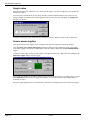
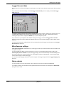
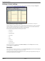
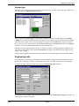
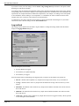
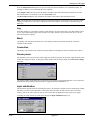
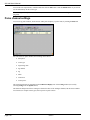
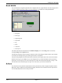
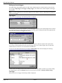
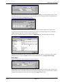
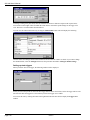
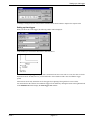
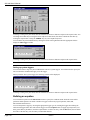
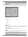
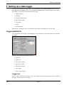
Setting up a data logger
5 Setting up a data logger
To enter new setup details for a logger, either select the New button in the Setwise Assistant window or choose
New (File menu) in the Setwise window. This will display the Setwise window containing default entries. Within
this window you can set and view the following for the logger:
• logger parameters
• run details
• analogue channel settings
• pulse channel settings
• event details
• actions
• status information.
When you have configured a setup, you can check the details before transmitting them to the SQ 1600.
Logger parameters
To set up parameters for the logger click the Logger tab. This will display current parameters that you can amend
as required:
These parameters fall into the following categories:
• logger text
• sample rates
• sensor power supplies
• logger time and date
• miscellaneous settings
• alarm outputs
• show on logger display.
Logger text
This is text that is associated with a logger. It is also the text that will be used to identify the set-up if it is stored in
the logger. You can enter up to 20 characters.
issue 1
page 5-1
SQ 1600 User’s Manual
Sample rates
Four separate sample rates, labelled A to D, can be set in the logger. You can then apply these rates to different
channels as required.
You can specify each sample rate in days, hours, minutes, seconds and milliseconds (in steps of 100 ms). To
change a sample rate, click the button at the right-hand end of the rate field. This will display the Sample rate
dialog box for the rate:
To change a setting in any time field, click the field then use the arrow buttons to adjust to the required value.
Sensor power supplies
Four separate sensor power supplies can be configured. You can then assign these to different channels.
Select the Check power supply while logging checkbox to make the logger monitor the sensor power supply
levels while logging. If they are not within tolerance when the reading is made, then an INVALID READING is
logged.
To change a sensor supply voltage, click the button at the right-hand end of the supply field. This will display the
Edit Sensor Supply dialog box for the supply:
You can enter the number of seconds for which the supply will be switched on before a reading is taken, or select
the Continuous checkbox to have the supply on all the time. You can also enter the output voltage supply, in
increments of 0.05 V.
The green wiring diagram shows the terminal block connections on the Squirrel that will be used for this supply.
page 5-2
issue 1
Setting up a data logger
Logger time and date
You can choose to set the time manually or synchronise it to the PC clock. The date format can also be chosen from
here.
If you want to set the time manually, click the Set logger time manually button to display the Current Logger
Time dialog box:
To change a setting in any time field, click the field then use the arrow buttons to adjust to the required value. You
can change the month and year using the arrows adjacent to their labels, then choose a different date either by
clicking the required date or using the ARROW keys on your computer keyboard.
If you want to use your computer’s time and date settings in the logger, click the Set logger time to PC time
button. The logger time will be updated (note that this may take a few seconds, and progress will be shown on the
status bar).
You can select the format in which the date will be stored and shown in the logger from the options in the Logger
date format drop-down list.
Miscellaneous settings
Lock Squirrel keyboard will disable the keys on the logger itself; only the meter function will be accessible from
the Squirrel keyboard.
You can configure the display to switch off when it is not in use, a feature that will help preserve battery life.
Switch display off after a minute will cause the logger display to turn off automatically when left unchanged for
60 seconds, otherwise it will stay on all the time. If the display switches off automatically, it will switch on again
when a further change is made on the logger.
You can choose the language that will be used for messages on the logger display from the Logger language dropdown list.
Alarm outputs
You can configure up to four alarm outputs. These can then be activated from within the Actions tab.
To configure an alarm, click the button at the right-hand end of the alarm field. This will display the Edit Alarm
dialog box for the alarm:
issue 1
page 5-3
SQ 1600 User’s Manual
You can enter a description that will be used to identify this alarm type, up to 20 alphanumeric characters. You can
also set the alarm to be latched (causing the alarm to continue until it is reset through either the Status tab or the
Squirrel control panel) or unlatched (causing the alarm to be reset as soon as the alarm condition is removed) by
selecting or deselecting the Latched checkbox. Alarm conditions are determined by equations defined in the
Actions tab.
The green wiring diagram shows the terminal block connections on the Squirrel that will be used for this alarm.
Show on logger display
This list shows all the channels that have been configured for the Squirrel, with a Display checkbox for each.
Select the checkbox to show the selected channel on the logger screen. This can be useful in auto scroll mode in the
logger.
Run details
To set options for the next run to be logged in the data logger, click the Run tab. This will display the current run
settings for the setup:
Run details fall into the following categories:
• run text
• run memory
• logging speed
• miscellaneous settings
• memory mode.
page 5-4
issue 1
Setting up a data logger
Run text
This is the text that is used to identify the run. Each run must have a unique text entry. You can enter up to 20
characters.
Run memory
From the Memory allocated to this run drop-down list, you can select the maximum memory capacity that will be
allowed for data recorded during this run. If you select No limit set, all the run data will be recorded regardless of
the required memory.
From the three memory lists, you can select the memory type that will be used to record log data. If you are using
the Change memory mode, you can select the order in which you want the memory to be filled. Note that these
lists are interactive. If you select a memory type from a list, that option will no longer be available in the lower
lists.
Logging speed
You can choose the appropriate option button to select either normal or fast mode.
The shortest logging interval available is 100 ms, and this is the shortest time that can be achieved between samples
of any given channel in normal mode. In fast mode, the logging interval setting is ignored and samples are taken as
rapidly as possible.
Fast mode will log a complete set of channels as often as possible at the rate of 24 samples every 200 ms (eg if
three channels are set to log, then each will be sampled eight times in each 200 ms). The real maximum rate that
can be achieved by the logger is dictated by the Firmware version (the internal logger software revision). Setwise
will determine this maximum rate while it communicates with the Squirrel.
When fast mode has been activated (by selecting the option button), Setwise will inform you of the number of
channels that can be logged in the 100 ms time frame:
Miscellaneous settings
Using the Mains rejection options, you can set the Squirrel to reject mains interface at either 50 Hz or 60 Hz
depending on your local mains supply. To disable mains rejection, select None; this will allow it to log faster, but it
may also lead to an increased risk of inaccuracies in the data.
You can set the Sync mode to either Synchronous or Asynchronous. When set to synchronous mode the logger
will attempt to keep a constant time between channel readings. In asynchronous mode no attempt is made to do
this, and therefore, logging can be faster.
Memory mode
Use the option buttons to select the required memory mode. Each option has a full description of its action.
issue 1
page 5-5
SQ 1600 User’s Manual
Analogue channel settings
You can set-up analogue channels, which measure voltage, current or resistance by clicking the Analogue tab:
Note that temperature sensor values are converted from either resistance (for thermistors) or voltage (for
thermocouples) into degrees Centigrade or Fahrenheit.
Analogue channels are set-up in groups of three, separated within the Analogue tab list by red lines (eg channels 1,
2 and 3). Note that the last group has only two channels. The sensor type you set on one channel will affect the
(range of different) sensor types available on the other two within the group.
For each of the 26 analogue channels, the following can be shown:
• description
• sensor type
• engineering units
• log method
• log
• block
• connection
• sensor power
• input stabilisation.
The actual items shown are determined in the Columns to Display area of the Config window (accessed by
selecting Config from the Options menu).
Description
This is the name that is assigned to the channel, (for example Room temperature) and will be stored and displayed
in the Squirrel, and also in the Squirrelwise and Filewise software
To change the description, double-click to highlight the current entry then type the required character string. You
can enter up to 20 characters for each channel.
page 5-6
issue 1
Setting up a data logger
Sensor type
This allows you to configure the input to match the chosen sensor type. To select a sensor and range, double-click
this field to display the Range Selection dialog box:
Click an option in the Sensor type list, and the ranges available for that sensor will be displayed in the Ranges
available list. The range selection determines the resolution of the readings as well as the maximum and minimum
values that can be logged. You can select the appropriate range then click the OK button to apply the selections.
If you want to remove a sensor selection, click the Un-set sensor button. The Sensor Type entry in the Analogue
tab will be returned to Not Set, and the channel will be made inoperative.
Although auto-range logging should always give a reading on a channel, if the logging speeds are high there may
not be time to change ranges. This will result in NO DATA being logged. This indicates that the logger has been
unable to take a reading.
The green wiring diagram shows the terminal block connections on the Squirrel that will be used for this channel.
Engineering units
This setting allows you to configure the channel so that the readings are displayed in units other than those of the
Sensor type. For example you may have a sensor that returns 0 to 1 Volt, which represents 0 to 100% humidity.
To change the setting, double-click this field to display the Engineering Units dialog box:
If you want to use the standard settings for the sensor type select the Use normal range settings option button. All
other selections will then be disabled.
issue 1
page 5-7
SQ 1600 User’s Manual
If you want to select your own settings, click the Use EU range settings below option button. The options within
the dialog box will then be available.
You can then enter the maximum and minimum reading values (the units will depend on the sensor types), with the
corresponding values to be shown in displays. These settings determine the information that will be included in any
exported file, for example when data is transferred to Squirrelwise. For example, if a reading of 3214 corresponds
to 212º Fahrenheit, while a reading of -58 corresponds to -11º Fahrenheit, the entries would be as shown in the
example. In this case, each entry will be shown to two decimal places.
A comparison of your entries with the previous settings is shown at the bottom of the dialog box. If you want to
return to the sensor’s default settings, click the Set to default button.
Log method
This setting tells the Squirrel how and when to log the channel. To change the setting, double-click this field to
display the Logging Method dialog box:
From this dialog box you can select:
• how the channels are logged
• how often they are updated internally
• how often they are logged.
Select the option button corresponding to the logging mode you require for this channel. The options are:
• Interval - channels will be updated every sample interval and put into memory every record interval
• Average - channels will be read every sample interval and then the average will be stored every record
interval
• Maximum - the channels will be checked every sample interval and the maximum value will be stored at
the record interval
• Minimum - the channels will be checked every sample interval and the minimum value will be stored at
the record interval.
• Action only - channels will be updated every sample interval but never logged to memory unless specified
to do so through an action definition.
page 5-8
issue 1
Setting up a data logger
From the Sample interval drop-down list you can select how often the channel is to be updated internally. The
readings will then be processed through the action equations.
In the Sample count field you can enter the number of samples that will be taken before a channel is recorded.
Note that this field is not available if you select Action only mode.
The Record interval display only field shows the product of the sample count and sample interval.
Note The sample interval controls the frequency at which the channels are read. Faster rates give more accurate
tracking of results, but use more power and processor time in the Squirrel. This can have a noticeable affect on
battery life.
Log
Select this checkbox if you want the readings for this channel to be stored in the logger. Note that channels can be
set to a range without being logged. This is useful if you want a channel to be part of an action, but you are not
interested in specific readings.
Block
This display-only field shows the block letter on the Squirrel connector board that contains the connection
terminals for this channel.
Connection
This display-only field shows the connection terminal numbers on the Squirrel connector board for this channel.
Sensor power
This field shows the sensor power that will be applied to the chosen output at the specified voltage and time period
(before the readings are taken). To change the setting, double-click this field to display the Sensor Power Supply
dialog box:
The options available in this dialog box represent the power supplies set up in the Logger tab. You can choose the
option button corresponding to the required power supply then click the OK button.
Input stabilisation
This field shows the time between connecting the sensor to the analogue to digital converter and taking the reading.
This delay is to allow for the capacitance of the sensor cable (the longer the cable, the more time is needed to
charge it) and for the sensor output to reach its correct value after the application of the sensor power supply.
To change the setting, double-click this field to display the Input stabilisation dialog box:
issue 1
page 5-9
SQ 1600 User’s Manual
You can enter the required time, in milliseconds then click the OK button. Click the Default button if you want to
use the default delay for this sensor type.
Note To log as fast as possible, set this to 2 ms, but note that this will cause errors in readings for sensors with
long leads.
Pulse channel settings
You can set-up pulse channels, which measure either pulse frequency or pulse count, by clicking the Pulse tab:
For each of the two pulse channels, the following can be shown:
• description
• sensor type
• engineering units
• log method
• log
• block
• connection
• sensor power.
The actual items shown are determined in the Columns to Display area of the Config window (accessed by
selecting Config from the Options menu).
The functions and options of these settings are identical to those of the analogue channels, but the items available
for selection (for example sensor types) will be specific to pulse sensors.
page 5-10
issue 1
Setting up a data logger
Event details
The event channel is an eight-bit input that can be configured either as a digital channel with values ranging from 0
to 255 or as eight separate binary inputs. You can configure the event channel by clicking the Event tab:
For the event channels the following can be shown:
• description
• sensor type
• engineering units
• log method
• log
• block
• connection
• sensor power.
The actual items shown are determined in the Columns to Display area of the Config window (accessed by
selecting Config from the Options menu).
The functions and options of these settings are identical to those of the analogue channels, but the items available
for selection (for example sensor types) will be specific to the event channel.
The green wiring diagram shows the terminal block connections on the Squirrel that will be used for this channel.
When the sensor type is set to State event, you can configure the way in which information will be presented in
Squirrelwise. For each input you can enter a description, text that will be shown when that input is at logic 1 and
text that will be shown when the input is at logic 0. For each of these you can enter ten characters.
Actions
You can define actions, which are instructions that will be performed only when a designated equations returns a
true result. Logger conditions are checked during logging, and whenever the conditions meet the requirement of
the controlling equation the action will be performed.
issue 1
page 5-11
SQ 1600 User’s Manual
To set up equations and actions, click the Actions tab:
Within this tab you can:
• add new actions
• edit existing actions
• delete an action
• process the triggers that form the equations controlling the actions.
There are three steps you must take to set up an action:
• first you must select the action that you want to occur
• you can then select and configure the triggers that will cause the action
• finally you combine these into an equation, which when true, will cause the action to occur.
Note Actions use system resources in the Squirrel, so you should delete all unused triggers. The more actions you
set up the more processing the logger will have to do. This can result in readings being lost, returning NO DATA
results, as the Squirrel cannot process readings in the allotted time frame.
Selecting an action
To add a new action, click the Add action button. This will display the Add action dialog box:
This window allows you to select the action you want the Squirrel to perform. You can define up to five instances
of each action, each triggered by a different equation specifying the set of conditions that will cause the event. An
identifier number is shown in parentheses after the action description.
page 5-12
issue 1
Setting up a data logger
To add a new action, either highlight the action and then click the OK button or double-click the action name. This
will display an Edit action window similar to the following:
Configuring triggers
You can configure triggers either in the Edit Action window or by clicking the Edit Triggers button in the
Actions tab. Both display a set of five tabs corresponding to the four trigger types (channel, state, time and system)
and a Select channels tab when channel selection is required.
• channel triggers allow you to set triggers for any analogue channels that are set to a range; this specifies
the trigger value level and the time for which the condition must exist for the trigger to occur; note that
these triggers can be recognised only at times when the channel in question is sampled according to its
sample interval setting
• state triggers allow you to configure the digital inputs so that triggers will occur if a digital input changes
state
• time triggers allow you set triggers to occur at specific times and intervals
• system triggers are triggers that will occur when the Squirrel is in a condition for a specified time, eg
logging for 5 minutes.
To add a new trigger, select he appropriate trigger type tab then click the Add button. This will display an Add
Trigger window similar to the following:
In this window you can select the required trigger then click OK. This will display an Edit window in which you
can edit the operating parameters for the trigger. The content of this Edit window will depend on the type of trigger
selected.
issue 1
page 5-13
SQ 1600 User’s Manual
Setting up channel triggers
The window that will be displayed when you add or edit a channel trigger has a field in which you can select the
type of trigger (High trigger, Low trigger or Range trigger). The content of the window depends on the trigger
type selected.
Note For V4.00 of Squirrelwise to decode the triggers correctly trigger A must be a High trigger and trigger B
must be a Low trigger.
High triggers
When you select a high trigger, the following window is displayed:
In this window you can set the threshold above which the trigger condition is met, and the length of time for which
the condition must last before the trigger is fired. You can set the time by clicking the button at the right-hand end
of the time field to display the Trigger start window:
To change a setting in any time field, click the field then use the arrow buttons to adjust to the required value.
You can also set the threshold value below which the trigger will be reset, and the length of time for which the
condition must last. The time is set in the manner described above.
You can view the channel information by clicking the Channel Info button. This will display the following:
Note that entries and changes made in this window will be lost when the window is closed. If you want to change
the channel details, select the Analogue tab and use the procedure described in Analogue channel settings.
Low trigger
When you select a low trigger, the following window is displayed:
page 5-14
issue 1
Setting up a data logger
In this window you can set the threshold below which the trigger condition is met, and the length of time for which
the condition must last before the trigger is fired. You can set the time by clicking the button at the right-hand end
of the time field to display the Trigger start window:
To change a setting in any time field, click the field then use the arrow buttons to adjust to the required value.
You can also set the threshold value above which the trigger will be reset, and the length of time for which the
condition must last. The time is set in the manner described above.
You can view the channel information by clicking the Channel Info button. This will display the following:
Note that entries and changes made in this window will be lost when the window is closed. If you want to change
the channel details, select the Analogue tab and use the procedure described in Analogue channel settings.
Range trigger
When you select a range trigger, the following window is displayed:
In this window you can set the upper and lower threshold values for the range in which the trigger condition is met,
and the length of time for which the condition must last before the trigger is fired. You can set the time by clicking
the button at the right-hand end of the time field to display the Trigger start window:
issue 1
page 5-15
SQ 1600 User’s Manual
To change a setting in any time field, click the field then use the arrow buttons to adjust to the required value.
You can also set the length of time for which the value must be outside the specified range for the trigger to be
reset. The time is set in the manner described above.
You can view the channel information by clicking the Channel Info button. This will display the following:
Note that entries and changes made in this window will be lost when the window is closed. If you want to change
the channel details, select the Analogue tab and use the procedure described in Analogue channel settings.
Setting up state triggers
When you add or edit a state trigger, the following window will be displayed:
In this you can set the period for which the state trigger must be in the chosen state, before the trigger will fire. The
state that will make the trigger fire is fixed when you select the trigger as it is added.
You can set the time by clicking the button at the right-hand end of the time field to display the Trigger start
window:
page 5-16
issue 1
Setting up a data logger
To change a setting in any time field, click the field then use the arrow buttons to adjust to the required value.
Setting up time triggers
When you add or edit a time trigger, the following window will be displayed:
In this window you can enter the three times as described below.
As most actions are edge-trigged (they only notice transitions from false to true and vice versa) the value set for the
duration will not be needed; however, you will still need to enter a duration with a value less than the trigger
period.
Alarm actions are the only actions that are level-triggered (recognising if the signal level is true or false).
You can define the date and time from which the trigger will be enabled by clicking the button at the right-hand end
of the Enabled from field to display the Time trigger start window:
issue 1
page 5-17
SQ 1600 User’s Manual
To change a setting in any time field, click the field then use the arrow buttons to adjust to the required value. You
can change the month and year using the arrows adjacent to their labels, then choose a different date either by
clicking the required date or using the ARROW keys on your computer keyboard.
You can define the period and duration by clicking the button at the right-hand end of the appropriate field to
display the Time trigger window:
To change a setting in any time field, click the field then use the arrow buttons to adjust to the required value.
Note The duration time must be lower than the period time.
Setting up system triggers
You can select from a range of system conditions that can act as system triggers. You will then need to specify the
time for which the condition must apply to fire the trigger.
When you add or edit a system trigger, the following window will be displayed:
To change a setting in any time field, click the field then use the arrow buttons to adjust to the required value.
Building an equation
You can build an equation in the Edit Action window to specify the conditions under which the action will be
performed. Each equation con contain a number of triggers connected by logical operators (AND, OR,
EXCLUSIVE OR and NOT).
You can incorporate a trigger by selecting the appropriate trigger type tab, clicking the trigger then clicking the
Add selected trigger button. This will enter the trigger text in the Equation field. To apply logical operators, less
than, greater than or parentheses, click the required button. To delete an entry, click the Del button; this will delete
the whole of the last entry, not necessarily an individual character.
page 5-18
issue 1
Setting up a data logger
Note Each individual equation can only occupy 247 bytes, but you can enter a number of equations filling up to
4093 bytes.
Status information
From this window you can see the status of the currently connected Squirrel. You can also reset all alarms and
check memory usage. Information is displayed in a number of panels within the window, each showing a category
of data:
The following categories are shown:
• logger info
• software versions
• memory
• power supply
• alarms
• times
• updating.
Logger info
This panel shows data related to the actual Squirrel. It shows the serial number of the digital printed circuit board
(note that this is not the serial number of the logger, which is printed on the front panel), model and logging state.
Software versions
This panel shows you the version numbers and ID of the firmware parts in the Squirrel.
Memory
This shows the amount of memory (free and used) in the chosen memory type. From the drop-down list you can
select the required memory type (internal or any connected PC card). Note that the last 60K of internal memory
cannot be accessed, as it is used for internal purposes within the logger itself.
Note The logger can only give the free memory in bytes and not readings as it depends what is logged. You can
get a rough idea of how long the memory will last if you take 10% off for header information and then allow 4
bytes for each reading and 6 bytes for each action that occurs.
issue 1
page 5-19
SQ 1600 User’s Manual
Power supply
This panel shows the status of the different power supplies and batteries of the logger. Voltages are shown for each
battery and also the external supply (if connected).
Alarms
Shows the state of the alarm outputs, and the indicates the cause of any current alarm. If an alarm is active, you can
click its Reset button to return it to the non-active state.
Time
This panel shows the logger time, the time according to your computer clock and the time when the displayed
information was last updated.
Updating
This panel contains the update settings. You can click the Update now button to update the displayed status
information. Select the Auto update status checkbox to update the status at a given interval then enter the time
interval in the text box (the default is 10 seconds).
Checking a setup
To check the consistency of your setup, select Check Settings (File menu). If any channels are defined but not
used, you will be asked if you want to disable them. Note that running unused channels can affect performance of
the SQ 1600.
If any inconsistencies are detected in your setup information, message boxes will be displayed to alert you. If no
errors are detected, a message will be displayed to show that the setup is consistent. Whichever message is
displayed, click the OK button to close the message box.
Note The checks are done at the current sampling rate. If an action is set up to either increase the rate or change
to fast mode, this alternative setup should be checked separately.
page 5-20
issue 1
Setting up a data logger
issue 1
page 5-21