1
Migration TELEPERM M - SIMATIC PCS 7
PCS 7/TM
Technical Description
Preface, Contents
User Information
Product Overview
1
Channel DLL
2
Migration TELEPERM M -
TM Manager
3
SIMATIC PCS 7
Double-Channel Functionality
4
Time Synchronization
5
Online Delta Loading
6
Special Features
7
PCS 7/TM
Appendices
Reference Manual
C79000-T8076-C740-17
Abbreviations
A
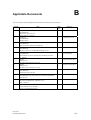
References
B
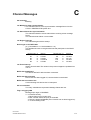
Channel Messages
C
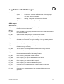
Log Entries of TM Manager
D
Create Import Data for PCS 7/TMOS from PROGRAF AS+
E
Safety Notes
This Manual contains information you must observe to ensure your personal safety
and to avoid damage to the equipment. The notes for your personal safety are marked
by a warning triangle. Notes on damage to equipment only are without a warning
triangle. Depending on the degree of the hazard they are represented as follows:
Danger
means that there will be death, serious injuries or significant damage to equipment if
the corresponding precautions are not taken.
Warning
means that there may be death, serious injuries or significant damage to equipment if
the corresponding precautions are not taken.
Caution
with a warning triangle means that slight injuries may occur if the corresponding precautions are not taken.
Caution
without a warning triangle means that damage to equipment may occur if the corresponding precautions are not taken.
Notice
means that unwanted events or states may happen if the corresponding note is not
observed.
Qualified
staff
Commissioning and operation of the unit may only be performed by qualified staff.
Within the safety-related notes, qualified staff stands for persons who are authorized
to put units, systems and circuits into operations, ground them and mark them according to the standards of safety technology.
Intended use
Please observe the following points:
Warning
The unit may only be used for the applications mentioned in the catalogue and in the
technical description, and only in conjunction with third-party units and components
that are recommended by Siemens.
Faultless and safe operation of the product requires proper transport, proper storage,
setup and installation, and careful handling and maintenance.
Brand names
TELEPERM ®, SIMATIC ® and SINEC ® are registered brand names of Siemens AG.
The other names in this document may be brand names whose utilization by third
parties may infringe the rights of the owner.
Copyright © Siemens AG 1997-2008 All rights reserved
Exclusion of liability
Unless expressly permitted, this document may not be handed
over to a third party, be copied, or its content be used or conveyed. Violation results in damages. All rights reserved, in
particularly in the case of patent granting or utility model registration.
Although we have checked the contents of this document for
agreement with the described hardware and software, there
may still be deviations so that we cannot guarantee a complete
agreement. The specifications in this document are checked
on a regular basis and necessary corrections will be contained
in the subsequent versions. We are grateful for any suggestions on improving the document.
Siemens AG
Automation and Drives
Inustrial Automation Systems
76181 Karlsruhe, Germany
© Siemens AG 1997-2008
Subject to change without prior notice.
Siemens Aktiengesellschaft
Order No. C79000-T8076-C740-17
Preface
Purpose of the
description
This description provides you all the information you need for utilizing
PCS 7/TM. These are primarily
• A product overview with a brief description of the functions, the system
requirements, the interfaces and the delivery form
• The installation and application of the TELEPERM M channel DLL
• The acceptance of configuration data from PROGRAF AS into the WinCC
data manager and the entry of TELEPERM M messages in the WinCC signaling system, using the programming tool TM_Manager
• The peculiarities that must be observed when using WinCC
The listed tools help the user to simplify and optimize the TELEPERM-Mspecific configuration in WinCC.
The standard control displays - (NORA)/OCX blocks - as the basis of tradespecific libraries are described in a separate document.
Readers
This description is aimed at people who work in the configuration of I&C
systems.
Requirements
Working knowledge of the general handling of personal computers and the
work with PCS 7/TM is required.
Furthermore, the reader must be familiar with the TELEPERM M process control system, in particular with PROGRAF AS+ and the OS operator communication and visualization systems.
Several Reference Manuals are available for further information (see Applicable Documents in Appendix B).
Standard
The PCS 7/TM software is based on the international standards
DIN EN 61131-3 (IEC 1131-3) for programming languages.
PCS 7/TM
C79000-T8076-C740-17
III
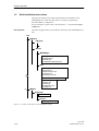
Guide through the
Manual
This Manual is subdivided into the following topics:
• Chapter 1 contains a system overview with general information about
structure, functions, system requirements, interfaces, and delivery form.
•
•
•
•
•
•
•
Chapter 2 describes the TELEPERM M channel DLL.
Chapter 3 describes the programming tool "TM Manager".
Chapter 4 describes the Double Channel Functionality.
Chapter 5 describes the Time Synchonization
Chapter 6 describes the Online Delta Loading
Chapter 7 describes the special features
The Appendix contains a list of the abbreviations used in the document,
and the list of applicable documents.
Conventions
References to other documents are made by means of numbers enclosed by /.../
slash marks. Use this number with the list of applicable documents at the end
of this Manual to find the exact title of the document.
Additional
support
We offer courses that are intended to facilitate your entry into the PCS 7/TM
and/or SIMATIC PCS 7 system. Please contact your local Training Center, or
the Central Training Center in:
1. D-90327 Nürnberg, phone xx49-911 / 895 3202, FAX: xx49-911 / 895 3252.
2. D-78187 Karlsruhe, phone xx49-721 / 595 2917, FAX: xx49-721 / 595 6087.
IV
PCS 7/TM
C79000-T8076-C740-17
Contents
1
2
3
Product Overview...................................................................................................................
1-1
1.1
What Can PCS 7/TM Do ? ......................................................................................
1-2
1.2
PCS 7/TM Product Structure...................................................................................
1-3
1.3
1.3.1
1.3.2
1.3.3
1.3.4
1.3.5
Functions .................................................................................................................
Channel DLL...........................................................................................................
TM Manager............................................................................................................
Format DLL/ Message System................................................................................
Message Generator..................................................................................................
Standard Control Displays OCX (NORA) ..............................................................
1-5
1-6
1-7
1-8
1-9
1-10
1.4
Requirements, Interfaces and Delivery Form..........................................................
1-11
1.5
Brief Installation Instructions..................................................................................
1-12
Channel DLL ..........................................................................................................................
2-1
2.1
Integration in WinCC ..............................................................................................
2-2
2.2
2.2.1
2.2.2
2.2.3
2.2.4
Channel Parameterization........................................................................................
Hardware Requirements ..........................................................................................
System Requirements ..............................................................................................
Authorization...........................................................................................................
Setting up the Connections (Units)..........................................................................
2-3
2-3
2-3
2-3
2-4
2.3
2.3.1
Configuration of TELEPERM M Variables............................................................
Conversion of Variable Names ("Aliasing") ...........................................................
2-11
2-12
2.4
2.4.1
2.4.2
2.4.3
2.4.4
2.4.5
2.4.6
2.4.7
2.4.8
2.4.9
2.4.10
2.4.11
Special Conventions for TELEPERM M ................................................................
Status Displays ........................................................................................................
Defining the Data Types for WinCC.......................................................................
Variable Access by Standard Control Displays OCX (NORA) ..............................
Configuration Guidelines for TML Blocks .............................................................
AKS Blocks.............................................................................................................
BKS Blocks.............................................................................................................
MKS Blocks ............................................................................................................
Field Blocks (GA, GB, FSA, etc)............................................................................
S4 Strings ................................................................................................................
Liefebeat Monitoring...............................................................................................
Status Word Processing...........................................................................................
2-13
2-13
2-13
2-13
2-14
2-14
2-14
2-14
2-14
2-15
2-15
2-15
2.5
Printer Output Diversion .........................................................................................
2-20
TM_Manager..........................................................................................................................
3-1
3.1
3.1.1
Introduction .............................................................................................................
Description of the CSV Configuration Files ...........................................................
3-2
3-3
3.2
3.2.1
3.2.2
3.2.3
3.2.4
ORPA Import ..........................................................................................................
3-5
Description of the Filter File ...................................................................................
3-5
Selecting the ORPA Filter Dialog Box ...................................................................
3-6
The "Select ORPA Parameters" Screen Form ......................................................... 3-12
Special case: Using SRAH block for alarm hiding………………………………… 3-16
PCS 7/TM
C79000-T8076-C740-17
V
Contents
4
5
VI
3.3
3.3.1
3.3.2
Block Import ...........................................................................................................
Description of the Filter Definition .........................................................................
Create Connections .................................................................................................
3-23
3-23
3-26
3.4
Creating Connections ..............................................................................................
3-36
3.5
3.5.1
3.5.2
3.5.3
3.5.4
3.5.5
Message Generator..................................................................................................
General ....................................................................................................................
Communication Channel – Message System ..........................................................
Communication Channel – Message System Configuration ...................................
Entries in Tag Table resp. Component List ...........................................................
Filter for I&C Alarms..............................................................................................
3-36
3-36
3-36
3-37
3-49
3-50
3.6
BATCH Import .......................................................................................................
3-50
Double Channel Functionality ..............................................................................................
4-1
4.1
4.1.1
4.1.2
4.1.3
4.1.4
General ...................................................................................................................
Brief Description .....................................................................................................
Versions ..................................................................................................................
Requirements...........................................................................................................
The Way to the PCS 7/TM-OS DC Project.............................................................
4-2
4-2
4-2
4-2
4-3
4.2
Rate of Tag Transfer ...............................................................................................
4-4
4.3
4.3.1
4.3.2
4.3.3
Naming Conventions...............................................................................................
Name Conflicts Involving OS-relevant Tags and Structure Types .........................
Name Conflicts in the GraCS Folder WinCC (Pictures) .........................................
Name Conflict in the Library Folder WinCC (Scripts) ...........................................
4-5
4-5
4-5
4-5
4.4
4.4.1
4.4.2
4.4.3
Configuring .............................................................................................................
PCS 7/TM Project as Basis .....................................................................................
PCS 7 Project as Basis ............................................................................................
PCS 7 Project and PCS 7/TM Project as Basis .......................................................
4-6
4-6
4-9
4-11
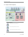
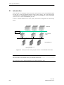
4.5
Example of Plant Configuration..............................................................................
4-12
Time-of-Day Synchronization ...............................................................................................
5.1
Instruction ...............................................................................................................
5-1
5-2
5.2
5.2.1
5.2.2
5.2.3
Time-of-Day Synchronization on the TELEPERM M Plant Bus............................
Primary Time Master ..............................................................................................
Secondary Time Master ..........................................................................................
Time Slave ..............................................................................................................
5-3
5-3
5-3
5-3
5.3
5.3.1
Time-of-Day Synchronization on the Terminal Bus ...............................................
Hint to configuring the time parameter (as of PCS 7/TM-OS, version 3.1)............
5-4
5-5
5.4
Time-of-Day Synchronization with the Double-Channel Server ............................
5-6
5.5
5.5.1
5.5.2
Status-/ and Control Variables, Process Control Messages.....................................
Status-/ and Control Variables ................................................................................
Process Control Messages .......................................................................................
5-7
5-7
5-7
5.6
State Diagram..........................................................................................................
5-8
5.7
5.7.1
5.7.2
5.7.3
Error Situations .......................................................................................................
More than One Primary Time Master on the Bus ...................................................
More than One Secondary Time Master with the same Priority on the Bus ...........
N-UHR on the Bus ..................................................................................................
5-9
5-9
5-9
5-9
PCS 7/TM
C79000-T8076-C740-17
Contents
6
Online Delta Loading.............................................................................................................
6-1
6.1
Online Delta Loading ..............................................................................................
6-2
Special Features......................................................................................................................
7-1
7.1
Special Features of WinCC Versions ......................................................................
7-2
A
Abbreviations .........................................................................................................................
A-1
B
References ...............................................................................................................................
B-1
C
Channel Messages ..................................................................................................................
C-1
D
Log Entries of TM Manager .................................................................................................
D-1
E
Create Import Data for PCS 7/TM-OS from PROGRAF AS+..........................................
E-1
7
Appendices
PCS 7/TM
C79000-T8076-C740-17
VII
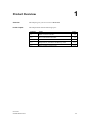
1
Product Overview
Overview
This Chapter gives you an overview of PCS 7/TM.
In this Chapter
This Chapter deals with the following topics:
PCS 7/TM
C79000-T8076-C740-17
Chapter
Topic
Page
1.1
What can PCS 7/TM Do?
1-2
1.2
PCS 7/TM Product Structure
1-3
1.3
Functions
1-5
1.4
Requirements, Interfaces and Delivery Form
1-11
1.5
Brief Installation Instructions
1-12
1-1
Product Overview
1.1
Usage
What can PCS 7/TM Do?
The WinCC operator communication and visualization system can be used for
accessing data from the TELEPERM M automation systems via the
TELEPERM M channel DLL.
Because WinCC is a highly flexible and open system, the system does not support configurations specific to TELEPERM M (of an OS 2xx or an OS 52x, for
example).
Compared with PROGRAF AS+ or OS 525, this situation involves more programming work.
The PCS 7/TM tools are provided to reduce this work and the complexity of
TELEPERM M-specific programming.
WinCC in combination with TELEPERM M can fully replace older OS systems 252 and 265 which are used for operator control and monitoring of
AS 220, AS 23x and AS x88 automation systems.
1-2
PCS 7/TM
C79000-T8076-C740-17
Product Overview
1.2
PCS 7/TM Product Structure
PCS 7/TM
PCS 7/TM
Channel DLL
Option
Basic Process
Control
Option
Advanced Process
Control
TM-Manager
OCX (NORA)
Documentation
ORPA Import
A Block
Manuals
Block Import
B Block
Product Info
Message Generator
C Block
BATCH Import
DZ Block
EG Block
EK Block
EU Block
F Block
FN Block
M Block
MSB Block
R Block
RE Block
RK Block
RN Block
S Block
TVB Block
V Block
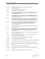
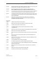
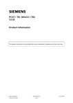
Figure 1-2
PCS 7/TM block diagram
Brief description
The following configuration tools and standard control displays OCX (NORA)
are available:
• Bus-specific channel DLL for handling communication between the automation system and WinCC.
• The programming tool "TM Manager" can be used for generating project
data for the WinCC data manager based on PROGRAF AS+ data and
TELEPERM M messages for the WinCC message system.
• Standard operator system interfaces OCX (NORA) as the basis of tradespecific libraries (layout similar to TELEPERM M and partly to PCS 7,
also symbolic presentation).
PCS 7/TM
C79000-T8076-C740-17
1-3
Product Overview
• Optional Basic Process Control package
-
for configuring and initializing the monitor and image settings;
-
for managing a hierarchy of area names and images;
-
for configuring and initializing the message system.
• Optional Advanced Process Control package
• Image selection via process tag
• Online trending
1-4
PCS 7/TM
C79000-T8076-C740-17
Product Overview
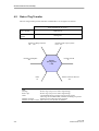
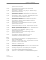
1.3
Functions
Graphics
Message
System
Trends
Data Manager
Variable
Channel DLL
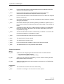
Figure 1-2
Basic structure of WinCC
The tools and standard operator control screens described below are related to
the integration (and configuration) of the TELEPERM-specific variables into
the data manager.
The WinCC online functionality remains unchanged, including its optional
packages.
Notes on configuration change
In WinCC, any change in the database involves the deletion and recreation of
the relevant data. This also applies to derived structures, for example, block instances or messages. Messages associated with the variables must be deleted
before the variable itself is deleted.
The effect of any changes in project data on the AS should first be determined
in WinCC, and after the delta download to the AS you also need to adapt the
OS data.
PCS 7/TM
C79000-T8076-C740-17
1-5
Product Overview
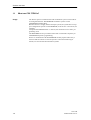
1.3.1
Channel DLL
From the WinCC perspective, the TELEPERM M channel DLL represents a
bus-specific communication driver for accessing data of TELEPERM M (standard) automation systems. Depending on the selection made during Setup, the
user has read/write access to the following data by means of this driver:
•
•
•
•
AS 230, AS 235, AS 388/TM, AS 488/TM
AS 215
AG 150/ 155U
AS 220 S
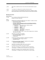
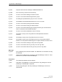
In addition to this selection, it may be required to install an authorization.
WinCC
N-PCI
CP 5613
PROFIBUS
AS 235
AS 230
AS 488
*)
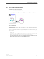
Figure 1-3
Connecting WinCC to TELEPERM M
Notice:
*) Parallel operation of CS 275 and PROFIBUS-TM is not possible.
1-6
PCS 7/TM
C79000-T8076-C740-17
Product Overview
1.3.2
TM Manager
The new WinCC tool was designed to minimize programming work for the
TELEPERM M database, and to assist the user in the import of blocks from
the PROGRAF AS+ engineering system which are required for the database.
PROGRAF AS+ is available in TELEPERM M as an intelligent programming
tool for AS systems and provides an export interface to PROGRAF OS, which
is also used for the communication with WinCC. A data record from an AS
must therefore first be mapped in the PROGRAF AS+ database.
This is the case for the systems AS 230 and AS 235 as well as AS 388/TM and
AS 488/TM.
Because PROGRAF AS+ data are not provided in a single homogeneous data
record, the functions for importing the structures and the blocks instances have
been distributed to several tools.
At the AS side, the full parameter description for all function blocks is maintained in "ORPAs" (original parameter record). These ORPAs form the copy
template when the block instances are generated in the AS.
ORPA import
Because all data configured in the AS is contained in the PROGRAF AS+
export data, a special filter is used to import ORPA data. This filter can be
used to define the parameters for operator control and monitoring.
Block import
Based on the data that has been generated during the import of the ORPA
information, the block instances created in the AS may also be imported to
WinCC.
A data filtering function is also available for the block import.
Create link
This tool creates the connections and the relevant variables.
Note:
Creating the import data by means of PROGRAF AS+ is described in Appendix E.
PCS 7/TM
C79000-T8076-C740-17
1-7
Product Overview
1.3.3
Format DLL/ Message System
Operation of the WinCC message system in combination with the TELEPERM
M channel DLL requires a PMC-S7 format DLL.
The name of this format DLL is "NrmTelpm.nll".
To enable its communication with the channel, a special variable must be configured in the database. This is a "raw data variable" type, named
"TM_MELD_RDV". It can be linked any one of the TELEPERM M channels,
but must be unique.
The TM-Manager creates a pseudo link (i.e. a pseudo AS with bus and device
number 0/0) for the definition of that variable.
The pseudo AS, with name MELD, is created with all necessary variables
when creating a connection.
1-8
PCS 7/TM
C79000-T8076-C740-17
Product Overview
1.3.4
Message Generator
The configuration of messages in WinCC is basically detached from the block
context. This makes it a highly flexible and system-independent function.
However, its use with TELEPERM M involves greater engineering effort and
a high risk of error. A message generator is available for reducing these negative effects and the complexity of message configuration. Its tasks include:
• Creating individual messages with
-
automatically generated message ID
-
message text to be entered by the user
-
associated for S16
-
date/time from the AS
-
alarm class
-
a relevant format DLL (for acknowledgements)
-
block instance name in "Free5" and origin
-
Message texts and service texts can be imported by a CSV file
-
Alarm Hiding masks can be imported by a CSV file
• Entering the message number into the WinCC variable database (defining
default .EventRaw in the variable database).
The block mapper assigns suitable default values to these fields of the standard blocks.
The function indicates delta configurations in the default block messages.
Note:
Restrictions: The message system can not be configured in online mode.
For exception see chapter 6 ("Online Delta Loading").
PCS 7/TM
C79000-T8076-C740-17
1-9
Product Overview
1.3.5
Standard Operator Control Displays OCX (NORA)
OCX shall be used to replace control panels or at least NORA.
TELEPERM M provides by default approx. 20 operator controllable accessible
block types.
Some of these blocks are used in different process-related contexts (the A
block, for example, is used for valves and motors). Earlier versions of OS systems contain separate NORA representations for each of these applications.
Different standard operator control displays will therefore also be required in
the WinCC context.
Using suitable development tools such as VB 5.0 or 6.0, objects of the same
type can be developed for the representation of user function blocks.
Note:
The PCS 7/TM-OCX (NORA) that have been implemented for WinCC are
described in the Technical Description, Order No. C79000-T8076-C741 /41/.
1-10
PCS 7/TM
C79000-T8076-C740-17
Product Overview
1.4
Requirements, Interfaces and Delivery Form
Requirements
A PG/PC with the following system environment is required for using the tools
described earlier:
• WinCC Version 5.0 or later (with the Basic Process Control and
Advanced Process Control options, if used as OS), including PCS 7/TMCS 275 or PCS 7/TM-PROFIBUS.
• PROGRAF AS+, Version 3 or later.
• A DOS- or Windows-based text editor for editing the filter files.
Interfaces
The interfaces are determined by WinCC and the TELEPERM M channel
DLL.
Delivery form
The TELEPERM M channel DLL and the configuration tool TM Manager are
components of the PCS 7/TM-CS 275 or PCS 7/TM-PROFIBUS software.
They are supplied on a separate CD for installation on the destination computer.
A separate authorization must be installed for these products.
PCS 7/TM
C79000-T8076-C740-17
1-11
Product Overview
1.5
Brief Installation Instructions
The practical example in this chapter demonstrates the installation of the
TELEPERM tools. After this setup, the PC is ready for programming.
Recommended PC configuration:
For this information, please refer to the information <..>\Siemens\PCS7\pcs7readme.wri.
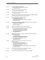
File structure
The following figure shows you the WinCC hierarchy of the TELEPERM tool
files:
LW
\Siemens
\TM_OCX
\WinCC
\BSTMapper
AS23_orpa.999
BausteinFilter.txt
ORPAFilter.txt
TELEPERM M WNF.Support.h
\BIN
BATCHImport.exe
BSTImport.exe
CreateConnection.exe
OrpaImport.exe
TM_Manager_deu.dll
TELEPERM M WNF Support.dll
Telpmdeu.lng
Telpmenu.lng
Telpmfra.lng
TELEPERM M.chn
NrmTelpm.nll
C
\WINNT
\System32
Msvbm60.dll
\drivers
NAT32.sys / NPCI.sys
Figure 1-4
1-12
WinCC file structure for TELEPERM M programs
PCS 7/TM
C79000-T8076-C740-17
Product Overview
Installation of
the channel DLL
The channel DLL files and all necessary software components (driver NAT/N-PCI and communication service TM_Server) are installed via own installation programs.
Installation of TM
Manager
The TM Manager files are installed according to the file structure specified
above.
Installation of
standard operator
control displays
The installation of PCS 7/TM-OCX(NORA) is described in the Technical
Description, Order No. C79000-T8076-C741 /41/.
PCS 7/TM
C79000-T8076-C740-17
1-13
2
Channel DLL
Overview
This Chapter describes installation and utilization of the TELEPERM M channel DLL.
In this Chapter
This Chapter deals with the following topics:
PCS 7/TM
C79000-T8076-C740-17
Chapter
Topic
Page
2.1
Integration in WinCC
2-2
2.2
Channel Parameterization
2-3
2.3
Configuration of TELEPERM M Variables
2-11
2.4
Special Conventions for TELEPERM M
2-13
2.5
Deviation of Printer Output
2-20
2-1
Channel DLL
2.1
Integration in WinCC
Communication drivers for WinCC represent an integral component of WinCC
and must fulfill system standards. This user guide therefore does not cover
general system aspects, but brings the special features of a TELEPERM M
process control system to the user's attention.
WinCC system conventions require the communication driver (also referred to
as "channel" in this manual) to be available at all times during programming
and for the RT mode of WinCC.
Four steps are necessary for installing the channel:
a) Installation of a driver N-AT/N-PCI
b) Installation of the communication service TM_Server (TMSS)
c) Authorization for the channel
d) Integration of the channel into the current WinCC project by download to
the variable database.
This procedure is described in Chapter 5.3 of the User’s Manual "Control Center + Global Scripts + Useradministrator", Volume 1, C79000
- G8200 - C036 /301/.
While the channel is loaded, it is shown as "TELEPERM M.CHN" in the
list of the available communication drivers.
2-2
PCS 7/TM
C79000-T8076-C740-17
Channel DLL
2.2
2.2.1
Channel Parameterization
Hardware Requirements
The WinCC channel concept in theory allows each communication channel to
be operated simultaneously on any number of communication paths which are
based on the same communication mechanisms. These various paths are, for
the most part, represented by separate hardware connections or bus systems,
and are referred to in the channel context as "Links" ("Units").
Two "Links" have currently been implemented for the TELEPERM M channel DLL, i.e. the connection via the PROFIBUS-TM plant bus and the local
bus CS 275.
Notice:
Parallel operation of CS 275 and PROFIBUS-TM is not possible.
A CP 5613 communication processor must be installed and assigned the relevant bus parameters on the PC operating the WinCC system in order to allow a
connection via PROFIBUS-TM, and requires to be loaded with the firmware
after startup of the operating system. A local bus interface N-AT or N-PCI and
a compatible driver software (see Chapter 2.2.3) must be installed to run the
CS 275 local bus under Windows 2000 / 2003 / XP.
2.2.2 System Requirements
Time
Synchronization
2.2.3
Time synchronization on the bus system is an imperative measure for ensuring the correct display of the date/time-of-day in AS messages. All incoming
AS messages will otherwise show the current time of the transmitting AS, but
the incorrect date 01.01.1972. For more information, refer to Chapter 5.
Authorization
The channel for the connection to the TELEPERM M process control system
is a part of the standard WinCC system, and can be installed from there. Its operation requires a separate authorization on the hard disk of the computer that
contains the WinCC base system. This authorization and the relevant setup
program are included in the scope of delivery. To install the authorization,
please run the Automation License Manager.
The further procedure is menu-controlled and self-explanatory. It is here of
importance that you select the destination hard disk that contains WinCC and
the channel DLL.
Note
Please read the notes in "readme.txt" on the floppy disk before you install the
authorization, and pay particular attention to the section explaining the restrictions in handling your hard disk after the authorization has been installed.
PCS 7/TM
C79000-T8076-C740-17
2-3
Channel DLL
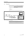
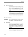
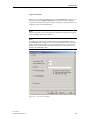
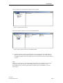
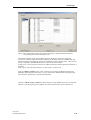
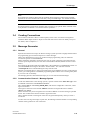
2.2.4
Setting up the Connections (Units)
The channel for linking the TELEPERM M systems supports two bus architectures:
• PROFIBUS-TM via CP 5613 with FDL protocol (L2)
• CS 275 via local bus interface N-AT or N-PCI
After the channel has been loaded into a current project, it appears as follows
in the "Tag Management" branch:
Figure 2-1
2-4
View of the channel in WinCC
PCS 7/TM
C79000-T8076-C740-17
Channel DLL
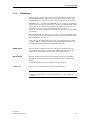
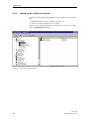
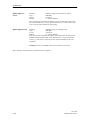
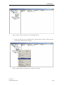
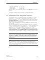
CS 275 address
(L2 unit)
To enable the channel's functions on the PROFIBUS-TM system bus, its local
CS address must be set in the corresponding link (unit). This address applies
only to the L2 unit, because it is selected in the CS 275 context by setting
switches on the N-AT bus interface.
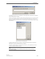
The bus type "L2" and the CS address are set in the TMSS.ini file; see description TM_Server_en.pdf, chapter 2
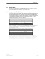
Click the unit of the TELEPERM M communication driver in the tag management dialog. Right-click, and select "System parameters" and a dialog
box appears. Bus and device addresses are always 0.
Figure 2-2
Dialog box System parameters L2
Save Y data
This check box is irrelevant.
Servername
Server name
The name "localhost" in this box may not be modified.
PCS 7/TM
C79000-T8076-C740-17
2-5
Channel DLL
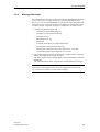
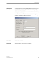
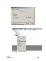
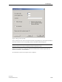
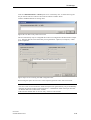
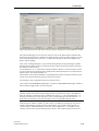
N_AT (CS 275 unit)
port address
The N-AT/N-PCI driver must be installed to be able to operate the CS 275 unit
under Windows 2000 / 2003 / XP (see Chapter 1.5). For a direct CS 275 connection to the N-AT interface, the N-AT port address (not for N-PCI !) must be
selected and the corresponding software configured in the same window. After
you have entered a valid address, reset and restarted the computer, and then
press "Init" in this window. After successful initialization, the DIP switch settings on the N-AT or N-PCI interface appear in the "Bus Address" and "Node
Address" fields.
Figure 2-3
Dialog box for the selection of the port address (CS 275)
Saving Y data
This option is irrelevant.
Servername
The name "localhost" in this box may not be changed.
2-6
PCS 7/TM
C79000-T8076-C740-17
Channel DLL
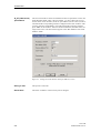
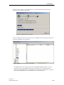
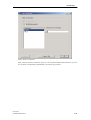
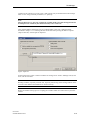
Logical connections
Before you can configure the data of a real AS TELEPERM M in WinCC, you
must first create the "logical connections" in the channel. This connection
represents an automation system on the bus. In WinCC, a logical connection is
created by means of the TM Manager.
Note:
All the configuration steps described below should be performed by means of
the TM Manager described in Chapter 3.
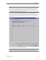
Note:
It is imperative to fill out the "CS 275" tab for the TELEPERM M, CS 275
and PROFIBUS-TM configuration, because this determines the bus and node
address of the AS whose data are to be configured in WinCC. These settings
also have to be made for AS 388/TM and AS 488/TM systems directly connected to the PROFIBUS-TM!
Figure 2-4
PCS 7/TM
C79000-T8076-C740-17
CS 275 tab – Parameters
2-7
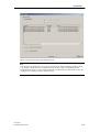
Channel DLL
Status frames
For each unit (i.e. for each AS) you can specify whether status message frames
shall be received from the corresponding AS or not.
Plaintext system
messages
For each unit (i.e. for each AS) you can specify whether system messages shall
be received from the corresponding AS or not.
Plaintext operator
communication
messages
For each unit (i.e. for each AS) you can specify whether or not operator control
messages shall be received from the corresponding AS.
Operator control messages are stored in the "operator control messages" class.
Plaintext MEL
messages
For each unit (i.e. for each AS) you can specify whether or not messages from
the MEL blocks shall be received from the corresponding AS. MEL messages
are stored in the "TELEPERM M/MEL messages" class.
Accessing an AS
Each connection, i.e. the link to an AS, can be established or shut down selectively.
For information on opening and ending connections by means of variable
control, please refer to the next Section "Link-specific internal variables of the
TELEPERM M channel", paragraph "@...@ForceConnectionState".
The procedures described in the "Logical connections" section must be
performed for each new connection.
Internal connectionspecific variables of
the TELEPERM M
channel
The connections are controlled by connection-specific internal variables,
which are created by means of a wizard. Their name is formed by the name
of the corresponding connection and an identifier. A "@" prefix identifies the
connection name as system variable.
Example: "@connectionname@identifier".
All internal connection-specific internal variables are combined in the variable group "@connectionname".
These variables are created by means of the TM Manager (see chapter 3).
@...@ConnectionState Meaning:
Type:
Access:
Default:
Connection status
DWORD
Read
0 = "Error"
This variable can be used to determine the current connection status:
0 = Error
1 = Connection is ready
2-8
PCS 7/TM
C79000-T8076-C740-17
Channel DLL
@...@ConnectionError Meaning:
Type:
Access:
Default value:
Cause of error
DWORD
Read
0 = "No error"
The variable identifies the error that has caused the connection shutdown.
Default value = 0, i.e. the connection has not been established yet, or there is
no error. The variable is loaded with 0 (no error) when the connection is reestablished. The channel stores the error code here.
0
= No error
<> 0 = Error code
@...@ConnectionError
String
Meaning:
Type:
Access:
Default value:
Error cause as string
TEXT8 [128]
Read
"" = "No error"
The variable contains an error string that describes the cause of the connection shutdown. The string is output in the currently selected language. Default
value = ""; i.e. the connection has not been established yet and/or there is no
error.
""
"Error hhhh"
@...@ConnectionError Meaning:
Count
Type:
Access:
Default value:
= No error
= The error hhhh has occurred
(hhhh = hexadecimal error code)
Counter for link errors
DWORD
Read
0 = "No error"
Whenever a connection ends, the value of this variable is incremented by one
count. The counter restarts at 0 after an overflow.
@...@ForceConnection Meaning:
State
Type:
Access:
Default value:
Preferred connection status
DWORD
Write
1 = "Established"
This variable can be used to report the preferred connection status to the
channel. Its value is a logical 1 under "normal circumstances", i.e. the channel is trying to connect. The channel disconnects when this variable is reset to
0.
Writing to this variable has the following effect:
0 = Preferred connection status: Not connected
Æ If connected, then disconnect
1 = Preferred connection status: Connected
Æ If not connected, then connect
@MELD@Connection
BATA
PCS 7/TM
C79000-T8076-C740-17
Local bus / station address in hexadecimal format (e.g. 653 = bus 6, station
83).
2-9
Channel DLL
@MELD@Cache
S16AT
Meaning
Type:
Access:
Default:
Read S16 string (AT) once during startup
DWORD
read/write
0 = read on demand
This variable tells the channel to read the process-related names (S16) from
the AS on demand ("0") or out of the internal cache ("1"); this cache is read
once at start up and actualized by OS writings.
@MELD@CacheS32
Meaning
Read S32 string once during startup
Type:
DWORD
Access:
read/ write
Default:
0 = read on demand
This variable tells the channel to read the S32 strings of the interface blocks
of SIMATIC BATCH from the AS on demand ("0") or out of the internal
cache ("1"); this cache is read once at start up and actualized by OS write
operations.
Warning: In case of redundant servers this cache may not be used!
More variables concerning Time Synchronization see chapter 5.
2-10
PCS 7/TM
C79000-T8076-C740-17
Channel DLL
2.3
Configuration of TELEPERM M Variables
Variables of a TELEPERM M AS must be created on block instance level in
the WinCC variable database by means of TM_Manager. To save as much time
as possible in the variable configuration dialog, it is imperative to adhere to the
following naming conventions for variables to be updated by means of the
TELEPERM M channel DLL.
a) The variable name must always consist of these elements:
• Prefix
(PR)
• Block type name
(BT)
• Block instance name
(BNR)
• Access type internal / external
(ZT)
• Parameter type
(PT)
• Parameter number
(PNR)
b) These elements must be specified in a fixed sequence in the following format:
PR_BT_BNR.ZT_PT_PNR
The elements of structured variables used by means of the structure editor are:
• BT
• BNR
• ZT_PT_PNR
=
Name of the structure
=
Instance of the structured variable
=
Name of the structure member
The prefix is optional and is only required for creating unambiguous variable
names in the WinCC database. It does not need to be defined at the time the
structure is created, and may be user-specific, because the channel does not
evaluate this element of the variable name. However, the user must ensure that
each variable name begins with a letter and is unique throughout the WinCC
database.
The separators "_" between PR, BT and BNR and "." between BNR and ZT
are mandatory.
Likewise, a user-specific name may be assigned to the structure, but should
generally reflect the block that is mapped by the structure.
Example of naming a TELEPERM M variable:
If the actual value of the RN block 34 in the AS with BATA 1/25 shall be
accessed, the corresponding WinCC variable may be called, for example,
AS125_RN_34.EXT_EA_18.
Any variable that does not comply with these conventions is rejected by
the channel during the RT startup, and is not updated.
PCS 7/TM
C79000-T8076-C740-17
2-11
Channel DLL
2.3.1
Conversion of Variable Names ("Aliasing")
To connect PCS 7/TM to SIMATIC BATCH (from V6.0) the block and variable names must be converted to meet PCS 7 conventions ("Aliasing"). This
means that quasi-physical parameter names such as EXT_EA_1 must be replaced with a technological parameter name according to PCS 7 conventions,
for example BA_EN. The conversion of technological to quasi-physical names
required for operation with TELEPERM M-AS takes place within the channel.
In PCS 7/TM version 3.0 and later, the "Parameter" column in the WinCC
variable database contains three consecutive entries:
1. Parameter short name within the AS block
2. Quasi-physical parameter name (TELEPERM M)
3. Technological parameter name (PCS 7)
The first and third entries are identical in TELEPERM M function blocks
which contain the quasi-physical parameter name.
An exception are here the field blocks, i.e. FA, FB, FSA, GA, GB, GM and
GT. These have a @ prefix, followed by the block type and a consecutive
number. The third entry corresponds with the second.
Note
This conversion is allowed only for function blocks operating with SIMATIC
BATCH from V6.0.
2-12
PCS 7/TM
C79000-T8076-C740-17
Channel DLL
2.4
Special Conventions for TELEPERM M
To be able to process the data of a TELEPERM M process control system in
WinCC, the following marginal conditions must be adhered to when configuring operator control and monitoring (OCM) data:
2.4.1
Status Displays
The status displays in WinCC do not offer the degree of flexibility and performance as those of TELEPERM M. Generally, the AS data for these image
objects must first be converted into WinCC-compliant internal variables by
means of user-specific C scripts, and are then logically linked with the status
displays in the images.
2.4.2
Defining the Data Types for WinCC
You must always define the data type of the variables you configure for your
WinCC database. The channel DLL then converts the AS values into the default WinCC format.
Notice:
Creating the variables in WinCC in a format that is expedient for the data in
the TELEPERM M AS lies within the user's responsibility.
The TELEPERM M data types and their formats can be found in the manual
"System software AS235", C79000-G8076-C416 /1/.
2.4.3
Access to Variables by Means of Standard Control Displays OCX
(NORA)
In the WinCC context, the standard control displays represent the counterpart
of the TELEPERM M control panels. The structured instance assigned to the
standard operator control display represents the data interface between the
standard control displays and the WinCC data base. Naming conventions must
be adhered to when configuring TELEPERM M PCS data, i.e. the member
name of the structured variable must represent a text-based description of the
parameter address in the AS. This method minimizes efforts required for programming data records in WinCC. If a standard control display is used for accessing a specific block type that exists in different AS types, the text-based
address of the relevant parameters must be identical for these systems.
Note:
Structures cannot be modified later if the database already contains instance
files for these types!
PCS 7/TM
C79000-T8076-C740-17
2-13
Channel DLL
2.4.4
Configuration Guidelines for TML Blocks
The configuration rules laid down in the corresponding TELEPERM M manuals always apply to the configuration of TELEPERM M variables. We explicitly want to point out here that parameters from TML blocks must always be
assigned the "INT" access type. Where TML blocks are concerned, technical
reasons cause external parameters to be discarded by the channel and not to be
updated during startup. All other blocks from the standard functionality spectrum may be assigned external or internal parameter IDs (even if these are not
operator-controllable function blocks).
2.4.5
AKS Blocks
In contrast to all the other blocks, parameters can not be read from the AKS
block. The channel processes only the (maximum 28) analog values of the
block's message frame. In the structure, these values must be structured as the
parameters 1 EA through 28 EA. If other parameters are created, they return
random values to the data manager.
2.4.6
BKS Blocks
In contrast to all the other blocks, parameters can not be read from the BKS
block. The channel processes only the (maximum 128) binary values of the
block's message frame. In the structure, these must be structured as the parameters 1 EB through 128 EB, or 1 ID through 8ID for word access. If other
parameters are created, they return random values to the data manager.
2.4.7
MKS Blocks
Because MKS bits are merely intended for creating messages, this block type
is an exceptional feature in WinCC processing. In contrast to the BKS block,
the individual MKS bits are not configured, and only the WinCC block status
with the .EventState, .EventTrans# and .EventRaw# member variables is processed. For details on the function of these variables, refer to the description of
the status word evaluation in Chapter 2.4.11.
2.4.8
Field Blocks (GA, GB, FSA, etc)
All fields are generated with the maximum of length by the TM Manager. The
channel gets the real length of the block instance.
Possible lengths are from 1 through 256.
2-14
PCS 7/TM
C79000-T8076-C740-17
Channel DLL
2.4.9
S4 Strings
The "S" type parameters partially used in AS 23x systems are handled like S4
strings, i.e. only four characters are processed. From parameters of that type in
TML blocks only the first character can be read.
2.4.10
Lifebeat Monitoring
This function is a standard component of a channel DLL. When a logical link
is applied, the channel automatically monitors the relevant system in each scan
cycle by means of the TELEPERM M lifebeat message frames, irrespective of
whether variables have been configured in this connection or not. From the
WinCC perspective, the result of this function is reflected in the status of the
logical connection. It is therefore possible to monitor all systems at
TELEPERM M by means of the channel DLL when you apply a corresponding logical link. The graphic view of the system configuration can be created
in WinCC by means of the "Lifebeat Monitoring" editor. Third-party systems
(with KSN-AT, for example) are not monitored.
2.4.11
Status Word Processing
TELEPERM M status words can not be processed directly for the output of
alarms in images and in the message system. They are mapped in the channel
to the .EventState variable members which are known both in WinCC and
SIMATIC S7. For information on the configuration of essential alarm data and
structures, refer to the S7-300/400 System Software Reference Manual /300/.
The following configuration rules apply to TELEPERM M standard blocks:
WinCC block status and TELEPERM M status word
Message and alarm processing in WinCC and the corresponding process control engineering software packages is based on the S7 PMC concept that has
been developed for the OCM system. Users of the WinCC software and its corresponding optional packages must conform with the following rules when
configuring an OCM system.
The structure of each block that has an alarm response assigned in WinCC
must satisfy stringent conventions. Besides the parameters that are configured
by the user for the OCM functions, certain message processing parameters
must be applied. These are in detail:
•
•
•
•
•
•
•
•
•
.EventState (LONG)
.EventRaw#1 (LONG)
.EventRaw#2 (LONG)
.EventRaw#3 (LONG; MKS only)
.EventRaw#4 (LONG; MKS only)
.EventTrans#1 (LONG)
.EventTrans#2 (LONG)
.EventTrans#3 (LONG; MKS only)
.EventTrans#4 (LONG; MKS only)
The notation shown above is obligatory, because the TELEPERM M channel
identifies the variables by means of their member name!
PCS 7/TM
C79000-T8076-C740-17
2-15
Channel DLL
Functions of the member variables in particular:
1.
.EventState –
Standardized
block status /
WinCC status
To provide a uniform view of the alarm status of configured blocks in all applications, the type-dependent alarms of the blocks are assigned default alarm
bits in this standardized block status. The double word bits 31 to 16 indicate
the standardized alarm status, and bits 15 to 0 the associated acknowledgement
status. For details on the various bits, refer to the "System Software for S7300/400" Reference Manual /300/. Original alarm information is routed to the
standardized status based on the data entered in the .EventTrans# member
variables. The TELEPERM M process control system either derives the alarm
information from the individual block states, or it is transferred by means of
MCS. Standard blocks have a fixed relationship between the TELEPERM M
status word and the standardized block status in WinCC. This relationship is
represented in the routing information of the .EventTrans# member variable
(see there).
2.
.EventTrans# routing information
for standardized
block status
The message concept of WinCC and PCS 7 allows the assignment of any alarm
class to an alarm bit. This is done by routing the alarm bit to the location of the
standardized block status that belongs to the alarm class. This routing rule is
specific to the block and the application, and must be configured as default by
means of the corresponding properties dialog in WinCC. WinCC assumes that
any alarm information received from an AS does not contain more than 8
alarm bits. Complete mapping of the alarm bits in the standardized block status
requires a double word for each one of these alarm bytes. Because every status
word in TELEPERM M consists of 10 status bits plus an additional acknowledgement bit, you must configure two member variables for each operatorcontrollable block, plus four for the MKS member variables. The sequence of
the member variables corresponds to a right alignment of the alarm bits in the
TELEPERM M status word (i.e. .EventRaw#1 = routing information for bits 0
- 7 of the TELEPERM M status word, .EventRaw#2 for bits 8 - 9).
The channel DLL handles the acknowledgement bit separately. The table on
the next page shows which default start values must be entered in the variable
database for the various block types of the standard TELEPERM M spectrum.
3.
.EventRaw# - raw
data from
TELEPERM M
status word
In the WinCC context, this member variable fulfils two functions. During system startup, this variable reports the valid alarm message numbers to the channel for the alarms. Based on this message number, the WinCC message package determines which message texts are to be output in RT mode. For information on how to generate a message number that is unambiguous throughout the
system, refer to the System Software for S7-300/400 Reference Manual /300/.
After the message number has been accepted, the TELEPERM M channel
stores the original status word from TELEPERM M in these variables in a leftaligned format. Like in the .EventTrans# members, the first member contains
the alarm bits 0 - 7, the second member the remaining bits.
2-16
PCS 7/TM
C79000-T8076-C740-17
Channel DLL
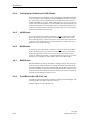
Table 2-1
Description of the routing information for TELEPERM M standard
blocks
Block
. EventTrans#1
. EventTrans#2
A
0
9
B
0
9
C
0
0
DZ
-1.728.053.248
9
EG
-1.728.053.248
9
EK
-1.879.048.192
9
EM
39.168
9
EU
36.864
9
EV
-1.728.053.248
9
F
16.777.200
0
WAF = Error (tolerance)
11.250.603
9
WAF = Warning
13.487.565
9
WAF = Alarm
15.724.527
9
G
-1.728.053.248
0
GK
-1.728.053.248
0
M
12.246.270
9
MSB
-1.879.048.192
9
R
12.246.270
9
RE
36.864
0
WAF = Error (tolerance)
12.226.560
9
WAF = Warning
14.454.784
9
FN
RK
PCS 7/TM
C79000-T8076-C740-17
2-17
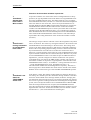
Channel DLL
Table 2-1
Continuation
Block
WAF = Alarm
2-18
. EventTrans#1
. EventTrans#2
16.683.008
9
RN
12.246.270
9
RSKB
12.311.806
9
S
1.073.741.824
9
T
47.802
0
TVB
9.437.184
9
V
0
9
TML
19.423
9
PCS 7/TM
C79000-T8076-C740-17
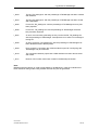
Channel DLL
Message information from AS via MKS frame
31
24 23
16 15
8
TELEPERM M representation
7
7
Alarm (AH)
Warning (WL)
7
0
1
0 1 1 0 1 0 1
7
0
1
0 1 1 0 1 0 1
MKS
.EventRaw#1
0
.EventRaw#2
0
.EventRaw#3
7
0
.EventRaw#4
7
Routing information
7
0
0
.EventTrans#1
F 0 F F 0 C 0 C
.EventTrans#2
7
0
.EventTrans#3
7
0
WinCC
representation
A
la
r
A m(
la A
rm H
)
W
ar ( A L
W nin )
ar g
(
To nin WH
le g ( )
To ran WL
le ce )
ra (T
nc H
e )
(T
L)
.EventTrans#4
.EventState
Message state 1 0 0 1 0 0
31
24 23
16
15
0
1. The AS sends messages to the OS in the MKS frame.
2. In WinCC, the information is stored in .EventRaw#.
3. The routing information provides the assignment to the WinCC representation:
- All alarms (bit 7, 5, 4 in MKS frame) must land in bit 31 in .EventState.
This is why the routing information F hexa (16th bit in the .EventState high word) is in the related .EventTrans# for
alarms.
- All warnings (bit 2, 0 in MKS frame) must land in bit 28 in .EventState.
This is why the routing information C hexa (13th bit in the .EventState high word) is in the related .EventState for
warnings.
4. If all other digits of the example are unused (0), the following value results as the default value of .EventTrans#1
(must be entered manually:
F0FF0C0C hexa; a negative decimal number due to the leading 1
Complement :
+1
:
decimal
:
negated
:
Figure 2-9
0F00F3F3 hexa
0F00F3F4 hexa
251720692 dec.
- 251720692 dec. value that is to be entered
Example for routing information .EventTrans# with messages in the MKS
PCS 7/TM
C79000-T8076-C740-17
2-19
Channel DLL
2.5
Printer Output Diversion
The printer output of the OS 252 and OS 26x operator control and monitoring
systems can be diverted to PCS 7/TM. This requires the following measures:
- In WinCC: Establish a "connection" in the corresponding channel to this
OS, and set the "Plain text: operator control messages" checkbox. Do not
define any further variables below.
- In OS 252 or OS 26x: Enable printer deviation.
2-20
PCS 7/TM
C79000-T8076-C740-17
3
TM Manager
Overview
This chapter provides you with information about the creation of the variable
database and the configuration of messages by means of the TM Manager.
This Chapter
This chapter deals with the following topics:
PCS 7/TM
C79000-T8000-C740-17
Chapter
Topic
Page
3.1
Introduction
3-2
3.1.1
Description of the CSV Configuration Files
3-3
3.2
ORPA Import
3-5
3.3
Block Import
3-23
3.4
Creating Connections
3-36
3.5
Message Generator
3-36
3.5.5
Filter for I&C Alarms
3-50
3.6
BATCH Import
3-50
3-1
TM Manager
3.1
Introduction
A defined variable database in the currently relevant project is prerequisite for structured
programming in WinCC.
All the process parameters to be used in any application are declared in this variable database, in
the context of WinCC and of the connected TELEPERM M automation systems. Same as with
TELEPERM M automation systems, the initial step is here to form the basic structures for each
block type, and to use copies of these as templates for the creation of block instances. The data
of a block structure must contain all the parameter definitions required for the corresponding
block type. The user may create any number of basic structures for a block type, each with
different program code.
In PCS 7/TM-OS V3.0 and later, the WinCC variable database and messages are configured by
means of the tool TM Manager.
TM Manager contains the following components
•
ORPA Import
•
Block Import
•
Create Connection
•
Message Generator
•
BATCH Import
Input data for TM Manager are based on the following AS export data of the PROGRAF AS+
Engineering System:
•
AS-independent ORPA data for the standard function blocks (A23_orpa.999)
•
AS-specific ORPA data for user function blocks (AS_orp.xyy)
•
AS-specific library files (Belxyy.dat)
(x = bus address, yy = device address)
•
Including the filter files for ORPA data and function blocks
Please look at Appendix E: Create Import Data for PCS 7/TM-OS from PROGRAF AS+
Note:
In a project only one ORPA filter and only one block filter for each connection (AS) is
allowed. Delta parts must be added to existing filter files. Separate delta runnings, i.e. with
subsets of ORPA or block filters, are not allowed.
Generally a project contains several connections (AS). Once such a connection has been
configured including variables, it should not be deactivated during the block import of a
following TM manager session if the variables have to remain in the Tag Management as
well as in the result data (*.map) of TM manager.
The TM Manager components save their settings and results data to the teleperm folder of the
WinCC project (TM_settings.txt und *.map).
PCS 7/TM
C79000-T8000-C740-17
3-2
TM Manager
Note:
The program paths of the source computer set in the TM_settings.txt file are retained when you
copy a project to another PC. This also applies when WinCC or SIMATIC tools are used. These
must be adapted for further processing on the destination computer.
A changed project name (e.g. WinCC project duplicator) must also be adapted.
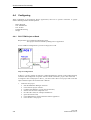
You can currently start TM Manager by running the program ORPAImport.exe from the
subdirectory <...>\Siemens\WinCC\bin, or by selecting the Start Æ Programs Æ
TM_Manager Æ ORPAImport command. You can also run the various TM Manager
components separately by means of their own executable files. After completion of a component
the following component will be initiated automatically. Exception: Message Generator and
BATCH Import do not have successor components.
Note:
We advise the use of the filter files for importing ORPA data and blocks when selecting ORPA
types and block instances, and also to refrain from manipulation over and above that, except in
special situations.
Manual operations with WinCC Explorer can cause inconsistencies of the Tag Management and
the configuration of the Alarm Logging.
3.1.1
Description of the CSV Configuration Files
Configuring service texts during block import and additional variables and message texts during
message generator through the manual method may also be done via a CSV configuration file in
CSV format.
This configuration file has the following construction:
Die CSV configuration file starts with a heading line that’s contains the description of the
columns or an empty line. The following lines look as follows:
AS description Bit number
Block type,
block name
Å max 80
characters Æ
Additional
variable
(Free4)
Å max 50
characters Æ
Message text
Å max 63
characters Æ
Service text
AS description:
Bit number:
Additional variable:
Message text:
Service text:
Block type/name as defined in WinCC Tag Management
Bit number in status word
Freely configurable variable for message block „Free4“
Freely configurable static text for message block „Event“
Freely configurable static text for internal variable <block
instance>.SERVICETEXT
As separating character only semicolon (;) has to be used.
PCS 7/TM
C79000-T8000-C740-17
3-3
TM Manager
Importing the service texts during block import only the columns
AS description
Bit number (must be empty)
Service text
are evaluated.
Importing the additional variables and message texts during message generator only the columns
AS description
Bit number (0 … 31)
Additional variable
Message text
are evaluated.
For each block instance the file may contain several entries as may be seen in the following
example
Example of a CSV configuration file (extract):
VARIABLE; BITNUMBER; ADDIT. VARIABLE; MESSAGE TEXT; SERVICE TEXT;
AS01_M_10;;;Service text for M10;
AS01_M_10;0;AS01_M_10.EXT_EA_11; Temperature too deep @7%g@;;
AS01_M_10;1;AS01_M_10.EXT_EA_12; Temperature too high @7%g@;;
AS01_M_10;2;AS01_M_10.SERVICETEXT; Temperature deep @7%s@;;
AS01_M_10;3;AS01_M_10.SERVICETEXT; Temperature high @7%s@;;
AS01_M_10;4;AS01_M_10.SERVICETEXT; Temperature rising @7%s@;;
AS01_M_10;5;AS01_M_10.SERVICETEXT; Temperature falling @7%s@;;
AS01_M_10;8;AS01_M_10.SERVICETEXT; @7%s@;;
Explanation:
The first line contains the heading line which describes the columns. The second line describes
the content of the service text which will be allocated to the block instance during block import
(see also chapter 3.3 Block Import).
Line 3 to 9 describe the additional variable which has to be read after the message had raised as
well as the message text which may be supplemented by this additional variable (see chapter 3.5
of Message Generator).
CSV configuration files with message classes/types/priorities and Alarm Hiding masks
Configuring message parameters and/or Alarm Hiding masks during Message Generator is done
via a CSV configuration file in CSV format.
This CSV file is generated with an EXCEL macro. Therefore it is not necessary to give a
description of its structure. Details are described in chap. 3.5.3.
PCS 7/TM
C79000-T8000-C740-17
3-4
TM Manager
3.2
ORPA Import
The ORPA Import program is used to import all the required function block structures, i.e. the
ORPA data, to the WinCC variable database.
The ORPA Import function processes the ORPA filter and allows, over and above that, the
implementation of additional function blocks and further function block parameters.
Note:
The function blocks EM1B, IEOP, IEPH, TR1B and UNIB are reserved for SIMATIC BATCH
applications and may never be implemented in the WinCC variable database from other
applications.
Block structures of the type IEOP, IEOP_*, IEPAR_*, IEPH, IEPH_* and TAG_COLL are
reserved exclusively for SIMATIC BATCH applications.
3.2.1
Description of the Filter File
Each ORPA data record consists of the block type name in the AS (e.g. "RN") and of the
description of the various parameters of this block. The filter definitions for the ASCII file used
for an ORPA import must be specified accordingly. Up to four lines can be defined in the filter
file for each imported block type:
•
Block type name
Consists of a maximum of four characters and must be terminated with ":".
•
Description of parameters to be applied
These entries are arranged based on the order of the I/Os and have the following syntax:
"Type" = {parameter number}
The notation of the "Type" is E for the inputs and A for the outputs of standard function
blocks, and for the user blocks "type" you always select I. The parameter numbers can
be separated by comma, or defined as a range by means of the "-" character. Each filter
file line may contain up to 255 characters. A separate line is created for each parameter
type.
Example:
RN:
A = 1, 3
E = 1-9, 11, 13-16, 96
S = STATUS
This filter definition has the effect that, based on the ORPA file, a RN block structure is created
that contains the outputs 1 and 3 and the inputs 1 to 9, 11, 13 to 16 and 96.
The string parameters of a blocks must be declared as "input" parameter type.
PCS 7/TM
C79000-T8000-C740-17
3-5
TM Manager
•
Status information
A further entry covering the standard blocks with status word and the TML blocks is
required in the filter file. Its identifier is "S = STATUS", and it is entered below the
type name same as the other definitions.
Because the system always imports the internal parameters for the TML blocks, it is
here not necessary to differentiate between inputs and outputs. In the filter file, all
parameters required are therefore defined as internal inputs.
Entries in the filter file that are temporarily not required can be disabled with the ";" character if
this character is the first character in a line.
Independent of the filter file text references with the names of <block instance>.#areaname,
<block instance>.#blocktype and <block instance>.#comment are created for each block type.
The default value of <block instance>.#blocktype is the block type name and that of <block
instance>.#comment is the block comment (independent of an instance); they are shown after
instancing the block. Besides, for each block type the internal variable <block instance>
.SERVICETEXT is generated.
3.2.2
Selecting the ORPA Filter Dialog Box
When the ORPA import is initially started in a WinCC project, the "Select PROGRAF import
file" window shows the PROGRAF AS file A23_ORPA.999 by default (all standard function
blocks), the "Select PROGRAF library import file" window is blank, and the "Disable import of
PROGRAF file data" and "Use filter file" are disabled:
PCS 7/TM
C79000-T8000-C740-17
3-6
TM Manager
Figure: Initial run of the ORPA Import
You select the ORPA files to be processed by clicking "....", next to "Select PROGRAF import
file". Hereby: A23_ORPA.999 or AS_ORP.999 contain the ORPA files of the standard function
blocks, and AS_ORP.xyy (xyy = bus/device ID) contains the ORPA files of the user function
blocks (TML). All ORPA data for the project are selected in this step. You can cancel a selection
by clicking ">".
Note:
If the ORPA Import gets files containing different definitions for the same block type only the
last recognized will be used.
PCS 7/TM
C79000-T8000-C740-17
3-7
TM Manager
You select the library file BELxyy.DAT for each AS (= connection in the context of WinCC) to
be configured by clicking "...", next to "Select PROGRAF Library File". It is strongly advised to
rename the BEL.DAT library files used for the various AS systems in the Windows Explorer, in
order to assign an unambiguous file name that shows the bus/device IDs, for example
BEL604.DAT. You can cancel a selection by clicking ">".
An import of ORPA data and of blocks is not possible if these library files do not exist.
A common ORPA filter file can be selected by selecting the "Use filter file" check box. If you
choose not to select this option, all parameters of all the function blocks in the PROGRAFORPA files are imported to the WinCC variable database.
Simply press "next Æ" if you do not wish to make any changes to the ORPA structures, in
contrast to a previous editing run.
PCS 7/TM
C79000-T8000-C740-17
3-8
TM Manager
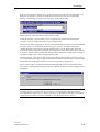
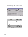
Figure: Initial run with input of file paths
This figure shows the configuration of 4 AS, AS 606 contains user-defined function blocks. The
AS 604, 607 and 609 contain standard function blocks only. One ORPA filter is used.
Click "Next Æ" to fetch the ORPA structures from the configured files and to prepare them in
project-specific files (as_orpa-standard.map or as_orpa_userdef.map). These files are necessary
for further operation with TM Manager and the channel. In the next step, you change to the
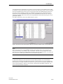
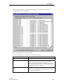
"Select ORPA Parameters " screen form.
PCS 7/TM
C79000-T8000-C740-17
3-9
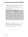
TM Manager
After the initial run, all the block instances have been created in WinCC and the "Disable import
of PROGRAF file data" check box is set, provided no further modifications are required.
Because the configured files are not read in again in this case, the data are fetched from the
project-specific map files instead. If new types should be added (eg. change of an ORPA filter)
the check box has to be reset.
Fig.: ORPA Import after the run
Click "Next Æ" to go to the "Select ORPA Parameters" dialog box.
PCS 7/TM
C79000-T8000-C740-17
3-10
TM Manager
If the SRAH block resp. the WinCC structure STATEREP is used for Alarm Hiding then it must
be pointed out that the structure STATEREP is not generated by the ORPA-Import. It has to be
created in advance in a PCS 7 configuration session. More details are described in chap. 3.2.4.
If ORPA-Import recognizes a SRAH block in a PROGRAF AS import file, and the structure
STATEREP isn’t yet created in WinCC then ORPA-Import displays a corresponding message:
Fig: Message to missing STATEREP structure
PCS 7/TM
C79000-T8000-C740-17
3-11
TM Manager
3.2.3
The "Select ORPA Parameters" Screen Form
All the function blocks in the PROGRAF ORPA files are displayed on the left window of the
"Select ORPA Parameters" dialog box. The two columns contain the function block names as
stored in the AS, and their name in the WinCC variable database. The content of both columns is
identical, with the exception of the SIMATIC BATCH function blocks.
The corresponding check box is selected for blocks included in the ORPA filter. By selecting the
check box with a mouse click, the parameters selected in the ORPA filter are displayed on the
right-hand window in the "Parameter" column. The "Comment" column shows the physical
name of each parameter, while the "WinCC Parameter Name" column shows its name from the
WinCC variable database. The contents of both columns are identical save for the SIMATIC
BATCH function blocks.
An active check box on a gray background indicates that a structure already exists for the
relevant function block in the WinCC variable database.
In addition to the filter definitions, you can select further blocks and add parameters to existing
blocks. If you cancel the selection of a parameter, you receive a corresponding warning box.
When you add a function block, you are prompted to include status information for this block
type. You can only confirm this option if the function block generates a status word in the AS.
On the left window, click "Tag all" to select all parameters, or click "Untag all" to select none.
Figure: Screen form that appears when you click "Next" in the ORPA file selection dialog
PCS 7/TM
C79000-T8000-C740-17
3-12
TM Manager
The right-hand side of the dialog box contains two boxes showing you the default values of the
EventTrans#1 und EventTrans#2 variables for blocks with status word. These values are enabled
and can be modified type-specific for the user function blocks and standard function blocks. If
the values of the EventTrans variables for standard function blocks are changed then there is
abandoned on the TELEPERM arrangements of the TELEPERM M status bits. By clicking a
button the modified values can be reset to the original default values if the block type is not yet
generated in WinCC.
For further information, refer to the "Block Import" section.
Figure: Screen form with shown button „Reset to EventTrans default values“ for the SFB “EG“
Note:
The OCX image blocks in TELEPERM M NORA representation don’t use “EventTrans” but
they access directly to “EventRaw” resp. “EventState”. Therefore if the arrangements of the
status bits were changed the standard delivered OCX cannot be applied anymore. In contrast the
OCX in a PCS 7-similar representation show the modified range state.
Note:
As described already above the check boxes for the ORPA parameters are activated if the
parameters are selected in the ORPA filter file. But a check box doesn’t get a grey background
if the parameter is already created as an element of a type structure in the WinCC database. The
really created elements in a WinCC type structure, which present the ORPA parameters, can
only be read by the WinCC Explorer.
PCS 7/TM
C79000-T8000-C740-17
3-13
TM Manager
Note:
Existing (ORPA) structures can only be deleted by means of the WinCC tools (by removing
them from the variable database/structure types).
On the left window, click "Tag all" to select all the parameters of your selected function block,
or click "Untag all" to select none:
Figure: View of the selected ORPA parameters
PCS 7/TM
C79000-T8000-C740-17
3-14
TM Manager
Figure: Warning box that appears when you click "Untag all"
Click "Import Æ" to create the ORPA structures in the WinCC variable database. In the next step
you go to the Block Import dialog.
Note:
The imported ORPA structures are prepared in the files as_orpa_standard.map or
as_orpa_userdef.map, stored in the "teleperm" folder of the WinCC project path. Users may not
modify these files, for otherwise a proper import of data import can not be guaranteed.
PCS 7/TM
C79000-T8000-C740-17
3-15
TM Manager
3.2.4
Special case: Using SRAH block for alarm hiding
The new WinCC function „Alarm Hiding“ is also supported by PCS 7/TM-OS.
For this the AS block named SRAH (Status Representation for Alarm Hiding) has to be reloaded
and configured. This block is delivered as loading sequence as well as Prograf library (please
look at \PCS7_Version_7\Siemens\TM_Werkzeuge\AlarmHiding\SRAH.zip on the CD).
The SRAH block has following features:
32 binary inputs where the state of a process cell (unit) can be set by the user program. The
selected unit state will be written as integer value 0-32 at the QSTA output (AAD). If more than
one of the binary inputs is set the binary output QERR will be set to 1B (and QSTA = 0).
For each alarm group only one SRAH block instance is needed on each AS. To this alarm group
both TM blocks and PCS 7 blocks from several AS can be assigned.
If the SRAH block resp. the WinCC structure STATEREP is used for alarm hiding then please
note that the WinCC structure is not created by ORPA-Import. It must be created in advance in a
PCS 7 configuring session.
If a double channel WinCC is configured and the PCS 7 block for alarm hiding is already
mapped to the WinCC structure STATEREP then the TM Manager uses the same structure for
mapping the SRAH blocks into the WinCC Tag Management.
In all other cases the WinCC structure STATEREP is generated with the CFC library
TM_Muster. This library is enclosed with the delivery CD „PCS 7/TM-OS“ from Version 4.0.
The setup program copies the library into the folder
<...>\Programme\Siemens\TM_Werkzeuge\AlarmHiding.
PCS 7/TM
C79000-T8000-C740-17
3-16
TM Manager
For generating the structure STATEREP into the WinCC application of a PCS 7/TM-OS project,
the following procedure is proposed.
a)
Start the SIMATIC Manager and select File > Retrieve ... master library TM_Muster.zip
from the <...>\Siemens\TM_Werkzeuge\AlarmHiding or
<...>\Siemens\TM_Werkzeuge\Batch folder and unpack it to the
<..>\Siemens\Step7\S7LIBS folder.
Figure: Retrieve the master library
PCS 7/TM
C79000-T8000-C740-17
3-17
TM Manager
After the file has been unpacked, the sample project is opened:
Figure: Unpacked master library
The charts container contains a CFC with a STATEREP block:
Figure: Charts container with CFC STATEREP-Muster
b) Open the own PCS 7 project with the WinCC project, which has to be worked and open
there the charts container of the S7 program (of a virtual SIMATIC AS). After it the CFC
STATEREP_Muster of the master library has to be copied into the charts container of the S7
program.
Note:
If the PCS 7 project doesn’t contain a SIMATIC 400 AS then such a station has to be added
temporarily to this PCS 7 project. After the Block Import session is finished, i.e. one
STATEREP structure variable is generated by the Block Import, the SIMATIC AS can be
deleted again.
PCS 7/TM
C79000-T8000-C740-17
3-18
TM Manager
Figure: Charts container contains a CFC STATEREP_Muster
c)
Finally the charts have to be compiled newly: Select the charts container Æ Press the right
mouse button Æ Select menu ‘Compile’:
Figure: Charts container and menu point ‚Compile’ are selected
PCS 7/TM
C79000-T8000-C740-17
3-19
TM Manager
Figure: Dialog box for compiling charts
d) Having compiled the charts then the WinCC application has to be compiled: Select WinCCApplikation Æ Click the right mouse button Æ Select menu point ‘Compile’.
Figure: Selecting menu point ‚Compile’ WinCC
PCS 7/TM
C79000-T8000-C740-17
3-20
TM Manager
For the virtual SIMATIC AS no connection is defined in the following dialog box.
Figure: Select S7 Program which you want to compile
Figure: Determination of data and scope of the compilation
PCS 7/TM
C79000-T8000-C740-17
3-21
TM Manager
When the button ‚Finish’ is pressed then the OS is compiled and among other things the
structure type STATEREP is generated.
Figure: Compilation of OS is running
After the compilation of the OS the structure type STATEREP and a corresponding instance for
a temporary SIMATIC AS is generated.
Figure: WinCC with structure type STATEREP
Now ORPA Import can recognize the structure STATEREP and Block Import can create
variables of this type. If the Block Import has created at least such a variable, then the
temporarily created SIMATIC AS can optionally be deleted again. After the OS is compiled
newly the STATEREP for the virtual SIMATIC AS will be also deleted.
PCS 7/TM
C79000-T8000-C740-17
3-22
TM Manager
3.3
Block Import
Prerequisite for the Block Import is that the PROGRAF AS+ library file BELxyy.DAT and a
corresponding block filter file is selected for each connection (=AS).
3.3.1
Description of the Filter Definition
To achieve the highest possible flexibility while maintaining a minimum programming effort, we
have implemented a parser for "regular expressions" as filtering function for the Block Import.
A regular expression consists of several parts. Each part consists of an atomic element, followed
by the specification of the number of permitted (or required) atomic elements. An atomic
element describes a character as shown in the table below:
Atomic element
`.'
`[`<range>']'
`[`^<range>']'
Any character
Matches
Any character
Any character of this range
Any character outside this
range
Any character, precisely
<Range> is a string. The `-` character may be used to define an area in the context of the word,
i.e. [f-i] is a shortcut for [fghi]. A `^' prefix inverts the entire range. [^ga-c] matches all
characters except `a', `b' `c' and `g'.
The permitted number of recursive atomic elements is shown in the table below:
Character
`*'
`+'
`?'
Meaning
Any number (also zero
characters)
At least once
Exactly zero, or once
If the atomic element is not followed by any of these characters, it must exist at least once.
Regular expressions are not case-sensitive. Several regular expressions can be logically ORed,
by enclosing the element partitions in a parenthesis and separating them by means of the `|'
character. The pipe can also be used for logical OR operations with atomic elements.
PCS 7/TM
C79000-T8000-C740-17
3-23
TM Manager
Examples:
The DOS wildcard `*' corresponds with the regular expression `.*'
(any character, and any number thereof)
`ab[cde]f' matches `abcf', `abdf' or `abef', but not `abcdf'
`abc?f' matches `abcf' or `abf', but not `abccf'
`ab|cd' matches only `acd' and `abd'
`ab*|(cd)' matches `abbb' or `a' o `acd', but not `abcd'
Filtering single block instances
If a block instance which is a subset string of a other block instances should be filtered, this
instance must be covered by the string sequence ^ nr $.
Example: A block type has the instances 111, 1111, 1112 etc. Configuring the block filter with
"111" causes an import of the instances 111, 1111, 1112. If you wish to import the instance 111
only you have to configure the block filter with the sequence "^111$".
These definitions for the imported blocks describe the filter conditions for an ASCII file:
1. Block name
Consists of up to four characters and must be terminated with ":".
2. Description of the imported block instances
The structure of these entries must be conforming to the rules laid down earlier for regular
expressions.
A declaration line may contain up to 255 characters. If the block type entry contains several
lines, the specified filter criteria are automatically ORed.
Up to 10 expressions can be ORed, i.e. up to 10 lines, if these lines do not contain an OR
operation.
In a filter file, a name of a block type may occur only once.
At the end of a declaration line there are not allowed commas.
Example:
A:
.*2.*
In this example, the function imports all blocks of the type "A" which contain the character "2".
Example:
A:
1226, 123[0-9], 1240
The blocks A 1226, 1230, 1231, ……, 1239, 1240 are selected.
PCS 7/TM
C79000-T8000-C740-17
3-24
TM Manager
Figure: Block Import
The "Import File" window of the "Block Import" dialog box provides one line for each read
PROGRAF library file.
You define the AS connection and its associated block filter in each one of these lines. This is
done explicitly for each selected import file (PROGRAF library file) after the line is selected, by
clicking "Connection" (Select/Create Connection) or "Filter" (Select Filter File).
The options contained in the "Change and evaluate newly the settings" frame concern only
projects which have functionality together with SIMATIC BATCH or Alarm Hiding:
•
"Create a new Import and merge the existing assignments" means that during a repeated
session of the Block Import a prior configured assignment of block instances to a process
cell ("UNIT block") or configurations for alarm hiding should be kept.
•
"Create a new and complete import" means that during a repeated session of the Block
Import a prior configured assignment of block instances to a process cell ("UNIT block") or
configurations for alarm hiding should be cancelled and created newly.
Click "Connection" to open the "Connection Import“ dialog box.
Note:
The TELEPERM M channel must be added manually to the variable database by means of the
WinCC Explorer.
PCS 7/TM
C79000-T8000-C740-17
3-25
TM Manager
3.3.2
Create Connections
Figure: Select a connection type
This dialog box appears if a connection has not been configured yet, and the corresponding L2 or
N-AT check box is blank. After you have selected one of these check boxes, enter the name of
the new connection in the "Create New Connection" box and generate it by clicking "<". In the
next dialog box, configure the bus/device addresses and the access options for this AS.
After you have selected L2 or N-AT, this setting can not be changed anymore.
PCS 7/TM
C79000-T8000-C740-17
3-26
TM Manager
Figure: Entering a new connection name
PCS 7/TM
C79000-T8000-C740-17
3-27
TM Manager
Figure: Setting connection data
If any connections exist, select one of these from the corresponding box, and confirm with OK to
enter this connection in the corresponding column of the Block Import dialog box.
Note:
Existing connections can only be deleted by means of the WinCC tools.
When a new connection is created, the function also adds internal variables required for the
channel to the WinCC variable database.
For information on the various options, refer to Chapter 2.
PCS 7/TM
C79000-T8000-C740-17
3-28
TM Manager
Figure: Select a connection
After you have selected a connection type (L2 or N-AT) and created nested connections, you can
not create the corresponding complementary connection type anymore.
PCS 7/TM
C79000-T8000-C740-17
3-29
TM Manager
Click the corresponding button to select and assign the required filter file.
Figure: Assigning connections and filters to the import files
Click "NextÆ" to prepare the project-specific map file (as_bst.map).
After the initial run, the block instances have been created in WinCC. You can now select the
"Ignore Settings" check box, provided no further modifications are required. Because the
configured files are not read in again in this case, the data are fetched from the project-specific
map file instead (as_bst.map).
The options contained in the "Change and evaluate newly the settings" frame concern only
projects which have functionality together with SIMATIC BATCH or Alarm Hiding:
•
"Create a new Import and merge the existing assignments" means that during a repeated
session of the Block Import a prior configured assignment of block instances to a process
cell ("UNIT block") or configurations for alarm hiding should be kept.
•
"Create a new and complete import" means that during a repeated session of the Block
Import a prior configured assignment of block instances to a process cell ("UNIT block") or
configurations for alarm hiding should be cancelled and created newly.
Simply click "Next Æ" if you do not want to modify the block instances as you may have done
previously.
PCS 7/TM
C79000-T8000-C740-17
3-30
TM Manager
Figure: A block import has been performed already
Note:
If in this state of configuration one or more connections are deactivated their variables which
were already created will not be included in the result data (*.map) of TM Manager after
finishing the block import. They should be deleted in a following step of the block import (see
"Dialog box for deleting instances and messages").
PCS 7/TM
C79000-T8000-C740-17
3-31
TM Manager
Figure: View of the selected connection (the boxes with gray background indicate that the
corresponding function block already exists)
The left-hand window of the "Select Block Instances" dialog box shows the configured
connections, while the right-hand window indicates all the block instances in ORPA data; and
the block instances entered in the map file are enabled by selecting the check box. The S16 (AT)
strings configured in the PROGRAF data are output in the Name column.
At this point, you can select the check box to add block instances missing from the block filter or
map files.
Click "All" to select all block instances, or click "None" to select none.
Click the "Batch" column to open a box in which you can assign UNIB block instances for
SIMATIC BATCH applications. This is only of relevance for SIMATIC BATCH applications,
and is therefore described in a separate documentation.
Click the „Alarm Group“ column for a block instance of type SRAH opens a box in which the
name of a new alarm group can be defined. That means the name may not be used till now.
PCS 7/TM
C79000-T8000-C740-17
3-32
TM Manager
Figure: Definition of the name of a new Alarm group
If a SRAH block doesn’t have an assignment to an alarm group then a message box is displayed
when the NEXT button is clicked.
Click the „Alarm Group“ column for a block instance with alarms opens a box in which an alarm
group can be assigned to the block. The box lists all alarm groups which exist in the project or
which are configured in the actual session. If an alarm group is selected then this name is entered
in the column.
Figure: Selection of an alarm group
In double channel projects the list in the box contains alarm groups which are assigned to a
SRAH blocks or which are defined in the PCS 7 channel.
If a block is assigned already to an alarm group, then the box is also opened; in this case it is
possible to change or delete the selection.
Note:
Existing Alarm Groups can only be deleted by means of WinCC tools (by removing
them in Alarm Logging).
PCS 7/TM
C79000-T8000-C740-17
3-33
TM Manager
Click the “SERVICETEXT” column opens a box in which any max. 63 characters long text
may be entered. This text will be written into the internal variable <block
instance>.SERVICETEXT as starting value.
Figure: Box for direct entry of the service text
This text alternatively may be configured due to the CSV configuration file described in chapter
3.1.1. Selecting this file can be done after pressing the button “Options (CSV Import)” which
opens a input box:
Figure: Input box for selecting the CSD configuration file.
Deactivating the option “Service text” in this input box generates a box with an error hint.
Note:
The service text of a block instance which already has been generated may only be modified by
changing the internal variable in WinCC Explorer. A modification made in the input box later
on does not effect the content of the variable.
If the internal variable does not exist no entry of the text can be made.
PCS 7/TM
C79000-T8000-C740-17
3-34
TM Manager
Note:
The states configured at the WAF parameters of the FN and RK standard function blocks are
processed as far as possible and written to the block instance variable .EventTrans#1. These
data should be verified once again after the block import, because the message class/type is
derived from this information during a message import.
Block instances found in the WinCC Tag Management and cancelled from the selection are listed
in the "Delete Instances And Messages“ dialog box. All block instances of non-selected
connection are also listed. Here you can choose to delete these block instances from the variable
database, the messages in WinCC-Alarm Logging and possibly the entries in the Tag Table by
clicking "Delete".
Figure: Dialog box for deleting instances and messages
Note:
Deleting the variables doesn’t work when the WinCC project is activated (W_6000).
PCS 7/TM
C79000-T8000-C740-17
3-35
TM Manager
Note:
Not to delete the instances effects that the variables (block instances) remain in the Tag Management but are not included in the result data (*.map) of TM Manager. You should avoid this.
Note:
If a block instance specific block comment does exist then a type specific block comment in the
local parameter #comment is overwritten with this parameter.
3.4
Creating Connections
The "Create Connections" editor is called explicitly in the course of connection assignment
within the Block Import function. Explicit calls other than in this context are hardly of any use.
For details, refer to Chapter 3.3.
3.5
Message Generator
3.5.1
General
Separate from the block concept, the WinCC message system represents a highly flexible feature
for programming process alarms and process control messages.
Hence, this manual does not cover any general message programming rules, but rather the
conventions specific to TELEPERM M.
While conforming with these conventions, the user can create a message system that precisely
suits his special requirements (also refer to the Channel DLL Manual, Simatic Process Control
PCS 7).
Prerequisite for the functionality described below is the installation of a standardization DLL for
your TELEPERM M messages in the WinCC binaries folder ../bin. This file is named
"NrmTelpm.nll" and is installed during the setup of PCS 7/TM.
Because you normally have to enter project data in the project database as well as in the message
system, you would generate considerable programming effort and the risk of creating faulty data
if you were to do so manually.
The message generator described below helps you to overcome these disadvantages.
3.5.2
Communication Channel – Message System
To link the channel DLL to the message system, a special variable of the "Raw data type" must
be installed in the WinCC TELEPERM M database.
This variable must be named TM_MELD_RDV, and must be configured in a fail-safe, virtual
logical connection.
This logical connection can be named "MELD" and must be assigned the CS 275 address
"BA=0" and "TA=0".
Further attributes may not be assigned to this variable in addition to its name and type specified
earlier. The variable name must be entered in uppercase letters.
These variables and the virtual logical connection are generated implicitly when you create a
connection.
To allow the receiving of messages in plain text, the Message Generator defines a corresponding
variable of the type KLT for each connection:
PCS 7/TM
C79000-T8000-C740-17
3-36
TM Manager
•
•
•
Operator control messages
MEL messages
System messages
PR_KLT_BED
PR_KLT_MEL
PR_KLT_SYS
PR corresponds to the prefix specified earlier in Chapter 2.3. KLT, BED, MEL, SYS are fixed
elements.
These variables and the local Teleperm M message class are generated implicitly.
3.5.3
Communication Channel – Message System Configuration
The message generator provides fixed defaults for all function blocks. If these do not require
modification, you can click "NextÆ" to continue the Message Generator. This generates
messages for all the function block instances with status processing which you have configured
in the WinCC variable database.
The Message Generator derives the messages for each user function block and for the FN and
RK standard function blocks from EventTrans#1 or 2.
All other standard function blocks have a default setting for the status bit, message class/type
and message text.
By means of the WinCC Picture Tree Manager, the variable processing area is determined for
each block instance and entered in the "Area" message block. At the same time, the picture name
is entered in the corresponding message block within this area as "Loop-in-Alarm" picture.
The procedure is here as follows: The program searches for block instance variables of
configured pictures in the Picture Tree, starting at the top level hierarchy of the first area, and
ending at the lowest nesting level of the last area. The last picture found and its area are entered
as result and default value in these message blocks. If several pictures are found in the Picture
Tree then this setting can still be modified in the window "Area and Picture for Loop-in-Alarm".
Note:
Because you cannot configure the Picture Tree and all its corresponding pictures unless you
have created the function block structures and block instances in the WinCC variable database,
you should not call the Message Generator until you have completed the picture configuration,
in order to ensure that the "Area" and "Loop-in-Alarm" message blocks are assigned by the
generating function.
Note:
TM_Loopinalarm.fct will be used as Loop-in-Alarm function. You find this function on
delivery CD under PCS7_Version_7\Siemens\WinCC\Winccprojects\TELEPERM M\library; it
must be copied from there into the project directory\library. After copying you have to execute
the function "Generate Header" in Global Script.
PCS 7/TM
C79000-T8000-C740-17
3-37
TM Manager
Picture: Message Generator without changes
User-defined modification options
Instance-specific Message Classes, Types and Priorities
Message class, message type and message priority can be configured for all blocks
block type specific or
block instance-specific.
To do so, select the block type and/or the block instance.
With these message classes/types new EventTrans values will be calculated.
Note:
The OCX image blocks in TELEPERM M NORA representation don’t use “EventTrans” but
they access directly to “EventRaw” resp. “EventState”. Therefore if the arrangements of the
status bits were changed the standard delivered OCX cannot be applied anymore. In contrast the
OCX in a PCS 7-similar representation show the modified range state.
Individual Message Texts
After the "Message type" option is selected, the message texts can be configured
block type specific or
block instance-specific.
To do so, select the block type and/or the block instance.
Inserting an Additional Variable
It is possible to define an additional variable which can be read at the moment of the arising of
the message and can be inserted at a configured place. The configuration of this additional
variable has to be done in message block “Free2”, the read value will be written into process
value 7. This process value may be inserted into any message block preferably into “Event”.
PCS 7/TM
C79000-T8000-C740-17
3-38
TM Manager
Figure: Message Generator with block instance-specific configuration of message classes
Figure: Message Generator with block instance-specific configuration of message types,
message texts and message priorities
PCS 7/TM
C79000-T8000-C740-17
3-39
TM Manager
Figure: Message Generator with block message-specific configuration of the additional variable
The selected "Messages for sel. Instance" check box next to the block instance indicates that
messages have already been created for this block instance in WinCC Alarm Logging. You can
click "Clear Messages for sel. Instance", to delete the messages for this block instance from
WinCC Alarm Logging.
Click "Lock Creating Messages", to prevent the block generator from generating any further
messages for this block instance or all block instances of this block type which are existing at
this session in future sessions.
In case that there is a "*" in the field "Created Variables in WinCC" all block instances of this
type are locked. If some messages have already been locked separately the rest of these block
instances has to be locked separately too.
If this button is shown deactivated the corresponding block instance has been locked in a prior
session or has been selected for locking in the present session.
Any changes to this configuration must be saved with "Save".
Click "Delete All TELEPERM M Messages", to delete all TELEPERM M messages created in
WinCC Alarm Logging and to close the program.
Note:
The first number of a function block message stream is stored as start value in .EventRaw#1.
After the message of a function block is deleted, this value is 0, i.e. the status definition = no
message generated. If you select the option "Lock Creating Message" then the interlock “-1”
mark will be entered here. This interlock mark can only be replaced manually with 0.
Click the option “Add-on variable” in order to enter a variable per message type (of a block
instance) which will be read after arising of the message. This variable can be internal (i.e.
<block instance>.#SERVICETEXT) or external. This configuration, i.e. the address of the
variable, will be written into the message block “Free4”. This variable which will be read at
PCS 7/TM
C79000-T8000-C740-17
3-40
TM Manager
runtime will be written into process value 7 and typically may be transferred into the message
block “event” using customary statements, f.e. @7%s@.
Note:
Message block “Free” may only contain one variable. Each text in this message block will
be interpreted as variable by the channel and may cause a time-out.
This variable address alternatively may be configured due to the CSV configuration file
described in chapter 3.1.1. Selecting this file can be done after pressing the button “Options
(Import CSV file)” which opens an input box:
Figure: Input box
In this input box the option “Add-on variables for message texts” and/or “Message texts (Event
texts”) can be activated.
Note:
Reading variables, especially external ones, explicitly after arising of the message effects on the
reaction of the channel and should not be used excessively.
Note:
During the channel startup (process coupling) all variables which are read in this way have the
value 0.
PCS 7/TM
C79000-T8000-C740-17
3-41
TM Manager
Alarm Hiding
Should be assigned alarm groups and alarm hiding masks for messages then these masks are
imported in the Message Generator by a CSV file. The Message Generator displays the
configured alarm groups and hiding masks, and writes them into the corresponding columns of
the Alarm Logging when it creates or modifies the messages.
Already in a Block Import session an alarm group can be assigned for each block instance.
At first the hiding masks are defined for every message in an EXCEL table, and then the table
has to be exported in a CSV file.
Figure: Message Generators can display alarm groups and hiding masks for each block instance
Import of Message Classes, Types and Priorities
Should message class, type and/or priority be modified for messages then these values can be
imported in the Message Generator by a CSV file. The Message Generator displays the
configured messages classes, types and priorities, and writes them into the corresponding
columns of the Alarm Logging when it creates or modifies the messages.
At first the message classes, types and priorities are defined for every message in an EXCEL
table, and then the table has to be exported in a CSV file.
PCS 7/TM
C79000-T8000-C740-17
3-42
TM Manager
For defining the hiding masks and/or message classes/types/priorities the following steps are
possible:
1) First session with Message Generator: After the Block Import session is completed the
Message Generator is run through without having done an import of a CSV file that contains
hiding masks. In this program run there are already written the alarm groups into the Alarm
Logging.
2) Session with AlarmLogging: Open Alarm Logging in WinCC-Explorer and export the
messages into a text file (Menu Messages Æ Export single Messages Æ Configure file
name and path Æ Export run). For all messages the exported TXT file contains also the
message parameters, the alarm groups and the already present hiding masks. In this way it
has been reached that the alarm groups, which are defined in Block Import and the existing
hiding masks are used.
3) EXCEL Session: Open the EXCEL sheet „AlarmHiding.XLS” in the folder
…\TM_Werkzeuge\AlarmHiding and click the button „Import Alarm Logging CSV file“.
When name and path of the exported TXT file is selected then the macro imports all
TELEPERM messages in a further EXCEL table („AlarmHidingTemplate1.XLS“). In this
table for each message is printed always a column for the instance name, the message bit
number, the message class, the message type, the message priority, the message text, the
add-on variable (Free4) and the alarm group as well as 32 columns for the hiding mask.
If only the hiding masks should be defined the message parameters (class/type/priority) can
be taken unmodified. Otherwise the desired values can be set for each message.
For each message it can be defined an alarm hiding mask by entering the letter “X” in the
columns S1 until S32, provided the message is already assigned to an alarm group.
If all desired message parameters and alarm hiding masks are defined then the EXCEL table
must be stored and now it is possible to start the export of the EXCEL data into two CSV
files by pressing the button “Export CSV file”. With the given file name a CSV file will be
created which contains the message parameters as well as the alarm groups and hiding
masks. With this file name and an appended “_T” a second CSV file will be created which
contains the message texts and add-on variables. This file can also be used for setting the
service texts (see chapter 3.1.1). Example: Setting the name “Messages_AS402” will create
both files “Messages_AS402.csv” and “Messages_AS402_T.csv”.
4) Second session with Message Generator: After a restart of the Message Generator the
import from a CSV file is activated by clicking the button OPTIONS („Import CSV file“).
At this dialog can be selected if the alarm hiding masks, the message priorities and/or the
status word routing (i.e. message classes/types) will be imported.
Now if the NEXT button is clicked then the Message Generator writes newly the defined
alarm hiding masks and the message parameters into the Alarm Logging.
PCS 7/TM
C79000-T8000-C740-17
3-43
TM Manager
Figure: Alarm Logging – Export messages into a text file (Step 2)
Figure: EXCEL table for importing an Alarm Logging CSV file (Step 3)
PCS 7/TM
C79000-T8000-C740-17
3-44
TM Manager
Figure: EXCEL table for defining the Alarm Hiding Masks (Step 3)
Figure: CSV file with Alarm Groups and Hiding Masks (Step 3)
PCS 7/TM
C79000-T8000-C740-17
3-45
TM Manager
Figure: Selecting a CSV file with Alarm Hiding masks in Message Generator (Step 4)
Selection of Area and “Loop-in-Alarm” picture
After clicking the „Next“ button at first it is asked whether the configuration for Picture Tree is
finished and the entries for area and „Loop-in-Alarm“ picture should be taken over:
Figure: Ask for evaluation of „Picture Tree“
PCS 7/TM
C79000-T8000-C740-17
3-46
TM Manager
At positive answer a table is created with all found entries. In this table the variables are
arranged alphabetically to block types:
Figure: Area and pictures for „Loop-in-Alarm”
In the above dialog box the columns have the following contents:
Column
Created variables in WinCC
Meaning
An EventState is created for the listed variable.
>1
The character ‚>’ is displayed if the listed EventState
variable was found in several pictures or the entries in
Picture Tree and Alarm Logging are different. In this case a
new window is opened if the row is clicked; this window
lists all found pictures for selection.
Area and Picture for „Loop-inAlarm“
For the listed variable the stated area and picture is selected;
these data are transferred to the Alarm Logging, if this entry
isn’t already available there.
PCS 7/TM
C79000-T8000-C740-17
3-47
TM Manager
In the case of clicking in column ‘Area – Picture for Loop in Alarm’ of a row of the table a new
dialog box is opened. It contains the found entries of the block which are arranged alphabetically. In this dialog box another selection of the picture can be done:
Figure: Selection of an area and a „Loop-in-Alarm“ picture
At first the selected „Loop-in-Alarm“ picture is entered in an internal list of the Message
Generator; it can be changed once more in the running session.
If all entries in Alarm Logging are to be reset to the default values then this can be achieved with
the button „Take over the entries from Picture Tree all new”. For all listed block instance
variables this function searches all pictures and that picture is set as default value which was
found in the lowest nesting level of the last area in the Picture Tree. If in Picture Tree no picture
is found for a block instance variable then the associated column in the displayed list is empty or
a possible existing entry in Alarm Logging remains fixed.
When clicking the „Next“ button, then creating and changing the messages are started; in doing
so, all selected pictures which are shown in the window and all entries which have be done in the
main window of the Message Generator are written in the Alarm Logging now.
If the „Cancel“ button is clicked and confirmed afterwards then all entries and changes which
have be done in the Message Generator session are deleted. All entries in Alarm Logging remain
unchanged.
Note:
If further changes in ‚Picture Tree’ or in pictures are carried out after a Message Generator
session then the existing entries in Alarm Logging are not changed automatically. The changes
which have been carried out must be updated in a new Message Generator session.
PCS 7/TM
C79000-T8000-C740-17
3-48
TM Manager
3.5.4
Entries in Tag Table resp. Component List
The Message Generator inserts every block instance, which generates messages, as measuring
point into the Component List (Tag Table).
PCS 7/TM
C79000-T8000-C740-17
3-49
TM Manager
Depending whether the Message Generator should take over the entries from Picture Tree or not,
the following parameters are inserted into the Component List:
• Block instance name (Measuring Point)
• Block type
• Area (if Picture Tree contains a correspondent entry)
• Entry point picture (if Picture Tree contains a correspondent entry)
• The Message Generator doesn’t use a separate owner figure but uses the figure of the
user.
If the Message Generator recognizes that area or entry point picture were changed for a block
instance, then all parameters of the existing entry for the measuring point are newly written into
the Component List. Possibly at the same time, manually carried out entries for this measuring
point are deleted in the Component List. Also the object names, inserted by the Picture Tree
Manager, are deleted; but they are entered again when the project is being loaded.
At deleting the messages of a block instance or at deleting the complete block instance by the
BlockImport the correspondent entry in the Component List is removed also.
3.5.5
Filter for I&C Alarms (Bus Messages)
A file in csv format, that must be configured, can be used for filtering
unwanted bus messages (see appendix C) out of the signalling system. The file
must be called TM_ChnMsgFilter.csv and be in the <...>\WinCC\bin
directory.
A separate line must be configured for each message that shall be suppressed.
The line contains a part of or the complete string of the message that shall be
suppressed. After the string a semicolon is to set and after the character # a
comment can be written.
Example:
Indicator 0x9802;
All messages that contain the text
"Indicator 0x9802" will not be entered
into the signalling system.
Indicator 0x9806 from BATA 6/14;
All messages that contain the text
"Indicator 0x9806 from BATA 4/14"
will not be entered into the signalling
system.
Indicator 0x9802; #Indicator 0x9802
are not to enter in signalling system
All messages that contain the text
"Indicator 0x9802" will not be entered
into the signalling system.
Please note that filtered messages will irrevocably be lost.
3.6
BATCH Import
A BATCH import is only of significance for projects in conjunction with SIMATIC BATCH,
and is therefore described in a separate documentation (PCS 7_TM_BF_en.pdf).
PCS 7/TM
C79000-T8000-C740-17
3-50
Double-Channel Functionality
4
Overview
This chapter explains the special aspects involved when configuring the
double-channel functionality PCS 7/TM-OS DC.
Chapter Overview
This chapter covers the following topics:
PCS 7/TM
C79000-T8076-C740-17
Section
Topic
Page
4.1
General
4-2
4.2
Rate of Tag Transfer
4-4
4.3
Naming Conventions
4-5
4.4
Configuring
4-6
4.5
Example of a Plant Configuration
4-12
4-1
Double-Channel Functionality
4.1
General
4.1.1
Brief Description
Figure: Screenshot of the WinCC Explorer with Two Channels
Double-channel functionality allows the simultaneous operation of the two channels
TELEPERM M (CS 275 bus) with the automation systems of TELEPERM M and SIMATIC
PROTOCOL SUITE with the programmable controllers of PCS 7.
An OS equipped with these two channels is known as PCS 7/TM-OS DC (DC=Double
Channel). There is an example of a plant configuration in section 4.5.
4.1.2
Versions
To operate with double-channel functionality, a channel DLL TELEPERM M V2.3 or higher
and PCS 7 V5.2 SP2 (Channel DLL SIMATIC PROTOCOL SUITE ) are necessary.
The PCS 7 plant bus is interfaced over IE with the TCP/IP or ISO protocol.
4.1.3
Requirements
In addition to the requirements listed on page III of the Preface, this chapter assumes knowledge
of PCS 7 and, in particular, the SIMATIC Manager.
4-2
PCS 7/TM
C79000-T8076-C740-17
Double-Channel Functionality
4.1.4
The Way to the PCS 7/TM-OS DC Project
This section describes the way in which a PCS 7-OS and a PCS 7/TM-OS can be
combined to form a PCS 7/TM-OS DC.
TELEPERM M provides its own
tools to generate the tag
management,
the
structure
definitions,
blocks,
and
messages. PCS 7 provides the
transfer
program
PLC-OS
Engineering for transferring
configuration data created in the
ES to the data storage of the OS.
Depending on the configuration status of operator stations to be "fused" together to form a
common PCS 7/TM-OS DC, you can choose one of three methods. All methods involve porting
the PCS 7/TM-OS to the SIMATIC Manager.
I.
Extension of the PCS 7/TM-OS Project with the PCS 7 Component
(see Section 4.4.1)
The PCS 7/TM-OS project already exists. The PCS 7 part will be configured after
integration of the PCS 7/TM-OS into PCS 7.
II.
Extension of the PCS 7 Project with the TM Component
(see Section 4.4.2)
The PCS 7 OS and project exist and the TELEPERM M component will be
added using TM tools.
III. Merging of the PCS 7/TM and PCS 7 Project
(see Section 4.4.3)
Two existing OS projects (PCS 7, TELEPERM M) will be put together to form one
PCS 7/TM-OS.
This method is essentially the same as method II except that individual data objects of
the PCS 7/TM-OS (pictures, user scripts) can be copied to the PCS 7-OS. Data that are
part of the database (structure types, block instances, messages, etc.) cannot be copied
to the database of PCS 7. These are generated using the TM tools in the PCS 7 project.
Note
The individual steps of the configuration are explained in this section but this description is
no substitute for the procedures and guidelines in the documentation specific to SIMATIC
S7 and WinCC.
PCS 7/TM
C79000-T8076-C740-17
4-3
Double-Channel Functionality
4.2
Rate of Tag Transfer
The rate of tag transfer possible with PCS 7/TM-OS DC V3.0 or higher is as follows:
PCS 7/TM-OS DC as of V2.3
PCS 7 channel
1200 tags/sec
TELEPERM M
channel
600 tags/sec
Number of TM tags in picture:
TM:
250
Number of messages/h
360
Number of PCS 7 tags in picture:
PCS 7: 500
Picture
opening time
Number of trends
10
< 2s
UDOs
30
Number of archive values /4s
240
Note
TM tags
PCS 7 tags
UDO
: WinCC tags (no process control engineering)
: WinCC tags (no process control engineering)
: User defined object of average size (8 tags/2 scripts)
These tags are included under "Number of TM tags in picture".
Number of trends
: Selection of a trend group with 10 trends
Number of archive values : Short-term (cyclic) archive in database
4-4
PCS 7/TM
C79000-T8076-C740-17
Double-Channel Functionality
4.3
Naming Conventions
Before merging a PCS 7/TM and a PCS 7 project into a PCS 7/TM-OS DC project, the following name
conflicts must be resolved:
4.3.1
Name Conflicts Involving OS-relevant Tags and Structure Types
The tag management of TELEPERM M and the tag management of PCS 7 merge together in
PCS 7/TM-OS DC to form one tag management.
Regardless of the channel in which they are used (Teleperm M, SIMATIC S7), tag names can
only occur once. You must therefore make sure that there are no two identical tag names
throughout the entire project in both PCS 7/TM and PCS 7.
Solution: If identical tag names exist in TELEPERM M and PCS 7, the name must be changed
either in PCS 7 or in PCS 7/TM. This renaming must be undertaken before mapping.
A structure type name can only be created once. You must therefore make sure that structure
type names do not occur both in TELEPERM M and in PCS 7.
Solution: If identical structure type names exist in TELEPERM M and PCS 7, the name of the
corresponding block must be changed either in PCS 7 or in PCS 7/TM. This renaming must be
undertaken before mapping.
4.3.2
Name Conflicts in the GraCS Folder WinCC (Pictures)
The PDL pictures of PCS 7/TM and PCS 7 are stored in a common path (for example
C:\Siemens\Step7\S7proj\"PCS 7_Projectname"\wincproj\"OS_Name"\GraCS) in PCS 7/TMOS. Pictures with the same name in PCS 7/TM and PCS 7 can therefore not co-exist in
PCS /TM-OS.
Solution: If identical PDL picture names exist in PCS 7/TM and PCS 7, the name of the PDL
must be changed either in PCS 7 or in PCS 7/TM. This renaming must be undertaken before
mapping.
4.3.3
Name Conflict in the Library Folder WinCC (Scripts)
User scripts of PCS 7/TM and PCS 7 are stored in a common path (for example
C:\Siemens\Step7\S7proj\"PCS 7_Projectname"\wincproj\"OS_Name"\Library) in PCS 7/TMOS. User scripts with the same name in PCS 7/TM and PCS 7 can therefore not coexist in
PCS 7/TM-OS.
Solution: If user scripts with the same names exist both in PCS 7/TM and in PCS 7, they must
be renamed either in PCS 7 or in PCS 7/TM.
This renaming must be undertaken before mapping.
PCS 7/TM
C79000-T8076-C740-17
4-5
Double-Channel Functionality
4.4
Configuring
When configuring in the following WinCC applications, there are no specific restrictions or special
features affecting double-channel operation.
-
Report Designer
User Administrator
User Archive
Lifebeat Monitoring
Storage
4.4.1
PCS 7/TM-Project as Basis
Requirement: PCS 7/TM-OS configuration exists.
This project must be extended by adding a PCS 7 application.
A PCS 7/TM-OS configuration is put into an empty PCS 7-OS.
Steps in Configuration
In PCS 7, it is only possible to map PLC configuration data for operator control and monitoring
within the data management of operator stations created in the PCS 7 project. This means that
to integrate a PCS 7/TM project in PCS 7, you must create a PCS 7 user project with a new OS
object and then replace this with the PCS 7/TM-OS.
1.
Create the user project
•
•
•
•
•
•
•
•
4-6
Start the SIMATIC Manager on the ES.
Create the user project in PCS 7.
Configure the hardware (you can also do this later).
Insert a new OS in the component view.
Give the OS a name, for example "Distillation".
(open and close the OS)
Create SIMATIC PC station and insert WinCC application
Close the PCS 7 user project.
PCS 7/TM
C79000-T8076-C740-17
Double-Channel Functionality
2.
Copy the PCS 7/TM-OS to the SIMATIC PCS 7/WinCC folder
•
•
•
Delete the folder of the PCS 7-OS ("Distillation") in the PCS 7 project path using the
Windows Explorer (for example, path DR:\.....PCS 7 project path.....\wincproj\
"Distillation" ).
Start the WinCC Project Duplicator (Start > SIMATIC > WinCC > Tools >).
Browse to the PCS 7/TM-OS project (1) and save with the "Save As" (2) button
2
1
•
Browse to the folder (3) of the PCS 7-OS (DR:\{PCS 7 project path}\wincproj\...) and
save the project under the name (4) of the OS ("Distillation") created in PCS 7 with the
"Save" button (5).
3
4
•
5
After saving the project, close the Project Duplicator with the "Close" button.
PCS 7/TM
C79000-T8076-C740-17
4-7
Double-Channel Functionality
3.
Check the duplication
•
•
•
4.
Start the SIMATIC Manager.
Open the PCS 7 user project.
Open the PCS 7/TM-OS in the SIMATIC Manager. If the PCS 7/TM-OS integrated in
PCS 7 opens, the duplication was successful.
Create the S7 program
Note
Continue again at point 5 of this section after you have created the configuration in the
SIMATIC Manager and want to transfer the data relevant to OS to the OS.
5.
Transfer PCS 7 data
•
PLC-OS data transfer
Start the PLC-OS transfer program in the SIMATIC Manager with the "Options > PLCOS Connection Data > Transfer" menu command and transfer the S7 program
configured on the ES to the "Distillation" OS.
- Assign the S7 program to the OS ("Distillation").
- Select the program and the network connection
- Select the transfer data and transfer mode as follows:
Note
In the >Picture Tree< transfer mode, the picture hierarchy configured in the PCS 7/TM-OS will
be overwritten with the hierarchy stored in the plant view of the SIMATIC Manager!
The PCS 7/TM-OS configuration has now been extended by the PCS 7 application and
integrated in PCS 7 to form a PCS 7/TM-OS DC.
4-8
PCS 7/TM
C79000-T8076-C740-17
Double-Channel Functionality
4.4.2
PCS 7 Project as Basis
Requirement: PCS 7/OS configuration exists.
This project must be extended by a TELEPERM M application.
PCS 7/TM-OS extensions must be configured for an existing PCS 7 configuration. The TM part
is inserted in the PCS 7 project using tools belonging to TM.
Steps in Configuration
To integrate the PCS 7/TM-OS component in a PCS 7 project, the TM parts (messages, tags and
structure types) are inserted in the existing PCS 7-OS using TM tools.
1.
Install channel DLL (TELEPERM M)
Versions required for double-channel OS : V2.3 or higher
(for description of installation, see Chapter 2)
2.
Create logical connections (PLCs)
Create the logical connections (PLCs) required in the PCS 7/WinCC Project. The pseudo
connection MELD is also created. For this integration, you use the tool "TM Manager >
Create Connections".
e.g. AS001
AS002
AS003
(for a description, see Chapter 3)
3.
Create the TM structures (block definitions)
Create the TM block definitions required in the PCS 7/WinCC project.
For this integration, you use the " TM Manager > ORPA Import" tool.
(for a description, see Section 3)
4.
Integrate the TM blocks
Create the TM blocks required in the PCS 7/WinCC project.
For this integration, you use the " TM Manager > Block Import" tool.
(for a description, see Section 3)
PCS 7/TM
C79000-T8076-C740-17
4-9
Double-Channel Functionality
5.
Integrate the TM messages
Create the TM messages required in the PCS 7/WinCC project.
For this integration, you use the " TM Manager > Message Generator" tool.
(for a description, see Chapter 3)
6.
Picture Tree
Addition of the hierarchy folder for the required areas of TELEPERM M in the plant view
of the SIMATIC Manager and assignment of the process pictures to the hierarchy folders. In
the data transfer PLC-OS, the Picture Tree is structured in WinCC according to the plant
view of the SIMATIC Manager.
Note
Instead of configuring the pictures in the plant view of the SIMATIC Manager, the pictures
can also be configured in the Picture Tree.
Remember, however, in this case that there must be no data transfer in the "Picture Tree"
transfer mode, otherwise the picture hierarchy extended in the Picture Tree would be lost!
The PCS 7/TM-OS extension is now included in the existing PCS 7 project.
4-10
PCS 7/TM
C79000-T8076-C740-17
Double-Channel Functionality
4.4.3
PCS 7 and PCS 7/TM Project as Basis
Requirement: PCS 7/OS configuration exists.
PCS 7/TM-OS configuration exists.
You want to integrate an existing PCS 7/TM-OS project in an existing PCS 7 configuration.
Steps in Configuration
Before merging a PCS 7 project and a PCS 7/TM-OS, the name conflicts described in Section
4.3 must be resolved.
The six steps described in section 4.4.2 apply in the present case. Additional following steps
must be resolved.
1.
Global script
Copy the user scripts configured in PCS 7/TM from the library folder of the PCS 7/TM
project to the library folder of the PCS 7 project with the Windows Explorer.
2.
Copy the configured pictures (PDLs in the GraCS folder of the PCS 7/TM OS project) to the
GraCS folder of the PCS 7 OS project with the Windows Explorer.
PCS 7/TM
C79000-T8076-C740-17
4-11
Double-Channel Functionality
4.5
Example of a Plant Configuration
Note on Client Configurations
Å Pictures with tags from the TM plant section
Å Pictures with tags from the PCS 7 plant section
Å Pictures with tags from the TM and PCS 7 plant section
4-12
PCS 7/TM
C79000-T8076-C740-17
Time Synchronization
5
Overview
This chapter explains the special aspects involved when configuring time-ofday synchronization.
Chapter Overview
This chapter covers the following topics:
PCS 7/TM
C79000-T8076-C740-17
Chapter
Topic
Page
5.1
Introduction
5-2
5.2
Time Synchronization on the TELEPERM M Plant Bus
5-3
5.3
Time Synchronization on the Terminal Bus
5-4
5.4
Time Synchronization with the Double-Channel Server
5-6
5.5
Status/ and Control Variables, Process Control Messages
5-7
5.6
State Diagram
5-8
5.7
Error Situations
5-9
5-1
Time Synchronization
5.1
Introduction
PCS 7/TM-OS V2.3 and higher allows time-of-day synchronization of the TELEPERM M plant
bus and PCS 7 plant bus Industrial Ethernet with a failure strategy. The central time-of-day
synchronization in TELEPERM M with PCS 7/TM-OS can be handled by a single workstation
system or a server on the TELEPERM M plant bus.
If there is a double-channel server in the system, this must be configured as the time-of-day
master.
Multiclients
Terminal
DCF 77
receiver
Time
master
Time
slave
PCS 7/TM-OS
server
Time
slave
TELEPERM M plant bus
TELEPERM M-AS
Time slave
Time slave
Time slave
Direction of time-of-day
synchronization
Figure 1-1 Principle of Time-of-Day Synchronization on TELEPERM M Plant Bus
Note
All PCS 7/TM operator stations must be synchronized by a time transmitter over the terminal bus.
The connection to Terminal Bus always uses TCP/IP and Ethernet.
The connection to PCS 7 Industrial Ethernet uses TCP/IP with the CP 1613.
5-2
PCS 7/TM
C79000-T8076-C740-17
Time Synchronization
5.2
Time Synchronization on the TELEPERM M Plant Bus
In TM plants with PCS 7/TM-OS, one PCS 7/TM-OS server is always time master on the
TELEPERM M plant bus. If there is a double-channel server, this must be configured as the time
master. Two operator stations (for example a redundant pair) should always be declared as time
masters (primary and secondary). The coordination ensuring that only one time master is active
and responsible for synchronization on the plant bus is handled automatically based on the
configurable failure strategy. The transmitted time is taken from the PC clock. If the active time
master fails, the other can then automatically take over the synchronization function.
Note
Older operator control and monitoring systems (for example OS26x, OS52x,...) and N-UHR,
and other time transmitters on the plant bus that do not back off as time master after receiving
time-of-day frames are not permitted.
The failure strategy is specified in the configuration of the operator stations. There are three
synchronization types.
5.2.1 Primary Time Master
Configuration: Set variable @MELD@UZMasterRank to the value 1. Only one primary time
master is permitted.
The primary time master is forced to be the time master on the TELEPERM M plant bus. As
soon as it starts up, it starts sending time-of-day frames.
A double-channel operator station should always be configured as the primary time master.
If the primary time master receives time-of-day frames, it tries to claim the master role again by
sending further time-of-day frames at defined intervals. (See Section 5.6)
5.2.2 Secondary Time Master
Configuration: Set variable @MELD@UZMasterRank to the value 2, 3, 4, or 5. Operator
stations with time master functions should be configured as secondary time masters.
The number 2 to 5 sets the priority for taking over the master role, for example after failure of
the primary time master: (secondary 2 before secondary 3 before secondary 4 before secondary
5).
A secondary time master starts up as a time slave. If it does not receive a time-of-day frame for 3
minutes, it takes over the master role.
5.2.3 Time Slave
Configuration: Set variable @MELD@UZMasterRank to the value 0. A time slave does not
have master functionality at any time. It always takes its time from the time-of-day frame.
PCS 7/TM
C79000-T8076-C740-17
5-3
Time Synchronization
5.3
Time Synchronization on the Terminal Bus
To ensure that there is a consistent time within the process control system, the time on all
multiclients and PCS 7/TM-OS stations must be synchronized. Synchronization takes place over
the terminal bus. PCS 7 provides the "DCF77 Receiver Service" for this purpose.
After installing the program, click the "DCF 77" icon in "Settings > Control Panel". The name of
the computer that will operate as the time master on the terminal bus must be entered in the
"Connection" box.
5-4
PCS 7/TM
C79000-T8076-C740-17
Time Synchronization
5.3.1
Hint to configuring the time parameter (as of PCS 7/TM-OS, version 3.1)
When setting the parameter for the computer (WinCC-Explorer Æ Computer Æ Properties Æ
Parameter) in WinCC Explorer then it is necessary to set parameter UTC for „PLC clock setting“. Finally the value “Local time zone” is required for parameter “Time basis for time display
in runtime”.
The TM channel operates basically with these stated settings. The TM channel doesn’t recognize
other settings; therefore other settings induce an incompatibility to the WinCC time functions
and an incorrect behavior.
PCS 7/TM
C79000-T8076-C740-17
5-5
Time Synchronization
5.4
Time Synchronization with a Double-Channel Server
This section illustrates a plant configuration with a double-channel server on the TELEPERM M
plant bus and PCS 7 Industrial Ethernet. The double-channel server is implemented redundantly.
Multiclients
Terminal
Double-channel
redundant
DCF 77
receiver
PCS 7/TM
OS server
PCS 7
OS server
Time
slave
Time
slave
TELEPERM M plant bus
Time slave
Time
slave
Time
master
Time
slave
Industrial Ethernet
Time slave
Time slave
Time slave
PCS 7 PLC
TELEPERM M - AS
Direction of time-of-day
Figure 1-2 Time-of-Day Synchronization with a Redundant Double-Channel Server
TELEPERM M plant bus:
On the TELEPERM M plant bus, the double-channel server is always the primary time
master.
Its redundant partner is the secondary master (@MELD@UZMasterRank = 2).
Industrial Ethernet:
As a result of the configuration in "TimeSynchronization", the double-channel server also
takes over synchronization of the PCS 7-OS and PCS 7 PLCs on Industrial Ethernet.
Terminal Bus:
The double-channel server is also time transmitter on the terminal bus; in other words,
other PCS 7/TM-OS stations and the multiclients fetch the PC time of the double-channel
server using the "DCF77 reception service".
5-6
PCS 7/TM
C79000-T8076-C740-17
Time Synchronization
5.5
Status/ and Control Variables, Process Control Messages
Variables and OS process control messages indicate the status of the time synchronization. These
variables can be used for optical representation of the status in the flow diagram.
5.5.1 Status/ and Control Variables
The "TM Manager > Create Connection" tool creates these variables for the MELD connection
in the @MELD variable group.
Variable
Meaning
@MELD@UZMasterRank
=0
; Operator station is time slave
=1
; Operator station is primary master
= 2 .. 5 ; Operator station is secondary master
with priority 2 to 5
identical priorities are not allowed
This variable can be written during run time.
@MELD@UZMasterState
= 0 ; Operator station is not time master
= 1 ; Operator station is active time master
@MELD@UZSynchronized
= 0 ; Operator station is not synchronized
= 1 ; Operator station is synchronized
5.5.2 Process Control Messages
Message
Meaning
"CS275: No time sync"
During Startup:
No time-of-day frame received
Otherwise:
No time master on the bus
"CS275: New time sync"
OS is synchronized
"CS275: Master time sync"
OS is time master
PCS 7/TM
C79000-T8076-C740-17
5-7
Time Synchronization
5.6
State Diagram
The state diagram describes the states of the time synchronization of an OS in terms of tags and
OS process control messages.
The simplified state diagram shown here illustrates the states of an OS along with the actions
that cause state changes. Each state transition is logged using process control message. When the
message M1: "CS275: no time sync" is generated, the @MELD@UZSynchronized variable is
set to 0 if there has been no previous synchronization (just after startup) or when the time master
fails for a longer time (approximately 5 minutes) after synchronization had already been
established. If time-of-day synchronization fails briefly (for example, due to the master role
being taken over by another OS) a slave remains in the slave state.
Offline
State = 0
Synchronized = 0
START RUNTIME
M1
TIME RECEPTION FRAME BEFORE
PROCESSING SYNCHRONIZATION
No
time sync
M3
State = 0
Synchronized = 0
TIME RECEPTION
SEND TIME
M2
M1
TIME RECEPTION
(collision, master failure)
M1
M3
NO TIME RECEPTION
Master
State = 1
Synchronized = 1
Slave
State = 0
Synchronized = 1
State changes are indicated by messages:
5-8
M1
= PCM: "CS 275:No time sync"
M2
= PCM: "CS 275:Master time sync"
M3
= PCM: "CS 275:New time sync"
PCS 7/TM
C79000-T8076-C740-17
Time Synchronization
5.7
Error Situations
5.7.1 More than One Primary Time Master on the Bus
If there is more than one primary time master on the bus, each attempts to take over the master
role cyclically on every full hour. The time master role is assigned at random.
5.7.2 More than One Secondary Time Master with the same Priority on
the Bus
Secondary time masters are configured with a priority (2 to 5) so that priority 2 wins against
priority 3 and adopts the master role. Masters with the same priority are not permitted. In such a
case the master role is assigned at random but does not change again afterwards.
5.7.3 N-UHR on the Bus
Operation of N-UHR or time masters that do not back off after receiving the time-of-day frame
is not permitted. A primary master continues to attempt to take over the master role on the full
hour despite receiving time frames.
PCS 7/TM
C79000-T8076-C740-17
5-9
Online Delta Loading
6
Overview
This Chapter informs about the possibilities to load changes of configuration
data into an OS at runtime.
In this Chapter
This Chapter deals with the following topics:
PCS 7/TM
C79000-T8076-C740-17
Chapter
Topic
6.1
Online Delta Loading
Page
6-2
6-1
Special Features
6.1
Online Delta Loading
Requirements for
Delta Loading
The requirement for the functionality Delta Loading at runtime is that the
PCS 7/TM project has been defined within a PCS 7 project in SIMATIC Manager (ES).
The real configuration of the tag management etc is made using the tools of
TM Manager (see chapter 3).
After having finished configuration the project is loaded into the OS from
SIMATIC Manager / Component View using the function "Load target system". When loading the first time only the whole project can be loaded.
Loading additive
configuration
data
In addition to a provisionally complete project which has been loaded into the
OS some more block instances including messages and pictures may be configured (added or deleted) in the ES. The number of these block instances is
limited to 10. Configuring more then these inhibits Delta Loading.
In SIMATIC Manager / Component View the additional configured data is
loaded into the OS which is in runtime. Only the function " Delta loading" is
activated.
Delta Loading will be prevented if
- a structure of at least 1 block instance is added
- more than 10 function blocks are changed.
If more than 10 function blocks should be changed this has to be done in several sessions.
Loading Field Blocks
(GA, GB, FSA, etc.)
6-2
The value presentation of field block variables is not active if the variables
were loaded via Delta Loading. For such variables it is necessary to restart the
runtime.
PCS 7/TM
C79000-T8076-C740-17
7
Special Features
Overview
This Chapter informs about the peculiarities that must be observed when using
WinCC V 5.0, or higher.
In this Chapter
This Chapter deals with the following topics:
PCS 7/TM
C79000-T8076-C740-17
Chapter
Topic
7.1
Peculiarities when Using WinCC Versions
Page
7-2
7-1
Special Features
7.1
Special Features of the WinCC Versions
Filter functions
for message configuration
The filter for the selection of variables that is currently used in WinCC does
not support wildcards in strings. Therefore, all member variables of a block are
always itemized in the variable list.
Message data
configuration
Changes that were made using the message generator are sometimes not visible in the windows of the Alarm Logging Editor if WinCC has not be restarted.
7-2
PCS 7/TM
C79000-T8076-C740-17
Abbreviations
A
AS
Automation system
AKS
Analog linking transmitter block (AS function block)
OC&V
Operator communication and visualization...
BKS
Binary linking transmitter block (AS function block)
DB
Database
DC
Double Channel
DLL
Dynamic Link Library
CS 275
TELEPERM M bus system
HW
Hardware
Channel DLL
L2/CS 275
Communication software for the connection of WinCC to the PROFIBUS-TM
/ CS 275 bus system
MKS
Message linking transmitter block (AS function block)
N-AT, N-PCI
Local bus interface modules
NORA
Standardized displays (standard control displays)
(graphic representation of a function block)
OCX
Object Control Active X (separate interactive graphic element / application
block)
ORPA
Original parameter block (data structure of a function block)
OS
Operating system (operator communication and visualization system of
TELEPERM)
PCS 7/TM
C79000-T8076-C740-17
A-1
Abbreviations
PC
Personal computer
PCS
Process control system (PCS 7)
PG
Programmer (Programming device)
PMC S7
Process monitoring and control system for SIMATIC S7
PROGRAF AS+
Graphic configuration system for TELEPERM M automation systems
RT mode
Runtime mode
SW
Software
WinCC
Windows Control Center (operator communication and visualization system
for process control and automation systems)
A-2
PCS 7/TM
C79000-T8076-C740-17
B
Applicable Documents
You can order the following Manuals and Instructions from your sales partner:
Number
Title
Order
from
Order No.
/1/
Manual
TELEPERM M
Automation system AS 235
System software Variant G
KA
C79000-G8076-C416
/2/
Description
TELEPERM M
"Bridge CS-L2"
KA
C79000-T8076-C707
/3/
Description
TELEPERM M
Interface Modules TPM 478 and TBX 478
KA
C79000-T8076-C708
/4/
Description
TELEPERM M
Migration Carrier for AS 488/TM and Bridge CS-L2
KA
C79000-T8076-C710
/6/
Description
TELEPERM M
IBS Terminal for Local Commissioning and Diagnosis of the
AS x88/TM
KA
for SIEMENS-internal
use; upon request
/7/
Manual
SIMATIC M7
M7-300 for the Utilization in S7-300
6ES7038-0AA00-8BA0
/8/
Manual
SIMATIC M7
M7-400 for the Utilization in S7-400
6ES7048-0AA00-8BA0
/12/
Manual
TELEPERM M
Automation System AS 235
C79000-G8076-C295
/30/
Manual
TELEPERM M Notes and Guidelines for Planning, Installation
and Operation
C79000-G8076-C417
/41/
Reference Manual
Migration TELEPERM M - SIMATIC PCS 7
PCS 7/TM-OCX
C79000-T8076-C741
/300/
Reference Manual
System Software for S7-300/400
System and Standard Functions
6ES7810-4CA06-8BR0
PCS 7/TM
C79000-T8076-C740-17
B-1
Applicable Documents
Number
Title
Order
from
Order No.
/301/
Manual
SIMATIC WinCC V5 Configuration Manual
Volume 1, 2, 3
6AV6392-1CA05-0AB0
/302/
Manual:
SIMATIC WinCC V6
Volume 1/2, 2/2
6AV6392-1XA06-0AB0
/303/
Manual
SIMATIC HMI Options (WinCC V6)
6AV6392-1DA06-0AB0
/304/
Manual
WinCC V6 Getting Started
6ZB5370-0CM02-0BA5
B-2
PCS 7/TM
C79000-T8076-C740-17
C
Channel Messages
I&C message
Meaning
L2: Waiting for time synchronization
The channel waits for a time synchronization message frame from the
CS 275 / PROFIBUS-TM system bus.
L2: Start without time synchronization
The channel waited for 150 seconds without receiving a time message
frame.
The channel starts without a current date.
L2: Begin of start up
The channel begins with the startup.
Device type xx for BATA 6/07
(e. g. bus address = 6 / device address = 07)
This enables the user to recognize devices that participate in the WinCC
startup.
Device type
32
65
66
67
68
Æ
Æ
Æ
Æ
Æ
Æ
Device
AS 220
AS 230
AS 235
AS 235 H
AS 388
Device type
69
96
160
176
224
Æ
Æ
Æ
Æ
Æ
Æ
Device
AS 488
OS 252
AS 215
OS 262
OS 265
L2: End of start up
Startup is terminated. The values in the process images are updated from
now on.
BATA 6/07 established
The device with BATA 6/07 has been connected.
BATA 6/07 disconnected
Device 6/07 has been logged off; communication is terminated.
BATA 6/07 connection lost
Communicating with device 6/07 is interrupted.
OS is overloaded
Too many variables are requested. Message frames are lost.
Flag i at logging xKS
Message upon logon of AKS/BKS:
i = 0: Entered correctly
1: Block does not (no longer) exist.
2: Max. number of devices (n=6) is exceeded.
3: Device is logged off/deleted (even if device has not been logged on).
4: Incorrect linking mode
PCS 7/TM
C79000-T8076-C740-17
C-1
Channel Messages
Init timeout for BATA 6/07
A configured node was not present during the startup.
BATA 7/11 W for RN_4711 failed
The W startup to block RN 4711 could not be performed.
Flag mm01 of BATA 6/07
Redundancy flag (S630): Bus B is active, bus A is OK
Flag mm02 of BATA 6/07
Redundancy flag (S620): Bus A is active, bus B is OK
Flag mm05 of BATA 6/07
Redundancy flag (S631): Bus B is active, bus A is faulty or does not exist
Flag mm06 of BATA 6/07
Redundancy flag (S621): Bus A is active, bus B is faulty or does not exist
Flag nn01 of BATA 6/07
Corresponds to S389: high received load from BATA 6/07
Flag nn02 of BATA 6/07
Corresponds to S388: device failed
Flag nn40 of BATA 6/07
Corresponds to S383: receive data block disabled or does not exist
Flag nn80 of BATA 6/07
Corresponds to S382: EAB in EAL not found
Flag nn20 of BATA 6/07
Corresponds to SS384: receive data block too small
Flag nn10 of BATA 6/07
Corresponds to S385: No write protection in receive data block
Flag nn08 of BATA 6/07
Corresponds to S386: Local bus interface faulty
Flag nn04 of BATA 6/07
Corresponds to S387: Bus faulty, transmission error
mm = 98
nn = 00 or 91
C-2
PCS 7/TM
C79000-T8076-C740-17
Log Entries of TM Manager
D
The following categories of entries are defined::
S_nnnn Serious error; execution of TM Manager will be terminated.
E_nnnn Error; TM Manager has detected errors concerning the present
user data, settings or installation.
Configuration session will be continued if possible.
W_nnnn Warning, configuration session will be continued.
I_nnnn Information concerning the configuration session.
ORPA Import:
Serious errors:
S_1000:
Exception error occurred at writing ORPA map file.
Execution has been interrupted.
Errors:
E_1000:
Error at reading the (complete) description of a member variable which belongs
to a structured variable.
E_1001:
System error at reading the types of all structured variables.
Additional error information see log file message.
E_1002:
System error at generating the mentioned type of a structured variable. For
additional error information see log file message. If the type already exists this
message is given as warning.
E_1003:
Error at opening the mentioned ORPA filter file.
E_1004:
System error at opening the COM library, which is used to check if locking
the delta loading is necessary.
E_1005:
The next step of processing has been started without having entered a
PROGRAF import file.
E_1006:
Automatic start of Block Import by ORPA Import has failed.
Please check the installation of TM Manager modules.
E_1007:
Error at creating backup data of ORPA map files.
E_1008:
Error at opening the map files for standard or user ORPAs.
E_1009:
Error at opening the mentioned ORPA import file.
E_1010:
Error at opening the mentioned PROGRAF import file.
E_1011:
Comment to an input parameter of the mentioned ORPA could not be
generated.
E_1012:
Comment to an output parameter of the mentioned ORPA could not be
generated.
PCS 7/TM
C79000-T8076-C740-17
D-1
Log Entries of TM Manager
E_1013:
Error at reading the state of the mentioned ORPA; the parameter list is
empty.
E_1014:
An EM1B ORPA has been found; in this case an SKS ORPA has to be
configured too. This one has not been found.
E_1015:
At creating internal variables, which are created according to PCS7 convention,
an error is occurred when a text element (Text Library) is generated.
E_1016:
For the specified structure type the UserTypeGDO interface couldn’t be
created.
E_1017:
For the specified structure type the object interface couldn’t be found.
E_1018:
The specified structure type couldn’t be created because there was no COM
connection.
E_1019:
For the specified structure type the TagGDO interface couldn’t be created.
E_1020:
For the specified structure elements the object interface couldn’t be found.
E_1021:
For a structured variable a structure element couldn’t be created.
Warnings:
W_1000:
Parameter is in ORPA filter file, but not in PROGRAF import file.
W_1001:
Unknown parameter type found in mentioned ORPA. The entry remains
disregarded.
W_1002:
For a parameter type in mentioned ORPA no entry in the ORPA import list
could be made. The entry remains disregarded.
W_1003:
Unknown parameter type found in mentioned ORPA. The entry remains
disregarded.
W_1004:
Generating an entry for a parameter in the mentioned ORPA produced an
internal memory error. The entry remains disregarded.
W_1005:
ORPA with empty parameter list found.
W_1006:
In the ORPA import list a parameter could not be read; empty parameter are
detected.
W_1007:
In AS there is a SRAH block, but for it in WinCC the required structured variable
STATEREP is not generated.
W_1008:
The specified structure type couldn’t be changed, i.e. the object already exists.
Information:
I_1000:
The mentioned type of a structured variable has been created newly.
D-2
PCS 7/TM
C79000-T8076-C740-17
Log Entries of TM Manager
I_1001:
An ORPA Import session has been opened.
I_1002:
ORPA Import has set on mentioned WinCC project path.
I_1003:
The ORPA Import session has been closed.
I_1004:
The ORPA Import session has been interrupted by the customer; no import
functions have been made.
I_1005:
The mentioned batch type could not be found or read in the WinCC
Tag Management.
I_1006:
In AS there is a SRAH block, but for it in WinCC the required structured variable
STATEREP is not generated.
Block Import:
Serious Errors:
S_2000:
Error at creating a pipe connection to the module „CreateConnection“.
Operation has been interrupted.
Errors:
E_2000:
Error at reading data for a configured logical connection:
o No connection to data manager.
E_2001:
Error at creating the mentioned structured variable. For additional error
information see log file message. If the instance already exists, this message is
given as warning.
E_2002:
Error at creating the mentioned structured variable: License limit has been
reached.
E_2003:
System error at listing the names of all variables.
For additional error information see log file message.
E_2004:
Error at creating the mentioned structured variable. Possible causes:
o No connection to data manager.
o Object to be created is already existing.
E_2005:
Error at opening the mentioned block filter file.
Check name and path.
E_2006:
System error at opening the COM library, which is used for checking whether
locking the delta loading is necessary.
E_2007:
Automatic start of message generator by Block Import has failed.
Check name and path of TM Manager modules.
E_2008:
Start of the module „CreateConnections“ by Block Import has failed.
Please check the installation of TM Manager modules.
E_2009:
Error at opening the mentioned PROGRAF data files.
Check name and path.
PCS 7/TM
C79000-T8076-C740-17
D-3
Log Entries of TM Manager
E_2010:
Start of the module „ORPA Import“ by Block Import has failed.
Check name and path.
E_2011:
Block Import did not find a type description;
ORPA import list is not consistent.
E_2012:
The PROGRAF import file contains a too long text for the ENR1 parameter
(Control strategy) of the mentioned instance of the EM1B batch block. The
value remains disregarded.
E_2013:
The PROGRAF import file contains text with blanks for the ENR1 parameter
(Control strategy) of the mentioned instance of the EM1B batch block. The
value remains disregarded.
E_2014:
The PROGRAF import file contains an improper value for parameter ANSW
(number of setpoints) of the mentioned instance of the EM1B batch block. The
value remains disregarded; instead the maximum value 6 has been set.
E_2015:
The PROGRAF import file contains instance names for EM1B or TR1B batch
blocks which are not unequivocal, too short or do not end with ‚0’.
The instance remains disregarded. Checking the instance names and
correction necessary.
E_2016:
The SKS block which refers to the indicated instance of the EM1B batch block
has not been found.
E_2017:
The PROGRAF import file contains an instance name of the mentioned UNIB
batch block which is too short or does not terminate on ‘0’ or has improper
characters. The instance remains unregarded. Please check instance name
and correct it.
E_2018:
The value (string) of the FTYP parameter of the mentioned block is too long
and has not been accepted.
E_2019:
The value (string) of the FTYP parameter of the mentioned block contains
blanks and has not been accepted.
E_2020:
For the specified variable the text element couldn’t be created.
E_2021:
The specified CSV file couldn’t be opened.
E_2022:
For the specified structured variable the TagGDO interface couldn’t be created.
E_2023:
For the specified structured variable the object interface couldn’t be found.
E_2024:
For modifying the specified structrue element the TagGDO interface couldn’t be
created.
E_2025:
The specified structure element couldn’t be modified.
E_2026:
For modifying the specified structrue element the object interface couldn’t be
found.
E_2027:
At removing an entry in the Tag Table an error is occurred.
D-4
PCS 7/TM
C79000-T8076-C740-17
Log Entries of TM Manager
Warnings:
W_2000:
A service text for an unknown variable has been found.
W_2001:
The alarm hiding mask for an unknown variable has been found.
W_2002:
It wasn’t possible to create the specified variable instance.
W_2004:
At creating the specified variable instance an error is occurred.
W_2005:
At creating the specified structure type an error is occurred.
W_2006:
At creating the specified structure type an error is occurred.
Information:
I_2000:
Delta loading has been locked by TM Manager – only entire loading
possible. Either more than 10 blocks or batch blocks have been defined.
I_2001:
The mentioned variable has been defined in Tag Management of WinCC.
I_2002:
A Block Import session has been opened.
I_2003:
Block Import has set on mentioned WinCC project path.
I_2004:
Block Import session has been closed.
I_2005:
Block Import session has been closed without starting the Message generator.
The customer must take care that the TM channel as well as Alarm Logging of
WinCC gets the necessary configuration data to allow a correct functioning of
alarm logging system.
I_2006:
The Block Import session has been interrupted by the operator; no import
functions have been done.
I_2007:
Flag that Block Import session has been terminated without starting the
Message Generator. The customer must take care that the TM channel as well
as Alarm Logging of WinCC gets the necessary configuration data to allow a
correct functioning of alarm logging system.
I_2008:
The Block Import session has been interrupted by the operator; no import
functions have been done.
I_2009:
On demand of the operator all block instances of the mentioned connection
have been deleted.
I_2010:
For the mentioned instance of the EM1B batch block no limits have been
entered in the concerning GF block.
I_2011:
For the mentioned instance of the EM1B batch block the referenced GF block
has not been defined. Limits cannot be imported.
I_2012:
For the mentioned instance of the EM1B batch block no GF block with limits
has be referenced.
PCS 7/TM
C79000-T8076-C740-17
D-5
Log Entries of TM Manager
I_2013:
For the mentioned instance of the EM1B batch block no setpoints have been
entered in the referenced GA block.
I_2014:
For the mentioned instance of the EM1B batch block the referenced
GA block has not been defined. Setpoints cannot be imported.
I_2015:
For the mentioned instance of the EM1B batch block no GA block with setpoints
has been referenced.
I_2016:
Information of Block Import, how many variables have been defined or modified
during the past session.
I_2017:
Information of Block Import, that during defining variables an upper limit (10 at
the moment) has been exceeded and therefore delta loading is not possible any
longer.
I_2018:
A variable has been defined or modified whereas a reference to a UNIB batch
block has been defined. Because of this reference delta loading of WinCC is
not possible any longer.
I_2019:
At least one batch block has been created newly or modified. So in WinCC the
function delta loading is not possible any longer.
I_2020:
For the specified variable a service text was imported.
I_2021:
The specified CSV file was opened.
I_2022:
The specified CSV file was closed.
I_2023:
For the specified hiding variable the alarm group has been created.
I_2027:
The specified entry in the Tag Table has been deleted.
Create Connections:
Errors:
E_3000:
System error at configuring the mentioned connection. Possible reasons:
o No connection to data manager.
o Object to be configured is already existing.
E_3001:
System error at opening the COM library, which is used for checking whether
locking delta loading is necessary.
E_3002:
System error at reading the present installed connections for the TELEPERM
channel in WinCC.
Information:
I_3000:
The mentioned connection has been created newly.
I_3001:
A session for creating an AS connection has been opened.
D-6
PCS 7/TM
C79000-T8076-C740-17
Log Entries of TM Manager
I_3002:
The module „CreateConnection“ informs about the detected WinCC project
path.
I_3003:
The session for creating an AS connection has been closed.
I_3004:
A new connection for the TELEPERM channel has been created. As consequence delta loading of WinCC has been locked. Only entire loading possible.
Message Generator:
Serious Errors:
S_4000:
Error at opening/ reading the MESSAGE.MAP file.
Operation has been interrupted.
Errors:
E_4000:
Message for the mentioned variable cannot be created or modified, because:
o No connection to Alarm Logging CS.
o Wrong or invalid project.
o One of the interface parameters is wrong. In the following information
message I_4000 the parameters which have been handed over by TM
Manager will be listed:
Parameter 1: Flags (attachments, overwrite, delete)
Parameter 2: Message number
Parameter 3: Status
Parameter 4: Message class
Parameter 5: Message type
Parameter 6: Text number of message text
Parameter 21: Alarm Group
The wrong value will be named. In most cases message class or message
type has to be checked.
E_4001:
System Error at reading the messages:
o No connection to Alarm Logging CS.
o Wrong or invalid project.
o No data found.
E_4002:
At reading the mentioned variables the following error appeared:
o No connection to data manager of WinCC.
o Variable not found.
E_4003:
At creating or checking the mentioned variables an error appeared:
o No connection to data manager.
o Object to be created already exists.
E_4004:
System Error at getting the data of the root of a hierarchy.
For additional error information see log file message.
E_4005:
System Error at logging in the configuration system of the "Picture
Tree Manager". For additional error information see log file message.
E_4006:
System Error at logging off the configuration system of the "Picture
Tree Manager". For additional error information see log file message.
PCS 7/TM
C79000-T8076-C740-17
D-7
Log Entries of TM Manager
E_4007:
Error at (unvisible) opening a picture:
o Mentioned picture has already been opened.
o Picture does not exist.
E_4008:
System Error at closing the mentioned picture:
o Picture does not exist (any more).
E_4009:
System Error at reading the objects of a picture:
o Picture does not exist.
E_4010:
System Error at getting the relevant information of the project like path data etc.
For additional error information see log file message.
E_4011:
Error at opening the Text Library data base:
o Error at logging in data base.
o A data base table has not been found.
o TEXTBIB.EXE is already running; opening not allowed.
o Wrong project name.
E_4012:
System Error at reading the languages which are configured in Text Library:
o Callback function returned FALSE.
o Data base not yet opened.
o Wrong project name.
E_4013:
System Error at logging off theText Library data base.
E_4014:
System Error at reading a string in the Text Library data base:
o The mentioned TextID could not be found.
o The mentioned language could not be found.
o The data base has not yet been opened.
o Invalid language entered.
o Wrong project name.
E_4015:
System Error at modifying a string in the Text Library, whereas the text has
been identified by an ID:
o Text already existing.
o The mentioned TextID could not be found.
o The mentioned language could not be found.
o The data base has not yet been opened.
o Invalid language entered.
o Wrong project name.
E_4016:
System error at generating a new entry into the Text Library.
Possible errors are:
o The TextID could not be generated.
o The mentioned language could not be found.
o The data base has not yet been opened.
o Invalid language entered.
o A new record could not be generated (AddRecord produced an error).
o Wrong project name.
E_4017:
System error at detecting the used configuration language:
o No connection to data manager of WinCC.
E_4018:
System error at copying the text to an ID to a new text element.
D-8
PCS 7/TM
C79000-T8076-C740-17
Log Entries of TM Manager
E_4019:
System error at closing Alarm Logging CS; connection had been lost.
E_4020:
System error at opening the project in Alarm Logging Configuration
System; for additional error information see log file message.
E_4021:
System error at creating a message class. Possible errors:
o No connection to Alarm Logging CS.
o Wrong or invalid project.
o Wrong parameter; number of wrong parameter is named.
E_4022:
System error at reading all configured message classes. Possible errors:
o No connection to Alarm Logging CS.
o Wrong or invalid project.
o No data found.
E_4023:
System error at reading the message classes.
E_4024:
System error at creating the message class „TELEPERM M“.
E_4025:
Automatic start of Batch Import from Message Generator has failed.
Check installation of the modules of TM Manager.
E_4026:
Automatic start of Block Import from Message Generator ordered by ‚back’
button, has failed. Check installation of the modules of TM Manager.
E_4027:
For the mentioned block some messages could not be created (Pass1).
E_4028:
For the mentioned block some messages could not be created (Pass2).
E_4029:
Error at reading/ opening the MESSAGE.MAP file.
E_4030:
Error at creating a backup file for the MESSAGE.MAP file.
E_4031:
Error at initialization of the DCOM/COM interface.
E_4032:
Error at writing a message text into the text library.
E_4033:
Error at deleting an entry from the Tag Table.
E_4034:
An entry in the Tag Table couldn’t be deleted.
E_4035:
While Pass3 an entry for the Tag Table couldn’t be created.
E_4036:
An alarm priority > 16 was found when reading the CSV file.
Warnings:
W_4000:
Error at reading the properties of an object in the mentioned picture.
W_4001:
Message Generator could not find the specified connection of the TELEPERM
channel of WinCC.
W_4002:
Message Generator has detected block type IEPH or IEOP in WinCC, but did
not find the block type EM1B.
PCS 7/TM
C79000-T8076-C740-17
D-9
Log Entries of TM Manager
W_4003:
Message Generator has detected block type IUNIT_BLOCK in WinCC, but did
not find the block type UNIB.
W_4004:
Message Generator cannot find the mentioned block type.
W_4005:
Message Generator cannot find the mentioned block instance.
Information:
I_4000:
Contains faulty parameter value as additional information concerning error
message E_4000.
I_4001:
Message with given message number has been deleted.
(Note: This message can also be given by Block Import.)
I_4002:
Text Library data base has been closed successfully.
I_4003:
A Message Generator session has been opened.
I_4004:
Message Generator informs about the detected WinCC project path.
I_4005:
The Message Generator session has been closed.
I_4006:
The Message Generator session has been interrupted by the operator.
I_4007:
Message Generator received the order by the operator to delete all variables.
I_4008:
Generation of messages has been locked for given block instance
(EventRaw = -1).
I_4009:
For the mentioned block all messages could be created (Pass1).
I_4010:
For the mentioned block all messages could be created or modified (Pass2).
I_4011:
For the specified block an additional text has been imported from the CSV file.
I_4012:
For the specified block a message (event) text has been imported from the CSV
file.
I_4013:
For the specified block a message (event) text has been imported from the CSV
file. The message text was identical with the former text.
I_4014:
For the specified block an alarm hiding mask has been imported from the CSV
file.
I_4015:
For the specified measuring point there has been created an entry in the Tag
Table (Pass3).
I_4016:
For the specified measuring point there has been removed an entry from the
Tag Table.
D-10
PCS 7/TM
C79000-T8076-C740-17
Log Entries of TM Manager
BATCH Import:
Serious Errors:
S_5000:
Error at opening the mentioned EQM file.
Operation has been interrupted.
Errors:
E_5000:
Error at deleting the PCC_BATCH.EQM file appeared.
The file could not be deleted.
E_5001:
The BATCH.EQM file of SIMATIC BATCH could not be found. Without this file
operation by Batch Import is impossible.
E_5002:
Neither the BATCH.EQM file of SIMATIC BATCH has been found nor any
TELEPERM M settings which may have be done. Operation has been
interrupted.
E_5003:
Batch Import did not find the project folder at the PCC interface to SIMATIC
BATCH. Operation has been interrupted.
E_5004:
The given PCell name has not been found. Perhaps checking lower and
uppercase writing necessary.
E_5005:
Addressing PCell folder generated a servere internal error. Operation has been
interrupted.
E_5006:
Not all instances could be read in the imported EQM file. For additional error
information of the PCC interface to SIMATIC BATCH see log file message.
E_5007:
Deleting the unused objects generated a servere internal error. Operation has
been interrupted.
E_5008:
Result message of Batch Import: The BATCH.EQM file of SIMATIC BATCH has
not been found, all earlier TELEPERM M settings have been accepted and all
instances of the AS structures have been inserted into the internally hold data
structure. Now they may be handled within the post-work dialog of SIMATIC
BATCH.
E_5009:
The PCC_BATCH.EQM file could not be written (Get Root Error). For additional
error information see log file message.
E_5010:
Due to the fact that the plausibility check has been closed with an error or
warning only a temporary EQM file PCC_BATCH.EQM has been written.
For additional error information see log file message.
E_5011:
The PCC_BATCH.EQM file could not be written because of any reasons.
For additional error information see log file message.
E_5012:
When addressing the PCell folder of the parameter list an error of the internal or
configured data structure has been detected.
E_5013:
An error occurred at opening the EQM file. Operation has been interrupted.
E_5014:
An error occurred at closing the EQM file.
PCS 7/TM
C79000-T8076-C740-17
D-11
Log Entries of TM Manager
E_5015:
A syntax error has been detected in the mentioned line of the EQM file.
E_5016:
The length of the mentioned instance name of a batch block is unequal 4.
The block will not be accepted.
E_5017:
The last character of the mentioned instance name of a batch block is unequal
0. The block will not be accepted.
E_5018:
The first character of the mentioned instance name of an IEPH block which
describes the hierarchy is unequal 0 and 1. The block will not be accepted.
E_5019:
The parameter / block with the mentioned instance name and runtime name
could not be created. For additional error information of the PCC BATCH
interface see log file message.
E_5020:
Empty object list detected. Error in the internal or configured data structure.
E_5021:
Object with given runtime name could not be deleted. Perhaps object does not
exist. For additional error information of the PCC BATCH interface see log file
message.
E_5022:
Internal error: No parameter for PCell found. Error in the internal or configured
data structure.
E_5023:
The definition of the function type of BATCH contains parameters which have
not been defined in Block Import (AS_BST.MAP). Function type, runtime
names, parameter indexes and names are listed.
Warnings:
W_5000:
The PCC_BATCH.EQM file could not be deleted because the set path is empty.
W_5001:
The post-work dialog should have been started without having read the EQM
file by an operator request before.
W_5002:
The post-work dialog could not be issued. For additional error information see
log file message.
W_5003:
The plausibility check has been terminated without error but with warning;
writing the EQM file PCC_BATCH.EQM has been terminated with warning.
For additional error information see log file message.
W_5004:
An object could not be found in the BATCH data base.
For additional error information see log file message.
W_5005:
An instance could not be found in the BATCH data base.
For additional error information see log file message.
W_5006:
During enumeration of the instances of IEPAR an object of the type IEPH has
been found. This object is not allowed in this context.
W_5007:
During enumeration of the instances of IEPAR an object of the type IEOP has
been found. This object is not allowed in this context.
D-12
PCS 7/TM
C79000-T8076-C740-17
Log Entries of TM Manager
W_5008:
During enumeration of the instances of IEPAR an object of the type TAG_COLL
has been found. This object is not allowed in this context.
W_5009:
During enumeration of the instances of IEPAR an object of the type
UNIT_FOLDER has been found. This object is not allowed in this context.
W_5010:
For the listed batch block the value 0 has been entered as number of setpoints.
The block has been accepted, the number of setpoints has been set to 0.
W_5011:
The listed parameter has been defined in Block Import but has not been found
in the listed batch type. Function type, runtime names, parameter indexes and
names are listed here.
W_5012:
Internal Error: During conversion of the runtime name of a block into a
mnemomic the OS name could not be found in the internal OS name list.
The default value XXX has been set.
Information:
I_5000:
A Batch Import session has been opened.
I_5001:
Batch Import informs about the setting of the WinCC project path.
I_5002:
The Batch Import session has been closed.
I_5003:
The default settings for Batch Import have been written into the file
„TM_Settings.txt“.
I_5004:
Batch Import informs about the setting of the (plausibility) WinCC project path.
I_5005:
Batch Import has read the AS_BST.MAP file.
I_5006:
Batch Import has not found the default setting of the path for the BATCH.EQM
file.
I_5007:
Batch Import has found the mentioned path for the BATCH.EQM file in the
default settings.
I_5008:
Batch Import has written the mentioned path for the BATCH.EQM file into the
default file „TM_Settings.txt“.
I_5009:
The module Batch Import has been terminated.
I_5010:
On operator request the PCC_BATCH.EQM file has been deleted.
I_5011:
In the mentioned path the PCC_BATCH.EQM file with entries of TELEPERM M
data has not been found.
I_5012:
Batch Import has found the project folder in the interface PCC to SIMATIC
BATCH.
I_5013:
Batch Import has found the mentioned project folder.
I_5014:
All instances have been read in the given EQM file.
PCS 7/TM
C79000-T8076-C740-17
D-13
Log Entries of TM Manager
I_5015:
All instances of the EQM file which have not been found or have to be ignored
have been deleted. The number of the deleted objects is listed as information.
I_5016:
Because several OS stations are used the default names of UNIB and TR1B
have been defined algorithmically.
I_5017:
The number of instances which have been written into the EQM file has been
listed.
I_5018:
Result message of Batch Import: The BATCH.EQM file of SIMATIC BATCH has
been read, all earlier TELEPERM M settings have been ignored and all
instances of the AS structures have been inserted into the internally hold data
structure. Now they may be handled within the post-work dialog of SIMATIC
BATCH.
I_5019:
Result message of Batch Import: The BATCH.EQM file of SIMATIC BATCH has
not been found, all earlier TELEPERM M settings have been accepted and all
instances of the AS structures have been inserted into the internally hold data
structure. Now they may be handled within the post-work dialog of SIMATIC
BATCH.
I_5020:
The post-work dialog has been opened and closed.
I_5021:
Via the PCC interface to SIMATIC BATCH the root object has been detected.
I_5022:
The plausibility check has been terminated without errors and warnings; writing
the EQM file PCC_BATCH.EQM has been terminated without error.
I_5023:
Batch Import session has been closed.
I_5024:
End of enumerating the objects in the PCC-BATCH data base.
The number of found objects has been listed as information.
I_5025:
End of enumerating the instances of IEPAR in the BATCH data base.
The number of found parameters has been listed as information.
I_5026:
The option „Ignore previous built data“ has been changed by the operator. The
new value has been listed in the log file message.
I_5027:
The mentioned number of parameters has been detected for the block with the
listed instance name and runtime name.
I_5028:
The object with the mentioned runtime name has been deleted as consequence
of the option „Delete previous EQM file“.
I_5029:
The object with mentioned runtime name has been deleted.
I_5032:
The selected package has been recorded in the file TM_Settings.txt.
Common Components (used in different modules of TM Manager):
Serious Errors:
S_6000:
Error at opening the mentioned map file appeared.
D-14
PCS 7/TM
C79000-T8076-C740-17
Log Entries of TM Manager
Operation has been interrupted.
S_6001:
Error at creating the file „TM_Settings.txt“ with default settings.
Operation has been interrupted.
S_6002:
Error at opening or reading the file „TM_Settings.txt“ with default settings.
Operation has been interrupted.
S_6003:
Error at opening or reading the file „MESSAGE.MAP“ with default settings.
Operation has been interrupted.
S_6004:
Error at creating or opening or reading the file „ MESSAGE_DEFAULT.MAP “
with default settings. Operation has been interrupted.
S_6005:
Error at opening or reading the mentioned map file for standard ORPAs.
Operation has been interrupted.
S_6006:
Error at opening or reading the mentioned map file for user ORPAs.
Operation has been interrupted.
S_6007:
Error at creating a connection to the data manager of WinCC appeared.
Operation has been interrupted.
S_6008:
No opened WinCC project has been found. Operation has been interrupted.
S_6009:
More than one opened WinCC project has been found. TM Manager does not
allow this. Operation has been interrupted.
S_6010:
Error at detecting project path of WinCC appeared („bin“ path).
Operation has been interrupted.
S_6011:
Error at checking the connection between TM Manager and WinCC.
Operation has been interrupted.
S_6012:
Error at opening or reading the mentioned block import file
(PROGRAF AS file). Operation has been interrupted.
Errors:
E_6000:
Error at detecting the used configuration language. English has been set as
default configuration language.
E_6001:
System error at synchronizing the channel. The synchronization file could not
be created or access has not been possible.
E_6002:
System error at reading the log file.
E_6003:
At creating the block import list the mentioned block instance has already been
found. The entry has been ignored.
E_6004:
At creating a backup file of the mentioned file a system error appeared.
E_6005:
Error at opening / reading the MESSAGE.MAP file appeared.
E_6006:
System error at creating a backup file for the MESSAGE.MAP file appeared.
PCS 7/TM
C79000-T8076-C740-17
D-15
Log Entries of TM Manager
E_6007:
Improper entries found at reading the MESSAGE.MAP file.
E_6008:
Error at removing a text from the text library.
E_6009:
An error is occurred at reading the machine name.
E_6010:
An error is occurred at determining all alarm groups.
E_6011:
At creating the specified alarm group an error is occurred.
E_6012:
At initialization the DCOM/COM interface an error is occurred.
E_6013:
An error is occurred at opening the GDO interface.
E_6014:
An error is occurred at closing the GDO interface.
E_6015:
An error is occurred at determing the existing structure types, because there
was no connection to the DmGDO interface.
E_6016:
An error is occurred at initialization of the ATL library.
E_6017:
At inserting an entry into the Tag Table an invalid parameter transfer is
occurred.
E_6018:
At inserting an entry into the Tag Table an error is occurred.
E_6019:
At inserting an entry into the Tag Table an error is occurred at the GDOTT
interface. For the specified measuring point no object interface has been found.
E_6020:
An error is occurred at creating an entry into the Tag Table.
E_6021:
An error is occurred at removing an entry from the Tag Table.
E_6022:
An error is occurred at safe removing an entry from the Tag Table.
Warnings:
W_6000:
W_6001:
Information:
I_6000:
Error at deleting the mentioned variable. For additional error information see log
file message.
System error at destructing a connection to the Data Manager of WinCC. There
has been no connection to the Data Manager.
The mentioned variable has been deleted.
I_6001:
Information of TM Manager, in which folder the file „TM_Settings.txt“ with the
presettings of TM Manager is expected.
I_6002:
The file „TM_Settings.txt“ with the presettings of TM Manager could not be
opened/read.
D-16
PCS 7/TM
C79000-T8076-C740-17
Log Entries of TM Manager
I_6003:
The file „TM_Settings.txt“ with the presettings of TM Manager has been created
and initalized.
I_6004:
The file „TM_Settings.txt“ with the presettings of TM Manager has been closed
after initialization.
I_6005:
For the file „TM_Settings.txt“ with the presettings of TM Manager an entry has
been prepared.
I_6006:
For the file „ TM_Settings.txt“ with the presettings of TM Manager the listed
entry has been imported.
I_6007:
An error occurred when generating an entry into the the file „TM_Settings.txt“
with the presettings of TM Manager. Perhaps there is an other error message in
the log file.
I_6008:
An entry for the file „TM_Settings.txt“ with the presettings of TM Manager has
been denied because it already exists.
I_6009:
Error at opening / accessing the mentioned block import file. Configuring with
TM Manager may be continued.
I_6010:
The connection between project and a GDO interface has been disconnected
and closed.
I_6011:
Number of PO’s which have been created in the BlockImport session.
Note:
Messages with the identity X_n999 are generated by TM Manager in case the modules have
been created in debug mode. Using release versions they are not generated.
PCS 7/TM
C79000-T8076-C740-17
D-17
Create Import Data for PCS 7/TM-OS from
PROGRAF AS+
E
Reading-in and decompilation of AS RAM
After starting Prograf AS+ :
Menu „Automation System Æ Select…“
Menu „Options Æ AS Coupling…“ Æ Set Bus Number and Station Address of the AS
Button „AS Data Transfer“
Button „AS->PC / AS RAM Transfer“
Menu „Options Æ Coupling Path“ Æ AS RAM via Bus or from Disk
If AS RAM not yet read Æ Button „Read and Decompile“
or if already read Æ Button „Decompile AS RAM“.
Create Import Data for WinCC
After starting Prograf AS+ :
Button „HW-Chart Import / Data Export“
Menu „Options“ Æ Select Export Drive
Button „Export Data“
By this a folder „AS_DATEN.OS_“ will be created on the selected drive, which contains the needed
import data for WinCC:
• AS_ORP.999
Structure information for all standard blocks
• AS_ORP.632
Structure information of the user blocks on this AS (e.g. with address 6/32)
Create Import Data for TM_Manager
After starting Prograf AS+ :
Button „Libraries / Import“
Menu „Library Æ Create New…“ Æ Select path and library name, then Exit
Button „Transfer Out…“
Select object type Æ Total System
PCS 7/TM
C79000-T8076-C740-17
E-1
Importdaten für PCS 7/TM-OS aus PROGRAF AS+ erzeugen
Select AS Objects Æ OK
Select library Æ Transfer Out
Exit
By this a folder *.BY will be created under the select library *.BIB, which contains the needed file for the
TM_Manager, e.g.:
• D:\Libraries\AS632.BIP\AS632.BY\BEL.DAT
This file BEL.DAT should be renamed AS specific before using in TM_Manager (e.g. BEL632.DAT).
E-2
PCS 7/TM
C79000-T8076-C740-17