1
PREFACE
PREFACE
Thank you for purchasing the GP Screen Editor Software, "GP-PRO/PB III for
Windows Ver. 6.3" for use with Pro-face’s GP series operator interfaces.
Please read this manual carefully in order to use this software properly, and be
sure to keep this manual handy for future reference.
NOTES
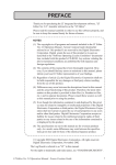
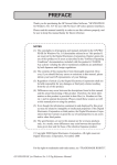
(1) The copyrights to all programs and manuals included in the GP-PRO/PB
III for Windows Ver. 6.3 (hereinafter referred to as "this product") are
reserved by the Digital Electronics Corporation. Digital grants the use of
this product to its users as described in the "Software Operating License
Conditions" documentation, included with this product's CD-ROM. Any
actions violating the above-mentioned conditions are prohibited by both
Japanese and foreign regulations.
(2) The contents of this manual have been thoroughly inspected. However, if
you should find any errors or omissions in this manual, please inform your
local GP representative of your findings.
(3) Regardless of article (2), the Digital Electronics Corporation shall not be
held responsible for any damages or third party claims resulting from the
use of this product.
(4) Differences may occur between the descriptions found in this manual and
the actual functioning of this product. Therefore, the latest information on
this product is provided in data files (i.e. Readme.txt files, etc. ) and in
separate documents. Please consult these sources as well as this manual
prior to using the product.
(5) Even though the information contained in and displayed by this product may
be related to intangible or intellectual properties of the Digital Electronics
Corporation or third parties, the Digital Electronics Corporation shall not
warrant or grant the use of said properties to any users and/or other third
parties.
(6) The specifications set out in this manual are for overseas products only. As a
result, some differences may exist between the specifications given here and
for those of the identical Japanese product. Digital Electronics Corporation
accepts no liability for issues related to the intellectual property rights of third
parties or any issues related to the use of the information contained in or
displayed by this product.
© Copyright 2003 Digital Electronics Corporation. All rights reserved.
Digital Electronics Corporation, September 2003
For the rights to trademarks and trade names, see “TRADEMARK RIGHTS”.
GP-PRO/PB III for Windows 6.3 Tag Reference Manual
1
TRADEMARK RIGHTS
TRADEMARK RIGHTS
All company or product names used in this manual are the trade names,
trademarks (including registered trademarks), or service marks of their
respective companies.
This product omits individual descriptions of each of these rights.
Trademark / Trade Name
Right Holder
Microsoft, MS, MS-DOS, Windows, Windows
95, Windows 98, Windows Me, Windows NT,
Windows 2000, Windows XP, Windows
Explorer, Microsoft Excel
Intel, Pentium
Microsoft Corporation, USA
Intel Corporation, USA
Pro-face
Digital Electronics Corporation
(in Japan and other countries)
Ethernet
Western Digital Electric Corporation, USA
IBM, VGA, IBM Compatible
International Business Machines Corporation
(IBM), USA
The following terms differ from the above mentioned formal trade names
and trademarks.
Term used in this manual
2
Formal Trade Name or Trademark
Windows 95
Microsoft® Windows®95 Operating System
Windows 98
Microsoft® Windows®98 Operating System
Windows Me
Microsoft® Windows®Me Operating System
Windows NT
Microsoft® Windows NT ® Operating System
Windows 2000
Microsoft® Windows®2000 Operating System
Windows XP
Microsoft® Windows®XP Operating System
GP-PRO/PB III for Windows Ver. 6.3 Tag Reference Manual
LIST OF SUPPORTED MODELS
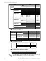
LIST OF SUPPORTED MODELS
The following table lists the models compatible with GP-PRO/PB III for Windows
Ver.6.3 The following series names or product names are used in the descriptions
contained in this manual.
List of Supported GPs
Series
Product
Name
GP-H70L
GP-H70 series
GP-H70S
Model
GPH70-LG11-24V
GPH70-LG41-24VP
GPH70-SC11-24V
GPH70-SC41-24VP
GP Type
GPH70L
GPH70S
GP270-LG11-24V
GP-270L
GP270-LG21-24VP
GP270L
GP270-LG31-24V
GP-270 series
GP270-SC11-24V
GP-270S
GP270-SC21-24VP
GP270S
GP270-SC31-24V
GP370-LG11-24V
GP-370L
GP370-LG21-24VP
GP370-LG31-24V
GP370L
GP370-LG41-24VP
GP-370 series
GP370-SC11-24V
GP-370S
GP370-SC21-24VP
GP370-SC31-24V
GP-370S
GP370-SC41-24VP
GP470-EG11
GP-470 series
GP-470E
GP70 series
GP470-EG21-24VP
GP470
GP470-EG31-24V
GP-570L
GP570-LG11-24V
GP570-LG21-24V
GP570L
GP570-SC11
GP-570S
GP570-SC21-24VP
GP570-SC31-24V
GP-570 series
GP570-TC11
GP-570T
GP570
GP570-TC21-24VP
GP570-TC31-24V
GP-571 series
GP-675 series
GP-870 series
GP-37W2 series
GP-57JS
GP57J-SC11
GP-570VM
GP570-TV11
GP570VM
GP-571T
GP571-TC11
GP571T
GP-675S
GP675-SC11
GP-675T
GP675-TC11
GP675
GP675-TC41-24VP
GP-870VM
GP870-PV11
GP870VM
GP-37W2B
GP37W2-BG41-24V
GP37W2
GP-377L
GP-377 series
GP-377S
GP-377R series
GP-377RT
GP-477R series
GP-477RE
GP77R series
GP-577RS
GP-577R series
GP-577RT
GP-PRO/PB III for Windows 6.3 Tag Reference Manual
GP377-LG11-24V
GP377-LG41-24V
GP377-SC11-24V
GP377-SC41-24V
GP377R-TC11-24V
GP377R-TC41-24V
GP477R-EG11
GP477R-EG41-24VP
GP377L
GP377S
GP377R
GP477R
GP577R-SC11
GP577R-SC41-24VP
GP577R-TC11
GP577R
GP577R-TC41-24VP
3
LIST OF SUPPORTED MODELS
Product
Name
Series
GP2000H
series
Model
GP Type
GP-2301HL
GP2301H-LG41-24V
GP2301HL
GP-2301HS
GP2301H-SC41-24V
GP2301HS
GP-2401HT
GP2401H-TC41-24V
GP2401H
GP-2300L
GP2300-LG41-24V
GP2300L
GP-2300S
GP2300-SC41-24V
GP2300S
GP-2300T
GP2300-TC41-24V
GP2300
GP-2301L
GP2301-LG41-24V
GP2301L
GP-2301S
GP2301-SC41-24V
GP2301S
GP-2301T
GP2301-TC41-24V
GP2301
GP-2400 series
GP-2400T
GP2400-TC41-24V
GP2400
GP-2401 series
GP-2401T
GP2401-TC41-24V
GP2401
GP-2500L
GP2500-LG41-24V
GP2500L
GP2500-SC41-24V
GP2500S
GP-2301H series
GP-2401H series
GP-2300 series
GP-2301 series
GP2000
series
GP-2500S
GP-2500 series
GP2500-TC11
GP-2500T
GP-2501 series
GP2500
GP2500-TC41-24V
GP-2501L
GP2501-LG41-24V
GP2501L
GP-2501S
GP2501-SC11
GP2501S
GP-2501T
GP2501-TC11
GP2501
GP-2600 series
GP-2600T
GP-2601 series
GP-2601T
GP2600-TC11
GP2600
GP2600-TC41-24V
GP2601-TC11
GP2601
List of Supported GLCs
Series
GLC100 series
GLC300 series
GLC2000 series
Product Name
GLC100L
GLC100 series
GLC100S
GLC300 series
GLC300T
GLC2300L
GLC2300 series
GLS2300T
GLC2400 series
GLC2400T
GLC2600 series
GLC2600T
Model
GP Type
GLC100-LG41-24V GLC100L
GLC100-SC41-24V GLC100S
GLC300-TC41-24V GLC300T
GLC2300-LG41-24V GLC2300L
GLC2300-TC41-24V GLC2300
GLC2400-TC41-24V GLC2400
GLC2600-TC41-24V GLC2600
List of Supported STs
Series
Product name
Model
GP Type
ST400
ST400-AG41-24V
ST400
ST401
ST401-AG41-24V
ST401
ST402
ST402-AG41-24V
ST402
ST400
series
List of Supported Factory Gateway
Product name
Factory Gateway
Model
FGW_SE41_24V
GP Type
Factory Gateway FGW-SE
To use the GPWeb and GPViewer functions with the Factory Gateway, you
must have GPPRO/PB III C-Package02 or later installed.
4
GP-PRO/PB III for Windows Ver. 6.3 Tag Reference Manual
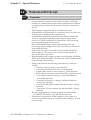
HOW TO USE THIS MANUAL
HOW TO USE THIS MANUAL
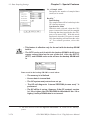
Structure of this Manual
The "Tag Reference manual" is the second of four manuals for this product, and
explains how to use the "GP-PRO/PB III for Windows Ver. 6.3" software (hereafter referred to as "this product"). Please refer to all of these manuals when using
this product.
In addition to these manuals, data files containing supplemental information on
updated functions are also provided.
To read these files, click on the [Start] button in your Windows OS main screen
and select the [Programs]→[Pro-face]→[ProPB3Win] menu. Then click on the
[Read Me] selection.
For detailed information about GP series products, please refer to each GP's
"User Manual" . (Optionally available)
Vol. 1
Vol. 2
Vol. 3
Vol. 4
Describes this product's operation
Operation Manual
procedures and all standard functions.
(provided as PDF data)
Tag Reference Manual Describes the functions and detailed settings
for all GP-PRO/PBIII Tags. (provided as
(This Manual)
PDF data)
Describes this product's pre-made Parts
Parts List
and symbols. (provided as PDF data)
Device/PLC Connection Describes the methods for connecting the
GP to other, supported manufacturer
Manual
Device/PLCs. (provided as PDF data)
Screen Data Layout Sheets are useful for designing tag address settings, etc.
and example sheets are installed as part of the GP-PRO/PBIII for Windows
standard installation.
The following two layout sheets, "Device Allocation Table" and "Tag Layout
Sheet", are in Microsoft Excel format and are located in the PDF Manual CDROM.
The following folder and file names are used.
Folder Name
File Name
Contents
Device Allocation Table
Pro-face\
propbwin\sheet
Device1E.xls
TAG1E.xls
TAG2E.xls
TAG3E.xls
TAG4E.xls
Tag Layout Sheet
For information on the use of Microsoft Excel, please refer to the Excel software's
User Manual.
Designation of Supported Models
The functions and settings supported by each model may vary depending on
the supported models. In this manual, explanations given are based on the
variation of the “Series” and “Product name” described in the “List of
Supported Models”.
GP-PRO/PB III for Windows 6.3 Tag Reference Manual
5
MANUAL SYMBOLS AND TERMINOLOGY
MANUAL SYMBOLS AND TERMINOLOGY
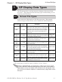
This manual uses the following symbols and terminology.
If you have any questions about the contents of this manual, please contact
your local GP distributor.
Also, If you have any question about your personal computer or Windows,
please contact your PC distributor or manufacturer.
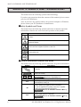
Safety Symbols and Terms
This manual uses the following symbols and terms to identify important
information related to the correct and safe operation of this product.
Symbol
Description
Indicates a potentially hazardous situation that could result in serious injury
or death.
Indicates a potentially hazardous situation that could result in minor injury or
equipment damage.
Indicates a potentially damaging action or dangerous situation that could
result in abnormal equipment operation or data loss.
Indicates instructions or procedures that must be performed to ensure
correct product use.
Indicates instructions or procedures that must not be performed.
General Information Symbols and Terms
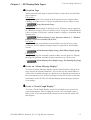
This manual uses the following symbols and terms for general information.
Symbol
Description
Provides hints on correct product use, or supplementary
information.
Esc
Ctrl
IBM Compatible
PLC
GP
Indicates an item's related information (manual name, chapter,
section, sub-section).
Refers to keys on the computer keyboard.
Keyboard Compatibility List
Indicates a PC that can run the Windows® operating system.
PLC (Programmable Logic Controller, sequencer), including
thermoregulator, inverter, etc.
Generic name for the "GP Series" of programmable operator
interface made by the Digital Electronics Corporation.
For a list of compatible GP products please see "Compatible
Products and Environmental Specifications".
LIST OF SUPPORTED MODELS List of
Supported GPs
GLC
6
Generic name for the GLC Series of Graphic Logic Controllers
made by Digital Electronic Corporation.
LIST OF SUPPORTED MODELS
Supported GLCs
List of
GP-PRO/PB III for Windows Ver. 6.3 Tag Reference Manual
WHEN USING GLC 2000 SERIES UNITS/WHEN USING ST SERIES UNITS
WHEN USING GLC2000 SERIES UNITS
GLC2000 Series units are equipped with the same features as GP2000 units,
with the addition of control-related features. As a result, please change the word
“GP” to “GLC” when reading this manual. However, please remember that GLC
Series units cannot use AUX output or Sound output.
Be sure to understand this manual thoroughly before using your GLC unit.
WHEN USING ST SERIES UNITS
In this manual, read the word “GP” (“GP2301L”) as “ST”. However, ST units
have certain restrictions owing to hardware specification differences with GP2301L units. Be sure to understand this manual thoroughly before using your ST
unit. Functions incompatible with your ST unit,
Operation
Manual [GENERAL GP RESTRICTIONS] section, Operation Manual
2.11.2 Restrictions
GP-PRO/PB III for Windows 6.3 Tag Reference Manual
7
TABLE OF CONTENTS
TABLE OF CONTENTS
PREFACE ............................................................................................ 1
TRADEMARK RIGHTS ....................................................................... 3
LIST OF SUPPORTED MODELS...................................................... 3
HOW TO USE THIS MANUAL ............................................................ 5
WHEN USING GLC2000 SERIES UNITS ........................................... 7
WHEN USING ST SERIES UNITS ...................................................... 7
TABLE OF CONTENTS ..................................................................... 8
1
GP Display Data Types
1.1
Screen File Types ...................................................................................................... 1-1
1.2
Active Image Functions ............................................................................................. 1-2
1.3
Tag List ( Alphabetical Order ) ................................................................................. 1-5
1.4
Tag List ( Function Order ) ........................................................................................ 1-8
1.5
Tag List of Support ................................................................................................... 1-12
1.6
Tag Setting Cautions ................................................................................................ 1-16
2
2.1
A-tag (Alarm Summary TEXT Display) ........................................................ 2-21
2.1.1
Overview .............................................................................................................. 2-21
2.1.2
About A-tags ........................................................................................................ 2-21
2.1.3
Using A-tags ......................................................................................................... 2-26
2.1.4
A-tag Example ...................................................................................................... 2-35
2.1.5
Color Settings ........................................................................................................ 2-38
2.2
8
Active Image Functions
a-tag (Alarm Summary Display) ..................................................................... 2-41
2.2.1
Overview .............................................................................................................. 2-41
2.2.2
About a-tags ......................................................................................................... 2-41
2.2.3
Using a-tags .......................................................................................................... 2-43
2.2.4
Alarm Summary Display Notes ............................................................................ 2-45
GP-PRO/PB III for Windows Ver. 6.3 Tag Reference Manual
TABLE OF CONTENTS
2.3
C-tag (Time Display) ....................................................................................... 2-47
2.3.1
Overview .............................................................................................................. 2-47
2.3.2
About C-tags ........................................................................................................ 2-47
2.3.3
Using C-tags ......................................................................................................... 2-49
2.4
D-tag (Statistical Graph Display) ................................................................... 2-51
2.4.1
Overview .............................................................................................................. 2-51
2.4.2
About D-tags ........................................................................................................ 2-51
2.4.3
Using D-tags ......................................................................................................... 2-52
2.5
d-tag (Statistical Data Display) ...................................................................... 2-55
2.5.1
Overview .............................................................................................................. 2-55
2.5.2
About d-tags ......................................................................................................... 2-55
2.5.3
Using d-tags .......................................................................................................... 2-57
2.6
E-tag (Extended N-tag Function) ..................................................................... 2-61
2.6.1
Overview ............................................................................................................... 2-61
2.6.2
About E-tags ......................................................................................................... 2-61
2.6.3
Using E-tags ......................................................................................................... 2-63
2.6.4
Indirect Word Addressing Examples .................................................................... 2-76
2.7
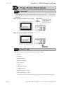
F-tag (Free Library Display) ......................................................................... 2-79
2.7.1
Overview .............................................................................................................. 2-79
2.7.2
About F-tags ......................................................................................................... 2-79
2.7.3
Using F-tags ......................................................................................................... 2-81
2.8
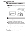
G-tag (Graph Display) ................................................................................... 2-85
2.8.1
Overview .............................................................................................................. 2-85
2.8.2
About G-tags ........................................................................................................ 2-84
2.8.3
Using G-tags ......................................................................................................... 2-86
2.9
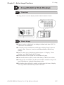
g-tag (Extended G-tag Function) ................................................................... 2-91
2.9.1
Overview .............................................................................................................. 2-91
2.9.2
About g-tags ......................................................................................................... 2-91
2.9.3
Using g-tags .......................................................................................................... 2-93
GP-PRO/PB III for Windows 6.3 Tag Reference Manual
9
TABLE OF CONTENTS
2.10
2.10.1
Overview .......................................................................................................... 2-101
2.10.2
About H-tag ...................................................................................................... 2-101
2.10.3
Using H-tags *1 ................................................................................................ 2-102
2.10.4
Object Drawing Data *1 .................................................................................. 2-104
2.11
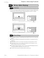
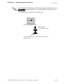
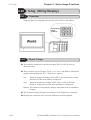
J-tag (Moving Mark Display) .................................................................... 2-109
2.11.1
Overview .......................................................................................................... 2-109
2.11.2
About J-tags ...................................................................................................... 2-109
2.11.3
Using J-tags ....................................................................................................... 2-111
2.12
K-tag (Key Input) ....................................................................................... 2-115
2.12.1
Overview .......................................................................................................... 2-115
2.12.2
About K-tags .................................................................................................... 2-115
2.12.3
Using K-tags ..................................................................................................... 2-118
2.12.4
Data Input Example .......................................................................................... 2-131
2.12.5
Notes on Entering BCD Data ........................................................................... 2-132
2.12.6
Auto Clear Example ......................................................................................... 2-134
2.12.7
Using Arithmetic Operations ............................................................................ 2-135
2.13
k-tag (Keyboard Setup) ............................................................................. 2-136
2.13.1
Overview .......................................................................................................... 2-136
2.13.2
About k-tags ..................................................................................................... 2-136
2.13.3
Using k-tags ...................................................................................................... 2-138
2.14
10
H-tag (Moving Mark Display) *1 .............................................................. 2-101
L-tag (Library Display) ............................................................................... 2-142
2.14.1
Overview .......................................................................................................... 2-142
2.14.2
About L-tags ..................................................................................................... 2-142
2.14.3
Using L-tags ..................................................................................................... 2-144
2.14.4
Library Display Coordinates ............................................................................. 2-147
2.14.5
Display Timing .................................................................................................. 2-149
2.14.6
Erase Mode Settings ......................................................................................... 2-150
2.14.7
Offset Settings .................................................................................................. 2-151
GP-PRO/PB III for Windows Ver. 6.3 Tag Reference Manual
TABLE OF CONTENTS
2.14.8
Notes on XOR Display ..................................................................................... 2-152
2.14.9
How to Avoid Overlapping Erase Images ........................................................ 2-153
2.14.10
2.15
Overlapping Colors on a Color GP ................................................................ 2-154
l-tag <small L> (Library Status Display) ................................................... 2-160
2.15.1
Overview .......................................................................................................... 2-160
2.15.2
About l-tags ...................................................................................................... 2-161
2.15.3
Using l-tags ....................................................................................................... 2-162
2.15.4
Bit Offset and Bit Length Settings ................................................................... 2-164
2.16
M-tag (Mark Display) ............................................................................... 2-166
2.16.1
Overview .......................................................................................................... 2-166
2.16.2
About M-tags .................................................................................................... 2-166
2.16.3
Using M-tags .................................................................................................... 2-168
2.16.4
Mark Display Using Indirect Mode .................................................................. 2-170
2.17
N-tag (Numeric Display) ............................................................................ 2-172
2.17.1
Overview .......................................................................................................... 2-172
2.17.2
About N-tags .................................................................................................... 2-172
2.17.3
Using N-tags ..................................................................................................... 2-174
2.17.4
Relative Data Display Settings ......................................................................... 2-180
2.18
n-tag (Alarm Range Display) ..................................................................... 2-182
2.18.1
Overview .......................................................................................................... 2-182
2.18.2
About n-tags ..................................................................................................... 2-182
2.18.3
Using n-tags ...................................................................................................... 2-183
2.19
P-tag (Numeric Display in Pre-designated Format) .................................. 2-186
2.19.1
Overview .......................................................................................................... 2-186
2.19.2
About P-tags ..................................................................................................... 2-186
2.19.3
Using P-tags ..................................................................................................... 2-188
2.19.4
P-tag Example Settings ..................................................................................... 2-192
2.20
Q-tag (Alarm Summary Display) ................................................................ 2-194
2.20.1
Overview .......................................................................................................... 2-194
GP-PRO/PB III for Windows 6.3 Tag Reference Manual
11
TABLE OF CONTENTS
2.20.2
About Q-tags .................................................................................................... 2-194
2.20.3
Q-tag Restrictions ............................................................................................. 2-199
2.20.4
Using Q-tags ..................................................................................................... 2-200
2.20.5
Q-tag Examples ................................................................................................ 2-207
2.20.6
Sub Display Example ........................................................................................ 2-209
2.20.7
About Freeze Mode ......................................................................................... 2-212
2.20.8
Roll Up and Roll Down Keys ........................................................................... 2-213
2.20.9
GP System Area Q-tag settings ....................................................................... 2-214
2.20.10
2.21
R-tag (Rail Settings) ................................................................................... 2-226
2.21.1
Overview .......................................................................................................... 2-226
2.21.2
About R-tags ................................................................................................... 2-226
2.21.3
Using R-tags ..................................................................................................... 2-227
2.22
S-tag (String Display) .................................................................................. 2-230
2.22.1
Overview .......................................................................................................... 2-230
2.22.2
About S-tags .................................................................................................... 2-230
2.22.3
Using S-tags ...................................................................................................... 2-232
2.23
T-tag (Touch Panel Input) .......................................................................... 2-236
2.23.1
Overview .......................................................................................................... 2-236
2.23.2
About T-tags ..................................................................................................... 2-236
2.23.3
Using T-tags ..................................................................................................... 2-239
2.23.4
One-Shot Buzzer for T-tag momentary ............................................................ 2-248
2.23.5
Setting Up T-tags .............................................................................................. 2-250
2.23.6
Changing Screens ............................................................................................. 2-251
2.23.7
Screen Level Change Direction ........................................................................ 2-255
2.24
12
Example of CSV Storage of Q-tag Alarm Summary .................................... 2-224
t-tag (Selector Switch Input) ...................................................................... 2-258
2.24.1
Overview .......................................................................................................... 2-258
2.24.2
About t-tags ...................................................................................................... 2-258
2.24.3
Using t-tags ....................................................................................................... 2-260
GP-PRO/PB III for Windows Ver. 6.3 Tag Reference Manual
TABLE OF CONTENTS
2.25
Tih / Tiw-tags (Inching Function) * ............................................................. 2-262
2.25.1
Overview .......................................................................................................... 2-262
2.25.2
About Tih / Tiw-tags ......................................................................................... 2-263
2.25.3
Using Tih-tags * ................................................................................................ 2-264
2.25.4
Using Tiw-tags .................................................................................................. 2-265
2.26
U-tag (Window Display) ............................................................................. 2-266
2.26.1
Overview ........................................................................................................... 2-266
2.26.2
About U-tags .................................................................................................... 2-266
2.26.3
Global Window Display ..................................................................................... 2-268
2.26.4
Local Window Display ...................................................................................... 2-269
2.26.5
Using U-tags ..................................................................................................... 2-270
2.26.6
U-tag Examples ................................................................................................ 2-272
2.26.7
GP System Area Global Window Display Settings .......................................... 2-273
2.27
V-tag (Video Window Display) ................................................................... 2-274
2.27.1
Overview .......................................................................................................... 2-274
2.27.2
About V-tags .................................................................................................... 2-274
2.27.3
Using V-tags * ................................................................................................. 2-276
2.27.4
V-tag Examples * ............................................................................................. 2-279
2.28
v-tag (Extended Video Window Display) ................................................... 2-281
2.28.1
Overview .......................................................................................................... 2-280
2.28.2
About v-tags ..................................................................................................... 2-280
2.28.3
Using v-tags ...................................................................................................... 2-285
2.28.4
v-tag Examples ................................................................................................. 2-286
2.29
W-tag (Write to Device) ............................................................................ 2-291
2.29.1
Overview .......................................................................................................... 2-291
2.29.2
About W-tags .................................................................................................... 2-292
2.29.3
Using W-tags .................................................................................................... 2-293
2.29.4
W-tag Examples ............................................................................................... 2-297
GP-PRO/PB III for Windows 6.3 Tag Reference Manual
13
TABLE OF CONTENTS
2.30
X-tag (Display Text Data) ......................................................................... 2-298
2.30.1
Overview .......................................................................................................... 2-298
2.30.2
About X-tags .................................................................................................... 2-298
2.30.3
Using X-tags ..................................................................................................... 2-300
2.30.4
X-tag Examples ................................................................................................ 2-303
2.31
Trend Graph Display ................................................................................... 2-306
2.31.1
Overview .......................................................................................................... 2-306
2.31.2
About Trend Graphs ......................................................................................... 2-306
2.31.3
Using Trend Graphs .......................................................................................... 2-309
2.31.4
Channel Settings ............................................................................................... 2-318
2.31.5
Block Display Mode ( for PLC Direct Access ) ............................................. 2-321
2.31.6
Principles of Historical Function ....................................................................... 2-325
2.31.7
Trend Graph Data’s CSV File Storage Example .............................................. 2-331
3
3.1
D-Script / Global D-Script ................................................................................. 3-1
3.1.1
Overview ................................................................................................................ 3-1
3.1.2
About D-Script ....................................................................................................... 3-1
3.1.3
Using D-Script ........................................................................................................ 3-5
3.1.4
D-Script / Global D-Script Limitations ................................................................. 3-62
3.1.5
Notes on Operation Results .................................................................................. 3-66
3.1.6
Logical Operation Examples ................................................................................. 3-67
3.1.7
Bit Operation Examples ........................................................................................ 3-68
3.1.8
Conditional Branches ............................................................................................ 3-69
3.1.9
Application Example (1) ....................................................................................... 3-70
3.1.10
Application Example (2) ..................................................................................... 3-73
3.1.11
Extended SIO Data Transfer Settings ............................................................... 3-74
3.2
14
Special Features
Extended SIO Script ....................................................................................... 3-93
3.2.1
Overview .............................................................................................................. 3-93
3.2.2
Details ................................................................................................................... 3-94
GP-PRO/PB III for Windows Ver. 6.3 Tag Reference Manual
TABLE OF CONTENTS
3.2.3
Setting Parameters ............................................................................................... 3-99
3.2.4
Example Communication Using Extended SIO .................................................. 3-160
3.3
Data Sampling Settings ................................................................................. 3-172
3.3.1
Overview ............................................................................................................ 3-172
3.3.2
About Data Sampling Settings ............................................................................ 3-172
3.3.3
Using Channel Settings ....................................................................................... 3-173
3.3.4
Data Sampling CSV File Storage Example .................................................... 3-177
4
4.1
Advanced Features
Sound Output ..................................................................................................... 4-1
4.1.1
Overview ................................................................................................................ 4-1
4.1.2
About Sound Output ............................................................................................... 4-1
4.1.3
Sound Output Settings ............................................................................................ 4-2
4.1.4
Sound Output Setting Examples ............................................................................. 4-4
4.1.5
Sound Data Output ................................................................................................. 4-8
4.2
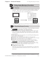
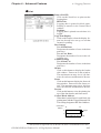
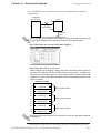
Filing Data (Recipe) Function ......................................................................... 4-13
4.2.1
Overview .............................................................................................................. 4-13
4.2.2
Filing Data (Recipe) Function .............................................................................. 4-12
4.2.3
Filing Data Setting .................................................................................................. 4-21
4.2.4
Filing Data List ..................................................................................................... 4-25
4.2.5
Filing Data Setup .................................................................................................. 4-37
4.2.6
Automatic Filing Data Transmission ..................................................................... 4-36
4.2.7
Manual Filing Data Transmission Example 1 ....................................................... 4-38
4.2.8
Manual Filing Data Transmission Example 2 ....................................................... 4-45
4.3
Logging Function ............................................................................................. 4-49
4.3.1
Logging Function .................................................................................................. 4-51
4.3.2
Logging Data Read Timing ................................................................................... 4-55
4.3.3
Using the Logging Function .................................................................................. 4-57
4.3.4
Display Settings .................................................................................................... 4-70
4.3.5
Print Settings ......................................................................................................... 4-81
GP-PRO/PB III for Windows 6.3 Tag Reference Manual
15
TABLE OF CONTENTS
4.3.6
Excel Display of Logging Data ............................................................................ 4-92
4.3.7
Data Logging Display Usage Example ................................................................ 4-95
4.3.8
Economy Mode ................................................................................................ 4-100
4.4
4.4.1
Overview ............................................................................................................ 4-105
4.4.2
Details ................................................................................................................. 4-107
4.4.3
List of Condition Settings .................................................................................... 4-108
4.4.4
Condition Setting .................................................................................................. 4-111
4.4.5
CSV File List ...................................................................................................... 4-114
4.4.6
Automatic Transfer Operation on the GP .......................................................... 4-116
4.4.7
Manual Transfer Operation on the GP ............................................................... 4-137
4.4.8
Example of Automatic Transfer for Filing Application (Conditional Operation) 4-140
4.4.9
Example of Automatic Transfer for Filing Application (Address Operation) .... 4-144
4.4.10
Example of Manual Transfer for Filing Application ......................................... 4-149
4.4.11
Example of Transfer for Logging Application (1) ............................................. 4-150
4.4.12
Example of Transfer for Logging Application (2) ............................................ 4-152
4.5
CSV Data Display Function .......................................................................... 4-158
4.5.1
Overview ............................................................................................................ 4-158
4.5.2
Details ................................................................................................................. 4-158
4.5.3
Setting Parameters ............................................................................................. 4-158
4.5.4
CSV Data Display (Combination) ...................................................................... 4-162
4.5.5
CSV Data Editing Function ................................................................................ 4-167
4.5.6
Printing CSV Data ............................................................................................... 4-169
4.6
16
CSV Data Transfer Function ........................................................................ 4-105
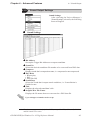
File Manager Display Function .................................................................... 4-171
4.6.1
Overview ............................................................................................................ 4-171
4.6.2
Details ................................................................................................................. 4-171
4.6.3
Setting Parameters ............................................................................................. 4-173
4.6.4
File Manager Display Function ........................................................................... 4-175
GP-PRO/PB III for Windows Ver. 6.3 Tag Reference Manual
TABLE OF CONTENTS
4.7
Using the CF Card ......................................................................................... 4-180
4.7.1
Overview ............................................................................................................ 4-180
4.7.2
CF Card Features ............................................................................................... 4-181
4.7.3
CF Card Usage Cautions .................................................................................... 4-180
4.7.4
External Storage of GP-PRO/PB III data ......................................................... 4-182
4.7.5
CF Card Data Output Folder Settings ................................................................ 4-185
4.7.6
Transferring Data from Output Folder to CF Card ............................................ 4-184
4.7.7
Using the GP’s OFFLINE Mode ......................................................................... 4-185
4.7.8
Transferring Data from Backup SRAM to CF Card ......................................... 4-187
4.7.9
Making a Backup of Backup SRAM ................................................................. 4-191
4.7.10
Screen Capture ................................................................................................. 4-197
4.7.11
Checking the CF Card’s Available Capacity .................................................... 4-205
4.8
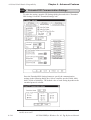
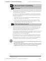
Serial-Code Reader Compatibility ............................................................... 4-206
4.8.1
Overview ............................................................................................................ 4-206
4.8.2
Compatible Serial-Code Readers ....................................................................... 4-207
4.8.3
Outline of Operation ........................................................................................... 4-207
4.8.4
Action Settings .................................................................................................... 4-206
4.8.5
GP System Settings ........................................................................................... 4-213
4.8.6
LS Storage Start Address Settings .................................................................... 4-213
4.8.7
Extended Settings .............................................................................................. 4-212
4.8.8
Extended SIO Communication Settings ............................................................ 4-214
4.9
Bar-Code Reader Compatibility ................................................................... 4-215
4.9.1
Overview ............................................................................................................ 4-215
4.9.2
Bar-Code Reader Features ................................................................................ 4-214
4.9.3
Tested Bar Code Readers .................................................................................. 4-217
4.10
256-color Mode ........................................................................................... 4-229
4.10.1
Overview .......................................................................................................... 4-228
4.10.2
256-color Mode Correspondence ..................................................................... 4-228
4.10.3
Monochrome (eight levels of gray) mode .......................................................... 4-230
GP-PRO/PB III for Windows 6.3 Tag Reference Manual
17
TABLE OF CONTENTS
4.11
Backup SRAM Capacity ............................................................................ 4-232
4.11.1
Overview .......................................................................................................... 4-233
4.11.2
Backup SRAM Amounts for each type of GP ................................................ 4-233
4.11.3
Backup SRAM Applications ............................................................................ 4-233
4.12
Extended Functions of VM Unit ................................................................. 4-235
4.12.1
Displaying Video Window ................................................................................. 4-235
4.12.2
Video Control Area ........................................................................................... 4-236
4.12.3
Standard Mode ................................................................................................. 4-237
4.12.4
Extended Mode ................................................................................................. 4-242
4.12.5
Video Control Area Example ............................................................................ 4-250
4.12.6
Vide Control Area Settings ............................................................................... 4-261
4.12.7
VGA/SVGA Display Function ......................................................................... 4-267
4.12.8
Converting GP-530VM/GP-570VM Screens ................................................... 4-269
Index
18
GP-PRO/PB III for Windows Ver. 6.3 Tag Reference Manual
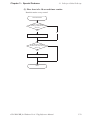
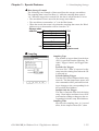
Chapter 1 - GP Display Data Types
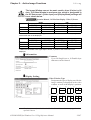
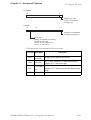
1
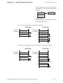
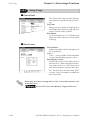
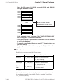
1.1 Screen File Types
GP Display Data Types
The GP unit provides a real-time interactive display of data stored in the
host (PLC). This chapter describes the many types of functionality you can
create on your GP’s screen.
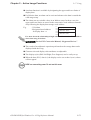
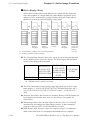
1.1
Screen File Types
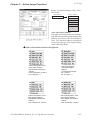
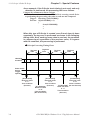
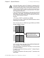
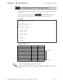
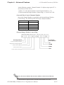
Please look at the following list of GP file/screen types. This program
utilizes six types of files/screens, each of which has a different purpose.
Screen Type
Screen File
Number
Base Screen
(B file)
B1 - B8999
Mark Screen
(M file)
M1 - M8999
Trend Graph
screen
(T file)
Keyboard
screen
(K file)
T1 - T8999
K1 - K8999
Text screen
(X file)
X1 - X8999
Image Library
screen (I file)
I1 - I8999
Video screen
(V file)
V1 to V512
Window screen
(U file)
U1 to U2000
Description
Appears on the GP display while the GP is operating.
Objects used as either a static graphic or in a moving image
can be called up from other Base screens and used like
building blocks. Base screen objects can be also registered
as a window, which can then be opened temporarily on
another screen.
Displays user-created dot-based marks or symbols up to a
maximum of 48 x 48 pixels. These marks can be either fixed
or moving images on the Base screens.
Displays graph axes and graduations, and sets the
parameters used for trend graphs. This screen can be
called up and used on a Base screen.
Displays a keypad, which is used for entering alphanumeric
characters or symbols. This screen can be called up and
used on a Base screen.
Displays only text, or character data. A Text screen can be
created by entering characters directly, or by pasting text
data previously edited with a text editor. This screen is used
with screens that contain moving images.
Contains graphic images converted from bitmap data. Image
screens can be either fixed, or used with Base screens that
contain moving images.
This screen is used to set the display of video input. Images
can be used from video cameras, PC monitors or JPEG
files.
This screen is used for making Window settings. Windows
created on the Base screen or Window screen are called
up and displayed on the Base screen.
Maximum
Screen Size
Approx. 16 KB
Approx. 576
bytes
Approx. 16 KB
Approx. 16 KB
Approx. 53 KB
Approx. 58 KB
Approx. 16 KB
Approx. 16 KB
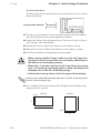
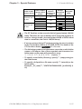
The initial letter of each file’s name is called its “Screen Header.”
With the GP-PRO/PB III, even though up to 8,999 screens can be created
for each of the above mentioned file types (up to 512 video screens and up to
2000 window screens), the number of files storable in the GP depends on the
size of each screen and the computer’s available memory, floppy disk or hard
disk space.
GP-PRO/PB III for Windows Ver. 6.3 Tag Reference Manual
1-1
Chapter 1 - GP Display Data Types
1.2 Active Image Functions
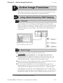
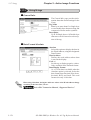
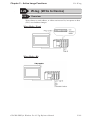
1.2
Active Image Functions
The GP displays data from the host (PLC) in real time, using pictures, text,
and graphic images the user has created via the GP-PRO/PBIII drawing
software. The GP also has touch panel keys which, together with these
functions, send the data you enter to the host (PLC). These functions are
referred to as “Active Image” functions. When using Active Image screens,
information such as which data in the host (PLC) to use, data’s format and
location on the screen, must all be defined in advance and stored in the GP.
These Active Image screens change the GP panel from a simple display
monitor to an intelligent and valuable operation panel.
Wide Range of Functions
Active Image type display functions include 23 different kinds of pre-made
“Parts” and 31 different kinds of “Tags,” as well as an “Alarm Message
Display,” “Trend Graph Display”, “D Script”,“Extended SIO Script”, “Data
Sampling Settings”, as well as “CSV Data Transfer Function”, “Filing Data
Function”, “Logging Function”, and “Sound Output” which all widen the
application usage.
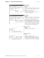
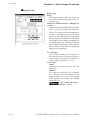
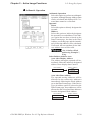
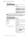
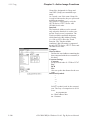
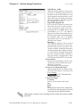
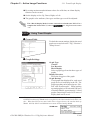
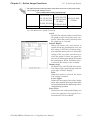
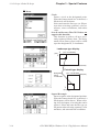
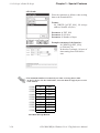
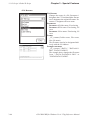
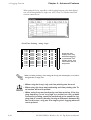
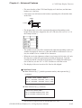
“Parts”, seen in the GP-PRO/PBIII Editor screen’s right side icon box, are a
collection of pre-made, often used object’s icons.
Creating an Active Image display is easy. Simply click on the type of Part
you wish to use, designate the necessary PLC addresses, and position the
item on your current screen. This simplicity greatly reduces the amount of
time required to create and edit a given screen.
“Tags”, which are explained in detail in this manual, are useful for when
you wish to create unique, original screens. This manual has been created
expressly to explain the types of Tags available, and how they can add
useful object movement functionality to your GP unit’s applications.
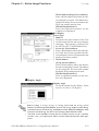
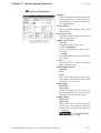
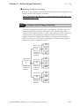
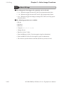
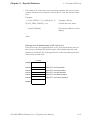
Creating Active Images
Use your screen editing software, GP-PRO/PB III for Windows, to create
project files containing Active Image screens. This project file will then be
downloaded to the GP, together any necessary system data. The GP will
then use this information to communicate with the host (PLC).
1-2
GP-PRO/PB III for Windows Ver. 6.3 Tag Reference Manual
Chapter 1 - GP Display Data Types
1.2 Active Image Functions
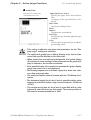
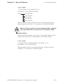
Exception Tags
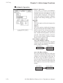
While most Parts and Tags are placed on Base screens, there are the following exceptions:
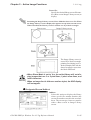
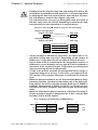
Exception 1:
k-tags are normally, first, placed on the Keyboard screens, and then later,
called up on a Base screen. (Can also be placed directly on a Base screen)
k-tag (Keyboard Setup)
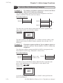
Exception 2:
U-tags are normally placed on the Base screen. Windows can be registered
in a Window screen (U file) or in a Base screen. U-tags for Global Windows
can be set in the “GP System”, and the window’s display is controlled in the
System Area.
Window Display (U-tag), Operation Manual , 3.7 Window
Display: (U) Screen and Base (B) Screen
Exception 3:
a-tags and Q-tags are normally created on Base screens, however, some
parameters such as display messages must be registered on Alarm Editor
screens.
Alarm Summary Display (a-tag), Alarm History Display (Q-tag)
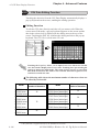
Exception 4:
A-tags and X-tags are normally created on Base screens, however, Display
Message Registration and other features must be set in a Text screen.
Alarm Summary (Text) Display (A-tag), Text Data Display (X-tag)
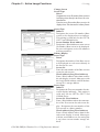
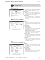
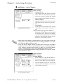
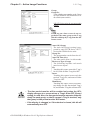
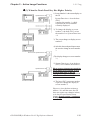
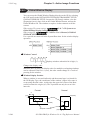
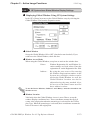
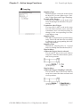
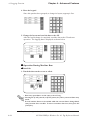
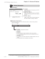
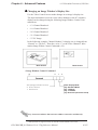
Create an “Alarm Message Display”
To create an Alarm Message display, use the Alarm Editor to edit the messages and set the related parameters. You can also use the Alarm Editor to
set the order in which messages are displayed or to display the messages in
the order that they occur. After all settings are entered, save the screen and
download it to the GP. The GP will then display alarm messages based on
your settings.
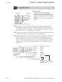
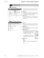
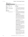
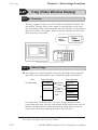
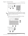
Create a “Trend Graph Display”
To create a Trend Graph display, use the Trend Graph screen to enter the
required parameters. After creating the screen, save it and load it onto a
Base screen. Next, download all the related screens to the GP, which will
then display.
GP-PRO/PB III for Windows Ver. 6.3 Tag Reference Manual
1-3
1.2 Active Image Functions
Chapter 1 - GP Display Data Types
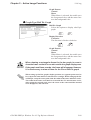
D-Script Reduces Your PLC Programming
“D-Script” programs are created via the D-Script editor. As a substitution to the PLC ladder program for display, language type script programming (D-Script) can be used to create a display program. Thus, the
GP can perform data processing internally, thereby reducing the PLC’s
processing load.
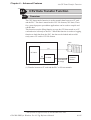
Communicate with Extended SIO (Extended serial interface)
via the Extended SIO Script
The “Extended SIO Script” is a D-Script dedicated to communication
between the Extended SIO (extended serial interface) built into the GP and
the I/O device connected to the GP.
The Extended SIO Script will function as program-independent from the tag
processing on the screen.
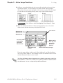
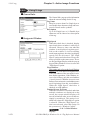
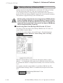
Register “Filing Data” via the Filing Data List
Use the Filing Data List to register filing data. The filing data function
represents a function to register set values, such as recipes as files to the GP
and to send those values to the PLC devices due to an event, etc. This Filing
Data is stored in either the GP’s internal memory or in a CF card. To send
Filing Data to a PLC, place a File Name Display and select the desired data
to be sent.
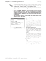
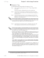
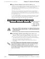
Log PLC Data Using the “Logging Function”
Using the “Logging Function”, PLC device data is logged and stored in the
back-up SRAM via the settings registered as the “Logging Settings”. This
logged data can also be stored on a CF card.
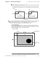
Register Sounds via “Sound Data”
Previously created “Sound Data” is registered in the GP as sound data.
This data can be stored in the GP’s internal memory or on a CF card.
Sounds are then output from a speaker using the settings registered in the
sound settings area.
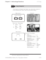
Transfer data files in CSV format using CSV Data Transfer
Function
The CSV Data Transfer Function enables the transfer of data in CSV file
format (CSV data) between the CF Card and PLC. Since the data are transferred in the form of a CSV file, data creation and editing can be performed
with general-purpose spreadsheet software.
1-4
GP-PRO/PB III for Windows Ver. 6.3 Tag Reference Manual
Chapter 1 - GP Display Data Types
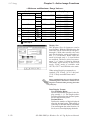
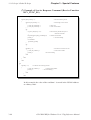
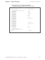
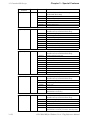
1.3
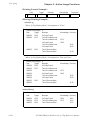
1.3 Tag List (Alphabetical Order)
Tag List ( Alphabetical Order )
Tag Names
Alarm Summary
TEXT Display
(A-tag)
Alarm Summary
Display (a-tag)
Time Display
(C-tag)
Description
Comments
Displays text messages registered on Text screens in rows,
according to the host's (PLC's) bit address data changes. The
*1
desired rows can be displayed in an Alarm Summary. Using
combinations of other tags, sub screens corresponding to each
message can also be displayed.
Lists the alarm messages registered in the Alarm Editor, according to
*1
the host's (PLC's) bit address data changes.
Displays the time, based on the GP's internal clock.
Displays a statistical graph, which represents data in the host's
(PLC's) consecutive related word addresses as percentages of a
total.
Statistical Data
Displays numeric values according to the data in the host's (PLC's)
Display (d-tag)
consecutive related word addresses.
Numeric Data
Displays numeric data in real time, as the data in the host's (PLC's)
Display (expandword address changes. The color of the display can be set to show
ed N-tag function)
movement within preset data ranges. Data can be displayed in
(E-tag)
decimal, hexadecimal, BCD, binary, octal, and floating-point format.
Brings up a library object in the position designated by the PLC word
"Free" Library
address data. The object may then be moved to any position on the
Display (F-tag)
GP display.
Graph Display
Uses bar, pie, or half-pie graphs to display host (PLC) word
(G-tag)
address data in real time.
Graph Display
Uses bar, pie, or half-pie graphs to display host (PLC) word
(expanded G-tag function) address data in real time. The color of the display can be set to show
(g-tag)
movement within preset data ranges.
Object Drawing
Draws objects such as straight lines, rectangles circles, etc. at the
(H-tag)
desired screen coordinates using host (PLC) Word Address data.
Moving Mark
Places an object and moves it along a preset rail (created by an RDisplay (J-tag)
tag). (Use in conjunction with the R-tags.)
Allows you to enter character or numeric data through either a touch
Key Input
keyboard (set up via k-tags), a barcode reader, or a standard PC
(K-tag)
keyboard. This data is stored in the host's (PLC's) designated word
address.
Provides a touch keyboard for inputting data settings to touch panel
Keyboard
Setup (k-tag)
switches. Use in combination with the K-tags.
Displays Base or Image Library screen objects or text previously
Library Display
registered in libraries. These items will be either displayed or not
(L-tag)
displayed, according to the host's (PLC's) data.
A variety of Base or Image Library screen data previously
Library State Change
registered as library items can be set to appear whenever there is a
Display
change in the hosts (PLCs) word device data, activates a response.
( l [small L] -tag)
This is a special L-tag function.
Mark Display
Marks, which are bit-mapped icon images created in Mark screens,
(M-tag)
are used on Base screens to reflect changes in host (PLC) data.
Statistical Graph
Display (D-tag)
GP-PRO/PB III for Windows Ver. 6.3 Tag Reference Manual
*4
*1
*1
1-5
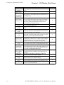
1.3 Tag List (Alphabetical Order)
Tag Names
Numeric Display
(N-tag)
Alarm Boundary
Display (n-tag)
Numeric Display
in Pre-defined
Format (P-tag)
Chapter 1 - GP Display Data Types
Description
Used to display a numeric value from the host's (PLC's) word
address.
Displays the upper and lower limits of the alarm range set in K-tags.
Displays host (PLC) word address data as an absolute value, using
a pre-defined format.
Lists alarm messages registered in the Alarm Editor in historical
order, and in response to host (PLC) bit changes. The messages in
Alarm Summary
the summary display can be listed as either active, history, or log.
Display (Q-tag)
When used in combination with other tags, messages can be
checked, deleted, sub-displayed and so on.
Rail Settings
Defines the rail (track) along with a preset Mark (set via a J-tag)
(R-tag)
moves. Used together with the J-tag.
String Display
Displays character string data stored in the host's (PLC's) word
(S-tag)
address.
T-tags interpret touch area on the Graphic Panel for the host (PLC).
Touch Panel Input
When the user presses one of these defined touch area, the action
(T-tag)
defined by the associated T-tag is performed.
Provides a touch panel object which looks and operates like a
Selector Switch Input
selector switch. Each time the object "switch" is pressed, one switch
(t-tag)
address turns OFF and another address bit turns ON.
Sends "inching output" from the touch panel (GP) directly to a digital
Inching Function input (DIN) relay on the host (PLC) via the GP's AUX I/O interface
(Tih and Tiw tags) (hereafter referred to as "AUX I/F". This allows instantaneous fine
adjustment to be performed, using just the touch panel keys.
Window Display In response to host (PLC) word address changes, this function
(U-tag)
places a window screen over the currently displayed Base screen.
This tag is supported by the GP-570VM and GP-870VM units, and
Video Window
the GP2500/2600 series units (with optional VM unit attached). This
Display (V-tag)
tag lays a special window screen, used for displaying video input
data, over the currently displayed Base screen.
Extended Video For use with GP-2500/GP-2600 Series interfaces. Requires
Window Display attachment of optional VM unit. Displays video input screens on a
(v-tag)
Base screen.
Write to Device
Writes data to a word address, or either sets or resets a bit in
(W-tag)
response to host (PLC) word address changes.
Display Text Data Displays text data (only characters) registered on a Text screen in
(X-tag)
response to host (PLC) word address changes.
Alarm Message In response to changes in the host's (PLC's) bit address, lists alarm
Display
messages registered in the Alarm Editor at the bottom of the screen.
Displays a trend graph that shows the change of a value overtime in
Trend Graph Display
the host's (PLC's) word address data.
1-6
Comments
*1
*1
*4
*1
*1
*2
*1
*1
*1
GP-PRO/PB III for Windows Ver. 6.3 Tag Reference Manual
Chapter 1 - GP Display Data Types
Tag Names
1.3 Tag List (Alphabetical Order)
Description
Comments
Design your own program and execute it on the GP to provide additional display
functions. D-Script programs also help to reduce the PLC's data display load.
D-Script dedicated to communication between the Extended SIO (extended serial
Extended SIO Script
interface) built into the GP and the I/O device connected to the GP.
Data Sampling Settings Designated Word Address data can be stored in the LS Area in time series order.
D-Script
*3
*4
CSV Data Transfer
Function
Sound Output
Filing data such as the previously registered recipe data can be sent to the PLC as
desired.
Logs and stores the PLC's data to the backup SRAM periodically or when the PLC
triggers. Also, the logged data can be stored in a CF card.
Data files can be transferred between the CF Card and PLC in CSV format (CSV
data).
Sounds are output according to the host's bit changes.
*7
Vibration
Runs the internal motor and vibrates the GP. (Vibration function)
*8
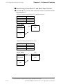
Filing Data Function
Logging Function
*5
*5
*6
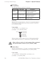
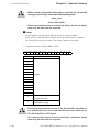
*1 Contains items whose functions change according to the GP’s screen size and installation orientation (i.e. portrait or landscape).
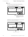
Chapter 2 Active Image Functions
*2 GP-270, GP-370, GP-H70, GP-377, GP-377R , GP37W2 and GP-2000 Series units do
not support this feature.
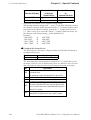
1.5 Tag List of Support
*3 Available only with GP2000 Series units featuring built-in Extended SIO (Excluding
GP-2301, GP-2401, GP-2501 and GP-2601 Series).
*4 GP-270 does not support this feature.
1.5 Tag List of Support
*5 Available only with the GP77R, GP-377 and GP2000 Series units. The CF card interface comes standard with the GP2000 Series units. When attaching the multi unit to the
GP77R units, the CF card can be used. The CF card cannot be used with the GP-377
Series units.
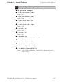
Operation Manual, Functions for GP-PRO/PBIII for Windows to
Ver. 6.2
*6 This function is supported only by GP2000 Series units
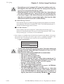
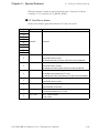
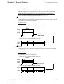
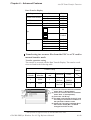
*7 This feature is available only with GP-477R, GP-577R, and GP2000 Series units (except GP-2300, GP-2301, and GP2000H Series units). An optional Multi Unit (sold separately) is required for outputting sound data from the GP with GP-477R, GP-577R, GP2401, GP-2501 and GP-2601 Series units.
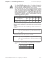
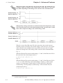
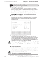
Feature
GP2000 Series
(except
GP-2300/2301/2000H)
GP-2501, GP-2601
Series
+
Large-size Multi Unit
(bus conversion unit)
GP-477R/577R
+
Large-size Multi Unit
Sound Output
*8 This function is supported only by GP2000H Series units (excluding GPH70 compatible
mode).
GP-PRO/PB III for Windows Ver. 6.3 Tag Reference Manual
1-7
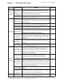
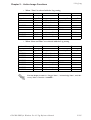
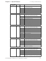
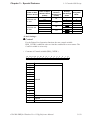
1.4 Tag List (Function Order)
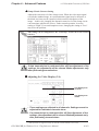
1.4
Screen
Operation
Touch
Switch
Numeric
Display
Chapter 1 - GP Display Data Types
Tag List ( Function Order )
Function
Name
Outline
Comments
k-tag (Key board Provides a touch keyboard for inputting data settings to touch panel
Setup)
switches. Use in combination with the K-tags.
*1
T-tag (Touch
Panel Input)
T-tags interpret touch area on the Graphic Panel for the host (PLC).
When the user presses one of these defined touch areas, the action
defined by the associated T-tag is performed.
*1
t-tag (Selector
Switch Input)
Provides a touch panel object which looks and operates like a
selector switch. Each time the object "switch" is pressed, one switch
address turns OFF and another address bit turns ON.
*1
Tih and Tiw
tags (Inching
Function)
Sends "inching output" from the touch panel (GP) directly to a digital
input (DIN) relay on the host (PLC) via the GP's AUX I/O interface
(here after referred to as "AUX I/F"). This allows instantaneous fine
adjustment to be performed, using just the touch panel keys.
*2
C-tag
(Time Display)
Displays the time, based on the GP's internal clock.
E-tag (Numeric
Data Display:
expanded
N-tag function)
Displays numeric data in real time, as the data in the host's (PLC's)
word address changes. The color of the display can be set to show
movement within preset data ranges. Data can be displayed in
decimal, hexadecimal, BCD, binary, octal, and floating-point format.
K-tag
(Key Input)
Allows you to enter character or numeric data through either a touch
keyboard (set up via k-tags), a barcode reader, or a standard PC
keyboard. This data is stored in the host's (PLC's) designated word
address.
N-tag (Numeric
Display)
*1
Used to display a numeric value from the host's (PLC's) word
address.
n-tag (Alarm
Displays the upper and lower limits of the alarm range set in K-tags.
Boundary Display)
P-tag (Numeric
Display in Predefined Format)
Displays host (PLC) word address data as an absolute value, using
a pre-defined format.
D-tag (Statistical Displays a statistical graph, which represents data in the host's (PLC's)
Graph Display) consecutive related word addresses as percentages of a total.
Graph
Display
d-tag (Statistical
Data Display)
Displays numeric values according to the data in the host's (PLC's)
consecutive related word addresses.
G-tag
Uses bar, pie, or half-pie graphs to display host (PLC) word address
(Graph Display) data in real time.
1-8
GP-PRO/PB III for Windows Ver. 6.3 Tag Reference Manual
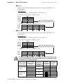
Chapter 1 - GP Display Data Types
Screen
Function Name
Operation
g-tag
(Graph Display:
Graph
expanded G-tag
Display
function)
Trend Graph
Display
F-tag ("Free"
Library Display)
H-tag
(Object Drawing)
J-tag (Moving
Mark Display)
Animation
L-tag
(Library Display)
l [ small L] -tag
(Library State
Display)
M-tag
(Mark Display)
R-tag
(Rail Settings)
A-tag
(Alarm Summary
TEXT Display)
Character
Display
Action
1.4 Tag List (Function Order)
Outline
Comments
Displays bar, pie, or half-pie graphs to display host (PLC) word
address data in real time. T he color of the display can be set to
show movement within preset data ranges.
Displays a trend graph that shows the change of a value overtime
in the host's (PLC's) word address data.
Brings up a library object in the position designated by the PLC
word address data. The object may then be moved to any position
on the GP display.
Draws objects such as straight lines, rectangles circles etc. at the
desired coordinates using the host (PLC) Word Address data .
Places an object and moves it along a preset rail (created by an
R-tag). (Used in conjunction with the R-tags.)
Displays Base or Image Library screen objects or text previously
registered in libraries. T hese items will be either displayed or not
displayed, according to the host's (PLC's) data.
A variety of Base or Image Library screen data previously
registered as library items can be set to appear whenever there is
a change in the host's (PLC's) word device data. This is a special
L-tag function.
Marks, which are bit-mapped icon images created in Mark
screens, are used on Base screens to reflect changes in host
(PLC) data.
Defines the rail (track) along which a preset Mark (set via a J-tag)
moves. Used together with the J-tag.
Displays text messages registered on Text screens in rows,
according to the host's (PLC's) bit address data changes. T he
desired rows can be displayed in an Alarm Summary. Using
combinations of other tags, sub screens corresponding to each
message can also be displayed.
a-tag
Lists the alarm messages registered in the Alarm Editor,
(Alarm Summary
according to the host's (PLC's) bit address data changes.
Display)
Lists alarm messages registered in the Alarm Editor in historical
Q-tag
order, and in response to host (PLC) bit changes. The messages
(Alarm Summary in this summary display can be listed as either active, history, or
Display)
log. When used in combination with other tags, messages can be
checked, deleted, or sub-displayed.
S-tag
Displays character string data stored in the host's (PLC's) word
(String Display) address.
X-tag
Displays text data (only characters) registered on a Text screen in
(Display Text
response to host (PLC) word address changes.
Data)
W-tag
Writes data to a word address, or either sets or resets a bit in
(Write to Device) response to host (PLC) word address changes.
GP-PRO/PB III for Windows Ver. 6.3 Tag Reference Manual
*1
*4
*4
*1
*1
*1
*5
*1
*4
*1
1-9
1.4 Tag List (Function Order)
Chapter 1 - GP Display Data Types
Screen
Function Name
Outline
Comments
Operation
U-tag (Window In response to host (PLC) word address changes, this function
Display)
places a window screen over the currently displayed Base screen.
This tag is supported only by the GP-570VM, GP-870VM models,
V-tag (Video and GP2500/2600 with a VM unit. This tag lays a special window
Window
Window Display) screen, used for displaying video data, over the currently displayed
Display
Base screen. Up to three different video channels can be used.
Extended Video For use with GP-2500/GP-2600 Series interfaces. Requires
Window Display attachment of optional VM unit. Displays video input screens on a
(v-tag)
Base screen.
Design your own program and execute it on the GP to provide
D-Script
additional display functions. D-Script programs also help to
reduce the PLC's data display load.
Special
D-Script dedicated to communication between the Extended SIO
Extended SIO
Function
(extended serial interface) built into the GP and the I/O device
*3
Script
connected to the GP.
Data Sampling A desired Word Address data can be stored in the LS Area in time
*4
Setting
series.
Filing Data
Filing data such as the previously registered recipe data can be
*5
Function
sent to the PLC as desired.
Logs and stores the PLC data to the backup SRAM periodically or
Logging
when the PLC triggers. Also, the logged data can be stored in a
*5
Function
Advanced
CF card.
Feature
CSV Data
Data files can be transferred between the CF Card and PLC in
Transfer
*6
CSV format (CSV data).
Function
Sound Output Sounds are output according to the host's bit changes.
*7
Vibration
Runs the internal motor and vibrates the GP. (Vibration function)
*8
*1 Contains items whose functions change according to the GP’s screen size and installation orientation (i.e. portrait or landscape).
Chapter 2 Active Image Functions
*2 GP-270, GP-370, GP-H70, GP-377, GP-377R , GP37W2 and GP2000 Series units do
not support this feature.
1.5 Tag List of Support
*3 Available only with GP2000 Series units featuring built-in Extended SIO (GP-2301, GP2401, GP-2501 and GP-2601 Series).
*4 GP-270 does not support this feature.
1.5 Tag List of Support
1-10
GP-PRO/PB III for Windows Ver. 6.3 Tag Reference Manual
Chapter 1 - GP Display Data Types
1.4 Tag List (Function Order)
*5 Available only with the GP77R, GP-377 and GP2000 Series units. The CF card interface comes standard with the GP2000 Series units. When attaching the multi unit to the
GP77R units, the CF card can be used. The CF card cannot be used with the GP-377
Series units.
Operation Manual, Functions for GP-PRO/PBIII for Windows Ver.
6.2
*6 This function is supported only by GP2000 Series units
*7 This feature is available only with GP-477R, GP-577R, and GP2000 Series units (except GP-2300, GP-2301, and GP2000H Series units). An optional Multi Unit (sold separately) is required for outputting sound data from the GP with GP-477R, GP-577R, GP2401, GP-2501 and GP-2601 Series units.
Feature
GP2000 Series
(except
GP-2300/2301/2000H)
GP-2501, GP-2601
Series
+
Large-size Multi Unit
(bus conversion unit)
GP-477R/577R
+
Large-size Multi Unit
Sound Output
*8 This function is supported only by GP2000H Series units (excluding GPH70 compatible
mode).
GP-PRO/PB III for Windows Ver. 6.3 Tag Reference Manual
1-11
Chapter 1 - GP Display Data Types
1.5 Tag List of Support
1.5
Tag List of Support
GP70 Series
: Supported
: Depends on model
GP-H70
Function Name
Item
X : Not supported
GP-
GP-
GP-
GP-
GP-
270
470
570
571
675
×
×
×
×
×
×
×
×
×
×
×
×
×
×
×
×
×
×
×
×
×
×
GP-370
GP-57JS
GP-
GP-
General function
Alarm summary
Text display
A-tag
Text screen, subdisplay screen: indirect
setting
Blank Line Display
Alarm summary display
a-tag
Time display
C-tag
General function
General function
Back ground color (Bg)
×
tiling
Statistical graph display
D-tag
Statistical data display
d-tag
General function
General function
General function
Numeric data display
(Expanded function)
E-tag
Corresponding range:
×
indirect setting
Back ground color (Bg)
×
tiling
Color: indirect setting
"Free" Library Display
F-tag
Graph Display
G-tag
×
General function
General function
Back ground color
×
×
General function
Graph Display
(Expanded function)
g-tag
Object drawing
H-tag
Moving mark display
J-tag
Corresponding range:
indirect setting
×
Color blocks display
×
Color: indirect setting
×
General function
Graphic drawing function
×
General function
General function
Key input
Color: indirect setting
×
Change color using bits
×
K-tag
Keyboard setup
k-tag
Library display
L-tag
1-12
GP-
570VM 870VM 377L/S
General function
General function
GP-PRO/PB III for Windows Ver. 6.3 Tag Reference Manual
GP377
W2B
Chapter 1 - GP Display Data Types
GP-H70
Function Name
Item
GP-370
GP-57JS
Mark display
M-tag
Numeric display
N-tag
Alarm boundary display
n-tag
Numeric display in
1.5 Tag List of Support
GP-
GP-
GP-
GP-
GP-
270
470
570
571
675
×
×
×
×
GP-
GP-
GP-
GP-
570VM 870VM 377L/S 37W2B
General function
General function
General function
General function
pre-defined format
General function
Q-tag sub display
Q-tag display mode
Date and Time
Q-tag display format
Alarm summary display
Q-tag
String display
S-tag
×
×
×
×
×
×
×
×
×
×
×
×
×
×
Q-tag second display
×
Q-tag color print setting
×
×
Q-tag backup
×
×
×
×
×
×
×
Q-tag batch print
×
×
×
×
Q-tag external operation
×
×
×
creation
R-tag
×
setting
Q-tag alarm block
Rail settings
×
×
×
×
×
×
×
×
×
×
×
×
×
×
×
×
General function
General function
S-tag background
×
color (Bg) tiling
General function
T-tag digit add/subtract
function
Touch panel input
T-tag interlock touch
T-tag
available condition
×
×
×
×
×
×
×
×
×
×
×
×
×
×
×
×
×
×
×
×
×
×
T-tag radio switch
×
function
T-tag Auto-off (group)
Selector switch input
t-tag
Inching function
Tih and Tiw tags
Window display
U-tag
Video window display
V-tag
Write to device
W-tag
×
×
×
×
×
×
General function
Inching output
switch (Tih and
Tiw -tags)
General function
General function
×
×
×
×
General function
GP-PRO/PB III for Windows Ver. 6.3 Tag Reference Manual
1-13
Chapter 1 - GP Display Data Types
1.5 Tag List of Support
GP77R/GP2000 Series
Function Name
Alarm summary
Text display
A-tag
Item
GP377R
GP477R
GP577R
GP2300
GP-2301
GP-2400
GP-2401 GP-2500
GP-2301H
GP-2501 GP-2600
GP-2401H
GP-2601
General function
Text screen, sub-display
screen: indirect setting
Blank Line Display
Alarm summary display
a-tag
Time display
C-tag
General function
General function
Back ground color (Bg)
tiling
Statistical graph display
D-tag
General function
Statistical data display
d-tag
General function
General function
Numeric data display
(Expanded function)
E-tag
Corresponding range:
indirect setting
Back ground color (Bg)
tiling
Color: indirect setting
"Free" Library Display
F-tag
General function
Graph Display
General function
G-tag
Back ground color
General function
Graph Display
(Expanded function)
Corresponding range:
indirect setting
g-tag
Color blocks display
Color: indirect setting
Object drawing
H-tag
Moving mark display
J-tag
Key input
K-tag
Keyboard setup
k-tag
Library display
L-tag
Library state change display
l (small L) tag
Mark display
M-tag
Numeric display
N-tag
1-14
General function
Graphic drawing function
General function
General function
Color: indirect setting
Change color using bits
General function
General function
General function
General function
General function
GP-PRO/PB III for Windows Ver. 6.3 Tag Reference Manual
Chapter 1 - GP Display Data Types
Function Name
Alarm boundary display
n-tag
Numeric display in
pre-defined format
P-tag
Item
1.5 Tag List of Support
GP377R
GP477R
GP577R
×
×
×
GP2300
GP-2301
GP-2400
GP-2401 GP-2500
GP-2301H
GP-2501 GP-2600
GP-2401H
GP-2601
General function
General function
General function
Q-tag sub display
Q-tag display mode
Date and Time
Alarm summary display
Q-tag
Q-tag display format
setting
Q-tag second display
Q-tag color print setting
Q-tag backup
*1
×
*3
×
Q-tag alarm block
creation
Q-tag batch print
Q-tag external operation
Rail settings
R-tag
String display
S-tag
*1
×
General function
General function
S-tag background
color (Bg) tiling
General function
T-tag digit add/subtract
function
Touch panel input
T-tag
T-tag interlock touch
available condition
T-tag radio switch
function
T-tag Auto-off (group)
Selector switch input
t-tag
Inching function
Tih and Tiw tags
Window display
U-tag
Video window display
V-tag
General function
Inching output switch
(Tih and Tiw tags)
×
×
×
×
×
×
×
×
*2*4
General function
General function
×
×
×
1. A middle-size Multi Unit E is required to enable this function.
2. A GP2000 Series VM unit is required to enable this function.
3. Not supported by the GP2500L unit.
4. Not supported by the GP2500L and GP2500S units.
GP-PRO/PB III for Windows Ver. 6.3 Tag Reference Manual
1-15
Chapter 1 - GP Display Data Types
1.6 Tag Setting Cautions
1.6
Tag Setting Cautions
Please be aware of the following when setting tags on GP screens.
Tag Descriptions
A Description can be entered whenever you create a tag. Entering a description, allows you to see the descriptions when you input or edit the tag.
Left click on the Description field. A maximum of 20 single-byte or 10
double-byte characters can be entered.
Tag descriptions can be read in the Tag List.
Tag Limits
The maximum number of tags that can be displayed on a screen (including
currently displayed window screens) is as follows.
GP Series
GP-470
GP-570
GP-675
Series
Number of valid tags
Number of R-tag positions
256
512
GP-270 GP-377R
GP-370 GP-477R
GP-H70 GP-577R
Series
Series
128
256
384
512
GP-377
Series
GP2000
Series
384
512
384
512
R-tags have another limitation in addition to the number of tags; R-tags can
use up to 512 positions in total (up to 256 positions for GP-270, GP-370,
and GP-H70). Parts and D-Scripts are also included in the tag count. However, there are some parts, such as library parts, which are not counted as
one tag per part. The D-Script count will vary according to the program
size. As a guide, three addresses used in D-Script programming are counted
as a single tag.
1-16
GP-PRO/PB III for Windows Ver. 6.3 Tag Reference Manual
Chapter 1 - GP Display Data Types
1.6 Tag Setting Cautions
Please refer to the following diagram for the number of effective tags.
<E.g.: When using a GP-470>
Screen B3
Screen B1
Screen B2
30 tags
(previously
created)
25 tags
10 tags
Load
Screen
10 tags 25 tags
(B2)
(B3)
Load
Screen
Combined number of Tags = 10(B2) + 25 (B3) + 30(B1) = 65 ≤ 256
The total number of tags used can be monitored
in the Editor’s Screen Data window.
GP-PRO/PBIII Operation Manual, 4.2.5 Information Display
• When placing multiple tags on a screen, if the tags and Parts
superimpose each other, the display may not appear correctly.
Be careful when placing tags and Parts.
• When a screen has been loaded into another screen, it cannot be
edited in the screen it has been loaded onto. For example, in the
previous diagram, although B2 and B3 tags count as tags in the B1
screen, these screens and tags cannot be displayed or edited on
that screen (the Screen Creation Area and Tag List). Edit these
tags by opening the Base screen with the original tags.
• Activating the Device Monitor function occupies the capacity of
about 90 reserved tags. If the total tag count on the current screen
exceeds the limit after Device Monitor is started, the monitor
function may not operate correctly, and the message “TAG
COUNT OVER” may appear. Do not use Device Monitor if the
screen displays such a message.
The number of tags set in windows displayed in the RUN mode must also be
considered in the maximum count.
GP Orientation
Even if the Display Type is set to portrait, X and Y coordinates used for F-tags
(Area), U-tags (indirect designation), H-tags (Object drawing), v-tag (Indirect)
Video Setting and D-Script (Object drawing functions) will be still the same as
the normal Display Type setting.
Valid Number of Tags
Valid tags are counted in the order tags were registered. Any tags set beyond
the maximum number of screens are not valid. When other screens being
called up also have tag settings, the number of tags for these screens are
counted after the tags in the original screen have been counted.
GP-PRO/PB III for Windows Ver. 6.3 Tag Reference Manual
1-17
Chapter 1 - GP Display Data Types
1.6 Tag Setting Cautions
•
•
The Indirect Designation feature cannot be used with logic
symbols.
When setting up object movement Tags on a screen, be aware
of the remaining screen capacity and tag size limitations as
well as the maximum number of tag settings available per
screen.
<Tag Size List>
The following table lists the maximum number of available tag settings. The
numbers indicate the maximum tag numbers that can be set up on a Base (B)
screen on which no other settings are made. However, the screen size of the GP
and display size of the tags are not taken into consideration.
Maximum number of tag settings available
Tag Names
Tag Size
(unit: byte)
Features
GP-377 Series GP-270 Series
GP-77R Series GP-370 Series
GP-2000 Series GP-H70 Series
A
a
Alarm Summary TEXT Display
Alarm Summary Display
56
34
1*
1
1*
1
1*
1
1*
1
1*
1
1*
C
Time Display
28
1
1
D
Statistic Graph Display
48
1*
256
1*
337
1*
128
d
Statistic Data Display
74
219
219
128
E
Numeric Data Display
(Expanded N-tag Function)
32 - 128
127 - 256
127 - 384
128
F
"Free" Library Display
42
256
384
128
G
Graph Display
40
128
g
Graph Display (Expanded G-tag function)
40 - 158
256*
103 - 256
384
103 - 384
103 - 128
H
Object Drawing
42
256
384
128
J
Moving Mark Display
K
Key Input
k
5
1
1
38
256
384
128
46, 58
256
384
128
Keyboard Setup
28
256
384
128
L
Library Display
34
256
384
128
l
Library State Change Display
40 - 102
159 - 256
159 - 384
128
34
256
384
128
M
Mark Display
N
Numeric Display
36
n
Alarm Boundary Display
P
Numeric Display in Pre-defined Format
Q
Alarm Summary Display
5
384
128
30
256*
256
384
128
118
138
138
138
46,66,102
256
384
128
2
2
30*
384
30*
128
384
128
3
192
64
4
128
R
Rail Settings
20
S
String Display
32
30*
256
36, 54
256
56
128*
T (includes
Touch Panel Input
Tih and Tiw)
t
U
1-18
70 Series
Selector Switch Input
Window Display
2
34
256*
384
7
6
-
*4 *6
-
V
Video Window Display
30
v
Extended Video Window Display
42
32*
-
W
Write to Device
32
X
Display Text Data
40
32*
256
384
384
128
256
384
128
GP-PRO/PB III for Windows Ver. 6.3 Tag Reference Manual
Chapter 1 - GP Display Data Types
1.6 Tag Setting Cautions
*1 Only one can be used per screen. A single screen can contain either an a-tag’s Alarm
display, or a C-tag’s clock display.
*2 Although it is possible to set up to 30 (Rail) R-tags per screen, the total number of
display positions for all a screen’s R-tags combined cannot exceed 406. However, by
loading in other screens, a total of 512 positions can be used. (For the GP-270, GP-370,
and GP-H70, a total of 256 positions can be used)
*3 The maximum numbers of t-tags that can be set for each unit are as follows:
GP Series
GP-470
GP-570
GP-675
Series
Number of valid tags
Number of R-tag positions
256
512
GP-270 GP-377R
GP-370 GP-477R
GP-H70 GP-577R
Series
Series
128
256
384
512
GP-377
Series
GP2000
Series
384
512
384
512
*4 The maximum number of windows that can display simultaneously on one screen is
three (one Global Window and two Local Windows).
*5 These tags cannot be used if the Display Type is set to portrait.
*6 Available only with the GP2500/GP2600 units equipped with the optional VM unit. This
value assumes the use of either of these units.
*7 Available only with the GP-570M/GP-870VM units.
GP-PRO/PB III for Windows Ver. 6.3 Tag Reference Manual
1-19
12345678901234567890123456789012123456789012
12345678901234567890123456789012123456789012
12345678901234567890123456789012123456789012
12345678901234567890123456789012123456789012
12345678901234567890123456789012123456789012
12345678901234567890123456789012123456789012
12345678901234567890123456789012123456789012
12345678901234567890123456789012123456789012
12345678901234567890123456789012123456789012
12345678901234567890123456789012123456789012
12345678901234567890123456789012123456789012
12345678901234567890123456789012123456789012
12345678901234567890123456789012123456789012
12345678901234567890123456789012123456789012
12345678901234567890123456789012123456789012
12345678901234567890123456789012123456789012
MEMO
1-20
GP-PRO/PBIII for Windows Ver.6.3 Tag Reference Manual
Chapter 2 - Active Image Functions
2
2.1 A-tag
Active Image Functions
This chapter outlines the A-tag’s functions, describes the parameters available, for this tag and the provides notes on setting up the Tag.
2.1
A-tag (Alarm Summary TEXT Display)
2.1.1
Overview
A-tags display, in rows, messages (text data) registered in Text screens.
Only rows that are necessary are displayed. When used in combination with
other tags (such as L and T tags), you can display a sub-display (sub-screen)
which corresponds to each message. This is useful for troubleshooting of
your system.
2.1.2
About A-tags
Each message (text data) is registered in a Text screen.
Operation Manual, 3.4 Text Input: the Text Screen
Allocate a monitor bit address to each row of text in the Text screen. By
designating the start address, the monitor bits for the rest of the rows are
allocated automatically. Setup tags using word address units.
Only rows whose corresponding monitor bits are activated display in the list.
These rows disappear when the monitor bits turn OFF.
In a Text screen, a maximum 512 rows of text data can be registered. A
message summary of up to 512 rows can be displayed. However, with most
GPs only 40 rows can display at one time on a screen.*1 If the messages
cannot display on one screen, create multiple Base screens set with A-tags,
and display the other messages by switching Base screens. In such cases, set
the Start Line number for each A-tag to continue from the previous screen.
*1 The GP-675 can display up to 50 rows.
GP-PRO/PBIII for Windows Ver. 6.3 Tag Reference Manual
2-21
Chapter 2 - Active Image Functions
2.1 A-tag
(For example, if the previous screen displays lines 1 - 20, the next screen
should start displaying from line 21.)
The maximum character length for a row is 80, however this will vary
depending on the character size designated or your GP series type.
<Maximum Numbers of Characters and Rows>
GP Model
Landscape Mode
Maximum
Maximum Rows
Characters
GP-270
GP-370
GP-377R
GP-377
GP-37W2
GP-2300
GP-2301
12
40
GP-H70
GP2301H
12
40
20
GP-470
GP-477R
GP-570
GP-571
GP-577R
GP-570VM
GP-2400
GP-2401
GP-2500
GP-2501
GP-2601
GP-870VM
GP2401H
GP-675
GP-2600
GP-2601
Portrait Mode
Maximum
Maximum Rows
Characters
16
30
80
32
50
24
80
32
60
24
80
30
100
40
75
Text size, color, and borders are some of the available display options.
By using the sub-screen function, a library item, such as a sub-display box/
window corresponding to a particular message, can also be displayed. The
sub-screen can also be used in combination with a window display. The
sub-screen display activates as a result of using other types of tags (such as
L-tag) created in a Base screen or a window screen. There are three ways of
showing the sub-screen:
-Change Display
Switches the display to another screen
-Library Display (Base screen)
Can show pictures and data in a window
-Text Display (Text screen)
Works best for long text, such as that
used for information.
For actual display, use L-tags, U-tags, or X-tags, depending on the type data
to be displayed.
2.14 L-tag (Library Display), 2.26 U-tag (Window Display),
2.30 X-tag (Display Text Data )
• If text data is too long, the portion that does not fit into the designated area will
not display.
• Only one A-tag can be created in a single Base screen. If you wish to display
multiple summary displays, place the A-tag in a window.
2-22
GP-PRO/PBIII for Windows Ver. 6.3 Tag Reference Manual
Chapter 2 - Active Image Functions
2.1 A-tag
• Using the sub-screen function may slow down data communication.
Screen file numbers for Base screens (or Text screens) used by the subscreen function must be registered consecutively and match the order of text
data in the summary display.
When using the sub-screen function, Touch Panel keys for selecting the text
line, which the sub-screen corresponds to, must be set. ( in T-tag’s “A-tag
Select Key” function)
2.23 T-tag (Touch Panel Input)
Sub-screen is carried out indirectly. Designate one word for the sub-screen
display data storage address. The GP automatically distributes stored data
from other items and makes the settings.
Also, when a monitor bit’s corresponding message row is left empty, the Atag allows you to delete (hide) that row. As a result, you can then display
only those rows which contain messages in the Alarm Summary Display.
Regardless whether the Blank Line Display feature is ON or OFF, a total of
512 rows of text can be shown in either case. This feature is available only
with Digital’s GP77R Series, GP377, GP37W2 and GP2000 Series units.
<Relationship between text screens and monitor addresses>
Monitor Bits
15
3
2
1
0
Text Screen
Red Alert A01
Red Alert A02
Red Alert A03
Yellow Alert B01
Yellow Alert B02
Yellow Alert B03
Red Alert C01
Breakdown C02
Warning D01
Monitor Bits ON/OFF Status
9 8 7 6 5 4 3 2 1 0
1 1 1 1 1 0 0 1 0 0
Text Screen
Red Alert A01
Red Alert A02
Red Alert A03
Yellow Alert B01
Yellow Alert B02
Yellow Alert B03
Red Alert C01
Breakdown C02
Warning D01
GP-PRO/PBIII for Windows Ver. 6.3 Tag Reference Manual
2-23
Chapter 2 - Active Image Functions
2.1 A-tag
<When Blank Line Display is ON>
Red Alert
Yellow Alert
A03
B03
Red Alert
Breakdown
Warning
A03
C02
D01
↑
↓
<When Blank Line Display is OFF>
Red Alert
Yellow Alert
Red Alert
Breakdown
Warning
OK
↑
A03
B03
C01
C02
D01
↓
OK
Relationship Between Monitor Addresses and Text Data
Library screens
for Sub Display
Monitor bits
α remaining bits
A monitor bit corresponds to a message
The library item for clearand a sub-screen.
ing the sub-screen has no
corresponding monitor bit
and text data.
No need to create
libraries for α remaining bits
Sub-screen clearing
screen
To clear the sub-screen, make a library
item that is only a black square.
2-24
GP-PRO/PBIII for Windows Ver. 6.3 Tag Reference Manual
Chapter 2 - Active Image Functions
2.1 A-tag
When the GP is Operating :
Monitor
bits
monitor bits ON
highlights the line above.
key highlights the line below.
OK key confirms your selection and
displays the appropriate Sub Screen.
Sub-screen Data
Information corresponding to the line
will display.
GP-PRO/PBIII for Windows Ver. 6.3 Tag Reference Manual
2-25
Chapter 2 - Active Image Functions
2.1 A-tag
2.1.3
Using A-tags
General Info.
The General Info. page provides information
about the current settings for the A-tag.
Tag Name
Must be no more than five Single-byte or
two Double-byte characters long and composed of letters and/or symbols.
Description
Up to 20 Single-byte or 10 Double-byte characters can be entered as a description of the tag.
Display Format
Monitor Address
Monitor Word Address
Defines the starting word address for the
monitor bits.
No. of Monitor Words
Defines the number of word addresses used
for the monitor bits. Set it according to the
number of rows registered in the Text screen.
A Maximum of 32 words can be entered.
Monitor Words use 16 bits per word.
When a Device address uses 32 bits, be
sure to use only the even numbered bits,
i.e. 2, 4, 6, ...). When the Device Address uses 32 bits, 1 address uses 2 words.
Border Type
Defines the type of border from “No
Border” “
(border)” and “ (table)”
Display Format
Direct
Defines the text screen number directly in
the Text Screen No. area.
Text Screen No.
Defines the screen file number for the Text
screen to be displayed.
Display Start Line
Defines which row of Text screen to begin the display with when the monitor bit
has been activated.
No. of Display Lines
Defines the maximum number of rows for
the message display on a single screen.
Maximum 40 rows can be set.
No. of Display Char.
Designates the maximum character display
length available for each row of messages.
A Maximum of 80 characters can be set.
2-26
GP-PRO/PBIII for Windows Ver. 6.3 Tag Reference Manual
Chapter 2 - Active Image Functions
2.1 A-tag
Blank Line Display
When a monitor bit’s corresponding message row is left empty, the A-tag allows
you to delete (hide) that row. As a result,
you can then display only those rows which
contain messages in the Alarm Summary
Display. Regardless whether the Blank Line
Display feature is ON or OFF, a total of 512
rows can be shown in either case. This feature is available only with Digital’s GP77R,
GP377 and GP2000 Series.
Display Format
Indirect
Used when the text screen number is designated indirectly. This setting is valid only
for GP77R, GP377 and GP2000 Series.
Text Screen No. Word Address
Designates a Word Address to store the Text screen
to be displayed. The Text screen numbers are designated as binary numbers. Also, when changing
a screen to another, be sure that the number of text
lines contained in each screen is always the same.
Blank Line Display
When a monitor bit’s corresponding message row
is left empty, the A-tag allows you to delete (hide)
that row. As a result, you can then display only
those rows which contain messages in the Alarm
Summary Display. Regardless whether the Blank
Line Display feature is ON or OFF, a total of 512
rows can be shown in either case. This feature is
available only with Digital’s GP77R, GP377 and
GP2000 Series.
• When the number of rows of text will not fit into a single screen display, the
Start Line as shown below:
Screen 1, Start Line = normally 1
Screen 2, Start Line = previous screen Display Lines + Start Line
:
:
Screen n, Start Line = previous screen Display Lines × (n-1) + Start Line
• For details about the Border:
“2.2.4 Alarm Summary Display Notes”, a-tag
• The possible number of display lines and characters is designated by the GP
screen size and orientation, and the Display Size setting.
• When the Text screen changes, its sub-display and cursor will be turned OFF.
GP-PRO/PBIII for Windows Ver. 6.3 Tag Reference Manual
2-27
Chapter 2 - Active Image Functions
2.1 A-tag
Size/Color
Display Size
The Display Size of characters can be
specified here. With the GP2000 series, the
scale ratio can be selected from integers 1
through 8. With other models, the scale
ratio for the display can be selected from
1, 2, 4, and 8 times. The basic unit of measurement, "1 x 1" times, is a character
measuring 16 dots by 16 dots.
16 dots
16 dots
<Double-byte Character>
When using Single-byte numerals or symbols, [6 X 10 dot], [8 X 13 dot] and [13 X
23 dot] extended fonts can be used.
Since extended font sizes are fixed, objects
containing these characters cannot be enlarged or reduced while pressing down the
[Ctrl] key.
Display Color
Fg (foreground) and Bg (background)
colors, and Blk (blink) ON/OFF are
designated here.
Erase Color
Defines the color attributes for the area
where data is not being displayed. If the
GP screen is monochrome, this should be
set as black.
“2.1.5 Color Settings”, A-tag
Sub Display
None
Turns OFF the sub-screen display.
Base Screen
Runs the sub-screen display.
Active Window
Runs all the sub-screens and window
displays.
Sub Display/Base Screen
Base Screen
Mode Settings
Change Screen
Changes the display screen to another
screen. (Same as the normal screen change
operation.)
Library Display
Displays a library screen (Base screen) as
a sub-screen at the location set by the
L-tag.
Text Display
A sub-screen of text data (Text screen) will
display at the location set by the X-tag.
2-28
GP-PRO/PBIII for Windows Ver. 6.3 Tag Reference Manual
Chapter 2 - Active Image Functions
2.1 A-tag
Change Screen
Screen Type
Direct
Designates the screen file number (Base screen) to
be displayed next directly in the Screen No. area.
Screen No.
Enter the screen file number (Base screen) to be
displayed next. This data must be in binary format.
Screen Type
Indirect
Designates the screen file number (Base
screen) to be displayed next as indirect.
This setting is valid only for the GP77R,
GP377 and GP2000 Series.
Screen Number Word Address
Designates a Word Address to store screen
file number (Base screen) to be displayed.
Be sure to designate screen file numbers
as binary numbers.
Library Display
Screen Type
Direct
Designates the number of the Base screen
to be displayed as a sub-screen directly in
the Screen No. area.
Screen No.
Enter the start number of the Base screens
created as sub-screens.
Word Address1(Ltag Word Address)
Enter a Word Address where data used for
the sub-display is stored. Must agree with
the L-tag’s Word Address, used for the base
screen No.’s storage address.
Screen Type
Indirect
Designates the Text screen number for subscreen display indirectly. This setting is
valid only for the GP77R, GP377 and
GP2000 Series.
Screen No. Word Address
Enter a Word Address where the start number of the Text screens for sub-screen display. Designates the start number of the
Text screens as a binary number.
Word Address1(Ltag Word Address)
Enter a Word Address where data for the
sub-screen display is stored. Must agree
with the word address set for storing the
L-tag’s base screen number storage address.
GP-PRO/PBIII for Windows Ver. 6.3 Tag Reference Manual
2-29
2.1 A-tag
Chapter 2 - Active Image Functions
Text Display
Screen Type
Direct
Designates the number of the Text screen
for sub-screen display directly in the
Screen No. area.
Screen No.
Enter the start number of the Text screens
to be used as sub-screens.
Word Address1(Xtag Screen Address)
Enter a Word Address where data for the
sub-screen display is stored. The address
set for storing the Text screen file number
during the X-tag setting must be used.
Screen Type
Indirect
Designates the Text screen number for subscreen display indirectly. This setting is
valid only for the GP77R, GP377 and
GP2000 Series.
Screen No. Word Address
Enter a Word Address where the start number of the Text screens for sub-screen display. Designates the start number of the
Text screens as a binary number.
Word Address1(Xtag Screen Address)
Enter a Word Address where data for the
sub-screen display is stored. The address
set for storing the Text screen file number
during the X-tag setting must be used.
Sub Display/Active Window
Active Window
Mode Settings
Change Screen
Displays the window designated to change
to.
Library Display
Displays a library item’s screen (Base screen)
as a sub-screen at the location set by the Ltag.
Text Display
A sub-screen of text data (Text screen) is
displayed at the location set by the X-tag.
2-30
GP-PRO/PBIII for Windows Ver. 6.3 Tag Reference Manual
Chapter 2 - Active Image Functions
2.1 A-tag
Change Screen
Screen Type
Direct
Designates directly the window to be displayed in the Window Registration No.
area.
Window Registration No.
Enter the registration number of a
window to be displayed.
Screen Type
Indirect
Designates a window to be displayed indirectly. This setting is valid only for the
GP77R, GP377 and GP2000 Series.
Window Registration No. Word Address
Enter a Word Address where the registration start number of windows to be displayed is stored. Designate the registration start number as a binary number.
Window Settings
Global
Displays a window globally.
Window Settings
Local
Displays a window locally.
Word Address2(Utag Word Address)
Must agree with the address set for controlling the window via the U-tag settings.
GP-PRO/PBIII for Windows Ver. 6.3 Tag Reference Manual
2-31
2.1 A-tag
Chapter 2 - Active Image Functions
Library Display
Screen Type
Direct
Directly designates the starting number of
the Base screens for sub-screen display via
the Screen No. area.
Screen No.
Enter the start number of the Base screens
for the sub-screen display.
Word Address1 (Ltag Word Address)
Enter a Word Address where data for the
sub-screen display is stored. The address
set for storing the Base screen number
during L-tag settings must be used.
Window Registration No.
Enter the registration number of the
window to be displayed.
Screen Type
Indirect
Designates the start number of the Base
screens for sub-screen display indirectly.
This setting is valid only for the GP77R,
GP377 and GP2000 Series.
Screen No. Word Address
Enter a Word Address where the start number of the Base screens for sub-screen display is stored. Designate the start number
as a binary number.
Word Address1 (Ltag Word Address)
Enter a Word Address where the screen file
number for the sub-screen is stored. The
address set for storing the Base screen file
number during the L-tag setting must be
used.
Window Registration No.
Enter the registration number for the
window to be displayed.
Text Display
Screen Type
Direct
Designate the start number of the Text
screens for the sub-screen display directly
in the Screen No. area.
Screen No.
Enter the start number of the Text screens
created for the sub-screen display.
2-32
GP-PRO/PBIII for Windows Ver. 6.3 Tag Reference Manual
Chapter 2 - Active Image Functions
2.1 A-tag
Word Address1(Xtag Screen Address)
Enter a Word Address where data for subscreen display is stored. The address designated for storing Text screen number during X-tag settings must be used.
Window Registration No.
Enter the registration number for the
window to be displayed.
Text Display
Screen Type
Indirect
Designates the start number of the Text
screens created for the sub-screen display
indirectly. This setting is valid only for
the GP77R, GP377 and GP2000 Series.
Screen No. Word Address
Enter a Word Address where the start number of the Text screens created for the subscreen display is stored. Designate the start
number as a binary number.
Word Address
(X-tag Screen Address)
Enter a Word Address where the data for
the sub-screen display is stored. The address
set for storing the Text screen file number
during the X-tag setting must be used.
Window Registration No.
Enter a registration number for the window to be displayed.
Display Angle
Display Angle
Set up the rotation for the display. Select
0(zero), 90, 180, or 270 degrees.
• When setting a U-tag, L-tag, or X-tag used with an A-tag, select
Indirect in the Designated Window area for the U-tag, Indirect in the Designated Screen area for the L-tag, and Indirect in the Mode/Word/Display Start
Line area for the X-tag. Be sure to set each tag’s Data Format to Bin.
• The Text screen and Base screen can use as many screens as (16 × monitor
words) + one, on a sub-screen. These screens cannot be used for other purposes.
GP-PRO/PBIII for Windows Ver. 6.3 Tag Reference Manual
2-33
Chapter 2 - Active Image Functions
2.1 A-tag
2.1.4
A-tag Example
<Specifications>
• Up to 50 lines of alarm messages
Alarm Screen 1
Sub Display
(guidance)
Sub-display
• Maximum of 20 characters per line
• Monitor bits starting from address M0800
• Sub-screen (Library) used on the same Base
screen
• Start Screen No. of sub-screen libraries is
B1000
Since there are up to 50 alarm messages, the text data that contains the
messages must also use 50 rows. Allocate a monitor bit address to each
row, starting from address M0800. The total monitor bits used will add up
to 4 words: (50 ÷ 16 = 3 remainder 2 → 4words)
Library screens used for the sub-screen must be registered in the same order
as the alarm messages, as consecutive screen file numbers.
If bits remain unused in monitor addresses (in this example words M0850 to
M0863), keep them as reserves. Allocate screen file numbers for these
remaining bits as well. Then create a Library screen for blanking the subscreen. The screen file number for the sub-screen blanking library is : Subscreen Library Start file screen number (Base screen) + Monitor Address
Words × 16.
(no corresponding bit)
Rows of text
1st row
2nd row
3rd row
Sub-Screen Libraries
B1000
B1001
B1002
49th row
50th row
no text
no text
no text
B1048
B1049
(B1050)
(B1063)
B1064
}
Sub-screen blanking screen
Only screen file number is
allocated. Screen creation is
not necessary.
2-34
GP-PRO/PB III for Windows Ver. 6.2 Tag Reference Manual
Chapter 2 - Active Image Functions
2.1 A-tag
A library screen that blanks the sub-screen after using the sub-screen function must be made. For each library, first draw a black filled rectangle.
Then, draw what you want to display on the screen, over the filled rectangle.
For the sub-screen blanking library, draw only a black filled rectangle.
B1000
B1001
Create drawings over the filled rectangles
B1064
Only black filled rectangle
2.14.9 “How to Avoid Overlapping Erase Images”, L-tag
Since the maximum number of alarm message display rows is 20, three
alarm screens become necessary to display all 50 rows.
Sub-Screen
Alarm Screen 3
Alarm Screen 2
Alarm Screen 1
Set A-tags with
Sub Display
selected to
Base Screen.
When setting
the L-tag, set
the Screen
Access to
Indirect.
A-tag select keys
(T-tags)
Switch Screen keys (T-tags)
Enter the same address in the A-tag’s Word Address (L-tag Word Address)
and L-tag’s Word Address. This example uses the GP internal LS area. Enter
similar contents for Base screens 2 and 3.
The T-tag OK button (above diagram) can overlap the same area as the Up or
Down buttons. In this case, be sure to set up the Up and Down buttons before
the OK button. Do not overlap the Up and Down buttons.
GP-PRO/PB III for Windows Ver. 6.2 Tag Reference Manual
2-35
Chapter 2 - Active Image Functions
2.1 A-tag
A-tag Settings
A-tag
A-tag
When there are
multiple alarm
screens, the
Start Line must
be "Display lines
× number of
Screens." On
the first screen,
the value is
normally one,
and increases
by the number of
rows set.
L-tag
Consecutively
registered Subdisplay screen
start number.
Sub-display
screen address
where the Library
screen file
number for subscreen is
registered. (same
address as L-tag)
T-tag
Select Indirect
on the Screen
Access page,
and set the
Data Format to
Bin.
Only the text rows whose monitor bits are ON will display in consecutive
order. Display a sub-display that corresponds to the message by simply
selecting a row. When the monitor bit is turned OFF, the sub-display clears.
(In reality, the sub-screen blanking library is overlaid on top.)
Alarm Screen 1
Sub-display
When the monitor bit for the
selected message turns OFF...
2-36
Alarm Screen 1
Sub-display
The sub-display is cleared by
the sub-screen blanking library
item.
GP-PRO/PB III for Windows Ver. 6.2 Tag Reference Manual
Chapter 2 - Active Image Functions
2.1 A-tag
• When Text Display is selected for the Mode Set in the sub-screen setting, then the
sub-screen blanking library is not required. The display area will be cleared by
the Clear Color function in X-tag.
• Treat all left over (not used) in the sub-screen clearing library items, as well as
the 16 monitor address files as reserved and do not use them for another purpose.
• When using a Global Window, L-tags, or U-tags for sub-screen display, select the
Indirect option and set the Data Format to Bin.
• If a screen is switched with the sub-screen left ON, the GP will set the designated
Word Address of the L-tag, X-tag, or U-tag to zero (clears the sub-screen) before switching to the next screen. As in the above example, if there is an A-tag
setting with the same monitor bit address on the switched screen, then because
of delays from communication timing, you may see the sub-screen for a moment. The communication time could be shortened, if the GP internal LS Area
device is used as the word addresses for L-tag, X-tag, and U-tag.
• When Indirect is selected for the Screen Type in the sub-screen settings, the start
screen number and window registration number become valid by turning ON/
OFF the sub-screen display. Also, during the sub-screen display, even if data
for these items are changed, the display is not changed.
• When the start screen number for the sub-screen display is set to Indirect, set up
from the start to erase screens. Also, DO NOT change the start screen number
during sub-screen display.
• When Indirect is selected for the sub-screen display settings, a single Tag is
counted as two tags.
GP-PRO/PB III for Windows Ver. 6.2 Tag Reference Manual
2-37
Chapter 2 - Active Image Functions
2.1 A-tag
2.1.5
Color Settings
The foreground (Fg) and background (Bg) color settings use the color bar
illustrated below, where you can select from 8 different colors. Also, the
Blink option can be set ON/OFF by clicking the Blk box.
When using 8 colors:
When using 64 colors:
When using 256 colors:
• When using a monochrome GP, Black, Blue, Green, and Cyan display in black.
Red, Magenta, Yellow, and White will appear white.
• Do not select Black with the Blk option turned ON for tags and alarm messages.
2-38
GP-PRO/PB III for Windows Ver. 6.2 Tag Reference Manual
Chapter 2 - Active Image Functions
2.1 A-tag
Follow the steps below to set Blink, Reverse, and Blink + Reverse settings.
Blink: ABC flashing display
White: Flash
Black: Normal display (No Blinking)
Reverse: ABC reverse display
Black: Normal display (No Blinking)
White: Normal display (No Blinking)
Blink + Reverse:
ABC reverse and flashing display
Black: Normal display (No Blinking)
White: Blinking
GP-PRO/PB III for Windows Ver. 6.2 Tag Reference Manual
2-39
1234567890123456789012345678901212345678901
1234567890123456789012345678901212345678901
1234567890123456789012345678901212345678901
1234567890123456789012345678901212345678901
1234567890123456789012345678901212345678901
1234567890123456789012345678901212345678901
1234567890123456789012345678901212345678901
1234567890123456789012345678901212345678901
1234567890123456789012345678901212345678901
1234567890123456789012345678901212345678901
1234567890123456789012345678901212345678901
1234567890123456789012345678901212345678901
1234567890123456789012345678901212345678901
1234567890123456789012345678901212345678901
1234567890123456789012345678901212345678901
1234567890123456789012345678901212345678901
MEMO
2-40
GP-PRO/PB III for Windows Ver. 6.3 Tag Reference Manual
Chapter 2 - Active Image Functions
2.2
2.2 a-tag
a-tag (Alarm Summary Display)
2.2.1
Overview
Displays the Alarm Editor registered message on the Base screen or on the
window in a summary display. This function is most suited for the Alarm
Summary display.
2.2.2
About a-tags
When registering an alarm message with the Alarm Editor, set the alarm type to
“Summary” to display the message as part of the Alarm Summary display.
Operation Manual, 5.1 Alarm Creation and Editing
The Alarm Summary display lists only Alarm messages whose alarm type is
“Summary” and the corresponding monitor bits turn ON. These messages
disappear when the monitor bits turn OFF.
A maximum of 1600 Alarm messages can be displayed in the list. However,
on one screen a maximum of 40 rows of messages can be displayed. If
messages exceed the maximum amount, create other Base screens with the
a-tag and change screen setting, to display all possible Alarm messages. Set
up the a-tag start number so that it is forced to display the next messages
screen (20 messages).
E.g. When 20 rows of messages are displayed, enter “21” as the a-tag Start
Number to bring up the next 20 messages.
Up to 160 Single-byte characters can be registered on the Alarm Editor for a
single message. However, when this message displays on the GP, the
maximum number of characters per row and the maximum number of rows
per screen are designated by the GP’s type and Display orientation setup
used.
“2.1.2 About A-tags / Maximum number of Characters and Lines”, A-tag
GP-PRO/PB III for Windows Ver. 6.3 Tag Reference Manual
2-41
2.2 a-tag
Chapter 2 - Active Image Functions
You may designate Display Size and Display Border options.
Alarm Message displays start from the lowest monitor bit address. Succeeding alarm messages will appear, beginning with the allocated to the lowest
monitor bit address, from the top of the alarm display.
Alarm messages that exceed the length of the designated display area will be truncated to the allowable display length.
Only one a-tag can be created on each Base screen. If you desire more than one
in a Base screen, use a window display with an a-tag setting.
2-42
GP-PRO/PB III for Windows Ver. 6.3 Tag Reference Manual
Chapter 2 - Active Image Functions
2.2.3
2.2 a-tag
Using a-tags
General Info.
The General Info. page provides information about the current settings for the atag.
Tag Name
Must be no more than five Single-byte or
two Double-byte characters long and composed of letters and/or symbols.
Description
Up to 20 Single-byte or 10 Double-byte
characters can be entered as a description.
Display Format
Monitor Address
Monitor Word Address
Defines the starting word address for the
monitor bits set with the Alarm Editor.
No. of Monitor Words
Defines the number of word addresses used
for the monitor bits. Maximum 100 words.
Monitor Words use 16 bits per word.
When a Device address uses 32 bits, be
sure to use only the even numbered bits,
i.e. 2, 4, 6, ...). When the Device Address uses 32 bits, 1 address uses 2 words.
Border Type
Defines the type of border from “No
Border” “ (border)” and “ (table)”
Display Format
Display Start Line
Defines which line of alarm messages with
activated monitor bits, to begin the display
with.
No. of Display Lines
Defines the number of rows for the Alarm
Summary display on one screen. Maximum is 40 rows.
No. of Display Char.
Defines the maximum character display
length available for each alarm message.
GP-PRO/PB III for Windows Ver. 6.3 Tag Reference Manual
2-43
Chapter 2 - Active Image Functions
2.2 a-tag
Border Example
• The message character display colors are designated in the Alarm Editor.
• The number of rows and characters on a screen will vary depending on the GP
screen size, panel orientation, and character size.
“2.1.2 About A-tags / Max. No. of Characters and Lines”, A-tag
• When all the Alarm messages cannot fit on one screen, set up the Start Line as
shown below.
Screen 1
Start Line = normally “1”
Screen 2
Start Line = previous screen Display Lines + Start Line
:
:
:
Screen n, Start Line = previous screen Display Lines × (n-1) + Start Line
• The possible number of display lines and characters is designated by the GP
screen size and installation orientation, and the display size setting.
Size/Color
Display Size
The Display Size of characters can be
specified here. With the GP2000 series, the
scale ratio can be selected from integers 1
through 8. With other models, the scale
ratio for the display can be selected from
1, 2, 4, and 8 times. The basic unit of measurement, "1 x 1" times, is a character
measuring 16 dots by 16 dots. The Display Size setting applies to the ":", "H"
(hour), and "M" (minute) displays.
16 dots
16 dots
<Double-byte Character>
When using Single-byte numerals or
symbols, [6 X 10 dot], [8 X 13 dot] and
[13 X 23 dot] extended fonts can be
used.
Since extended font sizes are fixed, objects
containing these characters cannot be enlarged or reduced while pressing down the
[Ctrl] key.
2-44
GP-PRO/PB III for Windows Ver. 6.3 Tag Reference Manual
Chapter 2 - Active Image Functions
2.2 a-tag
Erase Color
Defines the color attributes for areas where
messages are not displayed. If the GP
screen is monochrome, this should be set
to black.
Display Angle
Display Angle
Set up the rotation for the display. Select
0(zero), 90, 180, or 270 degrees.
2.2.4
Alarm Summary Display Notes
Alarm messages display from the lowest monitor bit address.
Be sure to allocate the monitor bits to consecutive addresses.
If there are many Alarm messages with the same monitor bit, only the Alarm
message with the smallest alarm number will display. Avoid duplicating
monitor bit addresses.
Monitor bit addresses cannot be used with different devices.
Use the Alarm Summary display area exclusively for alarms. Do not overlap the Alarm Summary display with other screen objects.
GP-PRO/PB III for Windows Ver. 6.3 Tag Reference Manual
2-45
1234567890123456789012345678901212345678901
1234567890123456789012345678901212345678901
1234567890123456789012345678901212345678901
1234567890123456789012345678901212345678901
1234567890123456789012345678901212345678901
1234567890123456789012345678901212345678901
1234567890123456789012345678901212345678901
1234567890123456789012345678901212345678901
1234567890123456789012345678901212345678901
1234567890123456789012345678901212345678901
1234567890123456789012345678901212345678901
1234567890123456789012345678901212345678901
1234567890123456789012345678901212345678901
1234567890123456789012345678901212345678901
1234567890123456789012345678901212345678901
1234567890123456789012345678901212345678901
MEMO
2-46
GP-PRO/PB III for Windows Ver. 6.3 Tag Reference Manual
Chapter 2 - Active Image Functions
2.3
2.3 C-tag
C-tag (Time Display)
2.3.1
Overview
C-tags display the current time, based on the GP’s internal clock.
2.3.2
About C-tags
Time displays in 24 hour (military) format.
Position, size, and color attributes of the Time Display are adjustable.
When using a C-tag, data used for the C-tag display is stored in either
System Data Area address +5 (direct access type), or addresses 7 and 8
(memory link type).
C-tags display only time. To display the date, set an N-tag to use System
Data Area address +2, 3, and 4 for direct access type applications, or 4, 5,
and 6 for memory link type applications.
• Only one C-Tag may be used per screen. If multiple C-Tags have been used on
a single screen, only the first will be valid (enabled).
• For the system data area of the direct address method and memory link method:
Device/PLC Connection Manual, Chapter 1 Direct Access
Communication, Chapter 3 Memory Link Communication
GP-PRO/PB III for Windows Ver. 6.3 Tag Reference Manual
2-47
2.3 C-tag
Chapter 2 - Active Image Functions
2.3.3
Using C-tags
General Info.
The General Info. page provides information about current settings for C-tag.
Tag Name
Not more than five Single-byte or two
Double-byte characters long and composed
of letters and/or symbols.
Description
Up to 20 Single-byte or 10 Double-byte
characters can be entered as a description
of the tag.
Size/Color
Display Size
The Display Size of characters can be
specified here. With the GP2000 series, the
scale ratio can be selected from integers 1
through 8. With other models, the scale
ratio for the display can be selected from
1, 2, 4, and 8 times. The "1 x 1" character
size is a single-byte character measuring 8
dots by 16 dots, and a double-byte character measuring 16 dots by 16 dots. The Display Size setting applies to the ":", "H"
(hour), and "M" (minute) displays.
16 dots
16 dots
8 dots
16 dots
<Single-byte
Character>
<Double-byte
Character>
When using Single-byte numerals or
symbols, [6 X 10 dot], [8 X 13 dot] and
[13 X 23 dot] extended fonts can be
used.
Since extended font sizes are fixed, objects
containing these characters cannot be enlarged or reduced while pressing down the
[Ctrl] key.
Text Color
Defines the color attributes (Fg - foreground, Bg - background, Blk - blink) to
be used in the display.
2-48
GP-PRO/PB III for Windows Ver. 6.3 Tag Reference Manual
2.3 C-tag
Chapter 2 - Active Image Functions
Background Color
Specifies a pattern's background color
(Bg), and blink ON/OFF status (Blk). The
background pattern’s color (Pc) is specified in the Pattern area. Combinations of
Background Colors and Pattern colors (Pc)
are possible. For the GP-270, only Pattern
“0” (white), can actually be used.
“2.1.5 Color Settings”, A-tag
Display Angle
Display Angle
Set up the rotation for the display. Select
0 (zero), 90, 180, or 270 degrees.
GP-PRO/PB III for Windows Ver. 6.3 Tag Reference Manual
2-49
1234567890123456789012345678901212345678901
1234567890123456789012345678901212345678901
1234567890123456789012345678901212345678901
1234567890123456789012345678901212345678901
1234567890123456789012345678901212345678901
1234567890123456789012345678901212345678901
1234567890123456789012345678901212345678901
1234567890123456789012345678901212345678901
1234567890123456789012345678901212345678901
1234567890123456789012345678901212345678901
1234567890123456789012345678901212345678901
1234567890123456789012345678901212345678901
1234567890123456789012345678901212345678901
1234567890123456789012345678901212345678901
1234567890123456789012345678901212345678901
1234567890123456789012345678901212345678901
MEMO
2-50
GP-PRO/PB III for Windows Ver. 6.3 Tag Reference Manual
Chapter 2 - Active Image Functions
2.4
2.4 D-tag
D-tag (Statistical Graph Display)
2.4.1
Overview
D-Tags display statistics in two different types of graphs: bar graphs and pie
graphs.
2.4.2
About D-tags
Statistical graphs display the data in the host’s (PLC’s) consecutive related
word addresses as percentages of a total.
Statistic graphs can be divided into a maximum of eight parts. This means
up to eight words of data can be displayed as a statistical graph.
Data stored in the host (PLC) can be either Binary or BCD, but not both.
Setting up the first word address for the data stored, enables the next word
addresses corresponding to the number of graphs divisions, to be occupied
automatically.
The word address data (all data) is totaled, and the allocation (division) of
graphic display areas is performed automatically based on that total.
Set up the display attributes (foreground and background colors, fill pattern,
and blinking) for each data value.
Using a d-tag allows a display of the D-tag statistic graph’s actual numeric
values or percent values.
2.5 d-tag (Statistical Data Display)
GP-PRO/PB III for Windows Ver. 6.3 Tag Reference Manual
2-51
2.4 D-tag
Chapter 2 - Active Image Functions
2.4.3
Using D-tags
General Info.
The General Info. page provides information about the current settings for D-tag.
Tag Name
Must be no more than five Single-byte or
two Double-byte characters long and composed of letters and/or symbols.
Description
Up to 20 Single-byte or 10 Double-byte
characters can be entered as a description
of the tag.
Data Format
Word Address
Defines the first word address of consecutive word addresses that contains display
data for a statistic graph.
Data Format
Bin
BCD
Defines the format for the data in the word
addresses.
Graph Type/Bar Graph
Bar Graph
Select this option to display bar graphs.
Pie Graph
Select this option to display pie graphs.
Display Direction
When using a bar graph, select the graph’s
display orientation, from Up, Left, Down,
and Right.
Up
Down
Left
Right
When setting up the bar graph inside its rectangle border, make
the graph’s display area one dot smaller. If you make the graph
display area the same as the drawing, the border will disappear. It
is not necessary to draw display borders when using pie graphs.
To set up a bar graph’s display position, designate two opposite points or
draw a rectangle. For a pie graph, designate its center point and size of the
internal and external circles. The radius for the internal circle must be either zero, or more than 20 dots. To create an internal circle of zero, after
setting the external circle, move the cursor to the center until the internal
circle disappears and then left-click.
2-52
GP-PRO/PB III for Windows Ver. 6.3 Tag Reference Manual
2.4 D-tag
Chapter 2 - Active Image Functions
Graph Type/Pie Graph
The direction of pie graph data is fixed to
“ Clkws. From Top”: the graph data always
starts from the top of the graph and extends clockwise. When using a pie graph,
it is unnecessary to set the Direction attribute.
Clockwise
Division Color Settings
Bar Graphs
No. of Data Divisions
Defines the number of parts you want the
graph divided into. You can designate
from two to eight divisions. The same
number of word addresses from the designated Word Address, will be automatically
occupied for storing graph data.
Div.1 Pattern, Div.1 Color Fg, Bg, and Blk
Defines foreground (Fg) and background
(Bg) colors, blink (Blk) and fill pattern for
each division of the graph. After clicking
a division on the sample graph, set color
attributes.
Pie Graphs
No. of Data Divisions
Defines the number of parts you want the
graph divided into. You can designate from
two to eight divisions. The same number
of word addresses from the designated
Word Address, will be automatically occupied for storing graph data.
Div.1 Pattern, Div.1 Color Fg, Bg, and Blk
Defines foreground (Fg) and background
(Bg) colors, blink (Blk) and fill pattern for
each division of the graph. After clicking
a division on the sample graph, set color
attributes.
“2.1.5 Color Settings”, Atag
GP-PRO/PB III for Windows Ver. 6.3 Tag Reference Manual
2-53
2.4 D-tag
Chapter 2 - Active Image Functions
When setting up the No. of Divisions, the sample graph will be separated into the designated number of divisions, with the currently designated section having a heavy black border. Click on part of a division,
or enter a division number displayed in the graph to designate color
setup for that division.
Display Angle (For Pie Graphs only)
Display Angle
Designate the angle at which graph data
begins, in pie graph setup only. Select 0
(zero), 90, 180, or 270 degrees.
The display angle selection is not available when creating bar graphs. Use the
[Graph Type] area’s Display Direction settings for the bar graph.
2-54
GP-PRO/PB III for Windows Ver. 6.3 Tag Reference Manual
Chapter 2 - Active Image Functions
2.5
2.5 d-tag
d-tag (Statistical Data Display)
2.5.1
Overview
The d-tag feature is used to display statistical data in numeric format.
2.5.2
About d-tags
Numeric values are displayed, according to the data in the host’s (PLC’s)
consecutive word addresses.
It is mainly used in combination with D-tags to display D-tag’s data as a
numeric value. However, it may be used independently without D-tag
settings.
There are three ways of displaying statistical data: “% Display,” “Data
Display,” and “Data Display and % Display.”
Statistical data can be divided into a maximum of 8 parts.
Data stored in the host (PLC) can be either binary or BCD, but not both.
Setting up first word address for data stored enables automatic setup of the
next word addresses, using the Denominator value.
Word address data (all data) is totaled, and allocation (division) of display
areas is performed automatically based on that total.
GP-PRO/PB III for Windows Ver. 6.3 Tag Reference Manual
2-55
2.5 d-tag
Chapter 2 - Active Image Functions
Set up display attributes (foreground and background colors and blink
attribute) for each data value.
When using Data Display option, display style can be selected. For %
Display option, display style is fixed at “Shift Right”, “Zero Suppression
enabled”, and “Display Digits = 3.”
When the % Display option has been selected, the division operation may create results that, when totaled, do not add up to exactly 100.
When using a d-tag in combination with a D-tag, set the “Word Address”
and “No. of Data Divisions” data to match the D-tag settings.
“2.4.3 Using D-tags”, D-tag
2-56
GP-PRO/PB III for Windows Ver. 6.3 Tag Reference Manual
2.5 d-tag
Chapter 2 - Active Image Functions
2.5.3
Using d-tags
General Info.
The General Info. page provides information about current settings for the d-tag.
Tag Name
Must be no more than five Single-byte or
two Double-byte characters long and composed of letters and/or symbols.
Description
Up to 20 Single-byte or 10 Double-byte
characters can be entered as a description
of the tag.
Display Format
Word Address
Defines the first word address of the consecutive word addresses that contain display data for a statistic data display.
Data Format
Bin
BCD
Defines the format for the data in the word
addresses.
Data Display Settings
Data Display
When the Data Display is selected, data
(Bin or BCD) is displayed the way it is
stored in the word addresses.
No. of Display Digits
Defines the number of places available for
the display. Include the decimal numbers,
but not the decimal point.
Decimal Places
Defines the number of places available after the decimal point. The allowable values are zero through 10.
% Display
When % Display is selected, statistic data is
calculated as a percentage, and displays with
the percent mark (%). If the Data Display is
set OFF, then this setting is fixed ON.
GP-PRO/PB III for Windows Ver. 6.3 Tag Reference Manual
2-57
2.5 d-tag
Chapter 2 - Active Image Functions
Size / Style
Display Size
The Display Size of characters can be
specified here. With the GP2000 series, the
scale ratio can be selected from integers 1
through 8. With other models, the scale
ratio for the display can be selected from
1, 2, 4, and 8 times. The basic unit of measurement, "1 x 1" times, is a character
measuring 16 dots by 16 dots.
16 dots
8 dots
<Single-byte Character>
When using Single-byte numerals or
symbols, [6 X 10 dot], [8 X 13 dot] and
[13 X 23 dot] extended fonts can be
used.
Since extended font sizes are fixed, objects
containing these characters cannot be enlarged or reduced while pressing down the
[Ctrl] key.
No. of Divisions
Designate the number of data divisions to
use. Addresses corresponding only to the
levels set up here will be automatically allocated from Word Address data.
Display Color
No. of Divisions
To define colors and blink attributes for
each data, click a data division number in
the Divide Color Attributes area, and set
the color attributes below.
Display Color
After selecting a data division number,
select foreground (Fg) and background
(Bg) colors, and blink (Blk) ON/OFF here
for the data division.
Set the display styles: Shift Left, Shift
Right, and Zero Suppress. When selecting
the “% Display” option, the display style
is fixed at “Shift Right,” “Zero Suppress”
on, and “Display Digits = 3.”
Shift Left, Shift Right
Select either Shift Right or Left. Data will
appear, aligned to the side designated here.
2-58
GP-PRO/PB III for Windows Ver. 6.3 Tag Reference Manual
2.5 d-tag
Chapter 2 - Active Image Functions
Zero Suppress
If this option is selected, leading zeros
are not displayed. If not, zeroes are
automatically added before the numeric
values as necessary to correspond to the
specified length of Display Digits. (e.g.
When the Display Digit is 4 and the 0
Suppress option is not selected, 25 will
appear as 0025)
For details about Color Attributes settings
2.1.5 Color Settings, A-tag
Display Angle
Display Angle
Set up the rotation for the display. Select
0 (zero), 90, 180, or 270 degrees.
GP-PRO/PB III for Windows Ver. 6.3 Tag Reference Manual
2-59
1234567890123456789012345678901212345678901
1234567890123456789012345678901212345678901
1234567890123456789012345678901212345678901
1234567890123456789012345678901212345678901
1234567890123456789012345678901212345678901
1234567890123456789012345678901212345678901
1234567890123456789012345678901212345678901
1234567890123456789012345678901212345678901
1234567890123456789012345678901212345678901
1234567890123456789012345678901212345678901
1234567890123456789012345678901212345678901
1234567890123456789012345678901212345678901
1234567890123456789012345678901212345678901
1234567890123456789012345678901212345678901
1234567890123456789012345678901212345678901
1234567890123456789012345678901212345678901
MEMO
2-60
GP-PRO/PB III for Windows Ver. 6.3 Tag Reference Manual
2.6 E-tag
Chapter 2 - Active Image Functions
2.6
E-tag (Extended N-tag Function)
2.6.1
Overview
Displays data as a numeric display. The E-tag adds the following extended
functions to the N-tag.
• The E-tag can change the display color when data is changed through the
designation of up to 16 data ranges and colors.
• Supports Binary and Float (floating point decimal) data formats.
2.17 N-tag (Numeric Display)
2.6.2
About E-tags
E-tags display numeric data in real time, as the data in the host’s (PLC’s)
word address changes.
Word addresses which contain data to be displayed can be indirectly designated. The pointer word device type can be the same or different from the
one used for indirect designation.
Setting up the numeric data’s “Number of Ranges” and “Range/Color” will
allow different colors to be used for each data range.
When [Range Type] is set to indirect, variables can also be used. To do so,
the word addresses storing the ranges’ minimum values are automatically set
as consecutive word addresses.
E.g.
• Number of Ranges 3
• 32-bit data
• Designated Word Address for display data = n
GP-PRO/PB III for Windows Ver. 6.3 Tag Reference Manual
n
n+1
n+2
n+3
n+4
n+5
Display Data
Range 2 lower value
Range 3 lower value
2-61
2.6 E-tag
Chapter 2 - Active Image Functions
Decimal, BCD, hexadecimal, binary, octal, and floating point formats are
available.
Both Absolute data display and Relative data displays are available. For
Absolute display, the host (PLC) can store data as binary or BCD data.
Relative value display uses only Binary data.
The decimal point does not affect the number of display positions.
Character size is adjustable.
In Relative value display, data read by the host (PLC) responds to the designated input range (valid range) and output range and displays after being
converted automatically.
This eliminates the need for a program performing compensatory calculations of data in the host (PLC) when the E-tag is used to display such things
as temperature or number of rotations.
With Absolute data, negative values are computed using 2’s complement.
Relative data are computed using either a 2’s complement or MSB code.
The results of an arithmetic operation on stored data can be displayed;
however, for Float data-format, operations cannot be performed.
The display styles (Shift Right/Shift Left/Centered, Zero Suppress) can be
set up.
When the host (PLC) data is 0 (zero), the display can be set so that the zero
will not appear.
For information about the higher and lower word addresses when using
32-bit data:
Device/PLC Connection Manual, “Supported Devices”
2-62
GP-PRO/PB III for Windows Ver. 6.3 Tag Reference Manual
2.6 E-tag
Chapter 2 - Active Image Functions
2.6.3
Using E-tags
General Info.
The General Info. page provides information about the current settings for the Etag.
Tag Name
Must be no more than five Single-byte or
two Double-byte characters long and composed of letters and/or symbols.
Description
Up to 20 Single-byte or 10 Double-byte
characters can be entered as a description
of the tag.
Data Format / Absolute
Absolute
When the Absolute option is selected, the
E-tag displays the data in the related word
addresses as a numeric value, using the
format designated for the Data Display
Format attribute.
Word Address
The E-tag displays the data in the word address setup here. If the Indirect option is
selected, the Word Address helps to designate where data is stored.
Indirect
Designates the Word addresses which contain the data as indirect.
“2.6.4 Indirect Word
Addressing Examples”
Addresses
The indirectly designated address is within
the same device bank or area as the Word
Address designated above.
Device Type & Address
Both a device type and an address are
indirectly designated using device and
address codes. Then, you need to enter, and
the address code in the next word address.
Device/PLC Connection
Manual
GP-PRO/PB III for Windows Ver. 6.3 Tag Reference Manual
2-63
2.6 E-tag
Chapter 2 - Active Image Functions
Base Address
Appears Only when the Indirect-Address
option is selected. The Base address and
word address are added to create the display data address.
Bin
BCD
E-tag uses the data format designated here
to display the data. When Device Type &
Address option is selected, the data format is fixed to Bin.
Code +/Use Code +/- when handling negative
values. Only available when setting Decimal data.
Round Up
This option can be selected when Data Display Format is specified as “Float”(32 bit).
The decimal point numbers created during
data conversion will be rounded up if the
number is 5 or above, and rounded down if
the number is anything under five. When this
option is not selected, these decimal point
numbers will be rounded off (cut).
Data Display Format
The absolute data display can use 16- or
32-bit data. Select the radix from Decimal, Hex, BCD, Octal, Binary, and Float
(floating point). The Octal is available for
16-bit data only, while the Float, for 32bit data (IEEE 754 Format) only.
An error may occur due to the [Float] feature’s display digit limit.
Also, if an indirectly designated address is out of range or does
not exist, a communication error may occur, effecting the screen
update. Check all indirectly designated data and store a correct
value in the host’s (PLC) related addresses to recover the screen
update.
• When using 32-bit data, the relationship of high order and low order word
data will differ according to the host (PLC) type.
• Use address and device codes to indirectly designate both addresses and devices.
Device/PLC Connection Manual “Supported Devices”
2-64
GP-PRO/PB III for Windows Ver. 6.3 Tag Reference Manual
2.6 E-tag
Chapter 2 - Active Image Functions
Data Format / Relative
Relative
When the Relative option is selected, the
E-tag displays a numeric value converted
from the data in the designated Word Addresses based on the Input Range. If the
Indirect option is selected, the data in the
indirectly designated address will be converted.
Word Address
The E-tag displays the data in the address
designated here.
Bit Length (1-16)
Setup the valid bit length of the data stored
in the Word Address.
Indirect
Word addresses which contain the data to
appear in the E-tag are indirectly designated.
“2.6.4 Indirect Word
Addressing Examples”
Addresses
The indirectly designated address is within
the same device as the Word Address designated above.
Device Type & Address
Both a device type and an address are
indirectly designated using device and
address codes. Write the device code in
the designated word address, and the address code in the next word address.
Device/PLC Connection
Manual
Base Address
Defines the base address. The E-tag
displays data in the designated address by
adding the base address number to the data
in the Word Address.
Bin
BCD
The E-tag uses the data format designated here
to display the data in the related word address.
When the Device Type & Address option is
selected, the data format is fixed to Bin.
For more about the Relative value input range settings
“2.17.4 Relative Data Display Settings”, N-tag
GP-PRO/PB III for Windows Ver. 6.3 Tag Reference Manual
2-65
2.6 E-tag
Chapter 2 - Active Image Functions
Input Code Format
No Code
Displays positive values only.
+/– 2's Complement
Uses 2’s complement to express negative
values.
+/– MSB
Uses MSB code system to express
negative values.
Code +/–
Select the Code +/- option when displaying negative values. Only available when
setting Decimal data.
Round Up
The decimal point numbers created during relative data range conversion will be
rounded up if the number is 5 or above,
and rounded down if the number is anything under five.
When this option is not selected, these
decimal point numbers will be rounded off.
Display Format
Select from Decimal, Hex, or Octal. The
relative data display can use only 16-bit
data.
Input/Display Designation
Direct
The Input and Display Ranges are designated directly.
Indirect
The Input and Display Ranges can be indirectly specified. When Indirect is specified, select “Select Indirect Address Area”.
This setting is not enabled on the GP-270.
Select Indirect Address Area
Area After Display Address
The input and display ranges are automatically allocated according to the indirectly
specified display data address. The allocated address is displayed in the Input
2-66
GP-PRO/PB III for Windows Ver. 6.3 Tag Reference Manual
2.6 E-tag
Chapter 2 - Active Image Functions
Range and Display Range fields’ Max./
Min. fields.
Word Address
^
Display Address
Display Data
+1
+2
+3
+4
•
•
Area After Base Address
The input and output ranges are automatically allocated according to the display data
address specified in the Word Address
field. The allocated address is displayed
in the Input Range and Output Range
fields’ Max/Min fields.
Address Allocation in Indirect Designation
Indirect Designation Area
“After Base Address”
Input/Display Designation
“Indirect”
Color Designation “Indirect”
No. of Ranges: 3
Indirect Designation
“Area After Display
Address
Input/Display Designation “Indirect”
No. of ranges: 3
Indirect Designation “Area
After Display Address
Input/Display Designation
“Indirect”
Color Designation “Indirect”
Indirect Designation “Area
After Display Address
Input/ Display Designation
“Indirect”
Color Designation “Indirect”
GP-PRO/PB III for Windows Ver. 6.3 Tag Reference Manual
2-67
2.6 E-tag
Chapter 2 - Active Image Functions
Input Range
Min. Value
Max. Value
Defines the range of values used in data
conversion in the Word Address. The possible ranges depend on the Code Input setting used. When the Indirect option is selected, set the data storage range in the indirectly designated address.
Display Range
Min. Value
Max. Value
Defines the range of values displayed after data conversion. The possible ranges
depend on the Display Format and Code
+/- settings.
<Minimum and Maximum Values of the Input and Output Ranges>
Data Format
Dec
Code Input
Code +/-
No Code
+/+
+/+
+/+
2's complement
MSB
Hex
Oct
Input Range
No Code
2's complement
MSB
No Code
2's complement
MSB
0
-
65535
-32768
-
32767
-32767
-
32767
0
-
65535
-32767
0
-32768
-32767
-
32767
65535
32767
32767
Display Range
-32768
0
-32768
0
-32768
0
0
0
0
0
0
0
-
32767
65535
32767
65535
32767
65535
FFFF (h)
FFFF (h)
FFFF (h)
177777 (o)
177777 (o)
177777 (o)
Size/Style
Display Size
The Display Size of characters can be
specified here. With the GP2000 series, the
scale ratio can be selected from integers 1
through 8. With other models, the scale
ratio for the display can be selected as either 1, 2, 4 or 8 times. The Display Size
should be selected as either 1, 2, 4 or 8
times for "Half (h)" mode. The basic unit
of measurement, "1 x 1" times, is 8 dots
by 8 dots in Half mode, and 8 dots by 16
dots in Full mode. "Half" mode is available with GP77R, GP377 and GP2000 series units.
2-68
GP-PRO/PB III for Windows Ver. 6.3 Tag Reference Manual
2.6 E-tag
Chapter 2 - Active Image Functions
When using Single-byte numerals or
symbols, [6 X 10 dot], [8 X 13 dot] and
[13 X 23 dot] extended fonts can be
used.
Since extended font sizes are fixed, objects
containing these characters cannot be enlarged or reduced while pressing down the
[Ctrl] key.
Data Display
No. of Display Digits
Defines the number of digits the E-tag can
contain.
Decimal Places
Defines the number of digits displayed
after the decimal point (the decimal point
is not included).
Display Style
Shift Left
Shift Right
Centered
Select one from the Shift Left, Shift Right,
and Centered options. The E-tag displays
data starting from the position designated
here.
Zero Suppress
Normally, when 0 suppression is ON
(clicked), all unnecessary 0’s are not displayed. When turned OFF, 0’s are added
to the front of numbers to match the Display Length. (e.g. When the Display Digit
is 4 and 0 suppression is OFF, value 25
will appear as 0025.)
Zero Display
When the display value is 0 (zero), and
when this option is not clicked, that “0”
value will not display.
GP-PRO/PB III for Windows Ver. 6.3 Tag Reference Manual
2-69
2.6 E-tag
Chapter 2 - Active Image Functions
Range/Color
Range Type
Direct
If the Direct option is selected, set the upper and lower limits of the range while creating the tag.
Indirect ( Enabled when No. of Ranges is 2
or more )
Indirect option will be valid when 2 or a larger
value is set in the Number of Ranges attribute. The ranges are then designated by
variables. The addresses to store the lower
limits for each range will be automatically
allocated to the word addresses immediately
following the Word Address designated on
the Data Format page. If Indirect is selected
on the Data Format page, use the Select Indirect Address Area to select how range limit
addresses are designated.
No. of Ranges
If you want to change the E-tag color as
the value increases or decreases beyond a
certain range, designate the number of
value ranges. The range is 2 to 16.
Color Type
Direct
Specifies the color attributes for each
Range No.
Indirect
This option is valid when No. of Ranges
are 1. Specify the color attributes for the
address displayed in the Color Settings
field. However, this setting is not enabled
on the GP-270.
“2.10.4 Object Drawing
Data/Color attributes”, H-tag
2-70
GP-PRO/PB III for Windows Ver. 6.3 Tag Reference Manual
2.6 E-tag
Chapter 2 - Active Image Functions
Select Indirect Address Area
Area After Display Address
Defines range values in consecutive addresses following the data display addresses. The allocated address is displayed
in either “Range Settings” or “Color Settings” field.
Word Address
Display Address
Display Data
+1
+2
+3
+4
.
.
After Base Address
Defines range values in consecutive addresses following the Base Addresses. If
the Device Type & Address option is selected on the Data Format page, these addresses will be allocated from the second
and later Word Addresses from the Word
Address. The allocated address is displayed in either “Range Settings” or “Color
Settings” field.
GP-PRO/PB III for Windows Ver. 6.3 Tag Reference Manual
2-71
2.6 E-tag
Chapter 2 - Active Image Functions
Address Allocation in Indirect Designation
Indirect Designation Area
“After Base Address”
Input/Display Designation
“Indirect”
Color Designation “Indirect”
No. of Ranges: 3
Indirect Designation
“Area After Display
Address
Input/Display Designation “Indirect”
No. of ranges: 3
Indirect Designation “Area
After Display Address
Input/Display Designation
“Indirect”
Color Designation “Indirect”
Indirect Designation “Area
After Display Address
Input/ Display Designation
“Indirect”
Color Designation “Indirect”
Range Settings
Current Value
The selected range number’s range is displayed. Here, the range number can also
be selected.
Range 01 Lower Limit
Range 01 Upper Limit
The selected range number’s upper and
lower limit values are displayed.
Color Settings
Number Color
The value foreground (display) (Fg) color
and blink (Blk) status are specified.
2-72
GP-PRO/PB III for Windows Ver. 6.3 Tag Reference Manual
2.6 E-tag
Chapter 2 - Active Image Functions
Background Color
The value background pattern, background
color (Bg), and blink condition (Blk) are
specified. The pattern's background color
(Pc) is specified by this value background
pattern setting. The background pattern colors are the combination of Bg and Pc colors.
However, for GP-270, even though colors
can be selected on your PC’s screen, only
the pattern “0” (white) will appear on the GP.
“2.1.5 Color Settings”,
A-tag
For more about the Relative value input range setup:
“2.17.4 Relative Data Display Settings” , N-tag
Eg.)
<Data Format Range>
Data Format
16 Bit
Dec
32 Bit
Hex
Oct
Bin
BCD
Dec
Range
Code +/+/+
Hex
Bin
BCD
-32768
0
0
0
0
0
-2147483648
0
0
0
0
-
32767
65535
FFFF (h)
177777 (o)
FFFF (h)
9999
2147483647
4894967295
FFFFFFFF (h)
FFFFFFFF (h)
99999999
Float
-9.9e16
-
9.9e16
+/+
GP-PRO/PB III for Windows Ver. 6.3 Tag Reference Manual
2-73
2.6 E-tag
Chapter 2 - Active Image Functions
Arithmetic Operation
Arithmetic Operation
If this item is selected, an arithmetic
operation will be performed to the data
retained from the word address, and the
resulting data is displayed. This function
works only when the Number of Ranges
attribute on the Range Setting page is set
to one.
Operand
Direct
Select this option to directly designate the
operand.
Indirect
Select this option to indirectly designate
the operand using the Word Address. If the
Indirect option is not selected on the Data
Format page, that page’s Word Address
data and the following address will be the
operand. If the Indirect option is selected,
the Area After Display Address settings
shown below will be valid.
Select Indirect Address Area
Area After Display Address
Arithmetic operations take place using the
values stored in the display data address,
and the address that follows.
Word Address
^
Display Address
Data
Operand
Area After Base Address
The operand storing addresses will be the
consecutive addresses following the Word
Address set on the Data Format page. If
the Device Type & Address option is selected on the Data Format page, these addresses will be allocated to the third and
later addresses from the Word Address
setting.
Word Address
^
Display Address
Data
Operand
2-74
GP-PRO/PB III for Windows Ver. 6.3 Tag Reference Manual
2.6 E-tag
Chapter 2 - Active Image Functions
Data
When operand setting is Direct, the data
designated here will be the operand.
Data Location
Select the data location from Left and
Right.
Arithmetic Operators
Select an operator for the arithmetic operation.
When “Arithmetic Operation/Arithmetic Operation Data/Indirect”
is selected with the following two conditions valid, “****+2” displayed as a result of the arithmetic operation actually means
“****+1”.
• When selecting Indirect, Device Type & Address, and Display
Data Type/32 bits in the Data Format area during tag settings.
• When the device code stored in the Base Address is 32 bit
device.
• Only when the Number of Ranges setting in the Range Setting page is 1, and
the Data Format area’s Absolute setting is selected, the Arithmetic
Operator is enabled.
• Any overflowing digits resulting from an arithmetic operation are
ignored.
• If division produces a remainder, an error may occur as a result of rounding
the decimal.
• These operations cannot be performed when the Float data format is selected.
“2.6.4 Indirect Word Addressing Examples”
Display Angle
Display Angle
Set up the rotation for the display. Select
0(zero), 90, 180, or 270 degrees.
GP-PRO/PB III for Windows Ver. 6.3 Tag Reference Manual
2-75
2.6 E-tag
Chapter 2 - Active Image Functions
2.6.4
Indirect Word Addressing Examples
Example 1:
The Indirect and Address options are selected, and Word
address D35 is indirectly designated.
The following example assumes that D00100 is designated as the Word
Address, and D0010 (BCD) as the base address.
PLC (Word Address)
D00100
0025
D0010
∗∗∗∗
D0035
0040
^
+25
The data in the specified Word Address D00100 will be regarded as the
offset value from the specified bace address.
GP Display
40
The Word Address value (D00100) "25" is added to the base address value
(D0010) and is placed in D0035 and the summed value; the data “40” is
displayed.
Example 2:
The Indirect option and Device Type & Address option are
selected, and the Word address CN35 is indirectly
designated.
The following example assumes that D00100 (BCD) is designated as the
Word Address (when using a Mitsubishi A Series PLC).
PLC (Word Address)
D00100
D00101
7000
0035
←Device code CN0035
←Address code
0040
The Data in the specified Word Address D00100 will be regarded as the
device code and the data of +1 in the D00101 as the address code.
Device code CN : 7000h
Address code 0035
GP Display
40
As a result, the E-tag will display address CN0035’s data specified with
D00100 and D00101.
2-76
GP-PRO/PB III for Windows Ver. 6.3 Tag Reference Manual
2.6 E-tag
Chapter 2 - Active Image Functions
For details about indirect designation:
Device/PLC Connection Manual, “A2.1 PLC Devices and
Address Codes (by Maker)”
Example 3:
The Indirect option is selected on the Range Setting or
Arithmetic Operator page.
When the After Display Address option is selected:
Previous page’s example 1
CN0010
Previous page’s example 2
∗∗∗∗
CN0035
CN0036
CN0035
CN0036
0040
∗∗∗∗
^
+25
0040
∗∗∗∗
In both cases, CN0036 will be used for range setting and arithmetic operations. Addresses used will be allocated to the number of addresses designated by the Number of Ranges attribute.
When the After Base Address option is selected:
Previous page’s example 1
D00100
D00101
0025
∗∗∗∗
Previous page’s example 2
D00100
D00101
D00102
7000
0035
∗∗∗∗
Device code
Address code
The range setting or arithmetic operation address will be D00101, which
follows the Word Address D00100 in example 1. In example 2, the address
will be D00102 because two word addresses, will be used for designating
device and address codes. For the Range setting, the required addresses will
be automatically allocated from D00101 or D00102.
GP-PRO/PB III for Windows Ver. 6.3 Tag Reference Manual
2-77
12345678901234567890123456789012123456789012
12345678901234567890123456789012123456789012
12345678901234567890123456789012123456789012
12345678901234567890123456789012123456789012
12345678901234567890123456789012123456789012
12345678901234567890123456789012123456789012
12345678901234567890123456789012123456789012
12345678901234567890123456789012123456789012
12345678901234567890123456789012123456789012
12345678901234567890123456789012123456789012
12345678901234567890123456789012123456789012
12345678901234567890123456789012123456789012
12345678901234567890123456789012123456789012
12345678901234567890123456789012123456789012
12345678901234567890123456789012123456789012
12345678901234567890123456789012123456789012
MEMO
2-78
GP-PRO/PBIII for Windows Ver. 6.3 Tag Reference Manual
2.7 F-tag
Chapter 2 - Active Image Functions
2.7
F-tag (Free Library Display)
2.7.1
Overview
F-Tags can be used to bring up Base or Image Library screens (library *1) in
the position indicated by the data of the host (PLC) word address. F-tags
make the display of moving objects possible, anywhere on the screen.
Designated
Word
Address
*1. When a drawing or screen is used often, You can create the image on a Base Screen and
register it, as a library item. The library’s registered image is then displayed in the
designated area, with the image’s center point being placed at the desired position. This
option is designated relative to a given start point.
2.7.2
About F-tags
There are two Operation Mode settings in the F-tag:
Area movement and Two Point movement.
Area Movement
The library object moves within the selected area. Reserve two words for the
data coordinates.
Designated Word Address
GP-PRO/PB III for Windows Ver. 6.3 Tag Reference Manual
2-79
Chapter 2 - Active Image Functions
2.7 F-tag
Two Point Movement
The library object moves directly between two points. Reserve one word for
the movement data.
Designated Word Address
Movement Data
The GP converts coordinate or movement data stored in the Word Address
and calls in the library item to the designated coordinates.
Displays the library of the designated screen. There are two types of Screen
Access setups: Direct and Indirect.
When Screen Access is Direct, the library’s screen number is fixed.
When Screen Access is Indirect, the library’s screen number is variable.
An offset is available for designating the screen number.
• When creating multiple F-tags, make sure that an F-tag’s moving objects do not overlap others on the display. When they do,
the objects will not display properly.
• When there is another drawing in the F-tag library movement
area, if the drawing and library object overlap, the display will
disappear due to the GP’s XOR display logic.
• Called objects using 3-dot or 5-dot line types will not display.
Libraries that contain filled drawings take time to redraw. Avoid using fills in
libraries retrieved using F-tags.
The coordinates for area movement will be designated by the Display Type
setting (normal or portrait).
(0,0)
Normal
Portrait
^
^
Y
^
X
^
^
X
^
(0,0)
^
^
Y
2-80
GP-PRO/PBIII for Windows Ver. 6.3 Tag Reference Manual
Chapter 2 - Active Image Functions
2.7.3
2.7 F-tag
Using F-tags
General Info.
The General Info. page provides information
about the current settings for the F-tag.
Tag Name
Must be no more than five Single-byte or
two Double-byte characters long and composed of letters and/or symbols.
Description
Up to 20 Single-byte or 10 Double-byte
characters can be entered as a description
of the tag.
Designated Screen/Direct
Direct
Select this option to directly designate a
library’s screen number in the Screen No.
field.
Screen Type
Base Screen
Image Screen
Select the type of screen you want to display, Base screen or Image screen.
Image Screen-CF Card
Select this when you want to designate the
Image screen saved to the CF Card.
Word Address
Defines the word address containing the
data used in determining the movement of
the library item.
Screen No.
Enter the screen number (Base screen or
Image screen) of the library item that you
would like to display.
Designated Screen/Indirect
Indirect
Select this option to indirectly designate
the library item’s screen number via the
Word Address.
Screen Type
Base Screen
Image Screen
Select the type of screen you want to display, Base screen or Image screen.
GP-PRO/PB III for Windows Ver. 6.3 Tag Reference Manual
2-81
Chapter 2 - Active Image Functions
2.7 F-tag
Image Screen-CF Card
Select this when you want to designate the
Image screen saved to the CF Card.
Word Address
Defines the word address containing the
data library item’s movement.
Data Format
Bin
BCD
Defines the type of data stored in the
(coordinate or movement data) Word
Address.
Word Address
Defines the word address containing the
screen number.
Offset Value
Defines an offset value to be added to the
Word Address data (screen number). When
not using the Offset, enter a value of 0.
“2.14.7 Offset Settings”,
L-tag
Mode/Area Move
Area Move
Moves the library image to any point in
the designated F-tag area by defining the
X and Y coordinates. In this case, two word
addresses are used to store the coordinate
data. Thus, two consecutive addresses
from the designated Word Address are
used for data storage. Address +0 is for
the X-coordinate data, and +1 is for the Ycoordinate data.
Data Storage Address
X Direction
Y Direction
Two word addresses, related to the Word
Address designated on the Screen Access
page, will display here.
Mode/Move Between 2 Points
Move Between 2 Points
Moves the library between two designated
points. For this type, only one word address is required for storing movement
data.
2-82
GP-PRO/PBIII for Windows Ver. 6.3 Tag Reference Manual
Chapter 2 - Active Image Functions
2.7 F-tag
Data Storage Address
Position Change
The Word Address designated on the
Screen Access page will be displayed here.
This address is used to store movement
data.
Data Format
Data Format
Bin
BCD
Defines the type of data stored in the Word
Address used for coordinate and movement data.
Code +/Defines whether or not negative values can
be used. Available only when set to Bin
format.
X Range
Min. Value
Max. Value
Defines the minimum and maximum
values for the X coordinate. These fields
appear when the Area option has been
selected on the Operation Mode page.
Y Range
Min. Value
Max. Value
Defines the Y coordinate’s minimum and
maximum values. These fields appear
when the Area option has been
selected on the Operation Mode page.
<Data Format - Data Range>
D ata Fo rm at
R ang e
Code +/+/-
-32768 - 32767
+
0 - 65535
Bin
BCD
0 - 9999
Do not store data in the designated Word Addresses that is outside the X Range,
Y Range, or Move ranges.
GP-PRO/PB III for Windows Ver. 6.3 Tag Reference Manual
2-83
1234567890123456789012345678901212345678901
1234567890123456789012345678901212345678901
1234567890123456789012345678901212345678901
1234567890123456789012345678901212345678901
1234567890123456789012345678901212345678901
1234567890123456789012345678901212345678901
1234567890123456789012345678901212345678901
1234567890123456789012345678901212345678901
1234567890123456789012345678901212345678901
1234567890123456789012345678901212345678901
1234567890123456789012345678901212345678901
1234567890123456789012345678901212345678901
1234567890123456789012345678901212345678901
1234567890123456789012345678901212345678901
1234567890123456789012345678901212345678901
1234567890123456789012345678901212345678901
MEMO
2-84
GP-PRO/PBIII for Windows Ver. 6.3 Tag Reference Manual
Chapter 2 - Active Image Functions
2.8
2.8 G-tag
G-tag (Graph Display)
2.8.1
Overview
Displays data in any of three graph types: bar, pie, and half pie.
Designated
Word
Address
2.8.2
About G-tags
Data stored in the Host’s designated word address (PLC) is displayed on the
graph in real-time.
Absolute and Relative data formats are available. Both binary and BCD
formats can be designated for Absolute data, however only binary format is
available for Relative data.
When using Relative data, data read by the host (PLC) is automatically
converted in accordance with the designated Input Range. Therefore, a data
calculation program in the host (PLC) can be omitted.
With Absolute data, negative values are calculated using 2’s complement.
With Relative data, select either 2’s complement or MSB code.
By designating an upper and lower display data limit, an Alarm function can
be used to warn of data values exceeding these limits.
For Relative data, an alarm can be used when the data is outside the designated valid range.
Alarm values can be set as indirect or fixed. When the alarm is set as indirect, the addresses for storing the upper and lower limits are automatically
allocated to the word addresses immediately following the graph’s display
data storage address.
Graph patterns can be selected from the following two types: Pattern (which
fills the data display portion, Single-byte type), and Meter (which displays
the data using a needle).
Display direction, color attributes and fill patterns can be selected.
GP-PRO/PB III for Windows Ver. 6.3 Tag Reference Manual
2-85
Chapter 2 - Active Image Functions
2.8 G-tag
2.8.3
Using G-tags
General Info.
The General Info. page provides information about the current settings for the Gtag.
Tag Name
Must be no more than five Single-byte or
two Double-byte characters long and composed of letters and/or symbols.
Description
Up to 20 Single-byte or 10 Double-byte
characters can be entered as a description
of the tag.
Data Format/Absolute
Absolute
Select this option to display the absolute
value data. The data can be binary or BCD
format.
Word Address
Defines the address containing the display
data ( 16-bit data ).
Display Mode +/Use this setting to display negative data.
Only available for binary data.
• Checked : Displays negative data (-100 to 100)
• Not Checked : Does not dis-
play negative data. (0 to 100)
Data Format
Bin
BCD
Defines the format of the Word Address’s
data.
2-86
GP-PRO/PBIII for Windows Ver. 6.3 Tag Reference Manual
Chapter 2 - Active Image Functions
2.8 G-tag
Data Format/Relative
Relative
If you select this option, data is converted
using the designated Input Range.
Word Address
Defines the word address containing the
display data ( 16-bit data).
Display Mode +/Use this setup to display negative data.
Bit Length
Enter a value between one and 16. Defines
the valid bit length of the data stored in
the Word Address.
Input Range
Min. Value
Max. Value
Set up the range of the data stored in the
Word Address. The setup range limits vary
with the Code Input.
Input Code Format
No Code
Displays positive values only.
+/- 2’s Complement
Uses 2’s complement to express negative
values.
+/- MSB
Uses MSB code system to express negative values.
<Min./Max. Input Range Values>
Input Code Format
Input Range
No Code
2's Complement
+/- MSB
0 - 65535
-32768 - 32767
-32767 - 32767
GP-PRO/PB III for Windows Ver. 6.3 Tag Reference Manual
2-87
2.8 G-tag
Chapter 2 - Active Image Functions
Graph Type/Bar Graph
Bar Graph
Select this option to display data via a bar
graph.
Display Direction
Defines whether the graph data points Up,
Down, Left, or Right.
Graph Pattern
Normal
Meter
When Meter is selected, the needle uses
the foreground color, and the meter face
uses the background color.
Foreground color
Background color
Treat this setting as a normal color
attribute when using the Alarm.
Graph Type/Pie Graph
Pie Graph
Select this option to display a pie graph.
Display Direction
Clkws. From Top
Clkws. From Bottom
Defines the direction of the data display.
Clkws. From Top
2-88
Clkws. From Bottom
GP-PRO/PBIII for Windows Ver. 6.3 Tag Reference Manual
Chapter 2 - Active Image Functions
2.8 G-tag
Graph Pattern
Normal
Meter
When Meter is selected, the needle uses
the foreground color, and the meter face
uses the background color.
Graph Type/Half Pie Graph
Half Pie Graph
Select this option to display a half-pie
graph.
Display Direction
Clockwise
The direction is fixed to clockwise.
0
0
Graph Pattern
Normal
Meter
When Meter is selected, the needle uses
the foreground color, and the meter face
uses the background color.
When drawing a rectangular frame for the bar graph, be sure to
draw the frame so that it is one dot outside the graph display area.
If the graph and frame overlap, the frame will disappear. However,
it is unnecessary to draw a frame for the Pie or Half-Pie graph.
When setting up the Bar graph’s display position, two opposite points need to
be set up in the same manner as when draw a rectangle. When setting up the Pie
or Half-pie, set up the center point, then the radius of the outer and inner circles.
The radius of the inner circle must be at least 20 dots. To omit the inner circle,
after setting the external circle, move the cursor to the center until the internal
circle disappears, and left-click.
GP-PRO/PB III for Windows Ver. 6.3 Tag Reference Manual
2-89
2.8 G-tag
Chapter 2 - Active Image Functions
Alarm/Color Settings
Pattern
Defines the fill pattern for the graph.
Graph Color
Defines the foreground and background
colors and the blink attribute for the graph.
“2.1.5 Color Settings”, A-tag
Back ground color
Defines the Background (Bg) color. Available with GP377, GP77R, GLC300 and
GP/GLC2000 series units.
Alarm Display
Select this option to use the alarm function.
Alarm Type
Direct
Select this option to directly designate the
upper and lower limits of alarm values.
Indirect
Select this option to indirectly designate
the upper and lower limits of alarm values. The data in the address immediately
following the Word Address designated in
the Data Format page will be the upper
limit, and the data in the next address will
be the lower limit.
Alarm Range
Min. Value
Max. Value
If the Alarm Type has been set to Direct, designate the upper and lower limits of the alarm
values.
Pattern
Select the fill pattern for the selected portion of
the graph.
Graph Color
After clicking on the upper or lower range of
the left-side’s sample graph, select the foreground and background colors and blink attribute for that range.
Back Color
Designates the Background (Bg) color. Available with GP377, GP77R, GLC300 and GP/
GLC2000 series units.
When “Meter” is specified for the graph pattern, the graph color Settings’ foreground color (Fg) will be the meter’s needle color, and background (Bg) will be
the entire graph color.
2-90
GP-PRO/PBIII for Windows Ver. 6.3 Tag Reference Manual
Chapter 2 - Active Image Functions
2.9
2.9 g-tag
g-tag (Extended G-tag Function)
2.9.1
Overview
Displays data in one of three graph types: bar, pie, and half-pie. A g-tag is a
G-tag’s extension, and depending on what color attributes and data ranges
have been set up, allows the color of the displayed data values to be
changed. Up to 16 data ranges and colors can be set up.
2.8 G-tag (Graph Display)
Designated
Word
Address
Designated
Word
Address
2.9.2
About g-tags
g-tags use bar, pie, or half-pie graphs to display host (PLC) word address
data in real-time.
Absolute and Relative data formats are available. Both binary and BCD
formats can be designated for Absolute data, however only binary format is
available for Relative data.
GP-PRO/PB III for Windows Ver. 6.3 Tag Reference Manual
2-91
Chapter 2 - Active Image Functions
2.9 g-tag
When using Relative data, data read by the host (PLC) is automatically
converted according to the designated Input Range. A program for recalculation of the host (PLC) data can be omitted.
With Absolute data, negative values are computed using 2’s complement.
With Relative data, select 2’s complement or MSB code.
Setup the number of ranges for the display data, then designate the range
limits and select the display colors for each data range. The data in each
range will appear in the designated color.
The data ranges can be set as indirect or fixed. When ranges are set as
indirect values, the addresses for storing the range’s lower limits data are
automatically allocated to the word addresses that follow the graph’s data
storage address.
E.g.
• No. of Ranges 3
n
• 16 bit data
n+1
• Display data storage address = n n+2
Display Data
Range 2 lower limit value
Range 3 lower limit value
For Relative data, when display data is outside the designated range, the
color changes to the maximum or minimum range’s colors.
Graph patterns can be selected from the following two types:
• Pattern (which fills the data display portion, Single-byte type)
• Meter (which displays the data using a needle)
2-92
GP-PRO/PBIII for Windows Ver. 6.3 Tag Reference Manual
Chapter 2 - Active Image Functions
2.9.3
2.9 g-tag
Using g-tags
General Info.
The General Info. page provides information about the current settings for the
g-tag.
Tag Name
Must be no more than five Single-byte
or two Double-byte characters long and
composed of letters and/or symbols.
Description
Up to 20 Single-byte or 10 Double-byte
characters can be entered as a description of the tag.
Data Format/Absolute
Absolute
Displays the absolute value data. Binary
or BCD data format is available.
Word Address
Defines the address containing the display data ( 16-bit data).
Display Mode +/Use this setup to display negative data.
Only available for Binary data.
• Checked : Displays negative data. (-100 to 100)
• Not Checked : Does not
display negative data. (0 to
100)
Data Format
Bin
BCD
Defines the type of data stored in the
Word Address.
Data Format/Relative
Relative
Data contained in the Word Address is
converted according to the Input Range
settings before being displayed.
Word Address
Defines the word address containing the
display data (16-bit data).
Display Mode +/Use this setup to display negative data.
GP-PRO/PB III for Windows Ver. 6.3 Tag Reference Manual
2-93
2.9 g-tag
Chapter 2 - Active Image Functions
Bit Length
Defines the bit length of the data stored
in the Word Address.
Designated Input
Direct
Directly specifies Word Address’s
range, via the Input Range field.
Indirect
Indirectly specifies the range of the data
stored in the Word Address. The Word
Addresses used to store the input
range’s maximum/minimum values are
displayed in the Input Range field. The
GP-270, however, does not have this
setting.
Word Address
+0
+1
Display Data
Input range – Max.
+2
Input range – Min.
Input Range
Min. Value
Max. Value
Setup the range of the data stored in the
Word Address. The setup range limits
vary with the Code Input.
Input Code Format
No Code
Displays positive values only.
+/- 2’s complement
Uses 2’s complement to express negative values.
+/- MSB
Uses MSB code system to express negative values.
<Min./Max. Input Range Values>
2-94
Input Code Format
Input Range
No Code
2's Complement
+/- MSB
0 - 65535
-32768 - 32767
-32767 - 32767
GP-PRO/PBIII for Windows Ver. 6.3 Tag Reference Manual
Chapter 2 - Active Image Functions
2.9 g-tag
Graph Type/Bar Graph
Bar Graph
Select this option to display a bar graph.
Display Direction
Defines whether the graph points Up,
Down, Left, or Right.
Graph Pattern
Normal
Meter
When Meter is selected, the needle uses
the foreground color, and the meter face
uses the background color.
Treat these settings as the normal color
attributes when using the Alarm.
Graph Type/Pie Graph
Pie Graph
Select this option to display a pie graph.
Display Direction
Clkws. From Top
Clkws. From Bottom
Defines the direction of the data display.
Clkws. From Top
GP-PRO/PB III for Windows Ver. 6.3 Tag Reference Manual
Clkws. From Bottom
2-95
2.9 g-tag
Chapter 2 - Active Image Functions
Graph Pattern
Normal
Meter
When Meter is selected, the needle uses
the foreground color, and the meter face
uses the background color.
Graph Type/Half Pie Graph
Half Pie Graph
Select this option to display a half-pie
graph.
Display Direction
Clockwise
The direction is fixed to clockwise.
0
0
Graph Pattern
Normal
Meter
When Meter is selected, the needle uses
the foreground color, and the meter face
uses the background color.
When drawing a rectangular frame for the bar graph, be sure to
draw the frame so that it is 1 dot outside the graph display area. If
the graph and frame overlap, the frame will disappear. However, it
is unnecessary to draw a frame for the Pie or Half-Pie graph.
When setting up the Bar graph’s display position, two opposite points need to
be setup in the same manner as when drawing a rectangle. When setting up the
Pie or Half-pie, first, designate the center point, then the radius of the outer
and inner circles. The radius of the inner circle must be at least 20 dots. To omit
the inner circle, after setting the external circle, move the cursor to the center
until the internal circle disappears, and left-click.
2-96
GP-PRO/PBIII for Windows Ver. 6.3 Tag Reference Manual
2.9 g-tag
Chapter 2 - Active Image Functions
Range/Color
Range Type
Direct
Select this option to directly designate
the data range.
Indirect
This option is enabled when the “No.
of Ranges” setting is set to 2 or more.
If this option is selected, the data range
will be variable. The address will be automatically allocated to the word addresses immediately following the
Word Address designated in the [Data
Format] “Word Address” area.
No. of Ranges
Defines the number of ranges from 2 to
16. Then, you need to set the upper and
lower limits and the colors for each
range.
Color Type
Direct
The Color Settings are specified directly.
Indirect
This option is valid when No. of Ranges
is “1”. The Color Settings can be specified indirectly. The color attributes are
specified for the Address displayed in
the Color Settings field. The GP-270,
however, does not have this setting.
“2.10.4 Object Drawing
Data ”, H-tag
Range Settings
Current Value
The range currently selected in the
sample graph will appear here.
Lower Limit Value
Upper Limit Value
After selecting a range number in the
sample graph, designate the upper and
lower limits for that range here.
Color Settings
<Eg.> When Range Designation is
“Indirect”, and No. of Ranges is
“3”:
Designated Word Address
Display Data
+1 Range 2 Lower limit data
+2 Range 3 Lower limit data
GP-PRO/PB III for Windows Ver. 6.3 Tag Reference Manual
2-97
2.9 g-tag
Chapter 2 - Active Image Functions
<Eg.>
When the Input Designation is “Indirect”, the Range Designation is specified to “Indirect”, and No. of Ranges
is “3”.
Designated Word Address
+1
+2
+3
+4
Display Data
Range 2 Lower limit data
Range 3 Lower limit data
Input range – Max.
Input range – Min.
Color Block(s)
This setting is valid when No. of Ranges
is “2” or more. When this number is
“2” and the data value exceeds the one
specified for Range 1, with the Color
Block function selected, Range 1 and
Range 2 will be displayed in the previously specified colors. When the Color
Block function is not selected, the color
will be changed to the one specified for
Range 2. The GP-270, however, does
not have this setting.
<Eg.>
When Color Block
is selected:
1234567890
1234567890
1234567890
1234567890
1234567890
1234567890
When Color Block
is 1234567890
not selected:
1234567890
1234567890
1234567890
1234567890
1234567890
1234567890
1234567890
1234567890
1234567890
1234567890
1234567890
1234567890
1234567890
1234567890
1234567890
1234567890
1234567890
1234567890
1234567890
1234567890
1234567890
1234567890
Pattern
Select the fill pattern for the graph.
Display Color
After selecting a range number in the
sample graph, set the display color for
that range here.
“2.1.5 Color Settings”,
A-tag
2-98
GP-PRO/PBIII for Windows Ver. 6.3 Tag Reference Manual
Chapter 2 - Active Image Functions
2.9 g-tag
Display Angle
Display Angle
Setup the data’s display rotation angle,
for a Pie or Half-pie graph. Select
0(zero), 90, 180, or 270 degrees.
GP-PRO/PB III for Windows Ver. 6.3 Tag Reference Manual
2-99
1234567890123456789012345678901212345678901
1234567890123456789012345678901212345678901
1234567890123456789012345678901212345678901
1234567890123456789012345678901212345678901
1234567890123456789012345678901212345678901
1234567890123456789012345678901212345678901
1234567890123456789012345678901212345678901
1234567890123456789012345678901212345678901
1234567890123456789012345678901212345678901
1234567890123456789012345678901212345678901
1234567890123456789012345678901212345678901
1234567890123456789012345678901212345678901
1234567890123456789012345678901212345678901
1234567890123456789012345678901212345678901
1234567890123456789012345678901212345678901
1234567890123456789012345678901212345678901
MEMO
2-100
GP-PRO/PBIII for Windows Ver. 6.3 Tag Reference Manual
Chapter 2 - Active Image Functions
2.10
2.10.1
2.10 H-tag
H-tag (Moving Mark Display) *1
Overview
Straight lines, rectangles, circles, and dots can be drawn at desired coordinates using the host Word Address data.
Specified
Word
Address
2.10.2
Display data
About H-tag
Straight lines, rectangles, circles, and dots can be drawn.
For straight lines, the display attributes such as line type and arrows can be
specified.
Drawn objects’ color attributes can be specified.
Desired coordinates can be specified in the X and Y directions.
Objects drawn when the display trigger bit address is specified to “OFF”→
“ON”. The drawn objects will overwrite the currently displayed objects.
To delete objects, call up the delete screen by specifying the delete trigger
bit address to “ON”→ “OFF”.
*1 The GP-270 does not support this function.
GP-PRO/PB III for Windows Ver. 6.3 Tag Reference Manual
2-101
Chapter 2 - Active Image Functions
2.10 H-tag
2.10.3
Using H-tags *1
General Info.
The General Info. page provides information about the current settings for the Jtag.
Tag Name
Must be no more than five Single-byte or
two Double-byte characters long and composed of letters and/or symbols.
Description
Up to 20 Single-byte or 10 Double-byte
characters can be entered as a description
of the tag.
Address Settings
Trigger Bit Address
Enter the trigger bit to draw objects. When
this trigger bit is turned ON, the GP begins
to draw an object. After the GP completes
drawing the object, the GP turns OFF the
trigger bit. Preserve the object drawing data
while the host’s trigger bit is ON.
Read Out After Trigger *2
When this check box is checked, object
drawing data will be read out after the trigger bit changes. When the object drawing
data is a large volume or when many Htags have been set in one screen, check this
check box for each H-tag, to increase other
tag display speeds.
Erase Trigger Bit Address
Enter the trigger bit to delete a drawn object. When the erase trigger bit is turned
ON, the GP overwrites the current screen
with an erase screen. After the erase screen
display is completed, the GP turns OFF the
erase trigger bit.
*1 The GP-270 does not support this function.
*2 This feature cannot be used with some PLCs. For a complete list of these PLC’s
refer to
“1.3 Tag List”
2-102
GP-PRO/PB III for Windows Ver. 6.3 Tag Reference Manual
Chapter 2 - Active Image Functions
2.10 H-tag
Erase Screen No.
A screen number (Base screen) to erase a
drawn object is specified. This screen
needs to be prepared beforehand.
Data Storage Start Address
The first Word Address to store the object
drawing data is specified.
Read Out Data Size
The number of the words for the object
drawing data is specified.
Bin data can only be stored for object drawing data. BCD data cannot be used.
GP-PRO/PB III for Windows Ver. 6.3 Tag Reference Manual
2-103
2.10 H-tag
Chapter 2 - Active Image Functions
Object Drawing Data *1
2.10.4
This section explains the details about object drawing data, starting from the
Operation Mode’s Data Start Address.
+0
Drawing type
+1
Display attributes
+2
Color attributes
+3
Coordinates data
+n
(Max +7)
Drawing type (+0)
Straight lines, rectangles, circles, and dots are drawn via the data stored
here.
1: Straight line, 2: Rectangles, 3: Circle, 5: Dot
Display attributes (+1)
Each drawing type’s display attributes can be specified via the data stored
here. The display attributes will vary depending on each drawing type, such
as line type, fill pattern, etc. When drawing dots, this data will be ignored.
• Straight line
15
+1
87
0 (Bit)
Line type
Arrow
Line type
00:
(Solid line), 01:
02:
(One dotted broken line), 03:
04:
(Thick, solid line), 05:
06:
(Thick, one dash broken line),
07:
(Thick two dash broken line),
08:
Arrow
00: None
(Dotted line),
(Two dotted broken line),
(Thick dotted line),
(3-dot thick solid line), 09:
01: At line end
(5-dot thick solid line)
02: Both ends
<E.g.>
When drawing a 3-dot thick solid line without arrows:
15
+1
87
0
8
0 (bit)
0
0
*1 The GP-270 does not support this function.
2-104
GP-PRO/PB III for Windows Ver. 6.3 Tag Reference Manual
2.10 H-tag
Chapter 2 - Active Image Functions
• Rectangular
15
87
+1 Line type/Fill pattern
0 (bit)
Mode
Line type
0:
(Solid line), 1:
(Dotted line),
2:
(One dotted broken line), 3:
8:
(3-dot thick solid line), 9:
(Two dotted broken line),
(5-dot thick solid line)
Fill pattern
0:
,
1:
,
2:
,
3:
5:
,
6:
,
7:
,
8:
,
4:
,
Mode
00: Line drawing
01: Fill
• Circle
15
87
+1 Line type/Fill pattern
0 (bit)
Mode
Line type
0:
(Solid line), 1:
(Dotted line),
2:
(One dotted broken line), 3:
8:
(3-dot thick solid line), 9:
(Two dotted broken line),
(5-dot thick solid line)
Fill pattern
0:
,
1:
,
2:
,
3:
5:
,
6:
,
7:
,
8:
,
4:
,
Mode
00: Line drawing
01: Fill
*1 The GP-270 does not support this function.
GP-PRO/PB III for Windows Ver. 6.3 Tag Reference Manual
2-105
2.10 H-tag
Chapter 2 - Active Image Functions
Color attributes (+2)
The foreground and background color attributes can be specified via the data
stored here.
15
+2
14
Blink
8
7
Background color
6
Blink
0 (bit)
Foreground color
Color code (Commonly used for both foreground and background colors)
00h: Black
05h: Purple
01h: Blue 02h: Green
06h: Yellow 07h: White
03h: Light blue
04h: Red
80h: Black blinking 81h: Blue blinking 82h: Green blinking
Light blue blinking 84h: Red blinking 85h: Purple blinking
Yellow blinking
87h: White blinking
83h:
86h:
When using the 64 color display GP
15
+2
14 13
Blink
8
Background color
7
6
Blink
5
0 (bit)
Foreground color
<GP-571>
7 (15) bits
0
1
6 (14) bits
0
0
Blink Status
OFF
ON
<Any model compatible with 3 Blink features (i.e. GP-675 etc.)>
7 (15) bits
0
0
1
1
6 (14) bits
0
1
0
1
Blink Status
OFF
ON (blinks two times faster than standard)
ON (standard)
ON (blinks at half speed of standard)
When using the 256 color display GP
15
+2
87
Background color
0 (bit)
Foreground color
For more detail about color codes,
“2.14.10 Overlapping Colors on a Color GP”, L-tag
*1 The GP-270 does not support this function.
2-106
GP-PRO/PB III for Windows Ver. 6.3 Tag Reference Manual
2.10 H-tag
Chapter 2 - Active Image Functions
Coordinates data (+3)
The display coordinates for each drawing type can be specified via the data
stored here.
• Straight line
End (X,Y)
+3
X starting coordinate
+4
Y starting coordinate
+5
X end coordinate
+6
Y end coordinate
×
×
Start (X,Y)
• Rectangles
+3
X starting coordinate
+4
Y starting coordinate
+5
X end coordinate
+6
Y end coordinate
×
Start (X,Y)
×
End (X,Y)
• Circle
+3
X center coordinate
+4
Y center coordinate
+5
Radius
Radius
×
Center (X,Y)
Radius: “0” cannot be used.
• Dot
(X,Y)
+3
X center coordinate
+4
Y center coordinate
×.
*1 The GP-270 does not support this function.
GP-PRO/PB III for Windows Ver. 6.3 Tag Reference Manual
2-107
2.10 H-tag
Chapter 2 - Active Image Functions
While drawing an object, the GP is monitoring the trigger bit
address activation. When drawing objects continuously, take
the time of the tag scanning time or communication cycle time
or more for the bit OFF time.
DO NOT specify incorrect object drawing data.
• If screens are switched during the time from the trigger bit address is turned
ON to completion of object drawing or deleting, the trigger bit address will
not be turned OFF.
• The origin point of the coordinates is the left top point of the screen. When
drawing an object on the window, the registered window’s left top point is
the origin point.
Object Drawing Example
When drawing a straight line with an arrow at the end, the line type of Solid
line, in white:
Trigger bit address: M00000
Start Address: D00100
Data Size: 7
1) Drawing data set
Trigger bit address
Drawing
M00000
OFF
Data storage address
D00100
D00101
D00102
D00103
D00104
D00105
D00106
0 0 0 1 (h)
0 0 0 1 (h)
0 0 0 7 (h)
0 0 3 2 (h)
0 0 6 4 (h)
0 0 6 4 (h)
0 0 3 2 (h)
2) Trigger bit ON
Trigger bit address
Drawing
M00000
ON
Start (50,100)
Data storage address
D00100
D00101
D00102
D00103
D00104
D00105
D00106
0 0 0 1 (h)
0 0 0 1 (h)
0 0 0 7 (h)
0 0 3 2 (h)
0 0 6 4 (h)
0 0 6 4 (h)
0 0 3 2 (h)
End (100,50)
*1 The GP-270 does not support this function.
2-108
GP-PRO/PB III for Windows Ver. 6.3 Tag Reference Manual
2.11 J-tag
Chapter 2 - Active Image Functions
2.11
2.11.1
J-tag (Moving Mark Display)
Overview
The J-tag displays the Mark created in pixel units and registered in a Mark screen,
on the rail positions (setup using R-tags). In conjunction with R-tags (Rails), the
J-tag displays a moving Mark. This will be useful to indicate the object movement in a production line system and can be used for display of PV graph levels.
Designated
Word Address
The positions for moving the Mark image are set on an R-tag. The position data
refers to the position numbers designated in the R-tag.
2.11.2
About J-tags
Absolute and Relative data formats are available in the position data setup
process.
When using Absolute data, the movement position data format can be set up
as Bin 16 bit or BCD 16 bit. When using a Relative data setup, data becomes Binary format, so to manage negative data select either 2’s complement format or MSB code format.
Displays the Mark screen file number, whose Mark is accessed directly or
indirectly.
When Mark Access is Direct, the Mark screen file number is fixed.
When Mark Access is Indirect, the Mark screen file number is variable.
GP-PRO/PB III for Windows Ver. 6.3 Tag Reference Manual
2-109
2.11 J-tag
Chapter 2 - Active Image Functions
An Alarm setup is possible for the Mark when the data (movement position
number) is outside the maximum or minimum values setup.
An Offset of the screen file number is also possible.
When a Mark’s display area (40×24 or 48×48 dots), designated using J-tags, overlaps another tag display area, the display will not
appear correctly.
The display may not appear
correctly because the Mark
display area overlaps the N-tag
display area.
• Overlapping the Mark’s rail position with other tags causes an
incorrect display.
• When using a single J-tag, a Mark cannot display in more than one position at
one time.
• A Mark will not display when the position data is zero.
2-110
GP-PRO/PB III for Windows Ver. 6.3 Tag Reference Manual
Chapter 2 - Active Image Functions
2.11.3
2.11 J-tag
Using J-tags
General Info.
The General Info. page provides information about the current settings for the Jtag.
Tag Name
Must be no more than five Single-byte or
two Double-byte characters long and composed of letters and/or symbols.
Description
Up to 20 Single-byte or 10 Double-byte
characters can be entered as a description
of the tag.
Designated Screen/Direct
Direct
Designate the Mark Screen No. to be displayed. The number designated in the Mark
Screen No. area becomes this setting attribute.
Word Address
Designate the word address containing the
movement position number.
Mark Screen No.
Designate the screen file number of the
Mark to be displayed.
Rail No.
The Mark display positions are designated
on the rail designated here. Must match the
rail number set for an R-tag.
Designated Screen/Indirect
Indirect
With this option selected, the Mark Screen
No. becomes variable. The Mark Screen
No. should be stored in the designated
Mark Storage Address.
Word Address
Designate the Word Address where the
Mark movement position number is stored.
Mark Storage Address
Designate the Word Address where the
Mark Screen No. is stored.
Rail No.
The Mark display positions are designated
on the rail designated here. Must match the
rail number set for an R-tag.
GP-PRO/PB III for Windows Ver. 6.3 Tag Reference Manual
2-111
Chapter 2 - Active Image Functions
2.11 J-tag
Offset Value
Defines an offset value to be added to the
Mark Word Address data. When not using
the Offset, enter a value of zero.
“2.14.7 Offset Settings”,
L-tag
When the Mark Access is set to Indirect, the Mark of the screen file number
corresponding to the data in the Mark Word Address is displayed.
Using this method, different Marks can be displayed on a single rail; however, different Marks cannot appear in the same position at the same time.
Size/Color
Mark Size
Select one from the two options: Normal
(40 × 24 dots) and Extended (48 × 48 dots)
according to the size of the Mark to be displayed.
Normal (40 × 24)
Select this option when using a Mark created within the thick lined area in the diagrams below, or when using a Mark created previous to GP-PRO/PBIII panel editor program (GP-PRO II).
Expanded (48 × 48)
Select this option when using a Mark that
exceeds the thick lined area in the diagrams
below.
Vertical mark
Horizontal mark
Mark screen
When Mark Access is Indirect, and multiple Marks are being used, the Extended
option must be used even if there is only
one Mark that exceeds the thick lined area.
Display Color
Set up the foreground (Fg) and background
(Bg) colors, and the blink (Blk) option.
“2.1.5 Color Settings”,
A-tag
2-112
GP-PRO/PB III for Windows Ver. 6.3 Tag Reference Manual
Chapter 2 - Active Image Functions
2.11 J-tag
Data Format/Absolute
Absolute
The stored data is the actual number that
identifies the R-tag display position.
Data Format
Bin
BCD
Defines the format of the data in the word
address.
Data Format/Relative
Relative
The host (PLC) data is compared with the
setup range and converted accordingly to
identify the display position. The data is
treated in binary format.
Bit Length
Defines the valid bit length of data stored
in the Word Address.
Input Code Format
No Code
Displays positive values only.
+/- 2’s Complement
Uses 2’s complement to express negative
values.
+/- MSB
Uses MSB code system to express negative values.
Input Range
Min. Value
Max. Value
Set up the range of the data stored in the
Word Address. The setup range limits vary
with the Code Input. The GP will display
percentage converted based on the range
designated here. The possible values depend on the Code Input setting.
<Min./Max. Input Range Values>
Input Code Format
No Code
2's Complement
+/- MSB
GP-PRO/PB III for Windows Ver. 6.3 Tag Reference Manual
Input Range
0 - 65535
-32768 - 32767
-32767 - 32767
2-113
Chapter 2 - Active Image Functions
2.11 J-tag
Alarm Settings
Alarm Display
Select this option when desiring an alarm
display.
Alarm Range
Min.Value
Max.Value
When data (movement position number)
read from the host (PLC) falls outside the
range set here, the Mark changes to the
alarm display.
Alarm Color
The alarm display colors can be different
from the normal display colors.
2-114
GP-PRO/PB III for Windows Ver. 6.3 Tag Reference Manual
Chapter 2 - Active Image Functions
2.12
2.12.1
2.12 K-tag (Key Input)
K-tag (Key Input)
Overview
K-tags display numeric or character string data, input into the designated word
address using touch keypads (created with k-tags) or a bar code reader.
Designated
Word Address
Designated
2.12.2
About K-tags
Designate the trigger bit and the data storage address. The trigger bit is a bit
which triggers the display’s input operation, and the data storage address
stores the set data.
When the trigger bit value is 1, the data storage address waits for input.
Numeric data (Bin/BCD/Float) and both Single-byte and Double-byte
character strings can be entered.
Absolute and Relative data formats are available for numeric data. Binary,
BCD, and Float data formats can be designated for Absolute data, however
only Binary data can be used with the Relative format.
GP-PRO/PB III for Windows Ver. 6.3 Tag Reference Manual
2-115
2.12 K-tag (Key Input)
Chapter 2 - Active Image Functions
The same trigger bit address can be designated for multiple K-tags. When
using a common trigger bit, K-tags are activated automatically in the order
of their Tag Names.
E.g.
Tag names K1, K2, K3, K10: ................. will await input in the order:
K1, K10, K2, K3.
and Tag names K01, K02, K03, K10: ..... will await input in the order:
K01, K02, K03, K10.
The first display awaiting input
is highlighted.
After entering a value and
pressing the ENT key to store it
in the data storage address, data
input moves to the next field.
When using Relative data, the data written to the host (PLC) is converted
automatically based on the Input Range settings.
A data calculation program in the host (PLC) can be omitted.
With Absolute data, negative values are computed using 2’s complement.
With Relative data, select a method: either 2’s complement or MSB code.
The decimal point is not included in the Display Digit.
An alarm function is available by designating the upper and lower limits.
For Relative values, data that falls outside the valid range can be used as the
alarm values.
Only data within the valid range can be written to the host (PLC). Using data
outside the valid range causes the GP to beep three times.
· data successfully written: one beep
· data not written: three beeps
When the [ENT] key is pressed, Status’s “03 bit” in the system area will be
reversed.
Device/PLC Connection Manual, 1.1.4 Contents and Range
of System Data Area
Alarm may be set with variable values when the alarm uses the Indirect
setup. In this setup, the upper and lower limits are stored in the consecutive
word addresses directly following the designated data storage Word Address.
2-116
GP-PRO/PB III for Windows Ver. 6.3 Tag Reference Manual
Chapter 2 - Active Image Functions
2.12 K-tag (Key Input)
E.g. • 32 bit data
• Designated storage address for the display data = n
n
n+1
n+2
n+3
n+4
n+5
Display Data
Data Max #
Data Min #
Using the Bar Code reader *1 connected to the GP, data can be read then written
to the data storage address setup. Or, you can create K-tags exclusively for
touch keypad input, prohibiting data input from barcode reader.
When inputting data using the barcode reader input...
• Data read using the barcode reader is written automatically to the data
storage address. It is unnecessary to use the ENT key on the touch
keyboard.
• If you enter a change screen command during barcode input, because
the screen change priority is higher, the data being input will be
ignored, so please use with caution.
• Ending data write causes the System Area’s Status 03 bit to reverse.
Using this, you can figure out the data write timing.
The results of data input operations carried out can be written, except operations that use the Float data format.
When displaying a character-string, the maximum number of characters that
can appear in the display is eighty.
Setups for the character size and display color attributes are available.
Shift-right/shift-left and zero-suppress setups are available for the display style.
When host data contain zeros, set display to zero suppress.
• The upper and lower limits of the alarm range can be displayed on the screen
using the n-tag.
2.18 n-tag (Alarm Range Display)
• For details about the touch keyboard
2.13 k-tag (Keyboard Setup)
• For more about the relationship of high and low order word address data when
the 32-bit data is used
Device/PLC Connection Manual, “Supported Devices”
The word address to store the display data can be indirectly designated. The
device of the source word address can be the same or different from that of
the destination address for the indirect designation.
2.6.4 Indirect Word Addressing Examples, E-tag
*1 Usable barcode readers are restricted to those recommended in your User’s Manual.
GP-PRO/PB III for Windows Ver. 6.3 Tag Reference Manual
2-117
Chapter 2 - Active Image Functions
2.12 K-tag (Key Input)
2.12.3
Using K-tags
General Info.
The General Info. page provides information about the current settings for the Ktag.
Tag Name
Must be no more than five Single-byte or
two Double-byte characters long and composed of letters and/or symbols. Specifying the same Trigger Bit Address for two
or more tags automatically enables the inputs in the order of the character code of
the tag names.
Do not duplicate tag names.
Description
Up to 20 Single-byte or 10 Double-byte
characters can be entered as a description
of the tag.
Data Format/Absolute
Absolute
If this option is selected, 16- or 32-bit data
can be used.
Word Address
Defines the data storage word address.
Trigger Bit Address
Defines the address of the bit that enables
touch key input.
Indirect
If this option is selected, the word address
containing display data is indirectly designated.
“2.6.4 Indirect Word
Addressing Examples”, E-tag
Address
The indirectly-designated address is within
the same device as the Word Address designated above.
Device Type & Address
Both a device type and an address are
indirectly designated using device and address codes. Write the device code in the
word address designated in the Word Address attribute, and the address code in the
next word address.
Device/PLC Connection
Manual
2-118
GP-PRO/PB III for Windows Ver. 6.3 Tag Reference Manual
Chapter 2 - Active Image Functions
2.12 K-tag (Key Input)
Base Address
Defines the base address. The K-tag displays the address designated by adding the
base address number to the data in the designated Word Address.
Bin
BCD
The K-tag uses the data format designated
here to display the data in the related Word
Address. When the Device Type & Address option is selected, the data format is
fixed to Bin.
Code +/Available only when using the Decimal numeric format. Select the Code +/- option
when you wish to display negative data.
Round Up
This option is valid only when the display
data format is set to Float. Here, at the
number of display digits designated, values will be rounded up if the number of
the last digit is 5 or above, and rounded
down if the number of the last digit is anything under 5. However, when this option
is not selected, the decimal point numbers
will be always rounded down from the designated digit.
E.g. Number of Decimal point digits = 2
Value: 1.9999…..
When this option is selected: Rounded up
to 2.00
When this option is not selected: Rounded
off to 1.99
Data Display and Write Format
Set the data format to Decimal, BCD, Hex,
Octal, Binary, or Float. In the case of Octal numbers, use only 16 bit data, and in
the case of Float numbers, use only 32 bit
data (IEEE 754 Format).
If the indirectly-designated address is out of range or does not
exist, a communication error may occur, effecting the screen
update. Check the indirectly-designated data and write the correct value to the host’s (PLC’s) addresses to restore the screen
update. If an error occurs in writing data, turn the power OFF,
then ON to restore the system.
When using 32-bit data, the relationship of high order and low order word data
will differ according to the host (PLC) type.
Device/PLC Connection Manual, “Supported Devices”
GP-PRO/PB III for Windows Ver. 6.3 Tag Reference Manual
2-119
Chapter 2 - Active Image Functions
2.12 K-tag (Key Input)
Data Format/Relative
Relative
When this option is selected, the bit length
of the data being read can be designated in
the range of 1 to 16.
Word Address
Defines the data storage word address.
Trigger Bit Address
Defines the address of the bit that enables
touch key input.
Bit Length (1-16)
Set up the valid bit length of the data stored
in the Word Address.
Round Up
The decimal point numbers created during relative value range conversion will be
rounded up or off. When this option is not
selected, those numbers will be rounded
off.
Indirect
If this option is selected, the data storage
word addresses are indirectly designated.
Address
The indirectly-designated address is within
the same device as the Word Address designated previously.
Device Type & Address
Both a device type and an address are indirectly designated using device and address codes. Write the device code in the
word address designated in the Word Address, and the address code in the next
word address.
Device/PLC Connection
Manual
Base Address
Defines the base address. The K-tag displays the address designated by adding the
base address number to the data in the
Word Address.
Bin
BCD
The K-tag uses the data format designated
here to display the data in the related word
address. When the Device Type & Address
option is selected, the data format is fixed
to Bin.
2-120
GP-PRO/PB III for Windows Ver. 6.3 Tag Reference Manual
Chapter 2 - Active Image Functions
2.12 K-tag (Key Input)
Input Code Format
No Code
Displays positive values only.
+/- 2’s complement
Uses 2’s complement to express negative
values.
+/- MSB
Uses MSB code system to express negative values.
Code +/Select the Code +/- option when handling
negative values. Only available when setting Decimal data.
Display Format
Decimal
Hex
Octal
Select a numeric format from Decimal,
Hex, and Octal.
Input Range
Min. Value
Max. Value
Set up the min/max limits for data in the
storage word address. The possible setup
limits change with different Code Inputs.
Display Range
Min. Value
Max. Value
Set up the limits for data conversion. The
possible setup limits vary according to the
data’s numeric format and the Code +/setting.
• For details about the Relative value input:
“2.17.4 Relative Data Display Settings”, N-tag
• For details about indirect designation:
“2.6.4 Indirect Word Addressing Examples”, E-tag
• Confirm that the Display Range does not exceed the Input Range. Otherwise, a
processing error may prevent display of the input data.
GP-PRO/PB III for Windows Ver. 6.3 Tag Reference Manual
2-121
Chapter 2 - Active Image Functions
2.12 K-tag (Key Input)
<Minimum and Maximum Values of the Ranges>
Data Format
Code Input
No Code
Dec
2's complement
MSB
Hex
Oct
No Code
2's complement
MSB
No Code
2's complement
MSB
Input Range
Code +/+/0
+
+/-32768
+
+/-32767
+
0
-32767
0
-32768
-32767
-
Display Range
65535 -32768
0
32767 -32768
0
32767 -32768
0
65535
0
0
32767
0
65535
0
32767
0
32767
0
-
32767
65535
32767
65535
32767
65535
FFFF (h)
FFFF (h)
FFFF (h)
177777 (o)
177777 (o)
177777 (o)
Data Format/Char. String
Char. String
Using the touch keys designated with k-tags,
ASCII code text input to the host (PLC) is
possible. The maximum length of the text to
be stored should be designated.
Word Address
Defines the data storage word address.
Trigger Bit Address
Defines the address of the bit that enables
touch key input.
Indirect
If this option is selected, the data storage
word addresses are indirectly designated.
Addresses
The indirectly-designated address is within
the same device as the Word Address designated above.
Device Type & Address
Both a device type and an address are
indirectly designated using device and address codes. Write the device code in the
word address designated in the Word Address attribute, and the address code in the
next word address.
Device/PLC Connection
Manual
Base Address
Defines the base address. The K-tag
displays the address designated by adding
the base address number to the data in the
Word Address.
2-122
GP-PRO/PB III for Windows Ver. 6.3 Tag Reference Manual
Chapter 2 - Active Image Functions
2.12 K-tag (Key Input)
Bin
BCD
The K-tag uses the data format designated
here to display the data in the related Word
Address. When the Device Type & Address option is selected, the data format is
fixed to Bin.
No. of Display Character
Set up the number of display places for the
character-string. The maximum length is 80.
• For details about indirect designation:
2.6.4 Indirect Word Addressing Examples”, E-tag
• The possible number of display lines and characters is determined by the GP
screen size and orientation, and the text size setting.
• If the no. of characters entered is less than the number designated for No.of
Display Character, spaces (20H) which will balance the number will be stored.
<When No.of Display Character is 6, and 4 characters are entered>
If the No. of Display Character cannot be divided by 2. (When PLC’s one device is
16-bit length)
'A'
'B'
'C'
'D'
''
''
<When No.of Display Character is 5, and 4 characters are entered :when PLC’s
one device is 16-bit length>
If the No. of Display Character cannot be divided by 4 (when PLC’s one device is 32-bit
length), NULL(00H) will be stored at the end.
'A'
'B'
'C'
'D'
''
NULL
Size/Style
Display Size
The Display Size of characters can be
specified here. With the GP2000 series, the
scale ratio can be selected from integers 1
through 8. With other models, the scale
ratio for the display can be selected from
1, 2, 4, and 8 times. The basic unit of measurement, "1 x 1" times, is a character
measuring 16 dots by 16 dots.
16 dots
16 dots
<Double-byte Character>
When using Single-byte numerals or symbols, [6 X 10 dot], [8 X 13 dot] and [13 X
23 dot] extended fonts can be used.
Since extended font sizes are fixed, objects
containing these characters cannot be enlarged or reduced while pressing down the
[Ctrl] key.
Display Format
No. of Display Digits
Defines the number of digits for the
display, usually 1-11. The length set here
includes digits after the decimal point, but
excludes the decimal point.
GP-PRO/PB III for Windows Ver. 6.3 Tag Reference Manual
2-123
2.12 K-tag (Key Input)
Chapter 2 - Active Image Functions
Decimal Places
Defines the number of digits displayed
after the decimal point. This setting is
valid only for Decimal and BCD formats. The number set here must be less
than the value set as the Display Length.
The setup range is 0 - 10. Set to zero if
not using the fractional digit display.
Color Type
Direct
Directly specifies the Color Settings.
Indirect
This option is valid when the data format
is specified to “Absolute” and no alarm has
been set. The Color Settings can be indirectly specified. The color attributes are
specified in the address displayed in the
Color Setting field. However, GP-270
does not have this setting.
“2.10.4 Object Drawing
Data/Color Attributes”, H-tag
Color Settings
Display Color
Defines the display color (Fg), background
color (Bg), and blink attributes (Blk) of the
touch keys. When the alarm color is set,
think of the color attributes set here as the
normal display. When displaying a numeric
value using a K-tag on a filled object, set
up the background colors the same for both
the object and K-tag.
For details about the color attributes setting
“2.1.5 Color Settings”, A-tag
Display Style
Shift Left
The data appears aligning to the left.
Shift Right
The data appears aligning to the right.
Zero Suppress
Selecting this option eliminates the leading zeros of the displayed data. If not selected, zeros will appear preceding the
value to fill the Display Digit (e.g. when
the Display Digit is set to 4, data 25 appears as 0025).
2-124
GP-PRO/PB III for Windows Ver. 6.3 Tag Reference Manual
Chapter 2 - Active Image Functions
2.12 K-tag (Key Input)
Input Style
Auto Clear OFF
Without clearing the previous value, the
setup area displays and waits for you to
input the next values. If you want to clear
the display, press the [CLR] key on the
touch keyboard.
Auto Clear ON
The first character entered (except cursor
movement, [ENT], [DEL], and [BS] key
entry) clears the previous display.
Auto Clear & Input Check
Performs automatic clearing when barcode
reader inputs are used. Also, it checks the
validity of the input data length with the
Display Digit setup. Data will not be written to the word address if it is not valid.
When using touch keyboard input, only
Auto Clear takes place.
Bar Code Input
When this option is selected, both the touch
keyboard and barcode reader inputs will
be acceptable.
Alarm Setting
Alarm Display
Set the Alarm ON to use the Alarm display setting.
Alarm Type
Direct
Select this option to directly designate the
fixed minimum and maximum values of
the alarm range.
Indirect
Select this option to use variables to
designate the minimum and maximum
values of the alarm range. These limits are
indirectly designated in word addresses.
Color Change
When the bit specified in the bit address is
turned ON, Alarm will be displayed.
Alarm Range
Min. Value
Max. Value
If the Direct option has been selected,
designate the minimum and maximum values of the alarm range. If the Indirect option has been selected, this field indicates
GP-PRO/PB III for Windows Ver. 6.3 Tag Reference Manual
2-125
2.12 K-tag (Key Input)
Chapter 2 - Active Image Functions
the word addresses which will contain the
minimum and maximum values. These addresses will be automatically determined
according to the setting of the Word
Address designated on the Data Format
page. For the Relative value input, the
Output Range values designated on the
Data Format page will be automatically
designated as the minimum and maximum
values. The possible values depend on the
settings on the Data Format page.
Bit Address
The alarm display bit address to be used
when the Alarm Type’s Color Change is
selected is specified. When the bit specified here is turned ON, the address will be
displayed in the set alarm color. In this
case, the maximum and minimum values
cannot be displayed in the alarm color.
Also, the GP-270 does not support this
function.
Alarm Type
Alarm Range
Bit Address
Direct
Min./Max. Values
Indirect
Word Address
Color Change
Bit Address
Select Indirect Address Area
Area After Display Address
The addresses storing upper and lower limits will be allocated to the consecutive addresses immediately following the indirectly designated address which contains
display data.
Word Address
^
Display Address
Data
Alarm range
(Min.& Max.)
Area After Base Address
The addresses storing upper and lower limits will be allocated to the consecutive addresses immediately following the address
designated in the Word Address attribute
on the Data Format page. If the Device
Type & Address option has been selected
on the Data Format page, these addresses
2-126
GP-PRO/PB III for Windows Ver. 6.3 Tag Reference Manual
Chapter 2 - Active Image Functions
2.12 K-tag (Key Input)
will be allocated to the second and later
word addresses from the designated Word
Address.
Word Address
^
Display Address
Data
Alarm range
(Min.& Max.)
Alarm Color
Set alarm display colors different from the
normal display colors.
Eg.1) When selecting the K Tag Indirect [Address]
16 Bit Data
Designated
Word Address
+1
+2
Display Data
Upper Limit
Lower Limit
2 Words
32 Bit Data
Designated
Word Address
+1
Display Data
+2
Upper Limit
+3
Upper Limit
+4
Lower Limit
+5
Lower Limit
Display Data
4 Words
Eg.2) When selecting the K Tag Indirect [Device Type and Address]
16 Bit Data
Designated
Word Address
+1
Designated
Device Code
Word Address
+1 Address Code
+2
Upper Limit
+3
Lower Limit
32 Bit Data
2 Words
GP-PRO/PB III for Windows Ver. 6.3 Tag Reference Manual
Device Code
Device Code
+2 Address Code
+3 Address Code
+4
Upper Limit
+5
Upper Limit
+6
Lower Limit
+7
Lower Limit
4 Words
2-127
Chapter 2 - Active Image Functions
2.12 K-tag (Key Input)
<Alarm Ranges>
Data Format
16 Bit
Dec
32 Bit
Hex
Oct
Bin
BCD
Dec
Hex
Bin
BCD
Float
2-128
Alarm Range
Code +/+/+
+/+
-32768
0
0
0
0
0
-2147483648
0
0
0
0
-
32767
65535
FFFF (h)
177777 (o)
FFFF (h)
9999
2147483647
4894967295
FFFFFFFF (h)
FFFFFFFF (h)
99999999
-9.9e16 - 9.9e16
GP-PRO/PB III for Windows Ver. 6.3 Tag Reference Manual
Chapter 2 - Active Image Functions
2.12 K-tag (Key Input)
Arithmetic Operation
Arithmetic Operation
Select this option to perform an arithmetic
operation. Although Storage Address Data
can be calculated and displayed, PLC internal data cannot be overwritten.
Operand
Direct
Select this option to directly designate the
operand.
Indirect
Select this option to indirectly designate
the operand in a word address. If the Indirect option has not been selected on the
Data Format page, the data in the Word
Address set on that page and the immediately following address will be calculated.
If selected, the next attribute Select Indirect Address Area will be valid.
“2.6.4 Indirect Word
Addressing Examples”,
E-tag
Select Indirect Address Area
Area After Display Address
The address storing the operand will immediately follow the indirectly designated
address where display data is stored.
Word Address
^
Display Address
Data
Operand
Area After Base Address
The operand storing addresses will be
allocated to the consecutive addresses
immediately following the Word Address
set on the Data Format page. If the Device
Type & Address option is selected on the
Data Format page, these addresses will be
allocated to the second and later addresses
from the designated Word Address.
Word Address
^
Display Address
Data
Operand
GP-PRO/PB III for Windows Ver. 6.3 Tag Reference Manual
2-129
Chapter 2 - Active Image Functions
2.12 K-tag (Key Input)
Data
Defines the data used for the arithmetic operation.
Data Location
Select the data location from Left and
Right.
Arithmetic Operators
Select an operator for the arithmetic operation.
When “Arithmetic Operation/Designated Arithmetic Operation
Data/Indirect” is selected with the following two conditions valid,
when “****+2” is displayed as a result of an arithmetic operation, it actually means “****+1”.
• When selecting Indirect, Device Type & Address, and Display
Data Type/32 bits in the Data Format area during tag settings.
• When the device code stored in the Base Address is 32 bit
device.
• With the Absolute Value Display, the arithmetic operation can be set only when
the Alarm option is not selected. Note that the arithmetic operation is disabled
if the Data Display Format is set to Float.
• Any overflowing digits resulting from an arithmetic operation are
ignored.
Display Angle
Display Angle
Setup the rotation for the display. Select 0
(zero), 90, 180, or 270 degrees.
2-130
GP-PRO/PB III for Windows Ver. 6.3 Tag Reference Manual
Chapter 2 - Active Image Functions
2.12.4
2.12 K-tag (Key Input)
Data Input Example
The following provides an example of data input on the GP.
1. Three K-tags have been set to the same trigger bit address.
2. When the trigger bit in the host is set high (0 to 1)
3. First, the K1 field highlights and awaits input.
4. Then enter a value from the GP touch keypad.
5. And press the ENT key.
E
N
T
6. The data is stored in the K1 tag’s word address. Then the next tag, K2,
highlights and awaits input.
• Turn OFF the Trigger Bit to hide the cursor.
• Use the bit switch and a T-tag to set the trigger bit high (0 → 1). If the T-tag
Operation Mode is set to Invert, then the same T-tag can also reset (1 → 0) the
trigger bit.
2.23 T-tag (Touch Panel Input)
• For details on using a touch keyboard
2.13 k-tag (Keyboard Setup)
GP-PRO/PB III for Windows Ver. 6.3 Tag Reference Manual
2-131
Chapter 2 - Active Image Functions
2.12 K-tag (Key Input)
2.12.5
Notes on Entering BCD Data
(1) Usable Keys
The following keys can be used to enter BCD data.
MODE
Alarm
enabled
Valid Keys
with decimal '0' - '9' and ' . ' (decimal point)
* The decimal point will be used as a cursor
places
movement key*.
no decimal
places
'0' - '9'
with decimal '0' - '9' and ' . ' (decimal point), '-'(minus), '+'(plus),
'E', and ': '(colon)
places
* The decimal point will be used as a cursor
Alarm
disabled no decimal '0' - '9' and ' . ' (decimal point)
* When a decimal point is entered, the code "0Dh"
places
is written to the host to represent a decimal point.
* When decimal places are in use, the decimal point on the touch keyboard becomes a
cursor movement key which switches the cursor between the integer and decimal area.
This operation also applies when the Data Format is set to Dec.
E.g.)
Cursor position
in integer area
Cursor position
in decimal area
The cursor moves to the leftmost digit in the decimal area.
The cursor moves to the rightmost digit in the integer area.
(2) Using the Negative Code
When entering BCD data, the negative code is included in the Display Digit
value. However, the negative code can only be used when Alarm is disabled
and Fraction is set to zero.
E.g.1) When the data format is 16-bit BCD and the display digit is 4-digit;
If you input “-123” with the keypad on the touch panel, “F123h”
will be sotred in the data storage address.
-1 2 3
2-132
DXXXX F 1 2 3
GP-PRO/PB III for Windows Ver. 6.3 Tag Reference Manual
Chapter 2 - Active Image Functions
2.12 K-tag (Key Input)
E.g.2) When the data format is 32-bit BCD and the display digit is 5-digit;
If you input “-1234” with the keypad on the touch panel, “F0001234h”
will be sotred in the data storage address.
-1 2 3 4
D0100
D0101
F000
1234
• The negative code is not included in the Display Digit value when
using the Dec data format.
• Hex and Oct formats do not use negative data.
• After entering negative data, press the plus (+) key to change it into positive
data.
E.g. To change -1234 into 1234...
-1234 has
been entered.
Press the +
key.
1234 is now
displayed.
E.g. When the data format is “16-bit BCD” and the number of displayed
digits is “4 digits,“ enter “-1” to store “F001h” in the data storage address
using the key board on the touch panel.
Display of data storage address during input
-
1
F001
Display of data storage address after input
- 001
Even if zero suppression is enabled, a “0” after the minus (-) sign is displayed.
GP-PRO/PB III for Windows Ver. 6.3 Tag Reference Manual
2-133
2.12 K-tag (Key Input)
2.12.6
Chapter 2 - Active Image Functions
Auto Clear Example
When Auto Clear On has been selected in the Input Style, and the cursor is
on the first character, pressing any character key *1 performs the operation
below.
When the cursor is on the first
character....
And you press a character key...
The previous data clears, and the
number 4 is entered.
If you press an arrow key (cursor
movement)...
The cursor position shifts without
erasing the previous data.
• If the cursor is not in the first position, then entering a character will not clear
the previous data.
• The K-tag display operates the same for barcode inputs.
*1 Character keys exclude the cursor movement, ENT, DEL, and BS keys.
2-134
GP-PRO/PB III for Windows Ver. 6.3 Tag Reference Manual
Chapter 2 - Active Image Functions
2.12.7
2.12 K-tag (Key Input)
Using Arithmetic Operations
When Setting up Data
• Displays the value as was set up.
• The value written to the Word Address is the result of a reverse calculation
for a regular arithmetic operation (ADD/SUB/MUL/DIV), or the result of
a logical arithmetic operation (AND/OR/XOR).
E.g. When the Word Address is “D00100”, the operator is “+” and the data
is “3”, the set value minus 3 is written to the Word Address by the Ktag.
Write Value A (Arithmetic Operator) data
=
Set Value B
D00100
=
Value display with the K-tag
+
3
B= A + 3
If the write value = A, and the set
(display) value = B, then A = B - 3.
• If a division operation results in a remainder, a slight error may occur as a
result of the rounding-up operation.
• Logical arithmetic operations (AND/OR/XOR) are performed in bit
operations.
Data Display (when trigger bit = 0)
• Displays the results of the arithmetic operation performed on the data in
the Word Address (same as N-tag).
< Arithmetic Operation Table >
Display Time
Setup Time
ADD
SUB
SUB
ADD
MUL
DIV
DIV
MUL
AND
AND
OR
OR
XOR
XOR
GP-PRO/PB III for Windows Ver. 6.3 Tag Reference Manual
2-135
Chapter 2 - Active Image Functions
2.13 k-tag (Keyboard Setup)
2.13
2.13.1
k-tag (Keyboard Setup)
Overview
k-tags can be used to create lettered or numbered data input switches. Use
these in combination with K-tags, which writes the data input through k-tags
to the designated word addresses.
* The setup data is displayed and written to the host (PLC) using the K-tag.
2.13.2
About k-tags
The operation keys listed below can be created using k-tags.
• Character Input key
• DEL (delete) key
• CLR (clear) key
• BS (back space) key
• ENT (enter) key
• Cursor movement (left, right, previous tag, next tag) key
• Keyboard Change Screen key
• Logging Cancel key
Use k-tags (small letter “k”) combination with K-tags (capital letter “K”).
The K-tag displays the data input through the k-tags, and writes it to the host
(PLC). The data can be written only when K-tag data input is in the standby
“2.12.4 Data Input Example”, K-tag
status.
When all the keys for the keypad do not fit on a single screen, use a keyboard Change Screen function so that the rest of the keys become available.
2-136
GP-PRO/PB III for Windows Ver. 6.3 Tag Reference Manual
Chapter 2 - Active Image Functions
2.13 k-tag (Keyboard Setup)
Create k-tags on a Keypad screen, then load and use the Keypad screen on a
Base screen. Although you can create k-tags directly on a Base screen, an
obvious disadvantage will be that the keypad Change Screen function is
unavailable on the Base screen.
Only 1 Keypad screen can be called into a Base screen.
In the GP-470/570, pressing a touch-key can cause a buzzer sent from the
AUX interface, located on the back of the unit. Buzzer output operations
cannot be performed on the GP-270, GP-370, GP-377R, GP-377, GP-H70,
GP-2300, GP-2301 and GP2000H.
• Several sample keyboards are included with your screen editing package.
• For details about how to use the sample keypad:
Screen
Operation Manual, 3.3 Creating a Keypad: the Keypad
Application of Sample Keypads
GP-PRO/PB III for Windows Ver. 6.3 Tag Reference Manual
2-137
Chapter 2 - Active Image Functions
2.13 k-tag (Keyboard Setup)
2.13.3
Using k-tags
General Info.
The General Info. page provides information
about the current settings for the k-tag.
Tag Name
Must be no more than five Single-byte or
two Double-byte characters long and composed of letters and/or symbols.
Description
Up to 20 Single-byte or 10 Double-byte
characters can be entered as a description
of the tag.
Mode
Although settings for the FEP can
be specified in language environments other than Japanese, these
will not work on the GP.
Mode
Select the operation for the particular key.
<ENT>
Sends the inputted data to the host (PLC).
<BS>
Backspace (Moves the cursor back one
position, deleting the character in that
position.)
<CLR>
Erases the current input data.
<DEL>
Deletes a single character in the current
cursor position.
<ASCII>
Sets up character keys.
<UP>
Moves cursor to the preceding input field.
<DN>
Moves cursor to the next input field.
<LT>
Moves the cursor one position to the left.
<RT>
Moves the cursor one position to the right.
<Change Screen>
Becomes a key to switch the keypad.
<Cancel> for Logging Setting
Becomes a Cancel key for the logging
function.
When switching between different sized keypad, set the Clear Area to cover all
exceeding portions.
For information on the “Clear Area” order , refer to Operation
Manual, 3.3 Creating a Keypad: the Keypad Screen.
2-138
GP-PRO/PB III for Windows Ver. 6.3 Tag Reference Manual
Chapter 2 - Active Image Functions
2.13 k-tag (Keyboard Setup)
Even when switching to a smaller sized keypad, drawings and text hidden by
the previous larger keypad will not be visible. As a result, do not make any
drawings (except a touch keypad) in the portion covered by the Clear Area.
Operation Examples
<CLR>
• Zero-suppress is OFF
The sign is replaced by a blank space, and the rest of the numbers are
cleared to zero. The cursor appears in the lowest integer position.
• Zero-suppress is ON
The integer and decimal sections are cleared to zero as the integer part is
reduced to a single digit, the zero in the unit position. The cursor appears in
the lowest integer position.
<UP>
<LF>
4 is inserted at the
cursor position,
and 2 is shifted to
the left.
GP-PRO/PB III for Windows Ver. 6.3 Tag Reference Manual
2-139
2.13 k-tag (Keyboard Setup)
Chapter 2 - Active Image Functions
<RT>
5 is inserted at the
cursor position,
and 2 and 3 are
shifted to the left.
Options
Options
Reverse Video
Determines whether the touch area highlights while pressed.
Buzzer
Set the Buzz Sound ON or OFF. When set
ON, a buzz sound activates while the key
is pressed. However, there is no ON/OFF
option for the buzz sound when the Character Code is set to <ENT>, as the Buzz
Sound is fixed ON in this case.
AUX Output
Buzzer output from the AUX interface can
be set to ON or OFF while a key is pressed.
The GP-270, GP-370, GP-H70, GP-377R,
GP-377, GP-2300, GP-2301 and
GP2000H do not support this function.
When using a touch panel key drawn with a fill, and Reverse is set ON, regardless of the color attributes setup, the filled area will blink on the GP screen.
When the key uses fills, set Reverse OFF except when necessary.
2-140
GP-PRO/PB III for Windows Ver. 6.3 Tag Reference Manual
12345678901234567890123456789012123456789012
12345678901234567890123456789012123456789012
12345678901234567890123456789012123456789012
12345678901234567890123456789012123456789012
12345678901234567890123456789012123456789012
12345678901234567890123456789012123456789012
12345678901234567890123456789012123456789012
12345678901234567890123456789012123456789012
12345678901234567890123456789012123456789012
12345678901234567890123456789012123456789012
12345678901234567890123456789012123456789012
12345678901234567890123456789012123456789012
12345678901234567890123456789012123456789012
12345678901234567890123456789012123456789012
12345678901234567890123456789012123456789012
12345678901234567890123456789012123456789012
MEMO
GP-PRO/PB III for Windows Ver. 6.3 Tag Reference Manual
2-141
Chapter 2 - Active Image Functions
2.14 L-tag
2.14
2.14.1
L-tag (Library Display)
Overview
Graphics and text in other screens, registered as Libraries, can be called into
the Base screen in RUN mode. Responding to changes in word address data,
the screen can perform active image displays. Use the L-tag in situations
such as displaying a lamp’s ON/OFF condition.
A screen image may be composed of a single shape or character string and
then used much like a part, called in as a library. An L-tag sets up the overlapping display position for the library’s center point.
2.14.2
About L-tags
Graphics and text in a Base screen or Image Library screen, registered as a
library, appears on the GP screen according to changes in the corresponding
host (PLC) data.
A library can be made to display when the designated trigger bit changes.
2-142
GP-PRO/PB III for Windows Ver. 6.3 Tag Reference Manual
Chapter 2 - Active Image Functions
2.14 L-tag
The display and non-display of libraries can be setup using trigger bits. In
such cases, the Base screen library display becomes an XOR display *1.
When the Image Library screen library is displayed, it appears on top of the
current screen. When cancelled, the Library screen is written over by a black
rectangle to the perimeter of the library screen image.
“2.14.8 Notes on XOR Display”, L-tag
Displayed Library screens can be designated in three different ways: “Direct,” “Indirect,” and “State.”
If Screen Access is set to Direct, the tag is fixed to a single screen.
If Screen Access is set to Indirect, different library screens can be set to the
same tag by simply changing the screen file number in the designated word
address. An offset value can be set up for the screen file number.
If Screen Access is set to State, library screens can change according to the
state of data in the designated bit length. Register library screens you would
like to display with these consecutive screen numbers. By designating the
Offset Screen No. the library changes automatically corresponding to
changes in data.
*1 When display figures overlap, the display pixel turns OFF. (XOR display function)
GP-PRO/PB III for Windows Ver. 6.3 Tag Reference Manual
2-143
Chapter 2 - Active Image Functions
2.14 L-tag
2.14.3
Using L-tags
General Info.
The General Info. page provides information about the current settings for the Ltag.
Tag Name
Must be no more than five Single-byte or
two Double-byte characters long and composed of letters and/or symbols.
Description
Up to 20 Single-byte or 10 Double-byte
characters can be entered as a description
of the tag.
Designated Screen/Direct
Direct
Select this option to directly designate a
library screen file number to fix it.
Trigger Type
→1
0→
The library appears when the trigger bit
changes from OFF to ON. Only a single
library can be displayed.
→0
1→
The library appears when the trigger bit
changes from ON to OFF. Only a single
library can be displayed.
Trigger Bit Address
Defines the address of the trigger bit.
Erase Mode
No
Yes
When the Yes option is selected, the image designated by the screen file number
displays according to the value of the trigger bit. When the No option is selected,
the displayed library is not erased.
Screen Type
Base Screen
Image Screen
Select the screen type from Base and Image Library screens.
Image Screen-CF Card
Select this when you want to designate the
Image screen saved to the CF Card.
2-144
GP-PRO/PB III for Windows Ver. 6.3 Tag Reference Manual
Chapter 2 - Active Image Functions
2.14 L-tag
Screen No.
Specify the desired library screen file number (Base screen/Image Library screen) to
display.
Presuming the Image Library screen’s Erase Mode has been set to Yes. When
the Image Library screen is displayed, it appears on top of the current screen.
When cancelled, the Library screen is written over by a black rectangle.
Base screen
Image Library screen
The Image Library screen is
erased by a black rectangle
painting (overlaying) over it.
In the example to the left, the
dotted rectangle represents
the black filled area.
• When Erase Mode is set to Yes, the called library will not display images that use 3 or 5 pixel lines, 2 pixel arrow lines, and
relief characters.
• When an image font is laid over another object, the XOR display
will not appear.
Designated Screen/Indirect
Indirect
Select this option to display the library
whose screen file number matches the
screen file number stored in the word address. The screen type, however, must be
either a Base screen or Image Library
screen.
GP-PRO/PB III for Windows Ver. 6.3 Tag Reference Manual
2-145
2.14 L-tag
Chapter 2 - Active Image Functions
Trigger Type
→1
0→
The library appears when the trigger bit
changes from OFF to ON. Only a single
library can be displayed.
→0
1→
The library appears when the trigger bit
changes from ON to OFF. Only a single
library can be displayed.
None
The screen file number of the display image changes according to the data in the
designated Word Address.
Trigger Bit Address
Defines the address of the trigger bit.
Erase Mode
No
Yes
When the Yes option is selected, the image designated by the screen file number
displays according to the value of the trigger bit. When the No option is selected,
the displayed library is not erased.
Word Address
Defines the word address containing the
display screen file number.
Offset Value
Defines the offset value added to the word
address data. Enter 0(zero) if offset will
not be used.
Screen Type
Base Screen
Image Screen
Select the screen type from Base and Image Library screens.
Image Screen-CF Card
Select this when you want to designate the
Image screen saved to the CF Card.
Data Format
Bin
BCD
Defines the data format used for the data
in the word address.
“2.14.7 Offset Settings”,
L-tag
2-146
GP-PRO/PB III for Windows Ver. 6.3 Tag Reference Manual
Chapter 2 - Active Image Functions
2.14 L-tag
Designated Screen/State
State
Responding to changes in multiple bits, the
library display changes.
Word Address
Library screen to display depends on the
state of bit in the designated bit length of
this word address.
Bit Offset
Defines the bits, from which position in
the Word Address, are used as the state trigger bits.
Bit Length
Defines how many bits in the Word
Address are used as the state trigger bits.
Screen Type
Base Screen
Image Screen
Select the screen type from Base and
Image Library screens.
Image Screen-CF Card
Select this when you want to designate the
Image screen saved to the CF Card.
Start Screen No.
Defines the start screen file number (Base
or Image Library screen) of the library
screen display.
The plotting point of a library is the center point of the loaded Base screen.
2.14.4
Library Display Coordinates
Therefore, using the GP-470 model in this example, the library is displayed
as its (320,200) point overlaps the point set up on the Base screen.
E.g. The screen to load
B500
GP-PRO/PB III for Windows Ver. 6.3 Tag Reference Manual
2-147
Chapter 2 - Active Image Functions
2.14 L-tag
• Any parts of the library image that do not fit in the GP display
are discarded.
• Libraries loaded onto a Base screen using an L-tag can only
display graphics and text. Any tag settings set on these library
screens are not loaded. If you wish to use a Base screen including its tag settings on top of another Base screen, use the Window display function.
2.26 U-tag (Window Display) and Operation Manual,
“3.7 Window Display: Window (U) Screen and Base (B) Screen”
• Image Library screens can also be displayed as libraries, using the same plotting method as Base screens.
GP-PRO/PB III for Windows Operation Manual,
“3.5 Creating an Image : the Image Screen”
• The center coordinates of each model of GP panel are as shown in the table
below:
2-148
GP T ype
GP-470
GP-477R
Screen Center Coordinates
320,200
GP-570
GP-270
GP-571
(GP-870VM) GP-370
GP-H70
GP-577R
GP-377R
GP-2400
GP-2300
GP-2401
GP-2301
GP-2500
GP-2501 GP-2301H
GP-2401H
320,240
160,120
GP-675
GP-2600
GP-2601
400,300
GP-PRO/PB III for Windows Ver. 6.3 Tag Reference Manual
Chapter 2 - Active Image Functions
2.14.5
2.14 L-tag
Display Timing
The timing chart below shows the relationship between the image on the
screen, the value of the trigger bit, and the L-tag Trigger Type after a screen
change.
<Example>
B1
B2
•L-tag setting
Trigger Type 0->1
Timing Chart
Screen Change
Bit
Because the bit was set ON
before the screen change, the
L-tag is displayed.
ON
OFF
Screen Change
Bit
ON
OFF
GP-PRO/PB III for Windows Ver. 6.3 Tag Reference Manual
Because the bit was set OFF
before the screen change, the
library does not display. After
the screen change, the library
will display when the bit is set
ON.
2-149
Chapter 2 - Active Image Functions
2.14 L-tag
2.14.6
Erase Mode Settings
The library display changes with the Erase Mode setting.
When the Display Mode is set to Indirect Data and the Screen Access is set to State,
the Erase Mode is fixed to No.
E.g. • L-tag setting
Trigger Type: ................ 0 -> 1
Screen Access:.............. Indirect
• Libraries registered:
Timing Chart
• Erase Mode = ( Enabled )
The image appears when the bit is ON. When the bit is OFF, the image is
removed.
Screen
number
• Erase Mode = ( Disabled )
The library image remains displayed if the bit turns OFF. The next library
image overlaps on the current image.
Screen
number
2-150
GP-PRO/PB III for Windows Ver. 6.3 Tag Reference Manual
Chapter 2 - Active Image Functions
2.14.7
2.14 L-tag
Offset Settings
This section explains an example of how to use an offset.
E.g.)
In the example below, the data from a single address is used to trigger the
simultaneous display of both an L-tag and an M-tag.
Setup these tags
Tag
Name
Word
Address
Data
Format
Offset
Offset
Value
L1
DM50
BCD
200
M1
DM50
BCD
0
When the data value in address DM0050 is 100, both L-tag’s library B300
and M-tag’s Mark M100 display at the same time.
{
L-tag
100
+
Data in the word address
M-tag
100
200
=
Screen No. to display
Offset value
+
Data in the word address
GP-PRO/PB III for Windows Ver. 6.3 Tag Reference Manual
000
Offset value
300
=
100
Screen No. to display
2-151
Chapter 2 - Active Image Functions
2.14 L-tag
2.14.8
Notes on XOR Display
When Erase Mode is set Yes, library images created on Base screens display
using XOR overwrite. For example, when two ON-status pixels are laid on
top of each other, they become an OFF-status pixel.
And a Library image...
E.g.) When a drawing on a Base screen...
Overlap...
The XOR display results.
The XOR display can result in the following problems.
When loading a library using fills, and its drawings are laid on top of other
drawings or text in the Base screen, filling may leak from the section showing OFF-status pixels designated in the XOR display.
E.g.) Library (a lamp)
Base screen
The fill in the rectangle leaks from here.
When drawing a rectangular lamp, use the Pattern attribute to make a filled rectangle.
When using multiple shapes or polygons, dots at intersection points are lost
because of the XOR drawing mode.
E.g.) Drawings on a library file ...
When loaded into a Base screen
Dots are missing
2-152
GP-PRO/PB III for Windows Ver. 6.3 Tag Reference Manual
Chapter 2 - Active Image Functions
2.14 L-tag
To avoid losing dots at intersections, draw lines without overlapping the end
points.
Start and end points
Start point
End point
Start point
Start and end points do not overlap.
2.14.9
How to Avoid Overlapping Erase Images
When libraries are called with the Screen Access set to Indirect and the
Erase Mode set to No, and the library image changes, the new image is
drawn on top of previous images. To avoid overlapping Library Item erase
images, create erase library screens as follows.
• Libraries to load
1. Draw a black filled rectangle that covers the largest figure among all the
libraries that will be loaded in.
Erase library
2. In each library, draw your figures on
top of this black filled rectangle.
When images are called up using an Ltag, it will appear as if only the objects
in the current loaded library are displaying.
Actually, the images from screens
B300 and B301 are also in the display, but only B302 appears.
GP-PRO/PB III for Windows Ver. 6.3 Tag Reference Manual
2-153
Chapter 2 - Active Image Functions
2.14 L-tag
2.14.10
Overlapping Colors on a Color GP
In a color GP, when figures or text with the Erase Mode set to Yes are
loaded into a Base screen in RUN mode, overlapping any of the screen’s
previous images will make the colors blend. So, you must consider color
combinations when overlapping colors. See the following table to determine
the display colors.
When using 8 color display:
<Overlapping Colors List >
Blue
Green
Cyan
Red
Magenta
Yellow
White
Blue
Black
Cyan
Green
Magenta
Red
White
Yellow
Green
Cyan
Black
Blue
Yellow
White
Red
Magenta
Cyan
Green
Blue
Black
White
Yellow
Magenta
Red
Red
Magenta
Yellow
White
Black
Blue
Green
Cyan
Magenta
Red
White
Yellow
Blue
Black
Cyan
Green
Yellow
White
Red
Magenta
Green
Cyan
Black
Blue
White
Yellow
Magenta
Red
Cyan
Green
Blue
Black
* Overlapping the same colors causes it to turn black.
E.g.) A library is loaded into a Base screen below.
• L-tag setting:
-Trigger Type: ...... 0 -> 1
-Screen Access: ... Direct, Screen No. 300
• B300
Display color set to RED.
When the bit is ON, B300 displays to make it look like a lamp has turned
ON.
To display the word "Problem" in YELLOW...
...then the word "Problem" originally must be set in GREEN.
2-154
GP-PRO/PB III for Windows Ver. 6.3 Tag Reference Manual
Chapter 2 - Active Image Functions
2.14 L-tag
When using 64 color display:
Since, there are so many colors with 64 color display, colors are indicated
by color codes.
<Color code>
00
01
02
03
04
08
16
24
32
40
48
56
05
09
17
25
33
41
49
57
06
10
18
26
34
42
50
58
07
11
19
27
35
43
51
59
12
20
28
36
44
52
60
13
21
29
37
45
53
61
14
22
30
38
46
54
62
15
23
31
39
47
55
63
< 64 color RGB Code Table>
Color Code RGB Code Color Code RGB Code Color Code RGB Code Color Code RGB Code
00
01
02
03
04
05
06
07
08
09
10
11
12
13
14
15
16
17
18
19
00h
01h
02h
03h
04h
05h
06h
07h
08h
09h
10h
18h
19h
11h
12h
1Ah
1Bh
13h
0Ah
0Bh
20
21
22
23
24
25
26
27
28
29
30
31
32
33
34
35
36
37
38
39
20h
28h
29h
21h
30h
38h
39h
31h
32h
3Ah
3Bh
33h
22h
2Ah
2Bh
23h
24h
2Ch
2Dh
25h
40
41
42
43
44
45
46
47
48
49
50
51
52
53
54
55
56
57
58
59
GP-PRO/PB III for Windows Ver. 6.3 Tag Reference Manual
34h
3Ch
3Dh
35h
36h
3Eh
3Fh
37h
26h
2Eh
2Fh
27h
0Ch
0Dh
14h
1Ch
1Dh
15h
16h
1Eh
60
61
62
63
1Fh
17h
0Eh
0Fh
2-155
Chapter 2 - Active Image Functions
2.14 L-tag
E.g.
When overlapping color codes “10” and “40”:
Check each color code’s RGB code referring the “RGB Code Table”.
Color code “10”: RGB code “10h”
Color code “40”: RGB code “34h”
These codes will become as follows for the GP data.
Color c ode
[10]
Blk
: RG B c ode
1
Color c ode
0
[40]
Blk
[10h]
: RG B c ode
3
[34h]
4
For the XOR display, an XOR operation will be performed.
Color code
0
Blk
Color code
Blk
[10]
: RGB code [10h]
1
[40]
1
1
0
: RGB code
1
Operation result
Blk
0
0
1
0
0
[34h]
0
0
: RGB code [24h]
0
0
1
0
0
As a result of an XOR operation, when overlapping color codes “10” and
“40”, this overlapped color will be displayed as the following color code:
Color code “36”: RGB code “24h”
2-156
GP-PRO/PB III for Windows Ver. 6.3 Tag Reference Manual
Chapter 2 - Active Image Functions
2.14 L-tag
When using 256 Color display:
< 256 color RGB Code Table>
Color code RGB code
0
1
2
3
4
5
6
7
8
9
10
11
12
13
14
15
16
17
18
19
20
21
22
23
24
25
26
27
28
29
30
31
32
33
34
35
36
37
38
39
40
41
42
43
44
45
46
47
48
49
50
51
00h
01h
02h
03h
04h
05h
06h
07h
10h
11h
20h
30h
31h
21h
22h
32h
33h
23h
12h
13h
40h
50h
51h
41h
60h
70h
71h
61h
62h
72h
73h
63h
42h
52h
53h
43h
44h
54h
55h
45h
64h
74h
75h
65h
66h
76h
77h
67h
46h
56h
57h
47h
Color code RGB code
52
53
54
55
56
57
58
59
60
61
62
63
64
65
66
67
68
69
70
71
72
73
74
75
76
77
78
79
80
81
82
83
84
85
86
87
88
89
90
91
92
93
94
95
96
97
98
99
100
101
102
103
14h
15h
24h
34h
35h
25h
26h
36h
37h
27h
16h
17h
6Eh
7Eh
7Fh
6Fh
2Eh
3Eh
3Fh
2Fh
82h
92h
93h
83h
8Ah
9Ah
9Bh
8Bh
C2h
D2h
D3h
C3h
CAh
DAh
DBh
CBh
CEh
DEh
DFh
CFh
C6h
D6h
D7h
C7h
8Eh
9Eh
9Fh
8Fh
86h
96h
97h
87h
Color code RGB code
104
105
106
107
108
109
110
111
112
113
114
115
116
117
118
119
120
121
122
123
124
125
126
127
128
129
130
131
132
133
134
135
136
137
138
139
140
141
142
143
144
145
146
147
148
149
150
151
152
153
154
155
0Ah
1Ah
1Bh
0Bh
4Ah
5Ah
5Bh
4Bh
4Eh
5Eh
5Fh
4Fh
0Eh
1Eh
1Fh
0Fh
C0h
D0h
D1h
C1h
C8h
D8h
D9h
C9h
CCh
DCh
DDh
CDh
C4h
D4h
D5h
C5h
8Ch
9Ch
9Dh
8Dh
84h
94h
95h
85h
28h
38h
39h
29h
68h
78h
79h
69h
6Ch
7Ch
7Dh
6Dh
GP-PRO/PB III for Windows Ver. 6.3 Tag Reference Manual
Color code RGB code
156
157
158
159
160
161
162
163
164
165
166
167
168
169
170
171
172
173
174
175
176
177
178
179
180
181
182
183
184
185
186
187
188
189
190
191
192
193
194
195
196
197
198
199
200
201
202
203
204
205
206
207
2Ch
3Ch
3Dh
2Dh
A0h
B0h
B1h
A1h
A8h
B8h
B9h
A9h
E0h
F0h
F1h
E1h
E8h
F8h
F9h
E9h
ECh
FCh
FDh
EDh
E4h
F4h
F5h
E5h
ACh
BCh
BDh
ADh
A4h
B4h
B5h
A5h
A2h
B2h
B3h
A3h
AAh
BAh
BBh
ABh
E2h
F2h
F3h
E3h
EAh
FAh
FBh
EBh
Color code RGB code
208
209
210
211
212
213
214
215
216
217
218
219
220
221
222
223
224
225
226
227
228
229
230
231
232
233
234
235
236
237
238
239
240
241
242
243
244
245
246
247
248
249
250
251
252
253
254
255
EEh
FEh
FFh
EFh
E6h
F6h
F7h
E7h
AEh
BEh
BFh
AFh
A6h
B6h
B7h
A7h
2Ah
3Ah
3Bh
2Bh
6Ah
7Ah
7Bh
6Bh
08h
18h
19h
09h
48h
58h
59h
49h
4Ch
5Ch
5Dh
4Dh
0Ch
1Ch
1Dh
0Dh
90h
91h
81h
88h
98h
99h
89h
80h
2-157
Chapter 2 - Active Image Functions
2.14 L-tag
E.g.
Overlapping color codes are “20” and “120”:
Check each color code’s RGB code, referring to the “RGB Code Table”.
Color code “20”: RGB code “40h”
Color code “120”: RGB code “C0h”
These codes will become as follows for the GP data.
Color code
[20]
: RGB code
4
[40h]
0
Color code
[120] : RGB code [C0h]
C
0
For the XOR display, an XOR operation will be performed.
Color code
0
0
1
Color code
1
1
[20]
: RGB code [40h]
0
[120]
0
0
Operation result
1
0
0
0
0
: RGB code
0
0
0
0
[C0h]
0
0
: RGB code [80h]
0
0
0
0
0
As a result of an XOR operation, overlapping color codes are “20” and
“120”, this overlapped color will be displayed as the following color code:
Color code “255”: RGB code “80h”
2-158
GP-PRO/PB III for Windows Ver. 6.3 Tag Reference Manual
Chapter 2 - Active Image Functions
2.14 L-tag
12345678901234567890123456789012123456789012
12345678901234567890123456789012123456789012
12345678901234567890123456789012123456789012
12345678901234567890123456789012123456789012
12345678901234567890123456789012123456789012
12345678901234567890123456789012123456789012
12345678901234567890123456789012123456789012
12345678901234567890123456789012123456789012
12345678901234567890123456789012123456789012
12345678901234567890123456789012123456789012
12345678901234567890123456789012123456789012
12345678901234567890123456789012123456789012
12345678901234567890123456789012123456789012
12345678901234567890123456789012123456789012
12345678901234567890123456789012123456789012
12345678901234567890123456789012123456789012
MEMO
GP-PRO/PB III for Windows Ver. 6.3 Tag Reference Manual
2-159
Chapter 2 - Active Image Functions
2.15
2.15.1
2.15 l-tag <small L>
l-tag <small L> (Library Status Display)
Overview
In the RUN mode screen, this tag loads other library screens to create overlapping displays. This tag is a special Library function. The screen display
changes according to the data in the designated word address.
2.14 L-tag (Library Display)
Designated Word Address
Designated Word Address
Designated Word Address
2-160
GP-PRO/PB III for Windows Ver. 6.3 Tag Reference Manual
Chapter 2 - Active Image Functions
2.15.2
2.15 l-tag <small L>
About l-tags
The libraries registered on Base screens or Image Library screens display
according to changes in the designated word address.
Changes in the designated Monitor Word Address data switches the library
display.
Data changes can switch up to 32 libraries
Set up the data limits for when library switches take place in the Number of
Ranges and Ranges fields. The possible maximum value in the Number of
Ranges field is “32” which is the same as that of the maximum number of
libraries. Set up the upper and lower limits for each range with a fixed value.
As many libraries as the designated Number of Ranges are allocated to the
consecutive screen file numbers starting from the designated Start Screen
No.
Register library screens you would like to display with these consecutive
screen numbers.
Bit Offset and Bit Length setups are available for the Word Address. Skip
the bit 0(zero) as set in the Bit Offset, then use the number of bits listed in
the Bit Length field as the data.
The library display writes over the top of any existing image. Be aware of
this when creating libraries.
“2.14.9 How to Avoid Overlapping Erase Images”, L-tag
GP-PRO/PB III for Windows Ver. 6.3 Tag Reference Manual
2-161
2.15 l-tag <small L>
2.15.3
Chapter 2 - Active Image Functions
Using l-tags
General Info.
The General Info. page provides information about the current settings for the l-tag.
Tag Name
Must be no more than five Single-byte or
two Double-byte characters long and composed of letters and/or symbols.
Description
Up to 20 Single-byte or 10 Double-byte
characters can be entered as a description
of the tag.
Designated Screen
Word Address
The word address set here becomes the
monitor word.
Screen Type
Base Screen
Image Screen
Select the screen type from Base and Image Library screens.
Image Screen-CF Card
Select this when you want to designate the
Image screen saved to the CF Card.
Start Screen No.
Determines the first screen file number
(Base or Image Library screen) of the library to be displayed.
Range Settings
No. of Ranges
Set up the total number of switching library screens, which can be a value from
1 to 32. However, a value cannot be designated which exceeds the amount of data
which can be displayed in a bit length designated by Bit Length.
E.g.
When the Bit Length= 4, the
possible Number of Ranges is
1 - 15.
2-162
GP-PRO/PB III for Windows Ver. 6.3 Tag Reference Manual
Chapter 2 - Active Image Functions
2.15 l-tag <small L>
Bit Offset
Set up the offset value, from 0 to 15. When
you can use the entire Word Address or
when the offset is unnecessary, enter a
value of 0(zero).
Bit Length
Determines the number of bits in the Word
Address to use for the display. Set up a Bit
Length of 1 to 16. When the Bit Offset is
other than 0, set up a range whereby the
“Bit Offset + Bit Length 16.” The Bit
Offset and the Bit Length values determine
the display data. When the Bit Offset is 0,
and the entire Word Address is available,
set up a value of 16.
“2.15.4 Bit Offset and Bit
Length Settings”
E.g. When the Bit Offset is 3 and the Bit Length is 4:
Range Setting
To designate the upper and lower limits
for each range, select a range number and
set the Range n Lower/Upper Limit fields.
Range n Lower Limit
Range n Upper Limit
Enter the lower and upper limits of the
designated range number.
Input Data Format
Decimal
Hex
BCD
Specify the data format when setting the
lower limit and upper limit values.
E.g. When the Bit Length is 4, the Number of Ranges is 3, and the Start
Screen No. is B1: Range 1 : 0 < 5
Range 5 : 5 < 10
Range 10 : 10 < 65535
<Start Screen No. and Ranges>
Data
0 - 4
5 - 9
10 - 65535
GP-PRO/PB III for Windows Ver. 6.3 Tag Reference Manual
Screen No.
B1
B2
B3
2-163
2.15 l-tag <small L>
2.15.4
Chapter 2 - Active Image Functions
Bit Offset and Bit Length Settings
The l-tag’s Bit Offset sets up bits not used as data in the Word Address. Bits
not used are the consecutive bits that come before the Bit Length setup.
More than one Bit Offset block cannot be set up. Set up an offset value of 0
- 15. When you can use the entire Word Address or the offset is unnecessary,
set up a value of 0(zero).
Disregarding the bits set up as the offset, the Bit Length sets up the valid bit
numbers used for the data. Set up a Bit Length 1 - 16. Other than when the
Bit Offset is 0, set up the values whereby “Bit Offset + Bit Length ≤ 16.”
The Bit Offset and Bit Length values determine the display data.
E.g. When the Bit Offset is 3, and the Bit Length is 4:
Set up the Bit Offset and Bit Length when portions of the Word Address are
controlled elsewhere. It is necessary to set the monitor bits consecutively, as
00 - XX and YY - 15.
E.g. When consecutive four bits from the highest and lowest bits are controlled elsewhere.
In the example above, the Bit Offset is 4 and the Bit Length is 8.
2-164
GP-PRO/PB III for Windows Ver. 6.3 Tag Reference Manual
Chapter 2 - Active Image Functions
2.15 l-tag <small L>
12345678901234567890123456789012123456789012
12345678901234567890123456789012123456789012
12345678901234567890123456789012123456789012
12345678901234567890123456789012123456789012
12345678901234567890123456789012123456789012
12345678901234567890123456789012123456789012
12345678901234567890123456789012123456789012
12345678901234567890123456789012123456789012
12345678901234567890123456789012123456789012
12345678901234567890123456789012123456789012
12345678901234567890123456789012123456789012
12345678901234567890123456789012123456789012
12345678901234567890123456789012123456789012
12345678901234567890123456789012123456789012
12345678901234567890123456789012123456789012
12345678901234567890123456789012123456789012
MEMO
GP-PRO/PB III for Windows Ver. 6.3 Tag Reference Manual
2-165
Chapter 2 - Active Image Functions
2.16 M-tag
2.16
2.16.1
M-tag (Mark Display)
Overview
M-tags, used to display Marks (bit mapped icon images) created in a Mark screen,
appear on the GP screen when the corresponding data in the PLC changes.
2.16.2
About M-tags
The display of a Mark is controlled by the ON/OFF value of a bit in the host
(PLC).
Displays the Mark of the designated screen number, set up either directly or
indirectly.
When Mark Access is set to Direct, the mark screen file number is fixed.
When Mark Access is set to Indirect, the mark screen file number is variable, provided in the given word address.
The Mark’s display attributes, such as color (foreground/background colors
and blink ON/OFF) and display size can be set up.
An offset value for the screen file number can be set up.
2-166
GP-PRO/PB III for Windows Ver. 6.3 Tag Reference Manual
Chapter 2 - Active Image Functions
2.16 M-tag
The plotting point of a mark image is based on the origin point (0,0) of Mark screens.
Operation Manual, “3.1 Creating a Mark: the Mark Screen”
E.g.) Mark image registered in a Mark screen
Mark screen origin point (0,0)
Specified display point - decide where this point is on
the Base screen.
GP-PRO/PB III for Windows Ver. 6.3 Tag Reference Manual
2-167
Chapter 2 - Active Image Functions
2.16 M-tag
2.16.3
Using M-tags
General Info.
The General Info. page provides information about the current settings for the Mtag.
Tag Name
Must be no more than five Single-byte or
two Double-byte characters long and composed of letters and/or symbols.
Description
Up to 20 Single-byte or 10 Double-byte
characters can be entered as a description
of the tag.
Designated Screen/Direct
Direct
Select this option to directly designate the
Mark screen file number to fix it.
Trigger Bit Address
Defines the address of the bit controlling
the display of the Mark.
Mark Screen No.
Set up the Mark screen file number you
wish to display.
Designated Screen/Indirect
Indirect
Select this option to use variable Mark
screen file number. The display Mark
changes according to the data change of
the designated Word Address.
Trigger Bit Address
Defines the address of the bit controlling
the display of the Mark.
Word Address
Defines the word address from which to
obtain the Mark screen file number.
Offset Value
Defines an offset value to be added to the
data in the Word Address. The resulting
value is the screen file number. When the
offset is not in use, set up a value of 0.
“2.14.7 Offset Settings”, L-tag
2-168
GP-PRO/PB III for Windows Ver. 6.3 Tag Reference Manual
Chapter 2 - Active Image Functions
2.16 M-tag
Data Format
Bin
BCD
Defines the format of the data in the Word
Address.
Size/Color
Display Size
The Display Size of Marks can be specified here. With the GP2000 series, the scale
ratio can be selected as any integer 1
through 8. With other models, the scale
ratio for the display can be selected as either 1, 2, 4 or 8 times. The minimum size
for the Mark is 8 × 8 pixels; the maximum
size for a Mark is 48 × 48 pixels.
Display Color (0)
Defines the display attributes including
foreground color (Fg), background color
(Bg), and blink ON/OFF setting (Blk)
when the monitor bit value is 0 (OFF), or
when using Indirect Data.
Display Color (1)
Defines the display attributes including
foreground color (Fg), background color
(Bg), and blink ON/OFF setting (Blk)
when the monitor bit value is 1 (ON).
“2.1.5 Color Settings”,
A-tag
GP-PRO/PB III for Windows Ver. 6.3 Tag Reference Manual
2-169
Chapter 2 - Active Image Functions
2.16 M-tag
2.16.4
Mark Display Using Indirect Mode
(1) When Indirect Data’s selected for the Display Mode
The display of Marks in the same position changes according to changes in
the host (PLC) word address screen file number.
Conditions
The Tag images displayed
When the word address
contains the value 700, Mark
screen file number 700
displays.
Similarly, when the word
address contains the value 701,
Mark screen file number 701
displays.
Timing Chart
Data in the
word address
Mark screen
file number
Display
When displaying different size of Mark images with the Mark
Access set to Indirect, and if the displaying Mark image is smaller
than the previously displayed Mark image, the part where it does
not overlap may remain displayed on the screen.
2-170
GP-PRO/PB III for Windows Ver. 6.3 Tag Reference Manual
Chapter 2 - Active Image Functions
2.16 M-tag
(2) When Indirect is selected for the Mark Access
The display of Marks in the same position, or the display of Marks with
different
attributes changes according to changes in the host’s (PLC’s) word address
screen file number and bit address.
Conditions
M700
Display On Color: bit value is 0; blink=OFF
Display Off Color: bit value is 1; blink=ON
Mark screen file
No.700 displays
with the bit value
of OFF.
Mark screen file
No.701 displays
with the bit value
of ON.
Timing Chart
Bit value
Data in the
word address
Mark screen
file No.
Display
GP-PRO/PB III for Windows Ver. 6.3 Tag Reference Manual
2-171
Chapter 2 - Active Image Functions
2.17 N-tag
2.17
2.17.1
N-tag (Numeric Display)
Overview
Displays the numeric data in a designated address.
Designated
Word
Address
2.17.2
About N-tags
At a pre-designated position on the screen, N-tags display, in real time, the
numeric data of a designated host (PLC) word address.
The Data Format can be set up as an Absolute or Relative display. When
Absolute is selected, the stored host (PLC) data can use either Binary or
BCD formats. If Relative is selected, the data must be Binary.
When using the Relative value display, data read by the host (PLC) responds
to the set up input range (valid range) and output range, and automatically
converts the display.
It is possible to remove programs for the compensatory computing of data
taken in by the host, when displaying such things as temperature and revolution frequencies.
With Absolute data, negative values compute using 2’s complement. Relative data computes using either 2’s complement or MSB Code.
The decimal point is not included in the Display Digit value.
2-172
GP-PRO/PB III for Windows Ver. 6.3 Tag Reference Manual
Chapter 2 - Active Image Functions
2.17 N-tag
An alarm function is available by designating the upper and lower limits of
display data.
For Relative data, an alarm can be activated whenever the data is outside the
valid range setup.
The alarm can use variable values in an Indirect setup. In these cases, the
upper and lower limits are stored in the consecutive word addresses immediately following the display data storage word address.
E.g.
•32 bit data
•Designated word address
for display data = n
n
n+1
n+2
n+3
n+4
n+5
Display data
Data Max. Value
Data Min. Value
For more about the relationship of high order and lower order Word Address
data when using 32 bit data
Device/PLC Connection Manual, “Supported Devices”
The results of an arithmetic operation performed on the storage data can be
displayed with the N-tag.
Character size and display color attributes are adjustable.
The display styles (Shift Left/Right, Zero Suppress) can be easily set up.
When the host (PLC) data is 0, the display can be set so that 0 (zero) values
will not appear.
N699 is a reserved tag name. Do not use this name.
GP-PRO/PB III for Windows Ver. 6.3 Tag Reference Manual
2-173
Chapter 2 - Active Image Functions
2.17 N-tag
2.17.3
Using N-tags
General Info.
The General Info. page provides information about the current settings for the
N-tag.
Tag Name
Must be no more than five Single-byte
or two Double-byte characters long and
composed of letters and/or symbols.
Description
Up to 20 Single-byte or 10 Double-byte
characters can be entered as a description of the tag.
Data Format/Absolute
Absolute
Select this option to display the data in
the Word Address, using the designated
Data Format.
Word Address
Defines the word address whose data
is used in the display.
Code +/Set this up to display negative values.
Only available in the Decimal format.
Data Display Format
16- or 32-bit data is available when the
Absolute option is selected. Select the
data format from Decimal, Hex (hexadecimal), BCD, and Octal. The octal
format uses only 16-bit data.
When using 32 bit data, the higher and lower orders of the Word Address change
according to the host (PLC) in use.
Device/PLC Connection Manual, “Supported Devices”
2-174
GP-PRO/PB III for Windows Ver. 6.3 Tag Reference Manual
Chapter 2 - Active Image Functions
2.17 N-tag
Data Format/Relative
Relative
Select this option to display the numeric
value converted from the data in the
Word Address in response to the designated Input Range.
Word Address
Defines the address whose data is used
in the display.
Bit Length (1-16)
Set up the valid bit length for data stored
in the Word Address.
Input Code Format
No Code
Displays positive values only.
+/- 2's Complement
Uses 2’s complement to express negative values.
+/- MSB
Uses MSB code system to express negative values.
Code +/Select the Code +/- option when handling negative values.
Data Display Format
Decimal
Hex
Octal
The relative data display can use only
16-bit data. Select the data format from
Decimal, Hex, and Octal.
Input Range
Min.Value
Max.Value
Defines the range of values stored in
the Word Address. The possible ranges
depend on the Code Input setting.
Display Range
Min.Value
Max.Value
Defines the range of values displayed
in the N-tag. The possible ranges depend on the Display Format and Code
+/- settings.
“2.17.4 Relative Data
Display Settings ”, N-tag
GP-PRO/PB III for Windows Ver. 6.3 Tag Reference Manual
2-175
Chapter 2 - Active Image Functions
2.17 N-tag
< Minimum and Maximum Range Values >
Data Format
Code Input
No Code
Dec
2's complement
MSB
Hex
Oct
No Code
2's complement
MSB
No Code
2's complement
MSB
Input Range
Code +/+/0 +
+/-32768 +
+/-32767 +
0 -32767
0
-32768
-32767
-
65535
32767
32767
65535
32767
65535
32767
32767
Display Range
-32768
0
-32768
0
-32768
0
0
0
0
0
0
0
-
32767
65535
32767
65535
32767
65535
FFFF (h)
FFFF (h)
FFFF (h)
177777 (o)
177777 (o)
177777 (o)
Size/Style
Display Size
The Display Size of characters can be
specified here. With the GP2000 series, the
scale ratio can be selected from integers 1
through 8. With other models, the scale
ratio for the display can be selected as either 1, 2, 4 or 8 times. When "Half (h)"
mode is selected, only 1, 2, 4 and 8 times
are enabled. The basic unit of measurement, "1 x 1" times, is 8 dots by 8 dots in
Half mode, and 8 dots by 16 dots in Full
mode. "Half" mode is available with
GP77R, GP377 and GP2000 series units.
When using Single-byte numerals or
symbols, [6 X 10 dot], [ 8 X 13 dot] and
[13 X 23 dot] extended fonts can be
used.
Since extended font sizes are fixed, objects
containing these characters cannot be enlarged or reduced while pressing down the
[Ctrl] key.
Data Display Format
No. of Display Digits
Defines the number of digits for the display, usually 1 - 11. The length set here
includes digits after the decimal point,
but not the decimal point.
Decimal Places
Defines the number of digits displayed
after the decimal point. This setting is
valid only for decimal and BCD formats.
You can designate the value from 0 to 10.
Set 0 (zero) if not displaying decimals.
2-176
GP-PRO/PB III for Windows Ver. 6.3 Tag Reference Manual
Chapter 2 - Active Image Functions
2.17 N-tag
Display Color
Defines the display color (Fg), background color (Bg), and blink attributes
(Blk). When the Alarm option is selected, think of the color attributes set
here as the normal display. When displaying a numeric value using a N-tag
on a filled object, set up the background
colors the same for both the object and
N-tag.
“2.1.5 Color Settings”,
A-tag
Display Style
Shift Left
Shift Right
Select the display style from the Shift
Left and Shift Right. The data will appear, starting from the side designated
here. The Shift Right is selected by default.
Zero Suppress
Select this option to omit the leading
zeros of display data. E.g. When the
Display Length is 4 and the Zero Suppress is NOT selected, 25 appears as
0025.
Zero Display
When this option is clicked, and the host
(PLC) data is 0, the value 0 will not display.
Alarm Settings
Alarm Display
Select this option to use the Alarm display setting.
Alarm Type
Direct
Select this option to directly designate
the upper and lower limits of alarm values.
Indirect
Select this option to indirectly designate
the upper and lower limits of alarm values. The data in the address immediately
following the designated Word Address
will be the upper limit, and the data in the
next address will be the lower limit.
GP-PRO/PB III for Windows Ver. 6.3 Tag Reference Manual
2-177
Chapter 2 - Active Image Functions
2.17 N-tag
Alarm Range
Min.Value
Max.Value
When the Direct option is selected for
Alarm Type, designate the minimum
and maximum values here. The possible
values depend on the Data Format settings.
Alarm Color
Defines the alarm colors. The display
data exceeding the maximum or minimum value appears in the colors designated here.
< Alarm Range >
Data Format
16 Bit
Dec
32 Bit
Hex
Oct
Bin
BCD
Dec
Hex
BCD
Alarm Range
Code +/+/+
+/+
-32768
0
0
0
0
0
-2147483648
0
0
0
-
32767
65535
FFFF (h)
177777 (o)
FFFF (h)
9999
2147483647
4894967295
FFFFFFFF (h)
99999999
Arithmetic Operation
Arithmetic Operation
If this item is selected, an arithmetic
operation will be performed to the data
retained from the word address, and the
resulting data is displayed.
Operand
Direct
Select this option to directly designate
a fixed operand.
Indirect
Select this option to indirectly designate
the operand. The word address immediately following the designated Word
Address is automatically used as the
data storage address.
2-178
GP-PRO/PB III for Windows Ver. 6.3 Tag Reference Manual
Chapter 2 - Active Image Functions
2.17 N-tag
Data
If the Operand has been set to Direct,
designate the operand here.
Data Location
Left
Right
Select the data location from Left and
Right.
Arithmetic Operators
Select the operator.
• The arithmetic Operator is enabled when the Data Format is set to Absolute,
and the Alarm option is not selected.
• Any overflowing digits resulting from arithmetic operations are ignored.
When the data format is set to Hex and 16 bits:
The result of arithmetic operation "FFFF(h) + 1" is displayed as
"0000(h)".
• If a division operation results in a remainder, a slight error may occur in the
measurement as a result of the rounding-up operation.
GP-PRO/PB III for Windows Ver. 6.3 Tag Reference Manual
2-179
Chapter 2 - Active Image Functions
2.17 N-tag
2.17.4
Relative Data Display Settings
Procedure
• The range for data stored in the host (PLC) [A]: 0 - 65535
Relative Value
Absolute Value
(1) Displays the range [A] as a percentage.
Data in the 10 - 75% [B] range is displayed
as normal data, and data outside this range
is displayed in alarm mode.
< The setup on GP-PRO/PBIII >
• Input Range ....Set the minimum and
maximum values for
the range [B].
• Display Range .. Set the minimum and
maximum values for
the range [C].
(2) The Calculation of [B] value
The [A] range 0 - 65535 is converted
into a percentage, 0-100%.
[B] Upper limit (X1) 100:75=65535:X1
X1=49151.25
=49151
[B] Lower limit (X2)100:10=65535:X2
X2=6553.5
=6553
Therefore, the setting will be...
(3) Also, if the Alarm option is selected,
the value for range [C] is automatically
set.
2-180
GP-PRO/PB III for Windows Ver. 6.3 Tag Reference Manual
12345678901234567890123456789012123456789012
12345678901234567890123456789012123456789012
12345678901234567890123456789012123456789012
12345678901234567890123456789012123456789012
12345678901234567890123456789012123456789012
12345678901234567890123456789012123456789012
12345678901234567890123456789012123456789012
12345678901234567890123456789012123456789012
12345678901234567890123456789012123456789012
12345678901234567890123456789012123456789012
12345678901234567890123456789012123456789012
12345678901234567890123456789012123456789012
12345678901234567890123456789012123456789012
12345678901234567890123456789012123456789012
12345678901234567890123456789012123456789012
12345678901234567890123456789012123456789012
MEMO
GP-PRO/PB III for Windows Ver. 6.3 Tag Reference Manual
2-181
Chapter 2 - Active Image Functions
2.18 n-tag
2.18
n-tag (Alarm Range Display)
2.18.1
Overview
Displays the upper and lower limits of an alarm range set by K-tags.
Set up the Touch Keyboard with k-tags.
2.18.2
About n-tags
With trigger bit activated, if the K-tag awaiting input has had alarm set, the
n-tag displays the alarm’s upper and lower limits on the screen using the
data formats set for the K-tag. Display style also follows K-tag settings.
“2.12 K-tag (Key Input)”
When “K-tag awaiting input” does not have alarm set, or there is no “K-tag
awaiting input,” the n-tag will display a space.
“2.12 K-tag (Key Input)”
Different color attributes can be set for the alarm range’s maximum and
minimum value displays.
The character size for the upper and lower limit displays is adjustable,
however the same size must be used for both.
When the maximum and minimum values of the alarm range designated for
the K-tag exceed the number of display digits, the values are displayed within
the n-tag display’s digit limits.
E.g.
K-tag Setting
Alarm Range
n-tag Setting
Min. -30000
→
Min. -999
Max. 30000
→
Max. 999
No. of display digits 3
2-182
GP-PRO/PB III for Windows Ver. 6.3 Tag Reference Manual
Chapter 2 - Active Image Functions
2.18.3
2.18 n-tag
Using n-tags
General Info.
Size/Style
The General Info. page provides information about the current settings for the ntag.
Tag Name
Must be no more than five Single-byte or
two Double-byte characters long and composed of letters and/or symbols.
Description
Up to 20 Single-byte or 10 Double-byte
characters can be entered as a description
of the tag.
Display Size
The Display Size of characters can be
specified here. With the GP2000 series, the
scale ratio can be selected from integers 1
through 8. With other models, the scale
ratio for the display can be selected from
1, 2, 4, and 8 times. The basic unit of measurement, "1 x 1" times, is a character
measuring 16 dots by 16 dots.
16 dots
16 dots
<Double-byte Character>
When using Single-byte numerals or
symbols, [6 X 10 dot], [8 X 13 dot] and
[13 X 23 dot] extended fonts can be
used.
Since extended font sizes are fixed, objects
containing these characters cannot be enlarged or reduced while pressing down the
[Ctrl] key.
Min. Value Color
Defines the foreground and background
colors and blink attributes for the alarm’s
lower limit display. When displaying numeric values using the n-tag on a filled object, set the background color (Bg) of the
n-tag display the same as the fill color.
Max. Value Color
Defines the foreground and background
colors and blink attributes for the alarm’s
upper limit display.
“2.1.5 Color Settings”,
A-tag
GP-PRO/PB III for Windows Ver. 6.3 Tag Reference Manual
2-183
Chapter 2 - Active Image Functions
2.18 n-tag
Display Angle
Display Angle
Set up the rotation for the display. Select
0 (zero), 90, 180, or 270 degrees.
2-184
GP-PRO/PB III for Windows Ver. 6.3 Tag Reference Manual
12345678901234567890123456789012123456789012
12345678901234567890123456789012123456789012
12345678901234567890123456789012123456789012
12345678901234567890123456789012123456789012
12345678901234567890123456789012123456789012
12345678901234567890123456789012123456789012
12345678901234567890123456789012123456789012
12345678901234567890123456789012123456789012
12345678901234567890123456789012123456789012
12345678901234567890123456789012123456789012
12345678901234567890123456789012123456789012
12345678901234567890123456789012123456789012
12345678901234567890123456789012123456789012
12345678901234567890123456789012123456789012
12345678901234567890123456789012123456789012
12345678901234567890123456789012123456789012
MEMO
GP-PRO/PB III for Windows Ver. 6.3 Tag Reference Manual
2-185
Chapter 2 - Active Image Functions
2.19 P-tag
2.19
2.19.1
P-tag
(Numeric Display in Pre-designated Format)
Overview
Displays numeric data in a pre-designated format.
* You can set the format whereby unit symbols are inserted between the data.
2.19.2
About P-tags
Displays the designated word address data as an absolute value, in real-time,
using a pre-designated format.
The host (PLC) word address data can be either the Binary or BCD format.
Negative data uses the 2’s complement format.
You may display only necessary data units by truncating nonessential data
fractions. For example, with data using decimal places, you can truncate the
decimal values and display only integers.
An alarm function is available by defining the upper and lower numerical
limits of the data. Both numbers and characters (pre-designated format) will
display using the attributes set for the alarm.
2-186
GP-PRO/PB III for Windows Ver. 6.3 Tag Reference Manual
Chapter 2 - Active Image Functions
2.19 P-tag
The alarm range can also be designated as variable, where the upper and
lower limits are obtained indirectly. For this setting, the maximum and
minimum values are stored in consecutive addresses following the designated Word Address.
E.g.
• 32 bit data
• Display data Word Address = n
n
n+1
n+2
n+3
n+4
n+5
Display data
Upper limit
Lower limit
For more about the relationship of high and low order word address data when
the 32-bit data is used
Device/PLC Connection Manual, “Supported Devices”
The display size and color attributes are adjustable.
For display style, Shift Left/Right and Zero Suppress can be set up.
GP-PRO/PB III for Windows Ver. 6.3 Tag Reference Manual
2-187
Chapter 2 - Active Image Functions
2.19 P-tag
2.19.3
Using P-tags
General Info.
The General Info. page provides information about the current settings for the Ptag.
Tag Name
Must be no more than five Single-byte or
two Double-byte characters long and composed of letters and/or symbols.
Description
Up to 20 Single-byte or 10 Double-byte
characters can be entered as a description
of the tag.
Data Format
Word Address
Defines the address whose data appears in
the P-tag display.
Code +/Code +/-, only available for Decimal data,
is used when handling negative values.
Data Display Format
Defines the format of the data stored in
the host (PLC). Data is displayed in absolute values and 16 or 32 bit data can be
used for this purpose. Select the base number: Decimal, Hex (hexadecimal), BCD,
or Octal. Only 16-bit data is available for
the Octal format.
When using 32 bit data, the high and low order of word data depends on the
host (PLC) in use.
Device/PLC Connection Manual, “Supported Devices”
2-188
GP-PRO/PB III for Windows Ver. 6.3 Tag Reference Manual
Chapter 2 - Active Image Functions
2.19 P-tag
Size/Style
Display Size
The Display Size of characters can be
specified here. With the GP2000 series,
the scale ratio can be selected from
integers 1 through 8. With other models,
the scale ratio for the display can be
selected from 1, 2, 4, and 8 times. The
basic unit of measurement, "1 x 1" times,
is a character measuring 16 dots by 16
dots.
16 dots
16 dots
<Double-byte Character>
When using Single-byte numerals or
symbols, [6 X 10 dot], [8 X 13 dot] and
[13 X 23 dot] extended fonts can be
used.
Since extended font sizes are fixed, objects
containing these characters cannot be enlarged or reduced while pressing the [Ctrl]
key.
Display Format
Digits
Defines the number of digits for the display, 1 - 11, including decimal fractions
(except the decimal point).
Truncate
Sets the Truncate when only necessary
parts of the data is to be displayed by truncating unnecessary data fractions. This
field can only be set when the data format
is Decimal or BCD. Designate how many
digits to truncate (zero - 10). When there
are no digits to truncate, set a value of zero.
Display Color
Defines the foreground color (Fg),
background color (Bg), and blink attributes
(Blk). These color attribute settings are
for normal display when the Alarm function is selected. When displaying numbers and text on a filled image using the
P-tag, set the Bg color the same as the fill.
“2.1.5 Color Settings”,
A-tag
Display Style
Shift Left
Shift Right
Displays the data in the selected alignment.
GP-PRO/PB III for Windows Ver. 6.3 Tag Reference Manual
2-189
Chapter 2 - Active Image Functions
2.19 P-tag
Zero Suppress
When this check box is not checked, zeros
are added to the front of numbers to match
the Display Length. (E.g., When the “Display Length” is 4 and “Zero Suppress” is
OFF, value 25 will appear as 0025.)
Alarm Setting
Alarm Display
Turn this option ON to display the alarm
display.
Alarm Type
Direct
Defines the upper and lower limits for the
alarm range.
Indirect
When this option is selected, the upper and
lower limits are stored in the consecutive
word addresses following the set Word Address.
Alarm Range
Min. Value
Max. Value
When the Indirect is not set for the Alarm
Type, set the alarm minimum and maximum values here. The possible setup
range changes according to the Data Format.
Alarm Color
If the data exceeds the alarm range, the
Alarm display appears in the designated
colors.
<Alarm Range>
Data Format
Alarm Range
Code +/-
16 Bit
Dec
+/-
- 32768
-
32767
0
-
65535
Hex
0
-
FFFF (h)
Oc t
0
-
177777 (o)
Bin
0
-
FFFF (h)
BCD
0
-
9999
- 2147483648
-
2147483647
0
-
4894967295
Hex
0
-
FFFFFFFF (h)
BCD
0
-
99999999
+
32 Bit
Dec
+/+
2-190
GP-PRO/PB III for Windows Ver. 6.3 Tag Reference Manual
Chapter 2 - Active Image Functions
2.19 P-tag
Display Angle
Display Angle
Set up the rotation for the display. Select
one from 0 (zero), 90, 180, and 270 degrees.
Display Format
Digits - Truncated digits
= Data Display Length
Set up the pre-designated display format.
Set up the data display portions with the
asterisk “*,” and the text as desired, which
together must not exceed 80 characters.
The numeric value displays in the asterisks from the lowest position.
GP-PRO/PB III for Windows Ver. 6.3 Tag Reference Manual
2-191
Chapter 2 - Active Image Functions
2.19 P-tag
2.19.4
P-tag Example Settings
<Example 1>
Display Length
Truncate
=4
=0
Display Style
= Shift Right, Zero Suppress ON
Display Format
= ∗∗ Hour(s) ∗∗ Minute(s)
<Example 2>
Display Length
Truncate
=6
=2
Display Style
= Shift Right, Zero Suppress OFF
Display Format
= ∗∗∗Kg∗00g
Data is entered from the lowest asterisk (*) field position.
However, “Truncate” is set to 2, so data, starting from the 3rd left-side digit
will be entered.
2-192
GP-PRO/PB III for Windows Ver. 6.3 Tag Reference Manual
12345678901234567890123456789012123456789012
12345678901234567890123456789012123456789012
12345678901234567890123456789012123456789012
12345678901234567890123456789012123456789012
12345678901234567890123456789012123456789012
12345678901234567890123456789012123456789012
12345678901234567890123456789012123456789012
12345678901234567890123456789012123456789012
12345678901234567890123456789012123456789012
12345678901234567890123456789012123456789012
12345678901234567890123456789012123456789012
12345678901234567890123456789012123456789012
12345678901234567890123456789012123456789012
12345678901234567890123456789012123456789012
12345678901234567890123456789012123456789012
12345678901234567890123456789012123456789012
MEMO
GP-PRO/PB III for Windows Ver. 6.3 Tag Reference Manual
2-193
2.20 Q-tag
Chapter 2 - Active Image Functions
2.20
Q-tag (Alarm Summary Display)
2.20.1
Overview
Displays Alarm messages registered in the Alarm Editor in historical order,
and in response to host (PLC) bit changes. The message display uses three
processes listed:
• Displays only currently triggered alarms. (Active)
• Displays messages in the order they were triggered and displays the
time they were triggered, acknowledged, and recovered. (History)
• Displays the time and message whenever the alarm message is triggered, acknowledged, and recovered. (Log)
When used together with a T-tag, cursor movement, acknowledgment, and
clearing (delete all) are possible.
GP Series
GP270, GPH70, GP370
GP70 series other than above
models, GP77R series
GP2000 series
2.20.2
Maximum Number of Registerable Messages
512
768
2048
About Q-tags
To create an Alarm Summary display using the Q-tag, use the following
procedures.
1. Registering an Alarm message using the Alarm Editor
2. Q-tag setting using the GP system settings
3. Creating the Q-tag on a Base screen
Register all the messages with the Alarm Editor.
Operation Manual, “5.1 Alarm Creation and Editing”
2-194
GP-PRO/PB III for Windows Ver. 6.3 Tag Reference Manual
2.20 Q-tag
Chapter 2 - Active Image Functions
The distance from the left margin to the left side of each data field (Date,
Message, etc.) can be set in the GP system settings. In that case, that display
format can be set as a common format for all screens where Q-tags have
been set up. Also, a format can be set up for each Q-tag.
Control of the alarm is possible using bit (bit log) or word (word log) data.
Alarm messages can be controlled for each block. For example, a group of
alarm messages for serious problems and a group of alarm messages for
minor problems can be displayed as blocks. Up to 3 blocks can be set up.
To designate a block to be displayed, use the Alarm Editor. This setting is
valid only for the GP77R, GP377 and GP2000 series.
Operation Manual, “5.1 Alarm Creation and Editing”
Setup whether the message is activated when the monitor bit changes 1→0,
or 0→1. The alarm that has been triggered is recovered when the bit
changes back to its original state.
An alarm triggers when the data in the monitor word address equals the
alarm value set up in the Alarm Editor. The alarm recovers when the word
address data does not equal the alarm value.
The total number of registered messages in ACTIVE, HISTORY and LOG
in the Extended Function Settings/Q-tag Settings in the GP System Settings
is limited to 768. The number of alarms stored in the backup SRAM depends on the settings. When the number of alarms exceeds the settings,
overflowing alarms are deleted, beginning with the oldest.
The maximum number of bit log alarm and word log alarm messages that
can be registered depends on the GP model.
GP Type
GP-270, GP-H70, GP-370
All other GP70 Series, GP77R Series
GP2000 Series
Max. No. of Messages
512
768
2048
When all monitor devices are registered to word addresses, make sure that
these word addresses are within 256 words.
The group number can be set up with the alarm editor. The maximum group
number is the maximum number of registered messages. For the GP2000
series, 6096 is the maximum group number (this is the maximum value of
the continuous LS area available to the user). Be sure to use an LS area that
is the same as that used by the group number.
The maximum number of characters and rows per screen depends on the GP
type and Display Size (character size).
“About A-tags / Max. No. of Characters and Lines”, A-tag
Both Display Size and color attributes for the Trigger, Acknowledge, Error
Clear, and Erase are available.
GP-PRO/PB III for Windows Ver. 6.3 Tag Reference Manual
2-195
2.20 Q-tag
Chapter 2 - Active Image Functions
Date and Time display formats can be selected.
When used with T-tags, Start, Up, Down, Ack, Ack All, Delete, Delete All,
End, and Sub-screen Display operations are possible.
T-tag (Touch Panel Input)
2-196
GP-PRO/PB III for Windows Ver. 6.3 Tag Reference Manual
2.20 Q-tag
Chapter 2 - Active Image Functions
Display Format “Active,” Scroll Direction “Down”
<Display Example>
Alarm Order : Level 1 Point closed → A-Tank Low Water Level
→ B-Tank Pressure Trouble
Display Format “History,” Scroll Direction “Down”
<Display Example>
Alarm Order : Level 1 Point closed → A-Tank Low Water Level
→ B-Tank Pressure Trouble
Display Format “Log,” Scroll Direction “Down”
<Display Example>
Alarm Order : Level 1 Point closed → A-Tank Low Water Level
→B-Tank Pressure Trouble
Trigger/
Acknowledge/
Recovery date
GP-PRO/PB III for Windows Ver. 6.3 Tag Reference Manual
2-197
2.20 Q-tag
Chapter 2 - Active Image Functions
The date and time of the Trigger/Acknowledge/Recovery of the alarm can be
displayed only when the "Log" option is selected on a GP2000 Series unit.
"2.20.9 GP System Area Q-tag settings."
When Not Selecting a Block via Alarm Creation and Editing
R egistered M essages
Lev el 1 Pump C losed
A-T ank Low Water Alarm
B-T ank Pressure Alarm
:
:
T he m essage "Level 1 Pum p
C losed" is triggered.
Ac tive
H istory
Log
98/01/01 12:00 Lev el 1 Pump C losed
98/01/01 12:00 Lev el 1 Pump C losed
98/01/01 12:00 Lev el 1 Pump C losed
When the alarm message “Level 1 Point closed” is triggered, it is displayed
according to Display Mode’s settings (active, history, log) of each Q-tag.
When Selecting a Block via Alarm Creation and Editing
Block 1 R egistered M essages
Block 2 R egistered M essages
Lev el 1 Pump C losed
A-tank Low Water Lev el
Block 3 R egistered M essages
B-tank Pressure T rouble
:
:
:
:
:
:
T he alarm m essage "Level 1 Pum p C losed" is triggered.
Block 1
98/01/01 12:00
Block 2
Block 3
Lev el 1 Pum p C los ed
When the alarm message “Level 1 Point closed” is triggered, according to Display Mode settings (Block 1, Block 2, Block 3) of the Q-tag, the alarm message
is displayed for the applicable tag. When the alarm message is triggered, it is
stored in Block 1.
The Q Tag Display Format such as the message position, trigger time position, and so on can also be set up in the GP-PRO/PBIII GP system settings .
“2.20.4 “Using Q-tags Display Format
“ 2.20.9 GP System Area Q-tag settings ”, Q-tag
Detailed information such as how to recover from an error can be displayed
as sub-screens by selecting an Alarm message.
The sub-screen display can be used for screen changes, library display (Ltag), text display (X-tag) or window display.
2-198
GP-PRO/PB III for Windows Ver. 6.3 Tag Reference Manual
2.20 Q-tag
Chapter 2 - Active Image Functions
2.20.3
Q-tag Restrictions
If the message does not fit into the setup display area, the text that does not
fit will not display.
In order to use the Q-tag select key (special T-tag key), only 1 Q-tag should
be used per screen.
OK
NG
Q1
Q2
Q1
START Up Down
End
START Up Down
End
Set the Q-tag select keys to the same screen that the Q-tag is set to. They
cannot be used if they are set to a screen that the Q-tag is not set to.
OK
NG
Q1
START Up Down
Q1
End
START Up Down
End
Window display
GP-PRO/PB III for Windows Ver. 6.3 Tag Reference Manual
2-199
2.20 Q-tag
Chapter 2 - Active Image Functions
2.20.4
Using Q-tags
General Info.
The General Info. page provides information
about the current settings for the Q-tag.
Tag Name
Must be no more than five Single-byte or
two Double-byte characters long and composed of letters and/or symbols.
Description
Up to 20 Single-byte or 10 Double-byte
characters can be entered as a description
of the tag.
Display Mode
Display Mode
Select the display format: Active, History,
or Log. When a block is selected via the
Alarm Editor, select Blocks 1, 2, and 3.
Alarm messages’ block registration is supported only by GP77R, GP377 and
GP2000 series units.
Scroll Direction
Up
Down
Select the scroll direction: Up or Down.
E.g.) Alarm Order: AAA→BBB→CCC
• When Scroll = Up
• When Scroll = Down
Displayed when a block is selected via Alarm
Creation and Editing.
Display Mode
No. of Display Char.
Designates the maximum half character
display length available for each Alarm
message.
Display Start Line
Designates the display start line. With this
setting, when a number of Alarm messages
are issued, they can be viewed for each Qtag without scrolling the screens.
2-200
GP-PRO/PB III for Windows Ver. 6.3 Tag Reference Manual
2.20 Q-tag
Chapter 2 - Active Image Functions
No. of Display Lines
Designates the number of rows for the
Alarm Summary display on one screen.
The numbers of characters and lines that can be displayed per screen will vary
depending on the GP panel size, installation orientation, and character size.
“2.1.2 About A-tags / Max. No. of Characters and Lines”, A-tag
Line Spacing
Set up the spacing (0 - 7) between each
alarm message, in dot units.
Up to 7 dots
Display Format
Common
Select this option to display a message in
a display format common for the all tags
in the single project. In this case, the Qtag display format is specified in “GP System Settings”.
“2.20.9 GP System Area
Q-tag settings”
Individually
Select this option to designate a display
format for each Q-tag. However, GP-270
does not have this setting.
System Settings
Pressing the button displays the "Extended
Feature Settings/Q-tag Settings" dialog
box in "GP System Settings."
“2.20.9 GP System Area
Q-tag settings”
Q-Tag Display Format
Date
Trigger
Messages
Ack
Recovered
The distance from the Alarm Summary display area’s left end is specified in the halfcharacter (8-dot) unit. When “0” is specified, that item will not be displayed. GP270 does not have this setting.
“2.20.9 GP System Area
Q-tag settings”
Date
Specifies the date display format.
GP-PRO/PB III for Windows Ver. 6.3 Tag Reference Manual
2-201
2.20 Q-tag
Chapter 2 - Active Image Functions
Time
Specifies the time display format.
“12:00” and “24:00” designate the display
format of hour and minute.
“12:00:00” and “24:00:00” designate the display format of hour, minute, and second.
Size / Color
Display Size
The Display Size of characters can be
specified here. With the GP2000 series, the
scale ratio can be selected from integers 1
through 8. With other models, the scale
ratio for the display can be selected from
1, 2, 4, and 8 times. The basic unit of measurement, "1 x 1" times, is a character
measuring 16 dots by 16 dots.
16 dots
16 dots
<Double-byte Character>
When using Single-byte numerals or
symbols, [6 X 10 dot], [8 X 13 dot] and
[13 X 23 dot] extended fonts can be
used.
Since extended font sizes are fixed, objects
containing these characters cannot be enlarged or reduced while pressing down the
[Ctrl] key.
Cursor Size
Designates the cursor line thickness.
Trigger Color
Defines the foreground color (Fg), background color (Bg), and blink attributes
(Blk) for when the alarm is triggered.
Acknowledge Color
Defines the foreground color (Fg), background color (Bg), and blink attributes
(Blk) for when the alarm is acknowledged.
Recovery Text’s Color
Defines the foreground color (Fg), background color (Bg), and blink attributes
(Blk) for when the alarm is recovered.
Erase Color
Defines the color attributes for areas where
messages are not displayed. If the GP screen
is monochrome, this should be set black.
“2.1.5 Color Settings”, A-tag
The recovered message remains Error Clear Color even if the Ack key is pressed.
2-202
GP-PRO/PB III for Windows Ver. 6.3 Tag Reference Manual
2.20 Q-tag
Chapter 2 - Active Image Functions
Sub Display
None
This setting turns the Sub Display feature
OFF.
Base Screen
This setting turns the display of a Base screen
Sub Display ON. Also, it can be used to change
the screen’s display.
* The GP-270 does not support this function.
Active Window
This setting turns the Window-Display feature ON and turns the Window Sub Display feature ON.
* The GP-270 does not support this function.
• The GP-270 does not support the Sub Display feature.
• When you enter the Word Address of an X-tag to use in a Sub
Display, the Word Address of L-tags or the Word Address of
Window control, you can use only an LS area address.
Sub Display / Base Screen
Base Screen
Mode Settings
Change Screen
Changes the display screen to another
screen. (Same as the normal screen change
operation.)
Changes the display screen to the Sub Display screen No. set in the Alarm Creation
and Editing area.
Library Display
Displays a library screen (Base screen) as a
Sub Screen at the location set by the L-tag.
Text Display
A Sub Screen of text data (Text screen) will
display at the location set by the X-tag.
Offset
Defines an offset value to be added to a
Mark’s Word Address data. When Offset is
not used, enter a value of zero. For further
information,
“ 2.14.7 Offset Settings”, L-tag
Direct Selection
Select this option when you will touch and
select a message on the display, and use
the Sub Display feature.
GP-PRO/PB III for Windows Ver. 6.3 Tag Reference Manual
2-203
2.20 Q-tag
Chapter 2 - Active Image Functions
Cursor Display
Select this option when displaying a cursor in the selected message, using Direct
Selection. After the display cursor appears
in the selected message you can check the
message’s contents.
• To use the Library Display feature, you must place an L-tag on the same
screen as the Q-tag. The L-tag Designated Screen area’s settings should be
set to “Indirect” and the “Data Format” to “Bin”.
• To use the Text Display feature, you must place an X-tag on the same screen as
the Q-tag. The X-tag Designated Screen area’s settings should be set to “Indirect” and the “Data Format” to “Bin”.
Base Screen
Mode Settings
Library Display
Word Address 1 (L-tag Word Address)
Defines the Word Address used as the Ltag’s Base screen No. address. The Sub
Display screen No. used in the Alarm Creation and Editing area is treated as the Library screen No.
Erase Screen No.
When a message in the Alarm Creation and
Editing area is selected whose Sub Screen
No. setting is “0”, the base screen called
by this feature will delete the previous display screen. Create a Base screen for erasing by making a black, filled rectangle.
Base Screen
Mode Settings
Text Display
Word Address 1 (X-tag Screen Address)
Defines the Word Address to be used as
the X-tag’s Text screen No. address. The
Sub Display screen No. used in the Alarm
Creation and Editing area is treated as the
Text Screen No.
Erase Screen No.
When a message in the Alarm Creation and
Editing area is selected whose Sub Screen
No. setting is “0”, the base screen called
by this feature will delete the previous display screen. Create a Base screen for erasing by making a black, filled rectangle.
2-204
GP-PRO/PB III for Windows Ver. 6.3 Tag Reference Manual
2.20 Q-tag
Chapter 2 - Active Image Functions
Sub Display / Active Window
Active Window
Mode Settings
Change Screen
This settings turns the Window-Display
feature ON. The Sub Display screen No.
used in the Alarm Creation and Editing
area is treated as the Window screen No.
Library Display
Displays a library screen (Base screen) as
a Sub Screen at the location set by the Ltag.
Text Display
A Sub Screen of text data (Text screen)
will display at the location set by the Xtag.
Word Address2 (Utag Word Address)
Defines the Word Address used to control
the Window screen. When Local Window
is used, this data defines the U-tag Word
Addresses. When Global Window is used,
this data is controlled by LS0016.
• When using Active Window, you must place a U-tag on the same screen as the
Q-tag. The U-tag’s Designated Screen area settings should be set to “Indirect” and the “Data Format” to “Bin”.
• To use the Library Display feature, you must place an L-tag on the Window
Registration screen. The L-tag’s Designated Screen area settings should be
set to “Indirect” and the “Data Format” to “Bin” To use the Text Display
feature, you must place an X-tag on the Window Registration screen.
• The X-tag’s Designated Mode area settings should be set to “Word” and the
“Data Format” to “Bin”.
Active Window
Mode Settings
Library Display
Word Address1 (Ltag Word Address)
Defines the Word Address used to designate an L-tag’s Base screen No. address.
The Sub Display screen No. used in the
Alarm Creation and Editing area is treated
as the Library screen No.
GP-PRO/PB III for Windows Ver. 6.3 Tag Reference Manual
2-205
2.20 Q-tag
Chapter 2 - Active Image Functions
Erase Screen No.
When a message in the Alarm Creation and
Editing area is selected whose Sub Screen
No. setting is “0”, the base screen called
by this feature will delete the previous display screen. Create a Base screen for erasing by making a black, filled rectangle.
Window Registration No.
Enter a Window Registration No. here for
the window you wish to display on the
screen.
When a message in the Alarm Creation and Editing area is selected whose
Sub Screen No. setting is “0”, the Window Registration No. is set to “0” and
the Erase Screen No. is written to the L-tag’s Word Address, which prevents
the Sub Screen from displaying.
Text Display
Word Address1 (X-tag Screen Address)
Defines the Word Address used to designate an X-tag’s Text screen. The Sub Display screen No. used in the Alarm Creation
and Editing area is treated as the Text
screen No.
Erase Screen No.
When a message in the Alarm Creation and
Editing area is selected whose Sub Screen
No. is not registered, the Text screen called
by this feature will delete the previous display screen.
Window Registration No.
Enter a Registration No. here for the window you wish to display on the screen.
When the Sub Screen area is set to Active Window, changing the current
Base screen to display another screen will set the Window Registration No. to
“0” and prevent the Sub Screen from displaying.
Display Angle
Display Angle
Set up the rotation for the display. Select
0 (zero), 90, 180, or 270 degrees.
2-206
GP-PRO/PB III for Windows Ver. 6.3 Tag Reference Manual
Chapter 2 - Active Image Functions
2.20.5
2.20 Q-tag
Q-tag Examples
Suppose a T-tag (special Q-tag select key) has been set up on the screen
below. Example operations are provided for each key.
Sample screen (History)
Recovery time
Acknowledgment time
• Pressing the Start key causes the cursor to appear. The cursor displays as a
solid line over and under the current message. Other Q-tag select keys will
not be enabled until the Start key is touched.
• Press the Up or Down keys to move the cursor up and down.
• Press the Ack key when the message is checked or acknowledged. That
message’s line appears with the Acknowledge Color settings (only for that
message’s line).
If Ack All is pressed, then all the lines appear with the color settings for all the
messages (ACK ALL). Message times previously displayed are not updated by
the new acknowledge time display. However, if error cleared messages are
acknowledged, they remain with the Error Clear Color settings.
Acknowledgment
time
GP-PRO/PB III for Windows Ver. 6.3 Tag Reference Manual
2-207
2.20 Q-tag
Chapter 2 - Active Image Functions
• When the alarm is recovered, the error cleared time appears in designated
Error Clear Color. The recovered alarm message’s line is displayed according to the Recover Color settings.
When the alarm is recovered
Recovery time
• Pressing the Delete key erases the message in the current cursor position.
As a result, all the other messages move up one row.
Pressing Delete All causes all the alarm messages to disappear. However,
the control device is not deleted.
• The cursor key disappears when the End key is pressed.
If you press the Start key twice, the alarm display stops. This is known as
freeze mode.
2-208
GP-PRO/PB III for Windows Ver. 6.3 Tag Reference Manual
2.20 Q-tag
Chapter 2 - Active Image Functions
2.20.6
Sub Display Example
This section explains how to use a Sub Display from an Active Window/
Library Display.
Sub Display Example
Alarm
Sub Display
98/01/02 10:05
B-tank
Pressure Trouble
11:30
98/01/01 12:15
A-tank
Low Water Level
13:15
15:00
98/01/01 12:00
Level 1
Point closed
14:00
16:50
(3)
(1)
Closed
1234
1234
Start
Delete
Up
Delete All
Down
End
(1)
Ack
Ack All
Sub Display
(2)
(1) Select any of the Alarm Summary’s messages by touching the screen or
using the Up/Down key.
When a message is selected by touching, its screen Active Window
appears on the screen and the Library screen is displayed in it (3).
(2) When a message is selected using the Up/Down keys, touch the Sub
Display selection.
(3) The Active Window appears on the screen and the Library screen is
displayed in it.
In this example, the “A-tank Low Water Level” message is selected, and its
Sub Display is called up. The sub-screen is displayed as an Active Window.
Displays the Sub Display screen No. set in the Alarm Creation and Editing
area. When you select another message in the same way, the screen displayed is set by the Sub Display screen No.
• Cursor movement is not connected with the Sub Display feature. If you move
a cursor touching a message, the previous Sub Screen continues to display.
• If you touch an area outside of the messages, even though the touch buzzer
sounds, the Sub Screen will not display.
GP-PRO/PB III for Windows Ver. 6.3 Tag Reference Manual
2-209
2.20 Q-tag
Chapter 2 - Active Image Functions
Base Screen
Alarm
Start
Delete
Up
Delete All
Sub Display
Down
End
Ack
Ack All
Sub Display
Tag Settings
• Q-tag
Sub Display: “Active Window”, Mode Settings: “Library Display”, Screen
No. Storage Address: “LS0020”, Word Address2: “LS0021”, Direct Selection: “Selection” (others are omitted).
• U-tag
Word Address1: “LS0021”, Designated Window: “Indirect”, Data Format:
“Bin” (others are omitted).
• T-tag
Mode: “Q-Tag Selection Key”, Action: “Sub Display”( others are omitted).
Active Window Display Screen
123
123
123
123
T-tag
L-tag
Active Window placement area
Tag Settings
• L-tag
Screen Designation: “Indirect”, Trigger Type: “Indirect”, Word Address:
“LS0020”, Data Format: “Bin”
• T-tag
Word Address: “LS0021”, Constant: “0” (others are omitted).
2-210
GP-PRO/PB III for Windows Ver. 6.3 Tag Reference Manual
2.20 Q-tag
Chapter 2 - Active Image Functions
Alarm Creation and Editing area
Settings Example
Word Addresses
1
2
3
4
5
6
D02000
D02001
D02002
D02003
D02004
D02005
“A-tank Low Water Level” message
Sub Display screen No. “302”
Sub Display
screen No.
Group No.
0
0
0
0
0
0
300
301
302
303
304
305
Alarm
No. of
Value
Monitor Bits
200
16
200
16
20
16
10
16
1
16
1
16
Messages
A-tank Pressure Trouble
B-tank Pressure Trouble
A-tank Low Water Level
B-tank Low Water Level
Level 1 Point closed
Level 2 Point closed
Library Screen (B302)
Closed
1234
1234
• Cursor movement is not connected with the Sub Display feature. Even If you
move the cursor to another message, the previous Sub Screen continues to
display.
• The Sub Display screen is not cleared automatically. Also, when the current
message displayed on the screen is cleared, the Sub Display screen is not
cleared. However, when the current screen is changed to another screen, “0”
will be written to the L-tag, X-tag, and U-tag’s designated Word Addresses
used to display Sub Displays.
• When the Sub Screen feature is set to Change Screen, any message whose Sub
Screen No. setting is “0” will not cause the screen to change.
• When using the Sub Display feature, you can place only one Q-tag per Base
screen. When multiple Q-tags are placed on a screen, the Sub Screen will not
display.
• When ”Direct” is selected, due to the effect of the touch panel grid, the Qtag’s display position or the number of dots used for spacing between each
message row may cause Touch Keys to lose their effectiveness.
• If you touch an area on a message display where there is no message text, even
though the buzzer will sound, the Sub Screen area will not display.
• Placing “Sub Display” keys on top of the “Start” and “Move” keys is possible,
however, be sure to place the “Sub Display” keys on top, after placing the
“Start” keys and “Move” keys.
GP-PRO/PB III for Windows Ver. 6.3 Tag Reference Manual
2-211
2.20 Q-tag
Chapter 2 - Active Image Functions
2.20.7
About Freeze Mode
In freeze mode, Alarm Trigger/Error Clear, plus the Ack, Ack All,
Delete, and Delete All touch key inputs remain valid, however the screen
display simply does not refresh until freeze mode is released.
Use freeze mode when many alarms are activated at the same time, e.g., test
runs. Stopping the display allows you to see the displayed messages.
A line displays at the top and bottom of the frame in freeze mode.
To end freeze mode, press the End key.
• Be careful not to touch the Delete or Delete All key in the freeze mode, or the
message stored in the GP will be cleared even if the displayed message remains.
• When the message stored in the GP has been cleared as mentioned above,
that message’s sub-display is not displayed in the freeze mode.
2-212
GP-PRO/PB III for Windows Ver. 6.3 Tag Reference Manual
Chapter 2 - Active Image Functions
2.20.8
2.20 Q-tag
Roll Up and Roll Down Keys
Pressing the “Roll up” or “Roll Down” key allows you to scroll up or down
the currently displayed alarm display page.
These keys are useful when many alarms are issued simultaneously. You
can scroll display pages to see all the alarm data.
The following is the display example when the Roll Up key is pressed with
the conditions below.
Number of alarms issued: 15
Number of display lines: 3
Number of roll up key presses: 3
Each cursor position is displayed below when the Roll Up key is pressed
five times from the current cursor position.
Message 1
Message 2
< Current Position
Message 3
Message 4
Message 5
<1
Message 6
Message 7
Message 8
<2
Message 9
Message 10
Message 11
<3
Message 12
Message 13
Message 14
<4
Message 15
<5
< : Cursor position
Number of alarms displayed at
one time on the screen.
GP-PRO/PB III for Windows Ver. 6.3 Tag Reference Manual
2-213
2.20 Q-tag
Chapter 2 - Active Image Functions
2.20.9
GP System Area Q-tag settings
To set the Q-tag, open the "Display Format/System Settings" from the "Qtag Settings" tab, or open the "GP System Settings" dialog box and select
the "Extended Function Settings/Q-tag Settings" dialog box.
Q-Tag Setting
Set up maximum trigger frequency of alarms possible in each Alarm display
mode. Set up maximum trigger frequencies so that the sum of all the values
is not greater than 768. When the number of alarms exceeds this fixed
value, the oldest alarms are dropped to make room for the new alarms.
Also, when alarms are controlled for each block, if the number of alarms
exceeds the fixed value, the oldest alarms are deleted.
Q-tag Display Mode
• Time
The times are displayed for Trigger, Acknowledge, and Recovery of the
alarm states. Dates will be displayed for the Trigger states of the alarm.
<When "Log" is selected in the "Q-Tag Setting">
2-214
GP-PRO/PB III for Windows Ver. 6.3 Tag Reference Manual
Chapter 2 - Active Image Functions
2.20 Q-tag
• Date and Time
The date and time of an alarm are displayed with "Trigger", "Acknowledge"
and "Recovery" only when the "Q-tag Settings" are designated as "Log".
This function is supported only by GP2000 series units.
<When "Log" is selected in the "Q-Tag Setting">
• The backup SRAM space used by "Time" and "Date and Time" settings is
the same. The dates of "Acknowledge" and "Recovery" can be stored on the
CF Card in the following process.
• When saving the alarm log data stored in backup SRAM onto the CF
Card in CSV format files while operating the GP.
"4.7.8 Transferring Data from Backup SRAM to the CF
Card."
• When using Pro-Server (2-Way) to save the data that the GP has backed
up in the SRAM to CSV files by uploading the alarm log.
Pro-Server with Pro-Studio for Windows Operation
Manual
Q-Tag Display Format
Set up the Alarm Summary display format of the Q-tag. Set up the distance,
in half character units (8 dots), from the left margin, for each Q-tag alarm
summary display area. If the setup value is zero, there is no display. Be
careful not to overlay some items such as the Date and Trigger. Also, be
sure that the length of the message position is within the length of the
longest message designated. If the items overlap, they could be displayed
incorrectly.
GP-PRO/PB III for Windows Ver. 6.3 Tag Reference Manual
2-215
2.20 Q-tag
Chapter 2 - Active Image Functions
• Alarm Summary Display area
(One single-byte character uses an 8-dot space.)
2nd single-byte 11th single-byte 17th single-byte 29th single-byte
character
character
character
character
Rec
35th single byte
character
8
80
128
224
272
Q-Tag Print Settings
Used for entering the Q-Tag Alarm Summary print settings. To enter these
settings, click on the Print Settings tab, and select either Real Time or
Grouping. Be aware that grouping can only be selected for GP77R and
GP2000 (except GP-2301) series units. The Trigger Color, Ack (Acknowledge) Color and Recovered Color settings are available with either selection.
When Real Time is Selected:
The Print format is the same as Log area display format. Messages are
printed whenever a Trigger, Acknowledge, or Error Recovery occurs. Even
when messages are controlled in block units, individual messages are
printed out every time they are issued.
When Grouping is Selected:
If you select Grouping, you need to enter the Control Word and Completion
Bit. Control Word Addresses are for setting the Alarm types and Trigger bits
used when controlling the system via a host computer. Printing will start
when the Trigger bit changes from OFF to ON. The Completion Bit designates the bit address that will be turned ON when printing is completed. The
host computer will start printing the next data after it confirms that the
Completion Bit has been turned ON. Be sure to use the Host computer to
turn the Completion Bit OFF after the bit’s ON State is detected.
<Control Word Address >
15
+0
+1
0
Reserved
Alarm Type
Trigger Bit
0: Print
0: Alarm Active / Block 1 Data
1: Not Print
1: Alarm History / Block 2 Data
2: Alarm Log / Block 3 Data
The format of the printout is set in the Q-Tag Format and Q-Tag Print Settings.
2-216
GP-PRO/PB III for Windows Ver. 6.3 Tag Reference Manual
Chapter 2 - Active Image Functions
2.20 Q-tag
<When Using the Grouping Selection - Q-Tag Print Settings Area>
• If Grouping is selected, the screen automatically displays the next
(new) page when the current page’s printing is completed.
• If the GP(except GP-2301S) is equipped with a color display, you
can designate the printout color using the GP’s standard color
settings.
1. Printout color can be set for the Trigger, Acknowledge and
Recovery colors.
2. When using the Grouping selection, the Trigger, Acknowledge and Recovery printing colors will be the same as the
colors selected in the Q-Tag Alarm Display screen.
3. If you touch the Alarm History’s “Ack” key after the Alarm
Message is recovered, the message’s Recovery color will
remain the same.
4. There are eight (8) color selections available.
5. The printing color settings are only for characters and not
for backgrounds.
• When the Grouping feature is used, any Alarm that is Triggered
or Recovered during printing will not be printed. Only the Alarm
status data created before printing started will be printed.
• If the GP is turned OFF during printing, printing will also stop.
However, when the GP is turned ON again, printing will not continue automatically from where it stopped. If the Print setting’s
Trigger bit is still ON when the GP is turned ON, printing will
repeat again, from the beginning of the messages.
• Be sure to hold the Print Trigger Bit’s ON/OFF state longer than
the communication cycle time and the Tag Scan time.
• If no Q-Tag settings are input, or if no Alarms have occurred
prior to Alarm status printout, the message “Number of
Message(s) 0” will be printed.
• When the number of specified alarm type settings (the number
of alarm types stored in the GP system settings) is 0, the operation completion bit from the GP does not turn ON.
GP-PRO/PB III for Windows Ver. 6.3 Tag Reference Manual
2-217
2.20 Q-tag
Chapter 2 - Active Image Functions
<Printing Format Example>
Date
yy/mm/dd
T rigger
24:00
Message
Acknowledge
24:00
Recovered
24:00
<Message Printing Example>
• Alarm Log
When "Q-Tag Display Mode" is designated as "Time"
Number of Message(s)
Date
Trigger
00/06/14 12:00
00/06/14 12:15
00/06/15
10:05
8
Message
1st Pump Closed
Tank A Low Water Level
Tank A Low Water Level
1st Pump Closed
Tank A Low Water Level
1st Pump Closed
Tank B Pressure Alarm
Tank B Pressure Alarm
Acknowledge Recovery
13:15
14:00
15:00
16:50
11:30
When "Q-Tag Display Mode" is designated as "Date and Time"
Number of Message(s)
Date
Trigger
00/06/14 12:00
00/06/14 12:15
00/06/14
00/06/14
00/06/14
00/06/14
00/06/15 10:05
00/06/15
8
Message
1st Pump Closed
Tank A Low Water Level
Tank A Low Water Level
1st Pump Closed
Tank A Low Water Level
1st Pump Closed
Tank B Pressure Alarm
Tank B Pressure Alarm
Acknowledge Recovery
13:15
14:00
15:00
16:50
11:30
• Alarm History
Number of Message(s) 3
Date
00/06/14
00/06/14
00/06/15
2-218
Trigger
12:00
12:15
10:05
Message
1st Pump Closed
Tank A Low Water Level
Tank B Pressure Alarm
Acknowledge Recovery
14:00
16:50
13:15
15:00
11:30
GP-PRO/PB III for Windows Ver. 6.3 Tag Reference Manual
Chapter 2 - Active Image Functions
2.20 Q-tag
• The item titles “Number of Message(s)”, “ Date”, “Trigger”, “Message” “Ack” and “Rec” are only printed on the first page’s top 2
lines, even if the printout is more than 1 page.
• If your GP font setting is set to other than “JAPANESE” (i.e. “IASCII”, “KOREAN”, “TAIWANESE” or “CHINESE”), all item titles
are printed in English.
GP-PRO/PB III for Windows Ver. 6.3 Tag Reference Manual
2-219
2.20 Q-tag
Chapter 2 - Active Image Functions
Triggered Alarm Count
The LS Area’s start address is specified to write the number of triggered
alarm summaries whose group numbers have been specified. Starting from
this address specified here, the LS Area for the maximum group numbers
will be used for the area to write the number of triggered alarm summaries.
When an alarm is triggered, the LS Area data equivalent to the group number will be incremented.
• Be sure to keep the LS Area equivalent to the group number.
• The number of triggered alarm summaries will not be backed up. To back it
up, use it together with the LS Area back up function.
• Up to 65535 of trigger alarm summaries can be counted (0 to 65535). When
the number of the triggered alarm summaries exceeds 65535, triggered alarm
summaries after this number will not be counted anymore.
• The number of triggered alarm summaries increments the LS Area data.
Therefore, if the data is overwritten or cleared due to the GP or PLC’s being
shut down, the count will not be made correctly.
• This data is fixed to the “Bin” format.
Alarm Triggered
Message 1
Message 2
Message 3
Message 4
Message 5
Message 6
Message 7
Group Number
0
1
2
0
3
2
1
2
2
1
+0 Group No.1’s trigger no.
+1 Group No.2’s trigger no.
+2 Group No.3’s trigger no.
Group No. 0 will not be counted.
• The maximum group number is the maximum number of registered messages. For the GP-70/77R series, the maximum group number is 2012. For
the GP-2000 series, it is 6096.
2-220
GP-PRO/PB III for Windows Ver. 6.3 Tag Reference Manual
2.20 Q-tag
Chapter 2 - Active Image Functions
Q-Tag External Operation
This feature enables you to check and, if desired, clear all Q-Tag Alarm
Messages in all network GPs at one time via the host computer. To use this
feature, you will need to designate the Q-Tag setting’s Control Word Address and Completion Bit. The Control Word Address designates the alarm
type and operation code used for controlling the system via the host computer. The Completion Bit is used for designating the bit address that turns
ON when the action is completed. This feature can be used only with
GP77R, GP377 and GP2000 series units.
<Control Word Address >
15
0
+0
+1
Operation Code
Alarm T ype
0: Not Operating
1: All Ack
0: Alarm Active / Block 1 Data
2: All Clear
1: Alarm History / Block 2 Data
2: Alarm Log / Block 3 Data
<Example>
1) Enter Operation
Host Computer Code
4) Set Operation
Code to “0”
5)
2)
GP unit 1
Completion Bit
3)
5)
GP unit n
Completion Bit
1) Designate the Control Word Address (alarm type and operation code) in
the host computer.
2) The host computer then commands GP unit 1 to turn its Completion Bit
ON when the GP unit’s operation is completed.
3) The host computer commands GP unit n to turn its Completion Bit ON
when the GP unit’s operation is completed.
4) The host computer confirms that all GP Completion Bits have been
turned ON.
5) The host computer sets its Control Word Address to “0”.
6) Each GP turns its Completion Bit OFF after confirming that the Control
Word Address’ Operation Code has been changed to “0”.
7) The host computer confirms that all network GP Completion Bits have
been turned OFF.
Prior to performing step 1), be sure that all network GP Completion Bits are turned OFF. Also, since this procedure may be interrupted, such as by a power supply cutoff etc., be sure to set
the Control Word Address to “0” and turn all Completion Bits
OFF before beginning.
GP-PRO/PB III for Windows Ver. 6.3 Tag Reference Manual
2-221
2.20 Q-tag
Chapter 2 - Active Image Functions
• Depending on each network GP’s tag data reading order etc.,
the length of time each GP unit takes for each process and for
turning the Completion Bit ON may differ.
• When operating 2 or more GPs at the same time, depending on
each GP’s Read timing etc., there will be a processing time lag.
• If an Alarm Trigger or an Alarm Recovery occurs just before or
after the host computer’s processing begins, there may be slight
differences between each GP’s Alarm History.
Alarm Message Control*1
Select whether the Q-tag’s alarm message presently being displayed is retained
or not when the GP’s power is turned OFF. If the “Clear when powering up” is
selected, all alarm message data is cleared.
PLC Data Monitor *1
Select whether data stored in the PLC and monitored with the Q-tag is
retained or cleared when the GP’s power cord is disconnected. If the “Clear
when powering up” is selected, it is not maintained.
*1 These features are enabled when the unit has the internal backup SRAM. If the nameplate at the rear of the GP70 series unit is copper color, it is equipped with SRAM. Also,
all GP77R, GP377 and GP2000 series units have this internal backup SRAM.
Copper-colored sticker
Pro-face
G R A P H I C PA N E L
GP571-TC11
S / N 8800150000
DIGITAL ELECTRONICS CORP.
MADE IN JAPAN
• To back up a Q-tag alarm summary, select “Not clear when powering up” for both “Alarm Message Displayed in Q-Tag” and “PLC
Data Monitored by Q-Tag”.
• Data stored in the backup SRAM will be erased when:
• The memory is initialized
• The screen data is transferred
• The GP is set to the offline mode
• The GP is powered off if the “Clear when powering up” is
selected for the “Alarm Message Displayed in Q-Tag” and
“PLC Data Monitored by Q-Tag” in the GP system
setting’s “Q-Tag Setting” window
• The GP system protocol is set up
• The GP’s SELF-DIAGNOSIS System’s INTERNAL
FEPROM(SCREEN AREA) is running.
• The GP’s OFFLINE settings are being set up - Note that
when using the GP system version 1.30 or higher (included
in the GP-PRO/PBIII for Windows95 Ver1.1 software or
higher), data stored in the backup SRAM will not be erased.
2-222
GP-PRO/PB III for Windows Ver. 6.3 Tag Reference Manual
Chapter 2 - Active Image Functions
2.20 Q-tag
Q-tag time format
In the Q tag time format settings, the following are selectable when the
displayed time range is between 0 and 9 o’clock.
The GP77 series, GP377 series and GP2000 series support this function.
• _0:00 (_0:00 _9:00) ....... _ represents the space character.
• 00:00 (00:00 09:00) ........ Add “0” for double-digit display.
Example:
Display using the 00:00 setting format
Date
Alarm Message
Check Recovery
00/06/06 02:00 No. 1 pump closed 04:00 06:50
The above settings apply to the following:
• displaying the alarm message on the screen
• printing out the alarm message
• saving the alarm message in a CSV file
GP-PRO/PB III for Windows Ver. 6.3 Tag Reference Manual
2-223
2.20 Q-tag
Chapter 2 - Active Image Functions
2.20.10
Example of CSV Storage of Q-tag Alarm Summary
This section shows a sample of a CSV alarm data file, as well as a sample of
the display that will appear when the file is opened in Excel.
For details of saving a file in CSV format, see "4.7 Using the
CF Card."
This function is supported only by GP77R and GP2000 series units. In addition, the optional Multi Unit (sold separately) is required to use the CF Card
with the GP77R series unit.
• CSV File Content: History
“Number of Messages”, “3”, “”, “”, “”
“”, “”, “”, “”, “"
“Trigger Date”, “Trigger Time”, “Messages”, “Acknowledge Time”, “Recovery Time”
“98/06/15”, “10:05:35”, “B-tank Pressure Trouble”, “”, “11:30:40”
“98/06/14”, “12:15:10”, “A-tank Low Water Level”, “13:15:15”, “15:00:25”
“98/06/14”, “12:00:05”, “No. 1 Pump Closed”, “14:00:20”, “16:50:30”
When opening the file with Excel
Number of Messages
Trigger Date
3
Trigger Time
Message
Acknowledge Time Recovery Time
1998/6/15
10:05:35 B-tank Pressure Trouble
11:30:40
1998/6/14
12:15:10 A-tank Low Water Level
13:15:15
15:00:25
1998/6/14
12:00:05 No. 1 Pump Closed
14:00:20
16:50:30
• The data are output so that the most recent information is displayed on the
top line. (This applies to Active, History, and Log data.)
• When the alarm data are "Active" or "History", the item names including
"Trigger Date", "Trigger Time", "Message(s), Acknowledge Time", and
"Recovery Time" on the third line of the output data are fixed as shown
above. When the alarm data are "Log", the item names are output in the
fixed format depending on the selection ("Time" or "Date and Time") made
in the "Display Mode (Log)" on the "Q-Tag Setting" tab.
2-224
GP-PRO/PB III for Windows Ver. 6.3 Tag Reference Manual
Chapter 2 - Active Image Functions
2.20 Q-tag
• When “Time” is selected with the Log setting
Number of Messages 8
Trigger Date
2001/12/17
2001/12/17
2001/12/17
Trigger Time Message
Acknowledge Time
No. 1 Pump Closed
No. 1 Pump Closed
9:07:40
22:46:50
No. 1 Pump Closed
A-tank Low Water Level
A-tank Low Water Level 13:15:20
B-tank Pressure T rouble
12:15:20
A-tank Low Water Level
9:30:10
B-tank Pressure T rouble
Recovery T ime
9:21:50
14:20:40
11:15:30
• When “Date and Time” are selected with the Log setting
Number of Messages 8
Trigger Date
2001/12/18
2001/12/18
2001/12/17
2001/12/17
2001/12/17
2001/12/17
2001/12/17
2001/12/17
Trigger Time Message
Acknowledge Time
No. 1 Pump Closed
No. 1 Pump Closed
9:07:40
22:46:50
No. 1 Pump Closed
A-tank Low Water Level
A-tank Low Water Level 13:15:20
B-tank Pressure T rouble
12:15:20
A-tank Low Water Level
9:30:10
B-tank Pressure T rouble
Recovery T ime
9:21:50
14:20:40
11:15:30
The time display format for "Trigger Time", "Acknowledge Time", and "Recovery Time" is fixed to "24:00:00".
GP-PRO/PB III for Windows Ver. 6.3 Tag Reference Manual
2-225
Chapter 2 - Active Image Functions
2.21 R-tag
2.21
2.21.1
R-tag (Rail Settings)
Overview
Defines the rail (track) along which a Mark (bit mapped icon) moves. Use
R-tags together with J-tags. The J-tag designates the Mark file, and the Rtag designates movement along the points.
Can be used for displaying production lines or gradation markers for PV
graphs.
∗ J-tags set which Mark image to display.
2.21.2
About R-tags
A single display screen can set up a maximum of 30 rails worth of R-tags.
The maximum number of Mark display positions for all the rails can total
406. However, by loading other Base screens with R-tag settings (from
libraries), the total number of display positions can increase to 512. (256 for
GP-270, GP-H70 and GP-370)
If the display positions are set too close to each other and a Mark
overlays another Mark, then the Marks may not display properly.
When setting display positions, keep in mind the size of the displayed Mark, and leave enough space between each position.
2-226
GP-PRO/PBIII for Windows Ver.6.3 Tag Reference Manual
Chapter 2 - Active Image Functions
2.21.3
2.21 R-tag
Using R-tags
General Info.
The General Info. page provides information about the current settings for the Rtag.
Tag Name
Must be no more than five Single-byte or
two Double-byte characters long and composed of letters and/or symbols.
Description
Up to 20 Single-byte or 10 Double-byte
characters can be entered as a description
of the tag.
Rail Settings
Rail No.
Assign an ID number to the R-tag (0 - 29).
No. of Display Positions
Define the total number of display positions set for the Mark (1 - 99). This setting
is valid when Fixed is selected for the
Placement.
Placement Method
Free
Select this option to designate the number
of Marks placed on the R-tag, and their
positions manually. Enter the settings for
the R-tag, then click “OK.” Left-click on
each desired position to designate positions. To end defining positions, right-click
on the end point.
Fixed
Select this option to designate a fixed number of Marks positions on the R-tag in the
“No. of Positions” setting. Enter the R-tag
settings, then click “OK.” To enter the no.
of positions, left-click on the up or down
triangle the desired number of times.
Also when using Fixed, and No. of Positions is more than 1, you can choose to
use the Line option, where R-tag positions
are designated evenly between 2 points.
GP-PRO/PB III for Windows Ver. 6.3 Tag Reference Manual
2-227
2.21 R-tag
Chapter 2 - Active Image Functions
• Up to 30 rails worth of R-tags are valid for each display screen.
• Multiple setups of the same rail number cannot be done on a screen.
• When displaying two or more screens simultaneously, be sure not to set the
same rail number for each tag.
• Place the Mark so that it does not lie outside the display area.
• Keep the total number of display positions on one screen at less than 512.
(256 for GP-270, GP-370 and GP-H70)
2-228
GP-PRO/PBIII for Windows Ver.6.3 Tag Reference Manual
12345678901234567890123456789012123456789012
12345678901234567890123456789012123456789012
12345678901234567890123456789012123456789012
12345678901234567890123456789012123456789012
12345678901234567890123456789012123456789012
12345678901234567890123456789012123456789012
12345678901234567890123456789012123456789012
12345678901234567890123456789012123456789012
12345678901234567890123456789012123456789012
12345678901234567890123456789012123456789012
12345678901234567890123456789012123456789012
12345678901234567890123456789012123456789012
12345678901234567890123456789012123456789012
12345678901234567890123456789012123456789012
12345678901234567890123456789012123456789012
12345678901234567890123456789012123456789012
MEMO
GP-PRO/PBIII for Windows Ver.6.3 Tag Reference Manual
2-229
Chapter 2 - Active Image Functions
2.22 S-tag
2.22
2.22.1
S-tag (String Display)
Overview
Displays character string data stored in the host’s (PLC) word address.
Designated
Word
Address
2.22.2
About S-tags
The character string data is stored in the host (PLC) as ASCII codes or
character codes.
There are three types of Trigger Types: 0→1, 0↔1, and Indirect. Define the
trigger bit when using the “0→1” and “0↔1” options.
0→1
When the trigger bit changes from OFF to ON, the character-string
data stored in the word address is displayed.
0↔1
When the monitor bit changes (OFF→ON, or ON→OFF), the
character-string data stored in the word address is displayed.
Indirect The character-string display changes when data in the word address
changes.
The character string can display a maximum of 100 Single-byte characters.
Display Size (character size) and color attributes can be designated.
2-230
GP-PRO/PBIII for Windows Ver.6.3 Tag Reference Manual
Chapter 2 - Active Image Functions
2.22 S-tag
• Please set the trigger bit ON after all the data has been changed
in the word addresses; otherwise, the character string may not
display properly.
• If the trigger bit changes immediately after character-string data
changes in the host (PLC), there may be instances when the
character-string does not display correctly. In that case, program the host (PLC) to use the send wait to slightly delay the
trigger bit change. The send wait period depends on the amount
of tags set, scan time, baud rate, and the number of characters
used.
• Because S-tag handles character-string data, it must process more data compared to other tags, which leads to longer communication times. To display
character data quicker, use the following steps.
1. If there are only a few character strings to display, register each string
onto individual Base screens as libraries, and then use L-tags to display them.
2. If there are not many characters used in the character-string, set the
Trigger Type to Indirect, which does not use a trigger bit. If the character-string is longer, use of the trigger bit will enable the displays to
switch more quickly.
GP-PRO/PBIII for Windows Ver.6.3 Tag Reference Manual
2-231
Chapter 2 - Active Image Functions
2.22 S-tag
2.22.3
Using S-tags
General Info.
The General Info. page provides information about the current settings for the Stag.
Tag Name
Must be no more than five Single-byte or
two Double-byte characters long and composed of letters and/or symbols.
Description
Up to 20 Single-byte or 10 Double-byte
characters can be entered as a description
of the tag.
Display Mode
Trigger Type
→1
0→
When the bit address changes from OFF
to ON, the character-string is displayed.
↔0
1↔
When the bit address changes from
OFF→ON or ON→OFF, the characterstring is displayed.
Indirect
The character-string display switches when
data in the word address changes.
Trigger Bit Address
Defines the ON/OFF trigger bit address of
the character display. When Indirect is selected for the Trigger Type, then this setting is unnecessary.
Read Out After Trigger *1
When this check box is checked, after the
trigger bit changes, the text data will be
read out. When the text data is a large
volume or many S-tags are set on the single
screen, check this check box for each Stag to increase other tag display speeds.
When this check box is checked, other
tags’ display speeds will be increased, Stags’ speeds, however, will be decreased.
When the trigger method is specified to
Indirect, this setting is not valid.
*1 This feature cannot be used with some PLCs. For a complete list of these PLC’s
1.3 Tag List’s note section - *4.
refer to
2-232
GP-PRO/PBIII for Windows Ver.6.3 Tag Reference Manual
Chapter 2 - Active Image Functions
2.22 S-tag
Word Address
Defines the starting word address for
storing the character string.
Enter a NULL code of 00(h) at the end of the string. This NULL code determines the display length (the number of bytes) of the characters.
Size/Style
Display Size
The Display Size of characters can be
specified here. With the GP2000 series, the
scale ratio can be selected from integers 1
through 8. With other models, the scale
ratio for the display can be selected as either 1, 2, 4 or 8 times. When "Half (h)"
mode is selected, only 1, 2, 4 and 8 times
are enabled. The basic unit of measurement, "1 x 1" times, is 8 dots by 8 dots in
Half mode, and 8 dots by 16 dots in Full
mode. "Half" mode is available with
GP77R, GP377 and GP2000 series units.
When using Single-byte numerals or
symbols, [6 X 10 dot], [8 X 13 dot] and
[13 X 23 dot] extended fonts can be
used.
Since extended font sizes are fixed, objects
containing these characters cannot be enlarged or reduced while pressing down the
[Ctrl] key.
No. of Display Char.
Defines the character string length for the
display.
Number Color
Defines the foreground color (Fg), background color (Bg), and blink attributes
(Blk).
Background Color
Pattern and Background colors (Bg), and
Blink status (Blk) are specified. The
Pattern's Background color (Pc) is designated by the Pattern color. The Pattern's
Background color will be a combination
of Bg and Pc. However, Pattern “0” can
only be specified for GP-270.
“2.1.5 Color Settings” ,
A-tag
The maximum number of characters available for the S-tag display depends
on the GP screen size, position, and the Display Size settings.
“2.1.5 Color Settings”, A-tag.
GP-PRO/PBIII for Windows Ver.6.3 Tag Reference Manual
2-233
Chapter 2 - Active Image Functions
2.22 S-tag
Display Style
Shift Left
Centered
Shift Right
Select one of the above options. Displays
the data in the selected alignment.
Clear Display
When this option is set, before displaying
the next set of characters, the previous display is erased. When this option is not set,
the next set of characters writes over the
previous display.
Display Angle
Display Angle
Set up the rotation for the display. Select
one from 0 (zero), 90, 180, and 270 degrees.
2-234
GP-PRO/PBIII for Windows Ver.6.3 Tag Reference Manual
12345678901234567890123456789012123456789012
12345678901234567890123456789012123456789012
12345678901234567890123456789012123456789012
12345678901234567890123456789012123456789012
12345678901234567890123456789012123456789012
12345678901234567890123456789012123456789012
12345678901234567890123456789012123456789012
12345678901234567890123456789012123456789012
12345678901234567890123456789012123456789012
12345678901234567890123456789012123456789012
12345678901234567890123456789012123456789012
12345678901234567890123456789012123456789012
12345678901234567890123456789012123456789012
12345678901234567890123456789012123456789012
12345678901234567890123456789012123456789012
12345678901234567890123456789012123456789012
MEMO
GP-PRO/PBIII for Windows Ver.6.3 Tag Reference Manual
2-235
Chapter 2 - Active Image Functions
2.23 T-tag
2.23
T-tag (Touch Panel Input)
2.23.1
Overview
T-tags interpret touch areas on the Graphic Panel for the host (PLC). When the user
presses one of these touch areas, the action designated by the associated T-tag is
performed.
When the Operation Mode is set to Word
Designated
Word
Address
When the Operation Mode is set to Bit
Designated
Bit Address
2.23.2
About T-tags
The switches listed below can be set up using T-tags.
• Bit Set
• Bit Reset
• Bit Momentary
• Bit Invert (toggle)
• Bit Compare
• Group
• Auto Off (Group)
• Change Screen
• Data Set (16 bit, 32 bit)
• Word Add Binary 16 Bit
(Entering a negative value in the Constant field makes subtractions possible)
2-236
GP-PRO/PBIII for Windows Ver.6.3 Tag Reference Manual
Chapter 2 - Active Image Functions
2.23 T-tag
• Word Add BCD 16 Bit
(Entering a negative value in the Constant field makes subtractions possible)
• AND Binary 16 Bit
• OR Binary 16 Bit
• XOR Binary 16 Bit
• GP exclusive special function switches
(GP Reset, cursor movement in Alarm Summary sub-display (Q-tag), etc.)
The minimum touch panel key size is 20 × 20 dots.
When GP Initialize’s Touch Operation Mode is set to “2 points”, then two
different touch panel keys can be used simultaneously.
In GP-470/570, pressing the touch panel key can cause a buzzer output
through the AUX interface (hereafter referred to as “AUX I/F”) provided at
the rear of the unit. Neither the GP-270, GP-370, GP-H70, GP-377R, GP377, GP-2300 or GP-2301 supports this function, since they do not have an
AUX I/F.
When setting the touch panel switch, the radio switch can be set using the same
group number’s touch panel switch, if the group number was registered.
The touch panel switch, however, cannot be operated according to the T tag
(using the group setting) placed on the base screen , or the T tag called up by
the U(Window) tag (using the group setting).
GP-270 series units do not support this function.
To prevent severe bodily injury, death or major
machine damage, do not use a touch panel key for
extremely important switches, such as an Emergency Stop switch. Instead, provide a separate
hardware switch.
• Bit Invert, Compare, Add, AND, OR, XOR extract data from the host
(PLC) after a screen change. When a touch key is pressed, its data is
used as the base and the selected operation takes place. When
pressing one of these touch keys immediately after the screen
change, because the data may not have been extracted yet, a failed
value may be set. When there is the possibility touch keys may be
pressed immediately after the screen change, set these touch keys
addresses as Read-Only areas.
• Immediately after changing screens, the touch panel keys may
be temporarily ineffective because the processor is busy drawing the screen.
GP-PRO/PBIII for Windows Ver.6.3 Tag Reference Manual
2-237
Chapter 2 - Active Image Functions
2.23 T-tag
• When executing Bit Invert, Compare, Add, AND, OR, XOR of Ttags, data are written as the values retrieved from the PLC. Therefore, pressing T-tag repeatedly at very close intervals will trigger multiple write operations of the value that is currently being
read out (in other words, the next write operation is triggered
before the value written to the PLC is read out). As a result, the
value may not reflect the numbers represented each time the Ttag is pressed. Similarly, pressing the T-tag repeatedly at very
close intervals when operating two or more bits in one word
address for Bit Invert will not change the bit value as expected.
<Example 1>
When the T-tag for "+1" (add) word address data is pressed twice at very
close intervals, the value may not necessarily increment by 2 (+2).
<Example 2>
When inverting Bit 0 and Bit 1 in one word address with two T-tags,
pressing the two T-tags at very close intervals may not result in inversion
of Bit 0 and Bit 1.
• Do not use the T-tag name T699. It is reserved for internal use.
If multiple T-tags are set on the same screen position, all the switches are pressed
when the multiple T-tags designated area is pressed. Extra communication time
may be required to process each touch input.
• DO NOT set T-tags on the same screen position as the Screen change key or
ENT key (K-tag).
2-238
GP-PRO/PBIII for Windows Ver.6.3 Tag Reference Manual
Chapter 2 - Active Image Functions
2.23.3
2.23 T-tag
Using T-tags
General Info.
Mode/Bit
The General Info. page provides information
about the current settings for the T-tag.
Tag Name
Must be no more than five Single-byte or
two Double-byte characters long and composed of letters and/or symbols.
Description
Up to 20 Single-byte or 10 Double-byte characters can be entered as a description of the tag.
Bit
Sets or resets the bit address.
Bit Address
Defines the bit address for the touch panel
key input operation.
Bit Access
Set
Sets the bit in the bit address high (ON)
when the touch panel key is pressed. The
bit will remain high.
Reset
Sets the bit in the bit address low (OFF)
when the touch panel key is pressed. The
bit will remain low.
Momentary
Sets the bit in the bit address high (ON)
only while a touch panel key is pressed.
Invert
The bit in the bit address is reversed
OFF) each time the touch
(ON
panel key is pressed. The bit remains
with the set value.
Compare
Defines a comparison of the contents of
the Word Address with a predetermined
constant. If the condition is correct, the bit
address is set high (1).
Group
A radio switch (state switch) can be created
by setting the same group T-tag. This feature can not be used with GP-270 Series.
Auto OFF [Group]
After the set time elapses, the Bit will automatically be turned OFF. The time can
be designated from 1 to 60 seconds in 1
second intervals. The Group No. can be
designated from 0 to 63.
(See next page)
GP-PRO/PBIII for Windows Ver.6.3 Tag Reference Manual
2-239
2.23 T-tag
Chapter 2 - Active Image Functions
Group Nos. designated via Group and
Auto OFF (Group) are controlled separately.
As a result, even if the same Group No.
is used in both modes, they are processed
as different numbers.
This feature is supported by only the
GP77R Series, GP377 Series and
GP2000 Series units.
Interlock
The Interlock Address can be entered
only when the Interlock is used to control the Touch screen’s operation. The
Touch available condition designates
which Interlock (Bit) Address setting
(i.e. ON or OFF) effects the Touch
function. The Touch available
condition’s Bit Off setting is supported
by only GP77R Series, GP377 Series and
GP2000 Series units.
Compare
Word Address
Defines the word address containing the
data compared with the set constant (16
bit data).
Constant Settings
Constant
Set up a fixed value of -32768 to 32767.
Dec
BCD
Hex
Also set up the data format for the constant.
Relational Symbols
=
<
<=
<>
>
>=
Select a symbol used in the comparison. The way of comparison is as follows:
S1 (Symbol) S2
S1: Word address data
S2: Constant
2-240
GP-PRO/PBIII for Windows Ver.6.3 Tag Reference Manual
Chapter 2 - Active Image Functions
2.23 T-tag
Group
Group No.
T-tag with the same number as the Group
No. specified here will function as a radio switch (state switch).
*GP-270 Series units do not support this
feature.
The T-tag on a base screen is not regarded as the same group as the T-tag
which is called up by U-tag from the different screen.
Auto Off (Group)
The Auto Off (Group) setting is supported by only GP77R Series, GP377
Series and GP2000 Series units.
Group No.
The group number can be from 0 to 63.
Auto Off Time (Sec)
The value can be from 1 to 60 seconds.
Bit Access Type (Group)
The following explains each touch
panel screen square.
Set
Touching this square turns this T-tag’s
bit ON, and all other T-tag bits OFF.
Invert
Touching this square inverts only the
touched T-tag’s bit, and turns all other
T-tag bits OFF.
Momentary
Touching this square causes a momentary change for only the touched T-tag’s
bit, and all other T-tag bits will turn OFF.
• The time period monitor will be enabled only when the GP’s
display changes to a screen where a T-tag’s Auto OFF (Group)
setting is used. Also, the time period monitor operates independently for each group, so that if a group’s T-tag is touched, only
that group’s time period monitor will restart.
• If the display is changed, or if the window is closed, this bit will
automatically turn OFF.
GP-PRO/PBIII for Windows Ver.6.3 Tag Reference Manual
2-241
Chapter 2 - Active Image Functions
2.23 T-tag
Mode/Word
Word
Sets the designated data to the word address.
Word Access
Set 16 Bit
Writes the designated constant value
(16-bit data) to the word address when
the touch panel key is inputted. The data
range for the constant is -32768 to
32767.
Set 32 Bit
Writes the designated constant value
(32-bit data) to the word address when
the touch panel key is inputted. The data
range for the constant is -2147483648
to 2147483647.
Add Binary 16 Bit
When the touch panel key is pressed, it
adds the data stored in Word Address 1
with the designated constant (binary 16
bit data) and writes the result to the designated word address. The data range
for the constant is -32768 to 32767. (If
desired, the constant's value can be
viewed in BCD or Hex format.)
Add BCD 16 Bit
When the touch panel key is pressed, it
adds the data stored in Word Address 1
with the designated constant (BCD 16
bit data) and writes the result to the designated word address. The data range
for the constant is 0 to 9999.
AND Binary 16 Bit
When the touch panel key is pressed, it
performs an AND operation between
the data stored in Word Address 1 and
the designated constant (binary 16 bit
data) and writes the result to the designated word address. The data range for
the constant is 0 to 65535.
OR Binary 16 Bit
When the touch panel key is pressed, it
performs an OR operation between the
data stored in Word Address 1 and the
designated constant (binary 16 bit data)
and writes the result to the designated
word address. The data range for the
constant is 0 to 65535.
2-242
GP-PRO/PBIII for Windows Ver.6.3 Tag Reference Manual
Chapter 2 - Active Image Functions
2.23 T-tag
XOR Binary 16 Bit
When the touch panel key is pressed, it
performs an XOR operation between
the data stored in Word Address 1 and
the designated constant (binary 16 bit
data) and writes the result to the designated word address. The data range for
the constant is 0 to 65535.
Digit(ADD)/Digit(SUB)
Every time the switch is pressed, the
data value increases or decreases by 1
at the designated “digit position”.
Rounding up or rounding down is not
performed (e.g. 0 → 9 → 0). When a
digit is increased or decreased, there is
no effect on any other surrounding digit.
For example, when “19”’s “9” digit is
increased by one to “0”, the left-side “1”
digit does not change.
Interlock
The Interlock Address can be entered
only when the Interlock is used to control the Touch screen’s operation. The
Touch available condition designates
which Interlock (Bit) Address setting
(i.e. ON or OFF) effects the Touch function. The Touch available condition’s
Bit Off setting is supported by only
GP77R Series and GP377 Series units.
Word Address
Defines the word address for the write
operation performed when the touch
panel key is pressed.
Stores data used in the operation.
Screen Level Change Direction
When setting the screen change T-tag,
check this check box to select Screen
Level Change.
“2.23.7 Screen Level
Change Direction”
Constant Settings
Constant
Set up a fixed value in this field.
Dec
BCD
Hex
Set up the data format for the constant. Refer to the table on the next page for the valid
setup ranges for the different operations.
When using a T-tag to create a Change Screen switch, select the Set 16 Bit
operation.
GP-PRO/PBIII for Windows Ver.6.3 Tag Reference Manual
2-243
Chapter 2 - Active Image Functions
2.23 T-tag
<Constant Data Setting Range>
Word Access
Set 16 Bit
Set 32 Bit
Add Binary 16 Bit
Add BCD 16 Bit
AND Binary 16 Bit
OR Binary 16 Bit
XOR Binary 16 Bit
Mode/Special
Constant
-32768 - 32767
-2147483648 - 2147483647
-32768 - 32767
0 - 9999
0 - 65535
0 - 65535
0 - 65535
Special
Sets the touch panel key to be a special function switch used exclusively with the GP.
Return to Previous Screen
Pressing this touch panel key causes the
previous screen image to return. It is
possible to return to as many as 32 previous screens.
Reset GP
When the touch panel key is pressed,
the GP unit restarts itself to return to
the same condition as when powering
up. At that time, the data in the LS area
will be erased.
Interlock
The Interlock Address can be entered
only when the Interlock is used to control the Touch screen’s operation. The
Touch available condition designates
which Interlock (Bit) Address setting
(i.e. ON or OFF) effects the Touch function. The Touch available condition’s
Bit Off setting is supported by only
GP77R Series, GP377 Series and
GP2000 Series units.
Here, “Previous screen” means the screen displayed prior to the current screen,
not the screen whose screen number is prior to the current screen.
A-Tag Selection Key
When using the A-tag Sub Screen function,
use these keys in the A-tag display area.
There are three types: Up, Down, and OK.
Action
Up
Moves the highlighted cursor up a row
in the A-tag display area.
Down
Moves the highlighted cursor down a
row in the A-tag display area.
OK
Runs the Sub Screen (sub-display) display for the highlighted row.
2-244
GP-PRO/PBIII for Windows Ver.6.3 Tag Reference Manual
Chapter 2 - Active Image Functions
2.23 T-tag
Interlock
The Interlock Address can be entered only when
the Interlock is used to control the Touch screen’s
operation. The Touch available condition designates which Interlock (Bit) Address setting
(i.e. ON or OFF) effects the Touch function.
The Touch available condition’s Bit Off setting
is supported by only GP77R Series, GP377 Series and GP2000 Series units.
If the calling up of a window causes the current screen to contain more than
a single (1) A-tag, the A-tag’s item selection Key will operate on the A-tag
that is front most on the screen.
Q-Tag Selection Key
This feature allows you to use the features listed on the screen here.
Action
Start
This key begins operations in the Q-tag
display area. Pressing this key causes a
cursor to appear in the display area.
Freeze Mode
Check this check box to select the freeze
mode.
“2.20.5 Q-tag Examples”, Q-tag
Up
Moves the highlighted cursor up in the
Q-tag display area.
Down
Moves the highlighted cursor down in
the Q-tag display area.
Roll Up
With this key, the specified number of
lines’ display data will be rolled up.
Roll Down
With this key, the specified number of
lines’ display data will be rolled down.
Ack
Pressing the Ack key will display the
Ack time in the row the cursor is currently displaying.
Ack All
Pressing the Ack All key will attach
(and display) the Ack time on all the
messages displayed that do not yet have
an Ack time.
Clear / Delete
Erases the message in the current row.
Clear Recovered Alarm
When “All Recovered Alarms” is selected, recovered messages will be deleted from the currently selected alarms.
GP-PRO/PBIII for Windows Ver.6.3 Tag Reference Manual
2-245
2.23 T-tag
Chapter 2 - Active Image Functions
Clear Acknowledged Alarm
When the “All Ack Alarms” is selected, acknowledged messages will be deleted from
the currently selected alarms. However, the
control devices will not be deleted.
Delete All
Erases all the Q-tag messages displayed.
However, the control device is not deleted.
Clear All Recovered Alarms
Erases all the recovered alarms.
Clear All Acknowledged Alarms
Erases all the acknowledged alarms.
However, the registered control devices
are not deleted.
Finish
This key ends key entry operations as
the cursor disappears.
Sub-display
Pressing the Sub-display Key with Q-tag’s
sub-display selected calls up the designated sub-display screen.
* GP-270 does not support this function.
Be sure to create the Q-tag select keys for the Q-tag’s display
screen that the Q-tag is designated. They cannot be used if they
are set on the screen that the Q-tag is not set. Also, they cannot
be used when two or more Q-tags are created in a single screen.
2-246
GP-PRO/PBIII for Windows Ver.6.3 Tag Reference Manual
Chapter 2 - Active Image Functions
2.23 T-tag
Options
Options
Reverse Video
Defines whether touch areas highlight
while the touch panel key is pressed.
When coping a screen data created by a screen creation software older than GPPRO/PBIII, if a touch panel key uses fills, the filling may blink in Reverse mode.
To avoid this reaction, do not use Reverse Video with a fill pattern.
Buzzer
Defines whether or not a beep sounds when
a touch panel key is pressed.
One Shot
“2.23.4 One-Shot buzzer
for T-tag momentary”
AUX Output
Defines whether or not a buzzer signal is
sent from GP’s AUX I/F. This function is
invalid for the GP-270, GP-H70, GP-370,
GP-377R, GP-377, GP-2300 and GP-2301
because they do not have an AUX I/F.
GP-PRO/PBIII for Windows Ver.6.3 Tag Reference Manual
2-247
Chapter 2 - Active Image Functions
2.23 T-tag
2.23.4
One-Shot Buzzer for T-tag momentary
This section describes how to set up the one-shot buzzer during the T tag
momentary operation. Only the GP77 series, GP377 series and GP2000 series
support this function.
When both the buzzer sound and the one-shot buzzer sound
are ON, the buzzer sounds only once when the touch panel
switch is depressed.
Touch operation ON
OFF
Buzzer sound
(AUX output)
ON
OFF
When the buzzer sound is ON, and the one-shot buzzer sound
is OFF, the buzzer continues to sound while the touch panel
switch is depressed.
Touch operation ON
OFF
Buzzer sound
(AUX output)
ON
OFF
When the buzzer is OFF, the buzzer does not sound.
Touch operation ON
OFF
Buzzer sound
(AUX output)
2-248
ON
OFF
GP-PRO/PBIII for Windows Ver.6.3 Tag Reference Manual
Chapter 2 - Active Image Functions
2.23 T-tag
The one-shot buzzer settings are valid under the following conditions.
1 Momentary of the bit action
2 Momentary of the group with the bit action automatic OFF function
3 Inching output (Tih tag, Tiw tag)
The inching output can be activated only in the large model of the GP77R
Series. The GP377RT, GP377L/S and GP2000 series do not offer the
inching output function.
GP-PRO/PBIII for Windows Ver.6.3 Tag Reference Manual
2-249
Chapter 2 - Active Image Functions
2.23 T-tag
2.23.5
Setting Up T-tags
Touch Panel Grid
Grids are made up of dots which are uniformly spaced on the area for
creating screen.
Touch panel grids on the GP panel are grids that have been designated in 20
× 20 dots. Turn ON the touch panel grid when drawing T-tags, or setting the
coordinates of a touch area’s start and end points. If, however, a grid's point
is located in the middle of a key, touch input may be hindered. The touch to
the point on the touch panel grid may not be effective. Therefore do not
place the grid near the center of the touch panel keys.
If a grid point is in the center of the touch panel key it may be difficult to
register touch input. Also, if a touch panel key is not designated as a square
area, it will not operate as a touch panel key.
For more information on the touch grid settings,
Operation Manual, “2.8.1 Grid/Snap”
2-250
GP-PRO/PBIII for Windows Ver.6.3 Tag Reference Manual
Chapter 2 - Active Image Functions
2.23.6
2.23 T-tag
Changing Screens
There are two methods to change the screen:
• Send data from the host (PLC)
• Use a touch panel key on the GP unit.
If the above two methods are used jointly, the screen change made from the
touch panel key has higher priority. Additionally, the GP has a forced screen
change function.
Listed below are the priority levels for screen image display changes.
1.
2.
3.
Forced screen change
GP touch panel based screen change
PLC-based screen change
high
↓
low
(1) PLC-Based Screen Changes
This section’s explanation is for when Direct Access format is used.
In this case, it is assumed the System Data Area will be allocated all 20
words. Section (2), (3), and (4) use the same setups.
When using the Memory Link format, and depending on the System Data Area
settings, the System Data Area addresses may be different than those provided
below.
Device/PLC Connection Manual, 1.1.4 Contents and Range
of System Data Area
Screen Number 1 is the current display
on the GP.
System Data Area +0 on the host (PLC)
contains number 1, which represents the
screen number currently displayed.
To change the display to the screen
whose number is 2, the host (PLC)
writes 2 to System Data Area +8, which
stores the change screen number to be
displayed.
The screen displays the screen whose
number is 2.
As the display changes from image 1 to
image 2, the contents of area +0 in the
host (PLC) also changes to 2.
GP-PRO/PBIII for Windows Ver.6.3 Tag Reference Manual
2-251
2.23 T-tag
Chapter 2 - Active Image Functions
(2) GP Touch Panel Based Screen Change
Screen Number 1 is the current display
on the GP.
System Data Area +0 on the host (PLC)
contains the number 1, which represents
the screen number currently displayed.
Touch panel input causes the display to
change to screen number 2.
The screen displays screen number 2.
At the same time, 2 is written to System
Data Area +0 on the host (PLC).
When a screen change is caused by touch panel input, the contents of PLC
System Data Area +8 do not change.
2-252
GP-PRO/PBIII for Windows Ver.6.3 Tag Reference Manual
Chapter 2 - Active Image Functions
2.23 T-tag
(3) When the Touch Panel Key Has Higher Priority
1) Screen Number 1 is the current display on
the GP.
System Data Area +0 on the host
(PLC)
contains the number 1, which
represents the screen number
currently displayed.
2) To change the display to screen
number 2, the host (PLC) writes
the number 2 to System Data Area
+8.
3) The screen changes to display screen
number 2.
4) After this, the touch panel input causes
the screen to change to screen number
3.
(The display changes to screen number
3.)
5) System Data Area +0 on the host
(PLC) now contains the number 3.
When screen changes are made by
touch panel, the contents of PLC
System Data Area +8 do not
change. PLC System Data Area +8
still contains the number 2.
6) The host (PLC) generates another
request to change the display to
screen number 2.
However, since the data written to
address +8 is still the same, the GP
does not register any changes in data,
so it does not perform the screen
change. Screen number 3 continues
to display.
GP-PRO/PBIII for Windows Ver.6.3 Tag Reference Manual
2-253
Chapter 2 - Active Image Functions
2.23 T-tag
In step 6, even if you press a touch panel key to change to screen number 2,
the screen change will not take place. To prevent this, an extra level must be
added to the ladder program that compares +0 and +8, and if equal, erases
the contents of +8.
E.g.
When using Mitsubishi PLC
(4) Forced Screen Change
A forced screen change operation takes place when the host (PLC) System
Data Area +8’s (Change Screen Number storage address) top bit is set to 1.
Add 8000h to the desired screen number before writing this data to the
System Data Area. Only valid from the host (PLC) side.
The forced screen change has priority over other screen change operations.
E.g. To change to screen number 2
When the touch panel input has the highest priority for screen change, the
screen change does not take place even if the same data is written to host
(PLC) System Area +8 (as in step 6 of the previous page).
However, when using the forced screen change, the actions explained previously can bring about a screen change.
When forcing a screen change when screen number data is in BCD form, set up
the system so as it is controlled in the screen number range 1 to 1999.
2-254
GP-PRO/PBIII for Windows Ver.6.3 Tag Reference Manual
Chapter 2 - Active Image Functions
2.23 T-tag
Releasing Forced Screen Change
Forcing a screen change causes an inability to make any touch panel screen
changes until the enforcing bit is released.
That is, the top bit in the data in the +8 address must be set OFF. Only valid
from the host (PLC) side.
2.23.7
Screen Level Change Direction
The screen change pattern (path) can be controlled by GP-PRO’s tags. To
create this path select the Project Manager’s GP System Settings Area’s
“Screen Level Change Direction ” option. Then, when you place T-tags on a
screen that has been registered as using this function, the screens will
change according to the Path shown below. If you then turn this function
OFF (i.e. deselect it), all T-tag screen changes will simply return (jump) to
the previous screen, regardless of level.
(Main Screen)
100
10
200
“Screen Level
Change Flow”
is selected
300
(Main Screen)
400
1
20
500
“Screen Level
Change Flow”
is selected
“Screen Level
Change Flow”
is selected
600
(Main Screen)
(Main Screen)
700
30
800
“Screen Level
Change Flow”
is selected
900
GP-PRO/PBIII for Windows Ver.6.3 Tag Reference Manual
2-255
Chapter 2 - Active Image Functions
2.23 T-tag
<E.g.>
For a project with the screen hierarchical structure shown above, any screen
can return to the main screen using T-tag’s “Return to Previous Screen”
option, by the Screen Level Change function.
To do this, select the “Screen Level Change Flow” option for T-tag on each
main screen, i.e. Base screens “1”, “10”, “20”, and “30”. Also select the
“Screen Level Change Flow” option in the “GP System Settings” field of the
Project Manager.
Thus, the user can jump directly from screen 200 to (main screen) 10,
instead of to screen 100.
To use this feature:
1: Change from Base screen “1” to “10” using the T-tag “Word” selection.
2: Change from Base screen “10” to “100”.
3: Change from Base screen “100” to “200”.
4: Change(jump) to Base screen “10”, by touching a T-tag with the
“Return to Previous Screen” option selected.
• Screens jumped to using commands other than the T-tag or W-tag’s “Screen
Level Change” option will be handled as being on the same level.
• To select the “Screen Level Change Direction” option for a project, be sure to
first select the “Screen Level Change Direction” option for the GP System
Settings.
2-256
GP-PRO/PBIII for Windows Ver.6.3 Tag Reference Manual
12345678901234567890123456789012123456789012
12345678901234567890123456789012123456789012
12345678901234567890123456789012123456789012
12345678901234567890123456789012123456789012
12345678901234567890123456789012123456789012
12345678901234567890123456789012123456789012
12345678901234567890123456789012123456789012
12345678901234567890123456789012123456789012
12345678901234567890123456789012123456789012
12345678901234567890123456789012123456789012
12345678901234567890123456789012123456789012
12345678901234567890123456789012123456789012
12345678901234567890123456789012123456789012
12345678901234567890123456789012123456789012
12345678901234567890123456789012123456789012
12345678901234567890123456789012123456789012
MEMO
GP-PRO/PBIII for Windows Ver.6.3 Tag Reference Manual
2-257
Chapter 2 - Active Image Functions
2.24 t-tag
2.24
2.24.1
t-tag (Selector Switch Input)
Overview
Using this tag you can create a touch panel object that can setup multiple bit
addresses. Each time the object “switch” is pressed, one switch address bit
turns OFF and another address bit turns ON.
Set Address
1: M0005
2: M003
3: Y0002
• Press the touch key.
• Press the touch key again.
• Press the touch key again.
• Press the touch key again.
1: M0005
2: M0035
3: Y0002
1: M0005
2: M0035
3: Y0002
1: M0005
2: M0035
3: Y0002
1: M0005
2: M0035
3: Y0002
ON
OFF
OFF
OFF
ON
OFF
OFF
OFF
ON
ON
OFF
OFF
Each time the touch panel key is pressed, a bit on an address turns ON as
follows:
M0005→M0035→Y0002→M0005→M0035 ... and so on.
2.24.2
About t-tags
Pressing a single touch panel key causes the bit addresses to turn ON in the
order set up. Determine the order of the bit addresses and set them up. The
initial press turns the first bit address ON; the second press turns the next bit
address ON and the first bit address OFF.
2 - 4 bits can be set in each t-tag.
Even on different screens, the same bit operation is possible.
2-258
GP-PRO/PB III for Windows Ver. 6.3 Tag Reference Manual
Chapter 2 - Active Image Functions
2.24 t-tag
The minimum unit for the touch panel key is 20 × 20 dots.
Pressing T-tag’s touch panel key can cause a buzzer output through the
AUX(I/O) interface (hereafter referred to as “ AUX I/F) provided at the rear
of the unit. The GP-270, GP-370, GP-H70, GP-377R, GP-377, GP-2300 and
GP-2301 do not support this function because they do not have this AUX I/
F.
Do not use a touch panel key for extremely important
switches, such as an emergency stop switch. Instead,
provide a separate hardware switch.
Immediately after changing screens, touch panel keys may be temporarily
disabled because the processor is busy drawing the screen.
• If multiple T-tags or t-tags are set on the same screen position, all the “switches”
are pressed when the multiple T-tags or t-tags defined area is pressed. Extra
communication time may be required to process each touch input.
• After powering up the GP, and one of the bits set for the t-tag is ON in the host
(PLC), the initial press of the switch causes the bit next to the currently ON
bit to turn ON. Plus, when more than one bit is ON, then pressing the switch
causes the first bit of defined addresses to turn ON.
GP-PRO/PB III for Windows Ver. 6.3 Tag Reference Manual
2-259
Chapter 2 - Active Image Functions
2.24 t-tag
2.24.3
Using t-tags
General Info.
The General Info. page provides information about the current settings for the t-tag.
Tag Name
Must be no more than five Single-byte or
two Double-byte characters long and composed of letters and/or symbols.
Description
Up to 20 Single-byte or 10 Double-byte
characters can be entered as a description
of the tag .
Address Setting
Selection Number
Set up the Select Number within the range
of 0 - 2047, which is used as valid control
number for the entire system (all the screen
data to be sent to GP). It recognizes and
remembers the touch operation number
performed, and if other t-tags have the
same Select Number, then they too will use
the same administrative data whenever
pressed.
However, to use the same t-tag Select
Number effectively, set the same bit addresses along with the same Select Number, so the same bit operations can be performed between different screens without
any adverse effects.
No. of Set Addr.
Defines the number of bits operated by
this touch panel key (t-tag). Setup a value
of 2 - 4.
Bit Address
Enter the bit addresses operated by the
t-tag. The input fields are ordered, from 1
onwards. Thus, touch inputs will follow
this order.
2-260
GP-PRO/PB III for Windows Ver. 6.3 Tag Reference Manual
Chapter 2 - Active Image Functions
2.24 t-tag
Options
Reverse Video
Defines whether touch areas highlight
while the touch panel key is pressed.
When a touch panel key uses fills, the filling will blink in Reverse mode.
To avoid this reaction, do not use Reverse with a fill pattern.
Buzzer
Defines whether or not a beep sounds when
a touch panel key is pressed.
AUX Output
Defines whether or not a buzzer signal is
sent from GP’s AUX I/F. This function is
invalid for the GP-270, GP-370, GP-H70,
GP-377R, GP-377, GP-2300 and GP-2301
because they do not have an AUX I/F.
GP-PRO/PB III for Windows Ver. 6.3 Tag Reference Manual
2-261
Chapter 2 - Active Image Functions
2.25 Tih / Tiw-tags
2.25
2.25.1
Tih / Tiw-tags (Inching Function) *
Overview
This feature creates a touch panel object that sends “inching output”
directly to the host’s (PLC’s) digital input (DIN) relay. Tih / Tiw-Tags
send momentary inching information via the AUX (I/O) interface (hereafter referred to as “AUX I/F”) on the GP, from the touch panel to a
digital input (DIN) relay on the host (PLC). This allows instantaneous
fine adjustment, using just the touch panel key. Use this function to
make fine adjustments in the interrupted position of objects on an assortment of lines.
Direct to DIN unit
The conveyor moves
while the switch is
pressed.
Release, and the
conveyor stops.
* GP-270, GP-370, GP-H70, GP-377R, GP-377 and GP-2000 cannot send
the “inching output” information.
2.25.2
About Tih / Tiw-tags
Since outputs are sent directly to the host’s (PLC’s) DIN relay via GP’s
AUX I/F, the time required for data communication is shortened.
There are two types of inching outputs: bit output and data output (byte
output).
· Bit output · · · Tih-tag
· Data output · · · Tiw-tag
Both operation modes are fixed, and they send outputs only while the touch
key is pressed. Even normal address settings are unnecessary.
* This function is available on the GP-470, GP-570, GP-571, GP-675, GP-870, GP-477R
and GP-577R.
2-262
GP-PRO/PB III for Windows Ver. 6.3 Tag Reference Manual
Chapter 2 - Active Image Functions
2.25 Tih / Tiw-tags
<Tih-tag>
<Tiw-tag>
While pressing the touch panel key, the AUX signals corresponding to the
Tiw settings turn ON.
In the same way as an inching output, a buzzer signal can be sent to the
AUX I/F.
The maximum number of Tih-tag settings on each screen is 8, and 256 for
the Tiw-tag setting.
• While data is being sent to DOUT, it is possible the host’s (PLC’s) DIN unit is
simultaneously sampling data. In such cases, your ladder program should be
created so that the data is read again.
• For more on AUX I/F
Each GP Series’ User’s Manual, “AUX Input/Output”
• For more on the touch panel switch position
“2.23.5 Setting Up T-tags”, T-tag
* This function is available on the GP-470, GP-570, GP-571, GP-675, GP-870, GP-477R
and GP-577R.
GP-PRO/PB III for Windows Ver. 6.3 Tag Reference Manual
2-263
Chapter 2 - Active Image Functions
2.25 Tih / Tiw-tags
2.25.3
Using Tih-tags *
General Info.
The General Info. page provides information about the current settings for the Tihtag.
Tag Name
Must be one of the following names: Tih
01, 02, 03, 04, 05, 06, 07 and 08.
Description
Up to 20 Single-byte or 10 Double-byte
characters can be entered as a description
of the tag.
Options
Options
Reverse Video
Defines whether touch areas highlight
while the touch panel key is pressed.
When coping a screen data created by a screen creation software older than GPPRO/PBIII, if a touch panel key uses fills, the filling may blink in Reverse mode.
To avoid this reaction, do not use Reverse Video with a fill pattern.
Buzzer
Defines whether or not a beep sounds
while a touch panel key is pressed.
AUX Output
Defines whether or not a buzzer signal is
sent from GP’s AUX I/F.
* This function is available on the GP-470, GP-570, GP-571, GP-675, GP-870, GP-477R
and GP-577R.
2-264
GP-PRO/PB III for Windows Ver. 6.3 Tag Reference Manual
Chapter 2 - Active Image Functions
2.25.4
2.25 Tih / Tiw-tags
Using Tiw-tags
General Info.
The General Info. page provides information
about the current settings for the Tiw-tag.
Tag Name
Must be no more than three Single-byte or
one Double-byte characters long and composed of letters and/or symbols.
Description
Up to 20 Single-byte or 10 Double-byte
characters can be entered as a description
of the tag.
Constant
Constant Settings
Constant
Turns the AUX signal ON, according to
designated constant's value, and the data
format.
Dec
BCD
Hex
Also set up the data format of the constant.
“2.24.4 Setting Up T-tags Decimal, BCD, and Hexadecimal values
can be set up in the Constant field.”, T-tag
Options
Options
Reverse Video
Defines whether touch areas highlight
while the touch panel key is pressed.
When coping a screen data created by a screen creation software older than GPPRO/PBIII, if a touch panel key uses fills, the filling may blink in Reverse mode.
To avoid this reaction, do not use Reverse Video with a fill pattern.
Buzzer
Defines whether or not a beep sounds
while a touch panel key is pressed.
AUX Output
Defines whether or not a buzzer signal is
sent from GP’s AUX I/F.
* This function is available on the GP-470, GP-570, GP-571, GP-675, GP-870, GP-477R
and GP-577R.
GP-PRO/PB III for Windows Ver. 6.3 Tag Reference Manual
2-265
Chapter 2 - Active Image Functions
2.26 U-tag
2.26
2.26.1
U-tag (Window Display)
Overview
This tag places a screen, registered as a window, over the currently displayed
Base screen. The standard Base screen remains displayed and other screens
(windows) created using the U-tag, such as a numeric keypad, can be placed
over the Base screen when desired.
Designated
Word
Address
2.26.2
About U-tags
Direct or indirect methods may be used to designate which window to
display or the position to display a window.
Direct ········· The window and its display position are fixed. Only one word
address is necessary for the operation.
Indirect ·········The windows displayed and their display positions can
change dynamically. Four consecutive word addresses are
necessary for the operation.
Operation Manual, “3.7 Window Display: Window (U)
Screen and Base (B) Screen”
There are two types of window display methods: Global Window Display
and Local Window Display.
Global Window Display ........... Displays a window common to all screens.
Local Window Display ............. Displays a window setup exclusively for the
particular Base screen.
Up to four windows (one Global Window and 2 Local Windows and one
Video Window) can be displayed simultaneously on a single screen.
* The video window is displayed via a v-tag (on a GP2000 series unit
equipped with an optional VM unit.).
2-266
GP-PRO/PB III for Windows Ver. 6.3 Tag Reference Manual
Chapter 2 - Active Image Functions
2.26 U-tag
Touch panel keys hidden under windows will not operate.
When displaying multiple windows that overlap on a screen, the window
called up last displays at the very front. The window displayed in the background can be brought to the front simply by touching it. However, if you
press a touch panel key on the background window, the T-tag operation will
process first before moving the window to the front.
To display window data quickly, select high speed display setting.
• If the total number of tags on the current Base screen and windows exceeds 256 (128 for the GP-270, GP-370, and GP-H70)
(excluding the R-tag display positions and k-tags,), the 257th
tag and later tags do not operate. The tags become invalid in
the order of the last displayed window.
• If the total number of display positions for all R-tags combined,
on the current Base screen and any windows, exceeds 512 (256
for the GP-270, GP-370, and GP-H70), the 513th position and
later positions do not display or operate.
• When U-tag’s “High Speed” is selected, even though a window
is not currently displayed, its device data write tags (W-tag, DScript, etc.) will be activated when a trigger occurs. If, however,
you wish to have the window appear before device data writing
is activated, you need to deselect this “High Speed” setting.
• K-tags, U-tags, V-tags, v-tags, Line Graphs (T screen and parts),
Setting Value Display Device and Logging Display Device will
not operate when called up to another screen.
• When a undefined registration number is designated on the Base screen currently displayed, or if the Base screen on which the window is created is missing, the window will not display.
• For information on window screen registration
Operation Manual, “3.7 Window Display: Window (U)
Screen and Base (B) Screen”
• Activating ON/OFF or switching a window with another resumes the tag
operation from the first tag on the Base screen.
• Activating ON/OFF, switching, and moving a window is performed between
tag operations.
GP-PRO/PB III for Windows Ver. 6.3 Tag Reference Manual
2-267
Chapter 2 - Active Image Functions
2.26 U-tag
2.26.3
Global Window Display
You can set up the Global Window Display directly on the GP, by selecting
the USE option in the INITIALIZE/SYSTEM ENVIRONMENT SETUP/
GLOBAL WINDOW SETUP. Or open the GP [Setup] window, view the
[Expansion] area’s data, click on the Global Window button, and set the
Global Window ON. The window set up here is then common to all the
screens.
When using GP system settings:
“2.26.7 GP System Area
Global Window Display Settings”, U-tag
When using GP:
GP 70 Series User’s Manual,“GLOBAL
WINDOW SETUP”
Use a special area reserved in the System Data Area for the window display
operation.
Window Control
Displays windows when this bit is high (1).
Changes the display order
When the bit is 0 (zero), the display order for multiple overlapping windows
can be adjusted. If the bit is 1 (one), the order cannot change as a result of
pressing on the window.
Window Display Position
When a window is accessed indirectly and the normal type is selected for
the GP Display Type, the coordinates of the window’s upper-left corner is
set up using absolute value. At this time the upper-left corner of the Base
screen becomes the origin (0,0). The X position can only be set at 8 dot
intervals.
Portrait
Normal
X
(0,0)
Y
(639,399)
Window
(639,399)
Y
Setup this coordinate
2-268
(0,0)
X
GP-PRO/PB III for Windows Ver. 6.3 Tag Reference Manual
Chapter 2 - Active Image Functions
2.26 U-tag
• If the window is accessed directly, settings other than the Window Control are
performed in GP-PRO/PBIII, so areas LS17 - 19 become unnecessary. Set
the window registration number in a dialogue box, and set the display position directly on the screen.
• To operate the Global Window Display from the host (PLC), setup and use
GP’s exclusive Global Window Display area in the GP Setup or the GP’s
INITIALIZE OFF-line menu.
• To operate the Global Window Display, use the Global Window Setup in GP’s
INITIALIZE OFF-line menu or Program Manager’s [Setup] area.
• If the Device Monitor is loaded during the Global Window Display, the Global Window Display will end temporarily. It will appear again after the Device Monitor ends.
• To use the Device Monitor, “Indirect” and “Bin” should be selected for the
Window Setting.
2.26.4
Local Window Display
Local Window Displays are set up on individual Base screens using U-tags.
These windows are exclusive to the corresponding screen.
Local Window Display can also be set up with Window Parts.
Multiple numbers of U-tags can be set on each Base screen; however, the
number of windows that can be displayed simultaneously is up to two. If
multiple U-tags have been set up, operate so that only necessary windows
display on the screen.
Window display controls are performed at the designated word address.
Direct Access
Word Address Window Control
Indirect Access
Word Address +0
+1
+2
+3
Window Control
Window Registration no.
Window Display Coordinates (X-axis)
Window Display Coordinates (Y-axis)
Each bit function for the Window Control is the same as in the Global
Window. Set the Window Display Position’s X-coordinate data in 8-dot
intervals.
GP-PRO/PB III for Windows Ver. 6.3 Tag Reference Manual
2-269
Chapter 2 - Active Image Functions
2.26 U-tag
2.26.5
Using U-tags
General Info.
The General Info. page provides information
about the current settings for the U-tag.
Tag Name
Must be no more than five Single-byte or
two Double-byte characters long and composed of letters and/or symbols.
Description
Up to 20 Single-byte or 10 Double-byte
characters can be entered as a description
of the tag.
Designated Window
High Speed
When this check box is checked, display
speed used when a window is called up is
increased. However, since even when the
window is not displayed, tag data specified on the window is read (excluding
touch input tag data), the other tag display
speeds will be decreased. The “High
Speed” option and a deselected U-tag cannot be specified on the same screen. Never
use Keypad Input Display with the pop-up
keypad when Window Access is sset to the
"High Speed" option.
Word Address
This setting only refers to the Local Window
Display. The word address designated here
is the start address of the area used for window display operations. If the Window Access is set to Direct, only this word address
(1 word ) is used; if Window Access is set to
Indirect, four consecutive word addresses are
used, beginning from this word address.
When the “High Speed” check box is
checked, set a Bit Address.
Touched Screen To Front
When this check box is checked, and when
multiple windows are displayed on the
screen, the current window display will
moved behind all other screen windows,
simply by touching it. This option is enabled only when the “High Speed” option
is selected. When the “High Speed” option is not selected, select this option via
the system area’s “Window Control”.
“2.26.3 Global Window
Display”
2-270
GP-PRO/PB III for Windows Ver. 6.3 Tag Reference Manual
Chapter 2 - Active Image Functions
2.26 U-tag
• For Global Window display, addresses used for the window display operation
are set in the System Data Area. Be sure to set the addresses used for the
window display via the GP [Setup] or [INITIALIZE] settings.
• Up to 2 U-tags can be set with the “High Speed” option selected on the same
screen.
• If the U-tag with the “High Speed” option selected has a W-tag or D-script
data write settings (to a device), data write is performed as if the required
conditions are satisfied even when the window has been designated as being
not displayed. When “High Speed” is not selected, however, this data write is
not performed.
• The “High Speed” function is the same as the “High Speed” function of this
software’s version 2.0 or earlier.
Designated Window
Direct
The window display screen and display
position are fixed. The window display
screen is designated by the window number entered in the Registration No. field.
After completing the U-tag settings, set the
window display position is also set directly
on the screen.
Window Registration No.
This setup is only available when Window
Access is set to Direct. Set up the screen
number that will be used for the pop up
window.
Indirect
The window display screen and display
position are variable. Alterations are made
by storing data to the set word addresses.
The Indirect option is effective only when
the “High Speed” option is selected.
Data Format
Bin
BCD
Defines the format for the display position
and window registration data in the word
addresses. Only available when Window
Access is set to Indirect.
GP-PRO/PB III for Windows Ver. 6.3 Tag Reference Manual
2-271
Chapter 2 - Active Image Functions
2.26 U-tag
2.26.6
U-tag Examples
When the U-tag display window is set up as Indirect, the four consecutive
word addresses beginning from the set word address will automatically be
used for controlling the window display.
A window displays when bit 00 is set to 1
(one). Setting it to 0 (zero) will clear the
window.
The window corresponding to the registration number stored here displays when the
window control is set ON.
Stores the coordinates for the window
display. The X coordinate can only be set at
any multiple of 8dots
Window no.1
Window no.2
displays at point (48, 60). displays at point (192, 15)
2-272
No window display,
despite the data in
addresses
D0101 - D0103.
GP-PRO/PB III for Windows Ver. 6.3 Tag Reference Manual
Chapter 2 - Active Image Functions
2.26.7
2.26 U-tag
GP System Area Global Window Display Settings
Displaying Global Window Using GP System Settings
In the GP’s [Setup] area turn on the Global Window setup by selecting the
Global Window item from the Expansion menu.
Global Window
Set up the Global Window ON or OFF (checked or not checked). If you
wish to use the Global Window, check this box.
Window Access Mode
When using the Global Window, set up how to activate the window here.
Direct :
Window Registration No. and Window Location settings are fixed values. Enter the
registration no. on the Registration No. field.
Indirect :
By using the area reserved for entering
the Window Registration number in the
System Area, multiple windows can be
used as the Global Window. As well, the
Global Window Location can also be
adjusted using the same method. Also,
be sure to set the Data Format used for
these address's values.
To use the Device Monitor, “Indirect” and “Binary” must be selected for the
Window Access.
Window Location
Valid only when the Global Window Access is set to Direct, set up the
window display coordinates here. These coordinates assume the top-left
corner is the origin point when the normal type is selected for the GP Display Type. When the portrait type is selected, these coordinates assume the
lower-left corner is the origin point.
GP-PRO/PB III for Windows Ver. 6.3 Tag Reference Manual
2-273
Chapter 2 - Active Image Functions
2.27 V-tag
2.27
2.27.1
V-tag (Video Window Display)
Overview
This tag is supported only by the GP-570VM/(870VM)/2500T/2600T VM
unit models. This tag, using a video signal, is used to display a video window. Depending on the control attributes and video ID setup, it is possible to
display up to three video signals. While viewing the display, touch key and
other operations are possible.
Designated
Word
Address
2.27.2
About V-tags
According to the video ID number entered, the ID number and corresponding various control information can be combined together and called up.
Host
ID number write
Video Control Area
+0 ID number Searching for...
V-tag Setup Items
+1 Video Control
Information
ID no.
+21
Control
Information
Write
V-tag name
Display settings
V-tag name
ID no.
Display settings
It is unnecessary for the host (PLC) to receive a large amount of video
control data at the start, since the video display begins with just the setup ID
number. Each ID number's control information (setting items) can be collected in the GP, thereby reducing the load on the host (PLC).
* This function is only available with the GP-570VM/(870VM), and GP-2500T/2600T
units that are equipped with the optional VM unit.
2-274
GP-PRO/PB III for Windows Ver. 6.3 Tag Reference Manual
Chapter 2 - Active Image Functions
2.27 V-tag
Select the video window Display Size: Standard or Zoom.
A transparent video window display is also possible.
Touch panel input on the video window can be either ON or OFF.
Other than writing the ID number from the host (PLC), the video window
can be controlled dynamically from the host (PLC) directly by changing the
data in the Video Control Area data.
V-tags can be used only on Base screens. Up to 32 can be used on each
screen, however, only 1 video window at a time can be displayed.
Even if the Portrait type is selected for the GP Display Type, the video
display and VGA display cannot be displayed in portrait orientation. It is
also necessary to set up the VCR so that the display will appear in portrait
orientation.
The Portrait display coordinates for the Video Window are as follows:
Portrait Display
Normal Display
They differ according to the
GP types.
• When using a V-tag, you must select "Standard Mode" in "Video
Setting" in the "GP System Settings."
Operation Manual, 3.6 Video Data Display (V Screen)
• The video area of the GP-2500T/2600T that mounts the VM unit
is different from that of the GP570VM. When the V tag in the 70
series VM is replaced with that of the 2000 series VM, the
rightmost 40 pixels will not be displayed. Therefore, the location of the camera and the display size of the V tag should be
changed.
* This function is only available with the GP-570VM/(870VM), and GP-2500T/2600T
units that are equipped with the optional VM unit.
GP-PRO/PB III for Windows Ver. 6.3 Tag Reference Manual
2-275
Chapter 2 - Active Image Functions
2.27 V-tag
2.27.3
Using V-tags *
General Info.
The General Info. page provides information about the V-tag’s current settings.
Tag Name
Must be no more than five Single-byte or
two Double-byte characters long and composed of letters and/or symbols.
Description
Up to 20 Single-byte or 10 Double-byte
characters can be entered.
Display Settings
ID Number
Set up the ID number specific for the video
window. Be sure this number is not repeated on the same screen.
Input Channel No.
Set up the video input channel number.(0, 1, 2)
Video Window Display
Set up whether the video window display
is used or not used.
Touch Panel Operation
When Touch Operation is set to ON, touch
panel input on the video window is enabled.
Even though Touch Operation is turned OFF, when the video window’s display is also turned OFF, touch panel input turns ON again.
Transparent Mode
None
Does not run the video window’s transparent display.
Selected color shows over video
When the color set here is behind the video
window, it appears through the video window.
Colors other than selected show over video
All the colors behind the video window
except the ones set here, appear through
the video window.
* This function is only available with the GP-570VM/(870VM), and GP-2500T/2600T
units that are equipped with the optional VM unit.
2-276
GP-PRO/PB III for Windows Ver. 6.3 Tag Reference Manual
Chapter 2 - Active Image Functions
2.27 V-tag
Display Size
Normal
Zoom
Changes the video screen size between
Normal and Zoom.
Video Window Display Size
When the V-tag is set up, the video window is automatically displayed as
shown below.
The tag-mark illustrated below is displayed with the V-tag.
Video Window
(maximum display area)
Video display area
The Video window automatically displays the maximum Video display area.
The display size varies depending on the combination of your GP model,
"Video Input Signal" type (NTSC /PAL), and "Display Size" (Normal/
Zoom). (See the table below for details.)
For the procedure for configuring the "Video Input Signal" type (NTSC/
PAL) and "Display Size" (Standard/Zoom),
"4.12.6 Video
Control Area Settings
Video Input
Signal type
NT SC
PAL
GP Model
Display Size GP-570VM GP-2500T
GP-870VM GP-2600T
Standard 300 x 240 320 x 240
Zoom
600 x 480 640 x 480
Standard
384 x 288
Zoom
768 x 576
* This function is only available with the GP-570VM/(870VM), and GP-2500T/2600T
units that are equipped with the optional VM unit.
GP-PRO/PB III for Windows Ver. 6.3 Tag Reference Manual
2-277
Chapter 2 - Active Image Functions
2.27 V-tag
Setting Up a V-tag
The following describes the procedure for setting up a V-tag.
Step 1. After configuring all parameters on the "V Tag" setting window,
click [OK].
The Video window is displayed in the screen creation area.
Step 2. Left-click the mouse button to confirm the position of the Video
window in the screen creation area. The mouse pointer changes to a
cross-hair cursor.
Step 3. Left-click the mouse pointer to set the starting point of the Video
display area. This fixes the start point of the Video display area and
displays the Video display area.
When the mouse pointer is in the Video display area, the start point can be
set at any point. When the mouse button is clicked with the cursor in the
screen creation area outside the Video display area, the start point is automatically fixed at the top-left corner of the Video display area.
Step 4. Left-click the mouse button again to confirm the end point of the
Video display area and set the size of the Video display area.
• When the mouse pointer is in the Video display area, the start point can be
set at any point. When the mouse button is clicked on the screen creation
area outside the Video display area, the start point is automatically fixed at
the top-left corner of the Video display area.
• When the video display area for the GP2000 series and other GP series is set
up to use NTSC, which exceeds the video area, the NTSC will not work correctly. (The display area is rounded within the video area.)
• When using NTSC with a GP unit, if the Video display area is set so as to
exceed the normal display area in the following cases you will not be able to
switch from Expanded display to Standard display. To prevent this problem,
be sure to set the Video display area's position so that it does not exceed this
area.
Case 1: When a V-tag's display size is set to standard and the video display
control area's Video display size is switched from Standard to Expanded,
and then from Expanded to Standard.
Case 2: When a Base screen that has a V-tag that is set to a display size of
Standard is switched with a Base screen that has a V-tag that is set to a display size of Expanded, changing back from the Expanded setting screen to
the Standard setting screen.
* This function is only available with the GP-570VM/(870VM), and GP-2500T/2600T
units that are equipped with the optional VM unit.
2-278
GP-PRO/PB III for Windows Ver. 6.3 Tag Reference Manual
Chapter 2 - Active Image Functions
2.27.4
2.27 V-tag
V-tag Examples *
Video inputs from Channel 0 and Channel 1 are used to show examples of
screen monitoring, and Video Control Area ID number changes.
Base screen 1
Channel 0
SCREEN MONITOR
CH0
CH1
Area A
Area B
T1
T2
Base screen 1 Tag Settings
T1
T2
Address
LS8
Data
0002
Address
LS20
Data
0001
Channel 1
Base screen 2
Base screen 2 Tag Settings
CURRENT
V1
V1
V2
V2
ID No. .............................. 1
Channel No. .................... 0
Video Window Display ... ON
Display Size .................... Standard
Transparency Mode ......... None
Touch Operation .............. OFF
ID No. .............................. 2
Channel No. .................... 1
Video Window Display ... ON
Display Size .................... Standard
Transparency Mode ......... None
Touch Operation .............. ON
* This function is only available with the GP-570VM/(870VM), and GP-2500T/2600T
units that are equipped with the optional VM unit.
GP-PRO/PB III for Windows Ver. 6.3 Tag Reference Manual
2-279
Chapter 2 - Active Image Functions
2.27 V-tag
1. Pressing Area A...
SCREEN MONITOR
CH0
CH1
Area A
Area B
T1
T2
2. ...displays the video from Channel 0.
CURRENT SITUATION
T1 changes the display to
screen 2, T2 runs ID number 1 display.
3. Host (PLC) writes 0002 to LS20.
CURRENT SITUATION
The video setup with ID
No. 2 displays.
4. Host (PLC) writes 0001 to LS22.
CURRENT SITUATION
Displays the ID No. 1
video.
If you are using the application screens made for GP-530VM in the GP570VMor GP-2000VM, please be aware that the Video Control Area start
address will be different.
* This function is only available with the GP-570VM/(870VM), and GP-2500T/2600T
units that are equipped with the optional VM unit.
2-280
GP-PRO/PB III for Windows Ver. 6.3 Tag Reference Manual
Chapter 2 - Active Image Functions
2.28
2.28.1
2.28 v-tag
v-tag (Extended Video Window Display)
Overview
This special-purpose tag is supported by GP-2500T/2600T units with an
optional VM unit attached. This tag is used to register a video window on a
“video screen”, which is then overlaid on a standard “base screen” to provide up to four video displays. This allows a standard “operating” screen to
operate as is and only call up and display multiple video screens when
required.
Designated Video Window
Control
Address
2.28.2
About v-tags
For information about setting up an image window*1 on a “video screen”,
and then displaying that image on a base screen,
Operation Manual, 3.6 Video Data Display (V Screen)
4.9 Extended Function of VM Unit
For information about the image window’s display using a v-tag to display
data on a designated base screen, or to display an image window on all your
windows (“global display”), refer to the following manual sections.
Operation Manual 3.6, Video Data Display (V Screen)
4.9 Extended Function of VM Unit
*1 Image window settings are performed via the Video Screen’s Video Settings area.
* This function is only available with GP-2500T/2600T units that are equipped with the
optional VM unit.
GP-PRO/PB III for Windows Ver. 6.3 Tag Reference Manual
2-281
Chapter 2 - Active Image Functions
2.28 v-tag
Up to four image windows can be used in a single video window. One of
these can be a Global Window, 2 can be Local Windows, and one can be an
Image Window. These windows can all be displayed at the same time. Also,
up to four different image windows (video channels) can be shown in the
video window.
Video Window
Image Windows
Video Window Types
There are three types of video windows that can be used for display.
• Always on
fixed.
The display screen and its display position are
• Window On/Off
fixed.
ON/OFF
The display screen and its display position are
A single address is used for the display’s
control.
• Indirect
are
used for the control
Video Window Switching
The display screen and its display position
variable. Up to four words can be
address of this display.
There are three types of window switching/positioning available. They are
video window switching eanbled, video window switching disabled, or
normally in front. This setting can be used to display another window or a
video window on top of a single screen.
Video Window Display Position
When the window’s display position is designated as indirect, the upper left
corner of the video window screen’s coordinate value is entered as an
absolute value. This base screen upper left corner’s value is regarded as the
origin (0,0) point of that window. When designating the video window’s xaxis coordinate data, be sure to designate it using 8-dot (pixel) units.
Vertical
(GP-2500T) (639,479) (0,0)
X
Horizontal
(GP-2500T)
Y
Window
(639,479)
Y
(0,0)
X
Designate this point
* This function is only available with GP-2500T/2600T units that are equipped with the
optional VM unit.
2-282
GP-PRO/PB III for Windows Ver. 6.3 Tag Reference Manual
Chapter 2 - Active Image Functions
2.28 v-tag
• When using the v-tag, be sure to select “Extended Mode” in the
GP Setup screen’s Video Settings area.
Operation Manual 3.6 Video (V) Screen
• When calculating the number of Tags used on a single base
screen, add the base screen’s tags to those used on any windows and video windows used on the base screen. If the number exceeds 384, all tags after the 384th tag cannot be used.
Tags will be disabled starting from the last window, or video
window displayed, in the order that the tags were placed.
• v-tags and V-tags cannot be used at the same time.
• Even though multiple v-tags (video window) can be placed on a
base screen, only one of the video windows can be active at
one time. The maximum number of image windows that can be
displayed in a single video window is four (4). However, only Ttags can be used.
Tag Settings Possible Move
Bit Move
Word Move Mode
Set, Reset, Momentary
Set 16 bits, Set 32 bits
• When multiple v-tag trigger bits turn ON at the same time, it is
impossible to guarantee which window will appear. As a result,
be sure to set each v-tag’s trigger bit to turn exclusively ON.
• When the designated display screen number does not exist,
the video window will not be displayed.
• Be sure to set the video window coordinates so they do not
exceed the video window’s display range. If this range is exceeded, that image will be automatically trimmed (cut) to fit the
range.
• The v-tag has setting methods for display on a base screen and
for display as a global window.
• The setting for use of a window on a base screen or as a global
window is exclusive to one or the other. If the global setting is
used, all the v-tags used on base screens are disabled.
• v-tags used with the global window cannot use the “Normal”
setting. The ON/OFF Control and Relative designation features
operate the same as when using a base screen.
This function is only available with GP-2500T/2600T units that are equipped with the
optional VM unit.
GP-PRO/PB III for Windows Ver. 6.3 Tag Reference Manual
2-283
Chapter 2 - Active Image Functions
2.28 v-tag
2.28.3
Using v-tags
General Info.
Current settings can be reviewed in the dialog box.
Tag Name
Must be no more than five Single-byte or
two Double-byte characters long and composed of letters and/or symbols.
Description
Up to 20 Single-byte or 10 Double-byte
characters can be entered.
Window Touch Action
This feature is available only when the
[Designated Window] is set to either [Always on] or [Window On/Off].
available
If the video window is behind another window, touching a portion of the video window will cause the window to be displayed
in the
top-most position.
invalid
If the video window is behind another window, touching a portion of the video window will not cause any change in the
window’s position.
always top
The video window will always be placed
in the front-most position.
Designated Window
Always on
Designates that the video window is normally displayed on top of the base screen.
Window On/Off
When the designated bit address’ bit turns
ON, the video window will be displayed.
Indirect
The desired video screen number and the
screen’s display location can be variables.
This function is only available with GP-2500T/2600T units that are equipped with the
optional VM unit.
2-284
GP-PRO/PB III for Windows Ver. 6.3 Tag Reference Manual
Chapter 2 - Active Image Functions
2.28 v-tag
Bit Address
When [Window On/Off] has been selected,
the entry field for the window’s ON/OFF
bit address appears.
Video Screen No.
When [Designated Window] is set to [Always on] or [Window On/Off], this feature is enabled. This setting designates the
video screen used for the video window.
Word Address
This setting area appears when the [Designated Window] is set to [Indirect]. The
word address designated here automatically reserves an area of 4 words.
Data Format
Bin
BCD
Designates the type of format used for the
video screen number and the video window display position.
• When the [Designated Window] is set to [Indirect].
Word Address
+0
+1
+2
+3
Video Window Control
VideoWindow Screen Number
Video Window Display Position (X coord. data)
Video Window Display Position (Y coord. data)
[Window Control]
15
02
01
00
bit
Display
Designate this point
[00] = Available
[01] = Not available
[10] = Always top
[11] = Reserved (Unused)
[0] = No display
[1] = Display
This function is only available with GP-2500T/2600T units that are equipped with the
optional VM unit.
GP-PRO/PB III for Windows Ver. 6.3 Tag Reference Manual
2-285
Chapter 2 - Active Image Functions
2.28 v-tag
2.28.4
v-tag Examples
Up to four image windows can be displayed at the same time in a video window.
Any image displayed in an image window can be captured and saved to a CF
Card as a JPEG file. Also, any JPEG image stored on a CF Card can be called
up and displayed on an image screen.
Any image read from the CF Card can be compressed and displayed at either 1/
4th or 1/16th its original size.
A single section or potion of an image read from the CF Card can be displayed.
Video settings can be performed using a setup “Wizard” feature, which explains the setting details.
Image Window Display Positioning
When the [Video Capture] setting is set to [Indirect], and the window’s display position is designated as relative, the upper left corner of the video window screen’s coordinate value is entered as an absolute value. This base screen
upper left corner’s value is regarded as the origin (0,0) point of that window.
When designating the video window’s x-axis coordinate data, be sure to designate it using 8-dot (pixel) units. (0, 8, 16, 24, etc.)
Vertical
X
(639,479) (0,0)
Horizontal
Y
(639,479)
Window
Y
(0,0)
X
Designate this point
When the [Video Capture] setting is [Indirect], the GP Setup area’s
Video Control Address must be enabled.
Operation Manual, 3.6 Video Data Display - Video (V) Screen
This function is only available with GP-2500T/2600T units that are equipped with the
optional VM unit.
2-286
GP-PRO/PB III for Windows Ver. 6.3 Tag Reference Manual
Chapter 2 - Active Image Functions
2.28 v-tag
The Image Window cannot be made smaller than 20 dots by 20
dots. The Video Window’s maximum size, which is designated in
the GP Setup area’s [Video Input] and [Display Mode] settings will
be as shown below
Operation Manual, 3.6 Video Data Display - Video (V) Screen
NTSC
Standard
GP-2500
640 x 480
320 x 240
160 x 120
PAL
GP-2600
640 x 480
320 x 240
160 x 120
GP-2500
640 x 480 *1
384 x 288
192 x 144
GP-2600
768 x 576
384 x 288
192 x 144
1/4 Size
1/16 Size
*1 When the GP-2500T unit's signal type is set to PAL, and "Standard"is selected, a portion
of the screen will not be displayed.
VGA
Standard
1/4 Size
1/16 Size
GP-2500
640 x 480
320 x 240
160 x 120
SVGA
GP-2600
640 x 480
320 x 240
160 x 120
GP-2500
680 x 480 *2
400 x 300
200 x 150
GP-2600
800 x 600
400 x 300
200 x 150
*2 When the GP-2500T unit's signal input is SVGA, a portion of the screen will not be
displayed.
Information
Comment
Up to 20 Single-byte or 10 Double-byte
characters can be entered.
Display Setting
Video Window Type
Designates the type of display used for the
image window(s) displayed in the video
window, as well as the display’s position.
(1)
(2)
0
(3)
0
(4)
0
1
0
1
(5)
2
(6)
0
1
(7)
0
2
2
1
1
(8)
0
1
0
1
2
2
3
This function is only available with GP-2500T/2600T units that are equipped with the
optional VM unit.
GP-PRO/PB III for Windows Ver. 6.3 Tag Reference Manual
2-287
Chapter 2 - Active Image Functions
2.28 v-tag
Display Setting
Display setting
Display area 1
Used to enter the image area settings.
Channel
Used to select the designated image
area’s setting items.
• Channel (0 to 3)
• JPG
• PC
• Unused
When the [Display setting] area’s [Channel] setting is [Unused], a video window other than the type shown above can be created.
Ex. In a four-window display, the upper left and bottom-right image windows are set as [unused].
JPG File No.
When “JPG” has been set for the [Channel] setting, enter the number of the JPEG
file to be displayed.
Display size
Designate the size of currently designated
image window.
The The image window will be displayed using the top left corner‘s
origin point. The following diagrams show how the actual display
size can be smaller than the designated image window.
640 Dots
640 Dots
240 Dots
480 Dots
480 Dots
320 Dots
When an NTSC screen is displayed
at 100% (1X magnification), it is
displayed as a full screen.
When an NTSC screen is displayed
at 25% (1/4X magnification), it is
displayed in the upper left corner of
the screen. The remaining screen
area will be displayed using the
“Frame” color
This function is only available with GP-2500T/2600T units that are equipped with the
optional VM unit.
2-288
GP-PRO/PB III for Windows Ver. 6.3 Tag Reference Manual
Chapter 2 - Active Image Functions
2.28 v-tag
Display Area Space
Sets the space used between image
windows.This setting can be used for any
window type other than (1).
Frame
Color
Vertical
Horizontal
Video Capture
Frame
Sets the color used for the space between
image windows. If “Transparent” is
checked, the space becomes clear and the
Video Window’s background can be displayed.
Transparent Mode
Designates the color used for the GP
screen’s transparent display color, shown
under the image window.
None
Transparent select color
Transparent not select color
Invalid touch window back
This feature disables the touch features behind the video window. (Initial setting is
[Allowed].)
Use Video Capture
Designates if capture of screen images to
a CF Card is possible.
Capture Channel
Video capture can be performed one image window at a time.
Direct
Indirect
Selecting "Indirect" mode captures the
image window and makes the file number
of the JPG file variable.
Jpg file number
This setting can be used when the Capture
Channel setting is Direct. This number is
the number given to the JPEG file saved
to the CF Card.
4.12.5 Video Control Area
Example
The format of the filename used will be \CAPTURE\CPXXXXX.JPG, where
“XXXXX” is a number from 0 to 65535.
This function is only available with GP-2500T/2600T units that are equipped with the
optional VM unit.
GP-PRO/PB III for Windows Ver. 6.3 Tag Reference Manual
2-289
Chapter 2 - Active Image Functions
2.28 v-tag
• Using “Indirect” requires the enabling of the GP Setup area’s
Video Control Area.
Operation Manual, 3.6.2 Video Display (V Screen)
• Images from a PC (monitor) display cannot be captured.
• Capturing of images typically takes from 2 to 3 seconds and
produces a file of approximately 200KB (80% quality setting).
• When using PAL input, images are captured only at a ratio of
1:1 (normal size).
Custom Setting
Video Display position setting
Video Display position
Designates the positioning used for the display of read-in image data.
User setting
Enabled when the Video Display position
setting is used.
The video image’s display position (origin point [VX, VY]) is designated via the
video image quality setting. This setting can be changed while online, via the
[Video Control area]. This control is used only for images from external input
devices.
4.12.2 Video Control Area
VY
VX
• The [User Setting] area is used to designate the upper left corner’s
coordinate value. This is not for the GP screen’s coordinate position. (It has no connection to the type or orientation of the GP
unit.)
• If the [User Setting] area’s “Image Window” setting is “JPG”,
the video display origin point cannot be changed. (VX and VY
are fixed at 0,0.)
This function is only available with GP-2500T/2600T units that are equipped with the
optional VM unit.
2-290
GP-PRO/PB III for Windows Ver. 6.3 Tag Reference Manual
Chapter 2 - Active Image Functions
2.29
2.29.1
2.29 W-tag
W-tag (Write to Device)
Overview
Writes data to a word address, or either sets/resets a bit, in response to host
(PLC) word address changes.
When Mode = Word
When Mode = Bit
GP-PRO/PB III for Windows Ver. 6.3 Tag Reference Manual
2-291
Chapter 2 - Active Image Functions
2.29 W-tag
2.29.2
About W-tags
The timing mode that triggers the operation can be selected.
• 0→1 When the trigger bit turns ON, the W-tag operation takes place.
• 1→0 When the trigger bit turns OFF, the W-tag operation takes place.
• 0↔1 When the trigger bit changes, turning ON or OFF, the W-tag operation takes place.
The following operations are available.
• Bit Set
• Bit Reset
• Bit Invert
• Compare (=, <, <=, <> ‚ >, >=)
• Change Screen
• Data Set (16-bit, 32-bit)
• Word Add Binary 16 Bit (Use the negative sign for subtraction)
• Word Add BCD 16 Bit (Use the negative sign for subtraction)
• GP exclusive special function switches (Return to previous screen)
2-292
GP-PRO/PB III for Windows Ver. 6.3 Tag Reference Manual
Chapter 2 - Active Image Functions
2.29.3
2.29 W-tag
Using W-tags
General Info.
The General Info. screen provides information about the current W-tag settings.
Tag Name
Must be no more than five Single-byte or
two Double-byte characters long and composed of letters and/or symbols.
Description
Up to 20 Roman characters or 10 Doublebyte characters can be entered as a description.
Mode/Bit
Bit
Sets or resets the designated bit address
when the trigger bit changes.
Trigger Type
→1
0→
The tag operates when the trigger bit
changes: 0 to 1
→0
1→0
The tag operates when the trigger bit
changes: 1 to 0
↔1
0↔
The tag operates when the trigger bit
condition changes: 0 to 1, or 1 to 0.
Trigger Bit Address
Designates the location of the bit used to
trigger the operation.
Bit Address
Set up the bit address which is set or reset
when the trigger bit changes.
Mode
Set
Sets the designated bit high (ON) when the
trigger bit is activated according to the
designated trigger mode. The “Set” operation is performed only when the trigger bit
changes. The bit remains ON.
Reset
Sets the designated bit low (OFF) when
the trigger bit is activated according to the
designated trigger mode. The “Reset” operation is performed only when the trigger
bit changes. The bit remains OFF.
Invert
The designated bit condition is reversed (ON
↔ OFF) when the trigger bit is activated according to the designated trigger mode.
GP-PRO/PB III for Windows Ver. 6.3 Tag Reference Manual
2-293
Chapter 2 - Active Image Functions
2.29 W-tag
Compare
Designates a comparison of the data in
Word Address with a predetermined constant value when the trigger bit is activated.
If the condition is met, the Bit Address is
set to high (1).
Word Address
Designates the word address data that is
compared with the constant (16-bit data).
Constant Setting
Constant
Designates the fixed value to be used in
the comparison.
Dec
BCD
Hex
Designates the data format for the constant.
Relational Symbols
=
<
<=
<>
>
>=
Designates the symbol used in the comparison. The comparison method is as follows:
S1 (Symbol) S2, where
S1= Word Address Data
S2= Constant
Mode/Word
Word
Writes data to the designated word address
when the trigger bit changes.
Trigger Type
→1
0→
The tag operates when the trigger bit
changes: 0 to 1.
→0
1→
The tag operates when the trigger bit
changes: 1 to 0.
↔1
0↔
The tag operates when the trigger bit
condition changes: 0 to 1, or 1 to 0.
Trigger Bit Address
Designates the location of the bit used to
trigger the operation.
2-294
GP-PRO/PB III for Windows Ver. 6.3 Tag Reference Manual
Chapter 2 - Active Image Functions
2.29 W-tag
Word Address
Designates the word address for write
operations when the trigger bit is activated.
Screen Level Change Direction
When using a W-tag to change screens,
check this check box to select the Screen
Level Change function.
2.23.7 Screen Level
Change Direction, T-tag
Mode
Set 16 Bit
When the trigger bit is activated according to the designated trigger mode, a constant (-32768 to 32767) is written to the
setup word address.
Set 32 Bit
When the trigger bit is activated according to the designated trigger mode, a constant (-2147483648 to 2147483647) is
written to the setup word address.
Add Binary 16 Bit
When the trigger bit is activated according to the designated trigger mode, the binary constant value (-32768 to 32767) and
the data in Word Address 1 are added, and
the results are written to the designated
word address.
Add BCD 16 Bit
When the trigger bit is activated, the BCD
constant value (0 to 9999) and the data in
Word Address 1 are added, and the results
are written to the designated word address.
Word Address 1
Valid only for “Add Binary 16 Bit” or “Add
BCD 16 Bit” operations, the data in the
word address set here is added to the
constant value (16 bit data).
Constant Settings
Constant
Designates the fixed value used in the addition operation above.
GP-PRO/PB III for Windows Ver. 6.3 Tag Reference Manual
2-295
Chapter 2 - Active Image Functions
2.29 W-tag
Dec
BCD
Hex
Designates the data format for the constant.
Refer to the table below for the possible
setup ranges.
<Constant Settings Range>
Mode
Constant
Set 16 Bit
-32768 - 32767
Set 32 Bit
-2147483648 - 2147483647
Add Binary 16 Bit
-32768 - 32767
Add BCD 16 Bit
0 - 9999
Mode/Special
Special
Designates a special function to be performed when the trigger bit changes.
Trigger Type
0→1
The tag operates when the trigger bit
changes: 0 to 1
1→0
The tag operates when the trigger bit
changes: 1 to 0
0↔1
The tag operates when the trigger bit
condition changes: 0 to 1, or 1 to 0.
Trigger Bit Address
Designates the location of the bit used to
trigger the operation.
Return to Previous Screen
When the trigger bit is activated, the GP
returns to the previously displayed screen
image. It is possible to go as far back as 32
previous screens.
• Be sure to include sufficient time intervals (the set communication cycle time or longer) to write data to the PLC device. If
the GP internal special relay’s tag scan counter is used as a
data write trigger and data write is performed frequently, a communication error can occur.
• The communication cycle time is stored in GP internal special
relay LS2037.
Device/PLC Connection Manual
Previous screen means the screen which is displayed prior to the current
screen. Previous screen does not mean the screen whose screen number is
prior to the current screen.
2-296
GP-PRO/PB III for Windows Ver. 6.3 Tag Reference Manual
Chapter 2 - Active Image Functions
2.29.4
2.29 W-tag
W-tag Examples
Screen Change Trigger Bit Explanation
In the Base screen “B2,” a W-tag (Trigger Type: 0→1) is set up. The following timing charts describe the connection between a screen change, a trigger
bit, and a W-tag.
<Example 1>
When the screen changes,
the trigger bit value is 1, so
the W-tag is activated and
the data write operation is
performed.
<Example 2>
When the screen changes, the
trigger bit value is 0, thus, the
W-tag is not activated and data
write is not performed.
After the screen changes,
when the trigger bit value
changes (0 → 1), the W-tag
is activated and the data write
operation is performed.
• Example 1 applies only with Direct Access format. When using the Memory
Link format, only Example 2 applies.
• With the “Trigger Type: 1 → 00”, the same operation is performed.
Trigger Type = 0 ↔ 1
Whenever the trigger bit reverses, 1 ↔ 0, the W-tag is activated and the
write data operation is performed.
GP-PRO/PB III for Windows Ver. 6.3 Tag Reference Manual
2-297
Chapter 2 - Active Image Functions
2.30 X-tag
2.30
2.30.1
X-tag (Display Text Data)
Overview
The Text screen can be displayed from any text row, not just the first.
2.30.2
About X-tags
Displays the contents of the Text screen beginning from the row designated
in the Start Line Access.
Operation Manual, 3.4 Text Input: the Text Screen
The Text screen start line can be set indirectly using a word address, which
makes the scroll display of long text possible.
The Text display is cleared when the start line number is set to 0 (zero).
When the row designated as the start line does not exist, then the operation
is ignored. The text already displayed remains.
There are two Trigger types: Bit and Word.
2-298
GP-PRO/PB III for Windows Ver. 6.3 Tag Reference Manual
Chapter 2 - Active Image Functions
2.30 X-tag
When the Trigger type is Bit, the start line is set up indirectly. The data for
the start line is obtained from consecutive bit addresses. Simply designate
the necessary bit length (consecutively from the given bit address). The Text
screen is displayed.
When the Trigger type is set to Word, the start line can be accessed directly
or indirectly. The Text screen to display is set indirectly in a word address,
whereby different Text screens can be displayed. If a designated Text screen
does not exist, then the text display is cleared.
A maximum 512 rows of text data can be registered in a Text screen.
The maximum number of characters per row and the maximum number of
rows that can be displayed on the GP will depend on your GP screen resolution and the current X-tag character size setting.
“2.1.2 About A-tags, Max. No. of Characters and Lines”, A-tag
The character size and display color can be selected.
If your text data is wider than the setup display area, the portions that exceed
the area are truncated and do not display.
GP-PRO/PB III for Windows Ver. 6.3 Tag Reference Manual
2-299
Chapter 2 - Active Image Functions
2.30 X-tag
2.30.3
Using X-tags
General Info.
The General Info. page provides information about the current X-tag settings.
Tag Name
Must be no more than five Single-byte or
two Double-byte characters long.
Description
Up to 20 Single-byte or 10 Double-byte
characters can be entered.
Mode/Bit
Bit
Designates the start line address in bit
units.
Text Screen No.
Designates the Text screen number directly.
Display Start Line
Bit Address
Designates which row of Text screen data
to begin the display from.
Designates the starting bit address where
the X-screen start line (in binary) data is
stored.
No. of Bits
Designates how many bits, from the Bit
Address, are used for storing the Text
screen start line data.
No. of Scroll Lines
Sets up the number of lines the display will
scroll when the start line changes. Use a
number from 1 to 256.
• The device address set for the Bit Address field can use only word data.
Device/PLC Connection Manual, “Supported Devices”
• The Bit No. setting must not use two consecutive words.
2-300
GP-PRO/PB III for Windows Ver. 6.3 Tag Reference Manual
Chapter 2 - Active Image Functions
2.30 X-tag
Mode/Word
Word
Designates the start line address in word
units.
Text Screen
Word Address
Designates the address storing the Text
screen number to display.
Data Format
Bin
BCD
These two selections designate the data format of the above mentioned word address.
Display Start Line
Direct
Sets the start line directly.
Line No.
Designates the X-screen start line number.
Even when the Text screen has switched,
the start line number remains the same.
Indirect
Sets the start line indirectly using data in
the designated word address.
Word Address
Designates the address where the start line
data is stored.
Data Format
Bin
BCD
These settings designate the data format
for data stored in the above mentioned
Word Address field.
No. of Scroll Lines
Sets up the number of lines the display will
scroll when the start line changes. Enter a
number from 1 to 256.
Size/Style
Display Size
The Display Size of characters can be
specified here. With the GP2000 series, the
scale ratio can be selected from integers 1
through 8. With other models, the scale
ratio for the display can be selected from
1, 2, 4, and 8 times. The basic unit of measurement, "1 x 1" times, is a character
measuring 16 dots by 16 dots.
GP-PRO/PB III for Windows Ver. 6.3 Tag Reference Manual
2-301
Chapter 2 - Active Image Functions
2.30 X-tag
16 dots
16 dots
<Double-byte Character>
When using Single-byte numerals or
symbols, [6 X 10 dot], [8 X 13 dot] and
[13 X 23 dot] extended fonts can be
used.
Since extended font sizes are fixed, objects
containing these characters cannot be enlarged or reduced while pressing down the
[Ctrl] key.
Display Format
No. of Display Lines
Designates the number of rows of text data
displayed on one screen. The maximum
number of rows is 40.
No. of Display Char.
Designates the number of characters
( Single-byte) displayed for each row.
The number of display lines and character length depends on the GP screen
size, GP direction, and Display Size.
“2.1.5 Color Settings”, A-tag
Display Color
Designates the color attributes: Foreground
(Fg), Background (Bg), and Blink (Blk)
used in the Text display.
Erase Color
Designates the color attributes for areas
where messages are not displayed. If the
GP screen is monochrome, this should be
set to black.
Display Angle
Display Angle
Designates the degree of display rotation. Select from 0 (zero), 90, 180, or 270 degrees.
2-302
GP-PRO/PB III for Windows Ver. 6.3 Tag Reference Manual
Chapter 2 - Active Image Functions
2.30.4
2.30 X-tag
X-tag Examples
Base Screen
X1
Operation Sub-Display
Text Screen
1. Operating XXX
1. Operating XXX
X2
Check the connection between
xxx and yyy before supplying
the power. After the check,
turn the switch ON.
If the pilot lamp does not light,
....
X3
Check the connection between
xxx and yyy before supplying
power. After the check,
2. Operatingthe
YYY
turn the switch ON.
First, push If“Start”
button,
and not light,
the pilot
lamp does
check for ....
the red pilot lamp.
When it turns green, in about a
3. Status Table
minute later, push the “Run”
button.
“Pilot Lamp”
green:
RUN
red:
STOP
yellow: PAUSE
black:
Power Off
· Registers Text screens from X1.
· Switches text screens.
· Text can be displayed by scrolling. Set up two(2) touch panel
keys for scrolling.
∗ Be sure to enter a carriage return at the
end of each row.
How an X-tag is set up is based on the following conditions:
1) The number of Text screens displayed (one or multiple), or if it is necessary to switch multiple screens.
2) If it is necessary to change the start line to create a scroll display.
No. of Screens
Using multiple
Text screens
Using only one
Text screen
Mode Setting
Word
Bit
Start Line Designation
Start line is changed -- Direct
Start line is not changed -- Indirect
Start Line can be changed
(Regardless of Start Line Access setting)
In the above example, the mode is “Word” and the start line number is
accessed indirectly.
Use the Text Screen box to designate which Text screen number to display
in the Mode box’s Word Address field, and use the Start Line Access box to
designate from which row number to start the text display.
Here, D0200 is entered in the Text Screen box to designate the Word Address, and D0201 is entered in the Start Line Access box for the Word
Address.
Set the T-tags’ mode to Word and Add Binary 16 Bit. Be sure Word Address and Word Address 1 have the same address to create an operation that
will increment.
Next, be sure the T-tag’s Start Line Access box’s address is the same as the
X-tag’s Word Address. Therefore, enter D0201 in both the T-tags’ Word
Address and Word Address 1.
The constant value for the UP key is 1, and -1 for the DOWN key.
“2.23 T-tag (Touch Panel Input)”
GP-PRO/PB III for Windows Ver. 6.3 Tag Reference Manual
2-303
Chapter 2 - Active Image Functions
2.30 X-tag
The Actual Settings in GP-PRO/PBIII
Address that stores
the Text screen
number.
When the data in
Word changes by
1, the display
scrolls up/down by
5 lines when No. of
Scroll Line is set to
5.
Address that stores
the start line number.
(Same as the T-tag
address.)
T-tag (UP)
T-tag (DOWN)
Operation Example
X1
1. Operating XXX
X3
Check the connection
between xxx and yyy before
supplying the power. After
the check, turn the switch
ON.
If the pilot lamp does not turn
on, turn the power switch off,
wait 3 minutes, then turn it
back on.
Operation
“Pilot Lamp”
green:
RUN
red:
STOP
yellow:
PAUSE
black:
Power Off
Operation
ON.
If the pilot lamp does not
turn on, turn the power
switch off, wait 3 minutes,
then turn it back on.
1. Operating XXX
Check the connection
between xxx and yyy before
supplying the power. After
the check, turn the switch
ON.
Displays the text in the Text
screen, beginning from the
first row.
2-304
"Create Lamp"
green:
processing
yellow: prepare
red:
abnormal
By pressing the UP key, the
data in D0201 increases by 1,
and because the scroll line is
set to 5, it scrolls 5 lines. The
text display now starts from
row “6.”
Operation
“Pilot Lamp”
green:
RUN
red:
STOP
yellow:
PAUSE
black:
Power Off
When the data in D0200
changes to 3, the X3 Text
screen will display, and
because the value in D0201
has not changed, it will begin
on row 6.
GP-PRO/PB III for Windows Ver. 6.3 Tag Reference Manual
Chapter 2 - Active Image Functions
2.30 X-tag
1234567890123456789012345678901212345678901
1234567890123456789012345678901212345678901
1234567890123456789012345678901212345678901
1234567890123456789012345678901212345678901
1234567890123456789012345678901212345678901
1234567890123456789012345678901212345678901
1234567890123456789012345678901212345678901
1234567890123456789012345678901212345678901
1234567890123456789012345678901212345678901
1234567890123456789012345678901212345678901
1234567890123456789012345678901212345678901
1234567890123456789012345678901212345678901
1234567890123456789012345678901212345678901
1234567890123456789012345678901212345678901
1234567890123456789012345678901212345678901
1234567890123456789012345678901212345678901
MEMO
GP-PRO/PB III for Windows Ver. 6.3 Tag Reference Manual
2-305
Chapter 2 - Active Image Functions
2.31 Trend Graph Display
2.31
2.31.1
Trend Graph Display
Overview
This feature is used to display a trend graph, showing the change of a value
over time in the host (PLC) word address data.
Designated
Word
Address
2.31.2
About Trend Graphs
Trend graphs display data samples at the designated time, or sampling
timing options, from the designated word address.
Set up trend graphs in Trend Graph screens. Once a Trend Graph screen has
been created, save it, load it into a Base screen and use that area for the
Trend Graph Display.
Up to 8 Trend Graph Displays can be used on a single Base screen.
Two or more trend graph lines can be displayed in a single Trend Graph
Display. The maximum number of channels that can be set up for the entire
Project file (PRW file) is 40 with the GP2000 series units, and 20 with the
other models. (When Data Sampling is designated, the number of data
samples is included.) When more than 40 trend graph lines are set up, the
41st and subsequent lines (with the GP2000 series) and the 21st and subsequent lines (with other models) will not function, according to the following
patterns.
• Channels of data sampling are counted prior to those of the trend graphs.
• Channels are counted from the lowest Trend Graph screen file number.
• Channels are counted from those set up first, when in the same Trend
Graph screen.
Up to 20 channels can be set up on a single Trend Graph Display.
Each Channel name begins with the capital letter O, followed by up to 5
Single-byte characters. The number of channels will equal the number of
trend graph lines.
2-306
GP-PRO/PBIII for Windows Ver. 6.3 Tag Reference Manual
Chapter 2 - Active Image Functions
2.31 Trend Graph Display
There are three Trend Graph Display formats: Normal, Pen Recorder and
Block.
Normal (Display Mode)
Data changes in the word address setup (1 word) are displayed at the designated time. The data display begins at 0 (zero). At the designated sampling
time, the latest data is drawn in the Direction setup.
When you reach the end of the Trend graph display area, the data scrolls
over by the value set in the Scroll field, and the display continues.
• When Direction = Right
Scroll = 4
Pen Recorder (Display Mode)
Data changes in the word address setup (1 word) are displayed at the designated time. The data display begins at 0 (zero). At the designated sampling
time, the graph display scrolls over one by one from the selected direction.
The latest data displays on the edge of the selected Direction, the origin axis.
• When Direction = Right
When the sampling period is designated as 1 second, depending on the size of
the graph area used, graph scroll processing can take almost one second, and
communication and tag processing can be affected. In this case, setting the sampling period to 2 seconds should correct the problem.
GP-PRO/PBIII for Windows Ver. 6.3 Tag Reference Manual
2-307
Chapter 2 - Active Image Functions
2.31 Trend Graph Display
Block (Display Mode)
All the data in consecutive word addresses are sampled at the designated
time, then graphed as a single trend line. Data changes in multiple word
addresses can be monitored as a single block by the graph. Enter address
numbers to control the ON/OFF display of the graph.
*1
*2
Status 1
displays
the graph.
Status 2
deletes
the graph.
Data
Change
*1 Control Status (address for controlling display)
Status 1
displays
the graph.
Status 3
clears old
graph and
displays
new one.
*2 Number of address data to display
The “Display Data Amount” that can be set up for one trend graph depends
on the number of dots for screen display. The following are the maximum
values for the Display Data Amount.
GP-470, GP-570,
GP-270, GPH-70,
GP-477R, GP-577R,
GP-675, GP-2600,
GP-370, GP-377R,
GP-2400, GP-2401,
GP-377, GP-2300,
GP-2601
GP-2401H, GP-2500,
GP-2301, GP-2301H
GP-2501
Display Data Amount
319
639
799
* Note that the maximum Display Data Amount (Scale) value is 97 when
the “Fill Below Line" option is selected.
The Scale (the number of data points) range that can be set up for a single
trend graph is 1 - 639 for GP-470/477R/570/577R/2400/2500/2501 and 1 319 for GP-270/H70/370/377R/377/2300/2301 and 1 - 799 for GP-675/
2600.
Absolute and relative data formats are available. Binary or BCD formats can
be designated for absolute data, however only binary is acceptable for
relative data.
When using relative data, the data written to the host (PLC) is converted
automatically according to the Input Range settings. A data computing
program in the host (PLC) can be eliminated as a result.
With absolute data, negative values are computed using 2’s complement.
With relative data, both 2’s complement and MSB code are available.
2-308
GP-PRO/PBIII for Windows Ver. 6.3 Tag Reference Manual
Chapter 2 - Active Image Functions
2.31 Trend Graph Display
By setting maximum and minimum values for valid data, an Alarm display
function can be created.
Set the display to face Up, Down, Right, or Left.
The graph's color attributes, line types and dot types can all be adjusted.
This “Block (Display Mode)” feature cannot be used with some PLCs. For a
complete list of these PLC’s, refer to
1.3 “Tag List’s note section
-*4.”
2.31.3
Using Trend Graphs
General Info.
To check the current settings, display the trend
graph screen and select the “Tag” selection’s
“Setup Screen”.
Graph Settings
Graph Type
Normal
Pen Recorder
Block Display
Select a graph type from the three types of
graphs.
Display Direction
Select the direction of the graph.
Graph Backup *1
Trend graph data displayed for each trend
graph screen is backed up in the GP. The
graph types that can be backed up are “Normal” and “Pen Recorder”. When backing
up trend graphs in a GP unit with 32K bytes
of backup SRAM, approximately 12 trend
graphs comprising a total of 639 items of
display data can be saved.
*1 The graph data back up function is valid only for the GP models with back up SRAM.
GP models with back up SRAM can be recognized by the label attached to the GP’s rear
face. When the GP70 series unit’s label color is copper brown, the unit has back up
SRAM. GP77R, GP377 and GP2000 series units all have backup SRAM.
SRAM Seal
GP-PRO/PBIII for Windows Ver. 6.3 Tag Reference Manual
2-309
2.31 Trend Graph Display
Chapter 2 - Active Image Functions
Historical
When this option is selected, the past
record of trend graph data is displayed.
This function is supported by GP2000 series units only. Also, this function is enabled only when the Graph Type is designated as "Normal" or "Pen Recorder". Enabling "Historical" automatically enables
the "Graph Backup" feature. The data
record is stored in the GP's backup SRAM.
"2.31. 6 Principles of Historical Function."
Sampling
When "Historical" is enabled, specify the
number of data samples to be stored in a
single channel. Enter the total of the quantity of sample data (current) being displayed with the trend graph and the quantity of cumulative sample data (past). Make
sure that the value for "Sampling" is greater
than the value designated for the "Display
Data Amount" on the "Graph Settings" tab.
Past data older than the trend graph data
currently being displayed on the GP can
be displayed. Set the Display Format of a
graph to "Bin" and enter the value within
the range of 1 to 65238.
"2.31. 6 Graph Display."
• The number of pieces of data that can be backed up will vary depending on
the number of Q-tags and the LS Area’s back up capacity.
• Although the trend graph backup settings are performed for each screen,
backup memory is allocated for each channel set up on a Trend Graph screen
until all the backup memory capacity is used.
• Data stored in the backup SRAM will be erased when:
- The memory is initialized
- The screen data is transferred
- The GP system protocol is set up
- The GP’s SELF-DIAGNOSIS System’s INTERNAL
FEPROM (SCREEN AREA) is running.
2-310
GP-PRO/PBIII for Windows Ver. 6.3 Tag Reference Manual
Chapter 2 - Active Image Functions
2.31 Trend Graph Display
- The GP’s OFFLINE setting version 1.30 or higher (included in
the GP-PRO/PBIII for Window 95 Ver.1.1 software or higher),
data stored in the backup SRAM will not be erased.
- The amount of data that can be stored as a historical graph
varies with the capacity of backup SRAM and number of trend
graph lines. The capacity of backup SRAM varies depending
on the GP model and the uses of the backup SRAM. (See "4.12
Backup SRAM Capacity.") The table below shows the maximum number of samples when the backup SRAM is used only
for backing up the trend graphs.
Backup SRAM Capacity
1 line 10 lines 20 lines 30 lines 40 lines
256 KB
65238 6514
3252
2163
1620
(GP2000 Series)
128 KB
32470 3238
1614
1071
801
(GP-2401/GP-2501/GP-2601 Series)
• The following is the formula for calculating the capacity of backup
SRAM.
<Backup SRAM capacity with “Graph Backup” enabled and “Historical”
disabled>
Header size* + {(32 + 4 x (Display Data of T1 + 2)) x (No. of Channels of T1)}
+ {(32 + 4 x (Display Data of T2 + 2)) x (No. of Channels of T2)}
+ ....... bytes
<Backup SRAM capacity with “Historical” enabled>
Header size* + {(32 + 4 x (No. of Samples of T1 + 1)) x (No. of Channels of T1)}
+ {(32 + 4 x (No. of Samples of T2 + 1)) x (No. of Channels of T2)}
+ ....... bytes
* The header size varies according to the settings as shown in the table
below.
Total number of trend graph
lines in one Project file
1 to 20
21 to 40
GP-PRO/PBIII for Windows Ver. 6.3 Tag Reference Manual
Header size
128 bytes
256 bytes
2-311
Chapter 2 - Active Image Functions
2.31 Trend Graph Display
<Example>
Trend Graph Display
No. of Channels
No. of Samples
Display Data
Historical Mode
T1 Screen
3
30
10
Enabled
When the settings are designated as above, the header size can be calculated with the following formula.
Calculation: 128 + {(32 + 4 x (30 + 1)) x 3} = 596 bytes
Axis Settings
100% of Height
Define the maximum data position of the
Y-axis here, and set it directly on the
screen.
Pitch
Defines the space, in dots, between each
data displayed. The pitch designated here
is the first point of the trend line. The next
data also displays with the same space between it and the previous data.
Display Data Amount (in one screen)
Defines how many data samplings are displayed on one trend graph line in one screen.
<Screen Setup Range>
Origin Point
Height (100% )
Pitch
GP-270, GP-H70
GP-370, GP-377R
GP-377, GP-2300
GP-2301
(320X240 dot)
X: 0 to 319
Y: 0 to 239
0 to 239
1 to 319
GP-470
GP-477R
(640X400 dot)
GP-570, GP-577R
GP-2400, GP-2401
GP-2500, GP-2501
(640X480 dot)
GP-675
GP-2600
GP-2601
(800X600 dot)
X: 0 to 639
Y: 0 to 399
0 to 399
1 to 639
X: 0 to 639
Y: 0 to 479
0 to 479
1 to 639
X: 0 to 799
Y: 0 to 599
0 to 599
1 to 799
• The Origin Point, Height and Pitch vary depending on the GP’s screen size
and orientation (Landscape or Portrait).
• Set the Axis Setting so that trend graph lines do not exceed the graph display area.
2-312
GP-PRO/PBIII for Windows Ver. 6.3 Tag Reference Manual
Chapter 2 - Active Image Functions
2.31 Trend Graph Display
• The table below describes possible values that can be set for the Scale if only
one Trend graph channel is used.
<List of Maximum Display Data Amount>
GP-470, GP-570,
GP-270, GPH-70,
GP-477R, GP-577R,
GP-370, GP-377R,
GP-675, GP-2600,
GP-2400, GP-2401,
GP-377, GP-2300,
GP-2601
GP-2401H,
GP-2301, GP-2301H
GP-2500, GP-2501
Display Data Amount
319
639
799
* Note that the maximum Display Data Amount (Scale) value is 97 when
the “Fill Below Line" option is selected.
Scroll
Specifies the amount of data to scroll when
the graph occupies the display area completely. This feature can be used only when
the graph type is “Normal”.
Redraw Display
When tick marks have been drawn to
equally divide the graph display area, and
this setting is OFF, the tick marks disappear when the data scrolls over. When this
setting is ON, every time it scrolls over or
when the graph is erased, the graph display area is drawn again and the tick marks
do not disappear. When “Fill Below Line”
is selected, this feature is not available.
Display range
Available only with GP2000 series units.
This range can be specified only when the
graph type is”Block Display”.
Scale
When this option is selected, the Assist
Line setting is enabled.
Lower/Upper
Defines the lower/upper limit of the display
range. Also, when the lower/upper limit values
are specified indirectly, the display range can be
changed during operation.
Erase Color
Defines the color of the graph display area
where the graph does not appear. For a
monochrome GP, select Black.
GP-PRO/PBIII for Windows Ver. 6.3 Tag Reference Manual
2-313
2.31 Trend Graph Display
Chapter 2 - Active Image Functions
Fill Below Line
When this option is selected, a trend
graph’s lower area from the channel will
be filled. In the graph display area with
the “Paint Lower Section” option selected,
only one channel’s trend graph can be displayed. Also, an alarm cannot be displayed. GP-270 does not have this function.
• The redraw display will fill the graph display area with the clear color, and
then draws the graph in the Trend Graph Display. Since it erases graph display with the clear color, the screen may flicker sometimes.
When setting the Display Range
• The applicable graph type is Block Display only. Display Range
cannot be used for Normal or Pen Recorder.
• The range that can be specified is between 0 and 65535 (when a
sign is used, between -32768 and -32767).
• Data that exceeds the graph display range will not be displayed.
• The Display Range’s update timing (the timing of value reading)
is the instant when the graph display is cleared or the screen is
switched.
• Changing the Display Range causes the Y-axis horizontal assist
line ‘s display to shift.
• When specifying the Display Range, the data format will be treated
as fixed 16-Bit Binary format. Although it is possible to select
the Channel Settings’ Data Format (Absolute, Relative), the selection will be annulled. The sign depends on the display range
settings.
• When specifying the Display Range, this option cannot be used
with the “Alarm Settings” feature of “Channel Settings”.
• When specifying the Display Range, this option cannot be used
with the "Fill Below Line" option.
2-314
GP-PRO/PBIII for Windows Ver. 6.3 Tag Reference Manual
Chapter 2 - Active Image Functions
2.31 Trend Graph Display
Sampling
Sampling Type
Defines the data extraction method from
the host (PLC) as one of three types: Periodic, Trigger Start, and Trigger Sampling.
Periodic After Trigger
The host (PLC) data is read at the setup
intervals starting from when the GP is powered up.
Continuous After Trigger
The host (PLC) data is read at the setup
intervals. Data read start, pause, and clear
commands can be executed according to
changes to the corresponding bit in the
word address setup.
Sampling Time
The data is sampled at the optional timing
setup. Data read and data clear according
to changes to the corresponding bit in the
setup word address.
Sampling Time
Defines the sampling time, in 1 second
units, for reading data from the host (PLC).
Word Address
(When the Trigger Start is selected)
The 00 and 01 bits of the word address
setup here control the data read start, pause,
and clear operations.
Clears the data when
[0] changes to [1].)
Word Address
(When the Trigger Sampling is selected)
The 00 and 01 bits of the word address
setup here control the data read start and
clear operations.
Clears the data when
[0] changes to [1].)
GP-PRO/PBIII for Windows Ver. 6.3 Tag Reference Manual
(Loads data when [0]
changes to [1] or [1]
changes to [0].)
2-315
2.31 Trend Graph Display
Chapter 2 - Active Image Functions
• Please wait until the GP confirms whether the control bits are
“0” or “1” (With Direct Access communication, the period will be
either the communication cycle time or 50 ms, whichever is
longer). With “Memory Link Communication”, the period will be
50 ms or more.
• The communication cycle time is stored in GP internal special
relay LS2037.
Device/PLC Connection Manual
• Up to a 1 second delay may occur from the data read to actual data sampling.
• If the data sampling time is shorter than the communication cycle time, sampling
may not be performed normally.
• If the Sampling Time is designated as several seconds, data sampling is performed before the PLC reads the data when the communication cycle time
exceeds the sampling time. Therefore, previously acquired data may be displayed on a graph. Also, even if the sampling time is set up within the communication cycle time, the communication cycle time can become longer due
to screen switching and scrolling operations. As a result, the communication
cycle time exceeds the sampling time, which also results in the displaying of
the previously acquired data on a graph.
Normal graph display
2-316
When data is not read
GP-PRO/PBIII for Windows Ver. 6.3 Tag Reference Manual
Chapter 2 - Active Image Functions
2.31 Trend Graph Display
Assist Line
This feature is available only
with GP2000 series units.
Upper, Reference, Lower
Specify the upper, lower and reference
lines.
An image of the specified lines is displayed.
Draw a line
Specify the setting of lines.
Direct
Indirect
Designate the word address.
Line Type
Select a line type from the eight line types
available.
Color
Defines the Foreground (Fg) and Background (Bg) colors.
• This setting is effective only when the parameters for the "Display range" setting are specified.
• The applicable graph type is Block Display only. Assist lines
cannot be used for Normal or Pen Recorder.
• When assist lines are indirectly designated, the update timing
(the timing of value reading) is the instant when the graph display is cleared or the screen is switched.
• If the specified value of an assist line exceeds the graph display
range, the assist line is not displayed.
• The drawing sequence is as follows: upper line, lower line, reference line and graph data.
• The assist line option cannot be used with the "Fill Below Line"
option.
• The horizontal assist line for the Y-axis is specified with a value
between 0 and 65535 (when a sign is used, between -32768 and
-32767).
• The vertical assist line for the X-axis is specified with a value
between 0 and 1000 (rate per thousand). The center position is
500 and the maximum position is 1000.
GP-PRO/PBIII for Windows Ver. 6.3 Tag Reference Manual
2-317
Chapter 2 - Active Image Functions
2.31 Trend Graph Display
2.31.4
Channel Settings
To check the current settings, display the trend
graph screen and select the “Tag” selection’s
“Setup Channel”.
Add
Use this button to set a new channel.
Delete
Use this button to delete a channel which
has been set. Select the channel name then
press the “Delete” button.
Edit
Use this button to edit a channel which has
been set. Select the channel name then
press the “Edit” button.
General Info.
The General Info. page provides information about the current channel settings for
the Trend Graph Display.
Channel Name
Up to five Single-byte or two Double-byte
characters can be entered. Can be letters
and/or symbols.
Description
Up to 20 Single-byte or 10 Double-byte
characters can be entered.
Data Format/Absolute
Absolute
Data displays as an absolute value. When
using absolute values, select either Binary
or BCD data.
Word Address *1
Displays the data stored in the word address setup here, which uses 16 bit data.
Offset *2
This option is valid when Block Display
has been selected for the trend graph screen
settings. The graph data storage address
can be specified via the offset setting. The
offset setting is valid when the Word Address is set to other than the LS Area.
Display Mode +/When using negative data, check this
option. This function is available only
when the Bin option is selected.
*1 The PLC’s designated in the 1.3 Tag List’s note section - *4 can only set the LS Device.
*2 This feature cannot be used with some PLCs. For a complete list of these PLC’s
1.3 Tag List’s note section -*4.
refer to
2-318
GP-PRO/PBIII for Windows Ver. 6.3 Tag Reference Manual
Chapter 2 - Active Image Functions
2.31 Trend Graph Display
Data Format
Bin
BCD
Define the format of the numeric value in
the set word address.
• When the Block Display setting is used with a Trend graph, the PLC Word
Address and LS Area can be designated as a specific Word Address. To perform Block Display via the host using the direct access method after designating the LS area, the [GP System Setting/Mode Setting/Read Area Size]
settings must be configured. The GP-270 only supports the LS Area.
• Trend graph display examples for each mode:
Displays negative data.
Does not display
negative data.
Data Format/Relative
Relative
Input data is converted to the set up display range.
Word Address
Displays the data stored in the word address setup here, which uses 16 bit data.
Display Mode +/Set this up when negative numbers are
desired.
Bit Length
Defines the valid bit length for the data
stored in the set word address.
• When specifying the “Display range” within the “Screen Settings | Axis Setting”, the data format will be treated as fixed 16bit binary format. Although it is possible to select the Channel
Settings Data Format (Absolute, Relative), the selection will be
disabled (not effective) on the GP. However, the “Offset” value
will be enabled.
GP-PRO/PBIII for Windows Ver. 6.3 Tag Reference Manual
2-319
Chapter 2 - Active Image Functions
2.31 Trend Graph Display
Input Range
Min. Value
Max. Value
Defines a range for data stored in the Word
Address. The possible setup ranges differ
with the set Code Input.
Input Code
No Code
When set to None, only positive values become available.
+/- 2’s Complement
2’s complement format is used for negative values.
+/- MSB
MSB format is used for negative values.
Line Type / Color
Line Type
Select a line type from the 8 different line types.
Color
Defines the Foreground (Fg) and Background (Bg) colors and Blink (Blk) attributes. When the alarm is ON, the colors
set here are referred to as the normal display colors.
“2.1.5 Color Settings”, A-tag
Dot Type
Select one of the seven different dot types. Available only when Graph type is “Block Display”.
Color
Defines the Foreground (Fg) color. Available only when the graph type is “Block
Display”.
When using a dotted line, please be sure to set the pitch to a value greater
than 16 dots. If the pitch is set to a smaller value, the line may not be drawn
properly.
Alarm Settings
Alarm Display
When data read from the host (PLC) is
outside the set up Alarm Range, the alarm
displays with the set colors and attributes.
Alarm Range
Min. Value
Max. Value
Set a maximum and minimum value from 0 to
100.
Alarm Color
Defines the foreground and background colors,
and blink attributes of the alarm.
2-320
GP-PRO/PBIII for Windows Ver. 6.3 Tag Reference Manual
Chapter 2 - Active Image Functions
2.31.5
2.31 Trend Graph Display
Block Display Mode ( for PLC Direct Access )
When using the Block Display feature, reserve the areas for the number of
addresses specified below, beginning from the specified Word Address.
Block Display Word Address
The LS Area (from LS0020) or the PLC Word Address is specified. There
is speed difference between when the LS Area is used and when the PLC
Word Address is used. Refer to the following:
When using the LS Area
When specifying the LS Area, designate “Read Area Size”. The Read Area
constantly reads out data from the PLC to the GP, regardless of screen
display status. For Block Display, “Control”, “Data Count”, and “Data” are
required to be specified for the Read Area. Since this area always reads out
data, the time from Control bit turning On to graph display will be shorter
than when using the PLC Word Address. However, when the Read Area
size is large, the entire screen display time will be slower than when using
the PLC Word Address. Also, the Read Area size is limited up to 256
words.
When using the PLC Word Address
When the PLC Word Address is used, “Control”, “Data Count” and “Data”
are constantly read out from the PLC to the GP, regardless of screen display.
The time from the “Control” display bit turning ON to graph display to read
out “Data” will be longer than the time when the LS Area is used. However,
when graph display is not performed, time required to display data of the
entire screen will be shorter than when using the LS Area. This function is
also useful when data for more than 256 words is required to display multiple graphs via the Block Display function.
When the PLC Word Address is used, to increase the entire screen data display speed to display multiple graphs via Block Display function, the following method is useful.
Specify the Offset of all graphs displayed via the Block Display function, and
then designate each graph’s “Control”, “Data Count”, and “Offset” with consecutive address.
Control
No. of Data Items (n)
Offset
Control
No. of Data Items (n)
Offset
:
:
:
GP-PRO/PBIII for Windows Ver. 6.3 Tag Reference Manual
First Data Unit
Second Data Unit
2-321
Chapter 2 - Active Image Functions
2.31 Trend Graph Display
Word Address’s setting items
The Word Address setting items for Block Display is as follows:
The Offset setting is valid only when the PLC Word Address is used. However, GP-270 does not have the PLC Word Address setting.
With No Offset Control
Control
+0
+1 No. of Data Items
+2
With Offset Control
Control
+0
+1 No. of Data Items (n)
+2
Offset (m)
Data “n” (units)
+m
Data “n” (units)
+(m+n-1)
Control
The role of each bit in the Control Status word is described in the following
passages.
• To begin the graph display, turn bit 00 ON.
• To clear the entire graph, turn bit 01 ON.
• To clear the graph, then re-draw it, turn both bit 00 and bit 01 ON.
Data Count
Defines the number of data values to display on the graph. To
display a graph like the one shown below, set the Data Count to 7.
2-322
GP-PRO/PBIII for Windows Ver. 6.3 Tag Reference Manual
Chapter 2 - Active Image Functions
2.31 Trend Graph Display
• To display the graph, delay Control Status setting by a time
longer than the communication cycle time or 50ms (whichever
is larger), after storing the data count and data values.
• After displaying the graph, the Control Status resets to 0. To
display the graph again, store the data in the same Control Status word. However, be sure to delay by a time longer than the
communication cycle time or 50 ms (whichever is larger) after
the Control Status changes from 1 to 0.
• The Scale value setup in the Axis Setting dialogue box refers to
the number of trend line segments (“6” in the above diagram),
and the Data Count for the block display trend graph refers to
the number of data points.
• To display the graph with the LS area setting, delay Control
Status setting by a time longer than the communication cycle
time or 50ms (whichever is larger), after storing the data count
and data values.
• To display the graph with the PLC Word Address setting, delay
Control Status setting by a time longer than the communication
cycle time or 50ms (whichever is larger), after storing the data
count and data values.
Offset
The area where the data for a trend graph is stored is indicated. When the
PLC Word Address is used, this setting is valid.
Data
This area stores the data for a trend graph.
Setting Example (when the offset setting is not used:)
When using only the display
The previous graph
remains and the current
data graph overlays it.
When “1” is entered to the Control Status word, bit 00 turns ON and the
new graph overlays the previous display.
GP-PRO/PBIII for Windows Ver. 6.3 Tag Reference Manual
2-323
2.31 Trend Graph Display
Chapter 2 - Active Image Functions
When clearing the display
Clears the previous
graph display. Even if
there is data, the graph
does not display.
When “2” is entered to the Control Status word, bit 01 turns ON and the
new graph display is cleared.
When clearing then displaying the graph again
Clears the previous
graph display, then uses
the current data to
display the graph again.
When “3” is entered to the Control Status word, both bits 00 and 01 turn
ON, and after the graph display is cleared, the current data is used to display
the graph again.
2-324
GP-PRO/PBIII for Windows Ver. 6.3 Tag Reference Manual
Chapter 2 - Active Image Functions
2.31.6
2.31 Trend Graph Display
Principles of Historical Function
The Trend Graph (T) Screen allows the trend graph screen (No. of Samples
and Backup settings, etc.) to be configured for displaying the past data and
channel settings (detailed settings for each trend line). The Historical function is supported only by GP2000 series units.
For the graph setting procedures, refer to "2.31.3 Using
Trend Graphs-Graph Settings" and "2.31.4 Using Trend Graphs-Channel
Settings."
This section describes how the trend graphs operate on the GP screen when
the Historical function is enabled.
Function Switches are required to operate a trend graph featuring the Historical function on the GP's screen. They are used to display the trend graph
("Record Display" switch), move the trend graph currently being displayed
back ("Prev" switch) and forth ("Fwd" switch) between "current" and "past"
data. The Function Switches are set up automatically with a Trend graph
part. For details of the Trend graph part,
Operation Manual,
"2.1.12 Trend Graph."
Setting up Function Switches individually,
Manual, "2.1.3 Function Switch."
Operation
• The display shows the condition after switching to "Historical"
mode. Therefore, the display will not be updated even when sampling is performed while data are being displayed. The display
will be updated when the "Historical" mode is canceled.
• Only one Trend Graph Display with the "Historical" function
enabled can be set up on the Base screen.
• Up to 20 channels can be set up for the trend graph (T) screen.
The data in backup SRAM is also cleared.
• When "Sampling Type" in the "Sampling" tab in the "Graph Settings" dialog box is designated as either "Continuous After Trigger" or "Sampling Time", clearing the data will erase all data
records. The data record will not be stored in the backup SRAM.
• Switching the screen from a trend graph screen under the Historical mode to another screen cancels the Historical mode.
GP-PRO/PBIII for Windows Ver. 6.3 Tag Reference Manual
2-325
Chapter 2 - Active Image Functions
2.31 Trend Graph Display
• The "Historical" function can be enabled under all Sampling Type
settings (Periodic After Trigger, Continuous After Trigger, and
Sampling Time) of a trend graph.
• Data sampling is executed continuously while the past data
record is being displayed.
• A trend graph with "Historical" can be used together with a trend
graph without "Historical" in the Project file (PRW file).
• Only one "Disp" switch (Function Part) can be set up on a single
Base screen of a trend graph using the Historical function. Set
up various scroll amounts by setting up multiple "Prev" and
"Fwd" switches.
Graph Display
When displaying a trend graph featuring the Historical function, the GP's
screen will not display the area marked with the dots in the illustration
below. The illustration below shows the trend graph with the following
settings: No. of Samples: 14, Display Data Amount (Scale): 6
Data No.
5
Data value
0
60.0
2
9
13
11
7
10
12
1
5
8
4
3
0
6
1
Data record (past)
2
2-326
3
4
5
6
Data being displayed on the GP (current)
Disp
No. of Samples
20.0
Display Data
Prev
Fwd
Function Switch parts
GP-PRO/PBIII for Windows Ver. 6.3 Tag Reference Manual
Chapter 2 - Active Image Functions
2.31 Trend Graph Display
Data No./Data value
Data Numbers are assigned to data values, with the most recent data value
(sampling data) designated as Data No. 0. The data values are stored after
being automatically numbered in reverse chronological order, starting with
the most recent numbered as "0," followed by "1", "2", "3", etc. The Data
Numbers are stored in the LS area as binary numbers in the range of 0 to
65237.
The Data Numbers and Data values of the samples enclosed within the
dotted circles of the graph on the previous page are displayed with the
Numeric Display.
The Data Numbers and Data values are stored in the LS area as illustrated
below, but only when a trend graph with the Historical Function is displayed
on the GP. The data will be stored regardless of the ON/OFF states of the
Historical mode. The stored data is cleared to 0 when the screen is switched.
The stored data is cleared to 0 when the screen is switched. However, when
another trend graph featuring the Historical Function is set up on the next
screen, The data samples of the trend graph are stored in the LS area.
Each piece of data stores the entered value in thousandths. When +/- display
mode is selected, the range is -1000 to 1000.(Values are converted into
display data.) For example, to display the data value ".200" as the numerical
value "20.0" on the Numeric Display, E-tag, or N-tag, designate the "Decimal Places" setting as "1".
LS9000
LS9001
LS9002
LS9003
:
LS9020
LS9021
LS9022
:
LS9029
LS9030
LS9031
LS9032
LS9033
:
LS9050
LS9051
LS9052
:
LS9059
LS9060
:
LS Area
Data No.
Data of Line 1
Data of Line 2
Data of Line 3
:
Data of Line 19
Data of Line 20
Storage area for the oldest data that
can be displayed on the GP screen
(In the previous page's graph, the
Data No. is "5" and the Data Value is
"60".)
Reserved
Data No.
Data of Line 1
Data of Line 2
Data of Line 3
:
Data of Line 19
Data of Line 20
Storage area for the most recent data
that can be displayed on the GP
screen (Data No is "0" and Data
Value is "20" in the previous page's
graph.)
Reserved
Reserved
GP-PRO/PBIII for Windows Ver. 6.3 Tag Reference Manual
2-327
2.31 Trend Graph Display
Chapter 2 - Active Image Functions
Historical
The past data record can be displayed with the following procedure.
The illustration below shows the trend graph with the following settings:
No. of Samples: 14, Display Data Amount (Scale): 6
5
Data record (past)
0
60.0
20.0
Data being displayed on the GP (current)
Disp
Prev
Fwd
Press the "Disp" switch to enable
Historical mode. The switch is displayed in reverse video. It remains in
reverse video while the Historical
function is ON.
Touching the “Prev” switch scrolls the data backward by the predetermined
number of data and displays previous data records.
Touching the “Prev” switch while the oldest data is being displayed causes
the buzzer to sound three times. The data cannot be scrolled further.
13
80.0
7
60.0
Direction of data scroll
Data record (past)
Data being displayed on the GP (current)
Disp
Prev
Fwd
Next, touch the "Fwd" switch.
2-328
GP-PRO/PBIII for Windows Ver. 6.3 Tag Reference Manual
Chapter 2 - Active Image Functions
2.31 Trend Graph Display
Touching the "Fwd" switch scrolls and displays the data toward the data that
was the most recent at the moment the mode was switched to Historical
mode.
When the data is scrolled to the most recent data, the display is blank. If the
"Fwd" switch is touched again while the display is blank, a buzzer sounds
three times. The data cannot be scrolled further.
0
0
20.0
20.0
Direction of data scroll
Data record (past)
Data being displayed on the GP (current)
Disp
Prev
Fwd
Press the "Disp" switch again to
cancel Historical mode.
The display shows the data updated while the Historical mode is ON.
5
40.4
0
40.0
Updated data
Data record (past)
Data being displayed on the GP (current)
Disp
GP-PRO/PBIII for Windows Ver. 6.3 Tag Reference Manual
Prev
Fwd
2-329
2.31 Trend Graph Display
Chapter 2 - Active Image Functions
The following are the restrictions on the number
of Trend graph (T) screens featuring the Historical
function that can be loaded onto a single Base (B)
screen.
• Number of trend graph screens that can be
displayed with the Historical function: Only one
screen can be loaded to the screen.
• Number of trend graph screens that can be
displayed without the Historical function: Up to
seven screens can be loaded to the screen.
2-330
GP-PRO/PBIII for Windows Ver. 6.3 Tag Reference Manual
Chapter 2 - Active Image Functions
2.31.7
2.31 Trend Graph Display
Trend Graph Data’s CSV File Storage Example
This section shows sample content of a CSV file of trend graph data stored
in the CF Card and a sample display shown when the file is opened with
Microsoft Excel. The following two patterns are available
For details on saving in CSV format,
Card."
"4.7 Using the CF
This function is supported only by GP77R and GP2000 series units. In addition, an optional Multi Unit (sold separately) is required to use the CF Card
with the GP77R series unit.
When no trend graph with "Historical" enabled is set up in the Project
file
• Example of trend graph screen settings:
T10 screen: Historical: Disabled, Graph Backup: Enabled, Display Data
Amount (Scale): 15
T20 screen: Historical: Disabled, Graph Backup: Disabled, Display Data
Amount (Scale): 15
• Sample content of CSV file
“Screen No.”, “T10”, “T10”, “T20”
“Channel Name”, “012345”, “0abcd”, “01a2b3”
“Display Data”, “15”, “15”, “15”
“Current No. of Samples”, “8”, “8”, “5”
“Data”, “50.0”, “80.0”, “90.5”
“” , “90.0”, “70.0”, “80.0”
“” , “40.0”, “20.0”, “-40.0”
“” , “50.0”, “10.0”, “50.8”
“” , “50.0”, “90.0”, “-90.5”
“” , ”10.0”, “70.0”, “”
“” , “80.0”, “60.0”, “”
“” , “70.0”, “50.0”, “”
GP-PRO/PBIII for Windows Ver. 6.3 Tag Reference Manual
2-331
Chapter 2 - Active Image Functions
2.31 Trend Graph Display
• When opening the file with Excel
Screen No.
Channel Name
Display Data
Current No. of Samples
Data
T10
T10
T20
012345
0abcd 01a2b3
15
15
15
8
8
5
50
80
90.5
90
70
80
40
20
-40
50
10
50.8
50
90
-90.5
10
70
80
60
70
50
Old data
New data
• Only data is output as CSV files.
• When performing the relative value settings, values after the decimal point
are also displayed.
• When the values after the decimal point is “0”, “0” is not displayed on the
Excel.
When one or more trend graphs with "Historical" enabled is set up in the
Project file
• Example of trend graph screen settings:
T1 screen: Historical: Disabled, Graph Backup: Enabled, Display Data
Amount (Scale): 15
T8999 screen: Historical: Enabled, Graph Backup: Enabled, No. of
Samples: 1,000
T50 screen: Historical: Disabled, Graph Backup: Disabled, Display Data
Amount (Scale): 15
• Sample content of CSV file
“Screen No.”, “T1”, “T1”, “T8999”
“Channel Name”, “012345”, “0abcd”, “01a2b3”
“Maximum Data Count*”, “16”, “16”, “1000”
“Current No. of Samples”, “8”, “8”, “5”
“Data”, “50.0”, “80.0”, “90.5”
“” , “90.0”, “70.0”, “80.0”
“” , “40.0”, “20.0”, “-40.0”
“” , “50.0”, “10.0”, “50.8”
“” , “50.0”, “90.0”, “-90.5”
“” , ”10.0”, “70.0”, “”
“” , “80.0”, “60.0”, “”
“” , “70.0”, “50.0”, “”
2-332
GP-PRO/PBIII for Windows Ver. 6.3 Tag Reference Manual
Chapter 2 - Active Image Functions
2.31 Trend Graph Display
* The maximum number of samples. When Historical mode is enabled for a
trend graph, the value designated as the "Sampling" is the equivalent of
the Maximum Data Count. When the "Historical" setting is disabled and
the "Graph Backup" setting is enabled for a trend graph, the Maximum
Data Count is determined by adding "1" to the value of the "Display Data
Amount".
The data of trend graphs with the "Graph Backup" setting enabled are saved
to a CSV file. In this case, the T50 screen shown in "Setting example of trend
graph screen" above is not saved to a CSV file.
• When opening the file with Excel
Screen No.
Channel Name
Maximum Data Count
Current No. of Samples
Data
T1
T1
012345
16
8
50
90
40
50
50
10
80
70
0abcd
16
8
80
70
20
10
90
70
60
50
T8999
01a2b3
1000
5
90.5
80
-40
50.8
-90.5
Old data
New data
• Only data is output as CSV files.
• When performing the relative value settings, values after the decimal point
are also displayed.
• When the values after the decimal point is “0”, “0” is not displayed on the
Excel.
GP-PRO/PBIII for Windows Ver. 6.3 Tag Reference Manual
2-333
2.31 Trend Graph Display
Chapter 2 - Active Image Functions
1234567890123456789012345678901212345678901
1234567890123456789012345678901212345678901
1234567890123456789012345678901212345678901
1234567890123456789012345678901212345678901
1234567890123456789012345678901212345678901
1234567890123456789012345678901212345678901
1234567890123456789012345678901212345678901
1234567890123456789012345678901212345678901
1234567890123456789012345678901212345678901
1234567890123456789012345678901212345678901
1234567890123456789012345678901212345678901
1234567890123456789012345678901212345678901
1234567890123456789012345678901212345678901
1234567890123456789012345678901212345678901
1234567890123456789012345678901212345678901
1234567890123456789012345678901212345678901
MEMO
2-334
GP-PRO/PBIII for Windows Ver. 6.3 Tag Reference Manual
Chapter 3 - Special Features
3
3.1 D-Script / Global D-Script
Special Features
The following chapter outlines the special “D-Script” function, and describes all D-Script parameters and settings.
3.1
D-Script / Global D-Script
3.1.1
Overview
Use the D-Script function to design your own program and execute it on the
GP to provide additional display functions. D-Script programs also help to
reduce the host’s (PLC’s) data display load.
M0050
Trigger:
Bit Rising
Bit address: M0050
Action:
[W:D00100]=100
3.1.2
MOVP K100
D100
Parts of a host’s
(PLC’s) ladder
program can be
replaced by
D-Script commands.
About D-Script
• The following two types of D-Scripts are available: D-Script is enabled only
in the currently active screen, whereas Global D-Script is enabled in the
entire project regardless of the currently active screen being displayed.
Global D-Script is supported only by GP77R/GP377/GP2000 series units.
• Thanks to the Global D-Script feature, Bin→ BCD display format changes,
text data changes, or other functions, all previously performed by the PLC,
can now be performed by the GP.
• Since D-Script is a language-based program, programming can be performed with relative ease.
• D-Script can be programmed as a trigger to sense the leading or falling edge
of a bit, to activate a timer, or to detect true or false of a given condition.
• There are three elements in a D-Script, Operators, Statements, and Operands, which can be used to program conditions in the host (PLC).
• There are four types of commands: Drawing, Mathematical calculations,
Boolean operations, and Bit operations.
GP-PRO/PBIII for Windows Ver. 6.3 Tag Reference Manual
3-1
Chapter 3 - Special Features
3.1 D-Script / Global D-Script
• The syntax check function of the Screen Creation Software enables a syntax
check while the program is being written.
• Syntax auxiliary function provides a pop-up keyboard for address settings to
enhance programming efficiency.
• Programming commands can be entered via icons.
• NEVER use the D-Script/Global D-Script function
for the control of machines or actions which
have the possibility of resulting in either operator injury or damage to equipment.
Differences between the Commands of D-Scripts and Extended SIO Scripts
Item
Data Format
Bit Length
Code
Trigger
Draw
Operator
3-2
Command/Function
Bin/BCD
16 bits/32 bits
Code/No Code
Timer setting
Leading edge of bit
Falling edge of bit
Bit dual operation
True condition of bit
False condition of bit
Load Screen
Point
Line
Circle
Square
Addition (+)
Subtraction (-)
Remainder (%)
Multiplication (x)
Division (/)
Substitution (=)
D-Script/Global
D-Script
c (Selectable)
Extended SIO
Script
Bin only
c
c
c
c
c
c
c
c
c
c
c
c
c
c
c
c
c
c
c
c
c
x (Not selectable)
x
x
x
x
x
x
c
c
c
c
c
c
c
c
c
c
GP-PRO/PBIII for Windows Ver. 6.3 Tag Reference Manual
Chapter 3 - Special Features
Item
3.1 D-Script / Global D-Script
Command/Function
Comparison Bit-wise AND
Bit-wise OR
Negation (NOT)
Less than (<)
Less than or Equal (<=)
Not equal (<>)
Greater than (>)
Greater than or Equal (>=)
Equal (=)
Memory
Memory Copy: memcpy ()
Control
Memory Reset: memset ()
Memory Copy (variable-designated)
_memcpy_EX ()
Memory Reset (variable-designated)
_memset_EX ()
Offset Address
Bit Control Shift Left (<<)
Shift Right (>>)
Bit-wise AND (&)
Bit-wise OR (|)
Bit-wise XOR (^)
1's complement (-)
Set Bit: set ()
Clear Bit: clear ()
Toggle Bit: toggle ()
Statement if ()
if () else
loop (), break
loop () infinite loop
Address
Bit address
Word address
Constant
D-Script/Global
D-Script
Extended SIO
Script
c
c
c
c
c
c
c
c
c
c
c
c
c
c
c
c
c
c
c
c
c
c
c
c
c
c
c
c
c
c
c
c
c
c
c
c
c
c
c
x
c
c
c
c
c
c
c
c
c
c
c
c
c
c
LS Area only
LS Area only
c
c
Temporary work address
c
Dec, Hex, Oct
c
1
c*
c
*1 The temporary address exists independently of the conventional D-Scripts and Global
D-Scripts.
GP-PRO/PBIII for Windows Ver. 6.3 Tag Reference Manual
3-3
Chapter 3 - Special Features
3.1 D-Script / Global D-Script
Item
SIO
Function
String
Control
Wait
Function
Function
CF File
Control
Printer
Control
3-4
D-Script/Global
D-Script
Extended SIO
Script
Receive: IO_READ ([p:SIO])
Send: IO_WRIT E ([p:SIO])
Extended receive: _IO_READ_EX ()
Extended send: _IO_WRIT E_EX ()
Wait-receive function:
_ IO_READ_WAIT ()
Control: [c:EXT _SIO_CT RL]
Status: [s:EXT _SIO_ST AT ]
Received Data Size:
[r:EXT _SIO_RECV]
String
Data Buffer: databuf0, databuf1,
databuf2, databuf3
Set string: _strset ()
Copy from Data Buffer to LS Area:
_dlcopy ()
Copy from LS Area to Data Buffer:
_ldcopy ()
Hexadecim al to binary num ber
conversion:
_hexasc2bin ()
Decimal string to binary num ber
conversion:_decasc2bin ()
Binary number to hexadecim al string
conversion:
_bin2hexasc ()
Binary number to decim al string
conversion:
_bin2decasc ()
Function for retrieving string length:
_strlen ()
Function for concatenating strings:
_strcat ()
Function for partial string:
_strmid ()
Status: [e:ST R_ERR_ST AT ]
c
c
x
x
c
c
c
c
x
c
c
c
c
c
c
c
x
c
x
c
x
c
x
c
x
c
x
c
x
c
x
c
x
c
x
c
x
c
x
c
x
c
Wait function:_wait ()
x
c
Call
return
File list output
_CF_dir()
File read
_CF_read()
File write
_CF_write()
File delete
_CF_delete()
File renam e
_CF_renam e()
Printer port output
IO_WRIT E([p:PRN])
c
x
c
c
c
c
c
c
c
c
c
c
c
c
c
c
Com mand/Function
GP-PRO/PBIII for Windows Ver. 6.3 Tag Reference Manual
Chapter 3 - Special Features
3.1.3
3.1 D-Script / Global D-Script
Using D-Script
D-Script Editor
ID
Each D-Script program is uniquely identified by an ID number. Enter an ID number
in the range of 00000 to 99999.
Description
Up to 20 Single-byte or 10 Double-byte
characters can be entered here as a description about the D-Script you are to create.
Show Toolbox
When checked, the tool box appears that
contains the Operators, Statements, and
Operands used to create the D-Script program.
Data Type
Designates the D-Script data format as either Bin or BCD.
Bit Length
Designates the D-Script data bit length as
either 16 bits or 32 bits.
+/- Code
Please refer to this table when entering
negative numeric data.
<Constant Data Entry Ranges>
Data Format
Bin16
Bin32
Bin16+/Bin32+/BCD16
BCD32
Constant Entry
Min. Value
Max. Value
0
65535
0
4294967295
-32768
32767
-2147483648
2147483647
0
9999
0
99999999
• When a D-Script’s command follows another D-Script’s command, enter a space between these commands.
For example, if the “not” command follows the “and” command,
spacing is needed between the commands.
”andnot”: Incorrect (The operation will not be performed and
an error message will display on the software screen.)
”and not” : Correct
An error message will be displayed on the Screen Creation
Editor if the statement includes errors.
GP-PRO/PBIII for Windows Ver. 6.3 Tag Reference Manual
3-5
3.1 D-Script / Global D-Script
Chapter 3 - Special Features
Trigger
Trigger
These selections designate the type of trigger used to activate your program. The possible options are “Timer”, “Bit Rising”,
“Bit Falling”, “Expression becomes NonZero”, and “Expression becomes Zero.”
Timer Settings
When the designated time elapses, the
statements described in the Action area of
your program are performed. The timer duration can be set from 1 to 32767 seconds.
The timer restarts its counting when the
designated time elapses.
Bit Rising
When the GP detects the designated bit
change from 0 to 1, the statements described in the Action area are performed.
Bit Falling
When the GP detects the falling edge of
the designated bit, the statements described
in the Action area are performed.
Bit Dual Operation Trigger
When the GP detects the designated bit
change from 0 to 1, or the falling edge of
the designated bit, the statements described
in the Action area are performed. Only
GP77R, GP377 and GP2000 series units
support this function.
• f → t (Expression becomes Non-Zero)
When the GP detects true of a given condition in a triggering program, the statement described in the Action area of your
program is performed only one time at the
detection.
→ f (Expression becomes Zero)
• t→
When the GP detects false of a given condition in a triggering program, the statement described in the Action area of your
program is performed only one time at the
detection.
• Depending on the time taken to draw a screen item or to printout data, the timer function may be slowed.
• Switching the screen will cause the timer function to restart
counting from 0. When using D-Script, the Global D-Script’s timer
function works continuously.
• When setting the timer function’s time, the time value will include the set time + tag scan error.
Device Connection
Manual / Special Relay (Tag Scan Counter).
3-6
GP-PRO/PBIII for Windows Ver. 6.3 Tag Reference Manual
Chapter 3 - Special Features
3.1 D-Script / Global D-Script
• Be sure that the time taken to write to the PLC Device is longer
than the communication cycle time. An error or system error
may occur if the GP internal special relay’s tag scan counter or
other counter is used as a write trigger to frequently write data
to the PLC device.
• The bit designated for the “Bit Rising / Falling” option must be held ON
or OFF for longer than the tag scanning time (stored in LS2036).
• Be sure to set the “Detect True Condition of Bit/ Detect False
Condition of Bit” selection to more than the Tag Scan Time
(stored in LS2036).
• When the bit used for the D-Script Trigger Condition is set for
“touch” and that bit turns OFF during D-Script processing, the
timing used when pressing the touch area repeatedly can prevent the detection of the bit’s rise.
• The D-Script trigger will compare the previously read out value
to the currently read out value to determine if the trigger is now
“True”. However, during a single scan, the value that is stored
in the bit address used during the Trigger operation is kept the
same, even if the value is changed during execution. The new
value is read out only after the next scan begins.
Ex. When Touch is used to turn trigger bit (LS010000) ON, and
D-Script turns the value OFF:
Trigger: Leading Edge of Bit ([b:LS010000])
Execute: clear([b:LS010000])
D-Script Processing Timing Chart
Tag Scan
Tag Scan
Tag Scan
LS010000
Condition
Trigger
Detect
Trigger
Trigger
Cannot
Value stored
during
Trigger
operation
Read out
[b:LS010000]
and store
value of “1”
Read out
[b:LS010000]
and store
value of “0”
Read out
[b:LS010000]
and store
value of “1”
Read out
[b:LS010000]
and store
Detects if bit
address value
changes from
0 to 1 (OFF to
ON)
Detects if bit
address value
changes from
1 to 1 (ON to
ON), cannot
detect bit rise
GP-PRO/PBIII for Windows Ver. 6.3 Tag Reference Manual
3-7
Chapter 3 - Special Features
3.1 D-Script / Global D-Script
As an example, if the D-Script touch timing is not used, and only
detection is performed, the processing will be as follows.
Using an if() statement to detect a trigger
The if statement is used to detect when the bit is set using a touch. Prior
to performing the processing, the value is read out and compared.
Trigger: Bit rising ([b:LS203800])
Execute: if([b:LS010000]==1).
{
clear(b:LS010000])
::
::
When this type of D-Script is created, even if touch input is done
repeatedly, the tag scan is performed as shown in the following
timing chart. Here, each tag scan value is read out, the condition
is compared and, regardless of the previous value, if it agrees
with the condition, the processing is performed.
D-Script Processing Timing Chart
Tag Scan
Time
Tag Scan
Time
Tag Scan
Time
Tag Scan
Time
LS010000
Condition
Value stored
during
Trigger
operation
[b:LS010000]
Read out value
is “1”
True Condition
(Process)
3-8
[b:LS010000]
Read out value
is “1”
True Condition
(Process)
[b:LS010000]
Read out value
is “0”
False Condition
(Do not Process)
[b:LS010000]
Read out value
is “0”
False Condition
[b:LS010000] (Do not Process)
Read out value
is “1”
True Condition
(Process)
GP-PRO/PBIII for Windows Ver. 6.3 Tag Reference Manual
Chapter 3 - Special Features
3.1 D-Script / Global D-Script
D-Script Toolbox
Statements
if() if-endif
When a condition enclosed with brackets
“( )” becomes true, the process following
the “if ( )” statement is executed. The Assign “=” character cannot be used in a conditional expression.
if()else if-else-endif
When a condition enclosed with brackets
"()"becomes true, the process following the
if "()"statement is executed. When the condition is false, the statement after “else” is
executed. The Assign “=” cannot be used
in a conditional expression.
For details about the execution path:
“3.1.8 Conditional Branches”
loop() loop-endloop
Loop (repetitive) processing is repeated
according to the number stored in the temporary Addresses designated in the brackets “( )”. This feature is supported by only
GP77R Series, GP377 Series and GP2000
Series units.
GP-PRO/PBIII for Windows Ver. 6.3 Tag Reference Manual
3-9
Chapter 3 - Special Features
3.1 D-Script / Global D-Script
• The loop() format is as follows:
E.g. loop (number of loops)<= Designates the temporary
Address where the loop repetition number is designated.
{
Mode equation
break
<=
Stated when escaping from the loop halfway (can be omitted)
} endloop <=
Stated at the end of the loop
• Only a temporary Word Address can be entered (in the parentheses). (e.g.:
loop ([t:000]))
• “loop()” cannot be used for a trigger equation.
• The temporary Word Address value used to designate the “infinite loop” will
decrease every time loop operation is performed. When the value changes to
0, the loop’s operation is finished. If the temporary Word Address value designated for the “infinite loop” is modified, the loop will become endless. Also,
the temporary Word Address used is designated as Global. Therefore, simultaneously using this temporary Word Address for another item means
the loop’s operation may be performed forever.
• Until loop operation finishes, screen displays of tags, etc. will not be updated/
refreshed.
• loop() can also be nested. When it is nested, the inner-most loop() will be
skipped via the “break” command.
loop ([t:0000])//loop 1
{
loop ([t:0001])//loop 2
{
break// Escape from loop 2
} endloop
break// Escape from loop 1
} endloop
• If loop operation is finished without using the escape command, the temporary Word Address value becomes 0.
• The range available for the temporary Word Address value will differ depending on the data format (Bin, BCD), bit length, and code +/- used. If code
+/- has been designated and the temporary Word Address becomes a negative value, the condition is judged at the beginning of the loop and the loop
processing stops.
3-10
GP-PRO/PBIII for Windows Ver. 6.3 Tag Reference Manual
Chapter 3 - Special Features
3.1 D-Script / Global D-Script
• DO NOT use a PLC device in the loop formula. Instead, use an address from
the GP’s internal LS area’s user area device, or a temporary Word Address.
For example, the following description preforms data write to the PLC many
times in a short period (100 times in the following example). This can cause a
system error since communication processing (the time required to write to
the PLC) cannot be performed at this speed.
E.g.
[t:0000] = 100
loop ([t:0000])
{
//Loop100 times
[w:D0200] = [w:LS0100]
[w:LS0100] = [w:LS0100] + 1
//Write data to D0200
//Increment LS0100
} endloop
Change as follows:
[t:0000] = 100
loop ([t:0000])
{
[w:LS200] = [w:LS0100]
[w:LS0100] = [w:LS0100] + 1
} endloop
[w:D0200] = [w:LS0200]
//Loop100 times
//Writes data to D0200
//Increment LS0100
//Writes LS0200 data to D0200
• Using “loop” or “break” a variable name for a D-Script variable will cause
an error.
break
Halts loop operation while the loop() equation is being executed. This feature is supported only by GP77R Series, GP377 Series and GP2000 Series units.
The “break” command can be used only in the { } section of loop().
GP-PRO/PBIII for Windows Ver. 6.3 Tag Reference Manual
3-11
Chapter 3 - Special Features
3.1 D-Script / Global D-Script
Math (Operators)
+ (Addition)
Adds the data in two word addresses, or
the data in a word address and a constant.
Any overflowing digits resulting from the
operation are rounded.
- (Subtraction)
Performs subtraction on the data in two
word addresses, or the data in a word address and a constant. Any overflowing digits resulting from the operation are
rounded.
% (Remainder)
Detects a remainder of a division performed on the data in two word addresses,
or the data in a word address and a constant. The operation result may depend on
the sign of the left and right sides.
* (Multiplication)
Multiplies the data in two word addresses,
or the data in a word address and a constant. Any overflowing digits resulting
from the operation are rounded.
/ (Division)
Performs division on the data in two word
addresses, or the data in a word address
and a constant. Decimal places and overflowing digits resulting from the operation
are rounded.
= (Assign)
Assigns the right side value in the left side.
The left side can state a device address
only, while the right side can describe both
a device address and a constant. Any overflowing digits resulting from the operation
are rounded.
<< (Shift Left)
Shifts the data on the left side to the left
by the number on the right side. This feature supports logical shifts only.
>> (Shift Right)
Shifts the data on the left side to the right
by the number on the right side. This feature supports logical shifts only.
3-12
GP-PRO/PBIII for Windows Ver. 6.3 Tag Reference Manual
Chapter 3 - Special Features
3.1 D-Script / Global D-Script
Example: Shift Left operation (Shifts to the
left by one bit.)
Before the shift
1 0 1 0 1 0 1 0 1 0 1 0 1 0 1 0
After the shift
0 1 0 1 0 1 0 1 0 1 0 1 0 1 0 0
↓
↑
“1” is rounded off.
0
Bit-wise AND (&)
Performs logical AND of data between
word devices, or between word device data
and constant. Used to extract a specific bit
or to mask a specific string of bits.
Bit-wise OR (|)
Performs logical OR of data between word
devices, or between word device data and
constant. Used to turn ON a specific bit.
Bit-wise XOR (^)
Performs exclusive OR of data between
word devices, or between word device data
and constant.
1's complement (~)
Inverts the bits.
For details about overflowing digits, and errors and rounded decimal places
resulting from a remainder operation:
“3.1.5 Notes on Operation Results”
Priority and Associativity
The following table shows the trigger priorities. If two or more operators
have the same priority, follow the direction shown by the associativity.
Priority
High
Low
Operators
Associativity
( )
not, ~
*, /, %
+, <<, >>
<, <=, >, >=
==, <>
&, ^, |
and, or
=
GP-PRO/PBIII for Windows Ver. 6.3 Tag Reference Manual
3-13
3.1 D-Script / Global D-Script
Chapter 3 - Special Features
Comparisons
Boolean and (AND: Conjunction)
ANDs the right and left sides. Value 0
(zero) is regarded as OFF, and other values, as ON. “N1 and N2” is true if both
N1 and N2 are ON, and false if otherwise.
or (OR: Disjunction)
ORs the right and left sides. Value 0 (zero)
is regarded as OFF, and other values, as
ON. “N1 or N2” is true if either N1 or N2
is ON, and false if otherwise.
not (NOT: Negation)
NOTs the right side. Value 0 (zero) is regarded as 1, and other values, as 0. “not
N1” is 0 if N1 is 1, and 1 if N1 is 0.
< (Smaller than)
Compares the data in two word addresses,
or the data in a word address and a constant. The result is true if N1 is smaller
than N2 (N1 < N2).
<= (Equal to or smaller than)
Compares the data in two word addresses,
or the data in a word address and a constant. The result is true if N1 is equal to or
smaller than N2 (N1 <= N2).
≠) (Not equal)
<> (≠
Compares the data in two word addresses,
or the data in a word address and a constant. The result is true if N1 is not equal
to N2 (N1 <> (≠) N2).
> (Greater than)
Compares the data in two word addresses,
or the data in a word address and a constant. The result is true if N1 is greater than
N2 (N1 > N2).
>= (Equal to or greater than)
Compares the data in two word addresses,
or the data in a word address and a constant. The result is true if N1 is equal to or
greater than N2 (N1>=N2).
== (Equal)
Compares the data in two word addresses,
or the data in a word address and a constant. The result is true if N1 is equal to
N2 (N1=N2).
3-14
GP-PRO/PBIII for Windows Ver. 6.3 Tag Reference Manual
Chapter 3 - Special Features
3.1 D-Script / Global D-Script
Command
Conjunction
Disjunction
Negation
Smaller than
Equal to or smaller than
Not equal
Greater than
Equal to or greater than
Equal
and
or
not
<
<=
<>
>
>=
==
Example
if [(Arithmetic expression) and (Arithmetic expression)]
if [(Arithmetic expression) or (Arithmetic expression)]
if [not (Arithmetic expression)]
<Term1><<Term2>
<Term1><=<T erm2>
<Term1><><T erm2>
<Term1> ><T erm2>
<Term1>>=<T erm2>
<Term1>==<T erm2>
For details about logical operations:
“3.1.6 Logical Operation Examples”
Constant/Address
temp (temporary work address)
Here, a GP internal Address is specified
that can be used with the program. With
GP77R, GP377 and GP2000 series units,
there are 90 words (from 0000 to 0089)
available for Temporary Work Address.
With all units other than GP77R and
GP377 series units, there are 4 words (from
0000 to 0003) available for Temporary
Work Addresses. The Temporary Work
Address’s initial value is not fixed.
bit (address)
Enter a bit address.
word (address)
Enter a word address.
Constant
Select a constant.
• To identify data via the input data’s format:
E.g.
Decimal:
Hexadecimal:
Octal:
A numeric value without leading zeros →100
A numeric value preceding by 0x →0x100
A numeric value preceding by a zero →0100
• Calculation examples in hexadecimal and BCD formats
Hexadecimal format only
0x270F & 0xFF00
BCD and hexadecimal formats
9999 & 0xFF00
GP-PRO/PBIII for Windows Ver. 6.3 Tag Reference Manual
The result is 0x2700
The result is 0x9900
3-15
3.1 D-Script / Global D-Script
Chapter 3 - Special Features
Draw
Circle
Draws a circle at the designated point.
When the Pattern check box is checked, a
filled circle will be drawn.
Select and enter the line type (or fill pattern when selecting a pattern), color attributes, center coordinates, and radius
value.
Scrn (Load Screen) (The GP-270 does not
support this function)
This function is used to call up a previously registered Library Item. The designated screen (Base screen) will be called
up at the designated X,Y coordinates.
Landscape type display
(0,0)
X
(X,Y coordinates)
Y
(639,399)
Portrait type display
(X,Y coordinates)
(639,399)
Designate
these
coordinates
Y
(0,0)
X
Square/Rectangle
Draws a square at the designated position.
When the Pattern check box is checked, a
filled square will be drawn. When selecting a beveled square, a beveling dot can be
entered. Select and enter the line type (or
fill pattern when selecting a pattern), color
attributes, and start and end coordinates.
3-16
GP-PRO/PBIII for Windows Ver. 6.3 Tag Reference Manual
Chapter 3 - Special Features
3.1 D-Script / Global D-Script
Polyline
Draws a line at the designated position.
Designate the line’s type, color attributes,
and start and end coordinates.
Dot
Draws a dot at the designated point. Designate a dot type, its X,Y coordinates, and
its display color. 2, 3, and 5 dot groups
cannot be selected.
Memory Control
<Offset Address>
This feature is supported by only GP77R Series, GP377 Series and GP2000
Series units.
Offset Addresses
Offset Addresses can be designated.
Only temporary Word Addresses can be
designated for offset value storage Addresses.
The offset Address format is as follows:
(Word Address # Offset Value Storage
Address)
Format:
[Word Address] # [Offset Value Storage
Address]
<Constant Data Entry Ranges>
Data Format
Bin16
Bin32
Bin16+/Bin32+/BCD16
BCD32
GP-PRO/PBIII for Windows Ver. 6.3 Tag Reference Manual
Constant Entry
Min. Value
Max. Value
0
65535
0
4294967295
-32768
32767
-2147483648
2147483647
0
9999
0
99999999
3-17
Chapter 3 - Special Features
3.1 D-Script / Global D-Script
E.g. Read [w:D0200] = [w:D0100] # [t:0000]
(Offset Word Address Read)
Write [w:D0100] # [t:0000] = 100
(Offset Word Address Write)
This Address becomes the Word Address + Temporary Word Address value.
For the above example, when the value “2” is used for [t:000], the Address
becomes [w:0102].
Word Addresses used in the offset address format are not
counted as D-Script Addresses.
<Memory Copy>
This feature is supported by only GP77R
Series, GP377 Series and GP2000 Series
units.
Memory Copy “memcpy”
Copies device memory all at once. Data
for the number of Addresses will be copied to the copy destination Word Addresses
beginning from the copy original Word
Address. The number of Addresses effective is 1 to 640.
Format:
memcpy ([Copy destination Word Address], [Copy original Word Address], the
number of Addresses)
Example statement:
When copying data of D0100 to D0109 to
D0200 to D0209
memcpy ([w:D0200], [w:0100], 10)
< Memory Copy (memcpy) >
• Original copy data will be read from the PLC only once, when
required. If a communication error occurs during data read, the
GP’s internal special relay LS2032’s Bit 12 will be turned ON.
When data read is completed normally, Bit 12 will be turned OFF.
3-18
GP-PRO/PBIII for Windows Ver. 6.3 Tag Reference Manual
Chapter 3 - Special Features
3.1 D-Script / Global D-Script
• Reading from the original copy data and writing the data to the
destination is performed in one operation, or it is accomplished
by dividing the data into several pieces equivalent to the number of Addresses used for the original copy data.
If a communication error occurs during data read, the result of
the data copy varies as follows, depending on whether the data
was processed in one operation or in several pieces:
(Result of data copy:
: Properly copied, X: No data copied)
<Copy in one operation>
Original copy data
Communication error
Data copy
x
<Copy by dividing data>
Original copy data
Data copy
Successful communication
Successful communication
Communication error
x
x
Communication error
• As the number of Addresses increases, the more time is required for writing data to the PLC. Depending on the number of
Addresses, it may take from 20 seconds to several minutes.
• Unless data write is completed for the designated number of
Addresses, screen displays such as tags will not be updated or
refreshed. Also, screen changes, Q-tag alarm processing and
other processing will not be performed.
• If data to be written exceeds the designated device range, a
communication error occurs. In this case, you must turn the
GP’s power OFF and then ON again to reset the GP from the
error.
• When the data are written to the LS Area with the Memory Copy
(memcpy) function, the data can be written only in the User area.
Data cannot be written into the System Data area (LS0000 to
LS0019), Special area (LS2032 to S2047), or Reserved area
(LS2048 to LS2095). However, data can be read out from these
areas.
• When the 32 bit device data is copied to a 16 bit device using DScript, and the bit length is designated as 16 bits, only the data
for lower 16 bits will be copied.
E.g.: memcpy ([w:w30.0100], [w:BD00100], 3)
31
0
15
0
BD0100
(1)
(1)
w30.0100
101
(2)
(2)
101
102
(3)
(3)
102
GP-PRO/PBIII for Windows Ver. 6.3 Tag Reference Manual
3-19
Chapter 3 - Special Features
3.1 D-Script / Global D-Script
Also, when 16 bit device data is copied to a 32 bit device, the
data for the lower 16 bits will be copied and “0” will be designated for the upper 16 bits.
E.g.: memcpy ([w:BD00100], [w:w30.0100],3)
31
0
15
0
w30.0100
(1)
0
(1)
BD0100
101
(2)
0
(2)
101
102
(3)
0
(3)
102
• When 32 bit device data is copied to a 16 bit device, or when 16 bit
device data is copied to a 32 bit device, if the D-Script bit length
designated in D-Script is 32, the copying will be as follows. When
one of the devices is a 32 bit device and the other is a 16 bit device,
use the 16 bit device’s no. of addresses to designate the memcpy
() function’s no. of address.
E.g.: memcpy (W30.0100, BD0100,4)
31
0
15
(1)
(2)
BD0100
101
0
w30.0100
101
102
103
(1)
(2)
E.g.: memcpy (BD0100, W30.0100, 4)
0
w30.0100
101
102
103
15
31
0
(1)
(2)
(1)
BD0100
101
(2)
• If the original and destination data ranges overlap, all overlapping data will be rewritten as follows:
E.g.: When copying “D101 to D104” to “D100 to D103”
(Data is copied to a smaller number Address)
Copy From
D100
D101
D102
D103
D104
(1)
(2)
(3)
(4)
Copy To
(1)
(2)
(3)
(4)
E.g.: When copying “D100 to D103” to “D101 to D104”
(Data is copied to a larger number Address)
Copy From
D100
D101
D102
D103
D104
3-20
(1)
(2)
(3)
(4)
Copy To
(1)
(2)
(3)
(4)
GP-PRO/PBIII for Windows Ver. 6.3 Tag Reference Manual
Chapter 3 - Special Features
3.1 D-Script / Global D-Script
• Although this example’s function designates 2 Addresses, these
Addresses will not be counted as D-Script Addresses.
• When using device addresses for the Assign operation, the write
values will not be assigned immediately, due to the GP to PLC
transmission time.
E.g.: memcpy ([w:D200], [w:D100], 10) //Copies “D100 to D109”
to “D200 to D209”
[w:D300] = [D200]
//Assigns D200 data to D300.
In this case, D100’s value to be written to D200 as the operation
result has not yet been assigned to D300.
<Memory Copy>
This function is available only with
GP2000 Series units (except for the
GP2301 and GP2501).
Extended Memory Copy (_memcpy_EX)
Copies the memory in the device in one
operation.
The data of addresses specified with Parameter 3 are copied from the source (copy
from) word address specified with Parameter 2 to the destination (copy to) word
address specified with Parameter 1.
The valid range of the number of addresses
is between 1 and 640.
With the "_ memcpy_EX" function, the
source address, destination address, and
number of addresses can be designated
indirectly.
Format:
_memcpy_EX ([destination word address], [source word address], number of
addresses)
Parameter 1: Device address + Temporary address
Parameter 2: Device address + Temporary address
Parameter 3: Numerical value, LS
Area, Temporary address
(The valid range for Parameter 3 is between 1
and 640.)
GP-PRO/PBIII for Windows Ver. 6.3 Tag Reference Manual
3-21
Chapter 3 - Special Features
3.1 D-Script / Global D-Script
Example statement:
[t: 0000] =10
[t: 0001] =20
_memcpy_EX([w:LS0100]#[t:0000],
[w:D0100]#[t: 0001], 5)
In the example above, five words of data
will be read out from D0120 and written
into LS0110 to LS0114.
When the range of the source address and destination address
overlaps, the overlapping data will be rewritten as follows.
E.g.: When copying “LS101 to LS104” to “LS100 to LS103”
(Data is copied to a smaller number Address)
Copy From
LS100
LS101
LS102
LS103
LS104
(1)
(2)
(3)
(4)
Copy To
(1)
(2)
(3)
(4)
E.g.: When copying “LS100 to LS103” to “LS101 to LS104”
(Data is copied to a larger number Address)
Copy From
LS100
LS101
LS102
LS103
LS104
(1)
(2)
(3)
(4)
Copy To
(1)
(2)
(3)
(4)
<Memory Set>
This feature is supported by only GP77R
Series, GP377 Series and GP2000 Series
units.
Memory Set (memset)
This feature initializes all devices at once.
Setting data for the number of Addresses
is taken from the Set Word Address. The
allowable range of Addresses is from 1 to
640.
Format:
memset ([Set Word Address], set data,
number of Addresses)
Example statement:
When “0” is set to addresses D0100 to
D0109 - memset ([w:D0100], 0, 10)
3-22
GP-PRO/PBIII for Windows Ver. 6.3 Tag Reference Manual
Chapter 3 - Special Features
3.1 D-Script / Global D-Script
< Memory Set (memset) >
• As the number of Addresses increases, the more the time is
required for writing data to the PLC. Depending on the number
of Addresses, it may take from 20 seconds to several minutes.
• If data to be written exceeds the designated device range, a
communication error occurs. In this case, you must turn the
GP’s power OFF and then ON again to reset the GP from the
error.
• Although it will depend on the number of Addresses to be copied, data will be read from the original copy data, then divided
into pieces and copied to the copy destination. Therefore, even
if a communication error occurs during data read, data may be
partially written.
• Unless data write is completed for the designated number of
Addresses, screen displays such as tags will not be updated or
refreshed. Also, screen changes, Q-tag alarm processing and
other processing will not be performed.• Although this function
designates Address(es), they are not counted as D-Script
Address(es).
• When writing data to the LS Area with the Memory Reset (memset)
function, the data can be written only into the User area. Data
cannot be written into the System Data area (LS0000 to LS0019),
Special area (LS2032 to S2047), or Reserved area (LS2048 to
LS2095).
• When using device addresses for the Assign operation, the write
values will not be assigned immediately, due to the GP to PLC
transmission time.
E.g.: memset ([w:D0100], 0, 10)
//Initializes “D100 to D109” as 0
[w:D200] = [w:D100]
//Assigns D100 data to D200.
In this case, value 0 written to D100 as the operation result has
not been assigned to D200 yet
GP-PRO/PBIII for Windows Ver. 6.3 Tag Reference Manual
3-23
Chapter 3 - Special Features
3.1 D-Script / Global D-Script
<Memory Set (Variable)>
This function is available only with
GP2000 Series units (except for the
GP2301 and GP2501).
Memory Set (_memset_EX)
Initializes the device in one operation.
The Set data specified with Parameter 2
are set from the Set Word Address specified with Parameter 1 into the addresses
specified with Parameter 3.
The valid range for the number of addresses is between 1 and 640.
The Set Word Address, Set data, and number of addresses can each be designated
indirectly.
Format:
_memset_EX ([Set Word address], Set
Data, number of addresses)
Parameter 1: Device address + Temporary address
Parameter 2: Device address + Temporary address
Parameter 3: Numerical value, LS
Area, Temporary address
(The valid range for Parameter 3 is between 1
and 640.)
Example statement:
[t: 0000] =10,
[w: LS0050] =0
[w:LS0051]=5
_memset_EX([w:LS0100]#[t:0000],
[w:LS0050] [w:LS0051])
In the example above, "0" will be written
into the five words from LS0100 to
LS0114.
3-24
GP-PRO/PBIII for Windows Ver. 6.3 Tag Reference Manual
Chapter 3 - Special Features
3.1 D-Script / Global D-Script
SIO Port Control
The extended SIO (extended serial interface) can be used for D-Script.
Consequently, D-Script can be used for simplified communication (RS232C). However, for more complex communication programs, using the
Extend SIO’s Extend SIO Protocol is recommended.
3.1.11 D-Script Extended SIO Functions.
• Control
Bit Specification
[c:EXT_SIO_CTRL**]
(write-only)
Word Specification
[c:EXT_SIO_CTRL]
(write-only)
Bit Specification
[s:EXT_SIO_STAT**]
(read-only)
Word Specification
[s:EXT_SIO_STAT]
(read-only)
• Receive Data Count
[r:EXT_SIO_RCV]
(read-only)
• Receive Function
IO_READ([p:EXT_SIO], LS storage address,
Number of bytes sent)
• Send Function
IO_WRITE([p:EXT_SIO], LS storage
address, Number of bytes sent)
• Status
When using Extended SIO via D-Script or Global D-Script, be sure to
download the general SIO protocol.
GP-PRO/PBIII for Windows Ver. 6.3 Tag Reference Manual
3-25
Chapter 3 - Special Features
3.1 D-Script / Global D-Script
<Label Setting>
This function is available only with
GP2000 Series units (except for the GP2301, GP-2401, GP-2501, GP-2601, GP2301H and GP-2401H).
Label Setting
• Control
This control variable is used to clear the
Send buffer, Receive buffer, and error status. This control variable is write-only.
Format:
When designating the bit:
[c:EXT_SIO_CTRL**]
**: 00 to 15
When designating the word:
[c:EXT_SIO_CTRL]
Example statement:
When designating the bit:
[c:EXT_SIO_CTRL00] = 1
When designating the word:
[c:EXT_SIO_CTRL] = 0x0007
• Contents of EXT_SIO_CTRL
15
14
Bit
15
14
13
12
11
10
9
8
7
6
5
4
3
2
1
0
3-26
13
12
11
10
9
8
7
6
5
4
3
2
1
0
Content
Reserved
1: Clear error
1: Clear Send buffer
1: Clear Receive buffer
GP-PRO/PBIII for Windows Ver. 6.3 Tag Reference Manual
Chapter 3 - Special Features
3.1 D-Script / Global D-Script
When a word is designated (when two or more bits are set simultaneously),
the processing will be executed in the following order:
Clear error
↓
Clear Receive buffer
↓
Clear Send buffer
Status
Status includes the following information.
This status is a write-only variable.
Format:
When designating the bit: [s:EXT_SIO_STAT**]
**: 00 to 15
When designating the word: [s:EXT_SIO_STAT]
Example statements:
When designating the bit: if ([s:EXT_SIO_STAT00] == 1)
When designating the word: if (([s:EXT_SIO_STAT] & 0x0001) <>0)
• Contents of EXT_SIO_STAT
15
14
Bit
15
14
13
12
11
10
9
8
7
6
5
4
3
2
1
0
13
12
11
10
9
8
7
6
5
4
3
2
1
0
Content
0: No protocol for general SIO
1: Protocol for general SIO exists
Reserved
0: Norm al
1: Receive T im eout
0: Norm al
1: Receive error
0: No receive data
1: Receive data exists
0: Norm al
1: T ransmission error
0: Data exists in Send buffer
1: Send buffer is empty
GP-PRO/PBIII for Windows Ver. 6.3 Tag Reference Manual
3-27
Chapter 3 - Special Features
3.1 D-Script / Global D-Script
• The reserved bits may be assigned in the future. Therefore, be sure to check
only the necessary bits.
• Two types of transmission errors exist: the transmission timeout error and
the transmission buffer-full error. When either of the two errors occurs, the
transmission error bit turns ON. The transmission timeout period is five seconds.
• There are four types of receive errors: parity error, overrun error, framing
error, and overflow. When one of these four errors occurs, the bit for the
receive error turns ON.
• Received Data Size (number of bytes)
Shows the quantity of data (number of bytes) that has been received at that
time.
The received data size is a read-only feature.
Format:
[r:EXT_SIO_RECV]
Example statement:
if ([r:EXT_SIO_RECV]>=10)
Label name of the Received Data Size (number of bytes)
With GP-PRO/PB III V. 6.0 and earlier versions, the Label name
designated for the received data size is [r: EXT_SIO_RCV]. However, you are not required to revise the description because the
function will be the same whether [r: EXT_SIO_RCV] or [r:
EXT_SIO_RECV] expression is selected.
<SIO Receive>
Write the statement as follows when reading
out the received data from the Extended SIO.
Format:
IO_READ ([p:EXT_SIO], LS storage address, Number of bytes)
Parameter 1: EXT_SIO
Parameter 2: LS Area
Parameter 3: Number of bytes
Example statement of the function:
IO_READ([p:EXT_SIO], [w:LS0100],
10)
In the above example, the number of
bytes received is stored in LS0100. 10
bytes of data is stored starting from
LS0101.
3-28
GP-PRO/PBIII for Windows Ver. 6.3 Tag Reference Manual
Chapter 3 - Special Features
3.1 D-Script / Global D-Script
The maximum number of transfer bytes during data reception is 2011.
The data are written to each word address in units of 1 byte.
LS0100
LS0101
LS0102
LS0103
LS0104
LS0105
LS0106
LS0107
LS0108
LS0109
LS0110
Received Data Size
00
00
00
00
00
00
00
00
00
00
• • • 10 bytes
Byte 1
Byte 2
Byte 3
Byte 4
Byte 5
Byte 6
Byte 7
Byte 8
Byte 9
Byte 10
Received Data Storage Method
GP-PRO/PBIII for Windows Ver. 6.3 Tag Reference Manual
3-29
Chapter 3 - Special Features
3.1 D-Script / Global D-Script
<SIO Send>
Write the statement as follows when writing
data to the Extended SIO.
Format:
IO_WRITE ([p:EXT_SIO], LS storage
address, Number of bytes)
Parameter 1: EXT_SIO
Parameter 2: LS Area
Parameter 3: Number of bytes
Example statement of the function:
IO_WRITE([p:EXT_SIO],
[w:LS0100], 10)
In the above example, 10 bytes of
data starting from LS0100 are
sent.
• The maximum number of transfer bytes when receiving data is 2012.
• As the LS device for the Send buffer, write the data in single bytes to each
word address.
LS0100
LS0101
LS0102
LS0103
LS0104
LS0105
LS0106
LS0107
LS0108
LS0109
00
00
00
00
00
00
00
00
00
00
Byte 1
Byte 2
Byte 3
Byte 4
Byte 5
Byte 6
Byte 7
Byte 8
Byte 9
Byte 10
Sent Data Storage Method
3-30
GP-PRO/PBIII for Windows Ver. 6.3 Tag Reference Manual
Chapter 3 - Special Features
3.1 D-Script / Global D-Script
• Addresses designated in the Send/Receive functions will not be added to the count of D-Script
addresses.
• The Control is a write-only variable, while Status
and Received Data are read-only variables. Do
not try reading out the Control variable or writing
data into the Status variable, as doing so will
cause the operation to fail.
• Create independent D-Scripts (or functions) for
Send and Receive operations. For details, see
pages 3-48 to 3-54 for the flow charts of data
transfers.
• When no general SIO protocol exists, the processing of D-Scripts is suspended when the
readout of the Send function, Receive function,
Control variable, Status variable, and Received
Data Size is executed. However, when
[EXT_SIO_STAT15] (Readout of status for checking the presence/absence of the Extended SIO
protocol) is executed, processing of D-Scripts is
not suspended.
• The valid range of the LS device that can store
data for Send/Receive functions is the User area
(LS20 to LS2031 and LS2096 to LS8191). Therefore, up to 6096 bytes of data can be transmitted,
and up to 6095 bytes of data can be received.
• When no general SIO protocol exists, the 13th
bit of LS2032 turns ON when the readout of the
Send function, Receive function, Control, Status
variable, and Received Data Size is executed.
• When using the Send/Receive functions, set the
bit length of the D-Script to 16 bits. Note that the
operation will fail if the bit length is set to 32
bits.
GP-PRO/PBIII for Windows Ver. 6.3 Tag Reference Manual
3-31
3.1 D-Script / Global D-Script
Chapter 3 - Special Features
• The size of the Send buffer is 2048 bytes, while
the Receive buffer is 8192 bytes. The CTS line is
turned OFF after at least 80% of the Receive
buffer is full of received data.
Bit Control
<Clear Bit>
Clear Bit: clear ()
Changes the specified bit address from 1
to 0.
Example statement:
clear ([b: LS010000])
In the above example, the 00th bit of LS0100
is changed from 1 to 0.
<Toggle Bit>
Bit toggle (invert): toggle ()
Changes the specified bit address from 1
to 0 or from 0 to 1.
Example statement:
toggle ([b: LS010000])
In the above example, the 00th bit of LS0100
is changed from 1 to 0 or from 0 to 1.
3-32
GP-PRO/PBIII for Windows Ver. 6.3 Tag Reference Manual
Chapter 3 - Special Features
3.1 D-Script / Global D-Script
<Set Bit>
Bit set: set ()
Changes the specified bit address from 0
to 1.
Example statement:
set ([b: LS010000])
In the above example, the 00th bit of LS0100
is changed from 0 to 1.
GP-PRO/PBIII for Windows Ver. 6.3 Tag Reference Manual
3-33
3.1 D-Script / Global D-Script
Chapter 3 - Special Features
CF File Ops.
CF Card File Data Read/Write is supported. Furthermore, CF file deletion,
listing of files within a folder, Creation of multiple levels of folders and
Indirect specification of destination address are supported. This function is
supported only by GP2000 Series units.
<File Write>
File Write
Writes the specified number of bytes of
data from the source address to the specified file. Any one of three modes can be
selected: "New", "Add", and "Overwrite".
Parameter 1
Folder name
: Fixed string
(Maximum length: 32 single-byte
characters)
Parameter 2
File name : Fixed string, LS Area
(Maximum length: 32 single-byte
characters)
Parameter 3
Source Address : LS Area
Parameter 4
Offset
: Numerical value, PLC
device, LS Area, Temporary address
(Maximum number that can be
specified: 65535 for 16-bit length,
4294967295 for 32-bit length)
Parameter 5
Number of bytes : Numerical value,
PLC device, LS Area, Temporary
address (Maximum number that can
be specified: 1280)
Parameter 6
Mode: Numerical value, PLC device,
LS Area, Temporary address (Avail
able values: 0, 1, 2)
Format:
_CF_write(Folder name, File name,
Source address, Offset, Number of bytes,
Mode)
3-34
GP-PRO/PBIII for Windows Ver. 6.3 Tag Reference Manual
Chapter 3 - Special Features
3.1 D-Script / Global D-Script
Mode
Name
Description
0
New
Creates a new file. If a file with the same name exists, it is deleted.
1
2
Adds the data to a specified file. If the specified file does not exist,
a new file is created.
Overwrites part of the file. If the specified offset is larger than the
file size, the surplus area is filled with 0s and the data is written
Overwrite
after the area. If the offset is specified at the end of the file data, the
operation is equivalent to adding the data to the file.
Add
Example function statement
[w:LS0200] = 0 // Offset (“0” when the mode is “New”)
[w:LS0202] = 100 // Number of bytes (100 bytes)
[w:LS0204] = 0 // Mode (“New”)
_CF_write("\DATA", "DATA0001.BIN", [w:LS0100], [w:0200],
[w:LS0202], [w:LS0204])
The above example creates a new file, DATA0001.BIN, in the \DATA folder
and stores 100 bytes of data read from LS0100. When the LS Area is specified for the offset, the number of bytes or the mode, they can be designated
indirectly.
• The offset setting is effective only in "Overwrite" mode.
The offset setting is disabled in "New" and "Add" modes. Set
the offset value to "0" in modes other than "Overwrite" mode.
• When "New" mode is specified and a file with the same name
already exists, it is overwritten.
• When the LS Area is specified for "File name", "Source Address"
is not counted as a D-Script address.
• When a PLC device is specified for "Source Address", data is
read from the PLC only once when the function is executed. If
an error occurs during data read, the error is set in the CF Card
Error Status [s:CF_ERR_STAT]. The error is cleared when the
data read is successfully completed.
• The data is divided into pieces and read from the source, although this depends on the number of bytes to be read. Therefore, even if a communication error occurs during data read, the
data may have been partially written to the specified file.
• To specify a full path for a file name, specify "*" (asterisk) as the
folder name.
Example: _CF_read("*", "\DATA\DATA0001.BIN", [w:LS0100], 0,
10)
GP-PRO/PBIII for Windows Ver. 6.3 Tag Reference Manual
3-35
Chapter 3 - Special Features
3.1 D-Script / Global D-Script
Example statement
• When "New" mode is specified
_CF_write("\DATA", "DATA0001.BIN", [w:LS0100], 0, 100, 0)
Mode
Number
of bytes
Offset
Source address
File name
Folder name
When the above example is executed, 100 bytes of data are read from
LS0100 and following areas and written into the DATA0001.BIN file, which
is a new file created in the \DATA folder.
• When "Add" mode is specified
_CF_write("\DATA", "DATA0001.BIN", [w:LS0100], 0, 100, 1)
Mode
Number
of bytes
Offset
Source address
File name
Folder name
If the specified file (DATA0001.BIN in the example) already exists and the
statement above is executed, 100 bytes of data are read from LS0100 and
following areas and added to the DATA0001.BIN file in the \DATA folder.
3-36
GP-PRO/PBIII for Windows Ver. 6.3 Tag Reference Manual
Chapter 3 - Special Features
3.1 D-Script / Global D-Script
• When "Overwrite" mode is specified (1)
_CF_write("\DATA", "DATA0001.BIN", [w:LS0100], 16, 10, 2)
Mode
Number of
bytes
Offset
Source address
File name
Folder name
If the specified file (DATA0001.BIN in the example) already exists and the
above statement is executed, 10 bytes of data stored in LS0100 and following areas are read and overwrite 10 bytes of data stored in the 17th and
following bytes after the offset in the DATA0001.BIN file in the \DATA
folder.
• When "Overwrite" mode is specified (2)
(the file to be overwritten is less than the sum of the offset value and number
of bytes)
_CF_write("\DATA", "DATA0001.BIN", [w:LS0100], 96, 10, 2)
Mode
Number
of bytes
Offset
Source address
File name
Folder name
The specified file (DATA0001.BIN in the example) already exists and the
file size is 100 bytes. When the offset is set to 96 bytes and the number of
bytes is set to 10 bytes for the overwrite operation, 10 bytes of data stored in
LS0100 and following areas are read. Then, the first 4 bytes of readout data
overwrite the 4 bytes of data stored in the 97th and following bytes in the
file, and the remaining 6 bytes of data are added to the end of the file data.
The resulting file contains 106 bytes of data.
GP-PRO/PBIII for Windows Ver. 6.3 Tag Reference Manual
3-37
Chapter 3 - Special Features
3.1 D-Script / Global D-Script
• When "Overwrite" mode is specified (3)
(The file to be overwritten is smaller than the offset value)
_CF_write("\DATA", "DATA0001.BIN", [w:LS0100], 110, 10, 2)
Mode
Number
of bytes
Offset
Source address
File name
Folder name
The specified file (DATA0001.BIN in the example) already exists and the
file size is 100 bytes. When the offset is set to 110 bytes and the number of
bytes is set to 10 bytes for the overwrite operation, the area between the
101st byte and 110th bytes is filled with 0s and the 10 bytes of data read
from LS0100 and following areas are written in the 111th and following
bytes.
Consequently, the resulting file contains 120 bytes of data.
• The maximum allowable number of characters for the first parameter "Folder name" and the second parameter "File name"
is 32 single-byte characters.
• The LS Area can be specified for the second parameter "File
name". Specifying the LS Area allows the indirect addressing of
a file name. Up to 32 single-byte characters can be used to
specify a file name.
Example: _CF_write("\DATA", [w:LS0100], [w:LS0200], 0, 100, 0)
Storing a file name in LS0100 allows indirect addressing of a file
name.
In this example, a file name is stored in LS0100 through LS0106
as follows.
16 bit
LS0100
LS0101
LS0102
LS0103
LS0104
LS0105
LS0106
‘D’
‘T’
‘0’
‘0’
‘.’
‘I’
‘\0’
‘A’
‘A’
‘0’
‘1’
‘B’
‘N’
‘\0’
:
3-38
The end of the file name must be
a NULL character. The display
device recognizes the data
before the NULL character as
the file name.
GP-PRO/PBIII for Windows Ver. 6.3 Tag Reference Manual
Chapter 3 - Special Features
3.1 D-Script / Global D-Script
In the example above, 100 bytes of data are read from LS0200
and following areas and a new file, "\DATA\DATA0001.BIN", is
created for storing the data.
• As for the file name, only the "8.3 format" (a maximum of 12
characters, with 8 characters for the file name and 3 characters
for the extension) may be used. Long file names cannot be used.
GP-PRO/PBIII for Windows Ver. 6.3 Tag Reference Manual
3-39
Chapter 3 - Special Features
3.1 D-Script / Global D-Script
<File Read>
File Read
Reads the specified number of bytes of data
in the file after the specified offset and
writes it in the destination address.
Format
_CF_read(Folder Name, File Name, Destination Address, Offset, Number of bytes)
Parameters
Parameter 1
Folder name: Fixed string (Maximum
length: 32 single-byte characters)
Parameter 2
File name: Fixed string, LS Area (Maximum Length: 32 single-byte characters)
Parameter 3
Destination Address: LS Area
Parameter 4
Offset: Numerical value, PLC device, LS
Area, Temporary address (Maximum
number to be specified: 65535 for 16-bit
lengths, 4294967295 for 32-bit length)
Parameter 5
Number of bytes: Numerical value, PLC
device, LS Area, Temporary address
(Maximum number to be specified:
1280)
Format
_CF_read(Folder name, File name,
Destination address, Offset, Number of
bytes)
Example statement
To read 16 bytes of data in the specified file when the offset is 16:
_CF_read("\DATA", "DATA0001.BIN", [w:LS0100], 16, 16)
In the example above, the 16 bytes of data from the 17th and later bytes in
the "\DATA\DATA0001.BIN" file are written to LS0100 and later areas.
• As for the file name, only the "8.3 format" (a maximum of 12
characters, with 8 characters for the file name and 3 characters
for the extension) may be used. Long file names cannot be used.
3-40
GP-PRO/PBIII for Windows Ver. 6.3 Tag Reference Manual
Chapter 3 - Special Features
3.1 D-Script / Global D-Script
• The maximum allowable number of characters for the first parameter "Folder name" and the second parameter "File name"
is 32 single-byte characters.
• The LS Area can be specified for the second parameter "File
name". Specifying the LS Area allows the indirect addressing of
a file name. Up to 32 single-byte characters can be used to
specify a file name.
Example:
To read 10 bytes of data stored in a file when the file is specified
in LS0100 and later and the offset is 0:
_CF_read("\DATA", [w:LS0100], [w:LS0200], 0, 10)
Storing a file name in LS0100 enables the indirect addressing of
a file name.
In this example, a file name is stored in LS0100 through LS0106
as follows:
16bit
LS0100
LS0101
LS0102
LS0103
LS0104
LS0105
LS0106
‘D’
‘T’
‘0’
‘0’
‘.’
‘I’
‘\0’
‘A’
‘A’
‘0’
‘1’
‘B’
‘N’
‘\0’
:
The end of the file name must be
a NULL character. The display
device recognizes the data
before the NULL character as a
file name.
In the example above, 10 bytes of data at the beginning of the
"\DATA\DATA0001.BIN" file are read and written into LS0200 and
later areas.
GP-PRO/PBIII for Windows Ver. 6.3 Tag Reference Manual
3-41
Chapter 3 - Special Features
3.1 D-Script / Global D-Script
• The number of bytes that are successfully read is written in CF
Card Readout Bytes [s:CF_READ_NUM].
For details of CF Card Readout Bytes, refer to "CF
card status."
• Screen displays such as tags are not updated or refreshed until
data write has been completed for the designated number of
bytes. Also, screen changes, Q-tag alarm processing and other
processes will not be performed.
• When the LS Area is specified for "File name", "Destination Address" is not counted as a D-Script Address.
• When a PLC device is specified for the Destination Address,
more time is required for writing data to the PLC as the number
of words (bytes) increases. Several seconds may be required,
depending on the number of words.
• If the data read out from the file exceeds the designated device
range of the PLC, a communication error occurs. In this case,
you must turn the power to the PLC OFF and ON once to reset
the PLC from the error.
• When a PLC device is specified as a destination, the values are
not written immediately due to the GP to PLC transmission time.
Example:
In the script below, statement (1) reads 10 bytes of data from the
file and writes the data into [w:D0100]. The data, however, has
not yet been written into [w:D0100] at the execution of statement (2) due to the transmission time.
_CF_read("\DATA", "DATA0001.BIN", [w:D0100], 0, 10) ........(1)
[w:D0200] = [w:D0100] + 1 .......................................................(2)
In such a case, store the data once in the LS Area and then
execute the second statement, as follows.
_CF_read("\DATA", "DATA0001.BIN", [w:D0100], 0, 10)
memcpy([w:LS0100], [w:D0100], 10)
[w:D0200] = [w:LS0100] + 1
3-42
GP-PRO/PBIII for Windows Ver. 6.3 Tag Reference Manual
Chapter 3 - Special Features
3.1 D-Script / Global D-Script
<File List>
File List
The list of files that exist in the specified
folder is written in the LS Area.
Parameter 1 designates the CF Card data
folder. Parameter 4 designates the offset
used to select a file/files within that folder.
Parameter 3 designates the number of files
selected within that folder. Parameter 4
specifies the LS Area into which the files
will be written.
When the offset is specified as "0", the list
starts from the first (starting) file.
Parameters
Parameter 1Folder name: Fixed string
(Maximum length: 32 single-byte characters)
Parameter 2 Destination LS Address: LS
Area
Parameter 3 Number of file names: Numerical value, PLC device, LS Area, Temporary address (Maximum number to be
specified: 32)
Parameter 4 Offset: Numerical value,
PLC device, LS Area, Temporary address
Format
_CF_dir(Folder name, destination LS Address, number of file names, offset)
Example statement
To output a file list containing two files when the offset is 1 (second file):
_CF_dir("\DATA\*.*", [w:LS0100], 2, 1)
When the statement above is executed while the following files exist in the
DATA folder, file names "DATA0001.BIN" and "DATA02.BIN" are written
to LS0100 and later areas.
Contents of folder
\DATA
DATA0004.BIN
DATA0001.BIN
DATA02.BIN
DATA003.BIN
DATA0000.BIN
Contents of LS Area
16 bit
LS 0100
LS 0101
LS 0102
LS 0103
LS 0104
LS 0105
LS 0106
LS 0107
LS 0108
LS 0109
LS 0110
LS 0111
LS 0112
LS 0113
GP-PRO/PBIII for Windows Ver. 6.3 Tag Reference Manual
‘D’
‘T’
‘0’
‘0’
‘.’
‘I’
‘\0’
‘D’
‘T’
‘0’
‘.’
‘I’
‘\0’
‘\0’
‘A ’
‘A ’
‘0’
‘1’
‘B ’
‘N’
‘\0’
‘A ’
‘A ’
‘2’
‘B ’
‘N’
‘\0’
‘\0’
7 words are
us ed.
7 words are
us ed.
3-43
3.1 D-Script / Global D-Script
Chapter 3 - Special Features
• Specifying the offset as 0 means the listing begins from the
first file (starting file).
• As for the file name, only the "8.3 format" (a maximum of 12
characters, with 8 characters for the file name and 3 characters
for the extension) may be used. Long file names cannot be used.
• If the specified folder does not have enough files as specified,
the remaining LS Area is filled with NULL characters ('\0').
• If a file name has fewer than 12 characters, the empty positions
are filled with NULL characters ('\0').
• To specify a folder name, be sure to add "*.*" (e.g. "\DATA\*.*").
"*.*" means to list all files.
• The number of files actually listed is written in CF Card Listed
Files [s:CF_FILELIST_NUM]. For details on CF Card Listed Files,
CF card status.
• Destination LS Addresses are not counted as D-Script Addresses.
• The file names are not sorted when they are written into the LS
Area. They are written in the order of creation (the order of FAT
entry).
• You can create the list by specifying a file extension. To list the
files with a certain extension, use a format such as "\DATA\*.BIN".
You cannot use "*" within a file name.
<File Delete>
File Delete
Deletes the specified file from the CF card.
Parameter 1 designates the CF Card data
folder. Parameter 2 designates the name of
the file to be deleted.
Parameters
Parameter 1 Folder name: Fixed string
Parameter 2 File name: Fixed string, LS Area,
LS Device + Temporary address
Format
_CF_delete(Folder name, File name)
The file name can also be designated indirectly via the LS Address.
Example statement
_CF_delete("\DATA", "DATA0001.BIN")
The above example deletes the "\DATA
\DATA0001.BIN" file.
3-44
GP-PRO/PBIII for Windows Ver. 6.3 Tag Reference Manual
Chapter 3 - Special Features
3.1 D-Script / Global D-Script
• As for the file name, only the "8.3 format" (a maximum of 12
characters, with 8 characters for the file name and 3 characters
for the extension) may be used. Long file names cannot be used.
• The maximum allowable number of characters for the first parameter "Folder name" and the second parameter "File name"
is 32 single-byte characters.
• The LS Area can be specified for the second parameter "File
name". Specifying the LS Area allows the indirect addressing of
a file name. Up to 32 single-byte characters can be used to
specify a file name.
In this example, a file name is stored in LS0100 through LS0106
as follows:
16 bit
LS0100
LS0101
LS0102
LS0103
LS0104
LS0105
LS0106
‘D’
‘T’
‘0’
‘0’
‘.’
‘I’
‘\0’
‘A’
‘A’
‘0’
‘1’
‘B’
‘N’
‘\0’
:
The end of the file name must be
a NULL character. The display
device recognizes the data
before the NULL character as a
file name.
In the example above, the "\DATA\DATA0001.BIN" file is deleted.
• To specify a root folder (directory), enter " " (empty string) as
the folder name.
• When the LS Area is specified for "File name", "Destination Addresses" are not counted as D-Script Addresses.
• To specify a full path for a file name, enter "*" (asterisk) as the
folder name.
GP-PRO/PBIII for Windows Ver. 6.3 Tag Reference Manual
3-45
3.1 D-Script / Global D-Script
Chapter 3 - Special Features
<File Rename>
File Rename
Changes the name of a file. Parameter 1
designates the CF Card data folder. Parameter 2 designates the original file name. Parameter 3 designates the new name.
Parameters
Parameter 1 Folder name: Fixed string
Parameter 2 File name: Fixed string, LS
Area
Parameter 3 New name: Fixed string, LS
Area
Format
_CF_rename(Folder name, File name,
New file name)
The file name can also be designated indirectly with the LS Address.
Example statement
_CF_rename("\DATA", "DATA0001.
BIN", "DATA1234.BIN")
The example above changes the file name
from "\DATA\DATA0001.BIN" to
"\DATA\DATA1234.BIN".
3-46
GP-PRO/PBIII for Windows Ver. 6.3 Tag Reference Manual
Chapter 3 - Special Features
3.1 D-Script / Global D-Script
• As for the file name, only the "8.3 format" (a maximum of 12
characters, with 8 characters for the file name and 3 characters
for the extension) may be used. Long file names cannot be used.
• The maximum allowable number of characters for the first parameter "Folder name" and the second parameter "File name"
is 32 single-byte characters.
• The LS Area can be specified for the second and third
parameter's "File names". Specifying the LS Area allows the indirect addressing of file names. Up to 32 single-byte characters
can be used to specify a file name.
Example:
_CF_rename ("\DATA", [w:LS0100], [w:LS0200])
Storing the file name in LS0100 and LS0200 enables indirect
addressing of the file name.
Store the file names in LS0100 through LS0106 and LS0200
through LS0206 as follows:
16 bit
LS0100
LS0101
LS0102
LS0103
LS0104
LS0105
LS0106
‘D’
‘T’
‘0’
‘0’
‘.’
‘I’
‘\0’
‘A’
‘A’
‘0’
‘1’
‘B’
‘N’
‘\0’
:
16 bit
LS0200
LS0201
LS0202
LS0203
LS0204
LS0205
LS0206
‘D’
‘T’
‘1’
‘3’
‘.’
‘I’
‘\0’
‘A’
‘A’
‘2’
‘4’
‘B’
‘N’
‘\0’
The end of the file name must be
a NULL character. The GP
recognizes the data before the
NULL character as a file name.
:
In the example above, the name of the "\DATA\DATA0001.BIN"
file is changed to "\DATA\DATA1234.BIN".
• When the LS Area is specified for "File name", it is not counted
as a D-Script Address.
• To specify a root folder (directory), specify " " (empty string) as
the folder name.
• To specify a full path for a file name, specify "*" (asterisk) as the
folder name.
GP-PRO/PBIII for Windows Ver. 6.3 Tag Reference Manual
3-47
Chapter 3 - Special Features
3.1 D-Script / Global D-Script
<Label Settings>
CF card status
The following statuses are used for CF card status:
Status name
Listed Files
Readout Bytes
CF Card Error
Status
Label name
Description
Stores the number of files actually listed
[s:CF_FILELIST_NUM] when the File List Output function
"_CF_dir()" is executed.
Stores the number of bytes that can be read
[s:CF_READ_NUM]
out when the File Read function
"_CF_read()" is executed.
Stores the error status generated when the
[s:CF_ERR_STAT]
CF card is accessed.
Listed Files
When the File List Output function "_CF_dir()" is executed, the number of
file lists that are actually written in the LS Area is stored in "Listed Files
[s:CF_FILELIST_NUM]"
Usage example
_CF_dir("\DATA\*.*", [w:LS0100], 10, 0)
[w:LS0200] = [s:CF_FILELIST_NUM]
\DATA
DATA0000.BIN
DATA0001.BIN
DATA02.BIN
DATA003.BIN
DATA0004.BIN
When an attempt is made to obtain a file list of 10 files but the specified
folder contains only five files, "5" is stored in [s:CF_FILELIST_NUM].
• When no files are written, the total number of files contained in
the specified folder is written in [s:CF_FILELIST_NUM].
Readout Bytes
When the File Read function "_CF_read()" is executed, the number of bytes
actually read out is stored in "Readout Bytes [s:CF_READ_NUM]".
Usage example
_CF_read("\DATA", "DATA0001.BIN", [w:LS0100], 16, 16)
[w:LS0200] = [s:CF_READ_NUM]
3-48
GP-PRO/PBIII for Windows Ver. 6.3 Tag Reference Manual
Chapter 3 - Special Features
3.1 D-Script / Global D-Script
When an attempt is made to read 16 bytes but only 12 bytes are read successfully, "12" is stored in [s:CF_READ_NUM].
CF Card Error Status
Stores error statuses generated when the CF card is accessed.
Bit position
15
14
13
12
11
10
9
8
7
6
5
4
3
2
1
0
Error name
Reserved
Description
Reserved
File rename error CF card was removed during operation.
Specified file does not exist.
An attempt was made to rename a file with a read-only attribute.
File delete error
CF card was removed during operation.
Specified file does not exist.
An attempt was made to delete a file with a read-only attribute.
File write error
CF card was removed during operation.
No available space remains on CF card.
An attempt was made to write data to a file with a read-only attribute.
File read error
CF card was removed during operation.
Specified file does not exist.
File list error
CF card was removed during operation.
Specified folder did not exist.
CF card error
CF card is invalid.
The media inserted is not a CF card.
No CF card
No CF card is inserted.
Cover is open.
GP-PRO/PBIII for Windows Ver. 6.3 Tag Reference Manual
3-49
Chapter 3 - Special Features
3.1 D-Script / Global D-Script
• Even when a CF card error occurs, operation continues. Be sure to write a
script to check the error whenever you use the CF card file operation function.
Example:
_CF_dir("\DATA\*.*", [w:LS0100], 2, 1)
// Outputs a file list.
if([s:CF_ERR_STAT02] <> 0)
// Checks the error status.
{
set([b:LS005000]
// Sets the bit address for error
display.
}
endif
[Storage area of detailed status of CF card error]
If an error occurs, the appropriate bits are set. You can check the cause of
the error by referring to the detailed status. The detailed status for each
function is stored in LS9132 through LS9136 of the extended system area.
These areas are read-only.
LS Area
LS0000
:
LS9132
LS9133
LS9134
LS9135
LS9136
Status of CF card list operation
Status of CF card read operation
Status of CF card write operation
Status of CF card delete operation
Status of CF card rename operation
:
LS9999
[Error list for each function]
3-50
GP-PRO/PBIII for Windows Ver. 6.3 Tag Reference Manual
Chapter 3 - Special Features
Na m e of e ditor
function
_CF _dir()
3.1 D-Script / Global D-Script
Error sta tus
LS9132
0x0010
0x0012
0x0018
0x0020
0x0021
0x0100
_CF _read()
LS9133
0x0010
0x0011
0x0012
0x0018
0x0020
0x0021
0x0101
0x0102
0x0110
_CF _write()
LS9134
0x0010
0x0011
0x0012
0x0020
0x0021
0x0101
0x0104
0x0108
0x0110
0x0111
_CF _delete()
LS9135
0x0010
0x0011
0x0012
0x0020
0x0021
0x0112
_CF _renam e()
LS9136
0x0010
0x0011
0x0012
0x0020
0x0021
0x0114
Ca use
Invalid D-sc ript data (Error in retrieving folder nam e
spec ified with fixed string)
F ile nam e (path nam e) error
LS Area writing range error
No CF c ard
Invalid CF c ard
Direc tory open error
Invalid D-sc ript data (Error in retrieving folder
nam e/file nam e spec ified with fixed string)
LS Area reading range error
F ile nam e (path nam e) error
LS Area writing range error
No CF c ard
Invalid CF c ard
F ile seek error (O ffset error)
Num ber of readout bytes error
F ile c reation (open) error
Invalid D-sc ript data (Error in retrieving folder
nam e/file nam e spec ified with fixed string)
LS Area reading range error
F ile nam e (path nam e) error
No CF c ard
Invalid CF c ard
F ile seek error (O ffset error)
F older c reation error
Write m ode error
F ile c reation (open) error
F ile write error (e.g. Insuffic ient spac e on CF c ard)
Invalid D-sc ript data (Error in retrieving folder
nam e/file nam e spec ified with fixed string)
LS Area reading range error
F ile nam e (path nam e) error
No CF c ard
Invalid CF c ard
F ile delete error (e.g. Spec ified file does not exist.
Spec ified file is read-only.)
Invalid D-sc ript data (Error in retrieving folder
nam e/file nam e spec ified with fixed string)
LS Area reading range error
F ile nam e (path nam e) error
No CF c ard
Invalid CF c ard
F ile renam e error (e.g. Spec ified file does not exist.
Spec ified file is read-only. F ile nam e already exists.)
GP-PRO/PBIII for Windows Ver. 6.3 Tag Reference Manual
3-51
Chapter 3 - Special Features
3.1 D-Script / Global D-Script
Data storage mode
When data is read/written from/to device addresses at the execution of the
File Read/File Write function, the storage order of the written (readout) data
can be specified.
Setting the data storage mode in LS9130 can change the storage order.
The mode can be selected from four options: 0, 1, 2 and 3.
Mode 0
Example: When the File Read function is used to write a string
"ABCDEFG" in a device address
[w:LS9130] = 0
_CF_read("\DATA", "DATA0001.BIN", [w:LS0100], 0, 7)
• When the device address length is 16 bits
16 bits
LS0100
LS0101
LS0102
LS0103
‘A’
‘C’
‘E’
‘G’
‘B’
‘D’
‘F’
0
Write "0" when the data to be
stored is an odd number of bytes.
• When the device address length is 32 bits
LS0100
LS0101
LS0102
'A '
'E '
'B '
'F '
'C '
'G '
'D '
0
Mode 1
Example: When the File Read function is used to write a string
"ABCDEFG" in a device address
[w:LS9130] = 1
_CF_read("\DATA", "DATA0001.BIN", [w:LS0100], 0, 7)
• When the device address length is 16 bits
16 bits
LS0100
LS0101
LS0102
LS0103
‘B’
‘D’
‘F’
0
‘A’
‘C’
‘E’
‘G’
Write "0" when the data to be
stored is an odd number of bytes.
• When the device address length is 32 bits
LS0100
LS0101
LS0102
3-52
'B '
'F '
'A '
'E '
'D '
0
'C '
'G '
GP-PRO/PBIII for Windows Ver. 6.3 Tag Reference Manual
Chapter 3 - Special Features
3.1 D-Script / Global D-Script
Mode 2
Example: When the File Read function is used to write a string "ABCDEFG" in a
device address
[w:LS9130] = 2
_CF_read("\DATA", "DATA0001.BIN", [w:LS0100], 0, 7)
• When the device address length is 16 bits
16 bits
LS0100
LS0101
LS0102
LS0103
‘C’
‘A’
‘G’
‘E’
‘D’
‘B’
0
‘F’
Write "0" when the data to be
stored is an odd number of bytes.
• When the device address length is 32 bits
LS0100
LS0101
LS0102
'C '
0
'D '
'G '
'A '
'E '
'B '
'F '
Mode 3
Example: When the File Read function is used to write a string "ABCDEFG" in a
device address
[w:LS9130] = 3
_CF_read("\DATA", "DATA0001.BIN", [w:LS0100], 0, 7)
• When the device address length is 16 bits
16 bits
LS0100
LS0101
LS0102
LS0103
‘D’
‘B’
0
‘F’
‘C’
‘A’
‘G’
‘E’
Write "0" when the data to be
stored is an odd number of bytes.
• When the device address length is 32 bits
LS0100
LS0101
LS0102
'D '
0
'C '
'G '
'B '
'F '
'A '
'E '
• The data storage mode is not the same as the string data mode
in the system setting. The relationship with the string data mode
is shown in the following table.
Order of data
stored in device
Stored from the
first data
Stored from the
last data
Order of bytes
stored in word
(LH/HL)
HL
LH
HL
LH
HL
LH
HL
LH
Order of bytes
D-Script
stored in
String Data
data storage
double word
Mode
mode
(LH/HL)
0
1
HL
1
2
2
5
LH
3
4
3
HL
7
8
LH
6
GP-PRO/PBIII for Windows Ver. 6.3 Tag Reference Manual
3-53
3.1 D-Script / Global D-Script
Chapter 3 - Special Features
• The CF Card has a data overwrite limit of approximately 100,000
times. Therefore, be sure to backup all CF Card data regularly to
another storage media. (assuming that 500KB of DOS format
data is overwritten, the limit is 100,000 times)
• If an error occurs during CF card processing, the error is written
to the CF Card Error Status [s:CF_ERR_STAT]. For details of the
CF card status
CF Card Error Status,
• The following symbols and characters cannot be used in folder
names or file names. Use of these symbols and characters in a
folder name or file name will generate an error.
':', ',', '=', '+', '/', '"', '[', ']', '|', '<', '>', ' ' (space), '?'
• To specify a root folder (directory), specify " " (empty string) as
the folder name.
3-54
GP-PRO/PBIII for Windows Ver. 6.3 Tag Reference Manual
Chapter 3 - Special Features
3.1 D-Script / Global D-Script
Printer Port Ops.
<Printer Port Output>
Only GP2000 Series units (except the
GP-2301, GP-2301H and GP-2401H
units) support this feature.
Printer Port Output
The specified number of bytes of data is
output from the printer port. The data is
output regardless of the printer type specified.
Parameters
Parameter 1: [p:PRN]
Parameter 2: LS Area
Parameter 3: Integral value, Device address, Temporary address
Format
IO_Write([P:PRN], Start device address
where output data will be stored, Number
of output bytes)
• The maximum numerical value that can be specified for Parameter 3 is 1024. Even when values larger than 1024 are specified,
Only 1024 bytes of data are output from the printer port.
Example statement 1
IO_WRITE([p:PRN], [w:LS1000], 10)
In the example above, 10 bytes of data stored in LS1000 and later areas are
output from the printer port.
Example statement 2
IO_WRITE([p:PRN], [w:LS1000], [w:LS0800])
In the example above, the data stored in LS1000 and later areas are output
from the printer port. The number of bytes is that same as that written in
LS0800.
GP-PRO/PBIII for Windows Ver. 6.3 Tag Reference Manual
3-55
Chapter 3 - Special Features
3.1 D-Script / Global D-Script
Example statement 3
IO_WRITE([p:PRN], [w:LS1000], [t:0010])
In the example above, the data stored in LS1000 and later areas are output
from the printer port. The number of bytes is that same as that written in the
Temporary address [t:0010].
Data storage mode
When data is read from device addresses upon execution of the Printer Port
Operation function, you can specify the storage order of the readout data.
Setting the data storage mode in LS9130 may change the storage order.
Select a mode from the four options available: 0, 1, 2 or 3.
Mode 0
Example: When the Printer Port Operation function is used to read the string
“ABCDEFG” from a device address
[w:LS9130] = 0
IO_WRITE([p:PRN], [w:LS1000], 7)
• When the device address length is 16 bits
16 bits
LS0100
LS0101
LS0102
LS0103
'A '
'C '
'E '
'G '
'B '
'D '
'F '
0
Write "0" when the data to be stored is an odd
number of bytes.
• When the device address length is 32 bits
LS0100
LS0101
LS0102
'A '
'E '
'B '
'F '
'C '
'G '
'D '
0
Mode 1
Example: When the Printer Port Operation function is used to read a string
“ABCDEFG” from a device address
[w:LS9130] = 1
IO_WRITE([p:PRN], [w:LS1000], 7)
• When the device address length is 16 bits
16 bits
LS0100
LS0101
LS0102
LS0103
'B '
'D '
'F '
0
'A
'C
'E
'G
'
'
'
'
Write "0" when the data to be stored is an odd
number of bytes.
• When the device address length is 32 bits
LS0100
LS0101
LS0102
3-56
'B '
'F '
'A '
'E '
'D '
0
'C '
'G '
GP-PRO/PBIII for Windows Ver. 6.3 Tag Reference Manual
Chapter 3 - Special Features
3.1 D-Script / Global D-Script
Mode 2
Example: When the Printer Port Operation function is used to read a string
“ABCDEFG” from a device address
[w:LS9130] = 2
IO_WRITE([p:PRN], [w:LS1000], 7)
• When the device address length is 16 bits
16 bits
LS0100
LS0101
LS0102
LS0103
'C'
'A'
'G'
'E'
'D'
'B'
0
'F'
Write "0" when the data to be stored is an odd
number of bytes.
• When the device address length is 32 bits
LS0100
LS0101
LS0102
'C '
0
'D '
'G '
'A '
'E '
'B '
'F '
Mode 3
Example: When the Printer Port Operation function is used to read a string
“ABCDEFG” from a device address
[w:LS9130] = 3
IO_WRITE([p:PRN], [w:LS1000], 7)
• When the device address length is 16 bits
16 bits
LS0100
LS0101
LS0102
LS0103
'D'
'B'
0
'F'
'C'
'A'
'G'
'E'
Write "0" when the data to be stored is an odd
number of bytes.
• When the device address length is 32 bits
LS0100
LS0101
LS0102
'D'
0
'C'
'G'
'B'
'F'
'A'
'E'
• Data storage mode is not the same as string data mode in the
system settings. The following table shows the relationship with
string data mode.
Order of data
stored in device
Stored from the
first data
Stored from the
last data
Order of bytes
stored in word
(LH/HL)
HL
LH
HL
LH
HL
LH
HL
LH
Order of bytes
D-Script
stored in
String Data
data storage
double word
Mode
mode
(LH/HL)
0
1
HL
1
2
2
5
LH
3
4
3
HL
7
8
LH
6
GP-PRO/PBIII for Windows Ver. 6.3 Tag Reference Manual
3-57
Chapter 3 - Special Features
3.1 D-Script / Global D-Script
<Label Settings>
Control
For the Printer Port Operation function, the new control variable
PRN_CNTRL is added in order to clear the send buffer or error status. The
Control variable is write-only.
• Contents of Control variable (PRN_CNTRL)
15 14 13 12 11 10
Bit
15
14
13
12
11
10
9
8
7
6
5
4
3
2
1
0
9
8
7
6
5
4
3
2
1
0
Content
Reserved
1: Clear error
Reserved
1: Clear send buffer
• When a word is designated (when two or more bits are set simultaneously), the processing is executed in the following order:
Clear error
Clear send buffer
• The reserved bits may be used in the future; therefore, designate only the bits that are required.
3-58
GP-PRO/PBIII for Windows Ver. 6.3 Tag Reference Manual
Chapter 3 - Special Features
3.1 D-Script / Global D-Script
Status
For the Printer Port Operation function, the new control variable
PRN_STAT is added in order to check for the presence/absence of data in
the send buffer or the error status. The Status variable is read-only.
• Contents of Status variable (PRN_STAT)
15 14 13 12 11 10
Content
15
14
13
12
11
10
9
8
7
6
5
4
3
2
1
0
9
8
7
6
5
4
3
2
1
0
Reserved
Reserved
0: Normal
1: T ransmission error
0: Data present in Send buffer
1: Send buffer is empty.
• One of the transmission errors is the Send buffer overflow error. Should this error occur, the transmission error bit turns on.
• The Send buffer is 8192 bytes.
• The reserved bits may be used in the future; therefore, designate only the bits that are required.
GP-PRO/PBIII for Windows Ver. 6.3 Tag Reference Manual
3-59
3.1 D-Script / Global D-Script
Chapter 3 - Special Features
Functions
A D-Script program can be created using Functions. A program created as a
Function can be used on the same screen or on other screens. The Functions
can be used commonly for D-Script and Global D-Script.
The GP-270 does not support this feature.
Call
Select a Function name to be loaded and
then click on this button. After clicking on
the Load button, the called-up Function
name will be displayed in the formula area.
Edit
Select a Function name to be edited and
then click on this button. Use the D-Script
Function dialog box to perform editing.
For how to edit program, refer to the D-Script Editor.
Delete
Click on this button to delete the created
Function. First, select a Function name to
be deleted and then click on the Delete
button.
Copy
Any selected function can be copied.
Paste
Use this command to paste a copied function. Click on this button and the following dialog box will appear. Then, enter the
name for the function to be pasted.
3-60
GP-PRO/PBIII for Windows Ver. 6.3 Tag Reference Manual
Chapter 3 - Special Features
3.1 D-Script / Global D-Script
New
Select this button to create a new program
(Function). A program can then be created
via the D-Script Functions that appear.
For how to create a new program, refer to the D-Script Editor.
Function Name
Enter the name of your Function here.
Once a Function is created, that Function
name is displayed in the Function area. Up
to 20 characters can be used for a Function name. (Alphabet characters, numbers,
and “_ ”)
The following function names are reserved. DO NOT use these
names.
“rise”, “fall”, “rise_expr”, “timer”, “set”, “clear”, “toggle”, “if”,
“else”, “endif”, “b_call”, “Bcall”, “dsp_rectangle”, “dsp_line”,
“dsp_dot”, “dsp_circle”, “dsp_arc”, “Call”, “and”, “or”, “not”
“memcpy”, “memset”, “loop”, “break”, “IO_READ”,
“IO_WRITE”, “_memcpy_EX”, “_memset_EX”, “IO_READ_EX”,
“IO_WRITE_EX”, “IO_READ_WAIT”, “databuf0”, “databuf1”,
“databuf2, “databuf3”, “_strset”, “_dlcopy”, “_hexasc2bin”,
“_decasc2bin”, “_bin2hexasc”, “_strlen”, “_strcat”, “_strmid”,
“_wait”, “return”
GP-PRO/PBIII for Windows Ver. 6.3 Tag Reference Manual
3-61
Chapter 3 - Special Features
3.1 D-Script / Global D-Script
3.1.4
D-Script / Global D-Script Limitations
Limitations on BCD format operations
If a value which cannot be converted into BCD format is found during
operation, the program stops running. These values include A to F in hexadecimal format. Do not use such values. If the program stops due to nonBCD values, bit 7 in common relay information (LS2032) in the GP turns
ON. This bit does not turn OFF until the GP is turned OFF or goes offline.
E.g. [w:D200] = ([w:D300]) << 2) + 80
If D300 is 3, shifting two bits to the left results in 0x000C, which
cannot be converted into BCD format interrupts program execution.
[w:D200] = [w:D300] << 2
If D300 is 3, shifting two bits to the left results in 0x000C. Unlike
the above example, 0x000C is the result of the operation to be
stored in the memory, and does not cause the program to stop.
Limitations of zero operations
Do not divide by zero in division (/) and remainder (*) operations. If you do,
the program stops and bit 8 in common relay information (LS2032) turns
ON. This bit does not turn OFF until the GP is turned OFF or goes offline.
Notes on delay during assign operation
Using a device address in an assign operation may cause write delay because
the GP has to read the address data from the host (PLC). Consider the
following:
E.g. [w:D200] = [w:D300] + 1 ... (1)
[w:D201] = [w:D200] + 1 ... (2)
Statement (1) assigns (D300+1) into D200. However, in statement (2), the
result of statement (1) has not been assigned in D200 because of timeconsuming communication with the host (PLC). In such case, program so
that the result of statement (1) is stored in the LS area before it is executed,
as shown below.
[w:LS100] = [w:D300] + 1
[w:D200] = [w:LS100]
[w:D201] = [w:LS100] + 1
• As a guide for D-Script programming, three addresses occupy the same
amount of memory as one tag. The maximum number of addresses available
for a script is 255. However, try to use the fewest possible addresses, since
the more devices that are used, the slower the response.
• The Convert Address command in the Utility menu of the Project Manager
cannot convert addresses used in D-Script. Open the D-Script Editor to
change these addresses.
3-62
GP-PRO/PBIII for Windows Ver. 6.3 Tag Reference Manual
Chapter 3 - Special Features
3.1 D-Script / Global D-Script
• If you have changed the Device/PLC Type setting in the Save As window
from that used in the Project menu, the addresses used by D-Script will not
be converted. Please use the D-Script Editor to change these addresses.
• The size of a D-Script affects the tag scanning time. Note that using a large
number of addresses may significantly degrade the performance of the
program.
• Up to 9 levels of Functions can be called by a program. Do NOT create
more than that.
• Up to 9 levels of nested Functions can be recalled.
• Up to 254 Functions can be created.
• D-Script operations activated by a trigger after the screen changes are as
follows:
Direct Access Method
Memory Link Method
Trigger Conditions
Current Value or
Bit "0" Bit "1" FALSE TRUE Bit "0" Bit "1" FALSE TRUE
Condition
Bit rise
Bit fall
Bit Dual Operation
Timer settings
Detecting true
Detecting false
X
X
X
-
X
-
X
X
X
X
X
X
X
X
-
X
X
X
X
-
X
X
X
X
: Operation is performed right after the screen is changed, or the power is turned ON.
X : Operation is not performed right after the screen is changed, or the power is turned ON.
•
•
•
When the timer is operating, the timer starts counting right after the screen
changes.
When using Global D-Script, the operations mentioned above are performed
only when the GP’s power is turned ON. When the GP screen changes, however, the operation mentioned above will not be performed and the monitor
operates using the trigger conditions that have been set.
When a Global D-Script includes a timer, the timer starts counting right after the
GP’s power cord is connected.
Do not use the touch panel key to set the trigger bit or to operate the start bit
in a program because the timing of the touch input may not be correct, resulting in the bit being improperly entered.
GP-PRO/PBIII for Windows Ver. 6.3 Tag Reference Manual
3-63
Chapter 3 - Special Features
3.1 D-Script / Global D-Script
• When a value is assigned to an address for switching screens while a DScript command is being executed, the screen switching operation is processed after all D-Scripts have been processed.
Example:
ID: 00000
Data Format: Bin,
Data Length: 16 bits,
Code +/-: No Code
Trigger:
Leading bit ([b:M0000])
Processing
[w: D00100]=0 // (1)
[w: LS0008]=30 //(2) Switches to Base screen No. 30
[w: D00101]=1 //(3)
[w: D00102]=2 //(4)
When the above D-Script is executed, processing of the screen switching is
performed after (3) and (4) have been processed.
Limitations Specific to Global D-Script
• When the GP’s power is turned ON, the actions shown in the table on the
previous page are performed. At the screen change, the above table is not
applied, and the trigger conditions are continuously monitored.
• Global D-Script operation is suspended during screen changes or other GP
operations.
• After the GP’s power is turned ON, Global D-Script actions are not performed until all data reads are completed for the initial screen. However,
after the initial screen changes, Global-D-Script actions may be performed
before the data reads are completed.
• The maximum number of devices in Global D-Script is 255. When this
number exceeds 256, the D-Script does not function. Since these devices
always read data regardless of the screens, be sure to use only the minimum
number of device settings in your D-Script. Otherwise, operation performance can be degraded.
• The maximum number of Global D-Scripts available is 32. The currently
used function also counts as one Global D-Script. When the number of the
Global D-Scripts reaches 32, any new Global D-Scripts are ignored.
3-64
GP-PRO/PBIII for Windows Ver. 6.3 Tag Reference Manual
Chapter 3 - Special Features
3.1 D-Script / Global D-Script
Error message display of D-Script and Global D-Script
The following error messages are displayed when D-Scripts and Global DScripts are not configured properly. The GP2000 Series unit displays the
error message on the bottom at the GP screen.
Error Message
D-Script
D-Script Error (***)
Global D-Script Global D-Script Error (***)
The following table lists the numbers assigned to (***) in the above error
messages. Error Nos. "001" and "002" are displayed at power-on, and Error
Nos. "003" and "004" are displayed when an error occurs during the function
processing.
No.
001
002
003
004
Description
The total number of Global D-Scripts exceeds the limit.
The maximum number of Global D-Scripts is 32. Note
that functions are included in the counts.
The total of all devices in the Global D-Script exceeds
the limit of 255 devices.
The called function does not exist. (Displayed when
there is an error in the function)
Function cannot be nested more than 10 levels.
GP-PRO/PBIII for Windows Ver. 6.3 Tag Reference Manual
Applicable
Script
Global D-Script
Global D-Script
D-Script
Global D-Script
D-Script
Global D-Script
3-65
Chapter 3 - Special Features
3.1 D-Script / Global D-Script
3.1.5
Notes on Operation Results
Overflowing Digits
Overflowing digits resulting from operations are rounded.
E.g.
When performing an operation on unsigned 16-bit data:
• 65535 + 1 = 0 (Produces overflowing digits)
• (65534 * 2) / 2 = 32766 (Produces overflowing digits)
• (65534 / 2) * 2 = 65534 (Does not produce overflowing digits)
Difference of Residual Processing
The result of a residual processing depends on whether the left and right
sides are signed or unsigned. When a remainder is produced by a division
operation, an error may be created due to round up operation.
E.g.
• -9 % 5 = -4
• 9 % -5 = 4
Rounded Decimal Places
Decimal places resulting from a division are rounded.
E.g.
• 10 / 3 * 3 = 9
• 10 * 3 / 3 = 10
Notes on Operating BCD data
A BCD-data operation which produces overflowing digits does not give the
correct result.
3-66
GP-PRO/PBIII for Windows Ver. 6.3 Tag Reference Manual
Chapter 3 - Special Features
3.1.6
3.1 D-Script / Global D-Script
Logical Operation Examples
Bit Operation Examples
((100 > 99) and (200 <> 100))
Result : ON
((100 > 99) and (200 <> 200))
Result : OFF
((100 > 99) or (200 <> 200))
Result : ON
((100 < 99) and (200 <> 200))
Result : OFF
not (100 > 99)
Result : OFF
not (100 < 99)
Result : ON
[w:D200] < 10
Result : True if D200 is smaller than 10.(ON)
not [w:D200]
Result : True if D200 is 0.(ON)
([w:D200] == 2) or ([w:D200] == 5)
Result : True if D200 is 2 or 5.(ON)
([w:D200] < 5) and ([w:D300] < 8)
Result : True if D200 is smaller than 5, and D300 is smaller than 8.(ON)
False = (OFF)
GP-PRO/PBIII for Windows Ver. 6.3 Tag Reference Manual
3-67
Chapter 3 - Special Features
3.1 D-Script / Global D-Script
3.1.7
Bit Operation Examples
This section gives examples of bit operations.
[ w:D200 ] << 4
Result: The data in D200 is shifted 4 bits to the left.
[ w:D200 ] >> 4
Result: The data in D200 is shifted 4 bits to the right.
0012h is stored in D301, using the BCD format.
[ w:D200 ] = [ w:D300 ] >> [ w:D301 ]
Result : The data in D300 is shifted 12 bits to the right and assigned to
D200.
Bit AND
0&0
0&1
1&1
0x1234 & 0xF0F0
Result : 0
Result : 0
Result : 1
Result : 0x1030
Bit OR
0|0
0|1
1|1
0x1234 | 0x9999
Result : 0
Result : 1
Result : 1
Result : 0x9BBD
Bit XOR
0^0
0^1
1^1
Result : 0
Result : 1
Result : 0
Bit One’s complement (NOT) (When the data format is Bin16 +.)
3-68
~0
Result : 0xFFFF
~1
Result : 0xFFFE
GP-PRO/PBIII for Windows Ver. 6.3 Tag Reference Manual
Chapter 3 - Special Features
3.1.8
3.1 D-Script / Global D-Script
Conditional Branches
Control Branches Using “if-endif” and “if-else-endif”
if-endif
if (condition)
{Process 1}
endif
If the condition is true, process 1 is executed. If false, process 1 is ignored.
E.g.
if ( [w:D200] < 5)
{
[w:D100] = 1
}
endif
If the data in D200 is smaller than 5, 1 is assigned in D100.
if-else-endif
if (condition)
{Process 1}
else
{Process 2}
endif
If the condition is true, process 1 is executed. If false, process 2 is executed.
E.g.
if ( [w:D200] < 5)
{
[w:D100] = 1
}
else
{
[w:D100] = 0
}
endif
If the data in D200 is smaller than 5, 1 is substituted in D100. Otherwise, 0
is substituted in D100.
GP-PRO/PBIII for Windows Ver. 6.3 Tag Reference Manual
3-69
3.1 D-Script / Global D-Script
3.1.9
Chapter 3 - Special Features
Application Example (1)
In this example, we create a program for a temperature management system,
which checks an error bit in the host (PLC) to detect the temperature 70° or
above and 30° or below. If an error is found, the GP displays alarm messages accordingly. This system also counts the detected errors.
Error bit : M0001
Temperature information : D200
Error counter (70C° or above) : LS300
Error counter (30C° or below) : LS301
Alarm message screen number storage address : LS302
1. From the Special menu, select the D-Script option.
2. When the D-Script List appears, click on the Add button. The D-Script
Editor opens.
3-70
GP-PRO/PBIII for Windows Ver. 6.3 Tag Reference Manual
Chapter 3 - Special Features
3.1 D-Script / Global D-Script
3. Enter an ID number in the Identifier field.
In this example, enter “00000” in the Identifier field, and enter “Alarm
Display” in the Description field.
4. Select a trigger type.
In this example, select the “Bit Rising” (left side) option and designate a bit
address “M0001.”
5. Create a program in the Action area. Click the buttons in the Operators,
Statements, and Operands for common commands.
Action
Program Example
if([w:D200]>=70)
{
[w:LS302]=100
[w:LS300]=[w:LS300]+1
}
endif
if([w:D200]<=30)
{
[w:LS302]=101
[w:LS301]=[w:LS301]+1
}
endif
//If 70C° or above
//70C°-or-above alarm message screen No.100 assigned
Increment error count
//If 30C° or below
//30C°-or-below alarm message screen
//No.101 assigned
Increment error count
GP-PRO/PBIII for Windows Ver. 6.3 Tag Reference Manual
3-71
Chapter 3 - Special Features
3.1 D-Script / Global D-Script
6. Click on the OK button.
The ID number and description you have entered will appear in the D-Script
List window.
3-72
GP-PRO/PBIII for Windows Ver. 6.3 Tag Reference Manual
Chapter 3 - Special Features
3.1.10
3.1 D-Script / Global D-Script
Application Example (2)
In this example, we create three interlocked switches as shown below:
SETUP
OK
RUNNING
Screen
SETUP
OK
RUNNING
Bit switch
Bit switch
Lamp
Address : M0001, Bit operation : Set
Address : M0002, Bit operation : Set
Address : M0003
Operation Example
Pressing the SETUP and OK keys in that order turns the RUNNING lamp
ON. The host (PLC) uses M0003 as the trigger bit.
Program Example
Trigger
[ b:M0002 ] == 1
Execution
if ( [ b:M0001 ] & [ b:M0002 ] )
// bit set
{
set ( [ b:M0003 ] )
}
else
// bit clear
{
clear ( [ b:M0003 ] )
clear ( [ b:M0002 ] )
}
endif
GP-PRO/PBIII for Windows Ver. 6.3 Tag Reference Manual
3-73
Chapter 3 - Special Features
3.1 D-Script / Global D-Script
3.1.11
Extended SIO Data Transfer Settings
A communication example that uses D-Script Extended SIO is shown
below.
3.1.3 Using D-Script SIO Port Control
Extended SIO Data Transfer Settings are done using the Screen Editor GP
System Settings or the GP Unit Offline Settings.
Setting
Data Transfer Speed
(Transfer Baud Rate)
Data Length
Stop Bit
Parity Bit
Setting Range
2400, 4800, 9600,
19200, 38400 (bps)
7, 8 (bit)
1, 2 (bit)
None, Odd, Even
Initial Value
9600 bps
8 bit
1 bit
None
The command to read from the variable area, a communication command for
Omron’s thermoregulator, is described below in a simple example.
In the variable area to be read, the current value indicated by the thermostat and the
target value are illustrated. The current value and the target value are read out every 10
seconds through communication between the GP and the thermostat. The following is
an illustration of the communication.
10 seconds
GP
Request
Request
Response
Thermostat
Current value
is read
Request
Request
Response
Response
Response
Current value
is read
Target value
is read
Target value
is read
Data Format
The following data format is used to communicate with the thermoregulator.
Read out of the current value
• Command Frame (24 bytes)
BCC calculation range
0x02
STX
0
1
0
0
0
Node No. Sub-address SID
0
0
1
0
MRC
0
0
0
Starting read address
1
C
0
Type of
variable
SRC
0
0
Bit position
0
0
0
1
Number of elements
0x03
ETX
0x40
BCC
• Response Frame (25 bytes)
0x02
STX
0
1
Node No.
0
0
Sub-address
*
3-74
*
0
0
End code
*
*
*
Read data
0
1
MRC
*
*
0
1
SRC
*
0x03
ETX
BCC calculation range
0
0
0
0
Response code
*
BCC
GP-PRO/PBIII for Windows Ver. 6.3 Tag Reference Manual
Chapter 3 - Special Features
3.1 D-Script / Global D-Script
Reading the target value
• Command Frame (24 bytes)
BCC calculation range
0x02
STX
0
1
0
0
0
Node No. Sub-address SID
0
0
1
0
MRC
0
0
3
Starting read address
1
C
1
Type of
variable
SRC
0
0
Bit position
0
0
0
1
Number of elements
0x03
ETX
0x42
BCC
• Response Frame (25 bytes)
0x02
STX
0
1
Node No.
0
0
Sub-address
*
*
*
0
0
End code
0
1
MRC
*
*
*
Readout data
*
0
1
SRC
*
0x03
ETX
BCC calculation range
0
0
0
0
Response code
*
BCC
For more information on the above, refer to the communication specifications for Omron’s thermoregulator.
This section explains the D-Script Function.
The D-Script editor in the main routine is as follows.
The D-Script Function
GP-PRO/PBIII for Windows Ver. 6.3 Tag Reference Manual
3-75
Chapter 3 - Special Features
3.1 D-Script / Global D-Script
D-Script and the D-Script function are described as follows. Please read the
descriptions on the following pages before creating your own D-Script.
D-Script
1 Initialization routine
2 Main routine
3 10-second timer routine
Initialization for communication. Run only once before
starting communications.
Main routine for communication. Reads the current value
of the thermostat and the target value every 10 seconds.
Routine for 10-second timer. Decrements the value of the
temporary work every second.
D-Script function
4 Transmitting /
Receiving Function 1
(COMM_READ1)
5 Transmitting /
Receiving Function 2
(COMM_READ2)
6 Transmitting Function 1
(TRANS_FUNC_R1)
7 Receiving Function 1
(RCV_FUNC_R1)
8 Transmitting Function 2
(TRANS_FUNC_R2)
9 Receiving Function 2
(RCV_FUNC_R2)
10 Value Conversion
Function (ASC2BIN)
3-76
Reads the current value of the thermostat. Transmits a
command to the thermostat and receives the response.
Reads the target value of the thermostat. Transmits a
command to the thermostat and receives the response.
Transmits the command to read the current value of the
thermostat. Sets up the command
Receives the response to the command (to read the
current value). T he received data is stored in the LS area.
Transmits the command to read the target value of the
thermostat. Sets up the command values in values in the
LS area and transmits them.
Receives the response to the command (to read the target
value). The received data is stored in the LS area.
Converts ASCII code into a binary value. The received data
is stored in the LS area as ASCII code. This function
converts the code into a binary value.
GP-PRO/PBIII for Windows Ver. 6.3 Tag Reference Manual
Chapter 3 - Special Features
3.1 D-Script / Global D-Script
An initialization flow chart and an actual D-Script are given below.
(1) Flow chart of initialization
Initialization
Does the
generic SIO
protocol exist?
Yes
Clear sent flag.
Set received flag.
Clear the transmit/receive
processing completion flag.
Initialization of receiving timer
Clear send buffer.
Clear receive buffer.
Clear error
No
Initialization of timer
Set the number of the transmit/
receive processes to be operated
first.
Set the communication
permission flag.
End
GP-PRO/PBIII for Windows Ver. 6.3 Tag Reference Manual
3-77
Chapter 3 - Special Features
3.1 D-Script / Global D-Script
(2) Flow chart of main routine
Main
Have 10 seconds passed?
Yes
Are communications
permitted?
No
Yes
Is it the read processing of data 1?
Yes
Run the read processing of data 1.
Transmit/
receive processing
completed?
No
Yes
Clear the transmit/receive
processing completion flag.
No
Set up the number of transmit/receive
processes that are to be run next.
No
Is it the read processing of data 2?
Yes
Run the read processing of data 2.
Transmit/
receive processing
completed?
No
Yes
Clear the transmit/receive
processing completion flag.
Set the time until the next
transmit/receive process in the timer.
No
Set the number of transmit/receive
processing that is to be run next.
End
3-78
GP-PRO/PBIII for Windows Ver. 6.3 Tag Reference Manual
Chapter 3 - Special Features
3.1 D-Script / Global D-Script
(3) Flow chart of a 10-second timer routine
Run this routine every second.
10-second timer
Is the timer value
for starting communications
set to 0?
Yes
No
Decrement the timer value.
Is the timer value
for time-out of receiving
set to 0?
Yes
Decrement the timer value.
End
GP-PRO/PBIII for Windows Ver. 6.3 Tag Reference Manual
3-79
Chapter 3 - Special Features
3.1 D-Script / Global D-Script
(4) Flow chart of Transmit/Receive Function 1
Send/Receive
Receiving completed?
Yes
Transmit data 1 read
command
Set the sent flag when sending
is completed.
Sent?
No
No
Yes
Clear received flag.
Set receiving timer
Sending completed?
Yes
Receiving the response to
the data 1 read command
Set the received flag when
receiving is completed.
Received?
No
No
Yes
Clear sent flag.
Set the transmit/receive
processing completion flag.
End
3-80
GP-PRO/PBIII for Windows Ver. 6.3 Tag Reference Manual
Chapter 3 - Special Features
3.1 D-Script / Global D-Script
(5) Flow chart of Transmit/Receive Function 2
Send/Receive
Receiving completed?
Yes
Transmit the data 2 read
command
Sent?
Set the sent flag when sending
is completed.
No
No
Yes
Clear received flag.
Set receiving timer
Sending completed?
Yes
Receiving the response to
the data 2 read command
Received?
Set the received flag when
receiving is completed.
No
Yes
No
Clear sent flag.
Set the transmit/receive processing
completion flag.
End
GP-PRO/PBIII for Windows Ver. 6.3 Tag Reference Manual
3-81
Chapter 3 - Special Features
3.1 D-Script / Global D-Script
(6), (8) Flow chart of Transmit Function
Transmit
Is the transmit
buffer empty? (Is bit 0 of
the status set
to 1?)
Yes
Set the transmit data
in the LS area.
Transmit the data.
No
Set the transmit
completion flag.
End
3-82
GP-PRO/PBIII for Windows Ver. 6.3 Tag Reference Manual
Chapter 3 - Special Features
3.1 D-Script / Global D-Script
(7), (9) Flow chart of Receive Function
Receive
Received data exists.
(Is bit 2 of the status
set to 1?)
No
Yes
Has a receive
error occurred? (Is bit 3 of the
status set to 1?)
Yes
Clear error
No
Clear receive buffer.
End
Has the required
amount of data been
received?
Yes
Receive data
Set the receive
completion flag.
Convert the ASCII code
of the read data into
a binary value.
Has the receive time
run out?
Has the receive time
run out?
Yes
Yes
Clear the receive buffer.
Set the receive
completion flag.
End
End
GP-PRO/PBIII for Windows Ver. 6.3 Tag Reference Manual
No
Clear the receive buffer.
No
Set the receive
completion flag.
End
3-83
Chapter 3 - Special Features
3.1 D-Script / Global D-Script
(1) Initialization of Extended SIO (D-Script executed only once)
[Trigger Formula]
Detect bit start-up
Bit address
LS005000
//Trigger bit ON with T-tag
[Execution Formula]
3-84
Determine whether extended SIO protocol is present.
if([s:EXT_SIO_STAT15] == 1)
{
// Initialize the transmit/receive process
[t:0000] = 0
[t:0001] = 1
[t:0002] = 0
//
//
//
[t:0003] = 0
[c:EXT_SIO_CTRL00] = 1
[c:EXT_SIO_CTRL01] = 1
[c:EXT_SIO_CTRL02] = 1
//
//
//
//
[t:0010] = 0
[t:0011] = 0
//
//
[b:LS005100]= 1
}
endif
//
Clear sent flag.
Clear sent flag.
Clear the transmit/receive processing
completion flag.
Initialize receive timer
Clear send buffer.
Clear receive buffer.
Clear error.
Initialize timer.
Which transmit/receive process
should be run first?
Set up the communication permission flag.
GP-PRO/PBIII for Windows Ver. 6.3 Tag Reference Manual
Chapter 3 - Special Features
3.1 D-Script / Global D-Script
(2) Main routine
[Trigger Formula]
Detect bit start-up
Bit address
[Execution Formula]
if([t:0010] == 0)
{
if([b:LS005100] == 1)
LS203800
// Detect trigger with scan counter of tag.
// Have 10 seconds passed?
// Is communication permitted?
(Has initialization completed?)
{
if([t:0011] == 0)
{
Call COMM_READ1
if([t:0002] == 1)
{
[t:0002] = 0
[t:0011] = 1
// In case of the data 1 read processing
// Run the data 1 read out processing
(transmitting/receiving processing)
// When the transmit/receive processing has been completed
// Clear the transmit/receive processing completion flag
// Set the number of the transmit/receive process
that is to be run next.
}
endif
}
endif
if([t:0011] == 1)
{
Call COMM_READ2
if([t:0002] == 1)
{
[t:0002] = 0
[t:0010] = 10
[t:0011] = 0
// In case of the data 1 read processing
// Run data 2 read process
(transmit/receive processing)
// When the transmit/receive processing has been completed
// Clear the transmit/receive processing completion flag
// Set the transmit/receive timer
// Set the number of the transmit/receive process
that is to be run next.
}
endif
}
endif
}
endif
}
endif
(3) D-Script for Creating 10-second Timer
[Trigger Formula]
Timer function
1 second
// Execute every second.
[Execution Formula]
if([t:0010] > 0)
{
[t:0010] = [t:0010] – 1
}
endif
// Decrement every second.
GP-PRO/PBIII for Windows Ver. 6.3 Tag Reference Manual
3-85
3.1 D-Script / Global D-Script
Chapter 3 - Special Features
(4)Transmit/Receive Function 1 (COMM_READ1)
[Execution Formula]
if([t:0001] ==1)
// Has reception completed?
{
Call TRANS_FUNC_R1
// Transmission of data 1 read command
if([t:0000] ==1) // Has data 1 read command been transmitted?
(Is the transmit completion flag set?)
{
[t:0001] =0
// Clear the receive completion flag.
[t:0003] =10
// Set the receive timer.
}
endif
}
endif
if([t:0001] ==1)
// Has transmission completed?
{
Call RCV_FUNC_R1
// Receiving the response to the data 1 read command
if([t:0000] ==1) // Has data 1 read command been received?
(Is the receive completion flag set?)
{
[t:0000] =0
// Clear the transmit completion flag.
[t:0002] =1
// Set the transmit/receive processing completion flag.
}
endif
}
endif
(5) Transmit/Receive Function 2 (COMM_READ2)
[Execution Formula]
if([t:0001] ==1)
// Has reception completed?
{
Call TRANS_FUNC_R1
// Transmission of data 1 read command
if([t:0000] ==1) // Has data 2 read command been transmitted?
(Is the transmit completion flag set?)
{
[t:0001] =0
// Clear the receive completion flag.
[t:0003] =10
// Set the receive timer.
}
endif
}
endif
if([t:0001] ==1)
// Has transmission completed?
{
Call RCV_FUNC_R1
// Receiving the response to the data 1 read command
if([t:0000] ==1) // Has data 2 read command been received?
(Is the receive completion flag set?)
{
[t:0000] =0
// Clear the transmit completion flag.
[t:0002] =1
// Set the transmit/receive processing completion flag.
}
endif
}
endif
3-86
GP-PRO/PBIII for Windows Ver. 6.3 Tag Reference Manual
Chapter 3 - Special Features
3.1 D-Script / Global D-Script
(6) Example of Service Request Command
(Sending processing function: TRANS_FUNC_R1)
[Execution Formula]
if( [s:EXT_SIO_STAT00] == 1)
{
// Set command output to extended SIO in LS area.
[w:LS0100]=0x02
[w:LS0101]=0x30
[w:LS0102]=0x31
[w:LS0103]=0x30
[w:LS0104]=0x30
[w:LS0105]=0x30
[w:LS0106]=0x30
[w:LS0107]=0x31
[w:LS0108]=0x30
[w:LS0109]=0x31
[w:LS0110]=0x43
[w:LS0111]=0x31
[w:LS0112]=0x30
[w:LS0113]=0x30
[w:LS0114]=0x30
[w:LS0115]=0x33
[w:LS0116]=0x30
[w:LS0117]=0x30
[w:LS0118]=0x30
[w:LS0119]=0x30
[w:LS0120]=0x30
[w:LS0121]=0x31
[w:LS0122]=0x03
[w:LS0123]=0x40
// Output to extended SIO.
IO_WRITE([p:EXT_SIO], [w:LS0100], 24)
[t0000]=1
// Is send buffer empty?
// STX
// Node No.
// Sub-address
// SID
// MRC
// SRC
// Variable type: C0
// Bit position
// Number of elements
// ETX
// BCC
// Set sent flag.
}
endif
GP-PRO/PBIII for Windows Ver. 6.3 Tag Reference Manual
3-87
Chapter 3 - Special Features
3.1 D-Script / Global D-Script
(7) Example of Service Response Command (Receive Function:
RCV_FUNC_R1)
[Execution Formula]
if([s:EXT_SIO_STAT02] == 1)
{
if([s:EXT_SIO_STAT03] == 1)
{
[c:EXT_SIO_CNTRL02] = 1
[c:EXT_SIO_CNTRL01] = 1
}
else
{
if( [r:EXT_SIO_RCV] >= 25)
// Received data is present.
// Rreceiving error occurred
// Clear error.
// Clear receive buffer.
// Has necessary number of bytes of
data been received?
{
IO_READ([p:EXT_SIO], [w:LS0200], 25)
[t:0001] = 1
// Obtain received data.
// Set received flag.
Call ASC2BIN
[w:LS2001]=[t=0024]
}
else
{
if([t:0003] == 0)
{
[c:EXT_SIO_CTRL01] = 1
[t:0001] = 1
}
endif
// Has the receive time run out?
// Clear receive buffer.
// Set received flag.
}
endif
}
endif
}
else
{
if([t:0003] == 0)
// Is the time for receiving run out?
{
[c:EXT_SIO_CTRL01] = 1
// Clear receiving buffer.
[t:0001] = 1
// Set received flag.
}
endif
}
endif
In this example, the value of the read data 1 is stored in the LS2001 address
as a binary value.
3-88
GP-PRO/PBIII for Windows Ver. 6.3 Tag Reference Manual
Chapter 3 - Special Features
3.1 D-Script / Global D-Script
(8) Example of Service Request Command
(Send processing Function: TRANS_FUNC_R2)
[Execution Formula]
if( [s:EXT_SIO_STAT00] == 1)
{
// Set command output to extended SIO in LS area.
[w:LS0100]=0x02
[w:LS0101]=0x30
[w:LS0102]=0x31
[w:LS0103]=0x30
[w:LS0104]=0x30
[w:LS0105]=0x30
[w:LS0106]=0x30
[w:LS0107]=0x31
[w:LS0108]=0x30
[w:LS0109]=0x31
[w:LS0110]=0x43
[w:LS0111]=0x31
[w:LS0112]=0x30
[w:LS0113]=0x30
[w:LS0114]=0x30
[w:LS0115]=0x33
[w:LS0116]=0x30
[w:LS0117]=0x30
[w:LS0118]=0x30
[w:LS0119]=0x30
[w:LS0120]=0x30
[w:LS0121]=0x31
[w:LS0122]=0x03
[w:LS0123]=0x42
// Output to extended SIO.
IO_WRITE([p:EXT_SIO], [w:LS0100], 24)
[t0000]=1
// Is send buffer empty?
// STX
// Node No.
// Sub-address
// SID
// MRC
// SRC
// Variable type: C1
// Bit position
// Number of elements
// ETX
// BCC
// Set sent flag.
}
endif
GP-PRO/PBIII for Windows Ver. 6.3 Tag Reference Manual
3-89
Chapter 3 - Special Features
3.1 D-Script / Global D-Script
(9) Example of Service Response Command (Receive Function:
RCV_FUNC_R1)
[Execution Formula]
if([s:EXT_SIO_STAT02] == 1)
{
if([s:EXT_SIO_STAT03] == 1)
{
[c:EXT_SIO_CNTRL02] = 1
[c:EXT_SIO_CNTRL01] = 1
}
else
{
if( [r:EXT_SIO_RCV] >= 25)
// Received data is present.
// Rreceiving error occurred
// Clear error.
// Clear receive buffer.
// Has necessary number of bytes of
data been received?
{
IO_READ([p:EXT_SIO], [w:LS0200], 25)
[t:0001] = 1
// Obtain received data.
// Set received flag.
Call ASC2BIN
[w:LS2002]=[t=0024]
}
else
{
if([t:0003] == 0)
{
[c:EXT_SIO_CTRL01] = 1
[t:0001] = 1
}
endif
// Has the receive time run out?
// Clear receive buffer.
// Set received flag.
}
endif
}
endif
}
else
{
if([t:0003] == 0)
// Is the time for receiving run out?
{
[c:EXT_SIO_CTRL01] = 1
// Clear receiving buffer.
[t:0001] = 1
// Set received flag.
}
endif
}
endif
In this example, the value of the read data 2 is stored in the LS2002 address
as a binary value.
3-90
GP-PRO/PBIII for Windows Ver. 6.3 Tag Reference Manual
Chapter 3 - Special Features
3.1 D-Script / Global D-Script
(10) Value Conversion Function (ASC2BIN)
[Execution Formula]
[t:0024]=0
[t:0025]=0
[t:0026]=0
// Converted binary value
// Offset of read data
// Work area for converting 1-digit
[t:0027]=4
loop([t:0027])
{
[t:0026]=[w:LS0220]#[t:0025]
if ([t:0026]>=0x30 and [t:0026]<=0x39)<=0x39)
[t:0026]=[t:0026]-0x30
}
endif
if ([t:0026]>=0x41 and [t:0026]<=0x46)<=0x46)
[t:0026]=[t:0026]-0x41+0xA
}
endif
[t:0024]=[t:0024]<<4
[t:0024]=[t:0024] | [t:0026]
[t:0025]=[t:0025]+1
}endloop
This Processing Function converts the low-order 4 bytes of the 8-byte data.
This function cannot convert a negative value. Therefore, create a negative
value conversion function, if required.
GP-PRO/PBIII for Windows Ver. 6.3 Tag Reference Manual
3-91
Chapter 3 - Special Features
3.1 D-Script / Global D-Script
• Results of D-Script execution
The following response commands will be set in the LS area when the DScript is executed.
LS area
address
LS0200
LS0201
LS0202
LS0203
LS0204
LS0205
LS0206
LS0207
LS0208
LS0209
LS0210
LS0211
LS0212
LS0213
LS0214
LS0215
LS0216
LS0217
LS0218
LS0219
LS0220
LS0221
LS0222
LS0223
LS0224
LS0225
3-92
Response
command
0x19
0x02
0x30
0x31
0x30
0x30
0x30
0x30
0x30
0x31
0x30
0x31
0x30
0x30
0x30
0x30
0x30
0x30
0x30
0x30
0x30
0x30
0x30
0x35
0x03
0x07
Contents
Number of bytes of received data
STX
Node No.
Sub-address
End code
MRC
SRC
Response code
When readout data is 5,
ETX
BCC
GP-PRO/PBIII for Windows Ver. 6.3 Tag Reference Manual
Chapter 3 - Special Features
3.2
3.2 Extended SIO Script
Extended SIO Script
3.2.1
Overview
•
•
•
•
•
•
•
•
•
•
The Extended SIO Script described in this section is a D-Script
dedicated to communication between the Extended SIO (extended
serial interface) built into the GP and the I/O device connected to
the GP.
This function is supported only by GP2000 Series units.
Extended SIO Script functions as a program effective in all screens
in the project, regardless of the current screen.
Extended SIO Script differs from D-Script/Global D-Script and
works as a program independent of the tag processing on the
screen. As a result, Extended SIO Script has no effect on the tag
processing taking place on the screen.
Since Extended SIO Script works independently of the tag
processing, tag processing will not stop even if there is an infinite
loop within the script.
Only an LS Area can be specified for an Extended SIO Script’s
Device address . Therefore, there is no limit to the number of
devices that can be specified.
Data tranmission and reception is done via an Extended SIO Script
BYTE type (8-bit) data buffer. Therefore, the ASCII communication
protocol can be easily created.
String control allows the following operations to be easily per
formed:
• Directly entering a string (_strset function)
• Concatenation of data to be sent (_strcat function)
• Length of the data to be sent (in bytes) (_strlen function)
• Retrieving the necessary part from the data (_strmid function)
• Converting a string to an integer (_decasc2bin function,
_hexasc2bin function)
• Converting an integer to a string (_bin2decasc function,
_bin2hexasc function)
• Copying the data buffer contents into the LS Area (_dlcopy
function)
• Copying the LS Area contents into the data buffer (_ldcopy
function)
Directly sending and receiving the contents of the data buffer
(_IO_WRITE_EX function, _IO_READ_EX function).
Supports the wait function. When waiting to receive data, it is
necessary to perform succesive operations after waiting for a fixed
period of time.
GP-PRO/PBIII for Windows Ver. 6.3 Tag Reference Manual
3-93
Chapter 3 - Special Features
3.2 Extended SIO Script
Data buffer 0
(databuf0)
Tag
processing
Extended
SIO Script
processing
LS area
PLC
Data buffer 1
(databuf1)
When the Extended SIO Script is combined with the Serial I/F Switch
function, the following operations become possible:
• In order to use the RS-422 via the Serial I/F (COM1), a multidrop connection with the PLC is possible depending on the Extended SIO Script
protocol.
• For a GP2000 series unit that is not equipped with Extended Serial I/F
(COM2), similar communication is possible depending on the Extended
SIO Script protocol.
GP-PRO/PBIII Operation Manual 4.2.8 Changing
Extended SIO Type
When using Extended SIO Script, be sure to select “Extend SIO
Script” within the “Project Manager | Extend SIO Settings” menu.
3-94
GP-PRO/PBIII for Windows Ver. 6.3 Tag Reference Manual
Chapter 3 - Special Features
3.2.2
3.2 Extended SIO Script
Details
• Execution statements include Constant/Address, Draw, Memory Operation,
SIO Port Operation, Bit Operation and String Operation.
• The temporary addresses of D-Scripts and Global D-Scripts are managed
independently from the temporary address of Extended SIO Scripts. Therefore, changes made to the temporary addresses of D-Scripts and Global DScripts will not be reflected in the temporary address of Extended SIO
Scripts.
• Custom functions created with D-Script or Global D-Script can be called up;
however, the device address will not function even when it is accessed in the
function.
In addition, when transferred (during the creation of data for the GP), the
custom functions will be created independently for D-Scripts, Global DScripts, and Extended SIO Scripts.
• Since Extended SIO Script is a language-based program, programming can
be performed with relative ease.
• The syntax check function enables a syntax check while writing the program.
• To enhance programming efficiency, the syntax auxiliary function enables
the display of a pop-up keyboard on the screen for address entries.
• Program commands can be entered by clicking on icons.
• Extended SIO Script executes the process via dedicated data buffers. To
display the contents of the data buffers with the Numeric Display parts, store
the data in the LS device
• When calling a function from a function, the maximum number of levels
(nesting) is 9.
• Up to 254 functions can be called. (The number of functions available with
"Call" is 254.)
• Extended SIO Script does not affect the count of tags.
• Functions supported only by Extended SIO Script, for example string operations, will not function if called with D-Script or Global D-Script.
• The available data format is Bin. BCD data format is disabled.
• The sizes of the Send buffer and Receive buffer are 2048 and 8192 bytes,
respectively. If the amount of data received is 80% or more of the Receive
buffer size, the ER Signal (Output) and the RS Signal (Output) will be
turned off.
• General SIO protocol and Extended SIO Script cannot be selected simultaneously. The following table shows more information about combinations.
GP-PRO/PBIII for Windows Ver. 6.3 Tag Reference Manual
3-95
Chapter 3 - Special Features
3.2 Extended SIO Script
Extended SIO Setting
General SIO Protocol
Extended SIO Script
Extended SIO function Extended SIO function
for D-Script/
for
Global D-Script
extended SIO Script
(Operation enabled)
x (Operation disabled)
x (Operation disabled)
(Operation enabled)
• Notational conventions for the character string setting
When using character strings with ”_ strset ()” and other functions, enclose
the character string in double quotation marks (”). To display double quotation marks in the character strings, append the “\” symbol and express as
[\"]. There is no way to represent a single "\" symbol. When necessary, use
the character code format setting (_strset (databuf0, 92).
Example:
”ABC\DEF”
ABC”DEF
”ABC\DEF”
ABC\DEF
”ABC\\”DEF”
ABC\”DEF
”ABC\\”DEF”
ABC\\DEF
Extended SIO Script Errors
The following error message is displayed when an Extended SIO Script is
configured incorrectly.
Error Message
Extended SIO Script Extended SIO Script Error (***)
The following table lists the numbers assigned to (***) in the above error
messages. Error No. 001 is displayed at power-on, and Error Nos. 003 and
004 are displayed when an error occurs during the function processing.
No.
001
003
004
005
006
3-96
Description
The total number of the Functions of Extended SIO Scripts
exceeds the limit.
The maximum number of Extended SIO Scripts is 254.
The function that is being called does not exist.
Functions cannot be nested more than 10 levels.
An old Extended SIO Script protocol is being used for the
GP system. Extended SIO Script cannot be run when this
error occurs. Be sure to run a new Extended SIO protocol
(Version 1.12 or later).
An incompatible function was found in the screen data's
Extended SIO Script. Be sure to run a new GP system.
GP-PRO/PBIII for Windows Ver. 6.3 Tag Reference Manual
Chapter 3 - Special Features
3.2 Extended SIO Script
The following table shows the sizes of the dedicated buffers for Extended
SIO, databuf0, databuf1, databuf2, and databuf3.
Buffer
Data buffer 0
Data buffer 1
Data buffer 2
Data buffer 3
Buffer Name
databuf0
databuf1
databuf2
databuf3
Size
1 KB
1 KB
1 KB
1 KB
Never use Extended SIO Script functions to control machines and operations that may result in
either human injury or serious product damage.
GP-PRO/PBIII for Windows Ver. 6.3 Tag Reference Manual
3-97
Chapter 3 - Special Features
3.2 Extended SIO Script
3.2.3
Setting Parameters
Extended SIO Script Editor
In the Screen Editor's "Special" menu, select "Extended SIO Script".
Import Text File
Imports an Extended SIO Script that has
been output as a text file.
Export Text File
Exports an Extended SIO Script as a text
file.
Use Syntax Guide
When writing a program, use this function
to input an address in the proper format
for the execution program. To display the
"Input Address" dialog box on the screen,
enter the left bracket "[" of the address with
the keyboard. Select the desired address
type, and enter the address.
Use Syntax Check
The syntax check is performed simultaneously as the program is being written.
The result of the check is displayed in the
display window.
Description
Up to 20 single-byte characters (or 10
double-byte characters) can be entered here
as a description of the Extended SIO Script.
Toolbox
When this option is selected, a toolbox
appears containing Commands, Statements, and Constants for use in creating
Extended SIO Script programs.
When a Extended SIO Script’s command follows another Extended SIO Script’s command, enter a space between these commands.
For example, if the “not” command follows the “and” command,
spacing is needed between the commands.
“andnot”: Incorrect (The operation will not be performed and
an error message will display on the message window.)
”and not”: Correct
An error message will be displayed on the message window if
the statement includes errors.
3-98
GP-PRO/PBIII for Windows Ver. 6.3 Tag Reference Manual
Chapter 3 - Special Features
3.2 Extended SIO Script
Functions
With the Extended SIO Script Editor, you can create "Functions", which can
be used on the same screen or on after screens.
Call
Select a Function name to be loaded and
then click on this button. The Function
name will be displayed in the formula area.
Edit
Select a Function name to be edited and
then click on this button.
For how to edit program,
refer to the D-Script Editor.
Delete
Click on this button to delete the created
Function. First, select a Function name to
be deleted and then click on the Delete
button.
Copy
Any selected function can be copied.
Paste
Use this command to paste a copied function. Click on this button and the following dialog box will appear. Then, enter the
name for the function to be pasted.
New
Select this button to create a new program
(Function). A program can then be created
via the Extended SIO Script Functions that
appear. (See below.)
For how to create a new program, refer to the D-Script Editor.
Function Name
Enter the name of your Function here.
Once a Function is created, that Function
name is displayed in the Function area. Up
to 20 characters can be used for a Function name. (Alphabet characters, numbers,
and “_ ”)
GP-PRO/PBIII for Windows Ver. 6.3 Tag Reference Manual
3-99
Chapter 3 - Special Features
3.2 Extended SIO Script
The following function names are reserved. DO NOT use these
names.
“rise”, “fall”, “rise_expr”, “timer”, “set”, “clear”, “toggle”, “if”,
“else”, “endif”, “b_call”, “Bcall”, “dsp_rectangle”, “dsp_line”,
“dsp_dot”, “dsp_circle”, “dsp_arc”, “Call”, “and”, “or”, “not”
“memcpy”, “memset”, “loop”, “break”, “IO_READ”,
“IO_WRITE”, “_memcpy_EX”, “_memset_EX”, “IO_READ_EX”,
“IO_WRITE_EX”, “IO_READ_WAIT”, “databuf0”, “databuf1”,
“databuf2, “databuf3”, “_strset”, “_dlcopy”, “_hexasc2bin”,
“_decasc2bin”, “_bin2hexasc”, “_strlen”, “_strcat”, “_strmid”,
“_wait”, “return”
D-Script Toolbox
Statements
if() if-endif
When a condition enclosed with brackets
“( )” becomes true, the process following
the “if ( )” statement is executed. The Assign “=” character cannot be used in a conditional expression.
if()else if-else-endif
When a condition enclosed with brackets
"()"becomes true, the process following the
if "()"statement is executed. When the condition is false, the statement after “else” is
executed. The Assign “=” cannot be used
in a conditional expression.
loop() loop-endloop
Loop (repetitive) processing is repeated
according to the number stored in the temporary Addresses designated in the brackets “( )”.
Infinite Loop
The loop operation is set to infinite loop
when the "Infinite Loop" option is selected,
or when no statement is entered in the
bracket () for the "loop ()" statement.
Example statement
loop ()
{
[w:LS0100]=[w:LS0100] + 1
if ([w:LS0100] > 10)
{
break
}
end if
}
end loop
3-100
GP-PRO/PBIII for Windows Ver. 6.3 Tag Reference Manual
Chapter 3 - Special Features
3.2 Extended SIO Script
• The loop() format is as follows:
E.g. loop (number of loops)<= Designates the temporary
Address where the loop repetition number is designated.
{
Mode equation
break
<=
Stated when escaping from the loop halfway (can be omitted)
} endloop <=
Stated at the end of the loop
• Only a temporary Word Address can be entered (in the parentheses). (e.g.:
loop ([t:0000]))
• “loop()” cannot be used in a trigger equation.
• The temporary Word Address value used to designate the
“Infinite Loop” will decrease every time loop operation is performed. When the value changes to 0, the loop’s operation is
finished. If the temporary Word Address value designated for
the “Infinite Loop” is modified, the loop will become endless.
Also, the temporary Word Address used is designated as
Global. Therefore, simultaneously using this temporary Word
Address for another item means the loop’s operation may be
performed forever.
• When statement "loop ()" is used, the loop operation is infinite.
• loop() can also be nested. When it is nested, the inner-most
loop() will be skipped via the “break” command.
loop ([t:0000])//loop 1
{
loop ([t:0001])//loop 2
{
break// Escape from loop 2
} endloop
break// Escape from loop 1
} endloop
• If loop operation is finished without using the escape command,
the temporary Word Address value becomes 0.
• The range available for the temporary Word Address value
will differ depending on the data format (Bin, BCD), bit length,
and code +/- used. If code +/- has been designated and the
temporary Word Address becomes a negative value, the condition is judged at the beginning of the loop and the loop processing stops.
• Using “loop” or “break” a variable name for a D-Script variable
will cause an error.
GP-PRO/PBIII for Windows Ver. 6.3 Tag Reference Manual
3-101
Chapter 3 - Special Features
3.2 Extended SIO Script
break
Halts loop operation while the loop() equation is being executed.
The “break” command can be used only in the { } section of loop().
return
When the Function includes "return"
The processing of the Function is terminated and the control returns to the caller
of the Function.
When Execution (main Function) includes
"return"
The processing of the main Function is
aborted for the moment, and is restarted
from the start of the main Function.
Example statement
[w:LS0100]=([w:LS0200]>>8) & 0xFF
main Function
3-102
Function
if ([w:LS0100]==0) // When LS0100
is "0", processing is no longer
executed.
{
set ([b:LS005000]) // Turn on the Ltag trigger bit
for error message display.
return
// End
}
end if
GP-PRO/PBIII for Windows Ver. 6.3 Tag Reference Manual
Chapter 3 - Special Features
3.2 Extended SIO Script
Math (Operators)
+ (Addition)
Adds the data in two word addresses, or
the data in a word address and a constant.
Any overflowing digits resulting from the
operation are rounded.
- (Subtraction)
Performs subtraction on the data in two
word addresses, or the data in a word address and a constant. Any overflowing digits resulting from the operation are
rounded.
% (Remainder)
Detects a remainder of a division performed on the data in two word addresses,
or the data in a word address and a constant. The operation result may depend on
the sign of the left and right sides.
* (Multiplication)
Multiplies the data in two word addresses,
or the data in a word address and a constant. Any overflowing digits resulting
from the operation are rounded.
/ (Division)
Performs division on the data in two word
addresses, or the data in a word address
and a constant. Decimal places and overflowing digits resulting from the operation
are rounded.
= (Assign)
Assigns the right side value in the left side.
The left side can state a device address
only, while the right side can describe both
a device address and a constant. Any overflowing digits resulting from the operation
are rounded.
<< (Shift Left)
Shifts the data on the left side to the left
by the number on the right side. This feature supports logical shifts only.
>> (Shift Right)
Shifts the data on the left side to the right
by the number on the right side. This feature supports logical shifts only.
GP-PRO/PBIII for Windows Ver. 6.3 Tag Reference Manual
3-103
Chapter 3 - Special Features
3.2 Extended SIO Script
Example: Shift Left operation (Shifts to the
left by one bit.)
Before the shift
1 0 1 0 1 0 1 0 1 0 1 0 1 0 1 0
After the shift
0 1 0 1 0 1 0 1 0 1 0 1 0 1 0 0
↓
↑
“1” is rounded off.
0
Bit-wise AND (&)
Performs logical AND of data between
word devices, or between word device data
and constant. Used to extract a specific bit
or to mask a specific string of bits.
Bit-wise OR (|)
Performs logical OR of data between word
devices, or between word device data and
constant. Used to turn ON a specific bit.
Bit-wise XOR (^)
Performs exclusive OR of data between
word devices, or between word device data
and constant.
1's complement (~)
Inverts the bits.
Priority and Associativity
The following table shows the trigger priorities. If two or more operators
have the same priority, follow the direction shown by the associativity.
Priority
High
Low
3-104
Operators
Associativity
( )
not, ~
*, /, %
+, <<, >>
<, <=, >, >=
==, <>
&, ^, |
and, or
=
GP-PRO/PBIII for Windows Ver. 6.3 Tag Reference Manual
Chapter 3 - Special Features
3.2 Extended SIO Script
Comparisons
Boolean and (AND: Conjunction)
ANDs the right and left sides. Value 0
(zero) is regarded as OFF, and other values, as ON. “N1 and N2” is true if both
N1 and N2 are ON, and false if otherwise.
or (OR: Disjunction)
ORs the right and left sides. Value 0 (zero)
is regarded as OFF, and other values, as
ON. “N1 or N2” is true if either N1 or N2
is ON, and false if otherwise.
not (NOT: Negation)
NOTs the right side. Value 0 (zero) is regarded as 1, and other values, as 0. “not
N1” is 0 if N1 is 1, and 1 if N1 is 0.
< (Smaller than)
Compares the data in two word addresses,
or the data in a word address and a constant. The result is true if N1 is smaller
than N2 (N1 < N2).
<= (Equal to or smaller than)
Compares the data in two word addresses,
or the data in a word address and a constant. The result is true if N1 is equal to or
smaller than N2 (N1 <= N2).
≠) (Not equal)
<> (≠
Compares the data in two word addresses,
or the data in a word address and a constant. The result is true if N1 is not equal
to N2 (N1 <> (≠) N2).
> (Greater than)
Compares the data in two word addresses,
or the data in a word address and a constant. The result is true if N1 is greater than
N2 (N1 > N2).
>= (Equal to or greater than)
Compares the data in two word addresses,
or the data in a word address and a constant. The result is true if N1 is equal to or
greater than N2 (N1>=N2).
== (Equal)
Compares the data in two word addresses,
or the data in a word address and a constant. The result is true if N1 is equal to
N2 (N1=N2).
GP-PRO/PBIII for Windows Ver. 6.3 Tag Reference Manual
3-105
Chapter 3 - Special Features
3.2 Extended SIO Script
Command
Conjunction
Disjunction
Negation
Smaller than
Equal to or smaller than
Not equal
Greater than
Equal to or greater than
Equal
and
or
not
<
<=
<>
>
>=
==
Example
if [(Arithmetic expression) and (Arithmetic expression)]
if [(Arithmetic expression) or (Arithmetic expression)]
if [not (Arithmetic expression)]
<Term1><<Term2>
<Term1><=<T erm2>
<Term1><><T erm2>
<Term1> ><T erm2>
<Term1>>=<T erm2>
<Term1>==<T erm2>
Constant/Address
temp (temporary work address)
Here, a GP internal Address is specified
that can be used with the program. With
GP2000 series units, there are 90 words
(from 0000 to 0089) available for Temporary Work Address. The Temporary Work
Address’s initial value is not fixed.
bit (address)
Enter a bit address.
word (address)
Enter a word address.
Constant
Select a constant.
• To identify data via the input data’s format:
E.g.
Decimal:
Hexadecimal:
Octal:
A numeric value without leading zeros →100
A numeric value preceding by 0x →0x100
A numeric value preceding by a zero →0100
• Calculation examples in hexadecimal and BCD formats
Hexadecimal format only
0x270F & 0xFF00
3-106
The result is 0x2700
GP-PRO/PBIII for Windows Ver. 6.3 Tag Reference Manual
Chapter 3 - Special Features
3.2 Extended SIO Script
Draw
Circle
Draws a circle at the designated point.
When the Pattern check box is checked, a
filled circle will be drawn.
Select and enter the line type (or fill pattern when selecting a pattern), color attributes, center coordinates, and radius
value.
Square/Rectangle
Draws a square at the designated position.
When the Pattern check box is checked, a
filled square will be drawn. When selecting a beveled square, a beveling dot can be
entered. Select and enter the line type (or
fill pattern when selecting a pattern), color
attributes, and start and end coordinates.
Polyline
Draws a line at the designated position.
Designate the line’s type, color attributes,
and start and end coordinates.
Dot
Draws a dot at the designated point. Designate a dot type, its X,Y coordinates, and
its display color. 2, 3, and 5 dot groups
cannot be selected.
GP-PRO/PBIII for Windows Ver. 6.3 Tag Reference Manual
3-107
Chapter 3 - Special Features
3.2 Extended SIO Script
Memory Control
<Offset Address>
Offset Addresses
Offset Addresses can be designated.
Only temporary Word Addresses can be
designated for offset value storage Addresses.
Format:
[Word Address] # [Offset Value Storage
Address]
<Constant Data Entry Ranges>
Data Format
Bin16
Bin32
Bin16+/Bin32+/-
Constant Entry
Min. Value
Max. Value
0
65535
0
4294967295
-32768
32767
-2147483648
2147483647
E.g. Read [w:LS0200] = [w:LS0100] # [t:0000]
(Offset Word Address Read)
Write [w:LS0100] # [t:0000] = 100
(Offset Word Address Write)
This Address becomes the Word Address + Temporary Word Address value.
For the above example, when the value “2” is used for [t:000], the Address
becomes [w:LS0102].
3-108
GP-PRO/PBIII for Windows Ver. 6.3 Tag Reference Manual
Chapter 3 - Special Features
3.2 Extended SIO Script
<Memory Copy>
Memory Copy “memcpy”
Copies device memory all at once. Data
for the number of Addresses will be copied to the copy destination Word Addresses
beginning from the copy original Word
Address. The number of Addresses effective is 1 to 640.
Format:
memcpy ([Copy destination Word Address], [Copy original Word Address], the
number of Addresses)
Example statement:
When copying data of LS0100 to LS0109
to LS0200 to LS0209
memcpy ([w:LS0200], [w:LS0100], 10)
< Memory Copy (memcpy) >
• When the data are written to the LS Area with the Memory Copy
(memcpy) function, the data can be written only in the User area.
Data cannot be written into the System Data area (LS0000 to
LS0019), Special area (LS2032 to S2047), or Reserved area
(LS2048 to LS2095). However, data can be read out from these
areas.
• If the original and destination data ranges overlap, all overlapping data will be rewritten as follows:
E.g.: When copying “LS101 to LS104” to “LS100 to LS103”
(Data is copied to a smaller number Address)
Copy From
LS100
LS101
LS102
LS103
LS104
(1)
(2)
(3)
(4)
Copy To
(1)
(2)
(3)
(4)
E.g.: When copying “LS100 to LS103” to “LS101 to LS104”
(Data is copied to a larger number Address)
Copy From
LS100
LS101
LS102
LS103
LS104
(1)
(2)
(3)
(4)
GP-PRO/PBIII for Windows Ver. 6.3 Tag Reference Manual
Copy To
(1)
(2)
(3)
(4)
3-109
Chapter 3 - Special Features
3.2 Extended SIO Script
<Memory Copy (Variable)>
Extended Memory Copy (_memcpy_EX)
Copies the memory in the device in one
operation.
The data of addresses specified with Parameter 3 are copied from the source (copy
from) word address specified with Parameter 2 to the destination (copy to) word
address specified with Parameter 1.
The valid range of the number of addresses
is between 1 and 640.
With the "_ memcpy_EX" function, the
source address, destination address, and
number of addresses can be designated
indirectly.
Format:
_memcpy_EX ([destination word address], [source word address], number of
addresses)
Parameter 1: Device address + Temporary address
Parameter 2: Device address + Temporary address
Parameter 3: Numerical value, LS
Area, Temporary address
(The valid range for Parameter 3 is between 1
and 640.)
Example statement:
[t:0000] =10
[t:0001] =20
[w:LS0050] =5
_memcpy_EX([w:LS0100]#[t:0000],
[w:LS0100]#[t:0001], [w:LS0050])
In the example above, five words of data
will be read out from LS0120 and written
into LS0110 to LS0114.
When the range of the source address and destination address
overlaps, the overlapping data will be rewritten as follows.
E.g.: When copying “LS101 to LS104” to “LS100 to LS103”
(Data is copied to a smaller number Address)
Copy From
LS100
LS101
LS102
LS103
LS104
3-110
(1)
(2)
(3)
(4)
Copy To
(1)
(2)
(3)
(4)
GP-PRO/PBIII for Windows Ver. 6.3 Tag Reference Manual
Chapter 3 - Special Features
3.2 Extended SIO Script
E.g.: When copying “LS100 to LS103” to “LS101 to LS104”
(Data is copied to a larger number Address)
Copy From
LS100
LS101
LS102
LS103
LS104
(1)
(2)
(3)
(4)
Copy To
(1)
(2)
(3)
(4)
<Memory Set>
Memory Set (memset)
This feature initializes all devices at once.
Setting data for the number of Addresses
is taken from the Set Word Address. The
allowable range of Addresses is from 1 to
640.
Format:
memset ([Set Word Address], set data,
number of Addresses)
Example statement:
When “0” is set to addresses LS0100 to
LS0109 - memset ([w:LS0100], 0, 10)
< Memory Set (memset) >
When writing data to the LS Area with the Memory Reset
(memset) function, the data can be written only into the User
area. Data cannot be written into the System Data area (LS0000
to LS0019), Special area (LS2032 to S2047), or Reserved area
(LS2048 to LS2095).
GP-PRO/PBIII for Windows Ver. 6.3 Tag Reference Manual
3-111
Chapter 3 - Special Features
3.2 Extended SIO Script
<Memory Set (Variable)>
Memory Set (_memset_EX)
Initializes the device in one operation.
The Set data specified with Parameter 2
are set from the Set Word Address specified with Parameter 1 into the addresses
specified with Parameter 3.
The valid range for the number of addresses is between 1 and 640.
The Set Word Address, Set data, and number of addresses can each be designated
indirectly.
Format:
_memset_EX ([Set Word address], Set
Data, number of addresses)
Parameter 1: Device address + Temporary address
Parameter 2: Device address + Temporary address
Parameter 3: Numerical value, LS
Area, Temporary address
(The valid range for Parameter 3 is between 1
and 640.)
Example statement:
[t:0000] =10,
[w:LS0050] =0
[w:LS0051] =5
_memset_EX([w:LS0100]#[t:0000],
[w:LS0050], [w:LS0051])
In the example above, "0" will be written
into the five words from LS0100 to
LS0114.
3-112
GP-PRO/PBIII for Windows Ver. 6.3 Tag Reference Manual
Chapter 3 - Special Features
3.2 Extended SIO Script
SIO Port Control
This function is available only with GP2000 Series units (Except GP2301, GP-2401, GP-2501, GP-2601, GP-2301H and GP-2401H).
However, for GP2*01 series units that do not have Extended Serial I/F,
this function can be used via Serial I/F (COM1). This can be done using
the Serial I/F Switch function.
GP-PRO/PBIII Operation
Manual 4.2.8 Changing Extended SIO Type
<Label Setting>
Label Setting: EXT_SIO_CTRL
This control variable is used to clear the Send
buffer, Receive buffer, and error status. This
control variable is write-only.
Format:
When designating the bit:
[c:EXT_SIO_CTRL**]
**: 00 to 15
When designating the word:
[c:EXT_SIO_CTRL]
Example statements:
When designating the bit:
[c:EXT_SIO_CTRL00] = 1
When designating the word:
[c:EXT_SIO_CTRL] = 0x0007
• Contents of EXT_SIO_CTRL
15
14
13
12
11
10
9
8
7
6
5
4
3
2
1
0
Bit
Content
15
14
13
12
11
10
9
Reserved
8
7
6
5
4
3
1: Clear receive timeout
2
1: Clear error
1
1: Clear Send buffer
0
1: Clear Receive buffer
When a word is designated (when two or more bits are set simultaneously),
the processing will be executed in the following order:
Clear error
↓
Clear Receive buffer
↓
Clear Send buffer
↓
Clear receive timeout
GP-PRO/PBIII for Windows Ver. 6.3 Tag Reference Manual
3-113
Chapter 3 - Special Features
3.2 Extended SIO Script
Label Setting: EXT_SIO_STAT
Status includes the following information.
This status is a write-only variable.
Format:
When designating the bit: [s:EXT_SIO_STAT**]
**: 00 to 15
When designating the word: [s:EXT_SIO_STAT]
Example statements:
When designating the bit: if ([s:EXT_SIO_STAT00] == 1)
When designating the word: if ([s:EXT_SIO_STAT] & 0x0001) <>0)
• Contents of EXT_SIO_STAT
15
14
Bit
15
14
13
12
11
10
9
8
7
6
5
4
3
2
1
0
3-114
13
12
11
10
9
8
7
6
5
4
3
2
1
0
Content
0: No protocol for general SIO
1: Protocol for general SIO exists
0: No protocol for extended SIO
1: Protocol for extended SIO exists
Reserved
0: Normal
1: Receive time out
0: Normal
1: Receive error
0: No receive data
1: Receive data exists
0: Normal
1: T ransmission error
0: Data exists in Send buffer
1: Send buffer is empty
GP-PRO/PBIII for Windows Ver. 6.3 Tag Reference Manual
Chapter 3 - Special Features
3.2 Extended SIO Script
• The reserved bits may be assigned in the future. Therefore, be sure to
check only the necessary bits.
• Two types of transmission errors exist: the transmission timeout error and
the transmission buffer-full error. When either of the two errors occurs,
the transmission error bit turns ON. The transmission timeout period is
five seconds.
• There are four types of receive errors: parity error, overrun error, framing
error, and overflow. When one of these four errors occurs, the bit for the
receive error turns ON. The period of the transmission timeout is five
seconds.
Label Setting EXT_SIO_RECV
Received Data Size (number of bytes)
Shows the quantity of data (number of bytes) that has been received at that time.
The received data size is a read-only feature.
Format:
[r:EXT_SIO_RECV]
Example statement:
if ([r:EXT_SIO_RECV]>=10)
• Label name of the Received Data Size (number of bytes)
With the GP-PRO/PB III V. 6.0 and earlier models, the Label name
designated for the received data size is [r: EXT_SIO_RCV]. However, you are not required to revise the description because the
function will be the same whether [r: EXT_SIO_RCV] or [r:
EXT_SIO_RECV] expression is selected.
GP-PRO/PBIII for Windows Ver. 6.3 Tag Reference Manual
3-115
3.2 Extended SIO Script
Chapter 3 - Special Features
<SIO_Receive>
Receives data of the size indicated in Received
Data Size (bytes) from the Extended SIO and
stores it in the data buffer.
Parameter 1: [p: EXT_SIO]
Parameter 2: Data buffer
Parameter 3: Numerical value, LS area,
Temporary address (The
valid range for Parameter 3
is between 1 and 1024.)
The number of bytes specified with Parameter 3 is received from the Extended SIO and
stored in the data buffer specified with Parameter 2.
Example statement:
IO_READ_EX([p: EXT_SIO], databuf1,
10)
In the above example, 10 bytes of data in the
data received by the Extended SIO are received and stored in "databuf1".
<SIO_Send>
Sends the data in the data buffer with Extended SIO according to the size of Send
Data Size (bytes).
Parameter 1: [p: EXT_SIO]
Parameter 2: Data buffer
Parameter 3: Numerical value, LS area,
Temporary address (The
valid range for Parameter 3
is between 1 and 1024.)
The contents of the data buffer specified with
Parameter 2 are sent from Extended SIO by
the length specified with Parameter 3.
Example statement:
IO_WRITE_EX([p: EXT_SIO], databuf0,
10)
In the example above, 10 bytes of data in
"databuf0" are sent from Extended SIO.
3-116
GP-PRO/PBIII for Windows Ver. 6.3 Tag Reference Manual
Chapter 3 - Special Features
3.2 Extended SIO Script
<SIO-Receive Wait>
The system is in standby receive mode until it
receives specified strings. After the timeout
period has expired, Bit 4 (Receive time-out
error) of Status [s: EXT_SIO_STAT] is set.
The timeout duration can be set in 100-msec
increments.
The system is in standby receive mode until it
receives the character string or character
code specified with Parameter 2. Configure
the timeout duration with Parameter 3.
Parameter 1: [p: EXT_IO]
Parameter 2: Numerical and text string,
Data buffer
Parameter 3: Numerical values, LS area,
Temporary address
(The valid range for Parameter 3 is between 1 and
600.)
• The received data cannot be used until the specified string is received. (Otherwise, the data are abandoned.)
• Up to 128 characters (bytes) can be specified. Note that the
standby receive operation cannot be performed successfully
when strings exceeding the limit are specified.
GP-PRO/PBIII for Windows Ver. 6.3 Tag Reference Manual
3-117
Chapter 3 - Special Features
3.2 Extended SIO Script
<SIO-Receive Wait>
The system is in standby receive mode
until it receives specified strings. After the
timeout period has expired, Bit 4 (Receive
time-out error) of Status [s:
EXT_SIO_STAT] is set. The timeout duration can be set in 100-msec increments.
The system is in standby receive mode
until it receives the character string or character code specified with Parameter 2.
Configure the timeout duration with Parameter 3.
Parameter 1: [p: EXT_IO]
Parameter 2: Numerical and text string,
Data buffer
Parameter 3: Numerical values, LS
area, Temporary address
(The valid range for Parameter 3 is between 1
and 600.)
• The received data cannot be used until the specified string is
received. (Otherwise, the data is destroyed.)
• Up to 128 characters (bytes) can be specified. Note that the
standby receive operation cannot be performed successfully
when strings exceeding the limit are specified.
3-118
GP-PRO/PBIII for Windows Ver. 6.3 Tag Reference Manual
Chapter 3 - Special Features
3.2 Extended SIO Script
<Wait>
The system waits (suspends operation) for the
specified period of time until it executes the
process. The time can be configured in 100msec increments.
Parameter 1: LS area, Temporary address, integer value
(The valid range for Parameter 3 is between 1 and
600.)
Example statement:
_wait (10)
In the example above, the system waits one
second before executing the process.
Bit Control
<Clear Bit>
Clear Bit: clear ()
Changes the specified bit address from 1 to
0.
Example statement:
clear ([b: LS010000])
In the above example, the 00th bit of LS0100 is
changed from 1 to 0.
GP-PRO/PBIII for Windows Ver. 6.3 Tag Reference Manual
3-119
3.2 Extended SIO Script
Chapter 3 - Special Features
<Toggle Bit>
Bit toggle (invert): toggle ()
Changes the specified bit address from 1
to 0 or from 0 to 1.
Example statement:
toggle ([b: LS010000])
In the above example, the 00th bit of LS0100
is changed from 1 to 0 or from 0 to 1.
<Set Bit>
Bit set: set ()
Changes the specified bit address from 0
to 1.
Example statement:
set ([b: LS010000])
In the above example, the 00th bit of LS0100
is changed from 0 to 1.
3-120
GP-PRO/PBIII for Windows Ver. 6.3 Tag Reference Manual
Chapter 3 - Special Features
3.2 Extended SIO Script
String Control
<Decimal string to Binary>
Decimal string-to-numeral conversion:
_decasc2bin
This function is used to convert a decimal
string to integers.
The decimal string in Parameter 2 is converted into an integer value and stored in
Parameter 1.
Parameter 1: LS device, Temporary address
Parameter 2: Data buffer
Format:
_decasc2bin ([destination word address],
[source data buffer])
When the data length is 16 bits
Example statement 1
_decasc2bin ([w: LS0100], databuf0)
The content of "databuf0" is as follows:
detabuf0 [0]
databuf0 [1]
databuf0 [2]
databuf0 [3]
databuf0 [4]
8 bits
0x31
0x32
0x33
0x34
0x00
'1'
'2'
'3'
'4'
NULL
The above data are converted as follows:
16 bit
LS0100
GP-PRO/PBIII for Windows Ver. 6.3 Tag Reference Manual
1234
3-121
3.2 Extended SIO Script
Chapter 3 - Special Features
When the data length is 32 bits
Example statement 2
_decasc2bin ([w: LS0100], databuf0)
The content of "databuf0" is as follows:
detabuf0 [0]
databuf0 [1]
databuf0 [2]
databuf0 [3]
detabuf0 [4]
databuf0 [5]
databuf0 [6]
databuf0 [7]
databuf0 [8]
8 bits
0x31
0x32
0x33
0x34
0x35
0x36
0x37
0x38
0x00
'1'
'2'
'3'
'4'
'5'
'6'
'7'
'8'
NULL
The above data are converted as follows:
32 bit
LS0100
LS0102
12345678
• An error occurs when the converted bit length is greater than
the bit length of the D-Script Editor.
Example: When the bit length of the script is 16 bits:
_strset (databuf0, ”123456”)//When a 6-digit decimal string is set
accidentally
_decasc2bin ([w: LS0100], databuf0)
When the above expression is executed, Error No. 2 (string conversion
error) of the String error status [e: STR_ERR_STAT] is triggered.
However, the bit returns to the beginning of the Main function when
an error occurs. Therefore, it cannot be referred immediately after
"_decasc2bin ()" is executed.
• An error occurs during conversion of a string of data containing characters other than ”0” to ”9”.
3-122
GP-PRO/PBIII for Windows Ver. 6.3 Tag Reference Manual
Chapter 3 - Special Features
3.2 Extended SIO Script
Example: When the bit length of the script is 16 bits:
_strset (databuf0, ”12AB”)//When a non-decimal string is set accidentally
_decasc2bin ([w: LS0100], databuf0)
When the above expression is executed, Error No. 2 (string conversion
error) of the String error status [e: STR_ERR_STAT] is triggered.
However, the bit returns to the beginning of the Main function when
an error occurs. Therefore, it cannot be referred immediately after
"_decasc2bin ()" is executed.
• The processing is terminated when an error occurs and returns
to the beginning of the Main function.
<Hexa String to Binary>
Hexadecimal string-to-numeral conversion: _hexasc2bin
This function converts a hexadecimal
string to binary data.
The hexadecimal string in Parameter 2 is
converted into an integer value and stored
in Parameter 1.
Parameter 1: LS device, Temporary address
Parameter 2: Data buffer
Format:
_hexasc2bin ([destination word address],
[source data buffer])
When the data length is 16 bits
Example statement 1
_hexasc2bin ([w: LS0100], databuf0)
The content of "databuf0" is as follows:
detabuf0 [0]
databuf0 [1]
databuf0 [2]
databuf0 [3]
databuf0 [4]
8 bits
0x31
0x32
0x33
0x34
0x00
'1'
'2'
'3'
'4'
NULL
The above data are converted as follows:
16 bit
LS0100
GP-PRO/PBIII for Windows Ver. 6.3 Tag Reference Manual
1234
3-123
Chapter 3 - Special Features
3.2 Extended SIO Script
When the data length is 32 bits
Example statement 2
_hexasc2bin ([w: LS0100], databuf0)
The content of "databuf0" is as follows:
8 bits
0x31
0x32
0x33
0x34
0x35
0x36
0x37
0x38
0x00
detabuf0 [0]
databuf0 [1]
databuf0 [2]
databuf0 [3]
detabuf0 [4]
databuf0 [5]
databuf0 [6]
databuf0 [7]
databuf0 [8]
'1'
'2'
'3'
'4'
'5'
'6'
'7'
'8'
NULL
The above data are converted as follows:
32 bit
LS0100
LS0102
12345678
• An error occurs when the converted string is greater than 16
bits or 32 bits.
Example: When the bit length of the script is 16 bits:
_strset (databuf0, ”123456”)
_decasc2bin ([w: LS0100], databuf0)
When the above expression is executed, Error No. 2 (string conversion
error) of the string error status [e: STR_ERR_STAT] is triggered.
• An error occurs during conversion of a string of data containing characters other than ”0” to ”9”, ”A” to ”F”, or ”a” to ”f”.
Example: When the bit length of the script is 16 bits:
_strset (databuf0, "123G")
_decasc2bin ([w: LS0100], databuf0)
When the above expression is executed, Error No. 2 (string conversion
error) of String error status [e: STR_ERR_STAT] is triggered.
• The processing is terminated when an error occurs and returns
to the beginning of the Main function.
3-124
GP-PRO/PBIII for Windows Ver. 6.3 Tag Reference Manual
Chapter 3 - Special Features
3.2 Extended SIO Script
<LS Device to DataBuffer>
The data of the string stored in the LS area
is copied to the data buffer according to
the number of strings in a byte-by-byte
transfer.
The string specified with Parameter 2 is
copied to the data buffer of Parameter 1
according to the length specified with Parameter 3.
Parameter 1: Data buffer
Parameter 2: LS area
Parameter 3: Integer value, LS area,
Temporary address
(The valid range for Parameter 3 is between 1
and 1024.)
Format:
_ldcopy (destination data buffer, [source
word address], number of addresses)
Example statement 1:
_ldcopy (databuf0, [w: LS0100], 4)
16 bit
LS0100
LS0101
LS0102
LS0103
0x31
0x32
0x33
0x34
The data in LS0100 to LS0103 is written
into the 4 characters of the data buffer starting from "databuf0". The LS area is read
in each byte (the lowest bits).
detabuf0 [0]
databuf0 [1]
databuf0 [2]
databuf0 [3]
databuf0 [4]
GP-PRO/PBIII for Windows Ver. 6.3 Tag Reference Manual
8 bits
0x31
0x32
0x33
0x34
0x00
'1'
'2'
'3'
'4'
NULL
3-125
Chapter 3 - Special Features
3.2 Extended SIO Script
• The low 1 byte of the LS area is read out and the specified quantity of data is written into the data buffer.
• The maximum value that can be assigned for Parameter 3 is
1024. When a value exceeding the limit is set, Error No. 1 (string
overflow) of the String error status [e: STR_ERR_STAT] is triggered.
• Even when data are stored in the significant byte in the LS area,
only the data in the low 1 byte is read out.
• The processing is terminated when an error occurs and returns
to the beginning of the Main function.
_ldcopy (detabuf0, [w: LS0100], 4)
16 bit
LS0100
LS0101
LS0102
LS0103
0x3132
0x3334
0x3536
0x3738
When data are stored as illustrated above, the
data of the low 1 byte is read out and written
into the data buffer.
detabuf0 [0]
databuf0 [1]
databuf0 [2]
databuf0 [3]
databuf0 [4]
3-126
8 bits
0x32
0x34
0x36
0x38
0x00
'2'
'4'
'6'
'8'
NULL
GP-PRO/PBIII for Windows Ver. 6.3 Tag Reference Manual
Chapter 3 - Special Features
3.2 Extended SIO Script
<DataBuffer to LS Device>
Each byte of string data stored in the offset of the data buffer is copied to the LS
area according to the number of strings.
A string length specified with Parameter 4
is retrieved from the offset value (specified with Parameter 3) of the strings specified with Parameter 2 into the LS area
specified with Parameter 1.
Parameter 1: LS area
Parameter 2: Data buffer
Parameter 3: Numerical value, LS
area, Temporary address
(The valid range for Parameter 3 is between 1
and 1024.)
Parameter 4: Numerical value, LS
area, Temporary address
(The valid range for Parameter 4 is between 1
and 1024.)
Format:
_dlcopy ([destination word address],
source data buffer, source offset value,
number of characters to be copied)
Example statement 1
_dlcopy ([w: LS0100], databuf0, 2, 4)
detabuf0 [0]
databuf0 [1]
databuf0 [2]
databuf0 [3]
detabuf0 [4]
databuf0 [5]
databuf0 [6]
databuf0 [7]
8 bits
0x31
0x32
0x33
0x34
0x35
0x36
0x37
0x38
'1'
'2'
'3'
'4'
'5'
'6'
'7'
'8'
4 characters of data retrieved from "offset
2" of "databuf0" are written into LS0100
to LS0103. The data are written into the
LS area in units of 1 byte.
16 bit
LS0100
LS0101
LS0102
LS0103
GP-PRO/PBIII for Windows Ver. 6.3 Tag Reference Manual
0x33
0x34
0x35
0x36
3-127
Chapter 3 - Special Features
3.2 Extended SIO Script
• 1 byte of data is read out from the data buffer and written into
the LS area. That means only the lowest 8 bits (1 byte) of the LS
area will be used. The significant 8 bits (1 byte) will be cleared
with "0".
• When the specified value [source offset value + number of characters to be copied] is greater than the data buffer size, error
No. 3 (string extraction error) of the string error status [e:
STR_ERR_STAT] is issued.
• The processing is terminated when an error occurs and returns
to the beginning of the Main function.
<Binary to Decimal String>
This function is used to convert an integer
to a decimal string.
The integer value in Parameter 2 is converted into a decimal string and stored in
Parameter 1.
Parameter 1: Data buffer
Parameter 2: LS device, Temporary address
Format:
_bin2decasc (destination data buffer,
[source word address])
When the data length is 16 bits
Example statement 1
_bin2decasc (databuf0, [w:LS0100])
16 bit
LS0100
1234
The above data are converted as follows:
Note that "NULL (0x00)" is added.
detabuf0 [0]
databuf0 [1]
databuf0 [2]
databuf0 [3]
databuf0 [4]
3-128
8 bits
0x31
0x32
0x33
0x34
0x00
'1'
'2'
'3'
'4'
NULL
GP-PRO/PBIII for Windows Ver. 6.3 Tag Reference Manual
Chapter 3 - Special Features
3.2 Extended SIO Script
When the data length is 32 bits
Example statement 2
_bin2decasc (databuf0, [w: LS0100])
32 bit
LS0100
LS0102
12345678
The above data are converted as follows:
detabuf0 [0]
databuf0 [1]
databuf0 [2]
databuf0 [3]
detabuf0 [4]
databuf0 [5]
databuf0 [6]
databuf0 [7]
databuf0 [8]
8 bits
0x31
0x32
0x33
0x34
0x35
0x36
0x37
0x38
0x00
'1'
'2'
'3'
'4'
'5'
'6'
'7'
'8'
NULL
<Binary to Decimal String>
This function is used to convert binary data
into a hexadecimal string.
The integer value in Parameter 2 is converted into a hexadecimal string and stored
in Parameter 1.
Parameter 1: Data buffer
Parameter 2: LS device, Temporary address
Format:
_bin2dexasc (destination data buffer,
[source word address])
When the data length is 16 bits
Example statement 1
_bin2hexasc (databuf0, [w:LS0100])
16 bit
LS0100
0x1234
The above data is converted as follows:
GP-PRO/PBIII for Windows Ver. 6.3 Tag Reference Manual
3-129
3.2 Extended SIO Script
Chapter 3 - Special Features
Note that "NULL (0x00)" is added.
detabuf0 [0]
databuf0 [1]
databuf0 [2]
databuf0 [3]
databuf0 [4]
8 bits
0x31
0x32
0x33
0x34
0x00
'1'
'2'
'3'
'4'
NULL
When the data length is 32 bits
Example statement 2
_bin2hexasc (databuf0, [w: LS0100])
32 bit
LS0100
LS0102
0x12345678
The above data are converted as follows:
detabuf0 [0]
databuf0 [1]
databuf0 [2]
databuf0 [3]
detabuf0 [4]
databuf0 [5]
databuf0 [6]
databuf0 [7]
databuf0 [8]
3-130
8 bits
0x31
0x32
0x33
0x34
0x35
0x36
0x37
0x38
0x00
'1'
'2'
'3'
'4'
'5'
'6'
'7'
'8'
NULL
GP-PRO/PBIII for Windows Ver. 6.3 Tag Reference Manual
Chapter 3 - Special Features
3.2 Extended SIO Script
<Get Part String>
Data are retrieved from the specified offset of the string according to the length of
the string and stored in another data buffer.
A string of the length specified with Parameter 4 is retrieved from the offset value
(specified with Parameter 3) of the string
specified with Parameter 2 and stored in
the data buffer specified with Parameter
1.
Parameter 1: Data buffer
Parameter 2: String, Data buffer
Parameter 3: Numerical value, LS
area, Temporary address
(The valid range of numbers for Parameter 3 is
between 1 and 1024.)
Parameter 4: Numerical value, LS
area, Temporary address
(The valid range of numbers for Parameter 4 is
between 1 and 1024.)
Format:
_strmid (data-storing data buffer, ”string”,
Offset value, number of characters)
Example statement:
_strmid (databuf0, ”12345678”, 2, 4)
4 characters of data retrieved from offset
2 of string ”12345678” are stored in
"databuf0".
detabuf0 [0]
databuf0 [1]
databuf0 [2]
databuf0 [3]
databuf0 [4]
8 bits
0x33
0x34
0x35
0x36
0x00
'3'
'4'
'5'
'6'
NULL
• When attempting to retrieve a string longer than the string specified with the "strmid ()" function, or when specifying an offset
value greater than the specified string, error No. 3 (string extraction error) of the string error status [e: STR_ERR_STAT] is
issued.
• The processing is terminated when an error occurs and returns
to the beginning of the Main function.
GP-PRO/PBIII for Windows Ver. 6.3 Tag Reference Manual
3-131
3.2 Extended SIO Script
Chapter 3 - Special Features
<Set String>
A fixed string is stored in the data buffer.
A string specified with Parameter 2 is
stored in Parameter 1.
Parameter 1: Data buffer
Parameter 2: String
Format:
_strset (data-storing data buffer, ”string”)
Example statement
_strset (databuf0, ”ABCD”)
The string is stored in the data buffer as
illustrated below:
detabuf0 [0]
databuf0 [1]
databuf0 [2]
databuf0 [3]
databuf0 [4]
8 bits
0x41
0x42
0x43
0x44
0x00
A'
B'
C'
D'
NULL
• A string of up to 255 characters can be specified. To create strings
longer than this limit, store the string in another buffer and concatenate the strings with the string-concatenating function
(_srtcat).
• To clear the data buffer, create an empty string ””.
Example: _strset (databuf0, ””)
3-132
GP-PRO/PBIII for Windows Ver. 6.3 Tag Reference Manual
Chapter 3 - Special Features
3.2 Extended SIO Script
<Get String Length>
Obtains the length of the stored string.
When a data buffer is assigned to Parameter 2, the number of characters up to the
"NULL" character are stored in Parameter
1. (The NULL character is not included.)
Parameter 1: LS device, Temporary address
Parameter 2: String, Data buffer
Format:
_strlen (data buffer storing the string
length, ”string”)
Example statement 1:
_strlen ([w: LS0100], ”ABCD”)
When the above statement is executed, the
length of the string is written into LS0100
as illustrated below.
LS0100
4
Example statement 2
_strlen ([t: 0000], databuf0)
When the content of "databuf0" is as follows:
detabuf0 [0]
databuf0 [1]
databuf0 [2]
databuf0 [3]
databuf0 [4]
8 bits
0x31
0x32
0x33
0x34
0x00
'1'
'2'
'3'
'4'
NULL
When the above statement is executed, the
length of the string is written into [t: 0000]
as illustrated below.
t0000
GP-PRO/PBIII for Windows Ver. 6.3 Tag Reference Manual
4
3-133
Chapter 3 - Special Features
3.2 Extended SIO Script
<Concate String>
A character string or character code is concatenated with the string buffer.
A character string or character code specified with Parameter 2 is concatenated according to Parameter 1.
Parameter 1: Data buffer
Parameter 2: String, Numerical value
(character code), Data
buffer
Format:
_strcat (concatenating data buffer, ”string”)
Example statement:
_strcat (databuf0, ”ABCD”)
detabuf0 [0]
databuf0 [1]
databuf0 [2]
databuf0 [3]
databuf0 [4]
8 bits
0x31
0x32
0x33
0x34
0x00
'1'
'2'
'3'
'4'
NULL
When "ABCD" is concatenated according
to the above, the result is as follows. Note
that "NULL (0x00)" is added.
detabuf0 [0]
databuf0 [1]
databuf0 [2]
databuf0 [3]
detabuf0 [4]
databuf0 [5]
databuf0 [6]
databuf0 [7]
databuf0 [8]
3-134
8 bits
0x31
0x32
0x33
0x34
0x41
0x42
0x43
0x44
0x00
'1'
'2'
'3'
'4'
'A'
'B'
'C'
'D'
NULL
GP-PRO/PBIII for Windows Ver. 6.3 Tag Reference Manual
Chapter 3 - Special Features
3.2 Extended SIO Script
String Control Error Status
When an error occurs during execution of string control, an error is set to the
String Control Error Status [e: STR_ERR_STAT].
"0" in [e: STR_ERR_STAT] indicates a normal condition, and values other
than "0" stored in [e: STR_ERR_STAT] indicate error states.
The most recent error is stored in the String Control Error Status [e:
STR_ERR_STAT].
The String Control Error Status can be set up with [SIO Port Control/Label
Setting] under the D-Script Toolbox menu.
The following table lists the string control errors.
Error No. Error Name
Description
0
Normal No error
A string of at least 256 bytes is directly included in the argument
for the following Functions: _strset (), _strlen (), _strcat (), _strmid
(), and IO_READ_WAIT ().
Or, a string exceeding the data buffer size is created during
execution of the _strcat () or _ldcopy () function.
String
Example:
1
overflow
_strcat (databuf0, databuf1)
The above function is executed when a string of 1020 bytes is
stored in databuf0, and a string of 60 bytes is stored in databuf1.
(A string exceeding 1024 bytes, the size of the data buffer, results
in an error status.)
Invalid character code is given to the _hexasc2bin () or
_decasc2bin () Function.
String
2
conversion Example:
A character code other than “0” to “9”, “A” to “F”, or “a” to “f” is
error
included in the second argument of _hexasc2bin ().
Retrieval of a character string longer than the character string
specified with the "_strmid ()" Function is attempted. Or, an offset
Stringvalue greater than the specified string is designated.
3
retrieval
Example:
error
_strmid (databuf0, ”12345678”, 2, 8)
Retrieval of an 8-character string from offset 2 is attempted.
The String Control Error Status cannot be used with D-Scripts and Global
D-Scripts. If it is read out accidentally, "0" will be loaded.
It is stored in the Error Status during execution of each function.
GP-PRO/PBIII for Windows Ver. 6.3 Tag Reference Manual
3-135
Chapter 3 - Special Features
3.2 Extended SIO Script
To check the error [e: STR_ERR_STAT], write statements as follows.
Example statement
if ([e: STR_ERR_STAT] <>0)
// Checks the error status.
{
set ([b: 0100000])
// Sets the bit for the error indicator lamp.
}
endif
The processing is terminated when an error occurs and returns
to the beginning of the Main function.
3-136
GP-PRO/PBIII for Windows Ver. 6.3 Tag Reference Manual
Chapter 3 - Special Features
3.2 Extended SIO Script
CF File Ops.
CF Card File Data Read/Write is supported. Furthermore, CF file deletion,
listing of files within a folder, Creation of multiple levels of folders and
Indirect specification of destination address are supported.
<File Write>
File Write
Writes the specified number of bytes of
data from the source address to the specified file. Any one of three modes can be
selected: "New", "Add", and "Overwrite".
Parameter 1
Folder name
: Fixed string
(Maximum length: 32 single-byte
characters)
Parameter 2
File name : Fixed string, LS Area
(Maximum length: 32 single-byte
characters)
Parameter 3
Source Address : LS Area
Parameter 4
Offset
: Numerical value, PLC
device, LS Area, Temporary address
(Maximum number that can be
specified: 65535 for 16-bit length,
4294967295 for 32-bit length)
Parameter 5
Number of bytes : Numerical value,
PLC device, LS Area, Temporary
address (Maximum number that can
be specified: 1280)
Parameter 6
Mode: Numerical value, PLC device,
LS Area, Temporary address (Avail
able values: 0, 1, 2)
Format:
_CF_write(Folder name, File name,
Source address, Offset, Number of bytes,
Mode)
GP-PRO/PBIII for Windows Ver. 6.3 Tag Reference Manual
3-137
Chapter 3 - Special Features
3.2 Extended SIO Script
Mode
Name
Description
0
New
Creates a new file. If a file with the same name exists, it is deleted.
1
2
Adds the data to a specified file. If the specified file does not exist,
a new file is created.
Overwrites part of the file. If the specified offset is larger than the
file size, the surplus area is filled with 0s and the data is written
Overwrite
after the area. If the offset is specified at the end of the file data, the
operation is equivalent to adding the data to the file.
Add
Example statement of the function
[w:LS0200] = 0 // Offset (“0” when the mode is “New”)
[w:LS0202] = 100 // Number of bytes (100 bytes)
[w:LS0204] = 0 // Mode (“New”)
_CF_write("\DATA", "DATA0001.BIN", [w:LS0100], [w:0200],
[w:LS0202], [w:LS0204])
The above example creates a new file, DATA0001.BIN, in the \DATA folder
and stores 100 bytes of data read from LS0100. When the LS Area is specified for the offset, the number of bytes or the mode, they can be designated
indirectly.
• The offset setting is effective only in "Overwrite" mode.
The offset setting is disabled in "New" and "Add" modes. Set
the offset value to "0" in modes other than "Overwrite" mode.
• When "New" mode is specified and a file with the same name
already exists, it is overwritten.
• The data is divided into pieces and read from the source, although this depends on the number of bytes to be read. Therefore, even if a communication error occurs during data read, the
data may have been partially written to the specified file.
3-138
GP-PRO/PBIII for Windows Ver. 6.3 Tag Reference Manual
Chapter 3 - Special Features
3.2 Extended SIO Script
Example statement
• When "New" mode is specified
_CF_write("\DATA", "DATA0001.BIN", [w:LS0100], 0, 100, 0)
Mode
Number
of bytes
Offset
Source address
File name
Folder name
When the above example is executed, 100 bytes of data are read from
LS0100 and later areas and written into the DATA0001.BIN file, which is a
new file created in the \DATA folder.
• When "Add" mode is specified
_CF_write("\DATA", "DATA0001.BIN", [w:LS0100], 0, 100, 1)
Mode
Number
of bytes
Offset
Source address
File name
Folder name
If the specified file (DATA0001.BIN in the example) already exists and the
statement above is executed, 100 bytes of data are read from LS0100 and
later areas and added to the DATA0001.BIN file in the \DATA folder.
GP-PRO/PBIII for Windows Ver. 6.3 Tag Reference Manual
3-139
3.2 Extended SIO Script
Chapter 3 - Special Features
• When "Overwrite" mode is specified (1)
_CF_write("\DATA", "DATA0001.BIN", [w:LS0100], 16, 10, 2)
Mode
Number
of bytes
Offset
Source address
File name
Folder name
If the specified file (DATA0001.BIN in the example) already exists and the
above statement is executed, 10 bytes of data stored in LS0100 and later
areas are read and overwrite 10 bytes of data stored in the 17th and later
bytes after the offset in the DATA0001.BIN file in the \DATA folder.
• When "Overwrite" mode is specified (2)
(the file to be overwritten is less than the sum of the offset value and number
of bytes)
_CF_write("\DATA", "DATA0001.BIN", [w:LS0100], 96, 10, 2)
Mode
Number
of bytes
Offset
Source address
File name
Folder name
The specified file (DATA0001.BIN in the example) already exists and the
file size is 100 bytes. When the offset is set to 96 bytes and the number of
bytes is set to 10 bytes for the overwrite operation, 10 bytes of data stored in
LS0100 and later areas are read. Then, the first 4 bytes of readout data
overwrite the 4 bytes of data stored in the 97th and later bytes in the file, and
the remaining 6 bytes of data are added to the end of the file data.
The resulting file contains 106 bytes of data.
3-140
GP-PRO/PBIII for Windows Ver. 6.3 Tag Reference Manual
Chapter 3 - Special Features
3.2 Extended SIO Script
• When "Overwrite" mode is specified (3)
_CF_write("\DATA", "DATA0001.BIN", [w:LS0100], 110, 10, 2)
Mode
Number
of bytes
Offset
Source address
File name
Folder name
The specified file (DATA0001.BIN in the example) already exists and the
file size is 100 bytes. When the offset is set to 110 bytes and the number of
bytes is set to 10 bytes for the overwrite operation, the area between the
101st byte and 110th bytes is filled with 0s and the 10 bytes of data read
from LS0100 and later areas are written in the 111th and later bytes.
Consequently, the resulting file contains 120 bytes of data.
• The maximum allowable number of characters for the
first parameter "Folder name" and the second param
eter "File name" is 32 single-byte characters.
• The LS Area can be specified for the second parameter
"File name". Specifying the LS Area allows the indirect
addressing of a file name. Up to 32 single-byte characters can be used to specify a file name.
Example: _CF_write("\DATA", [w:LS0100], [w:LS0200], 0, 100, 0)
Storing a file name in LS0100 allows indirect addressing of a file
name.
In this example, a file name is stored in LS0100 through LS0106
as follows.
16 bit
LS0100
LS0101
LS0102
LS0103
LS0104
LS0105
LS0106
‘D’
‘T’
‘0’
‘0’
‘.’
‘I’
‘\0’
‘A’
‘A’
‘0’
‘1’
‘B’
‘N’
‘\0’
:
GP-PRO/PBIII for Windows Ver. 6.3 Tag Reference Manual
The end of the file name must be
a NULL character. The display
device recognizes the data
before the NULL character as
the file name.
3-141
Chapter 3 - Special Features
3.2 Extended SIO Script
In the example above, 100 bytes of data are read from LS0200 and following areas and a new file, “\DATA\DATA0001.BIN”, is created for storing the data.
• As for the file name, only the “8.3 format” (a maximum of 12 characters,
with 8 characters for the file name and 3 characters for the extension)
may be used. Long file names cannot be used.
<File Read>
File Read
Reads the specified number of bytes of data
in the file after the specified offset and
writes it in the destination address.
Format
_CF_read(Folder Name, File Name, Destination Address, Offset, Number of bytes)
Parameters
Parameter 1
Folder name: Fixed string (Maximum
length: 32 single-byte characters)
Parameter 2
File name: Fixed string, LS Area (Maximum Length: 32 single-byte characters)
Parameter 3
Destination Address: LS Area
Parameter 4
Offset: Numerical value, PLC device, LS
Area, Temporary address (Maximum
number to be specified: 65535 for 16-bit
lengths, 4294967295 for 32-bit length)
Parameter 5
Number of bytes: Numerical value, PLC
device, LS Area, Temporary address
(Maximum number to be specified:
1280)
Format
_CF_read(Folder name, File name,
Destination address, Offset, Number of
bytes)
Example statement
To read 16 bytes of data in the specified file when the offset is 16:
_CF_read("\DATA", "DATA0001.BIN", [w:LS0100], 16, 16)
In the example above, the 16 bytes of data from the 17th and later bytes in
the "\DATA\DATA0001.BIN" file are written to LS0100 and later areas.
3-142
GP-PRO/PBIII for Windows Ver. 6.3 Tag Reference Manual
Chapter 3 - Special Features
3.2 Extended SIO Script
• As for the file name, only the "8.3 format" (a maximum of 12
characters, with 8 characters for the file name and 3 characters
for the extension) may be used. Long file names cannot be used.
• The maximum allowable number of characters for the first parameter "Folder name" and the second parameter "File name"
is 32 single-byte characters.
• The LS Area can be specified for the second parameter "File
name". Specifying the LS Area allows the indirect addressing of
a file name. Up to 32 single-byte characters can be used to
specify a file name.
Example:
To read 10 bytes of data stored in a file when the file is specified
in LS0100 and later and the offset is 0:
_CF_read("\DATA", [w:LS0100], [w:LS0200], 0, 10)
Storing a file name in LS0100 enables the indirect addressing of
a file name.
In this example, a file name is stored in LS0100 through LS0106
as follows:
16bit
LS0100
LS0101
LS0102
LS0103
LS0104
LS0105
LS0106
‘D’
‘T’
‘0’
‘0’
‘.’
‘I’
‘\0’
‘A’
‘A’
‘0’
‘1’
‘B’
‘N’
‘\0’
:
The end of the file name must be
a NULL character. The display
device recognizes the data
before the NULL character as a
file name.
In the example above, 10 bytes of data at the beginning of the
"\DATA\DATA0001.BIN" file are read and written into LS0200 and
later areas.
• The number of bytes that are successfully read is written in CF
Card Readout Bytes [s:CF_READ_NUM].
For details of CF Card Readout Bytes, refer to "CF
card status."
• Screen displays such as tags are not updated or refreshed until
data write has been completed for the designated number of
bytes. Also, screen changes, Q-tag alarm processing and other
processes will not be performed.
• When the LS Area is specified for "File name" or "Destination
Address", it is not counted as an Extended SIO Script Address.
GP-PRO/PBIII for Windows Ver. 6.3 Tag Reference Manual
3-143
Chapter 3 - Special Features
3.2 Extended SIO Script
<File List>
File List
The list of files that exist in the specified
folder is written in the LS Area.
Parameter 1 designates the CF Card data
folder. Parameter 4 designates the offset
used to select a file/files within that folder.
Parameter 3 designates the number of files
selected within that folder. Parameter 4
specifies the LS Area into which the files
will be written.
When the offset is specified as "0", the list
starts from the first (starting) file.
Parameters
Parameter 1Folder name: Fixed string
(Maximum length: 32 single-byte characters)
Parameter 2 Destination LS Address: LS
Area
Parameter 3 Number of file names: Numerical value, PLC device, LS Area, Temporary address (Maximum number to be
specified: 32)
Parameter 4 Offset: Numerical value,
PLC device, LS Area, Temporary address
Format
_CF_dir(Folder name, destination LS Address, number of file names, offset)
Example statement
To output a file list containing two files when the offset is 1 (second file):
_CF_dir("\DATA\*.*", [w:LS0100], 2, 1)
When the statement above is executed while the following files exist in the
DATA folder, file names "DATA0001.BIN" and "DATA02.BIN" are written
to LS0100 and later areas.
Contents of folder
\DATA
Contents of LS Area
DATA0004.BIN
DATA0001.BIN
DATA02.BIN
DATA003.BIN
DATA0000.BIN
3-144
16 bit
LS 0100
LS 0101
LS 0102
LS 0103
LS 0104
LS 0105
LS 0106
LS 0107
LS 0108
LS 0109
LS 0110
LS 0111
LS 0112
LS 0113
‘D’
‘T’
‘0’
‘0’
‘.’
‘I’
‘\0’
‘D’
‘T’
‘0’
‘.’
‘I’
‘\0’
‘\0’
‘A ’
‘A ’
‘0’
‘1’
‘B ’
‘N’
‘\0’
‘A ’
‘A ’
‘2’
‘B ’
‘N’
‘\0’
‘\0’
7 words are
us ed.
7 words are
us ed.
GP-PRO/PBIII for Windows Ver. 6.3 Tag Reference Manual
Chapter 3 - Special Features
3.2 Extended SIO Script
• Specifying the offset as 0 means the listing begins from the
first file (starting file).
• As for the file name, only the "8.3 format" (a maximum of 12
characters, with 8 characters for the file name and 3 characters
for the extension) may be used. Long file names cannot be used.
• If the specified folder does not have enough files as specified,
the remaining LS Area is filled with NULL characters ('\0').
• If a file name has fewer than 12 characters, the empty positions
are filled with NULL characters ('\0').
• To specify a folder name, be sure to add "*.*" (e.g. "\DATA\*.*").
"*.*" means to list all files.
• The number of files actually listed is written in CF Card Listed
Files [s:CF_FILELIST_NUM]. For details on CF Card Listed Files,
CF card status.
• The file names are not sorted when they are written into the LS
Area. They are written in the order of creation (the order of FAT
entry).
• You can create the list by specifying a file extension. To list the
files with a certain extension, use a format such as "\DATA\*.BIN".
You cannot use "*" within a file name.
<File Delete>
File Delete
Deletes the specified file from the CF card.
Parameter 1 designates the CF Card data
folder. Parameter 2 designates the name of
the file to be deleted.
Parameters
Parameter 1 Folder name: Fixed string
Parameter 2 File name: Fixed string, LS Area,
LS Device + Temporary address
Format
_CF_delete(Folder name, File name)
The file name can also be designated indirectly via the LS Address.
Example statement
_CF_delete("\DATA", "DATA0001.BIN")
The above example deletes the "\DATA
\DATA0001.BIN" file.
GP-PRO/PBIII for Windows Ver. 6.3 Tag Reference Manual
3-145
Chapter 3 - Special Features
3.2 Extended SIO Script
•
As for the file name, only the "8.3 format" (a maximum of 12
characters, with 8 characters for the file name and 3 charac
ters for the extension) may be used. Long file names cannot
be used.
•
The maximum allowable number of characters for the first
parameter "Folder name" and the second parameter "File
name" is 32 single-byte characters.
•
The LS Area can be specified for the second parameter "File
name". Specifying the LS Area allows the indirect address
ing of a file name. Up to 32 single-byte characters can be
used to specify a file name.
In this example, a file name is stored in LS0100 through LS0106
as follows:
16 bit
LS0100
LS0101
LS0102
LS0103
LS0104
LS0105
LS0106
‘D’
‘T’
‘0’
‘0’
‘.’
‘I’
‘\0’
‘A’
‘A’
‘0’
‘1’
‘B’
‘N’
‘\0’
:
The end of the file name must be
a NULL character. The display
device recognizes the data
before the NULL character as a
file name.
In the example above, the "\DATA\DATA0001.BIN" file is deleted.
• To specify a root folder (directory), specify " " (empty string) as
the folder name.
• When the LS Area is specified for "File name", "Destination Addresses" are not counted as D-Script Addresses.
• To specify a full path for a file name, specify "*" (asterisk) as the
folder name.
3-146
GP-PRO/PBIII for Windows Ver. 6.3 Tag Reference Manual
Chapter 3 - Special Features
3.2 Extended SIO Script
<File Rename>
File Rename
Changes the name of a file. Parameter 1
designates the CF Card data folder. Parameter 2 designates the original file name. Parameter 3 designates the new name.
Parameters
Parameter 1 Folder name: Fixed string
Parameter 2 File name: Fixed string, LS
Area
Parameter 3 New name: Fixed string, LS
Area
Format
_CF_rename(Folder name, File name,
New file name)
The file name can also be designated indirectly with the LS Address.
Example statement
_CF_rename("\DATA", "DATA0001.
BIN", "DATA1234.BIN")
The example above changes the file name
from "\DATA\DATA0001.BIN" to
"\DATA\DATA1234.BIN".
• As for the file name, only the "8.3 format" (a maximum
of 12 characters, with 8 characters for the file name and
3 characters for the extension) may be used. Long file
names cannot be used.
• The maximum allowable number of characters for the
first parameter "Folder name" and the second param
eter "File name" is 32 single-byte characters.
• The LS Area can be specified for the second and third
parameter's "File names". Specifying the LS Area allows
the indirect addressing of file names. Up to 32 singlebyte characters can be used to specify a file name.
Example:
_CF_rename ("\DATA", [w:LS0100], [w:LS0200])
Storing the file name in LS0100 and LS0200 enables in
direct addressing of the file name.
GP-PRO/PBIII for Windows Ver. 6.3 Tag Reference Manual
3-147
Chapter 3 - Special Features
3.2 Extended SIO Script
Store the file names in LS0100 through LS0106 and LS0200
through LS0206 as follows.
16 bit
LS0100
LS0101
LS0102
LS0103
LS0104
LS0105
LS0106
‘D’
‘T’
‘0’
‘0’
‘.’
‘I’
‘\0’
‘A’
‘A’
‘0’
‘1’
‘B’
‘N’
‘\0’
:
16 bit
LS0200
LS0201
LS0202
LS0203
LS0204
LS0205
LS0206
‘D’
‘T’
‘1’
‘3’
‘.’
‘I’
‘\0’
‘A’
‘A’
‘2’
‘4’
‘B’
‘N’
‘\0’
The end of the file name must be
a NULL character. The GP
recognizes the data before the
NULL character as a file name.
:
In the example above, the name of the "\DATA\DATA0001.BIN"
file is changed to "\DATA\DATA1234.BIN".
• When the LS Area is specified for "File name", it is not counted
as a D-Script Address.
• To specify a root folder (directory), specify " " (empty string) as
the folder name.
• To specify a full path for a file name, specify "*" (asterisk) as the
folder name.
CF card status
The following statuses are used for CF card status:
Status name
Listed Files
Readout Bytes
CF Card Error
Status
Label name
Description
Stores the number of files actually listed
[s:CF_FILELIST_NUM] when the File List Output function
"_CF_dir()" is executed.
Stores the number of bytes that can be read
[s:CF_READ_NUM]
out when the File Read function
"_CF_read()" is executed.
Stores the error status generated when the
[s:CF_ERR_STAT]
CF card is accessed.
Listed Files
When the File List Output function "_CF_dir()" is executed, the number of
file lists that are actually written in the LS Area is stored in "Listed Files
[s:CF_FILELIST_NUM]"
3-148
GP-PRO/PBIII for Windows Ver. 6.3 Tag Reference Manual
Chapter 3 - Special Features
3.2 Extended SIO Script
Usage example
_CF_dir("\DATA\*.*", [w:LS0100], 10, 0)
[w:LS0200] = [s:CF_FILELIST_NUM]
\DATA
DATA0000.BIN
DATA0001.BIN
DATA02.BIN
DATA003.BIN
DATA0004.BIN
When an attempt is made to obtain a file list of 10 files but the specified
folder contains only five files, "5" is stored in [s:CF_FILELIST_NUM].
• When no files are written, the total number of files contained
in the specified folder is written in [s:CF_FILELIST_NUM].
Readout Bytes
When the File Read function "_CF_read()" is executed, the number of bytes
actually read out is stored in "Readout Bytes [s:CF_READ_NUM]".
Usage example
_CF_read("\DATA", "DATA0001.BIN", [w:LS0100], 16, 16)
[w:LS0200] = [s:CF_READ_NUM]
When an attempt is made to read 16 bytes but only 12 bytes are read successfully, "12" is stored in [s:CF_READ_NUM].
GP-PRO/PBIII for Windows Ver. 6.3 Tag Reference Manual
3-149
Chapter 3 - Special Features
3.2 Extended SIO Script
CF Card Error Status
Stores error statuses generated when the CF card is accessed.
Bit position
15
14
13
12
11
10
9
8
7
6
5
4
3
2
1
0
3-150
Error name
Reserved
Description
Reserved
File rename error CF card was removed during operation.
Specified file does not exist.
An attempt was made to rename a file with a read-only attribute.
File delete error
CF card was removed during operation.
Specified file does not exist.
An attempt was made to delete a file with a read-only attribute.
File write error
CF card was removed during operation.
No available space remains on CF card.
An attempt was made to write data to a file with a read-only attribute.
File read error
CF card was removed during operation.
Specified file does not exist.
File list error
CF card was removed during operation.
Specified folder did not exist.
CF card error
CF card is invalid.
The media inserted is not a CF card.
No CF card
No CF card is inserted.
Cover is open.
GP-PRO/PBIII for Windows Ver. 6.3 Tag Reference Manual
Chapter 3 - Special Features
3.2 Extended SIO Script
• Even when a CF card error occurs, operation continues. Be sure to write a
script to check the error whenever you use the CF card file operation function.
Example:
_CF_dir("\DATA\*.*", [w:LS0100], 2, 1)
// Outputs a file list.
if([s:CF_ERR_STAT02] <> 0)
// Checks the error status.
{
set([b:LS005000]
// Sets the bit address for error
display.
}
endif
[Storage area of detailed status of CF card error]
If an error occurs, the appropriate bits are set. You can check the cause of
the error by referring to the detailed status. The detailed status for each
function is stored in LS9132 through LS9136 of the extended system area.
These areas are read-only.
LS Area
LS0000
:
LS9132
LS9133
LS9134
LS9135
LS9136
Status of CF card list operation
Status of CF card read operation
Status of CF card write operation
Status of CF card delete operation
Status of CF card rename operation
:
LS9999
GP-PRO/PBIII for Windows Ver. 6.3 Tag Reference Manual
3-151
Chapter 3 - Special Features
3.2 Extended SIO Script
Na m e of e ditor
function
_CF _dir()
Error sta tus
LS9132
0x0010
0x0012
0x0018
0x0020
0x0021
0x0100
_CF _read()
LS9133
0x0010
0x0011
0x0012
0x0018
0x0020
0x0021
0x0101
0x0102
0x0110
_CF _write()
LS9134
0x0010
0x0011
0x0012
0x0020
0x0021
0x0101
0x0104
0x0108
0x0110
0x0111
_CF _delete()
LS9135
0x0010
0x0011
0x0012
0x0020
0x0021
0x0112
_CF _renam e()
LS9136
0x0010
0x0011
0x0012
0x0020
0x0021
0x0114
3-152
Ca use
Invalid D-sc ript data (Error in retrieving folder nam e
spec ified with fixed string)
F ile nam e (path nam e) error
LS Area writing range error
No CF c ard
Invalid CF c ard
Direc tory open error
Invalid D-sc ript data (Error in retrieving folder
nam e/file nam e spec ified with fixed string)
LS Area reading range error
F ile nam e (path nam e) error
LS Area writing range error
No CF c ard
Invalid CF c ard
F ile seek error (O ffset error)
Num ber of readout bytes error
F ile c reation (open) error
Invalid D-sc ript data (Error in retrieving folder
nam e/file nam e spec ified with fixed string)
LS Area reading range error
F ile nam e (path nam e) error
No CF c ard
Invalid CF c ard
F ile seek error (O ffset error)
F older c reation error
Write m ode error
F ile c reation (open) error
F ile write error (e.g. Insuffic ient spac e on CF c ard)
Invalid D-sc ript data (Error in retrieving folder
nam e/file nam e spec ified with fixed string)
LS Area reading range error
F ile nam e (path nam e) error
No CF c ard
Invalid CF c ard
F ile delete error (e.g. Spec ified file does not exist.
Spec ified file is read-only.)
Invalid D-sc ript data (Error in retrieving folder
nam e/file nam e spec ified with fixed string)
LS Area reading range error
F ile nam e (path nam e) error
No CF c ard
Invalid CF c ard
F ile renam e error (e.g. Spec ified file does not exist.
Spec ified file is read-only. F ile nam e already exists.)
GP-PRO/PBIII for Windows Ver. 6.3 Tag Reference Manual
Chapter 3 - Special Features
3.2 Extended SIO Script
Data storage mode
When data is read/written from/to device addresses at the execution of the
File Read/File Write function, the storage order of the written (readout) data
can be specified.
Setting the data storage mode in LS9130 can change the storage order.
The mode can be selected from four options: 0, 1, 2 and 3.
Mode 0
Example: When the File Read function is used to write a string
"ABCDEFG" in a device address
[w:LS9130] = 0
_CF_read("\DATA", "DATA0001.BIN", [w:LS0100], 0, 7)
• When the device address length is 16 bits
16 bits
LS0100
LS0101
LS0102
LS0103
‘A’
‘C’
‘E’
‘G’
‘B’
‘D’
‘F’
0
Write "0" when the data to be
stored is an odd number of bytes.
• When the device address length is 32 bits
LS0100
LS0101
LS0102
'A '
'E '
'B '
'F '
'C '
'G '
'D '
0
Mode 1
Example: When the File Read function is used to write a string
"ABCDEFG" in a device address
[w:LS9130] = 1
_CF_read("\DATA", "DATA0001.BIN", [w:LS0100], 0, 7)
• When the device address length is 16 bits
16 bits
LS0100
LS0101
LS0102
LS0103
‘B’
‘D’
‘F’
0
‘A’
‘C’
‘E’
‘G’
Write "0" when the data to be
stored is an odd number of bytes.
• When the device address length is 32 bits
LS0100
LS0101
LS0102
'B '
'F '
'A '
'E '
'D '
0
GP-PRO/PBIII for Windows Ver. 6.3 Tag Reference Manual
'C '
'G '
3-153
Chapter 3 - Special Features
3.2 Extended SIO Script
Mode 2
Example: When the File Read function is used to write a string "ABCDEFG" in a
device address
[w:LS9130] = 2
_CF_read("\DATA", "DATA0001.BIN", [w:LS0100], 0, 7)
• When the device address length is 16 bits
16 bits
LS0100
LS0101
LS0102
LS0103
‘C’
‘A’
‘G’
‘E’
‘D’
‘B’
0
‘F’
Write "0" when the data to be
stored is an odd number of bytes.
• When the device address length is 32 bits
LS0100
LS0101
LS0102
'C '
0
'D '
'G '
'A '
'E '
'B '
'F '
Mode 3
Example: When the File Read function is used to write a string "ABCDEFG" in a
device address
[w:LS9130] = 3
_CF_read("\DATA", "DATA0001.BIN", [w:LS0100], 0, 7)
• When the device address length is 16 bits
16 bits
LS0100
LS0101
LS0102
LS0103
‘D’
‘B’
0
‘F’
‘C’
‘A’
‘G’
‘E’
Write "0" when the data to be
stored is an odd number of bytes.
• When the device address length is 32 bits
LS0100
LS0101
LS0102
'D '
0
'C '
'G '
'B '
'F '
'A '
'E '
• The data storage mode is not the same as the string data mode
in the system setting. The relationship with the string data mode
is shown in the following table.
3-154
GP-PRO/PBIII for Windows Ver. 6.3 Tag Reference Manual
Chapter 3 - Special Features
Order of data
stored in device
Stored from the
first data
Stored from the
last data
3.2 Extended SIO Script
Order of bytes
stored in word
(LH/HL)
HL
LH
HL
LH
HL
LH
HL
LH
Order of bytes
D-Script
String Data
stored in
data storage
Mode
double word
mode
(LH/HL)
0
1
HL
1
2
2
5
LH
3
4
3
HL
7
8
LH
6
• The CF Card has a data overwrite limit of approximately 100,000
times. Therefore, be sure to backup all CF Card data regularly to
another storage media. (assuming that 500KB of DOS format
data is overwritten, the limit is 100,000 times)
• If an error occurs during CF card processing, the error is written
to the CF Card Error Status [s:CF_ERR_STAT]. For details of the
CF Card Error Status,
CF card status
• The following symbols and characters cannot be used in folder
names or file names. Use of these symbols and characters in a
folder name or file name will generate an error.
':', ',', '=', '+', '/', '"', '[', ']', '|', '<', '>', ' ' (space), '?'
• To specify a root folder (directory), specify " " (empty string) as
the folder name.
• To specify a full path for a file name, specify "*" (asterisk) as the
folder name.
Example: _CF_read("*", "\DATA"DATA0001.BIN", [w:LS0100], 0,
10)
GP-PRO/PBIII for Windows Ver. 6.3 Tag Reference Manual
3-155
Chapter 3 - Special Features
3.2 Extended SIO Script
Printer Port Ops.
<Printer Port Output>
Only GP2000 Series units (except the
GP-2301, GP-2301H and GP-2401H
units) support this feature.
Printer Port Output
The specified number of bytes of data is
output from the printer port. The data is
output regardless of the printer type specified.
Parameters
Parameter 1: [p:PRN]
Parameter 2: LS Area
Parameter 3: Integral value, Device address, Temporary address
Format
IO_Write([P:PRN], Start device address
where output data will be stored, Number
of output bytes)
• The maximum numerical value that can be specified for Parameter 3 is 1024. Even when values larger than 1024 are specified,
Only 1024 bytes of data are output from the printer port.
Example statement 1
IO_WRITE([p:PRN], [w:LS1000], 10)
In the example above, 10 bytes of data stored in LS1000 and later areas are
output from the printer port.
Example statement 2
IO_WRITE([p:PRN], [w:LS1000], [w:LS0800])
In the example above, the data stored in LS1000 and later areas are output
from the printer port. The number of bytes is that same as that written in
LS0800.
Example statement 3
IO_WRITE([p:PRN], [w:LS1000], [t:0010])
In the example above, the data stored in LS1000 and later areas are output
from the printer port. The number of bytes is that same as that written in the
Temporary address [t:0010].
3-156
GP-PRO/PBIII for Windows Ver. 6.3 Tag Reference Manual
Chapter 3 - Special Features
3.2 Extended SIO Script
Data storage mode
When data is read from device addresses upon execution of the Printer Port
Operation function, you can specify the storage order of the readout data.
Setting the data storage mode in LS9130 may change the storage order.
Select a mode from the four options available: 0, 1, 2 or 3.
Mode 0
Example: When the Printer Port Operation function is used to read the string
“ABCDEFG” from a device address
[w:LS9130] = 0
IO_WRITE([p:PRN], [w:LS1000], 7)
• When the device address length is 16 bits
16 bits
LS0100
LS0101
LS0102
LS0103
'A '
'C '
'E '
'G '
'B '
'D '
'F '
0
Write "0" when the data to be stored is an odd
number of bytes.
• When the device address length is 32 bits
LS0100
LS0101
LS0102
'A '
'E '
'B '
'F '
'C '
'G '
'D '
0
Mode 1
Example: When the Printer Port Operation function is used to read a string
“ABCDEFG” from a device address
[w:LS9130] = 1
IO_WRITE([p:PRN], [w:LS1000], 7)
• When the device address length is 16 bits
16 bits
LS0100
LS0101
LS0102
LS0103
'B '
'D '
'F '
0
'A '
'C '
'E '
'G '
Write "0" when the data to be stored is an odd
number of bytes.
• When the device address length is 32 bits
LS0100
LS0101
LS0102
'B '
'F '
'A '
'E '
'D '
0
GP-PRO/PBIII for Windows Ver. 6.3 Tag Reference Manual
'C '
'G '
3-157
Chapter 3 - Special Features
3.2 Extended SIO Script
Mode 2
Example: When the Printer Port Operation function is used to read a string
“ABCDEFG” from a device address
[w:LS9130] = 2
IO_WRITE([p:PRN], [w:LS1000], 7)
• When the device address length is 16 bits
16 bits
LS0100
LS0101
LS0102
LS0103
'C'
'A'
'G'
'E'
'D'
'B'
0
'F'
Write "0" when the data to be stored is an odd
number of bytes.
• When the device address length is 32 bits
LS0100
LS0101
LS0102
'C '
0
'D '
'G '
'A '
'E '
'B '
'F '
Mode 3
Example: When the Printer Port Operation function is used to read a string
“ABCDEFG” from a device address
[w:LS9130] = 3
IO_WRITE([p:PRN], [w:LS1000], 7)
• When the device address length is 16 bits
16 bits
LS0100
LS0101
LS0102
LS0103
'D'
'B'
0
'F'
'C'
'A'
'G'
'E'
Write "0" when the data to be stored is an odd
number of bytes.
• When the device address length is 32 bits
LS0100
LS0101
LS0102
'D'
0
'C'
'G'
'B'
'F'
'A'
'E'
• Data storage mode is not the same as string data mode in the
system settings. The following table shows the relationship with
string data mode.
3-158
GP-PRO/PBIII for Windows Ver. 6.3 Tag Reference Manual
Chapter 3 - Special Features
Order of data
stored in device
3.2 Extended SIO Script
Order of bytes
stored in word
(LH/HL)
Stored from the
first data
Stored from the
last data
HL
LH
HL
LH
HL
LH
HL
LH
Order of bytes
D-Script
String Data
stored in
data storage
Mode
double word
mode
(LH/HL)
0
1
HL
1
2
2
5
LH
3
4
3
HL
7
8
LH
6
<Label Settings>
Control
For the Printer Port Operation function, the new control variable
PRN_CNTRL is added in order to clear the send buffer or error status. The
Control variable is write-only.
• Contents of Control variable (PRN_CNTRL)
15 14 13 12 11 10
Bit
15
14
13
12
11
10
9
8
7
6
5
4
3
2
1
0
9
8
7
6
5
4
3
2
1
0
Content
Reserved
1: Clear error
Reserved
1: Clear send buffer
GP-PRO/PBIII for Windows Ver. 6.3 Tag Reference Manual
3-159
Chapter 3 - Special Features
3.2 Extended SIO Script
• When a word is designated (when two or more bits are set simultaneously), processing is executed in the following order:
Clear error
↓
Clear send buffer
• Since reserved bits may be used in the future, be sure to designate only the bits that are required.
Status
For the Printer Port Operation function, the new control variable
PRN_STAT is added in order to check for the presence/absence of data in
the send buffer or the error status. The Status variable is read-only.
• Contents of Status variable (PRN_STAT)
15 14 13 12 11 10
Bit
15
14
13
12
11
10
9
8
7
6
5
4
3
2
1
0
9
8
7
6
5
4
3
2
1
0
Content
Reserved
0: Normal
1: Transmission error
0: Data present in Send buffer
1: Send buffer is empty.
• One of the transmission errors is the Send buffer overflow error. Should this error occur, the transmission error bit turns on.
• The Send buffer is 8192 bytes.
• The reserved bits may be used in the future; therefore, designate only the bits that are required.
3-160
GP-PRO/PBIII for Windows Ver. 6.3 Tag Reference Manual
Chapter 3 - Special Features
3.2.4
3.2 Extended SIO Script
Example Communication Using Extended SIO
The command to read from of the variable area, a communication command
for Omron’s thermoregulator, is described below in a simple example.
In the variable area to be read, the current value indicated by the thermostat
and the target value are illustrated. The current value and the target value are
read out every 10 seconds through communication between the GP and the
thermostat. The following is an illustration of the communication.
10 seconds
GP
Request
Request
Response
Thermostat
Request
Request
Response
Response
Current value
is read
Current value
is read
Target value
is read
Response
Target value
is read
Data Format
The following data format is used to communicate with the thermoregulator.
Read out of the current value
• Command Frame (24 bytes)
BCC calculation range
0x02
STX
0
1
0
0
0
Node No. Sub-address SID
0
0
0
0
0
Starting read address
1
0
1
C
0
Type of
variable
MRC
SRC
0
0
Bit position
0
0
0
1
Number of elements
0x03
ETX
0x40
BCC
• Response Frame (25bytes)
0x02
STX
0
1
Node No.
0
0
Sub-address
*
*
0
0
End code
*
*
*
Read data
GP-PRO/PBIII for Windows Ver. 6.3 Tag Reference Manual
0
1
MRC
*
*
0
1
SRC
*
0x03
ETX
BCC calculation range
0
0
0
0
Response code
*
BCC
3-161
Chapter 3 - Special Features
3.2 Extended SIO Script
Reading the target value
• Command Frame (24 bytes)
BCC calculation range
0x02
STX
0
1
0
0
0
Node No. Sub-address SID
0
0
1
0
MRC
0
0
3
Starting read address
1
SRC
0
0
Bit position
C
1
Type of
variable
0
0
0
1
Number of elements
0x03
ETX
0x42
BCC
• Response Frame (25 bytes)
0x02
STX
0
1
Node No.
0
0
Sub-address
*
*
*
0
0
End code
0
1
MRC
*
*
*
Readout data
*
0
1
SRC
*
0x03
ETX
BCC calculation range
0
0
0
0
Response code
*
BCC
For more information on the above, refer to the communication specifications for Omron’s thermoregulator.
3-162
GP-PRO/PBIII for Windows Ver. 6.3 Tag Reference Manual
Chapter 3 - Special Features
3.2 Extended SIO Script
The tables below list the Extended SIO Script and Extended SIO Script
Functions utilized with this system.
Refer to this manual to create an Extended SIO Script and Extended SIO
Script Functions
• Extended SIO Script
(1) Main Routine Processing
This is the main processing of the communication.
Reads out the current and target values of the
temperature controller at 10-second intervals.
• Extended SIO Script Function
Initialization required for the communication. T his
(2) Initialization Function (INIT) function is executed only once before communication
is started.
This function reads out the current value of the
(3) T ransmit/Receive Function 1
temperature controller. Sends commands for the
(COMM_READ1)
temperature controller and receives the responses.
This function reads out the target value of the
(4) T ransmit/Receive Function 2
temperature controller. Sends commands to the
(COMM_READ2)
temperature controller and receives the responses.
This function sends commands for reading out the
(5) T ransmit Function 1
current value of the temperature controller. Sets the
(TRANS_FUNC_R1)
values used as commands in the data buffer and
transfers the command.
This function receives the response to the command
(6) Receive Function 1
(readout of the current value). The received data are
(RCV_FUNC_R1)
stored in the LS area.
This function sends commands for reading out the
(7) T ransmit Function 2
target value of the temperature controller. Sets the
(TRANS_FUNC_R2)
values used as the commands in the data buffer and
transfers the command.
This function receives the response to the command
(8) Receive Function 2
(readout of the target value). The received data are
(RCV_FUNC_R2)
stored in the LS area.
GP-PRO/PBIII for Windows Ver. 6.3 Tag Reference Manual
3-163
Chapter 3 - Special Features
3.2 Extended SIO Script
Flow Charts
(1) Main Routine Processing
(2) Initialization Function (INIT)
Main routine
Initialization
No
Is the communicationstarting bit ON?
Clears the transmit buffer.
Yes
Clears the receive buffer.
Initialize Extended SIO.
Clear error.
Execute the readout
processing of Data 1.
End
Execute the readout
processing of Data 2.
Wait 10 seconds.
3-164
GP-PRO/PBIII for Windows Ver. 6.3 Tag Reference Manual
Chapter 3 - Special Features
3.2 Extended SIO Script
(3) Transmit/Receive Function 1
(COMM_READ1)
(5) Transmit Function 1
(TRANS_FUNC_R1)
(4) Transmit/Receive Function 2
(COMM_READ2)
(7) Transmit Function 2
(TRANS_FUNC_R2)
Send/Receive
Send command for
reading Data 1
Send
Sets transmitcompleted flag
when the
transmission is
completed.
No
Is the transmit buffer
empty? (Is bit 0 of status
set to 1?)
Is transmission
completed successfully?
Yes
Yes
Set the transmit data in the
data buffer.
No
Receive the response to
the command for reading
Data 1.
Send the data.
Send/Receive
Set the transmitcompleted flag.
End
GP-PRO/PBIII for Windows Ver. 6.3 Tag Reference Manual
3-165
Chapter 3 - Special Features
3.2 Extended SIO Script
(6) Receive Function 1 (RCV_FUNC_R1)
(8) Receive Function 2 (RCV_FUNC_R2)
Receive
Does the received data
exist? (Is bit 2 of status
set to 1?)
No
Yes
Has a receive error
occurred? (Is bit 3 of status
set to 1?)
Yes
No
Has the required quantity
of data been received?
No
Has the receive time
run out?
Yes
Receives the data.
Clears the error.
Retrieves the readout
data from the
received data.
Clears the receive
buffer.
Yes
No
Clears the receive
buffer.
Waits 100 msec.
Converts ASCII code of
the readout data to a
binary value.
End
3-166
GP-PRO/PBIII for Windows Ver. 6.3 Tag Reference Manual
Chapter 3 - Special Features
3.2 Extended SIO Script
(1) Main Routine Processing
if ([b: LS005000]==1)
{
Call INIT
loop
{
Call COMM_READ1
Call COMM_READ2
_wait (100)
}
endloop
}
endif
// Trigger bit is turned ON with touch switch.
// Initialization of Extended SIO.
// Current value of temperature management system is read out.
// Target value of temperature management system is read out.
// Waits for expiration of timer before starting transmission. (10 seconds)
(2) Initialization Function (INIT)
[c: EXT_SIO_CTRL00]=1
[c: EXT_SIO_CTRL01]=1
[c: EXT_SIO_CTRL02]=1
// Clears the transmit buffer.
// Clears the receive buffer.
// Clears the error.
(3) Transmit/Receive Function 1 (COMM_READ1)
[t: 0000]=0
Call TRANS_FUNC_R1
if ([t: 0000]==1)
// Clears the transmission processing completion flag.
// Sends the data 1 read command.
// Has transmission been completed successfully?
(Is the transmit processing completion flag set?)
{
Call RCV_FUNC_R1
}
endif
// Receives a response to the data 1 read command.
(4) Transmit/Receive Function 2 (COMM_READ2)
[t: 0000]=0
Call TRANS_FUNC_R2
if ([t: 0000]==1)
// Clears the sent flag.
// Sends the read data 2 command.
// Has transmission been completed successfully?
(Is the transmit completion flag set?)
{
Call RCV_FUNC_R2
}
endif
// Receives a response to the data 2 read command.
GP-PRO/PBIII for Windows Ver. 6.3 Tag Reference Manual
3-167
Chapter 3 - Special Features
3.2 Extended SIO Script
(5) Transmit Function 1 (TRANS_FUNC_R1)
loop ()
{
if ([s: EXT_SIO_STAT00]==1)
// Is the transmit buffer empty?
{
break
}
endif
}
endloop
_strset (databuf0, ””)
// Initializes the data buffer for data transmission.
_strset (databuf0, 0x02)
// Sets STX.
_strset (databuf0, ”010000101C00000000001”
// Concatenates the read command.
// (Creates the command for reading out the current value.)
_strcat (databuf0, 0x03)
// Concatenates ETX.
_strcat (databuf0, 0x40)
// Concatenates BCC.
_strlen ([t: 0001], databuf0)
IO_WRITE_EX ([p: EXT_SIO], databuf0, [t: 0001])
[t: 0000]=1
3-168
// Obtains the transfer data size (number of bytes).
// Outputs to Extended SIO.
GP-PRO/PBIII for Windows Ver. 6.3 Tag Reference Manual
Chapter 3 - Special Features
3.2 Extended SIO Script
(6) Receive Function 1 (RCV_FUNC_R1)
[t: 0002]=10000
loop ()
{
if ([s: EXT_SIO_STAT02]==1)
{
if ([s: EXT_SIO_STAT03]==1)
{
[c: EXT_SIO_CTRL02]=1
[c: EXT_SIO_CTRL01]=1
return
}
else
{
if ([r: EXT_SIO_RECV]>=25)
// Sets the receive timer.
// Received data is present.
// Receiving error has occurred.
// Clears error.
// Clears receive buffer.
// Processing completed.
(Error is completed.)
// Has required quantity of data been
received?
{
_strset (databuf2, ””)
_strset (databuf3, ””)
// Initializes data-receiving buffer.
// Initializes temporary data buffer.
IO_READ_EX ([p: EXT_SIO], databuf2, 25)
_strmid (databuf3, databuf2, 19, 4)
// Obtains the receive data.
// Retrieves the readout data from the
data-receiving buffer.
_hexasc2bin ([w: LS2001], databuf3)
// Converts the character string into
numerical data.
// Data-receiving operation is completed.
return
}
endif
}
endif
}
endif
if ([t: 0002]==0)
{
[c: EXT_SIO_CTRL01]=1
[t: 0000]=1
return
// Has the receive time run out?
// Clears receive buffer.
// Sets the receive processing completion
flag.
// Processing completed.
(Error is completed.)
}
endif
[t: 0002]=[t:0002]-100
_wait (1)
// Decrements the timer.
// Waits 100 msec.
}
endloop
GP-PRO/PBIII for Windows Ver. 6.3 Tag Reference Manual
3-169
Chapter 3 - Special Features
3.2 Extended SIO Script
(7) Transmit Function 2 (TRANS_FUNC_R2)
loop ()
{
if ([s: EXT_SIO_STAT00]==1)
{
break
}
endif
}
endloop
// Is send buffer empty?
_strset (databuf0, ””)
_strset (databuf0, 0x02)
_strset (databuf0, ”010000101C10003000001”
_strcat (databuf0, 0x03)
_strcat (databuf0, 0x42)
_strlen ([t: 0001], databuf0)
IO_WRITE_EX ([p: EXT_SIO], databuf0, [t: 0001])
[t: 0000]=1
3-170
// Initializes the data buffer for data transmission.
// Sets STX.
// Concatenates the read command.
// (Creates the command for reading out the target
value.)
// Concatenates ETX.
// Concatenates BCC.
// Obtains the transfer data size (number of bytes).
// Outputs to the Extended SIO.
GP-PRO/PBIII for Windows Ver. 6.3 Tag Reference Manual
Chapter 3 - Special Features
3.2 Extended SIO Script
(8) Receive Function 2 (RCV_FUNC_R2)
[t: 0002]=10000
loop ()
{
if ([s: EXT_SIO_STAT02]==1)
{
if ([s: EXT_SIO_STAT03]==1)
{
[c: EXT_SIO_CTRL02]=1
[c: EXT_SIO_CTRL01]=1
return
}
else
{
if ([r: EXT_SIO_RECV]>=25)
// Sets the receive timer.
// Received data is present.
// Receiving error has occurred.
// Clears error.
// Clears receive buffer.
// Processing completed.
(Error is completed.)
// Has the required quantity of data been
received?
{
_strset (databuf2, ””)
_strset (databuf3, ””)
// Initializes the data-receiving buffer.
// Initializes the temporary data buffer.
IO_READ_EX ([p: EXT_SIO], databuf2, 25)
// Obtains the receive data.
_strmid (databuf3, databuf2, 19, 4)
// Retrieves the readout data from the
data-receiving buffer.
_hexasc2bin ([w: LS2002], databuf3)
// Converts the character string into
numerical data.
// Data-receiving operation is completed.
return
}
endif
}
endif
}
endif
if ([t: 0002]==0)
{
[c: EXT_SIO_CTRL01]=1
return
// Has the receive time run out?
// Clears receiving buffer.
// Processing is completed.
(Error is completed.)
}
endif
[t: 0002]=[t:0002]-100
_wait (1)
// Decrements the timer.
// Waits 100 msec.
}
endloop
GP-PRO/PBIII for Windows Ver. 6.3 Tag Reference Manual
3-171
Chapter 3 - Special Features
3.3 Data Sampling Settings
3.3
Data Sampling Settings
3.3.1
Overview
Data of arbitrary word addresses can be stored in the LS area in chronological order. To back up the trend graph data, use the stored data in conjunction with the channels of the trend graph (tags and parts).
3.3.2
About Data Sampling Settings
The specified Word Address data is sampled each specified time or with a
desired time cycle and stored it into the LS Area via the trigger bit.
Data can be sampled per word, and data for up to 640 words can be stored in
series.
Sampled data can now be backed up. As shown in the following page,
check the Backup’s Data Backup check box in the Data Format tub. The
backed up data can be stored in the LS Area via the Trigger Bit.
Decide a channel name for each piece of sampling data.
The GP2000 series accommodates a maximum of 40 channels for the entire
system, including Trend Graph channels; other models can accommodate up
to 20 channels, including Trend Graph channels. When the number of
channels exceeds the limit, the 41st and subsequent channels on the GP2000
series and the 21st and subsequent channels on other models are disabled
according to the following rules.
• Data sampling will be given priority over trend graphs.
• Data sampling channel numbering will begin from those set previously.
3-172
GP-PRO/PBIII for Windows Ver. 6.3 Tag Reference Manual
Chapter 3 - Special Features
3.3.3
3.3 Data Sampling Settings
Using Channel Settings
Select the [Special/Data Sampling] from
the Screen Editor.
Add
Use this button to set a new channel.
Delete
Use this button to delete a channel which
has been set. Select the channel name then
press the “Delete” key.
Edit
Use this button to edit a channel which has
been set. Select the channel name then
press the “Edit” key.
General Info.
The General Info. page provides information about the current channel settings for
the Trend Graph Display.
Tag Name
Must be no more than five Single-byte or
two Double-byte characters long and composed of letters and/or symbols.
Description
Up to 20 Single-byte or 10 Double-byte
characters can be entered as a description.
Data Format
Sampling Address
Designates the Word Address to be
sampled.
Trigger Bit Address
When the bit address stored here turns ON,
the sampled data will be stored into the
LS Area.
Top Write Address
Specifies the LS Area’s data storage start
address. The “Start address + Sampling
data count +1” must not be in the user area.
User Area
GP2000 Series
LS20 to LS2031 and
LS2096 to LS8191
GP-PRO/PBIII for Windows Ver. 6.3 Tag Reference Manual
Other models
LS20 to LS2031 and
LS2096 to LS4095
3-173
Chapter 3 - Special Features
3.3 Data Sampling Settings
No. of Sampl. Addr.
Designates the number of sampled data
(items) to be stored.
BackUp *1
Data Backup
The sampled data will be backed up in the
GP’s backup memory.
Synchronous Mode
With this mode selected, when the GP’s
power is turned ON, data will be sampled
following that data stored before the GP’s
power was turned OFF. With this mode
unselected, when the GP’s power is turned
ON, data sampling will start from the value
“0”. For normal operation, select this
mode.
• This feature is effective only for the unit with the backup SRAM
built in.
• The GP70 series unit in which the backup SRAM is built has a
copper colored label on the rear of the unit. Also, the GP77R,
GP377, and GP2000 series units all have the backup SRAM built
in.
Data stored in the backup SRAM is erased when:
• The memory is initialized.
• Screen data is transmitted.
• The GP system and protocol are set up.
• The GP self-diagnosis “Internal FEPROM (screen area)” is
performed.
• The GP offline is set up. However, if the GP system’s version
is 1.30 or higher (the GP-PRO/PBIII for Windows95 Ver. 2.0 or
higher), backup SRAM data is not erased.
*1 The PLCs listed in section 1.3 Tag List’s note section - *5, cannot use the “Backup”
feature.
3-174
GP-PRO/PBIII for Windows Ver. 6.3 Tag Reference Manual
Chapter 3 - Special Features
3.3 Data Sampling Settings
Data Storage Example
The following is an example of data stored from the storage start address.
The sampling data is stored to Data “n” while the sampling data count is
“m”. When the trigger bit is turned ON, the data is stored into the LS Area.
• The stored data count is stored in the storage start address.
• The stored data count number “n” is in the Bin format.
• When the stored data count is less than the sampling data count, the Word
Addresses up to that number will be cleared to “0”.
Storage start
address
+1
+m
Stored data count = “n”
Old
Data 1
Data 2
:
:
Data n
:
New
Data m
m = Sampling data count
Sampling
Sampling Type
The method to import data from the host
(PLC) is specified from the following: Periodic, Trigger Control, and Trigger Sampling.
Periodic (No Trigger)
The host (PLC) data is imported at the
setup intervals starting from when the GP
is powered up.
Periodic During Trigger
The host (PLC) data is imported at the setup
intervals. The data import start, pause, and
clear commands will be performed according to changes to the corresponding bit in
the specified Word Address.
Sample Only On Trigger
The data is sampled at the desired timing
setup. Data import and data clear will be
performed according to changes to the corresponding bit in the setup Word Address.
Sampling Time
Specifies the sampling time, in 1 second
units, for the import of host (PLC) data.
GP-PRO/PBIII for Windows Ver. 6.3 Tag Reference Manual
3-175
Chapter 3 - Special Features
3.3 Data Sampling Settings
Word Address (When Periodic During Trigger option is selected)
The 00 and 01 bits of the Word Address
specified here will control the data import
start, pause, and clear operations.
01 00
15
[1]: Data clear
(With [0] →[1],
data is cleared.)
[0]: Pause
[1]: Start
Word Address (When Sample Only On Trigger option is selected)
The 00 and 01 bits of the Word Address
settings control the Data Read Start and
Clear operations.
15
01 00
[1]: Data clear
(With [0] → [1],
data is cleared)
Change: Data Import
(With [0] →[1] or [1]
→[0], data is imported)
Please wait until the GP confirms the status of the control bits - i.e.
whether they are “0” or “1” (For Direct Access communication,
either the communication cycle time or 50ms, whichever is longer).
A delay of up to 1 second may occur from the time of data import start to
actual data sampling.
3-176
GP-PRO/PBIII for Windows Ver. 6.3 Tag Reference Manual
Chapter 3 - Special Features
3.3.4
3.3 Data Sampling Settings
Data Sampling CSV File Storage Example
This example opens a data sampling CSV file in Excel, that was stored in a
CF card.
For CSV file storage procedures,
4.7.2 CF Card Features
This feature is effective only on GP77R and GP2000 series units.
• CSV File
“Channel Name”, “012345”, “01a2b3”
“No. of Samples”, “15”, “8”
“Current No. of Samples”, “8”, “5”
“Data”, “32768”, “23456”
“” , “90.0”, “70.0”, “80.0”
“” , “65535”, “64553”
“” , “24682”, “32768”
“” , “32767”, “56666”
“” , ”99999”, “11111”
“” , “65535”, “”
“” , “32768”, “”
“” , “45564”, “”
• Opened in Excel
Channel Nam e
No. of Sam ples
Current N o. of Sam ples
Data
012345
01a2b3
15
8
32768
65535
24682
32767
9999
65535
32768
45564
8
5
23456
64553
32768
56666
11111
O ld data
New data
• Only the sampled data is output as CSV files.
• Data sampling data’s range is 0 to 65535, whether it is 16 bit device or 32 bit
device.
GP-PRO/PBIII for Windows Ver. 6.3 Tag Reference Manual
3-177
3.3 Data Sampling Settings
Chapter 3 - Special Features
1234567890123456789012345678901212345678901
1234567890123456789012345678901212345678901
1234567890123456789012345678901212345678901
1234567890123456789012345678901212345678901
1234567890123456789012345678901212345678901
1234567890123456789012345678901212345678901
1234567890123456789012345678901212345678901
1234567890123456789012345678901212345678901
1234567890123456789012345678901212345678901
1234567890123456789012345678901212345678901
1234567890123456789012345678901212345678901
1234567890123456789012345678901212345678901
1234567890123456789012345678901212345678901
1234567890123456789012345678901212345678901
1234567890123456789012345678901212345678901
1234567890123456789012345678901212345678901
MEMO
3-178
GP-PRO/PBIII for Windows Ver. 6.3 Tag Reference Manual
Chapter 4 - Advanced Features
4
4.1 Sound Output
Advanced Features
The advanced features explained in this chapter have been newly added in
order to enhance GP’s operation performance. Prior to using these advanced
features, however, please thoroughly understand the features described in
Chapters 2 and 3.
4.1
Sound Output
4.1.1
Overview
Turning a Monitor Bit ON triggers sound data output from the GP unit. For
sound output, connect an external speaker system. Optional Multi Units are
required for the GP-477R, GP-577R, GP-2401, GP-2501 and GP-2601
series.
* This feature is supported only by the GP77R (except GP-377R), GP-2400T, GP-2500T
and GP-2600T series units.
4.1.2
About Sound Output
The GP’s sound data is PCM, 16 Bit, 11kHz WAV data. This type of WAV
file is used for all creation and storing of the GP’s sound data.
To convert WAV data to GP sound data, select the Project Manager’s [Sound
Settings]’s [Create Sound Data selection].
Store sound data in either GP’s internal memory or on a CF card. Please
note that the CF card can hold more sound data than the GP.
The following three modes of sound output are available:
• Repeat Play Mode
While the Bit is ON, sound data is output. When multiple start Bits are
ON, all sound data is repeatedly output.
• Play Mode
When the Trigger Bit is turned ON, sound data is output only once.
• Play (Bit OFF) Mode
When a Trigger Bit is turned ON, sound data is output only once, and then the
Trigger Bit is turned OFF. This mode is Enabled only with the LS Area.
When a Trigger Bit is turned OFF, sound data output can also be canceled.
* This feature is supported only by the GP77R (except GP-377R), GP-2400T, GP-2500T
and GP-2600T series units.
GP-PRO/PB III for Windows Ver. 6.3 Tag Reference Manual
4-1
Chapter 4 - Advanced Features
4.1 Sound Output
When more than 1 Start Bit turns ON at the same time, the sound items are
normally output according to the sound setting’s order. However, the order
may differ depending on the timing of the read out of the transmitted data.
Sound Setting 1’s
Start Bit Address: A
Sound Setting 2’s
Start Bit Address: B
Sound
If Repeat Play is being used with one sound item and another Repeat Play sound
item’s Start Bit turns ON, in the following Repeat Play operation these sound
items will be output according to the sound setting’s order.
Sound Setting 1’s
Start Bit Address: A
Sound Setting 2’s
Start Bit Address: B
Sound
When 2 or more Start Bits turn ON at the same time, the sound items are
normally output according to the sound setting’s order. However, the output
orders shown in the examples below may differ since the order of sound
output can change due to the timing of the read out of the transmitted data.
E.g. 1)
When the Repeat Play mode sound setting (1, 2 and 3) Start Bits turn ON at
the same time, the sound output order is:
1→2→3→1→2→3 • • •
E.g. 2)
When the Repeat Play mode sound setting (1, 2 and 3) Start Bits turn ON in
“3→2→1” order following each sound setting’s output (i.e, while sound
setting 3 is being output, sound setting 2’s Bit is turned ON, and while
sound setting 2 is being output, sound setting 1’s Bit is turned ON), the
sound output order is:
3→2→1→1→2→3 • • •
* This feature is supported only by the GP77R (except GP-377R), GP-2400T, GP-2500T
and GP-2600T series units.
4-2
GP-PRO/PBIII for Windows Ver. 6.3 Tag Reference Manual
Chapter 4 - Advanced Features
4.1.3
4.1 Sound Output
Sound Output Settings
Sound Settings
After selecting the Project Manager’s
[Sound Settings] selection, the following
menu will appear.
Sound Settings
Bit Address
Sets up the Trigger Bit Addresses to output sound data.
Sound No.
Selects the desired sound data file number to be converted from WAV data.
Compress
Displays sound data’s compression status, i.e. compressed or not compressed.
Play Mode
• Repeat play
• Play
• Play (Bit Off)
Sound Stop
Selects the sound data’s output cancel conditions, i.e. if cancellation is
Enabled or not.
Title
Displays the selected sound data’s title.
Original Wav File Names
Displays the file names that were converted to a WAV data file.
Up to 128 types of sounds can be set up.
* This feature is supported only by the GP77R (except GP-377R), GP-2400T, GP-2500T
and GP-2600T series units.
GP-PRO/PB III for Windows Ver. 6.3 Tag Reference Manual
4-3
Chapter 4 - Advanced Features
4.1 Sound Output
4.1.4
Sound Output Setting Examples
Creating Sound Data
Select the Project Manager’s [Screen/
Setup] menu – [Sound Settings…] command.
Click on the icon, or select [Convert]
menu – [Create Sound Data] command.
Click on the [Browse] button. Select a file
to be converted or enter the file name.
Then, select the data write destination and
enter Title and Sound Number. To compress data after conversion via the [Convert] button, check the [Compression]
check box.
4.7.4 External Storage of GP-PRO/PB III data
• The Wav file size that can be converted will differ depending on the data
write destination.
For internal memory:
Approximately 50KB when compressed
(approximately 8 seconds)
For CF card:
Depends on CF card’s amount of free space
• A Title can be entered using up to 30 Single-byte characters (or 15 Doublebyte characters). If the existing sound number is designated, a prompt appears asking if the new data should overwrite the old.
• To import sound data from the optional library CD, select a file with a extension of “daf”.
* This feature is supported only by the GP77R (except GP-377R), GP-2400T, GP-2500T
and GP-2600T series units.
4-4
GP-PRO/PBIII for Windows Ver. 6.3 Tag Reference Manual
Chapter 4 - Advanced Features
4.1 Sound Output
Click on the [Close] button to return to the
sound data window.
Displays the converted data
Changing Sound Data
Click on the icon, or select the [Convert]
menu – [Change Attribute Sound Data]
command.
Select the data to be changed. Change the
Title and Sound Number, then click on the
[Convert] button.
* This feature is supported only by the GP77R (except GP-377R), GP-2400T, GP-2500T
and GP-2600T series units.
GP-PRO/PB III for Windows Ver. 6.3 Tag Reference Manual
4-5
Chapter 4 - Advanced Features
4.1 Sound Output
Deleting Sound Data
Select the [Convert] menu – [Delete Sound
Data] command.
A list of previously created sound data files
will appear.
Select sound data to be deleted from the
list, and click on the [Delete] button.
* This feature is supported only by the GP77R (except GP-377R), GP-2400T, GP-2500T
and GP-2600T series units.
4-6
GP-PRO/PBIII for Windows Ver. 6.3 Tag Reference Manual
Chapter 4 - Advanced Features
4.1 Sound Output
Automatic Address Allocation
The Trigger Bit Address used to output
sound data is automatically allocated and
the Start Address is entered.
Enter the number of Addresses to be allocated in the [Number of Bits to Add] field.
Addresses will be allocated in series for
the entered number beginning from the
Start Address.
[Add Offset] is a feature to allocate Addresses in Bit or Word by the designated
increment.
Automatic Address Allocation can also be
performed via selecting the [Edit] menu –
[Automatic Address Allocation] command.
When a Symbol is designated as the Start
Address, the added Address will be displayed as follows:
e.g.) When the Start Address:
TEST ← Symbol,
and
Number of Bits to be added: 4,
Addresses will be added in series, as follows:
TEST
TEST + 1
TEST + 2
TEST + 3
When selecting a desired sound data file
from the sound data list that has already
been created via [Sound Number], the details of data will be displayed. (See the picture below.)
* This feature is supported only by the GP77R (except GP-377R), GP-2400T, GP-2500T
and GP-2600T series units.
GP-PRO/PB III for Windows Ver. 6.3 Tag Reference Manual
4-7
4.1 Sound Output
Chapter 4 - Advanced Features
Select a desired repeat play method from
[Repeat play], [Play], and [Play (Bit Off)].
Designate the Sound Stop status, i.e. ON or OFF.
4.1.4 Sound Output
Setting Examples
After all the necessary items are designated, save the sound settings. (See the
picture on the following page.)
* This feature is supported only by the GP77R (except GP-377R), GP-2400T, GP-2500T
and GP-2600T series units.
4-8
GP-PRO/PBIII for Windows Ver. 6.3 Tag Reference Manual
Chapter 4 - Advanced Features
4.1.5
4.1 Sound Output
Sound Data Output
Play mode: Repeat play
Sound Stop: Disabled
Trigger Bit Address
Sound
Sound output is not canceled.
Play mode: Repeat play
Sound Stop: Enabled
Trigger Bit Address
Sound
Sound output is canceled.
Play mode: Play
Sound Stop: Disabled
Trigger Bit Address
Sound
Sound output is not canceled.
Trigger Bit Address
Sound
If the Bit has already been turned OFF when sound data output is completed,
the next sound data item is not output.
* This feature is supported only by the GP77R (except GP-377R), GP-2400T, GP-2500T
and GP-2600T series units.
GP-PRO/PB III for Windows Ver. 6.3 Tag Reference Manual
4-9
Chapter 4 - Advanced Features
4.1 Sound Output
Play mode: Play
Sound Stop: Disabled
Trigger Bit Address
Sound
If the Bit is turned ON to OFF to ON while a sound file is being output, and is
still turned ON when sound output is completed, sound data is continuously
output.
Trigger Bit Address A
Trigger Bit Address B
Sound
After Trigger Bit Address A’s sound data is output, Trigger Bit Address B’s
sound data is output.
Trigger Bit Address A
Trigger Bit Address B
Sound
If the Trigger Bit Address B has already been turned OFF when the Trigger
Bit Address A’s sound output is completed, the Trigger Bit Address B’s sound
* This feature is supported only by the GP77R (except GP-377R), GP-2400T, GP-2500T
and GP-2600T series units.
4-10
GP-PRO/PBIII for Windows Ver. 6.3 Tag Reference Manual
Chapter 4 - Advanced Features
Play mode: Play
4.1 Sound Output
Sound Stop: Enabled
Monitor Bit Address
Sound
Sound output is canceled.
While sound data is being output, the Trigger Bit ON/OFF status is ignored. When
multiple types of sound data are played, the Trigger Bit ON/OFF status is also
ignored.
Play mode: Play (Bit OFF)
Sound Stop: Disabled
GP is turned OFF
PLC is turned OFF
Monitor Bit Address
Sound
Sound output is not canceled.
When the Play Mode is Play (Bit OFF), only the LS Area is enabled.
Play mode: Play (Bit OFF)
Sound Stop: Enabled
GP is turned OFF
PLC is turned OFF
Monitor Bit Address
Sound
Sound output is canceled.
• When the Play Mode is Play (Bit OFF), only the LS Area is enabled.
• All charts shown here are intended to provide only a basic image of the GP’s
sound data output timing. They do not show the exact time intervals of sound
data output.
• When Sound Stop setup is Enabled, it may take slightly longer than expected
to stop sound output from the time the Bit is turned OFF.
• When sound data is output, set the Trigger Bit’s ON or OFF time period to
either the communication cycle time or to 150 ms, whichever is longer.
* This feature is supported only by the GP77R (except GP-377R), GP-2400T, GP-2500T
and GP-2600T series units.
GP-PRO/PB III for Windows Ver. 6.3 Tag Reference Manual
4-11
1234567890123456789012345678901212345678901
1234567890123456789012345678901212345678901
1234567890123456789012345678901212345678901
1234567890123456789012345678901212345678901
1234567890123456789012345678901212345678901
1234567890123456789012345678901212345678901
1234567890123456789012345678901212345678901
1234567890123456789012345678901212345678901
1234567890123456789012345678901212345678901
1234567890123456789012345678901212345678901
1234567890123456789012345678901212345678901
1234567890123456789012345678901212345678901
1234567890123456789012345678901212345678901
1234567890123456789012345678901212345678901
1234567890123456789012345678901212345678901
1234567890123456789012345678901212345678901
MEMO
4-12
GP-PRO/PBIII for Windows Ver. 6.3 Tag Reference Manual
Chapter 4 - Advanced Features
4.2
4.2 Filing Data (Recipe) Function
Filing Data (Recipe) Function
4.2.1
Overview
The recipe function is used to transmit preset data (conditions, settings, etc.)
to the PLC. These recipes can be used as settings for machine operation,
etc. The recipe function’s data is called Filing Data.*1, *2
0100
0050
0030
0005
Designated
Word Address
0100
0050
0030
0005
* This feature is supported only by GP77R GP-377and GP-2000 series units.
4.2.2
Filing Data (Recipe) Function
To set up filing data, select the Project Manager’s [Filing Data]/[Filing List] selection.
Operation Manual, 10.2 Filing Data (Recipe)
There are two methods of transmitting filing data to the PLC. One is automatic transmission, where filing data is sent to the PLC via a PLC trigger.
The other is manual transmission, where data selected on the GP screen is
sent to the PLC.
When using manual data transmission, select the Filing Data Display from
the Tool Box or [Parts] menus.
Filing data can be controlled by file numbers for each project file.
Filing data can be stored in either the GP’s internal memory or on a CF card.
Filing data is stored in the PLC in a series of addresses.
Filing data can be read out from the PLC to the GP’s internal backup
SRAM. Once it is read, this filing data can also be written to a CF card.
4.7.4 External Storage of GP-PRO/PB III data
Setting up filing data so that it is transmitted via an LS Area allows filing
data to be edited on the GP panel and then written to the PLC.
Filing Data Transfer Flow
Filing data is first written from the GP’s internal memory or CF card to the
GP’s backup SRAM, and then transferred to the PLC, either directly or via
the LS area.
* This function is supported only by the GP77R, GP377 and GP2000 series units.
GP-PRO/PB III for Windows Ver. 6.3 Tag Reference Manual
4-13
Chapter 4 - Advanced Features
4.2 Filing Data (Recipe) Function
<Filing Data Transfer Flow>
GP
LS Area
Internal memory
(Filing data)
Backup SRAM
PLC
CF Card
Organization of Filing Data
Filing data is organized into folders, files, blocks, and data. Also, to use as
much filing data as possible, multiple folders can be used in the GP’s internal memory or on a CF card to register multiple filing data items.
When not
using multiple folders,
only 1 folder
is created
Folder 1
File 0
Block 0
Block 1
Data 1
Data 1
Data 2
Data 2
Data 3
Data 3
Data 4
Data 4
File 1
Block 0
Block 1
Data 1
Data 1
Data 2
Data 2
Data 3
Data 3
Data 4
Data 4
When using
multiple
folders,
multiple
folders can be
registered
Folder 2
File 0
Block 0
Block 1
Data 1
Data 1
Data 2
Data 2
Data 3
Data 3
Data 4
Data 4
File 1
Block 0
Block 1
Data 1
Data 1
Data 2
Data 2
Data 3
Data 3
Data 4
Data 4
<When multiple folders are not used>
Only 1 folder is registered. In this case, the folder number is usually not designated, however, whenever it is necessary, the number is designated as 1.
<When multiple folders are used>
Multiple filing data folders can be registered. In the GP, the folder numbers
need to be designated to transfer data to the GP’s internal memory and
backup SRAM. Since only one filing data folder can be used on the GP at
one time, select which folder will be used.
• Multiple folders can be registered in both the GP’s internal memory and in
the CF card.
• Up to 64 folders can be registered in the GP’s internal memory, and up to
8999 folders in a CF card.
• Select a folder to be used on the GP.
• Only one folder of data can be transferred to the GP’s backup SRAM.
• When multiple folders are registered, the files are numbered. The filing
data structure is the same as the existing data structure. Also, if a previously created folder is present on the CF Card, this folder will be automatically named “1”.
* This function is supported only by the GP77R, GP377 and GP2000 series units.
4-14
GP-PRO/PBIII for Windows Ver. 6.3 Tag Reference Manual
Chapter 4 - Advanced Features
4.2 Filing Data (Recipe) Function
Registered Filing Data
When saving filing data, up to 2,048 filing data files can be registered, with
up to 1,650 data blocks in each file, and up to 10,000 pieces of data in each
block. (However, when the data format is 32 Bits, only 5,000 data items can
be registered.)
GP
PLC
Up to 10,000 data items can be registered in a single block. (However,
when the data format is 32 Bits, only 5,000 data items can be registered.)
SRAM Storage Capacity Calculation
1 file = 96(fixed value)+(32+2 or 4 x number of data pieces) x number of
data blocks
*1
59526 Total capacity of all files
*1 Use “2” for 16 Bit devices, and use “4” for 32 Bit device file calculation.
The following shows Storage Capacity when using 16 Bit Device Data
Format.
No. of
files
1
1
1
No. of data No. of data Total capacity
pieces
blocks
of all files
2
1650
59496
640
45
59136
10000
2
40160
Usage priority of backup SRAM
1) Q-tag alarm
2) Data sampling
3) Trend graph
4) LS Area backup
5) Logging data
6) Filing data
SRAM Memory is used starting from item 1).
To check the GP’s available usage capacity,
Manual, “4.5.1 Project Information”
Operation
* This function is supported only by the GP77R, GP377 and GP2000 series units.
GP-PRO/PB III for Windows Ver. 6.3 Tag Reference Manual
4-15
Chapter 4 - Advanced Features
4.2 Filing Data (Recipe) Function
• Data in backup SRAM is erased when:
• The GP’s memory is initialized.
• Data is transmitted.
• The GP system and protocol are set up.
• GP’s self-diagnosis “Internal FEPROM (screen area)” is performed.
• The GP’s OFFLINE mode is set up. However, if the GP’s system
version is 1.30 or higher (GP-PRO/PBIII for Windows95 Ver.2.0
or higher), backup SRAM data is not erased.
• These data registration limits will differ depending on your GP’s
environment conditions such as backup SRAM usage and current settings.
• Up to 59520 bytes of filing data can be stored in one folder in
the GP’s internal memory. When storing the filing data on the
CF Card, the maximum folder capacity is determined by the
4.11.2
maximum capacity of the backup SRAM.
Backup SRAM Amounts for each type of GP (when storing only filing data to the backup SRAM).
• As the number of Addresses increases, the more time is required for writing data to the PLC. Depending on the number of
Addresses, it may take from several seconds to minutes.
• When data is being written, screen displays, such as for tags,
may not be updated/refreshed or may appear slowly. Screen
changes and Q-tag alarm processing may also be performed
slowly. If Base or window screens are changed at this time,
screen data such as for tags will also be read out, and data
writing to the PLC will be performed at a slower than normal
speed.
• DO NOT perform any of the following operations at the same time.
• Data transfer between the LS area and the PLC
• Data transfer between SRAM and the PLC: via the File Name
Display
• Data transfer between SRAM and the PLC: via the Control
Word Address using Transfer Settings
Be sure to perform data transfer after the current data transfer
is completed.
• During the current data write, the succeeding data write operation cannot be accepted/received.
* This function is supported only by the GP77R, GP377 and GP2000 series units.
4-16
GP-PRO/PBIII for Windows Ver. 6.3 Tag Reference Manual
Chapter 4 - Advanced Features
4.2 Filing Data (Recipe) Function
LS Area Filing Data Structure
Designated address
+0
+1
:
:
+14
+15
:
:
Block Names (32 characters)
+16
+17
:
:
+(m-1)
+m
:
:
Data
m: 15+number of data pieces (16 Bit length)
15+number of data pieces×2 (32 Bit length)
During Data Transmission
Data transmitted between the backup SRAM and LS Area will overwrite the
existing Block Name and Block data. Data transmitted from the PLC to the
LS Area overwrites only file data and preserves the Block Name.
GP
PLC
Backup SRAM
LS Area
Block Name
Block Name
Data
Data
Data
• When a device is used with a 32 Bit system start Address, filing data cannot
be transmitted to the PLC via the LS Area.
• Block Name text characters are stored in order of the character input.
Each Series’ User’s Manual
* This function is supported only by the GP77R, GP377 and GP2000 series units.
GP-PRO/PB III for Windows Ver. 6.3 Tag Reference Manual
4-17
Chapter 4 - Advanced Features
4.2 Filing Data (Recipe) Function
Filing Data Transmission Methods
The method of transmitting filing data can be roughly classified into the
following three types.
<Automatic Transmission>
Filing data is transmitted from the GP to the PLC via a PLC trigger. Use the
Control Word Address instead of using the Filing Data Display to transfer
data between the GP and the PLC (GP→PLC, PLC→GP.)
GP
(2)
Internal memory
(Filing data)
(1)
Backup SRAM
PLC
(2)
(1)
(3)
CF card
4.2.3 Filing Data Settings, Write Settings
(1) PLC Trigger
(From Filing Data To SRAM)
(2) PLC Trigger
4.2.3 Filing Data Settings, PLC & SRAM Data
Transmission Settings <SRAM ←→ PLC>
4.7.4 External Storage of GP-PRO/PB III data
(3)PLC Trigger
• Data transfer from SRAM to CF card
4.4.8 Transferring Data from Backup SRAM to CF Card
Control Address used for CF card data storage
+0 Mode (Command/Status)
+1
Folder No.
1 to 8999
The folder number designation range will be as follows:
For GP internal (screen data) memory: 1 to 64
For CF card: 1 to 8999
• When a single folder is used, designate the folder number as 1.
• If the designated number’s folder does not exist, data will not
be transferred to backup SRAM. Also, the Write Completed
Bit Address will not be turned ON.
• When data is not transferred to backup SRAM, the GP internal
special relay (LS2032)’s bit 9 will turn ON.
• Filing data (folder) names stored on the CF card will be as follows:
Folder Setting
Use Multiple Folders: OFF
Use Multiple Folders: ON
File Name
ZF00001.BIN (fixed)
ZF*****.BIN
(***** = Folder No.
ex: ZF00001. BIN, ZF00002. BIN,etc.)
* This function is supported only by the GP77R, GP377 and GP2000 series units.
4-18
GP-PRO/PBIII for Windows Ver. 6.3 Tag Reference Manual
Chapter 4 - Advanced Features
4.2 Filing Data (Recipe) Function
<Manual Transmission - type 1>
Filing data is transmitted to the PLC by touching a GP screen touch key. Use
the Filing Data Display to transfer data to/from the PLC, using the
“SRAM→PLC” touch key and the “PLC→SRAM” touch key.
GP
(2)
Internal memory
Filing data)
(1)
B ackup S RA M
P LC
(2)
(1)
(3)
C F card
(1)PLC Trigger
Filing Data To SRAM)
4.2.3 Filing Data Setting, Write Settings (From
4.2.7 Manual Filing Data Transmission
(2)Screen Touch Keys
Example 1
(3)PLC Trigger
4.7.4 External Storage of GP-PRO/PB III data
When filing data is sent back to the PLC from backup SRAM, the newly sent data
will overwrite the old. In order to prevent this, beforehand create another data
block for the return value data (See the figure below) to send the filing data to and
designate that block via the Control Word Address.
File 0
A
50
60
B
40
30
A Return Value
B Return Value
0
0
0
0
<Manual Transmission - type 2>
Select the desired filing data via the screen’s touch keys, perform any data
changes, and then transmit the edited data to the PLC. Use the Filing Data
Display to transfer data to/from the PLC, using the “LS→PLC” touch key
and the “PLC→LS” touch key.
GP
(2)
(3)
LS Area
Internal memory
(Filing data)
(1)
Backup SRAM
PLC
CF card
* This function is supported only by the GP77R, GP377 and GP2000 series units.
GP-PRO/PB III for Windows Ver. 6.3 Tag Reference Manual
4-19
Chapter 4 - Advanced Features
4.2 Filing Data (Recipe) Function
(1)PLC Trigger
Filing Data To SRAM)
4.2.3 Filing Data Setting, Write Settings (From
(2) Screen touch keys
4.2.8 Manual Filing Data Transmission
Example 2 Filing Setting Example
4.2.8 Manual Filing Data Transmission
(3)Screen touch keys
Example 2 Filing Display Settings
Filing Data Setup Procedure
(1) Filing data registration
(2)Enter Write Settings (for
sending Filing Data to SRAM)
(3)Enter PLC & SRAM Direct
Data Transmission Settings
(4)Setup Filing Data Display
and their Screen Placement
(5)Setup Library Items and
their Screen Placement
Automatic Data Transmission
Completed
Manual Data Transmission 1
Completed
(6) Setup Keypad Placement
Manual Data Transmission 2
Completed
(1)Filing Data Registration via [Filing Data]/[Filing List]
(2)Setup of [Write Settings (Send Filing Data to SRAM)] via [Filing Data]/
[Filing Setting]
(3)When performing automatic data transmission, setup the [PLC & SRAM
Direct Data Transmission Settings] via the same dialog box.
Automatic Data Transmission is completed here.
(4)When performing manual data transmission - type 1, setup the Filing Data
Display and designate its placement.
Manual Data Transmission - type 1 is completed here.
(5)When performing manual data transmission - type 2, setup the Library Items
and designate their placement.
(6)Placement of the Keypad
Manual Data Transmission - type 2 is completed here.
* This function is supported only by the GP77R, GP377 and GP2000 series units.
4-20
GP-PRO/PBIII for Windows Ver. 6.3 Tag Reference Manual
Chapter 4 - Advanced Features
4.2.3
4.2 Filing Data (Recipe) Function
Filing Data Setting
Make the settings for Use of Multiple Folders and the trigger for filing data
transmission. After selecting the Project Manager’s [Screen/Setup] - [Filing
Data] - [Filing Setting], the following menu will appear.
Filing (ON/OFF)
Check this check box in order to use the filing data.
Use Multiple Folders
Check this check box in order to register 2 or more folders.
Write Settings (From Filing Data To SRAM)
In response to a trigger, filing data stored in the GP’s internal memory (screen
data) or on a CF card is written to backup SRAM. This prepares for filing data
transfer. In order to tranfer data to the PLC, you need to first write data to
backup SRAM. Only 1 item of filing data can be written to backup SRAM.
When using filing data, be sure to enter the “Write Settings” data.
* This function is supported only by the GP77R, GP377 and GP2000 series units.
GP-PRO/PB III for Windows Ver. 6.3 Tag Reference Manual
4-21
Chapter 4 - Advanced Features
4.2 Filing Data (Recipe) Function
Control Word Addresses (From Filing Data To SRAM)
Designate a Word Address to use as a trigger, or designate the mode to use
when writing to backup SRAM. This trigger controls the data write timing.
When using multiple filing data items, designate the folder numbers.
The Control Word Address will be as follows:
When Using Multiple Folders
+0
Trigger, Mode
<Trigger, Mode>
15
10 9 8 7
+0 Reservation
All OFF
When Not Using Multiple Folders
+0
+1
Trigger, Mode
Folder No.
1 to …
1 0
Reservation
All OFF
Trigger (ON: Write
Write mode
9
OFF
OFF
OFF: Not write)
8
Mode
OFF Screen data to SRAM
ON
CF card to SRAM
The allowed folder number ranges are as follows.
GP internal memory: 1 to 64
CF card: 1 to 8999
Write Completed Bit Address (From Filing Data To SRAM)
Designate a specific Bit Address to be turned ON when the data write to GP
backup SRAM is completed.
If data cannot be transmitted to backup SRAM due to insufficient memory,
LS2032’s Bit 9 will be turned ON. When data is transmitted to backup SRAM
again, use either the designated communication cycle time or 150ms, whichever is longer, as the trigger’s OFF time.
Device/PLC Connection
For communication cycle time details,
Manual, “1.1.5 Special Relays”
Normal data transmission
Data transmission error
Write Completed Bit Address
ON
-
LS2032 Bit 9
OFF
ON
* This function is supported only by the GP77R, GP377 and GP2000 series units.
4-22
GP-PRO/PBIII for Windows Ver. 6.3 Tag Reference Manual
Chapter 4 - Advanced Features
4.2 Filing Data (Recipe) Function
←→
PLC & SRAM Data Transmission Settings < SRAM←→
←→PLC>
Here, select the method used to transmit filing data either from backup SRAM
to the PLC, or from the PLC to backup SRAM. Select this setting when performing automatic data transmission using the Contorl Word Address feature.
←→
PLC Controlled Transfer < SRAM←→
←→PLC>
When this check box is selected, automatic data transmission via the PLC’s
trigger is set up. If this box is not checked, data must be transmitted manually using the Editor area Toolbox’s Filing Data Display.
←→
Control Word Address < SRAM←→
←→PLC>
Designates a Word Address where the filing data transmission trigger and
mode data are stored.
Control Word
15
10 9 8 7
1 0
Address
Reservation
+0 Reservation
All OFF
All OFF
+1
+2
File No.
Block No.
Trigger (ON: Transmitte OFF: Not transmitted)
Transmission m 9
8
Mode
OFF OFF
SRAM PLC
OFF ON
PLC SRAM
Transmit Completed Bit Address
Designates the Bit Address that will be turned ON when filing data transmission is completed.
• Use binary numbers to designate file and block numbers.
• If data transmission cannot be performed, LS2032’s Bit 10 is turned ON. To
transmit data to the PLC, use either your standard communication cycle
time or 150ms, whichever is longer, as the trigger OFF time.
For Communication cycle time details,
tion Manual “1.1.5 Special Relays”
Normal data transmission
Data transmission error
Transmit Completed Bit Address
ON
-
Device/PLC Connec-
LS2032 Bit 10
OFF
ON
* This function is supported only by the GP77R, GP377 and GP2000 series units.
GP-PRO/PB III for Windows Ver. 6.3 Tag Reference Manual
4-23
Chapter 4 - Advanced Features
4.2 Filing Data (Recipe) Function
4.2.4
Filing Data List
The settings for Filing Data can be added, edited, and deleted with the Filing
Data List. After selecting the Project Manager’s [Screen/Setup] - [Filing
Data] - [Filing List], the following menu will appear.
Filing Data List
The following is an overview of the Filing Data Setting screen.
When not using multiple folders
Add
Adds folder and file settings.
Edit
Edits folder and file contents.
Copy
Copies folder and files.
Paste
Pastes copied folders and files.
The registered
Filing Settings
are displayed as
a list.
Delete
Deletes folders and files.
When using multiple folders
Internal Memory indicates the screen data stored in the internal memory.
1-Filing Data is file setting.
Add
Adds folder and file settings.
Edit
Edits folder and file contents.
Copy
Copies folder and files.
The registered
folders and files
are displayed as
a list.
The registered
Filing Settings
are displayed as
a list.
Paste
Pastes copied folders and files.
Delete
Deletes folders and files.
* This function is supported only by the GP77R, GP377 and GP2000 series units.
4-24
GP-PRO/PBIII for Windows Ver. 6.3 Tag Reference Manual
Chapter 4 - Advanced Features
4.2 Filing Data (Recipe) Function
Filing Data Register
Register additional Filing Data settings.
Registering Filing data
When using or not using multiple folders, select "1-Filing Data" and then
click on the [Add] button in the Filing Data List dialog box. The following
screen will appear.
File No.
Filing data is controlled in individual file
units. Here, designate the file numbers of filing data to be registered. Up to 2,048 files
can be registered.
Data Storage Start Address
Enter the first Address where the transferred filing data is stored. Data storage areas will be
saved in series, starting from the Start Address
for the number of filing data items.
No. of Data Blocks
Designate the number of blocks to be registered
in one file. A maximum of 1,650 blocks can be
designated. (The maximum number will change
depending on the number of data blocks.)
No. of Data Items
Designates the number of data items registered
in one block. A maximum of 9,999 data items
can be registered. (The maximum number will
change depending on the number of data blocks)
Data Format
Select either 16 or 32 bit data.
Display Format
Select a filing data display format.
Code +/“- (minus)” display becomes effective when
this check box is checked.
Import
Other file data (CSV format) can be imported
and used as filing data.
Export
Filing data can be exported and saved in the
CSV format.
* This function is supported only by the GP77R, GP377 and GP2000 series units.
GP-PRO/PB III for Windows Ver. 6.3 Tag Reference Manual
4-25
Chapter 4 - Advanced Features
4.2 Filing Data (Recipe) Function
Option
The dialog box on the left appears on the
screen. This function is supported only by
the GP-2000 series unit.
Send Block Name
The Block Name is sent simultaneously
with the data transmission.
Send Block No.
The Block No. is sent simultaneously with
the data transmission.
<Output Example using CSV Format (Example of output when data is
exported)>
"Filing Data"
"Description"
"No of Data Blocks"
"No of Data Items"
"Address"
"Data Format"
"Display Format"
"Code"
"Send Block Name"
"Send Block Name"
"Block0"
"Data1"
"0"
"2"
"4"
"6"
"8"
"Filing Data"
"3"
"5"
"D0200"
"0"
"0"
"0"
"1"
"1"
"Block1"
"Data2"
"10"
"20"
"30"
"40"
"50"
Filing CSV data's Header.
(This is necessary for data import.)
16 Bit: 0, 32 Bit: 1
Dec: 0, Hex: 1, BCD: 2
+: 0, ;/-: 1
Not selected: 0, Selected: 1
Not selected: 0, Selected: 1
"Block2"
"Data3"
"1000"
"2000"
"3000"
"4000"
"5000"
If this data is incorrect,
CSV data cannot be imported.
Sends Block Name and Block No.
The offset value of the block varies depending on the type of Data Storage
Start Address and the Data Format.
Send Block Name
Data Format
16 bits
32 bits
Send Block No.
Data Format
16 bits
32 bits
Data Storage Start Address
16-bit Address
+ 16 words
+16 words
32-bit Address
+8 words
Data Storage Start Address
16-bit Address
+ 1 words
+1 words
32-bit Address
+1 words
* This function is supported only by the GP2000 series units.
4-26
GP-PRO/PBIII for Windows Ver. 6.3 Tag Reference Manual
Chapter 4 - Advanced Features
4.2 Filing Data (Recipe) Function
Example: Put check marks in both check boxes when the Data Storage Start
Address is a 16-bit address and the Data Format is set to "16 bit."
Press the OK button. The address offset is reflected, bringing the
offset value to "+17".
The details of the transfer operation (between backup SRAM and
PLC) are described below.
Transferring both Block Number and Block Name (Backup SRAM to PLC)
When transferring Block No. 1
PLC side
GP side
D00100
D00101
D00102
D00103
:
D00116
D00117
D00118
D00119
D00120
D00121
:
:
1
0x4445
0x4620
0x2020
:
0x2020
100
200
300
400
500
:
Block No.
Block Name
("DEF")
Data
* This function is supported only by the GP2000 series units.
GP-PRO/PB III for Windows Ver. 6.3 Tag Reference Manual
4-27
Chapter 4 - Advanced Features
4.2 Filing Data (Recipe) Function
• The Block Name and Block Number can be transferred by automatic transmission, manual transmission or manual transmission via the LS area.
• To configure transmission settings, select or deselect the checkbox for Block
Name and Block Number for each file No.
• Even when the Data Format is set to BCD, binary values will be written onto
the PLC when the Block Number is transferred from SRAM to the PLC.
• The transmission of the Block Name is fixed at 32 characters. When the Block
Name is less than 32 characters, spaces will be appended automatically.
• The order of the character strings stored in the Block Name depends on the
settings of the string data.
Transferring both Block Number and Block Name (PLC to backup SRM)
When transferring Block No. 1
Backup SRAM side
:
1
0x4445
0x4620
0x2020
:
0x2020
100
200
300
400
500
:
Block No.
Block Name
("DEF")
Data
PLC side
D00100
D00101
D00102
D00103
:
D00116
D00117
D00118
D00119
D00120
D00121
:
:
1
0x4445
0x4620
0x2020
:
0x2020
100
200
300
400
500
:
Block No.
Block Name
("DEF")
Data
• The Block Name and Block Number can be transferred by automatic transmission, manual transmission or manual transmission via the LS area.
• The Block Numbers can be transferred from SRAM to the PLC, or from
SRAM to LS; however, they are not transferred from the PLC to SRAM and
LS area to SRAM.
• When File Name Display has been set, changing the File Name before executing a PLC-to-SRAM or LS area-to-SRAM transmission will change the name
displayed on the File Name Display.
* This function is supported only by the GP2000 series units.
4-28
GP-PRO/PBIII for Windows Ver. 6.3 Tag Reference Manual
Chapter 4 - Advanced Features
4.2 Filing Data (Recipe) Function
Data Structure of the PLC and LS Area
When the Data Storage Start Address is 16 bits long and Data Format is
16 bits
Block No. and Data
+0
+1
:
:
+(m-1)
+m
Block No.
:
:
Data
m: Quantity of data
Block Name and Data
+0
:
+15
+16
:
:
+(m-1)
+m
:
:
:
Block Name string
(32 characters)
Data
m: 15 + Quantity of data
Block No., Block Name and Data
+0
+1
:
+16
+17
:
:
+(m-1)
+m
Block No.
:
:
:
Block Name string
(32 characters)
Data
m: 16 + Quantity of data
* This function is supported only by the GP2000 series units.
GP-PRO/PB III for Windows Ver. 6.3 Tag Reference Manual
4-29
Chapter 4 - Advanced Features
4.2 Filing Data (Recipe) Function
When the Data Storage Start Address is 16 bits long and Data Format is
32 bits
Block No. and Data
+0
+1
:
:
+(m-1)
+m
Block No.
:
:
Data
m: Quantity of data x 2
Block Name and Data
+0
:
+15
+16
:
:
+(m-1)
+m
:
:
:
Block Name string
(32 characters)
Data
m: 15 + Quantity of data x 2
Block No., Block Name and Data
+0
+1
:
+16
+17
:
:
+(m-1)
+m
Block No.
:
:
:
Block Name string
(32 characters)
Data
m: 16 + Quantity of data x 2
* This function is supported only by the GP2000 series units.
4-30
GP-PRO/PBIII for Windows Ver. 6.3 Tag Reference Manual
Chapter 4 - Advanced Features
4.2 Filing Data (Recipe) Function
When the Data Storage Start Address is 32 bits long and Data Format is
32 bits
Block No. and Data
+0
+1
:
:
+(m-1)
+m
Block No.
:
:
Data
m: Quantity of data
Block Name and Data
+0
:
+7
+8
:
:
+(m-1)
+m
:
:
:
Block Name string
(32 characters)
Data
m: 7 + Quantity of data
Block No., Block Name and Data
+0
+1
:
+8
+9
:
:
+(m-1)
+m
Block No.
:
:
:
Block Name string
(32 characters)
Data
m: 8 + Quantity of data
* This function is supported only by the GP2000 series units.
GP-PRO/PB III for Windows Ver. 6.3 Tag Reference Manual
4-31
Chapter 4 - Advanced Features
4.2 Filing Data (Recipe) Function
Data Writing for the Block No. and Block Name Transfer
SRAM ←→ PLC transfer with automatic transfer or manual transfer
bypassing the LS
<When not transferring the Block No. and Block Name>
Parameter
Sends Block No.
Sends Block Name
Start Device Address
Description
Not selected
Not selected
D0100
Backup SRAM
PLC
Block No
D0100
Data
Block Name
Data
<When transferring the Block No. only>
Parameter
Sends Block No.
Sends Block Name
Start Device Address
Description
Selected
Not selected
D0100
Backup SRAM
Block No
Block Name
PLC
D0100
D0101
Block No
Data
Data
* This function is supported only by the GP2000 series units.
4-32
GP-PRO/PBIII for Windows Ver. 6.3 Tag Reference Manual
Chapter 4 - Advanced Features
4.2 Filing Data (Recipe) Function
<When transferring the Block Name only>
Parameter
Sends Block No.
Sends Block Name
Start Device Address
Description
Not selected
Selected
D0100
Backup SRAM
Block No
PLC
D0100
Block Name
Block Name
D0116
Data
Data
<When transferring the Block No. and Block Name>
Parameter
Sends Block No.
Sends Block Name
Start Device Address
Description
Selected
Selected
D0100
Backup SRAM
Block No
PLC
D0100
D0101
Block Name
Block No
Block Name
D0117
Data
Data
* This function is supported only by the GP2000 series units.
GP-PRO/PB III for Windows Ver. 6.3 Tag Reference Manual
4-33
Chapter 4 - Advanced Features
4.2 Filing Data (Recipe) Function
SRAM ←→ LS ←→ PLC transfer with manual transfer via LS area
<When not transferring the Block No. and Block Name>
Parameter
Sends Block No.
Sends Block Name
Start Device Address
LS Start device address
Description
Not selected
Not selected
D0100
LS0100
Backup SRAM
LS
Block No
LS0100
Block No
PLC
D0100
Data
Block Name
Block Name
LS0116
Data
Data
<When transferring the Block No. only>
Parameter
Sends Block No.
Sends Block Name
Start Device Address
LS Start device address
Description
Selected
Not selected
D0100
LS0100
Backup SRAM
Block No
LS
LS0100
LS0101
Block Name
Block No
Block Name
PLC
D0100
D0101
Block No
Data
LS0117
Data
Data
* This function is supported only by the GP2000 series units.
4-34
GP-PRO/PBIII for Windows Ver. 6.3 Tag Reference Manual
Chapter 4 - Advanced Features
4.2 Filing Data (Recipe) Function
<When transferring the Block Name only>
Parameter
Sends Block No.
Sends Block No.
Start Device Address
LS Start device address
Description
Not Selected
Selected
D0100
LS0100
Backup SRAM
Block No
LS
LS0100
PLC
D0100
Block Name
Block Name
Block Name
LS0116
D0116
Data
Data
Data
<When transferring the Block No. and Block Name>
Parameter
Sends Block No.
Sends Block Name
Start Device Address
LS Start device address
Description
Selected
Selected
D0100
LS0100
Backup SRAM
Block No
LS
LS0100
LS0101
Block Name
Block No
D0100
D0101
Block Name
LS0117
Data
PLC
Block No
Block Name
D0117
Data
Data
* This function is supported only by the GP2000 series units.
GP-PRO/PB III for Windows Ver. 6.3 Tag Reference Manual
4-35
Chapter 4 - Advanced Features
4.2 Filing Data (Recipe) Function
4.2.5
Filing Data Setup
Entering File No., Description, No. of Data Blocks, No. of Data Items and
Data Storage Start Address
File No.:
1
Description:
Heat Control
No. of Data Blocks:
3
No. of Data Items:
10
Data Storage Start Address:
D00100
Filing Data List Display
<When using multiple folders>
<When not using a multiple folder>
* This function is supported only by the GP77R, GP377 and GP2000 series units.
4-36
GP-PRO/PBIII for Windows Ver. 6.3 Tag Reference Manual
Chapter 4 - Advanced Features
4.2.6
4.2 Filing Data (Recipe) Function
Automatic Filing Data Transmission
Previously entered filing data is transmitted to the PLC as shown below.
There are three methods to transmit data, e.g. via the PLC’s trigger or via
selecting the desired settings from the two types of screens available. Here,
each transmission method is explained.
Filing Settings
Block 1’s data is transmitted when the Control Word Address changes.
Write Settings (From Filing Data To SRAM)
Control Word Address: D00200
Write Completed Bit Address:
M00001
PLC & SRAM Direct Data Transmission
Settings
Control Word Address: D00201
Transmit Completed Bit Address:
M00002
When using multiple folders, the Control Word Addresses will be D00200 to
↔PLC) ConD00201, which overlap with the following transfer setting (SRAM↔
trol Word Address (D00201).
* This function is supported only by the GP77R, GP377 and GP2000 series units.
GP-PRO/PB III for Windows Ver. 6.3 Tag Reference Manual
4-37
Chapter 4 - Advanced Features
4.2 Filing Data (Recipe) Function
Filing Data Data Transfer
GP
Internal memory
(Filing data)
SRAM
PLC
• Filing data to SRAM
When the “0” Bit of a data transmission’s Control Word Address (D00200)
is turned ON, all the filing data is written to SRAM.
PLC Trigger Bit Address
1 to D00200
Write Completed Bit Address
M0001
Data processing
• SRAM to PLC
When the “0” Bit of the data transmission’s Control Word Address
(D00201) is turned ON, the designated filing data is written to the PLC.
To designate filing data, prior to transferring filing data a file number is
stored in D00202 and a block number is stored in D00203, directly following the Control Word Address.
PLC Trigger Bit Address
1 to D00201
Write Completed Bit Address
M0002
Data processing
D00201
D00202
D00203
0001
0001
0001
D00100
D00101
D00102
200
202
205
Block 1
200
202
205
File Number 1
Block 2
30
30
28
Block 3
55
56
62
* This function is supported only by the GP77R, GP377 and GP2000 series units.
4-38
GP-PRO/PBIII for Windows Ver. 6.3 Tag Reference Manual
Chapter 4 - Advanced Features
4.2.7
4.2 Filing Data (Recipe) Function
Manual Filing Data Transmission Example 1
The following explains how to transfer data by selecting the desired screen
setting (Manual Transmission 1). Use the same filing data used in "4.2.6
Filing Data Transmission Example (Automatic Transmission)."
Screen Example
In this example, data from File No. 1’s Block No. 3 is sent by touching the screen.
Filing Setting Example
Select the manual transmission mode by leaving the box for "PLC Controlled Transfer" unchecked.
Write Settings (From Filing Data To SRAM)
Control Word Address: D00200
Write Completed Bit Address: M00001
PLC & SRAM Direct Data Transmission
Setting
PLC Controlled Transfer: Not selected
Filing Data Display Settings
When manual transmission mode is selected, the part "File Name Display"
should be placed.
Operation Manual, 2.1.16 File Name Display
General Info.
Description: Heat Control
Use LS Area
Use LS Area: Not selected
Since, in this example, data is transmitted
from SRAM to the PLC, it is not transmitted
via the LS Area. Keep the default setting.
Top Write Word Address: Not selected
Not designated. Since this example does
not use the LS area, this Address does not
need to be designated. When using the LS
area, designate the Top Address of the LS
area where data is stored.
* This function is supported only by the GP77R, GP377 and GP2000 series units.
GP-PRO/PB III for Windows Ver. 6.3 Tag Reference Manual
4-39
4.2 Filing Data (Recipe) Function
Chapter 4 - Advanced Features
PLC Transfer
Use Transfer Completed Bit Address:
Not selected
The example does not turn the PLC
Transfer Completed Bit Address ON
when the data transfer is completed between the LS area and PLC, and SRAM
and PLC. (No information is sent when
data transfer is completed.)
When using the Transfer Completed Bit
Address, after the Bit ON condition is detected, turn the corresponding Bit OFF on
the PLC. Also, when the Transfer Completed
Bit Address is used, the special relay
(LS2032)’s bit 10 will turn ON when data
transfer is not completed normally, between
the PLC and LS area, or between the PLC
and SRAM.
Device/PLC Connection
Manual, Chapter 1
PLC Transfer Completed Bit Address:
Not designated
Since this example does not use the Transfer Completed Bit Address, this Address
does not need to be designated. When using the Transfer Completed Bit Address,
designate an Address that will be turned
ON when data transfer is completed.
ID No.: 0
In this example, where only one Filing Data
Display is placed, the ID No. does not need
to be entered. Keep the default setting. When
placing two or more Filing Data Displays on
the currently displayed screen, be sure not to
use the same ID No. for multiple Filing Data
Displays. Also, when placing a window containing two or more Filing Data Displays on
a Base screen, be sure not to use the same ID
No. more than once.
File No.: 1
Enter the previously entered filing data
number.
* This function is supported only by the GP77R, GP377 and GP2000 series units.
4-40
GP-PRO/PBIII for Windows Ver. 6.3 Tag Reference Manual
Chapter 4 - Advanced Features
4.2 Filing Data (Recipe) Function
Display
No. of Display Lines: 3
No. of Display Characters: 10
Direct Selection: Selected
Cursor Position Control: Selected
<Cursor Position Control>
• Even when the screens are changed on the GP monitor, the current File
Name Display’s cursor position can be preserved.
• Cursor Position Control can be designated when setting up the File Name
Display.
• When the GP’s main power is turned ON or the GP is reset, the cursor
will appear on the first line.
• The cursor position will be stored for each ID No. (The storage area of an
ID No. and its cursor position correspond to each other.) To retain the
cursor position, be sure that the File Name Display ID Nos. do not overlap each other on any of the screens. For more detailed information about
the File Name Display,
Operation Manual, 2.1.16 “File Name Display”
Style/Color
Border Type: Outer and inner borders
Display Color: Select desired colors.
Select the desired colors for Fg (foreground), Bg (background), and Blk (blink).
2.1.5 Color Settings, A-tag
Erase Color: Select the desired color.
Select the display area color to use when a
Filing Data Display is cleared. When using a monochrome GP, select “Black”.
* This function is supported only by the GP77R, GP377 and GP2000 series units.
GP-PRO/PB III for Windows Ver. 6.3 Tag Reference Manual
4-41
Chapter 4 - Advanced Features
4.2 Filing Data (Recipe) Function
Switch Settings
Send To PLC From SRAM: Selected
Send To SRAM From PLC: Selected
Roll Up: Not selected
Roll Down: Not selected
Send To LS From SRAM: Not selected
Send To SRAM From LS: Not selected
Send To LS From PLC: Not selected
Sending To PLC From LS: Not selected
Select the desired switch shape from the
browser.
Switch Type/Color
Border Color: Select the desired color.
Select the desired color for the Filing Data
Display’s border.
Place
Click on the Place button to display the Filing Data Display. If desired,
change the Part’s size via its sizing handles.
To change the Filing Data Display’s layout or attributes, first ungroup it.
Filing Data Transmission Flow
GP
Internal memory
(Filing data)
SRAM
PLC
* This function is supported only by the GP77R, GP377 and GP2000 series units.
4-42
GP-PRO/PBIII for Windows Ver. 6.3 Tag Reference Manual
Chapter 4 - Advanced Features
4.2 Filing Data (Recipe) Function
Filing Data to SRAM
All the filing data is written into the SRAM when the Trigger Bit is turned
ON.
Control Word Address
1 to D00200
Write Completed Bit Address
M0001
Data processing
SRAM to PLC
Filing data selected by the GP’s touch key is written to the PLC.
Operating procedures
1) Select an item. (Here, select Block 3 “36oC -”.)
2) Touch “SRAM → PLC” key.
SRAM
->PLC
3) Filing data is transmitted from SRAM to the PLC.
GP
File Number 1
Block 1
Block 2
200
30
202
30
205
28
Block 3
55
56
62
PLC
D00100
D00101
D00102
55
56
62
* This function is supported only by the GP77R, GP377 and GP2000 series units.
GP-PRO/PB III for Windows Ver. 6.3 Tag Reference Manual
4-43
Chapter 4 - Advanced Features
4.2 Filing Data (Recipe) Function
4.2.8
Manual Filing Data Transmission Example 2
Here, select an item using the File Name Display from a screen and finetune (minutely adjust) the data via the LS area, and then transfer the data
(manual transfer: 2).
Screen Example
Filing Setting Example
When this check box is not checked, manual data transmission is performed.
Write Setting (From Filing Data To
SRAM)
Control Word Address: D00200
Write Completed Bit Address:
M00001
PLC & SRAM Direct Data Transmission
Settings
PLC Controlled Transfer: Not selected
* This function is supported only by the GP77R, GP377 and GP2000 series units.
4-44
GP-PRO/PBIII for Windows Ver. 6.3 Tag Reference Manual
Chapter 4 - Advanced Features
4.2 Filing Data (Recipe) Function
File Display Settings
When manual transmission mode is selected, the part "File Data Display"
should be placed.
Operation Manual, 2.1.16 "File Name Display"
General Settings
Use LS Area: Selected
Filing data is first transferred to the GP’s LS
area before being transferred to the PLC.
While filing data is being transferred from
SRAM to LS, and LS to SRAM, the GP
internal special relay (LS2032)’s bit 11 will
be turned ON.
Use Transfer Completed Bit Address:
Not Selected
Enables/disables the Transfer Completed
Bit setting.
ID No.: 0
In this example, where only one Filing Data
Display is placed, the ID No. does not need
to be entered. Keep the default setting. When
placing two or more Filing Data Displays on
the currently displayed screen, be sure not to
use the same ID No. for multiple Filing Data
Displays. Also, when placing a window containing two or more Filing Data Displays on
a Base screen, be sure not to use the same ID
No. more than once.
File No.: 1
Enter the previously entered filing data
number.
Display
No. of Display Lines: 8
No. of Display Characters: 15
Direct Selection: Selected
Cursor Position Control: Selected
<Cursor Position Control>
• Even when the screens are changed on the GP monitor, the current File Name
Display’s cursor position can be retained.
• Cursor Position Control can be designated when setting up the File Name
Display.
* This function is supported only by the GP77R, GP377 and GP2000 series units.
GP-PRO/PB III for Windows Ver. 6.3 Tag Reference Manual
4-45
Chapter 4 - Advanced Features
4.2 Filing Data (Recipe) Function
• When turning the GP’s main power switch ON or resetting the GP, the cursor will appear on the first line.
• The cursor position will be stored for each ID No. (The storage area of an
ID No. and a cursor position are in correspondence with each other.) To
retain the cursor position, be sure that the File Name Display ID Nos. do
not overlap each other on any of the screens. For more detailed information about the File Name Display,
Operation Manual, 2.1.16 “File Name Display”
Switch Settings
Send To PLC From SRAM: Not Selected
Send To SRAM From PLC: Not Selected
Roll Up: Selected
Roll Down: Selected
Send To LS From SRAM: Selected
Send To SRAM From LS: Selected
Send To LS From PLC: Selected
Sending To PLC From LS: Selected
• Place
Click on the Place button to display the Filing Data Display. If you wish to
change the Part’s position or attribute, you need to first ungroup the grouped
objects (parts), and then place them in the desired positions.
→
Ungroup
File Data
Display
→
If you wish to change a Part’s position or attribute, you need to first ungroup
the grouped objects (parts).
* This function is supported only by the GP77R, GP377 and GP2000 series units.
4-46
GP-PRO/PBIII for Windows Ver. 6.3 Tag Reference Manual
Chapter 4 - Advanced Features
4.2 Filing Data (Recipe) Function
Actual Process
1) Writing filing data to SRAM
All filing data is written to SRAM when the Trigger Bit is turned ON.
Trigger Bit Address
D0020000
Write Completed Bit Address
M0001
Data processing
2) Selecting a file name
Select the desired setting by touching Block 2’s GP screen data.
3) Backup SRAM to LS Area
Touching the “SRAM → LS” key will transmit data from SRAM to the LS
Area.
* This function is supported only by the GP77R, GP377 and GP2000 series units.
GP-PRO/PB III for Windows Ver. 6.3 Tag Reference Manual
4-47
4.2 Filing Data (Recipe) Function
Chapter 4 - Advanced Features
4) Data Editing
Touch the Keypad Input Display device and display the pop-up keypad. Edit
the data with the pop-up keypad.
5) LS Area to PLC
The edited data is transmitted to the PLC by touching the LS to PLC key.
* This function is supported only by the GP77R, GP377 and GP2000 series units.
4-48
GP-PRO/PBIII for Windows Ver. 6.3 Tag Reference Manual
Chapter 4 - Advanced Features
4.3
4.3 Logging Function
Logging Function
With this feature, data of the designated PLC’s device is sampled at the
designated time or every time a Trigger Bit is turned ON, and is then stored
in the GP’s backup SRAM. Logging data can be displayed via a Logging
Display. Display and print settings can be performed separately.
Operation Manual, 2.1.17 Data Logging Display
Logging data can be displayed with its Total, Average, Max. and Min.
values, which are set via the Data Calculation Settings.
To analyze the data, create a database with the logging data.
Print
0064
0024
0010
0032
0025
0065
Sampling
Designated
Word Addresses
0064
0024
* This function is supported only by the GP77R, GP377 and GP2000 series units.
GP-PRO/PB III for Windows Ver. 6.3 Tag Reference Manual
4-49
Chapter 4 - Advanced Features
4.3 Logging Function
4.3.1
Logging Function
Data Logging Flow
This flow chart shows the logging data flow and each trigger condition.
CF card
GP
(4)
(2)
(1)
Printer
Backup
SRAM
PLC
(5)
(3)
LS Area
Logging
Display
1) Logging by the PLC Trigger Bit Address or at designated timing
4.3.3 “Using the Logging Function”
2) Printing for each block via the Control Word Address, or the real time
printing
4.3.3 “Using the Logging Function Print”
3) Data display and edit via the Logging Display
4.3.4 “Display Settings”
4) Data storage in a CF card via the Control Word Address
4.7 “Using the CF Card”
5) Data transmission to LS Area via the Control Word Address
4.3.3 “Using the Logging Function, Write to LS”
Group Management of Logging Data
Logging data is managed in the form of files and blocks grouped.
Up to 32 words can be logged at one time. These logged words are called
"data". A group of data is called a "block" and a group of blocks are called a
"file". Be aware that the number of pieces of data in each block is considered to be the same.
File 1
Block 1
Data 1
Data 2
Data 3
Data 4
Block 2
Data 1
Data 2
Data 3
Data 4
* This function is supported only by the GP77R, GP377 and GP2000 series units.
4-50
GP-PRO/PBIII for Windows Ver. 6.3 Tag Reference Manual
Chapter 4 - Advanced Features
4.3 Logging Function
Backup SRAM’s Capacity
Backup SRAM’s capacity is limited and differs from each series units. The
number of logging data, the number of blocks and the frequency of data
logging set up must be within these limits.
GP-377 Series
GP-77R Series
approx. 95K byte
GP-2000 Series
GP-2301/2401/2501/2601 Series
127K byte
255K byte
The capacity of the backup SRAM used by the logging setting is calculated
with the following formula.
4.3.1 Logging Function
Setting Example
Number of logging data items: 32 words
Frequency of data logging: 673 times
Number of blocks: 1
<Without Loop Operation>
• Used backup SRAM capacity (byte)
= 20 + {(12 + 2 X Number of logging data pieces) X Frequency of data
logging} X Number of blocks
= 51168
51168 ÷ 1024 = approximately 50Kbytes
<With Loop Operation>
• Used backup SRAM capacity (byte)
= 20 + {(12 + 2 X Number of logging data pieces*1) X Frequency of data
logging} X Number of blocks + (12 + 2 X Number of logging data pieces)
= 51244
51244 ÷ 1024 = approximately 50Kbytes
The above setting example uses approximately 50KB of the backup SRAM.
*1 Regardless whether loop operation is designated or not, when the number of logging
data items is an odd number, add 1 to the above calculation. For example, when the
number of logging data items is 7, it is considered as 8 words.
GP-PRO/PB III for Windows Ver. 6.3 Tag Reference Manual
4-51
Chapter 4 - Advanced Features
4.3 Logging Function
Backup SRAM usage priority order
1) Q-tag alarm
2) Data sampling
3) Trend graph
4) LS Area backup
5) Logging data
6) Filing data
Memory area is used starting from 1).
To check the amount of memory ava]ilable
Operation Manual, 4.5.1 “Project Information”
Data stored in backup SRAM is erased at the following times:
• When initializing GP memory
• When transmitting screen data from your PC to the GP.
• When setting up the GP system and protocol
• When performing GP’s self-diagnosis “Internal FEPROM (screen
area)”
Data Logging Procedures (Overview)
Logging settings/Trigger settings
When displaying
When printing
"Logging/Display" settings
"Logging/Print" settings
"Logging Display" settings/placement
When selecting data edit
"Keypad" creation/placement
When writing into a CF card
"Logging/Display" settings
GP system settings/Extended settings/
CF card data storage settings/
Control Word Address settings
* This function is supported only by the GP77R, GP377 and GP2000 series units.
4-52
GP-PRO/PBIII for Windows Ver. 6.3 Tag Reference Manual
Chapter 4 - Advanced Features
4.3 Logging Function
Loop Operation
Loop operation can be designated in logging mode. With loop operation
selected, when data logging capacity becomes full, logging data will repeatedly be overwritten from the 1st (top) data area (loop operation). Also, the
GP’s backup SRAM (storage area) becomes one large storage area that has a
linked, buffer-like structure.
<Without Loop Operation>
Block 0
Logging Data 1
Logging Data 2
Each logging data item uses the same
number of Words.
The range of the number of Words is from
1 to 32.
Logging Data n
Block 1
Logging Data 1
Logging Data 2
Logging Data n
Block m-1
Logging Data 1
Logging Data 2
Logging Data n
• When data logging is performed for the designated number of blocks, the GP
will turn the File Full Bit Address ON and data logging will stop.
• To resume data logging, turn the Data Clear Bit Address ON from the PLC. The
GP then clears all logging data and will start data logging from the beginning.
* This function is supported only by the GP77R, GP377 and GP2000 series units.
GP-PRO/PB III for Windows Ver. 6.3 Tag Reference Manual
4-53
Chapter 4 - Advanced Features
4.3 Logging Function
With Loop operation
When data logging is performed to the end of a loop cycle, data logging
repeats from the beginning, and overwrites the existing data.
When data logging is performed to the end of a loop cycle, data logging
repeats from the beginning and overwrites the existing data.
Only one block is used, which has a linked, buffer-like structure.
After data logging is completed (and control jumps from the end of the
block to the beginning), the GP will turn the File Full Bit Address ON.
Turning this Address ON simply indicates that data logging has been
performed from the beginning to the end one time and that data logging will
continue.
Block
(Single)
Logging Data 1
Logging Data 2
Logging Data 3
Same as the “Without Loop Operation”,
using loop operation, each logging data
item also uses from 1 to 32 words.
Logging Data n
• After the PLC detects the File Full Bit’s turning ON, turn the Bit OFF.
• When the Data Clear Bit Address turns ON from the PLC, the GP
clears logging data and repeats data logging from the beginning. When logging data is cleared, the GP turns the Data Clear
Bit Address OFF.
* This function is supported only by the GP77R, GP377 and GP2000 series units.
4-54
GP-PRO/PBIII for Windows Ver. 6.3 Tag Reference Manual
Chapter 4 - Advanced Features
4.3.2
4.3 Logging Function
Logging Data Read Timing
• All the charts shown below are the basic image of GP’s logging data read
timing. They do not show the exact time intervals of logging data read.
• If a communication error occurs during logging data read, "**" is displayed
on the Logging Display and written to the CSV file, indicating that there is no
data.
When designating a Bit Address
Logging data is read only one time for each trigger.
When designating a Bit, logging data is read out if the PLC Trigger Bit has
been turned ON when the main power is turned ON. After the logging data
readout is completed, detect the GP_ACK Bit Address with the connected
device (PLC, host), and turn OFF the PLC Trigger Bit Address. When the
PLC Trigger Bit Address is turned OFF, the GP_ACK Bit Address is turned
OFF automatically.
PLC Trigger Bit Address
(PLC to GP)
GP_ACK Bit Address
(GP to PLC)
Data read
(PLC to GP)
Logging data read out
<Procedure>
1) Data is set to the PLC Word Address.
2) The PLC Trigger Bit Address is turned ON.
3) The logging data is read out (one time).
4) The GP_ACK Bit Address is turned ON.
5) PLC detects the GP_ACK Bit Address is turned ON and the PLC Trigger
Bit Address is turned OFF.
6) GP detects the PLC Trigger Bit Address is turned OFF and the GP_ACK Bit
Address is turned OFF.
7) The PLC confirms that the GP_ACK Bit Address is turned OFF.
Prior to performing steps 1) and 2) with the PLC, be sure to confirm that the
GP_ACK Bit Address has been turned OFF. Also, assuming that the main
power may be turned OFF for some reason, be sure to take appropriate
countermeasures such as turning the PLC Trigger Bit and GP_ACK Bit OFF
when starting operation.
* This function is supported only by the GP77R, GP377 and GP2000 series units.
GP-PRO/PB III for Windows Ver. 6.3 Tag Reference Manual
4-55
Chapter 4 - Advanced Features
4.3 Logging Function
When designating time
Logging data is read only one time at the designated timing. When designating time without using loop operation, a Block’s Finish Bit Address is
turned ON when a block’s data logging is completed, in order to start data
read at the data read start time.Logging data in the PLC Word Address is
cleared by the PLC.
Data Logging Auth. Bit Address
(PLC to GP)
Designated time
(Inside of GP)
Data read
(PLC to GP)
Logging data read out
When the time is designated, the start time specified with the
logging settings becomes the start data. Therefore, when the
GP is turned ON after the start time, the data before power-up
will be displayed as "*****" and not as the actual values.
Example: Logging settings
Start Time: 17:00
Duration:
30 min.
Read Count: 4
Duration:
30 min.
When the GP is turned ON before 17:00
17:00
17:30
18:00
18:30
100
200
300
400
When the GP is turned ON at 18:00
17:00
17:30
18:00
18:30
****
****
300
400
* This function is supported only by the GP77R, GP377 and GP2000 series units.
4-56
GP-PRO/PBIII for Windows Ver. 6.3 Tag Reference Manual
Chapter 4 - Advanced Features
4.3.3
4.3 Logging Function
Using the Logging Function
Data Logging Settings
After selecting the Project Manager’s
[Screen/Setup] - [Data Logging Settings],
the following menu will appear.
Set up items in the Trigger Settings, Display, Print, and Write Settings.
Data Logging Settings
Trigger Settings (Bit Method)
Logging (ON/OFF)
Check this check box when performing
data logging.
Bit Method
Select this option when using a Trigger Bit
to start data logging.
Data Logging Start Address
Designate the Start Address of the PLC
device where data to be logged is stored.
No. of Words
Designate the desired number of words
from the Start Address. Up to 32 words
can be designated.
Read Count
Designate the frequency of data logging.
Data is logged at the frequency designated
here and then handled as a block.
Block Count
Designate the number of data blocks. Data
is logged for the number of blocks designated here and then handled as a file.
1 < Times x Blocks < 2048
PLC Trigger Bit Address
Designate a Bit Address to be used as
PLC’s trigger. (PLC to GP)
GP_ACK Bit Address
Designate the PLC Bit Address. When data
logging is completed one time, GP turns
ON the Bit Address designated here. (GP
to PLC)
* This function is supported only by the GP77R, GP377 and GP2000 series units.
GP-PRO/PB III for Windows Ver. 6.3 Tag Reference Manual
4-57
4.3 Logging Function
Chapter 4 - Advanced Features
File Full Bit Address
Designate the PLC’s Bit Address. When
data logging is performed for the designated number of blocks, the Bit Address
designated here is turned ON. (GP to PLC)
After the PLC detects the Bit Address is
turned ON, turn it OFF.
Data Clear Bit Address
Designate the PLC’s Bit Address. When
the Bit Address designated here is turned
ON, data stored in the backup SRAM is
deleted. After the backup SRAM data is
deleted, GP turns OFF this Bit Address.
(PLC to GP, GP to PLC)
Loop
Selecting this feature means when data logging is completed, it will begin again from
the top-most data address and overwrite
the existing data.
Trigger Settings (Time Method)
Time Method
Select this option when performing data
logging by triggering logging start at the
designated timing.
Data Logging Start Address
Designate the Start Address of the PLC
device where data to be logged is stored.
No. of Words
Designate the desired number of words
counted from the Start Address. Up to 32
words can be designated.
Start Time
Designate the first data logging start time.
Duration
Designate the time period that data logging
is performed periodically. “S (second)” setting options are “00”, “15”, “30”, and “45”,
with 15 second intervals. When designating
data logging time, data logged from the start
to end times is handled as 1 block.
Read Count
Designate the frequency of data logging
between the Start time and End time.
Based on the frequency set here, the End
time is determined.
* This function is supported only by the GP77R, GP377 and GP2000 series units.
4-58
GP-PRO/PBIII for Windows Ver. 6.3 Tag Reference Manual
Chapter 4 - Advanced Features
4.3 Logging Function
Block Count
Designate the number of data blocks. Data
logged for the number of blocks designated
here is handled as a file. When designating data logging time, data for a block is
logged per day.
1 < Times x Blocks < 2048
Data Logging Auth. Bit Address
Designate the PLC’s Bit Address. When the
Bit Address designated here is turned ON
and it becomes the designated logging time,
data logging is performed. (PLC to GP)
Block’s Finish Bit Address
Designate the PLC’s Bit Address. When
data logging is completed one time, the Bit
Address designated here is turned ON.
(GP to PLC) After the PLC detects that
the Bit Address is turned ON, turn it OFF.
File Full Bit Address
Designate the PLC’s Bit Address. When
data logging is completed for block, the
Bit Address designated here is turned ON.
(GP to PLC) After the PLC detects the
Bit Address is turned ON, turn it OFF.
Data Clear Bit Address
Designate the PLC’s Bit Address. When
the Bit Address designated here is turned
ON, data stored in the backup SRAM is
deleted. After the data is deleted, GP turns
OFF the Bit Address.
(PLC to GP, GP to PLC)
Loop
Selecting this feature means when data logging is completed, it will begin again from
the top-most data address and overwrite
the existing data.
* This function is supported only by the GP77R, GP377 and GP2000 series units.
GP-PRO/PB III for Windows Ver. 6.3 Tag Reference Manual
4-59
Chapter 4 - Advanced Features
4.3 Logging Function
<Trigger settings with Loop operation>
Trigger settings will differ depending on the type of Loop operation designated.
[ Bit Method ]
Item (Trigger Settings)
Data Logging Start Address
No. of Words
Read Count
Without Loop Operation
Designated by user
1 to 32 Words
1 to 2048
Block Count
PLC Trigger Bit Address
GP_ACK Bit Address
File Full Bit Address
Data Clear Bit Address
With Loop Operation
Designated by user
1 to 32 Words
*1
1 to 2048
*1
1 (fixed)
Designated by user
Designated by user
Designated by user
Designated by user
1 to 2048
Designated by user
Designated by user
Designated by user
Designated by user
*1. The maximum number of logging Words in all blocks is 2048.
Number of blocks x frequency ≤ 2048
[ Time Method ]
Item (Trigger Settings)
Data Logging Start Address
No. of Words
Start Time
Without Loop Operation
Designated by user
1 to 32 Words
Hour/Min.
Finish Time
Duration
No Setting
Hour/Min./Sec.
With Loop Operation
Designated by user
1 to 32 Words
Hour/Min.
*1
Read Count
1 to 2048
Block Count
Data Logging Auth. Bit Address
Block's Finish Bit Address
File Full Bit Address
Data Clear Bit Address
*1
No Setting
Hour/Min./Sec.
*2
*2
1 to 2048
Designated by user
Designated by user
Designated by user
Designated by user
1 to 2048
*2
*2
1 to 2048
Designated by user
No Setting
Designated by user
Designated by user
*1. The end time is automatically calculated using the time period and frequency.
*2. The maximum number of logging Words in all blocks is 2048.
Number of blocksx frequency ≤ 2048
When using loop operation, the number of blocks needs to be designated to decide the
Logging area size.
* This function is supported only by the GP77R, GP377 and GP2000 series units.
4-60
GP-PRO/PBIII for Windows Ver. 6.3 Tag Reference Manual
Chapter 4 - Advanced Features
4.3 Logging Function
The PLC monitors bits at approximately 150 ms intervals. Therefore, a slight time delay may occur until the GP detects the Trigger, or the Data Clear Bit. Set these Bit change intervals to the
length of communication cycle or to 150ms, whichever is longer.
• Each piece of data to be logged inside the record is only 16 Bits long. When
the PLC device uses 32 Bit length addresses, only the lower 16 Bits of data
are logged.
• The GP’s internal clock controls time using the last two digits of the year display.
Therefore, the logging data’s year is controlled by these digits.
• When the Start and End times are the same, or when the time interval is “0”,
data logging is performed once for each block.
• Data stored in the backup SRAM is cleared via the Data Clear Bit Address,
when the Clear Bit changes from OFF to ON.
• When the GP’s power is turned ON, if the Data Clear Bit Address’s Bit has been turned
ON, the GP deletes the backup SRAM logging data and turns OFF the Clear Bit.
• With loop operation and time setup designated, when Data Logging Auth. Bit
Address is turned OFF or when the GP’s power is turned OFF, after the logging
period elapses loop operation becomes the same status as non-loop operation.
(e.g.) Start time 09:00 End time 18:00 Time period 3 hrs.
If the 15:00 logging was skipped due to the GP’s power being turned OFF:
<Without Loop Operation>
<With Loop Operation>
09:00
12:00
15:00
18:00
Block 1
Logging
Logging
Read Error
Logging
Logging at 09:00
Logging at 12:00
Read Error
Logging at 18:00
09:00
12:00
Block 2
Logging
Logging
Data logging at 15:00 is
stored as a read error.
(15:00)
Data logging at 15:00 is stored as a
read error. (Same as without loop
operation)
* This function is supported only by the GP77R, GP377 and GP2000 series units.
GP-PRO/PB III for Windows Ver. 6.3 Tag Reference Manual
4-61
4.3 Logging Function
Chapter 4 - Advanced Features
Display
Display (ON/OFF)
Click on this check box to display data using the Logging Display.
Copy from Print
Click this button, when the printing format has already been set up, to use that
format for display.
Row Settings
Display Block Name
Check this check box to display data together with its Block Name.
No. of Block Name Rows
Enter a value here to display block names in
multiple rows. Up to 3 rows can be set up.
No. of Data Rows
Set up the number of rows in the data display area.
No. of Calc. Rows
Set up the number of rows in the calculation area. Up to 4 rows can be set up.
Column Settings
Display Block Name
Check this check box to display data together with its Block Name.
No. of Char./Item
Designate the maximum number of block
name characters.
No. of Data Col.
Designate the number of data display columns in the data display area.
Data Char. Size
Designate the character size for each data
in the data display area.
No. of Char. / Data
Designate the number of characters in the
data display area.
Preview
The setting contents can be previewed.
Value Copy
When pasting a value, you designate which setting items items will be used. As a result, only
the designated item(s) will be pasted.
Offset Address / Add
When the offset is designated by the offset address, the column settings area’s address offset (the number of words from the
logging start address) will be pasted according to the offset designated.
* This function is supported only by the GP77R, GP377 and GP2000 series units.
4-62
GP-PRO/PBIII for Windows Ver. 6.3 Tag Reference Manual
Chapter 4 - Advanced Features
4.3 Logging Function
<Row/Column Settings>
*****
*****
*****
*****
*****
*****
*****
*****
*****
*****
*****
*****
*****
*****
*****
*****
*****
*****
*****
*****
*****
*****
*****
*****
*****
*****
*****
*****
*****
*****
*****
*****
*****
*****
*****
*****
*****
*****
*****
*****
*****
*****
*****
*****
*****
*****
*****
*****
*****
*****
No. of Char./Col
(1~16)
No. of Block
Names
(1~3)
No. of Block
Data Rows
(1~2100)
No. of Calc.
Rows
(1~4)
No. of Block Char./Col
(1~16)
No. of Data Col
(1~60)
Up to 60 columns and up to 2100 rows of data can be entered. However, since
the file capacity is approximately 58KB, depending on the No. of Block Name
Rows and No. of Char./Name designated for the cells, these column and row
limits will decrease.
60 columns
2100 rows
• When the loop feature is used, regardless of the logging frequency, the data
display will always be only one row.
• For dialog box display setting information,
4.3.4 “Display Settings”.
< Example of display setting with Loop operation>
The display row settings used during loop operation are as follows:
(See next page)
* This function is supported only by the GP77R, GP377 and GP2000 series units.
GP-PRO/PB III for Windows Ver. 6.3 Tag Reference Manual
4-63
Chapter 4 - Advanced Features
4.3 Logging Function
Data Display Row Only
Data Display (1 row)
Block Name Row + Data Display Row
Block Name
Data Display (1 row)
Data Display Row + Total Row
Data display (1 row)
Total Row(s) (1 to 4 rows)
Block Name Row + Data Display Row + Total Row
Block Name
Data Display Row (1 row)
Total Row(s) (1 to 4 rows)
When using the loop feature, the Data Logging Display is as follows:
E.g. When frequency is set to 4
Logging Data (Backup SRAM data)
(1)
(2)
(3)
(1)
(2)
(3)
(4)
(5)
(2)
(3)
(4)
(5)
(6)
(3)
(4)
(5)
(6)
(7)
(8)
A
B
C
D
E
Data Logging Display (Changes over Time)
T ime
9:00
12:00
15:00
Voltage
(1)
(2)
(3)
Temperature
(1)
(2)
(3)
Pressure
(1)
(2)
(3)
T ime
12:00
15:00
18:00
9:00
Voltage
(2)
(3)
(4)
(5)
Temperature
(2)
(3)
(4)
(5)
Pressure
(2)
(3)
(4)
(5)
E, ...
A
T ime
9:00
12:00
15:00
18:00
C
Voltage
(1)
(2)
(3)
(4)
Temperature
(1)
(2)
(3)
(4)
B
Pressure
(1)
(2)
(3)
(4)
T ime
15:00
18:00
9:00
12:00
Voltage
(3)
(4)
(5)
(6)
Temperature
(3)
(4)
(5)
(6)
Pressure
(3)
(4)
(5)
(6)
D
• Here, the oldest (acquired earliest) logging data is displayed in the top-most
cell. When a single cycle of data logging is completed from beginning to end,
data display rows will then shift upwards one row, every time data is logged.
• When using the loop feature, the Total (Total, Average, Max., Min.) rows will
disappear. However, these Total values will be the totals of backup SRAM
data at that one pointing in time. Therefore, the new data that overwrites the
old data will not be included in the Total values.
* This function is supported only by the GP77R, GP377 and GP2000 series units.
4-64
GP-PRO/PBIII for Windows Ver. 6.3 Tag Reference Manual
Chapter 4 - Advanced Features
4.3 Logging Function
Print
Print (ON/OFF)
Click on this check box to print out the
logging data.
Block Unit
Logging data is printed in block units.
Printing is started via the Control Word
Address.
Realtime
Logging data is printed out each time it is
logged.
Copy from Display
Click on this button, when the display format has already been set up, to use that
format for printing.
Row Settings
No. of Data Rows
Designates the number of rows in the data
print area.
No. of Calc. Rows
Designates the number of rows in the calculation area.
Column Settings
No. of Data Col.
Designates the number of rows in the data
print area.
Header
Click on this button to display the header
edit window. Enter text on this window.
The maximum text entry size is 160 characters for each row and the total of 40 rows.
Footer
Click on this button to display the footer editing window. Enter text in the footer section. The maximum entry size is 160 characters for each row and the total of 40 rows.
Preview
Click on this button to view the printing image of the data, header, and footer areas.
Control Word Address
When data is printed out for each block, the
printing starts with the Trigger Bit turned ON.
This setting designates that Word Address.
Control Word
15
Address
1 0
+0 Reservation (All OFF)
+1
Trigger
Block No.
Trigger (ON: Print, OFF: Not Print)
* This function is supported only by the GP77R, GP377 and GP2000 series units.
GP-PRO/PB III for Windows Ver. 6.3 Tag Reference Manual
4-65
Chapter 4 - Advanced Features
4.3 Logging Function
Print Completed Bit Address
Designates the Bit Address to be turned
ON at the end of printing, when data is
printed out for each block. After confirming that this Bit Address is turned ON,
perform the next printing.
Left Margin
Designates the left margin size to be used
when printing out the data. The space for
the number of the characters designated
here is saved as a blank. This setting controls only the data print area.
• For dialog printing settings, refer to
4.3.5 “Print Settings”.
• When using loop operation and performing real time printing, the Total section will not be printed.
• When using loop operation to perform real time printing, if the logging frequency is not very high or a printer has not yet been connected, printing
cannot be performed at the speed the logging data is created, thereby causing
a difference between the two. Please note that the first cycle's logging data
will not be printed out when data logging is performed to the end of a loop
cycle and then repeats from the beginning, overwriting the existing data.
Write to LS
Write Settings (When Writing to LS Area)
Stores logging data in the LS area. Displays logging data items in combination
with N-tags.
Perform Data Write (On/Off)
Although all logging data can be displayed
at a single time via the display settings,
using the LS Area allows each piece of logging data to be displayed separately, together with N-tags. Click on this check box
to use this setting.
Control Word Address
Designate a Word Address that is the trigger
or mode change for writing data to the LS
Area. This Trigger Bit is turned ON or OFF
by the PLC. When writing backup SRAM
logging data to the LS area, logging data
transfer is performed by designating a Block
No. (when using loop operation, set to “0”)
and turning the Trigger Bit OFF and then ON.
Control Word
Address
15
1 0
+0 Reservation (All OFF)
+1
Trigger
Block No.
Trigger (ON: Transmit, OFF: Not transmitted)
* This function is supported only by the GP77R, GP377 and GP2000 series units.
4-66
GP-PRO/PBIII for Windows Ver. 6.3 Tag Reference Manual
Chapter 4 - Advanced Features
4.3 Logging Function
Write to LS Address
Designates the LS Area Address where
data is written to.
Write Complete Bit Address
Designates the Bit Address that will be
turned ON when data write to the LS Area
is completed. After turning the Bit Address ON is detected, use the PLC to turn
it OFF. When there is no designated Block
No., the Perform Data Write Bit Address
is not turned ON.
Write Settings (Total)
Writes each column’s total value for each
block to the LS area. The Total value is
written to the LS area via the Control Word
Address, according to the Logging Settings’ Display Settings.
Perform Data Write (On/Off)
Designates whether or not the Total value
is written to the LS area.
Control Word Address
When writing the Total value to the LS
area, transfers the Total value data to the
LS area by designating a Block No. and
turning the Trigger Bit OFF and then ON.
Control Word
Address
15
1 0
+0 Reservation (All OFF)
+1
Trigger
Block No.
Trigger (ON: Transmit, OFF: Not transmitted)
Write to LS Address
Designates the LS Area Address used
when writing data.
Write Complete Bit Address
Designates a Bit Address to be turned ON
when data write into the LS Area is completed. After the Bit Address ON condition is detected, turn it OFF via the PLC.
When there is no designated Block No.,
the Perform Data Write Bit Address is not
turned ON.
* This function is supported only by the GP77R, GP377 and GP2000 series units.
GP-PRO/PB III for Windows Ver. 6.3 Tag Reference Manual
4-67
Chapter 4 - Advanced Features
4.3 Logging Function
Block and data structures to be transmitted to the LS Area are as follows:
Block
Logging data 1
Logging data
15
+0
+1
+2
+3
+4
+5
+6
+7
+8
Logging data 2
:
:
Logging data n
+(n+6)
15
+0
0
Code
Flag
Year
Month
Day
Hour
Minute
Second
Data Enabled/Disabled Bit
Data Enabled/Disabled Bit
Word data 1
Word data 2
:
:
Word Data n
8 7
Code
*See below.
Stored last two digits using the BCD format.
* Enabled/Disabled status for data 1 to 16
* Enabled/Disabled status for data 17 to 32
0
Flag
Read flag
0: Data read incomplete
1: Data read completed
Read Error Code
0: Normal finish
1: Read error
Word Data Enabled/Disabled Bit
15
0
+5 16 15 14 13 12 11 10 9 8 7 6 5 4 3 2 1
+6 32 31 30 29 28 27 26 25 24 23 22 21 20 19 18 17
Each Bit in a Word represents a data number.
When a Bit is "0" the Bit is Disabled. When a Bit is "1" the Bit is Enabled.
When using loop operation, logging data is transferred starting with the oldest piece of data.
Logging Data Process (in Backup SRAM)
Here, (1) to (6) represent logging data.
(1)
(2)
(3)
In this case, logging data is written to the
LS area in the order of (1), (2), and (3).
(5)
(6)
(3)
(4)
When using the Loop feature, logging data
is written in the order of (3), (4), (5), and
(6).
* This function is supported only by the GP77R, GP377 and GP2000 series units.
4-68
GP-PRO/PBIII for Windows Ver. 6.3 Tag Reference Manual
Chapter 4 - Advanced Features
4.3 Logging Function
If a data block’s size exceeds the LS Area size, that data block cannot be
transmitted.
Logging Data
(for each block)
LS Area
LS20
Not transmitted.
LS2031
Insufficient
Space
The following is an example of the display settings used when writing each
logging data column’s total value data to the LS area. (block units)
<Total Value Data and Average Value Data Display>
<Total Value Data Write to LS area>
When using the above display settings, the Total value data will be written to
the LS area as follows. The Total values (Total, Average, Max., and Min.) are
all written as 32 bit data. Also, the Total values will be written from the left
column. All values (except Data and Item) will be automatically shifted to the
left in a column.
"Write to" LS area
+0
1st column's
+1
total value
1st column's values
+2
1st column's
+3
average value
+4
2nd column's
+5
total value
2nd column's values
+6
2nd column's
+7
average value
+8
3rd column's
+9
total value
3rd column's values
+10
3rd column's
+11
average value
If the size of the Total value data exceeds the LS Area size, that data cannot be
transmitted.
* This function is supported only by the GP77R, GP377 and GP2000 series units.
GP-PRO/PB III for Windows Ver. 6.3 Tag Reference Manual
4-69
Chapter 4 - Advanced Features
4.3 Logging Function
4.3.4
Display Settings
Display Settings
In this dialog box, the settings used in the Display tab can be viewed and edited.
Display Settings
dialog box
When using loop operation, regardless of the logging frequency, the data display
row will be designated as only a single row.
Settings
Rows and columns can be selected to change their attributes.
Add
Select a Data row or Value column and click on the Add button, to create a
new row or column.
Copy
Copies the currently selected Data row(s) or Value column(s)’ data is copied
to the Clipboard.
Paste
Pastes data row or Value column data copied to the Clipboard in the desired
position.
Cut
Deletes the currently selected Data row(s) or Value column(s).
When copying row or column data with the same attribute multiple times:
1. Designate the No. of Block Data and No. of Char./Col.
2. Enter all settings for a row or column to create the original data for copying.
3. Select that row or column.
4. Click on the Copy button.
5. Select the destination row or column to paste the copied data to. When copying
multiple times, select multiple rows or columns.
6. Click on the Paste button to paste the same attribute to all the selected rows/
columns.
* This function is supported only by the GP77R, GP377 and GP2000 series units.
4-70
GP-PRO/PBIII for Windows Ver. 6.3 Tag Reference Manual
Chapter 4 - Advanced Features
4.3 Logging Function
1) Item Name Settings (Display)
Enter Item Names
Enter the Item Names for each cell.
Attribute Settings
To change the Item Name attributes, select the Item Name title area and
click on the Settings button.
General Info.
This tab page provides information about
the current settings for the Item Name.
Color
Block Name Color
Select the desired colors for Fg (foreground), Bg (background), and Blk (blink)
display.
* This function is supported only by the GP77R, GP377 and GP2000 series units.
GP-PRO/PB III for Windows Ver. 6.3 Tag Reference Manual
4-71
Chapter 4 - Advanced Features
4.3 Logging Function
2) Column Settings (Display)
Attribute Settings
To enter column attribute data, click on a Date/Time or Value title (top bar)
and then click on the Settings button.
General Info. [Column Type : Date/Time]
This tab page provides information about the
current Column settings.
Column Type
Select the desired display item from Value,
Date/Time, or Char.Col.
Data Format
Date
Displays the date.
Time
Displays the time.
Display Format
Select the desired time/date display format.
There are two types of settings in the Date/Time settings, i.e. date settings and time
settings. Time is expressed only by the 24 hour system.
• For date:
mm/dd/yy
mm/dd
yy/mm/dd
dd/mm/yy
• For time:
hh:mm
hh:mm:ss
* This function is supported only by the GP77R, GP377 and GP2000 series units.
4-72
GP-PRO/PBIII for Windows Ver. 6.3 Tag Reference Manual
Chapter 4 - Advanced Features
4.3 Logging Function
General Info. [Column Type : Value]
Value
Selecting this option displays actual logging data in the Display Settings area.
Data Format (Absolute)
Absolute
Displays Logging Address area Address data.
Address Offset
The Logging Address is changed by the
offset value entered here. For example,
when the number of logging words is 4,
the offset value becomes 0 to 3.
Display Data Format
Select the desired data format from Dec,
Hex, and BCD.
Code +/Check this check box when displaying
negative values. Only available when selecting the Dec data format.
Data Format (Relative)
Relative
Data stored in the Address entered in the
Logging Address area is converted according to the Input Range area’s values and
the converted data values are displayed.
Address Offset
The Logging Address is changed by the
offset value entered here. For example,
when the number of logging words is 4,
the offset value becomes 0 to 3.
Bit Length (1-16)
Enter the Enabled Bit length of data to be
stored in the Logging Address.
Input Code
No Code
Displays positive values only.
+/-2’s Complement
Uses 2’s complement to express negative
values.
+/-MSB Code
Uses the MSB code system to express
negative values.
* This function is supported only by the GP77R, GP377 and GP2000 series units.
GP-PRO/PB III for Windows Ver. 6.3 Tag Reference Manual
4-73
4.3 Logging Function
Chapter 4 - Advanced Features
Code +/Check this check box when displaying
negative values. Only available when selecting the Dec data format.
Round Up
The decimal point numbers created during relative value range conversion will be
rounded up or off. When this option is not
selected, those numbers will be rounded
off.
Input Range
Min. Value
Max. Value
Designates the range of values stored in
the Logging Address. The possible ranges
vary depending on the Input Code Format.
Display Range
Min. Value
Max. Value
Designates the range of values displayed
in the N-tag. The possible ranges vary depending on the Display Format and Code
2.17.4 “Relative
+/- settings.
Data Display Settings”, N-tag
Size/Style
Display Format
No. of Display Digits
Designates the number of digits for the display within the range of characters designated in the Display tab, usually as 1 to 16
digits. The length designated here includes
digits after the decimal point, but not the
decimal point itself.
Decimal Places
Designates the number of digits displayed
after the decimal point, usually as 0 to 14
digits. This setting is valid only for Dec
and BCD formats. Enter “0” when not displaying decimal place numbers.
Color Settings
Select the desired colors for Fg (foreground), Bg (background), and Blk (blink).
When the Alarm option is selected, the
color attributes designated here are used
for normal display.
2.1.5 “Color Settings”, A-tag
Display Style
Shift Right
Shift Left
* This function is supported only by the GP77R, GP377 and GP2000 series units.
4-74
GP-PRO/PBIII for Windows Ver. 6.3 Tag Reference Manual
Chapter 4 - Advanced Features
4.3 Logging Function
Select the display style from the Shift Right
and Shift Left. The data will appear, starting
from the side designated here. Shift Left has
been selected as the default setting.
Zero Suppress
Check this check box to omit the leading
zeros of display data. (e.g) When the Display Length is 4 and the Zero Suppress is
NOT selected, “25” appears as 0025.
Input Style
Auto Clear OFF
In this mode, the previously entered values are not cleared and newly entered values are added to those values. To clear the
previously entered values, press “CLR” of
the touch keyboard.
Auto Clear ON
When the first character of a value is entered (excluding moving the cursor, entering ENT, DEL and BS), the previously entered value is cleared.
Date/Time and Value data, except for the text characters, are centered. Also, a 2
dot space is automatically inserted in the upper, lower, right and left sides.
2 dots
Cell
5 dots
For example, when the number of characters are 7 and the number of numeric
value’s digits are 5 in a cell, space for one character is saved on both left and right
sides and displayed data is centered.
Alarm Settings
Alarm Display (On/Off)
Select this check box to display the Alarm
display.
Alarm Range
Min. Value
Max. Value
When the Alarm Type is set to Direct, designate the Alarm Range. When selecting Relative value display, the Display Range designated in the Data Format tab is used as normal display’s Min. and Max. Values automatically. The possible Alarm ranges varies
depending on the Data Format selected.
* This function is supported only by the GP77R, GP377 and GP2000 series units.
GP-PRO/PB III for Windows Ver. 6.3 Tag Reference Manual
4-75
Chapter 4 - Advanced Features
4.3 Logging Function
Alarm Color
If the data exceeds the Alarm Range, the Alarm
display appears in the designated colors.
<Alarm Range List>
Data Format
16 Bits
Dec
Hex
BCD
Alarm Range
Code+/+/+
-32768
0
0
0
~
~
~
~
32767
65535
FFFF(h)
9999
Size/Style
Color Settings
Select the desired colors for Fg (foreground), Bg (background) and Blk (blink).
2.1.5 “Color Settings”, A-tag
General Info. [Column Type : Char. Col]
Char.Col
Displays text.
* This function is supported only by the GP77R, GP377 and GP2000 series units.
4-76
GP-PRO/PBIII for Windows Ver. 6.3 Tag Reference Manual
Chapter 4 - Advanced Features
4.3 Logging Function
3) Row Settings (Display)
Attribute Settings
Select either Item Name or Data row, and click on the Settings button to edit
each row’s attributes.
[Selecting Item Name Row]
General Info.
The General Info. page provides information about the current settings for Item
Name Settings.
Color
Color Settings
Select the desired colors for Fg (foreground), Bg (background) and Blk (blink).
2.1.5 “Color Settings”, A-tag
The row color settings have priority over the column color settings.
[Selecting Data Row]
General Info.
The General Info. page provides information about the current settings for Data settings.
Row Type
Select the desired type of display from the
Data and Char.Col. settings.
* This function is supported only by the GP77R, GP377 and GP2000 series units.
GP-PRO/PB III for Windows Ver. 6.3 Tag Reference Manual
4-77
Chapter 4 - Advanced Features
4.3 Logging Function
4) Totals (Display)
Attribute Settings
To set up the calculation attributes, select the Totals cell and click on the Settings button.
General Info.
The General Info. page provides information about the current settings for Totals
Settings.
Data Calculation Settings
Select the desired calculation item from Total, Average, Maximum and Minimum. The
calculation attributes can be set up for the
entire Data row or Value column. At this
time, the applicable column’s attribute is
Date/Time or Char.Col., and the Data Calculation Settings cannot be designated. Data
calculation is performed via the 32 Bit format.
Size/Style
Display Format
No. of Display Digits
Enter the number of display digits. The
numbers displayed after the decimal point
is also included. (However, the decimal
point is not included itself.) Enter a value
in a range from 1 to 16.
Decimal Places
Enter the number of digits after the decimal point in a range from 0 to 14. This
setting is Enabled only when the Data Format is designated as Dec or BCD. If the
values after the decimal point are not displayed, enter “0”.
* This function is supported only by the GP77R, GP377 and GP2000 series units.
4-78
GP-PRO/PBIII for Windows Ver. 6.3 Tag Reference Manual
Chapter 4 - Advanced Features
4.3 Logging Function
Color Settings
Select the desired colors for Fg (foreground), Bg (background) and Blk (blink).
When the Alarm option is selected, the
color attributes designated here are used
for normal display.
2.1.5 “Color Settings”, A-tag
Display Style
Shift Right
Shift Left
Select either shift type. Data is displayed
from the selected position. The default
setting is Shift Left.
Zero Suppress
When 0 suppression check box is checked,
all unnecessary 0s are not displayed. When
this check is removed, 0s are added to the
front of numbers to match the display
length designated in the No. of Display
Digits area. (e.g. When the No. of Display Digits is 4 and 0 suppression is OFF,
value 25 appears as “0025”.)
* This function is supported only by the GP77R, GP377 and GP2000 series units.
GP-PRO/PB III for Windows Ver. 6.3 Tag Reference Manual
4-79
Chapter 4 - Advanced Features
4.3 Logging Function
Display Settings Maximum File Size
The display settings’ file size capacity is limited. Therefore, depending on the
specific setting combination, the user’s file size may exceed this capacity. The
following example is the standard display setting size.
• Enter the Block Name in the 1st column and then up to 8 single-byte
characters in each column.
• Enter the Block Name in the 1st row and then up to 8 single-byte characters in each row.
• Four rows are available for totals. (Total, Average, Max., Min.)
No. of value columns
Block Name
No. of data
display rows
Block Name
Data display
Data display
Data display
Data display
Total (Total)
Total (Average)
Total (Max.)
Total (Min.)
Date
Time
Value
Value
ABCDEFGH ABCDEFGH ABCDEFGH ABCDEFGH
Value
ABCDEFGH
ABCDEFGH
ABCDEFGH
ABCDEFGH
ABCDEFGH
ABCDEFGH
ABCDEFGH
ABCDEFGH
ABCDEFGH
When using the pattern shown above, the maximum number of value columns and data display rows are as follows:
No. of Value
Columns
No. of Data
Display Rows
32
1007
16
1116
8
1170
4
1197
Remarks
When the No. of value columns (No. of logging words) is
the maximum (32 columns).
When the No. of value columns (No. of logging words) is
the maximum (16 columns).
When the No. of value columns (No.of logging words) is
the maximum (8 columns).
When the No. of value columns (No. of logging words) is
the maximum (4 columns).
When designating the columns as the block name display and
entering characters in each column, the file size will become
extremely large. Depending on the number of characters entered and other items designated, approximately 1000 rows can
be used for the pattern shown above.
* This function is supported only by the GP77R, GP377 and GP2000 series units.
4-80
GP-PRO/PBIII for Windows Ver. 6.3 Tag Reference Manual
Chapter 4 - Advanced Features
4.3.5
4.3 Logging Function
Print Settings
In this dialog box, the current Print Settings applied in the Print screen can
be viewed and edited. This function is supported only by the GP77R,
GP377 and GP2000 (except GP-2301) series units. (Optional multi-unit
must be attached with GP-377R series units.)
Print Settings
dialog box
When using the Loop, regardless of the logging frequency, the data display
row will be designated as a single row.
Settings
To change row/column attributes, select the desired row or column and click
on the Edit button.
Add
Select a row or column and click on the Add button, then one row or column
is added.
Copy
Copies the currently selected row or column data to the Clipboard.
Paste
Pastes the copied row or column data to the desired position.
Cut
Deletes the currently selected row(s) or column(s) are deleted.
* This function is supported only by the GP77R, GP377 and GP2000 series units.
GP-PRO/PB III for Windows Ver. 6.3 Tag Reference Manual
4-81
Chapter 4 - Advanced Features
4.3 Logging Function
1) Column Settings (Print)
Attribute Settings
To set up column attributes, select either a Ruled Line, the Date/Time, or a
String(Char.Col.), and click on the Settings button.
General Info.
The General Info. page provides information about the current Column Settings in
use.
Column Type
Select the desired display item from Value,
Date/Time, Char.Col. or Border.
General Info. [Column Type : Value]
Value
When this option is selected, numeric data
is printed out.
Data Format
Absolute
Data stored in the Address displayed in the
Logging Address area is directly printed
out. This data is handled as an absolute
value.
Address Offset
The Logging Address is changed by the
offset value entered here. For example,
when the number of logging words is 4,
the offset value becomes 0 to 3.
* This function is supported only by the GP77R, GP377 and GP2000 series units.
4-82
GP-PRO/PBIII for Windows Ver. 6.3 Tag Reference Manual
Chapter 4 - Advanced Features
4.3 Logging Function
Display Data Format
Select the desired data format from Dec,
Hex and BCD.
Code +/Check this check box when printing negative values. Only available when selecting the Dec data format.
Relative
Data stored in the Address entered in the
Logging Address area is converted according to the Input Range area’s values and
the converted numeric data is printed out.
Address Offset
The Logging Address is changed by the
offset value entered here. For example,
when the number of logging words is 4,
the offset value becomes from 0 to 3.
Bit Length
Enter the Enabled Bit length of data to be
stored in the Logging Address.
Input Code Format
No Code
Displays positive values only.
+/-2’s Complement
Uses 2’s complement to express negative
values.
Code +/Check this check box when displaying
negative values. Only available when selecting the Dec data format.
Round Up
Round up displaying or printing values.
Input Range
Min. Value
Max. Value
Designate the range of values stored in the
Logging Address. The possible ranges
vary depending on the Input Code Format
settings.
* This function is supported only by the GP77R, GP377 and GP2000 series units.
GP-PRO/PB III for Windows Ver. 6.3 Tag Reference Manual
4-83
4.3 Logging Function
Chapter 4 - Advanced Features
Display Range
Min. Value
Max. Value
Designate the range of values displayed in
the N-tag. The possible ranges vary depending on the Display Format and Code
+/- settings.
2.17.4 “Relative Data Display Settings”, N-tag
Size/Style
Display Format
No. of Display Digits
Designate the number of digits for the display within the range of characters designated in the Display Setting area, usually
1 to 14 digits. The length designated here
includes digits after the decimal point, but
not the decimal point itself.
No.of display digits=1 ~ ((No. of data
char.)-(Code+/-)-(Decimal places))
Decimal Places
Designates the number of digits displayed
after the decimal point usually as 0 to 16.
This setting is valid only for Dec and BCD
formats. You can designate the value from
0 to 16. Enter “0” when not displaying
decimal place numbers.
Decimal Places=0~(No.of display digits-1)
No. of Char./Col.
Designates the cell size. Enter a value in a
range from 1 to 32 (digits).
Display Style
Shift Right
Shift Left
Select either shift type. Data is displayed
from the selected position. The default
setting is Shift Left.
Zero Suppress
When 0 suppression check box is checked,
all unnecessary 0s are not displayed. When
this check is removed, 0s are added to the
front of numbers to match the Display
Length. (e.g. When the No. of Display
Digits is 4 and 0 suppression is OFF, value
25 appears as “0025”.)
* This function is supported only by the GP77R, GP377 and GP2000 series units.
4-84
GP-PRO/PBIII for Windows Ver. 6.3 Tag Reference Manual
Chapter 4 - Advanced Features
4.3 Logging Function
Date/Time and Value data, except for text data, is printed in the middle of a
cell. When the center point cannot be designated due to the number of characters, text is shifted to right for one character. When designating Char. Col.
for Column Type, data is printed being shifted left.
General Info. [Column Type : Date/Time]
Date/Time
Prints out Time and Date data.
Data Format
Date
Prints out date data.
Time
Prints out time data.
Display Format
Select the desired time/date display format.
Date/Time settings have two settings, i.e. Date settings and Time settings.
Time data is printed out only via the 24 hour system.
• For date:
mm/dd/yy
mm/dd
yy/mm/dd
dd/mm/yy
• For time:
hh:mm
hh:mm:ss
Size/Style
No. of Char./Col.
Designates the cell size. Enter a value
from 1 to 32 (digits).
* This function is supported only by the GP77R, GP377 and GP2000 series units.
GP-PRO/PB III for Windows Ver. 6.3 Tag Reference Manual
4-85
4.3 Logging Function
Chapter 4 - Advanced Features
General Info. [Column Type : Char. Col.]
Char. Col.
Prints out the text.
Size/Style
No. of Char./Col.
Designates the cell size. Enter a value from
1 to 32 (digits).
General Info. [Column Type : Border]
Border
Prints out the borders.
* This function is supported only by the GP77R, GP377 and GP2000 series units.
4-86
GP-PRO/PBIII for Windows Ver. 6.3 Tag Reference Manual
Chapter 4 - Advanced Features
4.3 Logging Function
2) Row Settings (Print)
Attribute Settings
To set up row attributes, select Border, String (Char. Col.), or Data(Value),
and click on the Settings button.
General Info.
The General Info. page provides information about the current settings for Row
Settings.
Row Type
Select the desired print item from Data,
Char. Col., and Border.
• With the real-time printing, if the Loop is not used, the header is also printed
when the first item of logging data is printed. When the last item of logging
data is printed, the footer and total value(s) are printed.
• With both real-time and block printing, when the Loop is not used, after the
last item of logging data is printed, page feed is performed.
• The maximum number of columns is 60 and the maximum number of rows is
4200. However, since the setting data file capacity is approximately 58KB
(maximum), the number of rows will depend on the No. of Char. Col. to be
designated for the number of borders and cells.
60 columns
4200 rows
* This function is supported only by the GP77R, GP377 and GP2000 series units.
GP-PRO/PB III for Windows Ver. 6.3 Tag Reference Manual
4-87
4.3 Logging Function
Chapter 4 - Advanced Features
• If the Windows system’s font setting is either Korean (Hangul), Taiwanese or
Chinese, image data is printed out.
• Regardless of the printer’s color settings, all data is printed in black and
white.
• Alarm printing and screen hard copy commands are accepted even during
real-time printing. Therefore, during real-time printing, DO NOT enter
other printing commands.
• While multiple lines of data are being printed, if logging data is cleared, data
printing is interrupted. Also, if the GP’s power is turned OFF during printing, the remaining data will not be printed out even if the GP’s power is
turned ON again.
• The printing format consists of the three areas, i.e. header, main data, and
footer. Up to 160 characters can be printed per line.
Header
Data
Footer
* This function is supported only by the GP77R, GP377 and GP2000 series units.
4-88
GP-PRO/PBIII for Windows Ver. 6.3 Tag Reference Manual
Chapter 4 - Advanced Features
4.3 Logging Function
The following is an example of logging data printout. (The Loop is not used.)
* This function is supported only by the GP77R, GP377 and GP2000 series units.
GP-PRO/PB III for Windows Ver. 6.3 Tag Reference Manual
4-89
Chapter 4 - Advanced Features
4.3 Logging Function
When using the Loop, regardless of the logging frequency, the data display
row will be designated as a single row. Also, Char. Col., Border and Total
sections cannot be set.
<Real Time Printing - using Loop>
10:00
11:00
12:00
13:00
14:00
15:00
16:00
17:00
10:00
11:00
12:00
13:00
XXXX
XXXX
XXXX
XXXX
XXXX
XXXX
XXXX
XXXX
XXXX
XXXX
XXXX
XXXX
XX.X
XX.X
XX.X
XX.X
XX.X
XX.X
XX.X
XX.X
XX.X
XX.X
XX.X
XX.X
XX.X
XX.X
XX.X
XX.X
XX.X
XX.X
XX.X
XX.X
XX.X
XX.X
XX.X
XX.X
X.X
X.X
X.X
X.X
X.X
X.X
X.X
X.X
X.X
X.X
X.X
X.X
Prints the data
display rows only
when data logging
is performed. The
header, footer and
other items will not
be printed.
With real time printing, when using the Loop, the data display row will be
designated as a single row.
• When using the Loop, only real time printing can be used.
• When using the Loop and performing real time printing, the Total section will not be printed.
• When using Loop and performing real time printing, if the logging frequency is not very high or a printer has not yet been
connected, printing cannot be performed at the speed the logging data is created, thereby causing a difference between the
two. In this case, only part of a single cycle’s logging data will
not be printed.
* This function is supported only by the GP77R, GP377 and GP2000 series units.
4-90
GP-PRO/PBIII for Windows Ver. 6.3 Tag Reference Manual
Chapter 4 - Advanced Features
4.3 Logging Function
Print Settings Maximum File Size
The print settings’ file size capacity is limited. Therefore, depending on the
specific setting, the user’s file size may exceed this capacity. (The setting
file contains the print header, print footer and print data areas’ settings.) The
maximum number of characters that can be entered per row is 160. The
following is the standard print setting size.
• Enter the Block Name in the 1st column and then up to 8 single-byte
characters in each column.
• Enter the Block Name in the 2nd row and then up to 8 single-byte characters in each row.
• Four rows are available for totals (Total, Average, Max., Min.)
No. of value columns
Char. Col.
No. of data
display rows
Border
Char. Col.
Border
Data display
Data display
Data display
Data display
Border
Total (Total)
Total (Average)
Total (Max.)
Total (Min.)
Border
--------
--------
Date
Time
Value
Value
~
Value
--------
--------
--------
--------
--------
ABCDEFGH
ABCDEFGH
ABCDEFGH
ABCDEFGH
ABCDEFGH
--------
--------
--------
--------
--------
--------
--------
--------
--------
--------
--------
--------
--------
--------
ABCDEFGH
ABCDEFGH
ABCDEFGH
ABCDEFGH
-------ABCDEFGH
ABCDEFGH
ABCDEFGH
ABCDEFGH
--------
--------
--------
When using the pattern shown above, the maximum number of value columns and data display rows are as follows:
No. of Value
Columns
No. of Data
Display Rows
17
282
16
295
8
482
4
683
Remarks
The maximum number of characters that can be entered per
row is 160. Therefore, when 8 characters are entered for each
column, the number of value columns available will be 17.
When the No. of value columns (number of logging words) is
the maximum (16 columns).
When the No. of value columns (number of logging words) is
the maximum (8 columns).
When the No. of value columns (number of logging words) is
the maximum (4 columns).
When designating the columns as the block name display and
entering characters in each column, the file size will become
extremely large. Depending on the number of characters entered and other items designated, several hundreds rows can
be used for the pattern shown above.
* This function is supported only by the GP77R, GP377 and GP2000 series units.
GP-PRO/PB III for Windows Ver. 6.3 Tag Reference Manual
4-91
Chapter 4 - Advanced Features
4.3 Logging Function
4.3.6
Excel Display of Logging Data
The following example displays CSV file logging data on Excel.
For information about saving CSV file data to a CF card, refer to
4.7 Using the CF Card
Trigger Settings
•
•
•
•
•
•
Number of logging words: 4
Start time: 9:00
Logging interval: 1 hour
Logging frequency: 8 times
Number of data blocks: 2
Loop: not available
Display Settings
Although logging frequency is designated as 8 times in the Trigger Settings,
here, designate it as 4 times to display data for 4 logging operations. (For
normal operation, designate it as 8 times.)
Item Name
Item Name
Data Display
Data Display
Data Display
Data Display
Calculation
No.1
No.2
No.3
No.4
Total
Value
Data 3
****
****
****
****
******
Time&Date
Time
hh:mm
hh:mm
hh:mm
hh:mm
Value
Data 0
***.*
***.*
***.*
***.*
*****.*
Value
Data 1
***
***
***
***
*****
Value
Data 2
**.***
**.***
**.***
**.***
****.***
Excel Data Display
When a CSV file stored in a CF card is opened in Excel using the above
settings, the data is displayed as shown below. When storing the backup
SRAM’s logging data to the CF card, perform the operation described in
“CF Card Data Storage Settings”/“Control Word Address”.
4.7.4 External Storage of GP-PRO/PB III data
Date and time data is always displayed.
Display format is "yy/mm/dd" and "hh:mm:ss"
Data is displayed
according to the
number of trigger
settings.
No data is displayed
in the calculation area.
Also, one blank row is
inserted for spacing.
On GP, years are displayed
in two digits. On Excel, they
are displayed using 4 digits.
No.1
No.2
No.3
No.4
No.1
No.2
Values are displayed from the left-most column
as designated via the Display Settings.
Date
1998/6/17
1998/6/17
1998/6/17
1998/6/17
1998/6/17
1998/6/17
1998/6/17
1998/6/17
Time
Data 3
Data 0
Data 1
Data 2
9:00:00
1234
123.4
123
12.345
10:00:00 ****
***.*
***
**.***
11:00:00
2345
234.5
234
23.456
12:00:00
-1234
-123.4
-123
-12.345
13:00:00
1111
111.1
111
1.111
14:00:00
2222
222.2
222
2.222
15:00:00
3333
333.3
333
3.333
16:00:00
4444
444.4
444
4.444
1998/6/18
1998/6/18
9:00:00
10:00:00
3456
3450
345.6
345
345
345
3.456
3.45
On GP, time is displayed as "9:00:00". GP values such as "345.0" and
"3.450", will appear on Excel with the
On Excel, the first "0" is omitted.
"0" after the decimal point omitted.
* This function is supported only by the GP77R, GP377 and GP2000 series units.
4-92
GP-PRO/PBIII for Windows Ver. 6.3 Tag Reference Manual
Chapter 4 - Advanced Features
4.3 Logging Function
• “Date” and “Time” in the first row is always displayed. Only the
numerical strings are displayed in the following columns.
• Only the rows which have the item name and the data display are
displayed.
CSV File
When opening the logging data’s CSV file in Excel:
• CSV File Data Format
"","Date","Time","Item Name A","Item Name B","Item Name C","Item Name D"
"Item Name 1","98/06/17","09:00:00","123.4","123","12.345","1234"
"Item Name 2","98/06/17","12:00:00","***.*","***","**.***","****"
"Item Name 3","98/06/17","15:00:00","234.5","234","23.456","2345"
"Item Name 4","98/06/17","18:00:00","-123.4","-123","-12.345","-1234"
"","","","","","",""
"Item Name 1","98/06/18","09:00:00","345.6","345","3.456","3456"
• After opening by Excel
Item Name 1
Item Name 2
Item Name 3
Item Name 4
Date
1998/6/17
1998/6/17
1998/6/17
1998/6/17
Item Name 1
1998/6/18
Time
Item Name A Item Name B Item Name C Item Name D
9:00:00
123.4
123
12.345
1234
12:00:00 ***.*
***
**.***
****
15:00:00
234.5
234
23.456
2345
18:00:00
-123.4
-123
-12.345
-1234
9:00:00
345.6
345
3.456
3456
Values are displayed as designated via the "Display Settings".
Values are output starting from the specified leftmost column,
instead of starting from the Address Offset No.
• Values are displayed according to the Display Settings. Therefore, they are
not displayed from the Address Offset Number, but from the designated foremost column.
• When a PLC data read error occurs, “****” is displayed instead of an actual
data value.
• No data is displayed in the data calculation area.
• Date and time data is always displayed in the “yy/mm/dd” and “hh:mm:ss”
format.
• Item Names designated via the Display Settings are displayed.
• When Item Names are not designated for rows or columns, no Item Name is
displayed. However, even in such a case, date and time data is displayed.
Date
1998/6/17
1998/6/17
Time
9:00:00
12:00:00 ***.*
123.4
123
***
12.345
**.***
* This function is supported only by the GP77R, GP377 and GP2000 series units.
GP-PRO/PB III for Windows Ver. 6.3 Tag Reference Manual
4-93
Chapter 4 - Advanced Features
4.3 Logging Function
• When multiple Item Names are entered in multiple lines in one cell, a space
(20H) is inserted between each name.
e.g.) 1st line: “Interior”, 2nd line: “Temperature” for “Interior Temperature”
• One blank row is inserted between blocks.
• Only logging data is displayed.
When writing logging data to the CF card in auto save mode
using the Loop:
(e.g.) When loop frequency is designated as 4 and the Loop is
performed twice:
• CSV file
"Date"
"Time"
"Voltage" "Temperature1 " "Temperature 2" "Pressure"
"98/06/17", "09:00:00", "3228",
"30.3",
"25.3",
"6.2"
"98/06/17", "12:00:00", "3236",
"26.4",
"26.4",
"6.4"
"98/06/17", "15:00:00", "3244",
"28.6",
"27.6",
"6.2"
"98/06/17", "18:00:00", "3202",
"30.7",
"28.7",
"6.5"
"98/06/18", "09:00:00", "3210",
"26.9",
"29.9",
"6.3"
"98/06/18", "12:00:00", "3219",
"29.2",
"24.0",
"6.0"
"98/06/18", "15:00:00", "3227",
"31.1",
"25.1",
"6.3"
"98/06/18", "18:00:00", "3235",
"27.3",
"26.3",
"6.2"
1st Loop
cycle's
data
2nd Loop
cycle's
data
When opened on Excel:
Date
1998/6/17
1998/6/17
1998/6/17
1998/6/17
1998/6/18
1998/6/18
1998/6/18
1998/6/18
Time
9:00:00
12:00:00
15:00:00
18:00:00
9:00:00
12:00:00
15:00:00
18:00:00
Voltage Temperature1 Temperature2 Pressure
3228
30.3
25.3
6.1
3236
26.4
26.4
6.4
3244
26.6
27.6
6.2
3202
30.7
28.7
6.5
3210
26.9
29.9
6.3
3219
29.2
24.0
6.0
3227
31.1
25.1
6.3
3235
27.3
26.3
6.1
• When writing logging data to a CF card in auto save mode using
the Loop, file data will be added to the previous data.
• A file will be added and then opened. If a file with the same name
already exists, data is added to that file.
• If a CSV file is too large, it may not be able to be opened by Excel
or other applications. For more detailed information, refer to the
respective application’s manual.
* This function is supported only by the GP77R, GP377 and GP2000 series units.
4-94
GP-PRO/PBIII for Windows Ver. 6.3 Tag Reference Manual
Chapter 4 - Advanced Features
4.3.7
4.3 Logging Function
Data Logging Display Usage Example
Use the Logging Display to display the logging data on the screen. The
Logging Display can be used for modifying the logging data with a numeric
keypad as well as for display purposes.
When using Loop, the Data Logging Display’s Data Calculation Scroll will be
designated as None. Therefore, to display the Total data, Total sections will always be displayed on the screen, regardless of the scroll display.
Operation Manual, 2.1.17 Data Logging Display
Displaying Logging Data
Perform detailed settings such as Trigger Settings according to each application. Here, display-related explanations only are given.
1. Logging Settings/Display
Select the Project Manager’s [Project]/[Logging Setting].
2. Display Settings
Enter Item Name and other required data in the Display Setting dialog box.
The format designated in this dialog box is used commonly for all blocks.
This example does not use the Loop. When using this feature, only one data
display row will be used.
* This function is supported only by the GP77R, GP377 and GP2000 series units.
GP-PRO/PB III for Windows Ver. 6.3 Tag Reference Manual
4-95
Chapter 4 - Advanced Features
4.3 Logging Function
3. Setting the Logging Display
Select the Screen Editor’s [Parts]/[Logging Display]. Enter the Row, Column, and Spacing values. The Display Settings designated above are used
for the Logging Display.
This example does not use the Loop. When using this feature, the Data Logging
Display’s Data Calculation Scroll will be designated as None. Therefore, to display the Total data, Total sections will always be displayed on the screen, regardless of the scroll display.
Operation Manual, 2.1.17 Data Logging Display
4. Placing the Logging Display
The placed Logging Display on a screen has been grouped. To change its
layout, ungroup it first.
5. Connect the GP to the PLC and start operation.
After the Logging Display’s layout change is completed, send that data to
the GP and start operation. The following is an example of an image to be
displayed after the Block No. is stored in the Block No. Designated Addr.,
that is designated via the Logging Display.
* This function is supported only by the GP77R, GP377 and GP2000 series units.
4-96
GP-PRO/PBIII for Windows Ver. 6.3 Tag Reference Manual
Chapter 4 - Advanced Features
4.3 Logging Function
Display and Edit of Logging Data
1. Set up [Parts]/[Data Logging Display].
Use the same steps up to step 3 above. Here, click on the Data Edit check
box. When the interlock function is required to edit data, also check the
Interlock check box.
This example does not use the Loop. When using this feature, only one block
will be used and the block number designation address setting will be disabled.
Operation Manual, 2.1.17 “Data Logging Display”
2. Place the Data Logging Display on your screen.
3. Select “Op4-lib4. cpw” from the Library Parts and select a keypad for
data logging.
* This function is supported only by the GP77R, GP377 and GP2000 series units.
GP-PRO/PB III for Windows Ver. 6.3 Tag Reference Manual
4-97
Chapter 4 - Advanced Features
4.3 Logging Function
4. Place the keypad
Since this part has been grouped, to change its layout, ungroup it first.
5. Change the layout and send the data to the GP.
After the layout change is completed, send the data to the GP and start
operation. The logging data is displayed as shown below.
Operation During Machine Run
Data Edit
1. Touch the data on the screen to edit it.
• Data entry procedures are the same as for a K-tag.
• Pressing the [CAN] (cancel) or [ENT] (enter) key takes you out of data entry
mode.
• Even if another data area is touched while the current data is being edited,
entry location does not shift. To move to another data area, first press the
[CAN] key.
* This function is supported only by the GP77R, GP377 and GP2000 series units.
4-98
GP-PRO/PBIII for Windows Ver. 6.3 Tag Reference Manual
Chapter 4 - Advanced Features
4.3 Logging Function
2. Use the keypad to edit the data and press the [ENT] key to store the edited
data in the GP’s internal SRAM.
Data can be edited in the cells in A and B rows, Time and Data columns.
Block Names and Average values cannot be edited. However, “***”, which is
displayed as a result of data read errors, can be edited. Areas whose logging
data has not been acquired cannot be edited.
Scroll
Use “UP”, “DN”, “L” and “R” keys to scroll the display areas. The gray
colored areas in the figure below represent that they are not currently displayed. Use the scroll keys to move to those data cells.
1. Touch the “DN” key.
* This function is supported only by the GP2000 series units.
GP-PRO/PB III for Windows Ver. 6.3 Tag Reference Manual
4-99
Chapter 4 - Advanced Features
4.3 Logging Function
2. Touch the “R” key.
* This function is supported only by the GP2000 series units.
4-100
GP-PRO/PBIII for Windows Ver. 6.3 Tag Reference Manual
Chapter 4 - Advanced Features
4.3.8
4.3 Logging Function
Economy Mode
In economy mode, a maximum of 255 logging words can be specified.
(Special mode has a limit of 32 logging words.)
To simplify the settings, only [Loop] is available in Economy mode. Only
GP2000 series unit supports this function.
Trigger Settings
The trigger settings in Economy mode are as follows.
• When specifying bit
Trigger setting item
Logging start address
Number of logging words
Number of times
Number of blocks
PLC trigger bit address
GP_PACK bit address
File bit address
Data clear bit address
Fixed to Loop
1 to 255 words
1to 2048
Fixed to 1
: can be set.
• When specifying time
Trigger setting item
Logging start address
Number of logging words
Start time
End time
Time interval
Number of times
Number of blocks
Logging enable bit address
Block end bit address
File full bit address
Data clear bit address
Fixed to Loop
1 to 255 words
hour minute
hour minute second
1to 2048
1to 2048
-
: can be set.
- : cannot be set.
* This function is supported only by the GP2000 series units.
GP-PRO/PB III for Windows Ver. 6.3 Tag Reference Manual
4-101
Chapter 4 - Advanced Features
4.3 Logging Function
Display Settings
The display format is simplified in Economy mode as follows.
• A row can be set only for Item Name, Data Display and Summary. Each
item has only one row. The rows for Item Name and Summary can be
made invalid.
• A column can be set only for Date and Numerical Value.
Up to two columns (for date and time) can be set for Date.
Printout Settings
The format for printout settings is simplified in Economy mode as follows.
• Only one row can be set for Data Display only. The total rows for the
string and the border cannot be set.
• A column can be set for Date and Numerical Value only.
Up to two columns (for date and time) can be set for Date.
* This function is supported only by the GP2000 series units.
4-102
GP-PRO/PBIII for Windows Ver. 6.3 Tag Reference Manual
Chapter 4 - Advanced Features
4.3 Logging Function
The maximum number of characters printable per row is 160 characters,
as usual.
Write Settings
No write settings (the function enabling writing to LS) are available in
economy mode.
Saving Data to a CF Card as a CSV File
The settings are the same as those of Yes Loop in the conventional
compatible mode.
Backup SRAM capacity
• Fixed to With Loop
Backup SRAM capacity (byte) =
20 + {(12 + extended data + 2 x number of words of logging data) x
number of times} x number of blocks + (12 + extended data + 2 x
number of words of logging data)
Extended data increases each 16 words by 2 bytes when the logging data
exceeds 32 words.
Number of Logging Words
1 to 32 words
33 to 48 words
49 to 64 words
:
225 to 240 words
241 to 255 words
Extended Data
0 bytes
2 bytes
4 bytes
:
26 bytes
28 bytes
* This function is supported only by the GP2000 series units.
GP-PRO/PB III for Windows Ver. 6.3 Tag Reference Manual
4-103
Chapter 4 - Advanced Features
4.3 Logging Function
Usage Restrictions
More than 33 words can be set in Economy mode under the following
limited conditions, including the upper limit of the setting file.
1 When changing from compatible mode to economy mode in GP-PRO/
PBIII for Windows, the previous logging settings will be initialized.
2 In the logging settings, Loop is performed. Therefore, the number of
blocks is fixed at 1.
3 The number of logging words that can be set is between 1 and 255.
4 The display format is limited.
5 The format of the printout settings is limited. On printing out, the maximum number of words per row is 160 characters, as usual.
6 Writing to the LS area is not enabled.
7 When the number of logging words is 255, the maximum number of
loggings is 472 (when SRAM capacity is 256KB).
• The greater the number of logging words, the longer the data readout time
(communication time) from the PLC.
• While the logging data are being read out, the tag display may not be updated or may be extremely delayed. Transition or Q-tag alarm processing
may also be slow.
* This function is supported only by the GP2000 series units.
4-104
GP-PRO/PBIII for Windows Ver. 6.3 Tag Reference Manual
Chapter 4 - Advanced Features
4.4
4.4 CSV Data Transfer Function
CSV Data Transfer Function
4.4.1
Overview
The CSV data transfer function is used to transfer data between a CF card
and the PLC. The data is transferred in CSV file format (CSV data). Therefore, general-purpose spreadsheet applications can be used to compile and
edit the data.
This function uses the filing function to copy the CSV data stored on a CF
card and write it directly to the PLC. When this function is used as a logging
function to load data from the PLC, the data can be loaded and saved directly onto a CF card in CSV file format.
GP internal memory
PLC
(1)
CF Card
(1)
LS Area
Extended SIO
(D-script)
External
Device
(1) Transfer between a CF card and the PLC or LS area transfer
* This function is supported only by the GP2000 series units.
GP-PRO/PB III for Windows Ver. 6.3 Tag Reference Manual
4-105
Chapter 4 - Advanced Features
4.4 CSV Data Transfer Function
Data Flow in the Filing Application
The data stored on a CF card in CSV file format is transferred directly to the
PLC. (The data is written to the device.)
GP
Transfer control address
Control
+0
Status
+1
+2 Number of files
File No.1
+3
File No.2
+4
:
+5
PLC
ZR00001.SCV
4 words from D100
1
2
3
4
5
6
7
8
A
B
:DAT E
2002/10/10 15:30
:GROUP No.
1
:GROUP NAME Filing data 1
IT EM NAME
VALUE
10
20
30
40
D100
D101
D102
D103
:
10
20
30
40
:
Data Flow in the Logging Application
The device data of the PLC is transferred directly to the CF card in CSV file
format. (The data is read from the device.)
GP
Transfer control address
Control
+0
Status
+1
+2 Number of files
File No.1
+3
File No.2
+4
:
+5
PLC
ZR00001.SCV
4 words from D100
1
2
3
4
5
6
7
8
A
B
:DATE
2002/10/10 15:30
:GROUP No.
1
:GROUP NAME Loging data 1
ITEM NAME
VALUE
3228
303
777
61
ZR00002.SCV
4 words from D100
1
2
3
4
5
6
7
8
First data
transmission
D100
D101
D102
D103
:
10
20
30
40
:
Second data
transmission
A
B
:DATE
2002/10/10 15:30
:GROUP No.
1
:GROUP NAME Loging data 1
ITEM NAME
VALUE
3230
265
776
50
* This function is supported only by the GP2000 series units.
4-106
GP-PRO/PBIII for Windows Ver. 6.3 Tag Reference Manual
Chapter 4 - Advanced Features
4.4.2
4.4 CSV Data Transfer Function
Details
• Data for one recipe is saved as one file in CSV format on a CF card. For
the GP2000 series, the Multi Unit (sold separately) is unnecessary.
• The following two CSV data transfer methods are available: Automatic
transfer, in which the transfer is started by a trigger signal input from the
PLC; and manual transfer, in which transfer is started by a trigger signal
input into the Data Transfer Display placed on the GP.
Automatic transfer
GP
Transfer control address
:
Control
Status
Number of files
File No.
:
PLC
Manual transfer
GP
PLC
Data transfer display
* This function is supported only by the GP2000 series units.
GP-PRO/PB III for Windows Ver. 6.3 Tag Reference Manual
4-107
Chapter 4 - Advanced Features
4.4 CSV Data Transfer Function
• Automatic transfer can entail two types of operations: conditional operation and address operation.
To select conditional operation, first specify the destination address for the
data transfer in the Condition Setting dialog box. To change the destination address for each data transfer, use the address operation.
Automatic transfer
Conditional operation
(Specify in advance the destination address
for the transfer.)
Address operation
(The destination address for the transfer can
be changed when the transfer is made.)
Manual transfer
(The Data Transfer Display is used to perform the data transfer.)
• Make sure to save the CSV data in the FILE folder on the CF card.
• When a PLC-to-CF data transfer is executed with many files stored in the
FILE folder, it may take a few seconds to a few tens of seconds for the data
to be written to the CF card.
• While data is being loaded to the CF card, the processing speed of switching tags or screens will be slower than normal.
* This function is supported only by the GP2000 series units.
4-108
GP-PRO/PBIII for Windows Ver. 6.3 Tag Reference Manual
Chapter 4 - Advanced Features
4.4.3
4.4 CSV Data Transfer Function
List of Condition Settings
Use this dialog box to configure the data transfer conditions.
Setting the control address for the transfer
In the Project Manager's [Screen/Setup], select [Data Transfer Function/
Condition Setting]. When selecting automatic transfer, specify the control
address. This setting is not required for manual transfer.
Data transfer (ON/OFF)
Specify whether the data transfer function
is to be used.
Control Address
Specify the address that controls the data
transfer. This setting is not required for a
manual transfer. However, when the operation mode is set to "Address" the control address should be specified and used
for the transfer.
"4.4.6 Automatic Transfer
Operation on the GP."
Action mode
(Condition)
Configure the transfer conditions in the
Condition Setting. The transfer is executed
according to the specified transfer conditions.
(Address)
The transfer condition is not used for the
operation. The data is transferred indirectly
by specifying the device code and address
code to the area following the control address. (The setting procedure is the same
as that used to specify the indirect device
type and address for the E-tag and K-tag.)
Retrieve Text
Enables specifying the address of the string
to be searched.
Retrieve File
A search acceleration file (ZRINDEX.
CSV) will be generated from the ZR file
in the CF card output folder. This file is
not automatically updated when CSV files
are added or changed.
Add
Use this button to switch to the Condition
Setting dialog box in which new transfer
conditions can be set up.
* This function is supported only by the GP2000 series units.
GP-PRO/PB III for Windows Ver. 6.3 Tag Reference Manual
4-109
4.4 CSV Data Transfer Function
Chapter 4 - Advanced Features
Edit
Use this button to switch to the Condition
Setting dialog box in which the transfer
conditions can be edited.
Copy
Use this button to copy the transfer conditions.
Paste
Use this button to paste the transfer conditions that have been copied.
Delete
Use this button to delete the selected transfer condition.
CSV Editor
Use this button to switch to the CSV List
dialog box in which the transfer data can
be added or edited.
File No. Check
Use this button to switch to the Check File
No. dialog box. Ensure that the file number settings for the transfer condition have
not been duplicated.
* This function is supported only by the GP2000 series units.
4-110
GP-PRO/PBIII for Windows Ver. 6.3 Tag Reference Manual
Chapter 4 - Advanced Features
4.4.4
4.4 CSV Data Transfer Function
Condition Setting
Specify the destination word address and quantity of data for each group.
Condition Name (GROUP NAME)*
Specify the group name (an arbitrary
name). Up to 32 (single-byte) characters
can be used for the group name.
Condition No. (GROUP NO.)
Specify the group number within the range
of 0 to 1023.
Assign each group its own unique group
number.
Transfer Address
Specify the start address and the quantity
of data (1 to 10000) of the destination
(source).
The specified address will function as the
destination address when the function is
used as the Filing Application, and as the
source address when the function is used
as the Logging Function.
Data Type
Select 16 bits or 32 bits for the data format, and specify whether to use the +/Code.
File Number
Specify the File No. to be transferred.
Set up all file numbers with the same conditions shown here.
Example:
When ZR00000.CSV in the table below is selected, the data
is transferred to D0100 to D0199. "ZR*****.CSV" is the name of
the file in which the data is saved with the CSV data transfer
function. For detailed rules regarding file names,
"4.6.4 File Manager Display Function."
Group No.
0
Destination Address D0100 to D0199
Quantity of Data
100
Data Format
No Code 16 bits
ZR00000 to
File No.
ZR00009
1
D0200 to D0299
10
No Code 32 bits
ZR00010 to
ZR00019
2
D0300 to D0399
50
With Code 16 bits
ZR00020 to
ZR00029
* When data is transferred from a PLC to a CF card, the Group Name will be stored under
"Group Name" in the CSV data.
* This function is supported only by the GP2000 series units.
GP-PRO/PB III for Windows Ver. 6.3 Tag Reference Manual
4-111
Chapter 4 - Advanced Features
4.4 CSV Data Transfer Function
• A simplified setting procedure can be used to assign one file name to one
group.
Example: Group No.: 0 1 2
Start No.: 0 1 2
End No.: 0 1 2
• When two or more files with the same conditions (destination address and
quantity of data) exist, specify the block of file with the File No.
Example: Group No.: 0
Start No.: 0
End No.: 10
Extended Settings
Configure the parameters on this tab only when logging the data while
transferring the data from the PLC to a CF card (reading out the device from
the PLC). (The settings can be used for the logging function.)
This function automatically assigns file numbers to the data when the data
loaded from the PLC is stored in CSV format. There is no need to set up this
parameter when manual transfer mode is used.
Auto Number
Specify whether you have enabled automatic numbering mode, under which the
file number increments automatically, or
direct designation of the file number.
When automatic numbering is disabled:
When the automatic numbering function
is disabled, you must designate the File No.
in the transfer control address.
When automatic numbering is enabled:
When the automatic numbering function
is enabled, the file numbers are assigned
automatically within the range from the
Start No. to the End No. that is specified
in the Condition Setting. The file numbers
are assigned as follows: When a new file
is created and no other file exists, the file
is numbered as the Start File No.; when a
new file is created and one or more files
exist, it is numbered as the "most recent
File No. +1"
When the automatic numbering function
is used, the created file numbers are written in the File No. area of the transfer control address.
* This function is supported only by the GP2000 series units.
4-112
GP-PRO/PBIII for Windows Ver. 6.3 Tag Reference Manual
Chapter 4 - Advanced Features
4.4 CSV Data Transfer Function
Loop
Specify whether to enable or disable loop
operation when the automatic numbering
function is enabled.
When loop operation is enabled: When the
File No. reaches the final number within
the specified range, the oldest file is deleted when the new file is created.
When loop operation is disabled: Numbering stops when the File No. reaches the
final number within the specified range.
Restart Address
When loop operation is disabled, turning
ON the Restart Address after the full bit
address is turned ON will create (overwrite) files starting from the File No. of
the "Start No." specified on the Condition
Settings tab.
Full Bit Address
This bit address turns ON when the File
No. reaches the final number.
* This function is supported only by the GP2000 series units.
GP-PRO/PB III for Windows Ver. 6.3 Tag Reference Manual
4-113
Chapter 4 - Advanced Features
4.4 CSV Data Transfer Function
4.4.5
CSV File List
The transfer data can be created with a screen creation editor or with a
general-purpose spreadsheet application (such as Microsoft Excel).
Add
Use this button to create a new CSV file.
Edit
Use this button to edit a CSV file you have
created. Select the CSV file to edit and
click the "Edit" button.
Copy
Use this button to copy the CSV file you
have created.
Paste
Use this button to paste the CSV file you
have copied.
Delete
Use this button to delete the CSV file you
have selected.
Condition Settings
Use this button to switch to the List of Condition Settings dialog box.
Retrieve File
A search acceleration file (ZRINDEX.
CSV) will be generated from the ZR file
in the CF card output folder. This file is
not automatically updated when CSV files
are added or changed.
Condition No. (GROUP NO.)
Specify the Group No. you have specified
in the transfer condition. The valid range
is from 0 to 1023.
Condition Name (GROUP NAME)
Designate an arbitrary condition name. Up
to 32 single-byte characters can be used.
Total Data
Specify the quantity of data to be transferred. The valid range is from 1 to 10000.
Specify a number that agrees with the
quantity of data you have specified in the
transfer condition setting.
Title
You may add comments for each data. The
comment cannot be accessed from the GP.
* This function is supported only by the GP2000 series units.
4-114
GP-PRO/PBIII for Windows Ver. 6.3 Tag Reference Manual
Chapter 4 - Advanced Features
4.4 CSV Data Transfer Function
Value
Specify the data to be transferred.
Clear
Use this button to clear the cell currently
selected.
Copy
Use this button to copy the cell currently
selected.
Paste
Use this button to paste the cell you have
copied.
Creating data with Microsoft Excel
When creating transfer data with Microsoft Excel, enter the appropriate
values or text under ": DATE", ": GROUP NO.", ": GROUP NAME", ":
ITEM NAME", and "VALUE." The GP unit transfers the data according to
these parameters. When saving the data, save it as a CSV file.
Date and time
Transfer condition No.
Data portion
Group Name
: DATE
Enter the date and time on which the data is created.
When data is trasferred from the PLC to the CF card, year is displayed in
two digits like "02/06/13 10:30:00".
: GROUP NO.
Enter the transfer condition No.
: GROUP NAME
Enter the user-configured condition name (Group Name). When Data
Transfer Display is used for manual transfer, the condition name (Group
Name) is displayed on the Data Transfer Display.
Up to 32 characters can be entered for the condition name (Group Name).
Text exceeding 32 characters cannot be displayed on the Data Transfer
Display.
* This function is supported only by the GP2000 series units.
GP-PRO/PB III for Windows Ver. 6.3 Tag Reference Manual
4-115
4.4 CSV Data Transfer Function
Chapter 4 - Advanced Features
ITEM NAME
The area below the Item Name field can be used for entering any desired
information. You may enter comments as necessary. However, this
information will be lost when data is transferred from the PLC to the CF
card in overwrite mode.
VALUE
The lines below the Item Name and Value are the data portion. Data
entered for the data portion must be written in decimal system. The data
in this area cannot be entered as hexadecimal data.
• The transfer condition number and condition name (Group Name)
will not be transferred to the PLC. Only the data portion below
the Value field will be transferred.
• The file name will be "ZR*****.CSV" (a number from 0 to 65535 is
designated for *****). When copying a file with a PC, copy the file
onto the FILE folder on the CF card.
* This function is supported only by the GP2000 series units.
4-116
GP-PRO/PBIII for Windows Ver. 6.3 Tag Reference Manual
Chapter 4 - Advanced Features
4.4.6
4.4 CSV Data Transfer Function
Automatic Transfer Operation on the GP
Either of the following two methods may be used for the data transfer
operation: The automatic transfer operation, which transfers the data between the CF card and PLC by setting the trigger bit of transfer control
address from OFF to ON from the PLC; or the manual transfer operation,
which transfers the data by means of touch panel operation after the data to
be transferred is checked.
Automatic transfer has two types of operations: conditional operation and
address operation.
Transfer control address under conditional operation
To write the CSV data stored in the CF card to the PLC, specify the number
of files and the File No. and turn the trigger bit of the transfer control address from OFF to ON.
Transfer control address
0
+1
+2
+3
+4
+5
Control
Status
Number of files
File No. 1
File No. 2
:
File No. n
Trigger bit for the CF card to PLC
Transfer completed status and error status
Quantity of files to be transferred
File No. to be transferred
:
:
• Control
15
3
2
1
0
Reserved (0)
CF Card-to-PLC transfer
[0] to [1]
PLC-to-CF Card transfer
[0] to [1]
Condition name search
and transfer (CF Card-toPLC only)
* This function is supported only by the GP2000 series units.
GP-PRO/PB III for Windows Ver. 6.3 Tag Reference Manual
4-117
Chapter 4 - Advanced Features
4.4 CSV Data Transfer Function
• Status
15
12
2
1
0
Reserved (0)
Transferring
Transfer completed
Error status
0: Transfer completed successfully.
1: No File No. (During transfer of data from CF card to PLC, target
file to be transferred does not exist.)
2: No transfer condition No. (For CF-to-PLC or PLC-to-CF transfer,
the Group No. corresponding to the specified File No. does not
exist.)
3: LS area range error (In a CF-to-PLC data transfer in which the
start address of the transfer is specified to the LS area, data
transfer is attempted to an address outside the specified range
of the LS area.)
4: No CF card (No CF card is inserted, or the cover is open.)
5: CF card read error (Read-out from the CF card failed in a CF-toPLC data transfer.)
6: CF card write error (Data writing failed in a PLC-to-CF data
transfer.)
7: CF card error (CF card is invalid or the media inserted is not a
CF card.)
8: Reserved
9: No retrieve text (No CSV file matches the retrieve text.)
10 : Index file error (The index file format is incorrect.)
• Quantity of files
Specify the number of the files to be transferred.
• File No. 1
Specify the first File No. to be transferred.
• File No. n
Specify the nth File No. to be transferred.
* This function is supported only by the GP2000 series units.
4-118
GP-PRO/PBIII for Windows Ver. 6.3 Tag Reference Manual
Chapter 4 - Advanced Features
4.4 CSV Data Transfer Function
Control address and status address in data transfer
When a data transfer is completed successfully, the status "Transferring" (bit
0 is ON) changes to "Transfer completed" (the 1st bit is ON). If the transfer
has failed, the status "Transferring" (bit 0 is ON) changes to error status and
specific error code is set as the status.
When the data transfer is completed, determine the Transmit Completed Bit
via the connected device (PLC and the host) and turn OFF the trigger bit.
Turing OFF the trigger bit automatically turns OFF bit 1 (transfer-completed) on the status address.
Trigger Bit ON
(Control)
Transferring Bit
(Status)
Transfer-completed Bit
(Status)
Data Transfer
Data transfer
• When the number of words of the CSV data does not agree with the number
of words specified in the Condition Setting, the transfer is executed with a
smaller number of words.
• When two or more files are transferred, the files are transferred in the order
of the file numbers specified in the transfer control address of +3 or higher. If
an error occurs during the transfer operation, the transfer is aborted after
the current transfer is completed. Subsequent files will not be transferred.
• When two or more file numbers are specified in the Condition Setting during
execution of a transfer between the CF card and PLC, the transfer is performed with the condition settings of the lower number.
• When the number of files to be transferred is specified as 0, transfer will not
take place even if the CF->PLC trigger bit is set to ON. Be aware that with
this setting, the status will also not be updated.
* This function is supported only by the GP2000 series units.
GP-PRO/PB III for Windows Ver. 6.3 Tag Reference Manual
4-119
Chapter 4 - Advanced Features
4.4 CSV Data Transfer Function
When the automatic numbering function is enabled in the condition
setting
The file number assigned by the automatic numbering function is checked
each time a file is created. A File No. is assigned to a created file according
to the following rules:
(1) The new file name is created by adding "1" to the file number with
the most recent time stamp among existing files.
(2) If no free space is left, the file with the oldest time stamp is deleted
and a new file is created.
<Operation example of the automatic numbering function>
If no free space remains
The file with the lowest file number is deleted, and a new file is created with
the File No. specified by adding "1" to the File No. of the most recently
saved file.
ZR00000.CSV 9:00
ZR00001.CSV 10:00
ZR00002.CSV 11:00
If files numbered from
ZR00001.CSV 10:00 "ZR00000.CSV" to
ZR00002.CSV 11:00 "ZR00002.CSV" exist,
ZR00003.CSV 12:00 "ZR00000.CSV" is
deleted to create
"ZR00003.CSV".
When the File No. reaches the highest number within a specified range
The new file is created by overwriting the file with the lowest File No.
within the specified range.
Example: Specified range: 0 to 4
ZR00000.CSV
ZR00001.CSV
ZR00002.CSV
ZR00003.CSV
ZR00004.CSV
9:00
10:00
11:00
12:00
13:00
ZR00000.CSV
ZR00001.CSV
ZR00002.CSV
ZR00003.CSV
ZR00004.CSV
14:00
10:00
11:00
12:00
13:00
When files from
"ZR00000.CSV" to
"ZR00004.CSV" exist,
"ZR00000.CSV" is
overwritten with the new
file.
When the file numbers are not contiguous
If the file numbers of existing files are not contiguous, a new file is created
by adding "1" to the most recent file number.
ZR00000.CSV 9:00
ZR00001.CSV 10:00
ZR00003.CSV 11:00
If the file "ZR00002.CSV"
ZR00000.CSV 9:00
does not exist and
ZR00001.CSV 10:00
"ZR00003.CSV" is the
ZR00003.CSV 11:00
most recent, a new file is
ZR00004.CSV 12:00
created as File No.
"ZR00004.CSV".
• When the automatic numbering function is activated, do not
attempt to interrupt the file number via the Data Transfer Display. Otherwise, the inserted file will be overwritten.
* This function is supported only by the GP2000 series units.
4-120
GP-PRO/PBIII for Windows Ver. 6.3 Tag Reference Manual
Chapter 4 - Advanced Features
4.4 CSV Data Transfer Function
If the file numbers do not conform to time stamps in automatic numbering
mode, a new file is created by increasing the most recent File No. by one.
[This does not occur in normal operation; however, it may occur when files
that have been created with PRO-Server (2-way) or the Data Transfer Display are overwritten.] If file names from "ZR0000.CSV" to "ZR00003.CSV"
already exist, a new file is created that overwrites the file "ZR00002.CSV".
ZR00000.CSV 10:00
ZR00001.CSV 12:00
ZR00002.CSV 11:00
ZR00003.CSV 9:00
ZR00000.CSV
ZR00001.CSV
ZR00002.CSV
ZR00003.CSV
When files from
10:00
"ZR00000.CSV" to
12:00
"ZR00003.CSV" exist,
13:00
"ZR00002.CSV" is
9:00
overwritten with the new
file.
When loop operation is disabled
The full bit address turns ON when files are created in the predetermined
range. To create a file that restarts from the starting file, turn ON the restart
bit address. Turning ON the trigger bit address of the control address automatically turns OFF the full bit address while the restart bit address is ON.
In this case, the files will be overwritten. (Data transfer will not start unless
the restart bit address is set to ON.) Check that the full bit address is turned
OFF before turning OFF the restart bit address.
The following illustrates the operations of the full bit address, restart bit
address, and the PLC-to-CF trigger bit address of the control address.
Full bit address
(Set via the GP.)
Restart bit address
(Set via the PLC.)
Control address
(Set via the PLC.)
If files already exist up to the predetermined range upon the startup of the
GP, turning ON the PLC-to-CF trigger bit of the control will turn ON the
full bit address; therefore a PLC-to-CF data copy will not be executed. If the
restart bit address is set to ON in this case, a file will again be created with
the "most recent File No. +1" within the range specified.
* This function is supported only by the GP2000 series units.
GP-PRO/PB III for Windows Ver. 6.3 Tag Reference Manual
4-121
4.4 CSV Data Transfer Function
Chapter 4 - Advanced Features
Search for CSV files - transfer only files matching the condition name
Search for CSV files with a desired condition name and transfer all matching CSV files. In the following example, the CSV files that match the
product number (condition name) read from the barcode reader will be
transferred to the PLC.
Bar code reader
PLC
• The CSV files can be transferred only from the CF card to the
PLC. (It is not possible to transfer the CSV files from the PLC to
the CF card).
• This function is effective only for conditional transfer operations (automatic transfer operations). For data transfer operations, use the touch panel to select a condition name (CSV file)
and transfer the file.
* This function is supported only by the GP2000 series units.
4-122
GP-PRO/PBIII for Windows Ver. 6.3 Tag Reference Manual
Chapter 4 - Advanced Features
4.4 CSV Data Transfer Function
Transfer control address
By turning the transfer control address’s Condition name search and transfer
bit (bit 2) from OFF to ON, it will be possible to search for CSV files within
the CF card and transfer all CSV files that match the search condition name.
• Control
15
3
2
1
0
Reserved (0)
CF Card-to-PLC transfer
[0] to [1]
PLC-to-CF Card transfer
[0] to [1]
Condition name search
and transfer (CF Card-toPLC only)
• Status
15
12
2
1
0
Reserved (0)
Transferring
Transfer completed
Error status
0: Transfer completed successfully.
1: No File No. (During transfer of data from CF card to PLC, target
file to be transferred does not exist.)
2: No transfer condition No. (For CF-to-PLC or PLC-to-CF transfer,
the Group No. corresponding to the specified File No. does not
exist.)
3: LS area range error (In a CF-to-PLC data transfer in which the
start address of the transfer is specified to the LS area, data
transfer is attempted to an address outside the specified range
of the LS area.)
4: No CF card (No CF card is inserted, or the cover is open.)
5: CF card read error (Read-out from the CF card failed in a CF-toPLC data transfer.)
6: CF card write error (Data writing failed in a PLC-to-CF data
transfer.)
7: CF card error (CF card is invalid or the media inserted is not a
CF card.)
8: Reserved
9: No retrieve text (No CSV file matches the retrieve text.)
10: Index file error (The index file format is incorrect.)
* This function is supported only by the GP2000 series units.
GP-PRO/PB III for Windows Ver. 6.3 Tag Reference Manual
4-123
Chapter 4 - Advanced Features
4.4 CSV Data Transfer Function
Status during transfer
• When Control Bit 2 (Condition Name Search and Transfer Trigger Bit) is
turned off, Status Bit 1 (Transfer-completed Bit) is automatically turned off.
The following diagram shows the timing of the change of the Control and
Status bits during the transfer operation.
Condition Name
Search and Transfer Trigger Bit: ON
(Control)
Transferring Bit
(Status)
Transfer-completed Bit
(Status)
Data transfer
Search and transfer
of CSV files
• The following diagram shows the timing of the change of the Transfer
Control and Status bits when an error occurs. Before starting the next transfer, clear the Status and Control bits to 0 and turn on the required Control
bit.
An error occurs.
Condition Name
Search and Transfer
Trigger Bit: ON
(Control)
Transferring Bit
(Status)
Error status
(Status)
Data transfer
Search and transfer
of CSV files
Data transfer is
interrupted.
* This function is supported only by the GP2000 series units.
4-124
GP-PRO/PBIII for Windows Ver. 6.3 Tag Reference Manual
Chapter 4 - Advanced Features
4.4 CSV Data Transfer Function
Condition name search address
In order to search the condition name, it is necessary to store the condition
name within the LS area or the PLC device in the “Condition List | Search
String”.
• When “16-bit” is selected, a device that handles 16-bit words is required. A
device that handles 8-bit words is required when “32-bit” is selected.
• Condition Name search can be performed only for Data Modes 1, 2, 4 or 5.
(Only when storing data in the Device Start Address).
• The address used in the condition name search can be either an LS Area or a
PLC Device.
•Extended System Area Status
When data transfer is completed, the status is simultaneously to the status
area and to the extended system areas LS9200 and LS9201. These areas are
read-only.
LS Area
LS9200
Number of CSV files transferred
LS9201
Number of CSV files transferred in the latest data transfer
operation
* This function is supported only by the GP2000 series units.
GP-PRO/PB III for Windows Ver. 6.3 Tag Reference Manual
4-125
Chapter 4 - Advanced Features
4.4 CSV Data Transfer Function
Store the condition names according to the String Data Mode. The following
are examples of String Data Mode input.
• Example of String Data Mode 1 (16-bit address)
“TYPE-A0001”
‘T’
‘Y’
‘P’
‘E’
‘-’
‘A’
‘0’
‘0’
‘0’
‘1’
0
0
String
+0
+1
+2
+3
+4
+5
Condition name to be searched for
:
:
:
:
:
• Example of String Data Mode 1 (32-bit address)
String
+0
+1
+2
+3
“TYPE-A0001”
‘Y’
‘P’
‘A’
‘0’
‘1’
‘‘
0
0
‘T’
‘-’
‘0’
0
‘E’
‘0’
‘‘
0
Condition name to be searched for
:
:
:
• Example of String Data Mode 2 (16-bit address)
String
+0
+1
+2
+3
+4
+5
“TYPE-A0001”
‘Y’
‘T’
‘E’
‘P’
‘A’
‘-’
‘0’
‘0’
‘1’
‘0’
0
0
Condition name to be searched for
:
:
:
:
:
• Example of String Data Mode 2 (32-bit address)
String
+0
+1
+2
+3
‘Y’
‘A’
‘1’
0
“TYPE-A0001”
‘T’
‘E’
‘-’
‘0’
‘0’
‘‘
0
0
‘P’
‘0’
‘‘
0
Condition name to be searched for
:
:
:
• Example of String Data Mode 4 (16-bit address)
String
+0
+1
+2
+3
+4
+5
+6
“TYPE-A0001”
‘E’
‘P’
‘Y’
‘T’
‘0’
‘0’
‘A’
‘-’
‘’
‘’
‘1’
‘0’
0
0
Condition name to be searched for
:
:
:
:
:
:
* This function is supported only by the GP2000 series units.
4-126
GP-PRO/PBIII for Windows Ver. 6.3 Tag Reference Manual
Chapter 4 - Advanced Features
4.4 CSV Data Transfer Function
• Example of String Data Mode 4 (32-bit address)
String
+0
+1
+2
+3
‘E’
‘0’
‘’
0
“TYPE-A0001”
‘P’
‘Y’
‘0’
‘A’
‘’
‘1’
0
0
‘T’
‘-’
‘0’
0
Condition name to be searched for
:
:
:
• Example of String Data Mode 5 (16-bit address)
“TYPE-A0001”
‘P’
‘E’
‘T’
‘Y’
‘0’
‘0’
‘-’
‘A’
‘’
‘’
‘0’
‘1’
0
0
String
+0
+1
+2
+3
+4
+5
+6
Condition name to be searched for
:
:
:
:
:
:
• Example of String Data Mode 5 (32-bit address)
String
+0
+1
+2
+3
‘P’
‘0’
‘’
0
“TYPE-A0001”
‘E’
‘T’
‘0’
‘-’
‘’
‘0’
0
0
‘Y’
‘A’
‘1’
0
Condition name to be searched for
:
:
:
Input example of the condition name to be searched for (when the K-tag is
used)
• Up to 32 single-byte characters can be used for the condition name to be
searched for.
• When the K-tag is used and the number of characters entered is less than
the specified number of characters, the surplus character positions are
filled with spaces.
• If the specified name is less than 32 characters, write 0 (bin) in the device
next to the device storing the last character of the name. The matching
operation considers characters before the device containing 0 to be the
condition name for the search.
• A space can appear in the condition name being searched for. However,
spaces between the last character and 0 are replaced with 0 in the matching operation.
* This function is supported only by the GP2000 series units.
GP-PRO/PB III for Windows Ver. 6.3 Tag Reference Manual
4-127
Chapter 4 - Advanced Features
4.4 CSV Data Transfer Function
The following is an example of K-tag input.
Specify “12” as the number of characters for the K-tag.
Input the string “DATA 00001” (10 single-byte characters) from the keyboard.
DATA 00001
Values of PLC devices at the K-tag input (String Mode 1)
D100
D101
D102
D103
D104
D105
‘D’
‘T’
‘’
‘0’
‘0’
‘’
‘A’
‘A’
‘0’
‘0’
‘1’
‘’
D100
D101
D102
D103
D104
D105
‘D’
‘T’
‘’
‘0’
‘0’
0
‘A’
‘A’
‘0’
‘0’
‘1’
0
The characters are stored in
the devices as shown at left.
To use "DAT A 00001" as the
condition name for the
search, device D105 must be
cleared to 0.
Index file
Although the condition name search and transfer operation can be performed
without an index file, the search may take a long time if a large number of
CSV files are present on the CF card.
For example, if approximately 1000 CSV files are searched, the search
operation alone will take about one minute.
The index file is not continually updated; it is updated only when
it is created on the OFFLINE screen. The index file must be updated whenever a CSV file is added or deleted from the “FILE”
folder.
Creating an index file
An index file can be created either through the Screen Editor software or the
GP unit’s off-line screen.
* This function is supported only by the GP2000 series units.
4-128
GP-PRO/PBIII for Windows Ver. 6.3 Tag Reference Manual
Chapter 4 - Advanced Features
4.4 CSV Data Transfer Function
• When creating the index file through the Screen Editor
When you click on the “Retrieve File” button within the “Condition Setting
List” or the “CSV List”, the file “ZRINDEX.CSV” (used for fast search)
will be created in the “CF Card Output Folder”’s “FILE” folder.
• When creating the index file through the GP unit’s OFFLINE screen
The index file can be created on the following OFFLINE screens.
1. Memory initialization screen
* This function is supported only by the GP2000 series units.
GP-PRO/PB III for Windows Ver. 6.3 Tag Reference Manual
4-129
Chapter 4 - Advanced Features
4.4 CSV Data Transfer Function
2. CSV data index file creation screen
A CSV index file has the following format.
(ZRINDEX.CSV file)
00000 ,
Mold TYPEA
00001 ,
Mold TYPEA 001
00002 ,
Mold TYPEA 002
00003 ,
Mold TYPEA 003
00010 ,
Mold TYPEB
00011 ,
Mold TYPEB 001
00012 ,
Mold TYPEB 002
01000 ,
Setting Day off
01001 ,
Setting Monday
01002 ,
Setting Tuesday
01003 ,
Setting Wednesday
01004 ,
Setting Thursday
01005 ,
Setting Friday
65534 ,
Start setting
65535 ,
End setting
File No.
(5 single-byte
characters)
Condition name
(32 single-byte
characters max.)
The file numbers and condition names in the index file are created according
to the CSV files stored in the “FILE” folder. Note that they are not created
according to the transfer settings used in the Screen Editor Software.
Index file size is calculated as follows:
Size (byte) = [(File number) + (Comma) + (Condition name) + (New line
code)] x (Number of files)
E.g.)
File number (5 digits)
: 5 bytes
Comma
: 1 byte
Condition name (Max)
: 32 bytes
* This function is supported only by the GP2000 series units.
4-130
GP-PRO/PBIII for Windows Ver. 6.3 Tag Reference Manual
Chapter 4 - Advanced Features
4.4 CSV Data Transfer Function
New line code (CR, LF)
: 2 bytes
Number of files
: 3000
(5+1+32+2) x 3000 = 120000 (bytes)
• When the Condition Name Search and Transfer Trigger Bit is
turned on, the condition name search and transfer operation
starts immediately. To avoid this, turn off the Condition Name
Search and Transfer Trigger Bit before starting the GP.
• When the transfer is completed successfully, the status changes
from transferring (bit 0 turns on) to transfer-completed (bit 1
turns on).
• If Control Bit 0 (CF-to-PLC Trigger Bit) and Control Bit 2 (Condition Name Search and Transfer Trigger Bit) are turned on simultaneously, neither operation will be executed. To execute the
condition name search and transfer operation, turn on Control
Bit 2 only. Clear Control Bit 0 before starting the next operation.
• The period during which the Transferring Status Bit is on includes the time required for the search of the CSV files. Consequently, do not access the “FILE” folder in the CF card while the
Transferring Bit is on.
• If the transfer fails, an error code is set in the error status.
• The end of the condition name to be searched for must be 0
(NULL) or empty (space). (When a K-tag or a setting value display device is used for the input of a condition name, and if the
input characters are less than the specified number of characters, the positions of the surplus characters are filled with
spaces.)
• When the string length stored in the condition name search
address is 0 (NULL), a search is made for CSV files with no condition name.
• The condition names used for the search are based on the String
Data Mode. The available String Data Modes are limited to those
shown within the area bordered by the bolded lines below.
(String Data Mode)
Order of data
stored in device
Stored from the
first data
Stored from the
last data
Order of bytes
stored in word
(LH/HL)
HL
LH
HL
LH
HL
LH
HL
LH
Order of bytes
stored in double String Data Mode
word (LH/HL)
1
HL
2
5
LH
4
3
HL
7
8
LH
6
* This function is supported only by the GP2000 series units.
GP-PRO/PB III for Windows Ver. 6.3 Tag Reference Manual
4-131
Chapter 4 - Advanced Features
4.4 CSV Data Transfer Function
• The condition name search and transfer operation searches all
CSV files contained in the “FILE” folder on the CF card. The
found files are transferred in the order of their CSV file numbers.
• The condition name search and transfer operation searches all
CSV files contained in the “FILE” folder on the CF card. Therefore, as the number of CSV files in the folder increases, the time
required for the search and transfer increases. If an index file
has been created, the search automatically refers to the index
file. To avoid using the index file, delete it with the CF Card File
Manager or another method.
• Although the index file can be edited, index file errors and failed
transfers will result in the following occurrences. In such cases,
create a new index file or delete the existing index file before
resuming the transfer operation.
(ZRINDEX.CSV file)
00000
00002
00003
65536
00011
00012
01000
,
,
,
,
,
,
,
,
Mold TYPEA
Mold TYPEA 001
Mold TYPEA 002
Mold TYPEA 003
Mold TYPEB
Mold TYPEB 001
Mold TYPEB 002
Setting Day off
• Some file numbers are missing.
• The file number is not within the
range of 0 to 65535. (When an
index file is created, only file
numbers between 0 and 65535 are
used in the index.)
• The file is not in CSV file format.
• If the CF card contains too many CSV files, considerable time is
required to create an index file. If the card contains 4,000 files,
for example, index creation takes about 10 minutes.
* This function is supported only by the GP2000 series units.
4-132
GP-PRO/PBIII for Windows Ver. 6.3 Tag Reference Manual
Chapter 4 - Advanced Features
4.4 CSV Data Transfer Function
Transfer control address under address operation
Setting the transfer control address and selecting the file number enables
data transfer.
Use 16 words from the transfer control address to transfer the data from the
CF card to the PLC or vice versa.
Only one file can be transferred at a time.
Transfer control address
0
+1
+2
+3
+4
+5
+6
+7
:
+15
Control
Status
File No.
Mode
Device Code
Device Address
Quantity of Files
Reserved
T rigger bit for the CF-to-PLC transfer
T ransfer-completed status and error status
File No. to be transferred
Set data format to be trasfered
Device code to be transferred
Address to be transferred
Number of files to be transferred
Reserved area
• Control
15
1
0
Reserved (0)
CF card-to-PLC transfer
[0] to [1]
PLC-to-CF card transfer
[0] to [1]
File deletion
(Enabled only under address operation.)
• Status
15
12
11
2
1
0
Reserved (0)
Transferring
Transfer completed
Error status
0: Transfer completed successfully
1: No File No. (During transfer of data from the CF card to PLC, the
target file to be transferred is not found.)
2: Reserved
3: LS area range error (In a CF-to-PLC data transfer in which the
start address of the transfer is specified in the LS area, a data
transfer is attempted to an address outside the specified range
of the LS area.)
4: No CF card (No CF card is inserted, or the cover is open.)
5. CF card read error (Read-out from the CF card failed in a CF-toPLC data transfer.)
6: CF card write error (Data writing failed in a PLC-to-CF data
transfer.)
7: CF card error (CF card is invalid or the media inserted is not a
CF card.)
8: CF card erasure error (Erasure of CF card failed.)
9: Reserved
10 : Reserved
* This function is supported only by the GP2000 series units.
GP-PRO/PB III for Windows Ver. 6.3 Tag Reference Manual
4-133
Chapter 4 - Advanced Features
4.4 CSV Data Transfer Function
• Mode
15
2
1
0
Reserved (0)
Data format
0: 16 bits long
1: 32 bits long
Sign
0: No Code
1: With Code
• File No.
Specify the File No. to be transferred.
• Device Code
Specify the device code of the destination (source). For information on the
device code, refer to Appendix 2 "Device code and address code" in the
PLC Connection Manual.
Control address and status address in data transfer
When the data transfer is completed, turn OFF the trigger bit after the
Transmit Completed Bit is displayed via the connected device (PLC and
host). Turing OFF the trigger bit automatically turns OFF bit 2 (transfercompleted) on the status address. The following is the timing chart of the
control address and status address in a transfer operation.
Trigger Bit ON
(Control)
Transferring Bit
(Status)
Transfer-completed Bit
(Status)
Data Transfer
Data transfer
• GLC variables cannot be assigned for the device code and address.
• The maximum number of data items is 10,000. If the number of
the data items exceeds 10,000, the operation will not be executed.
• If a specified address is outside the valid range or in a nonexistent device, a communication error will occur. Note that the screen
will not function after an error occurs. If an error occurs, check
the address you have specified, change it to a correct address,
* This function is supported only by the GP2000 series units.
4-134
GP-PRO/PBIII for Windows Ver. 6.3 Tag Reference Manual
Chapter 4 - Advanced Features
4.4 CSV Data Transfer Function
and set the trigger bit address of the control from OFF to ON
again to recover from the error.
After data is trasfered from the CF card to the PLC, it cannot
recover from the error unless the power is turned OFF and ON
again or reset. Be careful not to specify an incurrent address or
a nonexistent device.
• Even if the control address is 32 bits long, the number of the
device to be used will be 16 (address).
• The system will not function with the following protocols:
Manufacturer
Mitsubishi Electronics
OMRON
Allen Bradley
Modicon
Digital
Siemens
Model
MELSECNET/10
SYSMAC CS1 Ethernet
PLC-5 Data Highway+
SLC500 DH485
Remote I/O
Modbus Plus
CC-Link Intelligent Device
S7-200MPI
S7-300/400MPI
* This function is supported only by the GP2000 series units.
GP-PRO/PB III for Windows Ver. 6.3 Tag Reference Manual
4-135
Chapter 4 - Advanced Features
4.4 CSV Data Transfer Function
4.4.7
Manual Transfer Operation on the GP
Manual transfer is effective as a filing application. It is available only when
overwriting a CSV file stored in the CF card. If no CSV file exists in the CF
card, data cannot be transferred from the PLC to the CF card. In manual
transfer mode, the transfer is executed with the Data Transfer Display. When
a CSV Data Display is set up, it allows you to review and edit the CSV data.
"4.5 CSV Data Display Function."
CSV Data Display
Data Transfer Display
Data Transfer Display
Data Transfer Display displays the CSV data files to be transferred on the
CF card in a list, and performs the transfer. In addition, you can select and
deselect files directly on the touch-screen panel.
The Data Transfer Display displays the File No. and condition name (Group
Name) of the CSV data (ZR00001.CSV, for example). For detailed operation procedures,
Operation Manual "2.1.18 Data Transfer
Display".
Example: When the File No. is "0001" and the condition name (Group
Name) is "Unit 1," the display will be "00001 Unit 1".
• Up to 32 Data Transfer Displays can be set up for the entire
project. Displays exceeding the limit will not function.
• One Data Transfer Display can be set up on each base screen.
Do not set up two or more displays on the same screen; otherwise, switch operation cannot be guaranteed.
• When transferring data from the PLC to a CF card, ": GROUP
NAME" will store the condition name (Group Name) specified in
the condition settings.
* This function is supported only by the GP2000 series units.
4-136
GP-PRO/PBIII for Windows Ver. 6.3 Tag Reference Manual
Chapter 4 - Advanced Features
4.4 CSV Data Transfer Function
• The CSV data can be selected only in the displayed area. If the page is switched
with the UP or DOWN keys, the selection will be deselected.
• Two or more CSV data items can be selected and transferred in a single operation.
(1)
(3)
(2)
Setting parameters
When performing a manual data transfer, set up a Data Transfer Display on
the screen and transfer the data with the touch switch.
Information
Description
Enter the desired comments for the Data
Transfer Display.
Transfer status address
The transfer status is stored in this address.
Refer to the following page for the details.
* This function is supported only by the GP2000 series units.
GP-PRO/PB III for Windows Ver. 6.3 Tag Reference Manual
4-137
Chapter 4 - Advanced Features
4.4 CSV Data Transfer Function
• Transfer status address
The address stores the status upon the transfer. When the check mark is
removed, the status will not be reflected in the transfer status address. The
following is the description of the transfer status.
12
15
11
2
1
0
Reserved (0)
Transferring
Transfer completed
Error Status
0: Transfer completed successfully.
1: Reserved
2: No transfer condition No. (GROUP No.) (In a CF-to-PLC data
transfer, the transfer condition No. corresponding the file No.
specified in a PLC-to-CF transfer does not exist.)
3: LS area range error (In a CF-to-PLC data transfer in which the
start address of the transfer is specified in the LS area, a data
transfer is attempted to an address outside the specified range of
the LS area.)
4: No CF card (No CF card is inserted, or the cover is open.)
5. CF card read error (Read-out from the CF card failed in a CF-toPLC data transfer.)
6: CF card write error (Data writing failed in a PLC-to-CF data
transfer.)
7: CF card error (CF card is invalid or the media inserted is not a CF
card.)
8: Reserved
The Transmit Completed Bit Address of the transfer status address will not
be turned OFF on the GP. Turn OFF the bit via the PLC. The following is
the timing chart of the bits during the transfer operation.
Touch switch ON
Transferring bit
(Status)
Transfer-completed
bit (Status)
Data Transfer
Data transfer
* This function is supported only by the GP2000 series units.
4-138
GP-PRO/PBIII for Windows Ver. 6.3 Tag Reference Manual
Chapter 4 - Advanced Features
4.4 CSV Data Transfer Function
Display format
No. of Display Lines
Specify the number of lines for displaying
the CSV data file. The valid range is from
1 to 50.
No. of Display Characters
Specify the maximum number of singlebyte characters to be displayed in a line.
The valid range is from 1 to 100.
Style/Color
Border Type
Select the desired border type among "No
border," "Outer border," and "Outer and inner borders."
Display Color
Select the desired colors for Fg (foreground), Bg (background), and Blk (blink)
options.
Erase Color
Select the desired color for the display area
that will be used when the parameters are
cleared.
Switch Settings
Specify the type of Function Switch to be placed in the same operation.
(This tab is not displayed when the attributes of the data transfer function
are being changed.)
CF→
→Device/PLC
Touch to select the file to be transferred
on the Data Transfer Display, and touch
the "CF→" switch to transfer the selected
data file. When transferring two or more
files in one operation, select and transfer
all the desired files at one time.
→CF
Device/PLC→
In the same manner as with the
"CF→Device/PLC" transfer, touch and
select the desired file(s) on the Data Transfer Display, and touch the "→CF" switch
to transfer the data file. When transferring
two or more files in one operation, select
and transfer all the desired files at one time.
* This function is supported only by the GP2000 series units.
GP-PRO/PB III for Windows Ver. 6.3 Tag Reference Manual
4-139
Chapter 4 - Advanced Features
4.4 CSV Data Transfer Function
Up/Down
The Up and Down arrow keys cannot be
used to select items or move the selection.
Use these keys to switch the pages listing
the CSV data.
Display
When the Display switch is touched while
a file is selected, the list of CSV data in
the selected file will be displayed on the
CSV Data Display. When two or more files
are selected, the data of the file at the top
of the list is displayed on the CSV Data
Display.
Switch Type/Color
Browser
Select the desired shape for the switch to
be placed on the screen.
Border Color
Select the desired color for the border.
* This function is supported only by the GP2000 series units.
4-140
GP-PRO/PBIII for Windows Ver. 6.3 Tag Reference Manual
Chapter 4 - Advanced Features
4.4.8
4.4 CSV Data Transfer Function
Example of Automatic Transfer for Filing Application (Conditional Operation)
When performing automatic transfer, use the transfer control address to
transfer the data.
Transferring two or more files from a CF card to the PLC in
automatic transfer mode
Transfer the CSV data from files ZR00001 and ZR00010 on the CF card.
GP
D0100
D0101
D0102
D0103
D0104
:
:
D0200
D0201
D0202
PLC
ZR00001.CSV
D0100 150
D0101 230
D0102 300
D0103 540
D0104 18
0
0
0
0
0
:
:
0
0
0
150
230
300
540
18
:
:
10
20
30
ZR00010.CSV
D0200 10
D0201 20
D0202 30
Transfer operation settings
The transfer control address is D0050. The transfer conditions are listed in
the following table.
Extended
Settings
Condition Setting
Condition No. Start address
of transfer
of transfer
Quantity of
data
0
D0100
5
1
D0200
3
Data format
File No.
16 bits long,
No Code
16 bits long,
No Code
ZR00000 to
ZR00009
ZR00010 to
ZR00019
-
* This function is supported only by the GP2000 series units.
GP-PRO/PB III for Windows Ver. 6.3 Tag Reference Manual
4-141
Chapter 4 - Advanced Features
4.4 CSV Data Transfer Function
Transfer data
Data of File No. 1 (ZR00001.CSV)
Data of File No. 10 (ZR00010.CSV)
: DAT E
: GROUP No.
: GROUP NAME
ITEM NAME
: DAT E
: GROUP No.
: GROUP NAME
ITEM NAME
2002/1/19 09:30:00
0
Unit 1
VALUE
150
2130
300
540
18
2002/1/19 09:30:00
1
Unit 2
VALUE
10
20
30
Transfer procedure
1.
2.
3.
4.
5.
6.
Set "2" as the number of files to be transferred (D0052).
Set "1" as the transfer File No. (D0053).
Set "10" as the transfer File No. (D0054).
Change bit 0 of the control address (D0050) from OFF to ON.
The data will be trasferred to the specified device address.
After checking the Transmit Completed Bit Address, change bit 0 of the
control address from ON to OFF.
D0050
D0051
D0052
D0053
D0054
0
1
0
2
1
10
Trigger bit for CF-to-PLC transfer
Transfer status
Number of files to be transferred
Specifies File No. 1.
Specifies File No. 10
• When the transfer is completed successfully, D0051 (Status) changes from
"Transferring" (bit 0 is ON) to "Transfer-completed" (1st bit is ON).
• If the transfer has failed, "Transferring" (bit 0 is ON) changes to error status, and the error code is set.
• Turning OFF bit 0 of D0050 (Control) in step 6 automatically turns OFF bit
1 (Transfer-completed) of D0051 (Status).
When transferring data sequently, confirm that the trasfer-completed bit
has turned OFF before executing the data trasfer.
* This function is supported only by the GP2000 series units.
4-142
GP-PRO/PBIII for Windows Ver. 6.3 Tag Reference Manual
Chapter 4 - Advanced Features
4.4 CSV Data Transfer Function
Transferring two or more files from the PLC to a CF card in
automatic transfer mode
Transfer the files numbered "D0100" to "D0104" and "D0200" to "D0202"
from the PLC to the CF card.
GP
D0100
D0101
D0102
D0103
D0104
:
:
D0200
D0201
D0202
PLC
ZR00001.CSV
D0100 150
D0101 230
D0102 300
D0103 540
D0104 18
150
540
300
540
18
ZR00002.CSV
D0200 10
D0201 20
D0202 30
10
40
30
150
540
300
540
18
:
:
10
40
30
Transfer operation settings
The transfer control address is D0050. The transfer conditions are listed in
the following table.
Extended
Settings
Condition Setting
Condition No. Start address
of transfer
of transfer
Quantity of
data
0
D0100
5
1
D0200
3
Data format
File No.
16 bits long,
No Code
16 bits long,
No Code
ZR00000 to
ZR00009
ZR00010 to
ZR00019
-
* This function is supported only by the GP2000 series units.
GP-PRO/PB III for Windows Ver. 6.3 Tag Reference Manual
4-143
Chapter 4 - Advanced Features
4.4 CSV Data Transfer Function
Transfer procedure
1.
2.
3.
4.
Specify the number of files to be transferred. (Set "2" to D0052.)
Specify the File No. to be transferred. (Set "1" to D0053.)
Specify the File No. to be transferred. (Set "10" to D0054.)
Change bit 1 of the control address from OFF to ON. (Change bit 1 of
D0050 from OFF to ON.)
5. The data will be trasferred to the specified File No.
6. After verifying the Transmit Completed Bit, change bit 1 of the control
address from ON to OFF.
D0050
D0051
D0052
D0053
D0054
0
2
0
2
1
10
Trigger bit for CF-to-PLC transfer
Transfer status
Number of files to be transferred
Specifies File No. 1.
Specifies File No. 10
Transferred CSV data
Data of File No. 1 (ZR00001.CSV)
Data of File No. 10 (ZR00010.CSV)
: DAT E
: GROUP No.
: GROUP NAME
ITEM NAME
: DAT E
: GROUP No.
: GROUP NAME
ITEM NAME
02/1/19 10:30:00
0
Unit 1
VALUE
150
540
300
540
18
02/1/19 10:30:00
1
Unit 2
VALUE
10
40
30
When data is transferred from the PLC to the CF card, year is
displayed in two digits.
* This function is supported only by the GP2000 series units.
4-144
GP-PRO/PBIII for Windows Ver. 6.3 Tag Reference Manual
Chapter 4 - Advanced Features
4.4.9
4.4 CSV Data Transfer Function
Example of Automatic Transfer for Filing Application (Address Operation)
Transferring data from a CF card to the PLC
The following example shows the procedure for transferring the CSV data
of file ZR00001 on the CF card to the PLC.
Transfer information
Address Operation enables you to specify the following information with a
trasfer control address.
Transfer control address
Data format
File No.
Transfer start address
Quantity of data to be transferred
Transfer data
D0050
16 bits long, No Code
1
D0100
10
ZR00001.CSV
Transfer data
Transfer control address
D0050
D0051
D0052
D0053
D0054
D0055
D0056
D0057
:
D0065
0x0001
0
1
0
0x0000
100
10
CF-to-PLC trigger bit
Status
File No.: 1
Mode: Bit length: 16, No Code
Device Code: D-device
Device Address: 100
Quantity of data: 10
Reserved
* This function is supported only by the GP2000 series units.
GP-PRO/PB III for Windows Ver. 6.3 Tag Reference Manual
4-145
Chapter 4 - Advanced Features
4.4 CSV Data Transfer Function
Transfer operation
1.
2.
3.
4.
5.
6.
Set "0" (Data Format: 16 bits long) to D0053 "Mode Address".
Set "1" (File No.) to D0052 "File No. Address".
Set "0x0000" (D-device) to D0054 "Device Code".
Set "100" (Address 100) to D0055 "Address 100".
Set "10" to D0056 "Quantity of data".
Change bit 0 (CF-to-PLC Trigger Bit) of D0050 "Control" from OFF to
ON.
7. The Transmit Completed Bit of D0051 "Status" changes from OFF to
ON.
Transferring data from the PLC to a CF card
The following example shows the procedure for transferring the data of
D0100 to D0109 on the PLC to a CF card.
Transfer information
Transfer control address
Data format
File No.
Start address of destination
Quantity of data to be transferred
D0050
16 bits long, No Code
2
D0100
10
Transfer control address
D0050
D0051
D0052
D0053
D0054
D0055
D0056
D0057
:
D0065
0x0002
0
2
0
0x0000
100
10
CF-to-PLC trigger bit
Status
File No.: 2
Mode: Bit length: 16, No Code
Device Code: D-device
Device Address: 100
Quantity of data: 10
Reserved
Transfer operation
1.
2.
3.
4.
5.
6.
Set "0" (Data Format: 16 bits long) to D0053 "Mode Address".
Set "2" (File No.) to D0052 "File No. Address".
Set "0x0000" (D-device) to D0054 "Device Code".
Set "100" (Address 100) to D0055 "Device Address".
Set "10" to D0056 "Quantity of data".
Change the 1st bit (PLC-to-CF Trigger Bit) of D0050 "Control" from
OFF to ON.
7. The Transmit Completed Bit of D0051 "Status" changes from OFF to
ON.
* This function is supported only by the GP2000 series units.
4-146
GP-PRO/PBIII for Windows Ver. 6.3 Tag Reference Manual
Chapter 4 - Advanced Features
4.4 CSV Data Transfer Function
Transfer result
When data is transferred from the PLC to the CF card, year is
displayed in two digits.
Deleting a file
Deletion information
Transfer Control Address D0050
File No. to be deleted
2
Transfer Control Address
D0050
D0051
D0052
D0053
0x8000
0
2
:
Reserved
Control: Deletion bit for file on CF card
Status
File No.: 2
D0065
Transfer Operation
1. Set "2" (File No.) to D0052 "File No. Address".
2. Change the 15th bit (trigger bit for file deletion) of D0050 "Control" from
OFF to ON.
3. The Transmit Completed Bit (Deletion Completed Bit) of D0051 "Status"
changes from OFF to ON.
* This function is supported only by the GP2000 series units.
GP-PRO/PB III for Windows Ver. 6.3 Tag Reference Manual
4-147
Chapter 4 - Advanced Features
4.4 CSV Data Transfer Function
4.4.10
Example of Manual Transfer for Filing Application
When performing a manual transfer, use the Data Transfer Display to transfer the data.
Transferring two or more files from a CF card to the PLC in
manual transfer mode
Transfer operation setting
The transfer is executed with the Data Transfer Display. The transfer conditions are listed in the following table.
Extended
Settings
Condition Setting
Condition No. Start address
of transfer
of transfer
Quantity of
data
0
D0100
5
1
D0200
3
(1)
(3)
(2)
Data format
File No.
16 bits long,
No Code
16 bits long,
No Code
ZR00000 to
ZR00001
ZR00002 to
ZR00003
-
(1) Touch to select the desired condition
name "Unit 1" (Group Name).
(2) Touch to select the desired condition
name "Unit 3" (Group Name).
→" key.
(3) Touch the "CF→
(4) The data is transferred to the PLC
according to the transfer condition of
the specified condition name.
(5) Check the Transmit Completed Bit of
the transfer status (Bit 1 of D0030
changes from OFF to ON.)
(D0030 is set with the data transfer
display.)
Transfer data
Data of File No. 1 (ZR00001.CSV)
Data of File No. 2 (ZR00002.CSV)
: DAT E
: GROUP No.
: GROUP NAME
ITEM NAME
: DAT E
: GROUP No.
: GROUP NAME
ITEM NAME
2002/1/19 09:30:00
0
Unit 1
VALUE
150
230
300
540
18
2002/1/19 9:40:00
1
Unit 2
VALUE
10
20
30
* This function is supported only by the GP2000 series units.
4-148
GP-PRO/PBIII for Windows Ver. 6.3 Tag Reference Manual
Chapter 4 - Advanced Features
4.4 CSV Data Transfer Function
Data Transfer Display
Setting parameter
Options
Not assigned
Transfer Status Address
Assigned (word address)
No. of Lines
Numeral input
No. of Characters
Numeral input
No border
Setting
N/A
D0030
12
40
N/A
N/A
Style
Enabled
Switch
CF to PLC
PLC to CF
Roll Up
Roll Down
Display
Enabled
Enabled
Enabled
Enabled
Enabled
Transferring two or more files from the PLC to a CF card in
manual transfer mode
Transfer operation setting
The transfer is executed with the Data Transfer Display. The transfer conditions are listed in the following table.
Extended
Settings
Condition Setting
Condition No. Start address
of transfer
of transfer
Quantity of
data
0
D0100
5
1
D0200
3
(1)
(3)
(2)
Data format
File No.
16 bits long,
No Code
16 bits long,
No Code
ZR00000 to
ZR00001
ZR00002 to
ZR00003
-
(1) Touch to select the desired condition
name "Unit 1" (Group Name).
(2) Touch to select the desired condition
name "Unit 3" (Group Name).
→ " key.
(3) Touch the "CF→
(4) The data is transferred to the CF card
according to the transfer condition of
the specified condition name.
(5) Check the Transmit Completed Bit of
the transfer status (Bit 1 of D0030
changes from OFF to ON.)
* This function is supported only by the GP2000 series units.
GP-PRO/PB III for Windows Ver. 6.3 Tag Reference Manual
4-149
Chapter 4 - Advanced Features
4.4 CSV Data Transfer Function
Received Data
Data of File No. 0 (ZR00000.CSV)
Data of File No. 2 (ZR00002.CSV)
: DAT E
: GROUP No.
: GROUP NAME
ITEM NAME
: DAT E
: GROUP No.
: GROUP NAME
ITEM NAME
2002/1/19 09:30:00
0
Unit 1
VALUE
150
230
300
540
18
2002/1/19 09:30:00
1
Unit 3
VALUE
10
20
30
Data Transfer Display
Setting parameter
Options
Not assigned
Transfer Status Address
Assigned (word address)
No. of Lines
Numeral input
No. of Characters
Numeral input
No border
Setting
N/A
D0030
12
40
N/A
N/A
Style
Enabled
Switch
CF to PLC
PLC to CF
Roll Up
Roll Down
Display
Enabled
Enabled
Enabled
Enabled
Enabled
* This function is supported only by the GP2000 series units.
4-150
GP-PRO/PBIII for Windows Ver. 6.3 Tag Reference Manual
Chapter 4 - Advanced Features
4.4.11
4.4 CSV Data Transfer Function
Example of Transfer for Logging Application (1)
This example shows the procedure for transferring data from the PLC to a
CF card with automatic numbering of the File No. and loop operation.
Transferring two or more groups
Transfer operation setting
The transfer control address is D0050. The transfer conditions are listed in
the following table.
Condition Setting
Condition
No. of
transfer
0
1
Extended Settings
File No.
Start address Quantity of
Designation
Data format
File No.
of transfer
data
Automatic
Numbering
16 bits long, ZR00100 to Loop operation:
D0100
5
No Code
ZR00199
ON
16 bits long, ZR00200 to Loop operation:
D0200
3
No Code
ZR00299
ON
GP
PLC
D0100
D0101
D0102
D0103
D0104
:
:
D0200
D0201
D0202
:
:
Data of the first transfer
operation (ZR00100.CSV)
Data of the first transfer operation (ZR00200.CSV)
:DAT E
:GROUP No.
:GROUP
IT EM NAME
:DAT E
:GROUP No.
:GROUP
IT EM NAME
02/1/19 9:30:00
1
Unit 1
VALUE
150
230
300
540
18
02/1/19 9:30:00
1
Unit 2
VALUE
3228
303
253
Data of the second transfer
operation (ZR00101.CSV)
Data of the second transfer
operation (ZR00201.CSV)
:DAT E
:GROUP No.
:GROUP
IT EM NAME
:DAT E
:GROUP No.
:GROUP
IT EM NAME
02/1/19 9:30:00
1
Unit 1
VALUE
153
221
305
320
24
02/1/19 9:30:00
1
Unit 2
VALUE
3236
264
264
* This function is supported only by the GP2000 series units.
GP-PRO/PB III for Windows Ver. 6.3 Tag Reference Manual
4-151
Chapter 4 - Advanced Features
4.4 CSV Data Transfer Function
Procedure for first data transmission
(1)Specify the number of files to be transferred. (Set "2" to D0052.)
(2)Specify the File No. to be transferred. (Set "100" to D0053.)
(3)Specify the File No. to be transferred. (Set "200" to D0054.)
(4)Change bit 1 of the Control Address from OFF to ON. (Change bit 1 of
D0050 from OFF to ON.)
(5)Load the data on the specified device to a CF card.
(6)After checking the Transmit Completed Bit Address, change bit 1 of the
Control Address from ON to OFF.
Procedure for second data transmission
(1)Change bit 1 of the Control Address from OFF to ON. (Change bit 1 of
D0050 from OFF to ON.)
(2)Load the data on the specified device to a CF card.
(3)After checking the Transmit Completed Bit Address, change Bit 1 of the
Control Address from ON to OFF.
Transfer Control Address
(First transfer operation)
D0050
D0051
D0052
D0053
D0054
0 to 2
0
2
100
200
(Second transfer operation)
D0050
0 to 2
D0051
0
D0052
2
D0053
100 to 101
D0054
200 to 201
File name to be created
PLC-to-CF Trigger bit
Transfer status
Number of files to be transferred
Designation of File No. 1
Designation of File No. 2
PLC-to-CF Trigger bit
Transfer status
Number of files to be transferred
Display of File No. created
Display of File No. created
:
(100th transfer operation)
D0050
0 to 2
D0051
0
D0052
2
D0053
198 to 199
D0054
298 to 299
PLC-to-CF Trigger bit
Transfer status
Number of files to be transferred
Display of File No. created
Display of File No. created
(101st transfer operation)
D0050
0 to 2
D0051
0
D0052
2
D0053
199 to 100
D0054
299 to 200
PLC-to-CF Trigger bit
Transfer status
Number of files to be transferred
Display of File No. created
Display of File No. created
ZR00100.CSV
ZR00200.CSV
ZR00101.CSV
ZR00201.CSV
ZR00199.CSV
ZR00299.CSV
ZR00100.CSV
ZR00200.CSV
will be created by
overwriting
* This function is supported only by the GP2000 series units.
4-152
GP-PRO/PBIII for Windows Ver. 6.3 Tag Reference Manual
Chapter 4 - Advanced Features
4.4 CSV Data Transfer Function
As shown in the examples on the previous page, the data is
transferred in the order of the file numbers starting from the
top, starting with File No. 1 (D0053) and File No. 2 (D0054), and
so on. If an error occurs during transmission, the operation is
aborted after the current transmission is completed. Subsequent
files are not transferred.
• When the transfer operation is completed successfully, D0051 (status) changes
from "Transferring" (bit 0 is ON) to "Transmit Completed" (1st bit is ON).
The Transmit Completed Bit turns ON after the CSV data is written onto the
CF card.
• Turning OFF bit 1 of D0050 (Control) in step (6) of the "Procedure for first
data transmission" and in step (3) of the "Procedure for second data transmission" automatically turns OFF bit 2 (Transmit Completed) of D0051 (Status).
If the GP turns OFF during logging and automatic numbering is set, specify
transfer control values again according to the "Procedure for first data transmission". Data transfer will restart from the point at which the GP turned
OFF.
4.4.12
Example of Transfer for Logging Application (2)
This example shows the procedure for transferring data from the PLC to a
CF card with automatic numbering of the File No. and without loop operation.
Transferring two or more groups
Transfer operation setting
The transfer control address is D0050. The transfer conditions are listed in
the following table.
Condition Setting
Condition
Start
Quantity
No. of
address
of data
transfer of transfer
0
1
D0100
D0200
Data
format
Extended Settings
File No. Designation
File No.
5
16 bits ZR00100
long, No
to
Code ZR00199
3
16 bits ZR00200
long, No
to
Code ZR00299
Automatic Numbering
File No. DesignationLoop
operation: OFF
Full Bit address (M0000)
Restart Bit Address (M0016)
File No. DesignationLoop
operation: OFF
Full Bit address (M0001)
Restart Bit Address (M0017)
* This function is supported only by the GP2000 series units.
GP-PRO/PB III for Windows Ver. 6.3 Tag Reference Manual
4-153
Chapter 4 - Advanced Features
4.4 CSV Data Transfer Function
GP
PLC
D0100
D0101
D0102
D0103
D0104
:
:
D0200
D0201
D0202
:
:
Data of the first transfer
operation (ZR00100.CSV)
Data of the first transfer operation (ZR00200.CSV)
:DAT E
:GROUP No.
:GROUP
IT EM NAME
:DAT E
:GROUP No.
:GROUP
IT EM NAME
02/1/19
1
Unit 1
VALUE
150
230
300
540
18
09:30:00
02/1/19
1
Unit. 2
VALUE
3228
303
253
09:30:00
Data of the second transfer
operation (ZR00101.CSV)
Data of the second transfer
operation (ZR00201.CSV)
:DAT E
:GROUP No.
:GROUP
IT EM NAME
:DAT E
:GROUP No.
:GROUP
IT EM NAME
02/1/19
1
Unit 1
VALUE
153
221
305
320
24
09:45:00
02/1/19
1
Unit 2
VALUE
3236
264
264
09:45:00
Procedure for first data transmission
(1)Specify the number of files to be transferred. (Set "2" to D0052.)
(2)Specify the File No. to be transferred. (Set "100" to D0053.)
(3)Specify the File No. to be transferred. (Set "200" to D0054.)
(4)Change bit 1 of the Control Address from OFF to ON. (Change bit 1 of
D0050 from OFF to ON.)
(5)Load the data on the specified device to a CF card.
(6)After checking the Transmit Completed Bit Address, change bit 1 of the
Control Address from ON to OFF.
(7)Check that the Transmit Completed Bit Address changes from ON to
OFF.
Procedure for second data transmission
(1)Change bit 1 of the Control Address from OFF to ON. (Change bit 1 of
D0050 from OFF to ON.)
(2)Load the data on the specified device to a CF card.
(3)After checking the Transmit Completed Bit Address, change bit 1 of the
Control Address from ON to OFF.
(4)Check that the Transmit Completed Bit Address changes from ON to
OFF.
* This function is supported only by the GP2000 series units.
4-154
GP-PRO/PBIII for Windows Ver. 6.3 Tag Reference Manual
Chapter 4 - Advanced Features
4.4 CSV Data Transfer Function
Procedure for 100th data transmission
(1)Change bit 1 of the Control Address from OFF to ON. (Change bit 1 of
D0050 from OFF to ON.)
(2)Load the data on the specified device to a CF card.
(3)After verifying the Transmit Completed Bit Address, change bit 1 of the
Control Address from ON to OFF.
(4)Check that the Transmit Completed Bit Address changes from ON to
OFF.
(5)After checking that Full Bit Address is turned ON, change the Restart Bit
from OFF to ON.
Transfer Control Address
(First transfer operation)
D0050
D0051
D0052
D0053
D0054
0 to 2
0
2
100
200
(Second transfer operation)
D0050
0 to 2
D0051
0
D0052
2
D0053
100 to 101
D0054
200 to 201
(100th transfer operation)
D0050
0 to 2
D0051
0
D0052
2
D0053
198 to 199
D0054
298 to 299
File name being created
PLC-to-CF T rigger bit
Transfer status
Number of files to be transferred ZR00100.CSV
Designation of File No. 1
ZR00200.CSV
Designation of File No. 2
PLC-to-CF T rigger bit
Transfer status
Number of files to be transferred ZR00101.CSV
Display of File No. created
ZR00201.CSV
Display of File No. created
:
PLC-to-CF T rigger bit
Transfer status
Number of files to be transferred ZR00199.CSV
Display of File No. created
ZR00299.CSV
Display of File No. created
Full Bit Address M0000 and M0001 turn ON.
Turn ON the Restart Bit Address M0016 and M0017.
(201st transfer operation)
D0050
0 to 2
D0051
0
D0052
2
D0053
199 to 100
D0054
299 to 200
PLC-to-CF T rigger bit
Transfer status
Number of files to be transferred
Display of File No. created
Display of File No. created
ZR00100.CSV
ZR00200.CSV
Creating new files by
overwriting
* This function is supported only by the GP2000 series units.
GP-PRO/PB III for Windows Ver. 6.3 Tag Reference Manual
4-155
4.4 CSV Data Transfer Function
Chapter 4 - Advanced Features
• As shown in the example on the previous page, the data is transferred in the order of the file numbers starting from the top, starting with File No. 1 (D0053), File No. 2 (D0054), and so on. If an
error occurs during the transmission, the operation is aborted
after the current transmission is completed. Subsequent files
will not be transferred.
• When loop operation is disabled, the Full Bit Address turns ON
when files are created within the predetermined range. To repeat the operation, turn ON the Restart Bit Address. In this case,
each file created will overwrite an existing file.
* This function is supported only by the GP2000 series units.
4-156
GP-PRO/PBIII for Windows Ver. 6.3 Tag Reference Manual
1234567890123456789012345678901212345678901
1234567890123456789012345678901212345678901
1234567890123456789012345678901212345678901
1234567890123456789012345678901212345678901
1234567890123456789012345678901212345678901
1234567890123456789012345678901212345678901
1234567890123456789012345678901212345678901
1234567890123456789012345678901212345678901
1234567890123456789012345678901212345678901
1234567890123456789012345678901212345678901
1234567890123456789012345678901212345678901
1234567890123456789012345678901212345678901
1234567890123456789012345678901212345678901
1234567890123456789012345678901212345678901
1234567890123456789012345678901212345678901
1234567890123456789012345678901212345678901
MEMO
GP-PRO/PB III for Windows Ver. 6.3 Tag Reference Manual
4-157
Chapter 4 - Advanced Features
4.5 CSV Data Display Function
4.5
CSV Data Display Function
4.5.1
Overview
The CSV Data Display is a part that enables the display, editing and printing
of the CSV data stored on a CF card. The CSV Data Display allows you to
review and edit various CSV data; therefore, it can be combined with a Data
Transfer Display or File Manager Display for editing of the data for CSV
data transfer or other CSV data without requiring that the data be transferred
to the LS area.
Combining the CSV Data Display with the Data Transfer Display
The CSV file of "00000 Unit 1" on the Data Transfer Display is displayed
with the CSV Display.
CSV Display
Data Transfer Display
Combining the CSV Data Display with the File Manager Display
The CSV file of "ZR00000.CSV" on the File Manager Display is displayed
with the CSV Display.
CSV Display
File Manager Display
* This function is supported only by the GP2000 series units.
4-158
GP-PRO/PBIII for Windows Ver. 6.3 Tag Reference Manual
Chapter 4 - Advanced Features
4.5.2
4.5 CSV Data Display Function
Details
•
•
•
•
•
Only one CSV Data Display can be set up on the Base Screen.
The CSV Data Display cannot be used in a window.
The CSV Data Display and Logging Display cannot coexist on a screen.
The CSV Data Display and a K-tag cannot coexist on a screen.
The CSV Data Display and Keypad Input Display cannot coexist on a
screen.
• The CSV Data Display and an N-699 tag cannot coexist on a screen.
• All CSV data created (saved) with the GP can be displayed with the CSV
Data Display. The following table lists the CSV data created (saved) with
the GP.
File Name
ZL*****.CSV
ZT*****.CSV
ZS*****.CSV
ZA*****.CSV
ZH*****.CSV
ZG*****.CSV
ZR*****.CSV
Data T ype
Logging Data
Trend Graph Data
Sampling Data
Alarm Active/Block 1 Data
Alarm History/Block 2 Data
Alarm Log/Block 3 Data
Data for CSV Data Transfer
• CSV data created (saved) with the GP is displayed in the order in which
files were created.
4.5.3
Setting Parameters
Information
Description
Append the desired comment to the CSV
Data Display.
Color
Select the colors for characters and the
background color of the CSV Data Display between 64 and 256 colors. The color
of the borderline is fixed at white.
Character Size
Specify the character size with the widthto-height ratio.
Edit
Setting the Data Editing to ON enables
CSV data editing.
When editing data, you may specify the
interlock bit address on the Extended Setting tab.
* This function is supported only by the GP2000 series units.
GP-PRO/PB III for Windows Ver. 6.3 Tag Reference Manual
4-159
Chapter 4 - Advanced Features
4.5 CSV Data Display Function
Display Column
When the Display Column is set to ON,
the Line No. and Row No. will be displayed on the lines and rows of the CSV
data.
Status Address
When the Status Address setting is enabled, "Outputting the Edited Data,"
"Printing" status or the error status of the
CF card processing is set to the specified
address.
About the Column Display
The following chart shows the image of the CSV Data Display when the
Column Display is enabled. When the Column Display is enabled, the
column numbers are displayed continuously, even when the screen is
scrolled.
1
1
2
3
4
5
6
7
8
No. 1
No. 2
No. 3
No. 4
No. 5
No. 6
No. 7
2
Date
01/12/05
01/12/05
01/12/05
01/12/05
01/12/05
01/12/05
01/12/05
3
Time
09:00:00
10:00:00
11:00:00
12:00:00
13:00:00
14:00:00
15:00:00
4
Data 0
123.4
213.5
149.8
-178.6
256.2
201.2
196.3
5
Data 1
780
235
54908
5683
48562
2019
9560
Displays the
Column No.
Displays the Column No.
When the Column Display is enabled, the Column Numbers are displayed in
uppercase characters. The Column Numbers are separated by 2-dot lines.
Example display of horizontally scrolled screen
1
2
3
4
5
6
7
8
2
Date
01/12/05
01/12/05
01/12/05
01/12/05
01/12/05
01/12/05
01/12/05
3
Time
09:00:00
10:00:00
11:00:00
12:00:00
13:00:00
14:00:00
15:00:00
4
Data 0
123.4
213.5
149.8
-178.6
256.2
201.2
196.3
5
Data 1
780
235
54908
5683
48562
2019
9560
6
Da
10
20
30
40
50
60
70
* This function is supported only by the GP2000 series units.
4-160
GP-PRO/PBIII for Windows Ver. 6.3 Tag Reference Manual
Chapter 4 - Advanced Features
4.5 CSV Data Display Function
About the Status Address
15
12
2
1
0
Reserved (0)
Outputting the Edited Data
Printing
Error status
0: Transfer completed successfully.
1: Reserved
2: Reserved
3: Reserved
4: No CF card (No CF card is inserted, or the cover is open.)
5: CF card read error (Read-out from the CF card failed in a CF-toPLC data transfer.)
6: CF card write error (Data writing failed in a PLC-to-CF data
transfer.)
7: CF card error (CF card is invalid or the media inserted is not a CF
card.)
8: Reserved
Outputting the Edited Data
This setting is turned ON when the ENT key is touched after CSV data
editing, and it remains ON while the CSV data is read out to the CF card.
While the edited data is being output, printing and editing modes are disabled.
Switching to off-line is also disabled while the edited data is being output.
Printing
This setting is turned ON while a printing operation is being executed. The
printing and editing modes are disabled while a printing operation is being
executed.
Switching to off-line is also disabled while a printing operation is being
executed.
Switch Settings
Specify the type of Function Switch to be placed in the same operation. This
tab is not displayed when the attributes of the CSV Data Display are
changed.
Up
Specify whether to place a switch to scroll
the display up.
Down
Specify whether to place a switch to scroll
the display down.
Right
Specify whether to place a switch to scroll
the display to the right.
* This function is supported only by the GP2000 series units.
GP-PRO/PB III for Windows Ver. 6.3 Tag Reference Manual
4-161
Chapter 4 - Advanced Features
4.5 CSV Data Display Function
Left
Specify whether to place a switch to scroll
the display to the left.
Print-All
Selecting this option will place a switch to
print all CSV data on the CSV Data Display.
Print-Display
Selecting this option will place a switch to
print the data currently being displayed.
Switch Type/Color
Specify the shape and color of the Function Switch to be placed in the same
operation. This tab is not displayed when the attributes of the CSV Data
Display are changed.
Browser
Specify the shape of the switch.
Border Color
Specify the color for the frame of the
switch. Border Color might be unselectable
for some switches.
Color
Set the presence/absence in the Fg (foreground) and Bg (background) color settings. This option may not be displayed
depending on the switch type selected.
Pattern
Set the presence/absence in the Pattern settings. This option may not be displayed depending on the switch type selected.
Extended Settings
This option is enabled only when Data Editing is enabled. Specify the
Interlock operation mode for the CSV data editing with the Data Editing
mode. Configure the Interlock function on the Extended Settings tab.
Interlock
Placing a check mark on this option enables the Interlock setting.
Interlock Address
Specify the Interlock Address here.
Touch-available Condition
Select a condition (ON or OFF) for the bit
address specified in the Interlock Address
setting under which touch operation is enabled.
* This function is supported only by the GP2000 series units.
4-162
GP-PRO/PBIII for Windows Ver. 6.3 Tag Reference Manual
Chapter 4 - Advanced Features
4.5.4
4.5 CSV Data Display Function
CSV Data Display (Combination)
The details of the CSV data can be reviewed simply by pasting the Data
Transfer Display/File Manager Display and the CSV Data Display on a Base
screen of the GP.
Combining with Data Transfer Display
The combination of the CSV Data Display and Data Transfer Display
displays the data of the CSV data function.
CSV Display
Data Transfer Display
The screen displays the data of the CSV file specified with the Data Transfer
Display. In the following example, touching the "DISP" switch will display
the data of "00000: Unit 1" file specified with the Data Transfer Display.
• The display will be cleared automatically when the CF card is
removed or the cover of the CF-card slot is opened while the
CSV file data is displayed with the CSV Data Display.
• Switching screens clears the data of the CSV Data Display.
* This function is supported only by the GP2000 series units.
GP-PRO/PB III for Windows Ver. 6.3 Tag Reference Manual
4-163
Chapter 4 - Advanced Features
4.5 CSV Data Display Function
Combination with the File Manager Display
When the combination of the File Manager Display and CSV Data Display
is used to display the CSV file of Logging Data, the screens will be as
follows.
CSV Display
Data Transfer Display
The screen displays the data of the CSV file specified with the File Manager
Display. In the following example, touching the "DISP" switch will display
the data of the "ZR00000.CSV" file specified with the File Manager Display.
• The display will be automatically cleared when the CF card is
removed or the cover of the CF-card slot is opened while the
data of the CSV file is displayed with the CSV Data Display.
• Switching screens clears the data of the CSV Data Display.
Cautions about the display
• When a file is updated with other functions (such as executing CSV data
transfer function from a PLC to a CF card) while its CSV data is displayed, the data will be displayed again. In this case, the data will be
displayed starting from the beginning of the file.
• Up to 100 characters can be entered in each cell. Text exceeding the limit
will not be displayed.
* This function is supported only by the GP2000 series units.
4-164
GP-PRO/PBIII for Windows Ver. 6.3 Tag Reference Manual
Chapter 4 - Advanced Features
4.5 CSV Data Display Function
• The outer borders of the CSV Data Display are 2-dot lines, and the inner
borders are 1-dot lines.
• 2-dot spaces are left between the borders separating the cells and the data
in the cells.
2 dots
2 dots
Date
• The height of the cell will be automatically adjusted depending on the
height of the character assigned to the cell. (The text size is set to 2 x 1 in
the example below.)
• The width of each cell will be automatically adjusted depending on the text
width to be displayed. However, when the number of characters is five or
less, the width is set to a width of five characters.
• When the text in the rightmost column is too long to be fit in the cell, only
the characters within the predetermined width are displayed. Text that
extends beyond the cell will not be displayed. To display the hidden portion of the text, use the "LF" or "RT" switches to scroll the screen.
• The display of the text in each cell is fixed as left-aligned.
Valid Data Format
Data delimited by [""] (double quotation marks), and separated by [,]
(commas)
"", "Date", "Time", "Data 0", "Data 1"
"No. 1", "01/12/05", "09:00:00", "123.4", "780"
"No. 2", "01/12/05", "10:00:00", "213.5", "235"
Data delimited by [,] (commas)
, Date, Time, Data 0, Data 1
No. 1, 01/12/05, 09:00:00, 123.4, 780
No. 2, 01/12/05, 10:00:00, 213.5, 235
* This function is supported only by the GP2000 series units.
GP-PRO/PB III for Windows Ver. 6.3 Tag Reference Manual
4-165
Chapter 4 - Advanced Features
4.5 CSV Data Display Function
4.5.5
CSV Data Editing Function
Touching the desired cell on the CSV Data Display automatically displays a
pop-up keyboard on the screen, enabling the editing operation.
Editing Function
To edit the CSV data, directly touch the cell you want to edit. When the
screen enters Edit mode, a pop-up keyboard appears on the screen and the
data in the selected cell is displayed in the editing area on the top of the
screen. Touching the ENT key confirms the editing and closes the pop-up
keyboard. The CSV file is saved in the CF card.
Touching the Caps key allows you to input lower-case characters. In this
case, the switch is displayed in reverse video. Touching the Caps switch again
returns to uppercase input mode. The status of the Caps key is reset when
Edit mode is canceled. The status is also canceled when the keypad screen is
switched on a mid-size unit.
The following table shows the maximum number of characters that can
be edited by each model.
Model
GP2300 Series
GP2301 Series
GP2301H Series
GP2400 Series
GP2401 Series
GP2401H Series
GP2500 Series
GP2501 Series
GP2600 Series
GP2601 Series
Maximum editable
number of characters
36
76
Model
GP2300 Series (Vertical type)
GP2301 Series (Vertical type)
GP2400 Series (Vertical type)
GP2401 Series (Vertical type)
GP2500 Series (Vertical type)
GP2501 Series (Vertical type)
GP2600 Series (Vertical type)
GP2601 Series (Vertical type)
Maximum editable
number of characters
24
56
72
96
* This function is supported only by the GP2000 series units.
4-166
GP-PRO/PBIII for Windows Ver. 6.3 Tag Reference Manual
Chapter 4 - Advanced Features
4.5 CSV Data Display Function
• The pop-up keyboard for editing uses a local window. If two
other local windows are already open, it cannot be displayed. In
this case, close one of the windows when you want to edit to
data.
• When editing CSV data with a Utag window, do not specify the
"High Speed" in the Window setting for the U tag. Otherwise,
the pop-up keyboard for editing won’t be displayed.
• The CF card data-saving function (the function that retrieves
data from backup SRAM, converts it into CSV format, and saves
it to a CF card) is disabled during the editing operation. If this
function is attempted, the CF card data holding function activates and a write error occurs.
• The data can be edited even if not all data in the cell you want to
edit is displayed. In this case, the data editing area displays the
hidden portion of the data as well.
• When the Column Display is enabled, the Column Numbers cannot be edited.
• Data inputs are processed as text strings. Therefore, the properties of the inputs such as the number of digits, 16/32 bit length,
and decimal/hexadecimal format will not be checked.
• When the Interlock setting is enabled in Edit mode, editing can
be performed. However, if editing is attempted again, the screen
will not enter Edit mode because the Interlock setting is enabled.
• The system cannot be switched to off-line mode while the edited
data is being output to CSV files.
• A temporary file is created after the editing is confirmed in an
edit operation. Therefore, editing cannot be performed unless
the system has an amount of free space equivalent to or larger
than the file to be edited.
Example: Editing "ZR0001.CSV"
(1) When touching the ENT key, name the edited file
"_CSV$$_0.TMP".
(2) Change the original file name from "ZR00001.CSV" to
"_CSV$$_1.TMP"
(3) Change the name "_CSV$$_0.TMP" into the original file name
"ZR00001.CSV".
(4) Delete the "_CSV$$_0.TMP".
If the power turns OFF during editing or editing fails, the
"_CSV$$_0.TMP" and the "_CSV$$_1.TMP" will not be deleted.
• When CSV Data Display is rotated by 90° or 180°, the pop-up
keyboard for editing operation will not be displayed properly.
When performing data editing, use the CSV Data Display rotated
by 0° or 270°.
* This function is supported only by the GP2000 series units.
GP-PRO/PB III for Windows Ver. 6.3 Tag Reference Manual
4-167
Chapter 4 - Advanced Features
4.5 CSV Data Display Function
4.5.6
Printing CSV Data
To print the CSV data displayed on the screen, touch the Print key on the
CSV Data Display. The print format can be selected as either "Print-All"
(prints all CSV data) or "Print-Display" (prints only the CSV data currently
being displayed).
Print-All
This print mode prints all CSV data on the CSV Data Display.
Example: Printing the CSV data of Logging Data
No. 1
No. 2
No. 3
No. 4
No. 5
No. 6
No. 7
No. 8
Date
01/12/05
01/12/05
01/12/05
01/12/05
01/12/05
01/12/05
01/12/05
01/12/05
Time
09:00:00
10:00:00
11:00:00
12:00:00
13:00:00
14:00:00
15:00:00
16:00:00
Data 0
123.4
213.5
149.8
-178.6
256.2
201.2
196.3
230.3
Data 1
780
235
54908
5683
48562
2019
9560
2354
The horizontal lines are not printed.
The portion of the data not currently shown on the CSV Data Display will
be printed.
No. 1
No. 2
No. 3
No. 4
No. 5
No. 6
No. 7
No. 8
No. 9
No. 10
No. 11
Date
01/12/05
01/12/05
01/12/05
01/12/05
01/12/05
01/12/05
01/12/05
01/12/05
01/12/05
01/12/05
01/12/05
Time
09:00:00
10:00:00
11:00:00
12:00:00
13:00:00
14:00:00
15:00:00
16:00:00
17:00:00
17:00:00
18:00:00
Data 0
123.4
213.5
149.8
-178.6
256.2
201.2
196.3
230.3
-140.2
780.3
-140.2
Data 1
780
235
54908
5683
48562
2019
9560
2354
4480
870
540
Data 2
10
20
30
40
50
60
70
80
100
110
120
Data 3
110
120
130
140
150
160
170
180
190
200
210
* This function is supported only by the GP2000 series units.
4-168
GP-PRO/PBIII for Windows Ver. 6.3 Tag Reference Manual
Chapter 4 - Advanced Features
4.5 CSV Data Display Function
• The Column No. will not be printed regardless of the ON/OFF
status of the Column Display setting.
• Up to 160 characters can be printed in a single line. Any text
exceeding 160 characters will be cut off.
Print-Display
This print mode prints the portion of CSV data currently displayed on the
CSV Data Display.
Example: Printing the CSV data of Logging Data
No. 1
No. 2
No. 3
No. 4
No. 5
No. 6
No. 7
No. 8
Date
01/12/05
01/12/05
01/12/05
01/12/05
01/12/05
01/12/05
01/12/05
01/12/05
Time
09:00:00
10:00:00
11:00:00
12:00:00
13:00:00
14:00:00
15:00:00
16:00:00
Data 0
123.4
213.5
149.8
-178.6
256.2
201.2
196.3
230.3
Data 1
780
235
54908
5683
48562
2019
9560
2354
• The horizontal lines are not printed.
Only the portion of data currently shown on the CSV Data Display will be
printed.
No. 1
No. 2
No. 3
No. 4
No. 5
No. 6
No. 7
No. 8
Date
01/12/05
01/12/05
01/12/05
01/12/05
01/12/05
01/12/05
01/12/05
01/12/05
Time
09:00:00
10:00:00
11:00:00
12:00:00
13:00:00
14:00:00
15:00:00
16:00:00
Data 0
123.4
213.5
149.8
-178.6
256.2
201.2
196.3
230.3
Data 1
780
235
54908
5683
48562
2019
9560
2354
* This function is supported only by the GP2000 series units.
GP-PRO/PB III for Windows Ver. 6.3 Tag Reference Manual
4-169
4.5 CSV Data Display Function
Chapter 4 - Advanced Features
• The Column No. will not be printed regardless of the ON/OFF
status of the Column Display setting.
• Up to 160 characters can be printed in a single line. Any text
exceeding 160 characters will be cut off.
• If the data in the rightmost cell extends beyond the screen and
is cut off on the CSV Data Display, the rightmost cell will be cut
off on the printout.
• The system cannot be switched to off-line mode during the printing operation.
* This function is supported only by the GP2000 series units.
4-170
GP-PRO/PBIII for Windows Ver. 6.3 Tag Reference Manual
Chapter 4 - Advanced Features
4.6
4.6 File Manager Display Function
File Manager Display Function
4.6.1
Overview
The File Manager Display displays information on the files contained on the
CF card in a pop-up window. Touching the startup switch of the File Manager Display displays the information in a pop-up window. Touching the
startup switch again closes the pop-up window. Information on the CSV
data can be displayed with a combination of the File Manager Display and
CSV Data Display.
"4.5.4 CSV Data Display (Combination)".
CSV Data Display
File Manager Display
4.6.2
Details
• The File Manager Display cannot be scaled up or down.
• Specify the initial position of the display in 40-dot increments for the X
coordinate, and in 20-dot increments for the Y coordinate. If the File
Manager Display is placed in a position other than the initial setting, it
won’t be displayed in the exact position where it was displayed when
creating the screen with the PRO/PB III because the GP corrects the
display position.
• When the File Manager Display is activated, the root folder of the CF card
will be displayed.
• When the GP Type is set to "Portrait Display," the File Manger display is
displayed in portrait orientation.
* This function is supported only by the GP2000 series units.
GP-PRO/PB III for Windows Ver. 6.3 Tag Reference Manual
4-171
Chapter 4 - Advanced Features
4.6 File Manager Display Function
4.6.3
Setting Parameters
Information
Description
Append the desired comments to the File
Manger Display.
Include Delete Button
When this option is selected, a switch for
deleting the selected CSV file will be
placed.
Use Status Address
When a check mark is placed in this box,
the Status Address setting is enabled.
About the Status Address
The following shows the error information that is written in the predetermined word address.
15
12
0
Error status
0: Operation completed successfully
1: Reserved
2: Reserved
3: Reserved
4: No CF card (No CF card is inserted, or the cover is open.)
5. CF card read error (Read-out from the CF card failed in a CF-toPLC data transfer.)
6: Reserved
7: CF card error (CF card is invalid or the media inserted is not a CF
card.)
8: CF card deletion error (File deletion has failed.)
* This function is supported only by the GP2000 series units.
4-172
GP-PRO/PBIII for Windows Ver. 6.3 Tag Reference Manual
Chapter 4 - Advanced Features
4.6 File Manager Display Function
Switch Settings
Configure the parameters for the Display switch used to call up the File
Manager Display as a pop-up window.
Place Display Switch
Put a check mark in the box to set up the
Display switch.
Browser...
Specify the shape of the Display switch.
Border Color
Specify the color for the frame of the Display switch. This option may not be displayed depending on the switch type selected.
Color
Set the presence/absence in the Fg (foreground) and Bg (background) color settings. This option may not be displayed
depending on the switch type selected.
Pattern
Set the presence/absence in the Pattern settings. This option may not be displayed depending on the switch type selected.
The Display switch of the File Manager Display can be set up on the screen
with the following procedures: On the File Manager Display dialog box, select the "Switch Settings" tab and put a check mark in the "Place Display
switch" option; or, select the "File Manager Display" via "Parts"/"Function
Switch" on the Screen Editor.
* This function is supported only by the GP2000 series units.
GP-PRO/PB III for Windows Ver. 6.3 Tag Reference Manual
4-173
4.6 File Manager Display Function
4.6.4
Chapter 4 - Advanced Features
File Manager Display Function
Display function of the File Manager Display
The following screen appears when the File Manager Display is activated.
Close window.
Page Up switch key
CF card file
display area
Page Down switch key
File Display key
File Delete key
CF card
information
display area
CF card file display area
Displays the folder name of file name on the CF card. <DIR> signs are
displayed next to the folder names.
Up to seven folder or file names can be displayed at one time. To select
the folder or file, touch the desired folder or file in this area. Touch the
selected folder or file again to deselect the folder or file.
CF card information display area
Displays the "time stamp" and "file size" of the selected file. The "file
size" is not displayed when a folder is selected.
Close Window
Use this button to close the CF card File Manager window.
Page Up switch key
Use this key to switch to the previous page.
Page Down switch key
Use this key to switch to the following page.
File Display key
Use this key to display the content of the selected folder or file. A CSV
file can be display with the CSV Data Display.
When activated, the File Manager Display is displayed in front of all other
windows. If the File Manager Display overlaps the Window screen, touch the
Display or Window to switch the order. However, if a Touch-key has been
placed in the location you have touched, the display order will be switched
after the Touch operation is processed.
* This function is supported only by the GP2000 series units.
4-174
GP-PRO/PBIII for Windows Ver. 6.3 Tag Reference Manual
Chapter 4 - Advanced Features
4.6 File Manager Display Function
Names of files stored on a CF card and processing procedures
The following table lists the folder names and file names stored on a CF
card.
Folder Name/File Name
Folder
\FILE, \LOG, \DATA, \CAPTURE, \MRM,
\TREND, \ALARM, \SRAM
ZF*****.BIN Filing Data
ZL*****.CSV
Logging Data
ZI*****.BIN
ZO*****.BIN
File
Description of process carried out
when File Display key is touched
Displays file names in each folder.
No display
Content of CSV data can be
displayed on CSV Data Display.
No display
No display
Image Screen
Sound Data
Screen Capture
CP*****.JPG
No display
Video Capture
ZC*****.MRM GP Backup Data (MRM file) No display
Content of CSV data can be
ZT*****.CSV Trend Graph Data
displayed on CSV Data Display.
Content of CSV data can be
ZS*****.CSV Sampling Data
displayed on CSV Data Display.
Content of CSV data can be
ZA*****.CSV Alarm Active/Block 1 Data
displayed on CSV Data Display.
Content of CSV data can be
ZH*****.CSV Alarm History/Block 2 Data
displayed on CSV Data Display.
Content of CSV data can be
ZG*****.CSV Alarm Log/Block 3 Data
displayed on CSV Data Display.
Content of CSV data can be
ZR*****.CSV Data for CSV Data Transfer
displayed on CSV Data Display.
ZD*****.BIN Backup SRAM Data
No display
• A local window is used for the File Manager Display. If two other
local windows are already displayed on the screen, the File Manger Display cannot be activated. Close either local window and
touch the Display switch to bring up the File Manager Display.
• If more than one Display switch for File Manger Display is set up
on a single screen, only one File Manager Display will function.
Touching another Display switch while the File Manager Display is displayed will close the File Manager Display window
currently displayed.
• If using the File Manager Display together with the U-Tag window, do not select the "High Speed" option on the "Designated
Window" setting tab for the U-tag. Otherwise, the File Manager
Display will not function properly.
* This function is supported only by the GP2000 series units.
GP-PRO/PB III for Windows Ver. 6.3 Tag Reference Manual
4-175
4.6 File Manager Display Function
Chapter 4 - Advanced Features
• The File Manager is turned OFF while the tables of the index text
are being switched. To activate the File Manager again, touch
the startup key again.
• Do not set up a startup switch on a window. If a startup switch is
located on a window, the CF Card File Manager will not be activated.
• A startup switch for the File Manager can be located on the base
screen only.
Operation procedure for the CF Card File Manager
This section describes the procedures for displaying the files in a folder, or
for using the CSV Data Display to display the CSV data.
Touching the File Display key while a folder is selected
If the File Display key is touched while a folder is selected, the contents of
the folder will be displayed. Select the ".." column and touch the DISP
(display) key to display a folder in a higher directory.
* This function is supported only by the GP2000 series units.
4-176
GP-PRO/PBIII for Windows Ver. 6.3 Tag Reference Manual
Chapter 4 - Advanced Features
4.6 File Manager Display Function
Touching the File Display key while a CSV file is selected
Touching the File Display key after selecting a CSV file when the CSV Data
Display is set up displays the contents of the CSV data with the CSV Data
Display.
• If the File Display key is touched after a file other than the CSV data is selected, the contents of that file will not be displayed.
• If the File Display key is touched on the screen on which no CSV Data Display is set up, no CSV Data Display will appear.
* This function is supported only by the GP2000 series units.
GP-PRO/PB III for Windows Ver. 6.3 Tag Reference Manual
4-177
4.6 File Manager Display Function
Chapter 4 - Advanced Features
File Delete key
Use this key to delete the selected file. When this key is pressed to delete a
file, the following confirmation message appears on the screen.
When "Yes" is selected
When "No" is selected
The file deletion operation does not delete read-only files.
* This function is supported only by the GP2000 series units.
4-178
GP-PRO/PBIII for Windows Ver. 6.3 Tag Reference Manual
Chapter 4 - Advanced Features
4.6 File Manager Display Function
Moving the File Manager Display
The File Manager Display can be moved with the following procedure.
1. Touch the top area of the File Manager Display.
Touch this area.
2. Touch the desired location on the screen to which you want to move the
File Manager Display. The File Manager Display moves to the specified
position.
• Touching the location where you want to move the File Manager Display
specifies the start position for the display. The File Manager Display will be
displayed beginning at that point. If the X coordinate of the designated point
cannot be divided into 40-dot increments, the File Manager Display will be
displayed starting from the nearest possible coordinate that can be divided
by 40 dots. The Y coordinate is displayed in 20-dot increments.
• If the window cannot be displayed at the position specified with the Initial
Display Position (the window is out of the screen), the coordinates will be
adjusted so that the window can be displayed.
• If the window cannot be displayed at the position to which you want to move
the File Manager Display (the window is out of the screen), the coordinates
will be adjusted so that the window can be displayed.
* This function is supported only by the GP2000 series units.
GP-PRO/PB III for Windows Ver. 6.3 Tag Reference Manual
4-179
Chapter 4 - Advanced Features
4.7 Using the CF Card
4.7
Using the CF Card
4.7.1
Overview
The GP77R series (with an optional Multi Unit attached to the GP main
unit) and GP2000 series supports the use of CF Cards. The GP-2000 series
does not require optional Multi Units.
GP
↓
PLC
Save
+0
+1
CF Card
4.7.2
0002h
0001h
Mode
File No.
CF Card Features
A large volume of image screens and sound data files can be stored on a
CF Card, and, via the optional Multi Unit, displayed on/used by the GP
unit. An external storage device is required. Filing Data can be saved on
the CF Card, and then transferred to the GP unit whenever necessary.
4.2 “Filing Data (Recipe) Function”
All Alarm data, trend graph data, sampled data, and logged data can be
saved as CSV files (*.CSV). The saved data can be used for databases and
other purposes by transferring it your PC.
Screen data can be saved as backup files (*.MRM), which can be then
copied to other GP units.
Screen capture is possible with all GP2000 Series units. Video screen
capture is possible only with GP2500T/GP2600T units equipped with an
optional VM unit.
4.7.10 Screen Capture
4-180
GP-PRO/PBIII for Windows Ver. 6.3 Tag Reference Manual
Chapter 4 - Advanced Features
4.7.3
4.7 Using the CF Card
CF Card Usage Cautions
Optional Multi Unit is required
• The CF Card can only be used with Digital’s GP77R and GP2000 series
units. To use the CF Card, please attach the Multi Unit (sold separately) to
your GP. For the GP2000 series, the Multi Unit (sold separately) is unnecessary.
• The GP unit used to save data must have its GP system and protocol files
set up in advance.
Precautions when saving data
• When the CF Card is initialized by the GP unit, folders will be created
automatically. The data transferred to the CF Card is saved in the following file formats.
Folder
Data Saved
File Name
\file
Filing Data
ZF*****.BIN
\log
Logged data
Image screens
Sound data
GP backup data (MRM files)
Trend graph data
Sampled data
Alarm data
·Active or block-1 data
·History or block-2 data
·Log or block-3 data
CSV data transfer data
Backup SRAM data
ZL*****.CSV
ZI*****.BIN
ZO*****.BIN
ZC00001.MRM (fixed)
ZT*****.CSV
ZS*****.CSV
\data
\mrm
\trend
\alarm
\Sram
ZA*****.CSV
ZH*****.CSV
ZG*****.CSV
ZR*****.CSV
ZD*****.BIN
• When the Filing data “Multiple Folders” setting is not used, the number of
folders is fixed to “1”.
4.2 Filing Data (Recipe) Function
• The file numbers can be set:
- from 1 to 8999
(when using Filing data)
- from 0 to 65535 (when using data other than Filing data)
Select or deselect Use Multiple Folders in the Filing data setting area.
• CF Card data file names must be 8 single-byte characters or less. These file
names, however, are not compatible with the FAT32 file naming system.
• When storing new data in a CF Card that will require the overwriting of
old data, the CF Card’s available capacity (amount of free space) must be
larger than the size of the data to be stored, since the new data is written
before the old data is deleted.
• Enable screen capture with "GP System Settings."
4.7.10 Screen Capture
Enable video capture with a v-tag.
2.28 v-tag (Extended Video Window Display)
GP-PRO/PB III for Windows Ver. 6.3 Tag Reference Manual
4-181
Chapter 4 - Advanced Features
4.7 Using the CF Card
Precautions when accessing the CF Card
The data on the CF Card may be corrupted if any of the following actions
occur during access between the GP unit and the CF Card:
· Turning OFF the GP unit
· Resetting the GP unit
· Inserting or removing the CF Card
To prevent data problems, it is recommended that you prepare in advance
a special screen in your project. This screen will be used only for CF
Card access and will prevent the GP unit from inadvertently accessing the
CF Card. This will also ensure that none of the previous actions are taken
before you can check the GP/CF Card’s access status.
This type of access monitor screen is shown below:
This screen enables you to check whether data is being loaded to the CF
Card. After making sure on this screen that no data is now being loaded to
the CF Card, you can then turn OFF the GP unit, reset it, or insert/remove the
CF Card.
Example
<Creating the GP Screen>
(1) Call up a new Base screen, and create a touch-key. Set this touch-key so
that it turns an arbitrary PLC bit (i.e. “A”) ON.
(2) Create a library for messages on another Base screen, and register a
message saying “Ready to turn the GP unit OFF.”
(3) Go back to the screen where you created the touch-key, and add an L-tag.
As the trigger bit for the L-tag, use an arbitrary bit (B) on the PLC, and
set it so that it calls up the library screen created in step (2).
<PLC Program>
(1) Check that the touch key’s bit A has been turned ON.
(2) Check the control word address specified by selecting [GP Setup] [Extended Settings] - [CF Card Data Storage Settings] to ensure that no
data is now being loaded. When the lower eight bits in the control word
address read “00”, data loading is not being performed.
(3) After checking that the loading is not in progress, turn ON the trigger bit
B for the L-tag.
A message will appear on the GP’s screen.
Check for data
loading in progress
Check Access
1
(3) The PLC checks the status.
↓
Check the status
↓
The L-tag bit
is triggered
Check Access
1
4-182
(1) Touch the [Check Access] key.
(2) The bit address A on the PLC is
turned ON.
Ready to shut down
your GP
(4) After this check, the PLC turns the
L-tag’s bit address B ON .
(5) The “Ready” message appears on the
GP’s screen.
(6) After checking this message, turn the
GP unit OFF, reset it, or insert /
remove the CF Card.
GP-PRO/PBIII for Windows Ver. 6.3 Tag Reference Manual
Chapter 4 - Advanced Features
4.7 Using the CF Card
Other Precautions
· When corrupted data on the CF Card cannot be restored
In this case, you will need to re-format the CF Card. Be sure to back up all CF
Card data as often as possible, in the event the data becomes unreadable.
· To read CF Card data on your PC, your PC must be equipped with a PC
card slot. Insert the CF Card into your PC card CF Card adapter and then
insert the adapter into your PC’s PC card slot.
· If the CF Card is not inserted into the GP’s Multi Unit, do not call up any
project screen that uses CF Card data.
4.7.4
External Storage of GP-PRO/PB III data
The procedures for using the CF Card as an external storage device are as follows:
(1) Prepare the CF Card data output folder.
(2) When drawing an object, specify in the image screen, sound data, and
filing data settings that the data is to be saved to a CF Card. Data will
then be temporarily saved in the CF Card data output folder.
4.2 Filing Data (Recipe) Function, 4.1 Sound Output
(3) Transfer the project file to the GP unit. The data saved in the CF Card
output folder will be transferred to the CF Card, and all other data to the
GP’s internal memory.
(4) During normal GP operation, the data will be loaded from the CF Card
whenever necessary.
Create the CF Card data output folder
Image screen
Sound data
Filing data
Specify a destination
GP’s internal memory
CF Card
Transfer the screen
Data is saved in the GP’s
internal memory
Data is saved to the CF
Card
Data is loaded whenever necessary
GP-PRO/PB III for Windows Ver. 6.3 Tag Reference Manual
4-183
Chapter 4 - Advanced Features
4.7 Using the CF Card
4.7.5
CF Card Data Output Folder Settings
To save data to the CF Card, you need to specify a location (CF Card data
output folder) to temporarily save this project data. If you specify the CF Card
as the destination of image screen data, sound data, or filing data, it will be
output to the CF Card data output folder specified here.
Select [CF Card Folder] from Project
Manager’s [Project], and check (select)
[Use CF Card]. Specify any existing folder,
enter its name or click on the [Browse]
button to select that folder.
If you specify the CF Card as the destination before selecting [CF Card Folder],
one of these messages will appear.
4.7.6
Transferring Data from Output Folder to CF Card
The data saved in the CF Card data output folder is transferred to the GP’s CF
Card when the project file is transferred to the GP unit. However, to transfer
your project’s filing data to the CF Card, you will need to select [Filing Data (CF
Card)] in the Transfer Settings dialog box.
Operation Manual, 7.2 “Transferring Screens”
Transfers
Filing Data to
the CF Card
4-184
GP-PRO/PBIII for Windows Ver. 6.3 Tag Reference Manual
Chapter 4 - Advanced Features
4.7 Using the CF Card
• When data is transferred to the CF Card, any file with the same
name will be overwritten, and any file (with a new name) will be
saved normally. Therefore, if project data is changed and then transferred to the GP, the previously transferred image screen and sound
data files for that project are still remaining on the CF Card.
• When “Memory Link Ethernet Type” is designated as a Device/
PLC Type, screen data cannot be transferred to a CF Card.
4.7.7
Using the GP’s OFFLINE Mode
This section describes various actions related to using the CF Card, via the
GP’s OFFLINE mode. In OFFLINE mode, the CF Card is initialized and the
screen data downloaded to the GP is backed up.
For details, refer to your Multi Unit Users Manual
• Unless the Multi Unit (sold separately) is installed in your GP unit, the menu
for the CF Card will not appear.
• Prior to using the GP’s OFFLINE Mode, be sure to send the system data to
the GP unit using the screen editor software.
Initializing the CF Card
You can initialize the CF Card’s memory via the GP’s OFFLINE Mode feature.
your Users Manual and Multi Unit Users Manual
Screen Data Backup
Screen data can be backed up as *.MRM files on the CF Card. These backup
files can be returned to the source GP unit or to another GP unit so that their
screen data can be used there.
Only one project’s data can be saved on a single CF Card.
Creating a Backup File on the CF Card
A backup file can be created on the CF Card by designating SCREEN
DATA TRANSFER ‘s “COPY TO CF CARD” selection in the GP’s
OFFLINE Mode.
Copying the Backup File from the CF Card to the GP Unit
A backup file on the CF Card can be copied by designating SCREEN DATA
TRANSFER ‘s “COPY FROM CF CARD” selection in the GP’s OFFLINE
Mode.
GP-PRO/PB III for Windows Ver. 6.3 Tag Reference Manual
4-185
Chapter 4 - Advanced Features
4.7 Using the CF Card
4.7.8
Transferring Data from Backup SRAM to CF Card
Any alarm data, trend graph data, logging data, and sample data stored in
backup SRAM during GP unit operation can be saved as CSV files (*.CSV)
on the CF Card. This data can be transferred from the GP’s backup SRAM
to the CF Card by writing an appropriate command to a control address.
All CSV files saved on the CF Card can then be loaded into your PC and
used for a database by selecting [Transfer] - [Upload Stored Data of CF
Card] or by using the CF Card Tool.
To transfer CSV file data stored in the GP’s backup SRAM to the CF Card
you will need to write a command to a designated control address.
Specifying a Control Address
To specify a control address, select [GP Setup] - [Extended Settings].
Operation Manual, 6.2 Menu Setting Items: GP Setup
Specify the control
address used to
save the CF Card’s
CSV file data
Transferring Data to the CF Card
The control address is divided into the Mode section - to which a command
and a status code can be entered, and the File Number section, where the
name of the data file is specified.
GP
↓ Save
PLC
+0
+1
0002h
0001h
Mode
File Number
CF Card
4-186
GP-PRO/PBIII for Windows Ver. 6.3 Tag Reference Manual
Chapter 4 - Advanced Features
4.7 Using the CF Card
Mode
When a command is written to the Mode section’s address, the corresponding operation will be performed and its result (status) will be stored.
Mode
Command
Word Data
0001h
0002h
0003h
0004h
0005h
0006h
0007h
0020h
0021h
0000h
0100h
0200h
Status
0300h
0400h
2000h
Description
Filing Data
Logging data
Trend graph data
Sampling data
Alarm active/block-1 data
Alarm history/block-2 data
Alarm log/block-3 data
Logging loop auto-save start
Logging loop auto-save finish
Completed successfully
Write error
Multi Unit not installed/CF Card not inserted/CF
Card access switch OFF
No data to be loaded (when no data is specified)
File No. Error
Logging loop auto-save responding correctly
Control Address becomes this value during the
auto-save mode. When the value is changed, the
auto-save mode finishes.
After the Status data is read out from the GP, before the next
command can be written be sure to allow time of at least one
communication cycle or one Tag Scan Time period, whichever
is longer.
File Number
Specify a file number prior to writing a command. The file numbers can be set:
- “1” fixed
- from 1 to 8999
- from 0 to 65535
(when not using Multiple Folders via Filing data)
(when using Multiple Folders via Filing data)
(when using data other than Filing data)
• When data is saved on the CF Card, a folder will be automatically created to save it if there is no specific folder (like \file or
\log). However, if no folder can be created (because the CF Card
has not been initialized, etc.), a write error will occur.
• If a write error occurs, any file that has not finished loading may
remain on the CF Card.
• It may several seconds to write data depending on the amount.
• Tag- and screen-related operations may become slower during the
writing of data.
GP-PRO/PB III for Windows Ver. 6.3 Tag Reference Manual
4-187
Chapter 4 - Advanced Features
4.7 Using the CF Card
Logging Loop Auto Save
When using the loop feature, the CF Card data write function will operate as
follows. Logging data can also be written to the CF Card automatically when the
GP’s File Full Bit Address turns ON. The file is in CSV format.
• Starting Auto Save
When saving logging data to the CF Card in auto save mode and using the
loop feature, designate the file number and write 0020h to the mode.
When the GP enters auto save mode normally, the GP writes 2000h to the
mode. Only while the mode value is 2000h will auto save mode continue,
and when this value changes, auto save mode will end. Therefore, to continue to use this mode, DO NOT change this value. To quit auto save, use
the following auto save exit command.
• Exiting Auto Save
To exit auto save mode, write 0021h to the mode. When the GP performs
auto save quit processing normally, the GP writes 0000h to the mode. When
performing auto save quit processing, logging data will be written to the CF
Card up to the latest backup SRAM data. Also, when starting or resuming
auto save, Block name data and logging data are written to the CF Card
from the beginning of the loop, regardless of the previous data save status.
Logging Data (Backup SRAM data)
(1) to (6) indicate logging data.
(1)
(2)
(3)
(5)
(6)
(3)
(4)
4-188
Quitting auto save in this case causes logging data to be written in (1), (2), and (3)
order.
Quitting auto save in this case causes
logging data to be written in (5) and (6)
order.
When data (1) to (4) has already been written, data (5) and (6) will be added to them.
GP-PRO/PBIII for Windows Ver. 6.3 Tag Reference Manual
Chapter 4 - Advanced Features
4.7 Using the CF Card
• If a value other than the Auto Save Quit command is entered in
auto save mode, logging data acquired up to that point will be
written to the CF Card, like the “Auto Save Quit” command. However, the value (command) entered in this mode will not be processed.
• In auto save mode, if the file number is changed during data
logging, auto save will end at that point and all accumulated
logging data will be written to the CF Card.
• During loop operation, the current CF Card storage command
(0002h) is effective, however, logging data will be output for only
1 loop cycle.
• When writing logging data to the CF Card automatically using
the loop feature, if the logging frequency is not high and the
logging cycle is short, data write to the CF Card will be performed frequently. This, however, can shorten the CF Card’s data
write life. Also, if the logging cycle is short, it is possible that
data logging can be performed while data is still being written
to the CF Card. In this case, until logging data write is completed for that cycle, data logging will be suspended.
• When writing backup SRAM data to the CF Card, if the access to
backup SRAM is performed from Pro-Server (2-Way Driver), data
write to the CF Card will be suspended during the access. When
writing data to the CF Card automatically using the loop feature,
data write to the CF Card will also be suspended. In this case,
until data write to the CF Card resumes, data logging will also
be suspended.
• When writing data to the CF Card automatically using the loop
feature, file data will be added to any existing data.
• Adding File data requires that the file be opened. Even if a file with
the same name already exists, data will be added to that file.
GP-PRO/PB III for Windows Ver. 6.3 Tag Reference Manual
4-189
Chapter 4 - Advanced Features
4.7 Using the CF Card
4.7.9
Making a Backup of Backup SRAM
All data stored in backup SRAM can be saved to the CF Card as a backup.
The files backed up on the CF Card can be transferred to the GP.
As an example of the use of this function, backup data can be transferred
back to the GP when backup SRAM is cleared in a screen transfer operation.
This function is supported only by the GP-2000 Series.
OIf the setting of the function for using backup SRAM with the
Screen Creation Software is changed before a screen is transferred to the GP, the backup data saved to the CF Card will not
agree with the screen data. As a result, the data in SRAM may
not be transferred back to the GP.
Transferring Data from Backup SRAM to the CF Card
The timing of the data transfer from backup SRAM to the CF Card is executed with the control address.
To specify the control address, select [GP Setup] - [Extended Settings].
Operation Manual, 6.1 Menu Setting Items: GP Setup
When the control address is specified, the subsequent address (control
address + 1) is designated as the status area to which the result of the transfer (whether the transfer is completed successfully or an error has occurred)
is set.
For example, when the control address is specified as D00100 via [GP
Setup/Extended Settings], D00101 is automatically assigned as the status
area.
+0
+1
4-190
Control
Status
Transfers backup SRAM to the CF Card.
Error status
GP-PRO/PBIII for Windows Ver. 6.3 Tag Reference Manual
Chapter 4 - Advanced Features
4.7 Using the CF Card
• Control
15
0
SRAM-to-CF Card
transfer: Changes bit
from [0] to [1].
• Status
15
12
0
Transmits completed bit:
Changes from [0] to [1].
Error status*
[0000]: Completed successfully
[0100]: No CF Card
[0101]: CF Card write error
[0111]: CF Card error
* The table below lists the details of the error codes.
Error Code Error Name
0000
Completed
successfully
0100
No CF Card
0101
CF Card write
error
0111
CF Card error
Description
Backup process completed successfully.
No CF Card is inserted in CF Card slot for the backup
operation, or CF Card cover is open.
Insufficient free space exists on CF Card for backup
operation, or CF Card was removed while data was being
written.
CF Card is not formatted.
GP-PRO/PB III for Windows Ver. 6.3 Tag Reference Manual
4-191
Chapter 4 - Advanced Features
4.7 Using the CF Card
Details of the Transfer Operation
Below is the timing chart of the data transfer from backup SRAM to the CF
Card. (The illustration below is an example only. The time intervals shown
are not accurate.)
Data transfer to the CF Card is executed when the Transfer Trigger Bit,
which is the 0th bit of the control, is turned ON. Once the data transfer to
the CF Card is completed successfully, the Transmit Completed Bit, which
is the 0th bit of the status, is turned ON. If the transfer is not completed
because an error occurred during the transmission, the Transmit Completed
Bit is not turned ON. (The applicable error status is returned.)
After the data transfer has been completed, detect the ON state of the Transmit Completed Bit with the connected device (PLC, host), and turn OFF the
Transfer Trigger Bit. When the control bit is turned OFF, the GP turns OFF
the Transmit Completed Bit.
Transfer Trigger Bit for
SRAM-to-CF Card transfer
(PLC to GP)
Transmit Completed Bit
(GP to PLC)
Operation of SRAM-to-CF
Card transfer
Transfers data to the CF Card.
Cautions concerning Control Bit Operation
• Before transferring data to the CF Card, confirm that the CF Card save
function is not being performed and that the Transmit Completed Bit is
turned OFF.
• To prevent accidental power-OFF during operation procedures, turn OFF the Transfer
Trigger Bit and Transmit Completed Bit when starting the operation.
Be sure to hold the ON/OFF time of the Transfer Trigger Bit for either the
communication cycle time or Tag Scan Time, whichever is longer.
File Sizes for CF Card
• The data stored in backup SRAM (data on the GP) are saved on the CF Card
as a file (backup) with the Control Word Address as the trigger.
• The file size that can be stored on the CF Card varies according to the GP
model, as shown below.
GP Model
GP-2300T, GP-2300S, GP-2300L, GP-2400T, GP-2500L,
GP-2500S, GP-2500T, GP-2600T, GLC-2300T, GLC-2300L,
GLC-2400T, GLC-2600T
GP-2301S, GP-2301L, GP-2301T , GP-2401T, GP-2501L,
GP-2501T, GP-2501S, GP-2601T, GP-2301HL, GP-2301HS,
GP-2401HT
4-192
Size of file stored
on the CF Card
256 KB
128 KB
GP-PRO/PBIII for Windows Ver. 6.3 Tag Reference Manual
Chapter 4 - Advanced Features
4.7 Using the CF Card
Transfer between Backup SRAM and CF Card in GP's
OFFLINE Mode
In the GP's OFFLINE Mode, the data can be transferred from backup SRAM
to the CF Card, or from the CF Card to backup SRAM.
Large unit
In the GP's OFFLINE mode, select [Main Menu/2. Transfer Screen Data/
Transfer SRAM Data].
Mid-size unit
In the GP's OFFLINE mode, select [Main Menu/Transfer Screen Data], and
then [From SRAM to CF Card] or [From CF Card to SRAM].
Transferring Data from Backup SRAM to the CF Card
Enter the password and press the Start switch to start the transfer.
The following is the screen image of the large unit.
GP-PRO/PB III for Windows Ver. 6.3 Tag Reference Manual
4-193
Chapter 4 - Advanced Features
4.7 Using the CF Card
• If an error occurs, one of the following error messages is displayed on the
screen.
1
2
3
Error Message
Destination space is
insufficient.
No CF Card inserted.
Data cannot be
written to CF Card.
Description of error
Data cannot be transferred because remaining free space
on CF Card is less than size of backup SRAM file.
No CF Card is inserted into slot, or CF Card cover is open.
An error occurred while data was being written to CF Card.
Transferring Data from the CF Card to Backup SRAM
Enter the password and press the Start switch to start the transfer.
The following is the screen image of a large unit.
• If an error occurs, one of the following error messages will be displayed on
the screen.
1
2
3
4
5
4-194
Error Message
Destination space is
insufficient.
SRAM data does not
agree with screen
data.
No CF Card inserted.
CF Card data error
No data stored on CF
Card
Description of error
Data cannot be transferred because backup file stored on
CD Card exceeds SRAM capacity.
Content of backup file to be transferred does not agree with
screen data.
No CF Card is inserted in slot, or CF Card cover is open.
Error occurred while data was being read from CF Card.
Data cannot be transferred because no backup file exists
on CF Card.
GP-PRO/PBIII for Windows Ver. 6.3 Tag Reference Manual
Chapter 4 - Advanced Features
4.7 Using the CF Card
Destination of CF Card file
The CF Card is saved to SRAM\ZD00001.BIN.
Only one backup data file can be saved on a CF Card.
• Make sure that the free space on the CF Card
exceeds the backup SRAM size. The free space
is checked before the process is executed;
therefore, the backup SRAM data will not be
saved on the CF Card if insufficient free space
remains on the CF Card.
• When using the CF Card save function, make
sure that the data is not stored in the CF Card
save control address. The following data can be
saved with the CF Card save function:
Filing data, logging data, trend graph data, sampling data (sample data of data sampling) and Qtag alarm data
• If a backup of backup SRAM is performed while a
CF Card save function is being executed, the
backup will be made after the CF Card save function is completed. The process of writing to the
CF Card is suspended while the backup process
is executed.
• When the SRAM backup data save function is
executed with Pro-Server, the operation is disabled if the 2-Way Driver is accessing the SRAM.
The process of writing to the CF Card is suspended while the SRAM is being accessed.
• Conversely, processing of the CF Card save
function is suspended while backup of the
backup SRAM is being performed. Note that the
logging function is also suspended until the process of writing to the CF Card starts when the
loop feature is used to automatically write data
to the CF Card.
• Only one backup file can be saved to the CF
Card.
• To create the SRAM folder, select [Format
Memory]-[Format CF Card] in OFFLINE mode.
GP-PRO/PB III for Windows Ver. 6.3 Tag Reference Manual
4-195
4.7 Using the CF Card
Chapter 4 - Advanced Features
• The backup file should agree with the screen
data settings. When a CF Card-to-SRAM transfer
(restore) is executed in OFFLINE mode, conformity of the backup file and screen data settings
is checked. If conformity is not confirmed, an
error message will be displayed. Data restoration
will not be performed.
For the trend graph parts, merely updating (saving) the Base screen on which the parts are set
up will not result in the backup file conforming
with the screen data, regardless of whether the
attributes of the trend graph parts have been
modified.
• When performing a CF Card-to-SRAM transfer
(restore) in OFFLINE mode, note that all existing
data (logging data, for example) will be replaced
by the restored data and lost.
• When a CF Card-to-SRAM transfer (restore) is
performed in OFFLINE mode, the Brightness,
Contrast, and Sound Volume adjustment values
are not changed. However, note that the system
will operate with the restored data when the
power is turned OFF and ON again, or the system
is switched to RUN mode.
• When a CF Card-to-SRAM transfer (restore) is
executed in OFFLINE mode while the VGA/SVGA
display function is enabled with the GP-2500T or
GP-2600T unit, the adjusted VGA/SVGA display
may be changed. In this case, adjust the display
again.
• When a CF Card-to-SRAM transfer (restore) is
performed in OFFLINE mode, the information in
the Japanese FEP learning function will be overwritten. As a result, the listing order of frequently used conversions displayed by the Japanese FEP may be changed.
• When this function is used with the GLC model,
the GLC area will not be stored on the CF Card.
The file size is 256 KB.
4-196
GP-PRO/PBIII for Windows Ver. 6.3 Tag Reference Manual
Chapter 4 - Advanced Features
4.7.10
4.7 Using the CF Card
Screen Capture
With this function, the screen displayed on the GP can be stored on the CF
Card in JPEG file format. (A hard copy of the GP screen)
"4.12.5 Video
For details of the video screen capture function,
Control Area Example"
Only the GP-2000 Series supports Screen Capture.
Select [Capture Settings] from the [Extended Settings] tab in the [GP Settings].
Screen Capture
Control Word Address
To perform screen capture, specify a hard copy file number (between 0 and
65535) using the control word address. Turn ON the File Output Start Bit of
the control. When the "Auto Increment File Number" function is enabled,
the JPG file name to be stored will be \CAPTURE\CPXXXXX.JPG.
(XXXXX represents a contiguous sequence of automatically assigned
numbers between 0 and 65535.)
address+0
address+1
address+2
Control
Status
Hard copy file number
• Control
15
00 Bit
Bit 0: File Output Start Bit
Changing the bit from [0]
to [1] starts File Output.
GP-PRO/PB III for Windows Ver. 6.3 Tag Reference Manual
4-197
Chapter 4 - Advanced Features
4.7 Using the CF Card
• Status
12
15
01
Reserved
JPEG error code
* See the following table for details.
00
Bit
Bit 00: File Output in process.
[0]: Output has not been performed.
[1]: Output is in process.
Bit 01: File Output is completed.
[0]: Output has not been performed.
[1]: Output is completed.
<Hard Copy File No.>
When the "Auto Increment File Number" function is enabled, the file is
saved under the JPEG file number (XXXXX).
<JPEG Error Codes>
Bit 12 to 15
0000
0001
0010
0011
0100
0101
0110
0111
1000
1001
4-198
Description
Details
Normal Completion Processing completed successfully.
Reserved
Reserved
Reserved
Either no CF Card is inserted in the CF Card
slot, or the CF Card cover is not closed
No CF Card
completely during capture or during JPEG data
display.
Either the CF Card has insufficient free space to
CF Write Error
hold the data, or CF Card removed while the
data is being saved.
Reserved
CF Card Error
CF Card not formatted.
Reserved
File Number for
The file number exceeds 65535 and the Auto
Auto Increment is
Increment function is enabled.
Exceeded
GP-PRO/PBIII for Windows Ver. 6.3 Tag Reference Manual
Chapter 4 - Advanced Features
4.7 Using the CF Card
Black/White Reverse
Set this feature in order to save the image data on the CF Card with black
and white reversed. The following table describes the results of this effect
with mono chrome and color models of the GP.
GP-PR O/PBIII
(PC screen)
GP
Type
GP screen
R everse Black & White Function
(Within the C F C ard)
Enabled
D isabled
(N orm al)
Black
(R everse)
Black
White
White
(White circle)
(C olors other than
black and w hite)
Example: Green
White
Black
White
Green
Green
Green
• Only black or white can be reversed.
• Other colors cannot be reversed.
• The "Black/White Reverse" function is disabled when the VM Unit is attached.
GP-PRO/PB III for Windows Ver. 6.3 Tag Reference Manual
4-199
Chapter 4 - Advanced Features
4.7 Using the CF Card
Details of the Capture Operation
The results of the screen capture and JPEG save processing are stored in the
Status Address (Control Word Address + 1).
For the File Output Completed Bit, the 1st bit of the Status Address is
turned ON when the capture process is completed.
After the capture operation is completed, detect the ON status of the Output
Completed Bit with the connected device (PLC, host) and turn OFF the File
Output Bit. When the File Output Bit is turned OFF, the GP turns OFF the
File Output Completed Bit.
The following timing chart describes the relationship between the Control
and Status in a Capture operation.
File Output Bit
(Control)
File Output in Process Bit
(Status)
File Output Completed Bit
(Status)
Capture Process
Capture is in
progress.
When the File Output Bit is changed from ON to OFF after the File Output
Completed Bit is turned ON, the File Output Completed Bit is turned OFF
automatically.
4-200
GP-PRO/PBIII for Windows Ver. 6.3 Tag Reference Manual
Chapter 4 - Advanced Features
4.7 Using the CF Card
• When this setting is enabled, it will function both with the screen
capture and video screen capture functions. This function cannot be set up for individual operation.
• Even when the File Output Bit (Control) is turned OFF before the
File Output Completed Bit is turned ON, the File Output Complete Bit is turned OFF automatically.
File Output Bit
(Control)
File Output in Process Bit
(Status)
File Output Completed Bit
(Status)
Capture Process
Capture is in
progress.
Capture Operation Settings
Capture Quality
Sets the quality of the captured image when it is saved as a JPEG file.
Setting Range: 1 to 100 (Default value: 80)
1:
Lowest quality, highest compression
100:
Highest quality, lowest compression
• A screen capture normally takes five or six seconds and produces a file size of approximately 200KB (at 80 percent quality).
The time required for capture varies with the image quality and
screen size.
• Tags are not updated while the screen capture is in progress.
• When capturing a screen on which the blink setting is active, the
blink feature will stop completely while the capture is in progress.
GP-PRO/PB III for Windows Ver. 6.3 Tag Reference Manual
4-201
Chapter 4 - Advanced Features
4.7 Using the CF Card
Auto Increment File Number Function
This function allows you to automatically assign a continuous sequence of
numbers to the file names when saving JPEG files (CP***.JPG). When a
screen is captured, it is saved with a file name automatically assigned by
adding 1 to the highest file number of JPEG files saved on the CF Card. The
GP searches for the highest file number upon GP power-up, upon opening/
closing of the CF Card over, and upon insertion/removal of a CF Card. The
saved number is written on the hard copy file number of the control word
address.
• When this function is enabled, numbers entered as the hard copy file number
of the control word address are ignored.
• To enable the "Auto Increment File Number" function with the video screen
capture function, designate the JPEG file number indirectly.
"2.28.4 Video Capture"
The video screen capture function is supported only by the GP-2500T and
GP-2600T units, and an optional VM unit (sold separately) is required.
In addition, enabling "Auto File Delete Mode" allows screens to be captured
even when the CF Card does not have sufficient free space or the file number exceeds 65535.
[If no free space is available on the CF Card]
This feature automatically deletes the file with the lowest file number and
creates a file with the highest file number + 1.
Example:
Files with file numbers CP00100.JPG to CP00300.JPG are
saved on the CF Card.
CF Card
CP00100.JPG
CP00101.JPG
.
.
.
GP00300.JPG
CF Card
After the
capture
CP00101.JPG
CP00102.JPG
.
.
.
GP00300.JPG
GP00301.JPG
The file CP00100.JPG is deleted and the new file CP00301.JPG is created.
However, if CP00100.JPG is a read-only file, the deletion is interrupted and
"0101: CF Write Error" is set in bits 12-15 in the Status area.
The amount of free space remaining is displayed in the Available CF Card
Space field.
4.7.11 Checking the CF Card’s Available Capacity
4-202
GP-PRO/PBIII for Windows Ver. 6.3 Tag Reference Manual
Chapter 4 - Advanced Features
4.7 Using the CF Card
[Auto File Delete Mode]
When a file with the highest file No. (CP65535.JPG) exists
This function automatically deletes all JPEG files currently stored on the CF
Card and creates a new file named file No. 0 (CP00000.JPG).
Example: Files with file names CP00100.JPG to CP65535.JPG are saved on
the All files from CP00001.
CF Card
CF Card
CP00100.JPG
CP00101.JPG
.
.
.
GP65535.JPG
CP00000.JPG
After the
capture
JPG through CP65535.JPG are deleted (this may take a few seconds to a
few minutes), and the new file CP00000.JPG is created.
The file number can be reviewed with the hard copy file number (Setting
address + 2).
When "Auto File Delete Mode" is disabled, turning ON the File Output Start
Bit will not capture a screen when the CF Card does not contain sufficient
free space or the maximum file number is exceeded.
[Loop]
When a file with the highest file No. (CP65535.JPG) exists, a new file is
created by overwriting file No. 00000.
Example: When files with file Nos. CP65531.JPG to CP65535.JPG exist
CP65531.JPG
CP65532.JPG
CP65533.JPG
CP65534.JPG
CP65535.JPG
9:00
10:00
11:00
12:00
13.00
CP00000.JPG
CP65531.JPG
CP65532.JPG
CP65533.JPG
CP65534.JPG
CP65535.JPG
14:00
9:00
10:00
11:00
12:00
13.00
A new file CP00000.JPG is created.
In addition, when files with file Nos. 00000 through 65535 exist on the CF
Card, file No. 00000 will be overwritten.
GP-PRO/PB III for Windows Ver. 6.3 Tag Reference Manual
4-203
4.7 Using the CF Card
Chapter 4 - Advanced Features
• File numbers assigned to files created with the Auto Numbering loop operation are checked whenever a file is created. The file number of the file to be
created is determined according to the following rules:
(1) When a file is created, the file number assigned to the new file is created
by adding 1 to the file number with the most recent time stamp among
file numbers in current use.
(2) When a file is deleted due to insufficient free space, the file with the oldest
time stamp is deleted.
• If data is written to the CF Card that interrupts a file number while the CF
Card is in the slot (while a file is being transferred from the 2-Way Driver),
the file is overwritten.
• Loop function is enabled with both the screen capture and video screen capture functions.
• When a file is deleted due to insufficient free space, the oldest file is deleted in
order to create a new file. In such a case, it may take twice as long to save a
file compared to saving when there is sufficient free space.
4-204
GP-PRO/PBIII for Windows Ver. 6.3 Tag Reference Manual
Chapter 4 - Advanced Features
4.7.11
4.7 Using the CF Card
Checking the CF Card’s Available Capacity
The current amount of CF Card free space will be stored to the LS area’s
designated address, using the range from 0 to 65535 (FFFFh). Checking this
value stored in the LS area tells you how much CF Card free space is available.
All data stored in the CF Card will be in “KB” units.
In the following cases, the amount of free space available cannot be checked
correctly and will be displayed as 0KB.
• The optional Multi Unit has not been installed.
• The CF Card has not been inserted.
• The CF Card access switch has been turned OFF.
• The CF Card free space data value stored in the LS area is an approximate
value. Therefore, there is the possibility that exactly that amount of data may
not be stored in that space.
• Even when the amount of free space exceeds 65535 (FFFFh) Kbytes, the LS
area value will be 65535 (FFFFh).
CF Card Free Space Storage Address Settings
The Storage Address settings are designated via the GP Settings window’s
Extended Settings tab.
Operation Manual, 6.2 Menu Setting Items: GP Setup
Designates the
Storage Address
used to store the
CF Card’s
approximate free
space value.
GP-PRO/PB III for Windows Ver. 6.3 Tag Reference Manual
4-205
4.8 Serial-Code Reader Compatibility
4.8
Chapter 4 - Advanced Features
Serial-Code Reader Compatibility
4.8.1
Overview
The Serial-code reader connects to the GP’s extended serial I/F.
This function is supported only by the GP2000 (except GP-2301/2401/2501/
2601/2401H/2301H) Series units.
4.8.2
Compatible Serial-Code Readers
The following Serial-code readers are compatible:
• Denso’s Serial-code reader: QS20H, QS20H-1
• Token’s Serial-code reader: THIR-3000, THIR-3000H
4.8.3
Outline of Operation
Specify the Serial-code reader (LS) in the extended SIO setting to connect
the Serial-code reader.
Operation Manual, 4.2.8. Changing
Extend SIO Type
The data from the Serial-code reader is stored in the LS area in the GP.
The Serial-code reader is not interlocked with the K-tag function. The data
read by the Serial-code reader is stored in the LS area because the data
volume greatly exceeds that read by a one-dimensional bar code reader.
When the Serial-code reader is used, the data from the Serial-code reader
stored in the LS area can be sent to the upper host or partially displayed on
the screen with the GP tag function.
GP2000 Series
(except GP-2301/2401/2501/2601/2401H/2301H)
The data from the
Serial-code reader is
stored in the LS area.
Serial-code reader
Extended serial interface
(DSUB 9 pin)
Address
0
1
2
.
.
+(n/2+1)
Data in the LS area
Volume of read data
(n bytes)
Status
Read data
.
.
.
Even if the Serial-code reader is set up, the serial 1-dimensional bar code
reader can be also connected. However, the read mode should be set to “normal.”
* This function is supported only by the GP2000 (except GP-2301/2401/2501/2601/2301H/
2401H) Series units.
4-206
GP-PRO/PBIII for Windows Ver. 6.3 Tag Reference Manual
Chapter 4 - Advanced Features
4.8.4
4.8 Serial-Code Reader Compatibility
Action Settings
The required settings for the Serial reader are as follows.
Basic settings
• Starting address of LS data storage area
• Communication settings (Communication settings for the extended serial
I/F can be set with the extended function settings of the GP system settings
or with the GP off-line.)
Extended settings
•
•
•
•
Read complete bit address (Setting: ON/OFF)
Storage mode (Setting: Data clear with 0/ Data clear with space/OFF)
Maximum number of bytes of data stored in the LS (Setting: ON/OFF)
Readout mode: (Setting: Standard/Denso’s QR code reader/Token’s code
reader)
[Basic settings]
Starting address of data stored in the LS area
Read data is stored in the LS area. The data cannot be in the PLC device.
The data is stored in the following order.
LS Area Address
Data
+0 Volume of read data
(n bytes)
+1
Status
+2
Read data
.
.
.
.
+(n/2+1)
.
• Volume of read data (n bytes):
The volume of read data is stored.
• Status:
The error code is stored if the data cannot be correctly loaded or cannot
be written in the LS area. The types of errors are as follows.
0000h: 0001h: Data has been successfully read.
0002h: Error reading data; data cannot be stored in the LS area.
0003h: Data exceeding the maximum number of bytes storable in the LS
area has been received.
The maximum number of bytes of data are stored in the LS data.
In this case, the read complete bit address (setting is ON) is
turned ON. Data exceeding the maximum number of bytes cannot
be written in the LS area.
* This function is supported only by GP2000 (except GP-2301/2401/2501/2601/2301H/
2401H) Series units.
GP-PRO/PB III for Windows Ver. 6.3 Tag Reference Manual
4-207
Chapter 4 - Advanced Features
4.8 Serial-code Reader Compatibility
• The data read by the Serial-code reader is stored in the LS area in accordance with the String Data Mode set in the GP. Therefore, the string can be
displayed with the S-tag.
• The usable LS area in the GP-2000 Series is as follows (shaded area).
LS Area Address
LS0000
Data
System data area
LS0020
Load area
User area
2012 words
LS2031
LS2032
Special relay
LS2047
LS2048
Reservation
LS2095
LS2096
User area
LS4095
LS4096
2000 words *1
+
4095 words
LS8191
• The LS area should be updated after all the data from the Serial-code
reader has been read.
• If the volume of the read data exceeds the capacity of above shaded areas,
the data within the shaded areas would be written in the LS area. However,
the status shows 0003h (Data that exceed the maximum number of bytes
of data that can be stored in the LS area have been received).
[Extended settings]
Read complete bit address (setting: ON/OFF)
Setting: Present
When all the data are completely written in the LS area, the read complete
bit address is turned ON. The read complete bit address is useful for determining whether the GP has retrieved all the data in the host. When the bit is
turned ON at the GP side, the bit should be turned OFF at the host side. If
the bit is not turned OFF, the next data will not be read in the GP.
Setting: OFF
The complete bit is not turned ON even if all the data is written in the LS
area. Control processing of the GP and the host is not necessary. However, if
the data were loaded one by one, it would be overwritten.
* This function is supported only by the GP2000 (except GP-2301/2401/2501/2601/2301H/
2401H) Series units.
4-208
GP-PRO/PBIII for Windows Ver. 6.3 Tag Reference Manual
Chapter 4 - Advanced Features
4.8 Serial-Code Reader Compatibility
LS Storage Size (Settings: Assign Size/Maximum)
Setting: Assign Size
The maximum number of bytes for the LS area is the maximum volume of
data that can be stored in the LS area. The data can be written to the LS area
if it does not exceed the specified maximum number of bytes of data. If data
exceeding the maximum number of bytes is read, the overflow data will not
be written to the LS area.
Setting: Maximum
Data can be written in the LS area if it does not exceed the maximum usable
LS area. However, if the amount of read data exceeds the usable LS area, the
overflow data will not be written in the LS area.
Storage Mode
When processing the serial-data, specify a storage method. You specify
whether the data column should be cleared or not. This function is activated
only when the LS storage size is set to “Assign Size.”
The following three modes are available.
• OFF
• Clear Data with 0 (Clear with Null)
• Clear Data with Space
When the currently read data size is shorter than the previously read data
size, the currently read data can be correctly displayed with the S-tag by
clearing the LS area data.
Where clearing of data column is required
(Example) When the LS storage size is set to 14 bytes
LS area address Previously read
Currently read
16bit
16bit
Volume of read data +0
0
7
0
5
Status +1
0
0
0
0
Data +2
‘1’
‘2’
‘A’
‘B’
. +3
‘3’
‘4’
‘C’
‘D’
. +4
‘5’
‘6’
Read data ‘E’
0
. +5
‘7’
0
[ABCDE]
0
0
+6
0
0
0
0
+7
0
0
0
0
The previously read data in the shaded areas was not cleared and will not be
correctly displayed with the S-tag.
When [Clear Data with 0] is selected in the storage mode settings, the data
size between the read data size and maximum number of bytes for the LS
area is written as 0 (the shaded area described above).
* This function is supported only by GP2000 (except GP-2301/2401/2501/2601/2301H/
2401H) Series units.
GP-PRO/PB III for Windows Ver. 6.3 Tag Reference Manual
4-209
Chapter 4 - Advanced Features
4.8 Serial-Code Reader Compatibility
Read Mode
To operate the Serial-code reader, dedicated communication procedures are
needed because each Serial-code reader has a manufacturer-specific communication format. As previously described, this new version supports three
modes — “Standard”, “Denso QR Code Reader” and “Token’s code
reader”— to support the following transfer format.
Standard
Code data
Terminator (CR)
In Standard mode, binary data cannot be handled. In Standard mode,
Denso’s Serial-code reader can read data from other manufacturers’ code
readers if the above settings are selected.
Denso QR Code Reader
Header Code mark Number of digits (4 bytes) Code data Terminator
STX (fixed)
ON
ON
CR (fixed)
BCC
ON
In “Denso QR Code Reader” mode, binary data can also be handled. However, handling binary data requires that the Serial-code reader be added to
the above settings.
Token’s Code Reader
Header
STX (fixed)
Code data
-
Terminator
CR+LF (fixed)
In “Token Code Reader” mode, handling binary data requires that the Serialcode reader be added to the above settings. If the CR+LF code were included in the data, Token’s code reader would determine that reading of the
data has finished because, unlike “Denso QR Reader” mode, the number of
digits and BCC are not checked.
* This function is supported only by the GP2000 (except GP-2301/2401/2501/2601/2301H/
2401H) Series units.
4-210
GP-PRO/PBIII for Windows Ver. 6.3 Tag Reference Manual
Chapter 4 - Advanced Features
4.8 Serial-Code Reader Compatibility
Communication Settings
The Serial-code reader loads the data via a serial transfer function. Therefore, the communication baud rate of the reader and the GP should be
coordinated. These settings can be changed in the GP system settings in the
drawing software or off-line.
Code Reader Data Read Timing
The read timing and operation of read complete bit of the serial code are as
follows. (When the Read Complete bit is set to ON, Host-side processing is
required. If this bit is set to OFF, Host-side processing is not required.)
Serial-code
reader
Written in
the LS area
Read
complete
bit
Bit ON at GP
Bit OFF at Host
• Some models of Serial-code readers can directly read one-dimensional bar
codes. The read one-dimensional bar code is also stored in the LS area.
* This function is supported only by GP2000 (except GP-2301/2401/2501/2601/2301H/
2401H) Series units.
GP-PRO/PB III for Windows Ver. 6.3 Tag Reference Manual
4-211
4.8 Serial-Code Reader Compatibility
4.8.5
Chapter 4 - Advanced Features
GP System Settings
Connecting a Two-Dimensional Code reader to the GP allows special data to
be read and saved. This feature is supported only by the GP-2000 Series
(except GP-2301, GP-2401, GP-2501, GP-2601, GP-2301H and GP2401H). Open the GP System Settings dialog box and select "Serial Code
Reader" from the "Extended Settings" tab.
Can be set only
when the extended protocol
(code reader [LS])
is selected.
4.8.6
LS Storage Start Address Settings
The data read with the Two-Dimensional Code reader is stored in the LS
area. Specify the LS start address to store the data.
* This function is supported only by the GP2000 (except GP-2301/2401/2501/2601/2301H/
2401H) Series units.
4-212
GP-PRO/PBIII for Windows Ver. 6.3 Tag Reference Manual
Chapter 4 - Advanced Features
4.8.7
4.8 Serial-Code Reader Compatibility
Extended Settings
The following items can be set in the Extended Settings dialog box:
Read Complete Bit Address:
Click the check box to specify the bit address.
Storage Mode:
Initialize Settings
Click the check box to specify the maximum
number of LS bytes to use.
Max Bytes for LS Area Select only one of the options. Select the
desired mode: "None", "Clear with 0" or "Clear
with space".
Readout Mode:
Can choose which mode for reading the data.
* This function is supported only by GP2000 (except GP-2301/2401/2501/2601/2301H/
2401H) Series units.
GP-PRO/PB III for Windows Ver. 6.3 Tag Reference Manual
4-213
4.8 Serial-Code Reader Compatibility
4.8.8
Chapter 4 - Advanced Features
Extended SIO Communication Settings
To make the setting, open the GP Settings dialog box and select "Extended
SIO Settings" from the "Extended Settings" tab.
Press the Extended SIO Settings button to specify the communication
settings in the following dialog box. Select a transfer speed of 2400, 4800,
9600, 19200 or 34800 bps. The default value of each setting depends on the
extended protocol selected.
* This function is supported only by the GP2000 (except GP-2301/2401/2501/2601/2301H/
2401H) Series units.
4-214
GP-PRO/PBIII for Windows Ver. 6.3 Tag Reference Manual
Chapter 4 - Advanced Features
4.9
4.9 Bar-Code Reader Compatibility
Bar-Code Reader Compatibility
4.9.1
Overview
The GP supports bar code readers that are connectable to the extended serial
I/F. This function is supported only by GP2000 (except GP-2301/2401/2501/
2601/2301H/2401H) Series units.
To connect a One-Dimensional Code Reader to a GP, make the settings for
the Serial Code Reader (K-tag) in the Extended SIO Settings that enable the
Extended Serial Interface.
• The Serial-code reader (K tag) handles the data transfer formats [code
data + CR ] and [code data + (CR+LF)].
• A Serial-code reader can read the code if the code is displayed in the
above data transfer format and the number of code characters is within
the K-tag’s display characters (80 characters max.).
4.9.2
Bar-Code Reader Features
You can use a K-tag to read data from the bar code reader connected to the
GP unit’s extended serial I/F interface, since it is the same as the bar-code
read processing performed from the GP unit’s rear face tool connector.
The K-tag’s read processing of the bar-code is as follows.
• After reading the data from the bar code reader and the CR code, the GP will
automatically write the data in the data storage address. There is no need to
press the [ENT] key on the touch keyboard.
• If switching between screens is performed during inputting of the bar code,
the switching process takes preference and the data being input is ignored.
• When the data write is completed, "03 bit" of Status in the system data area
is highlighted, so that the timing of data writing is acknowledged.
• If the bar code input with the K-tag is not permitted, the bar code data cannot
be written with the K-tag.
• When the bar code reader is connected to both the GP tool connector and the
extended serial interface, and a bar code data is read into each interface simultaneously, the data may not be correctly written in the K-tag.
* This function is supported only by GP2000 (except GP-2301/2401/2501/2601/2301H/
2401H) Series units.
GP-PRO/PB III for Windows Ver. 6.3 Tag Reference Manual
4-215
Chapter 4 - Advanced Features
4.9 Bar-Code Reader Compatibility
4.9.3
Tested Bar Code Readers
Models
Manufacturer
Aimex
Corporation
OPT Electronics
Olympus Symbol
Keyence Co.
Model
Type
BR-730RS
BR-530RS
BW-665RS
OPT -1125-RS232C
OPT -5125-RS232C
NFT-7175-L-RS232C
LS4004
LS4004i
LS6004
LSH3502AHV
BL-80R
Pen
Pen
Touch Scanner (Read Width: 65mm)
Touch Scanner (Read Width: 60mm)
Touch Scanner (Read Width: 80mm)
Remarks
Battery powered
Requires separately sold
BB-60 for power.
Requires separately sold
DC5300T for power.
Fixed Type (Read width: 60mm)
Laser Scanner
Laser Scanner
Laser Scanner
Laser Scanner
Includes power suppy.
Includes power suppy.
Includes power suppy.
Includes power suppy.
Touch Scanner (Read Width: 105mm) Includes power suppy.
HC36TR
Touch Scanner (Read Width: 61mm)
HC61TR
Touch Scanner (Read Width: 61mm)
Denso Co.
For power:
separately sold P-200 unit.
For connector cable:
separately sold KRS-423XF1K (Sanwa Supply)
Readable Data Transfer Formats
The following bar code specifications (data transfer format) are supported
by the GP.
(1)
Code Data
Terminator (CR)
(2)
Code Data
Terminator (CR+LF)
When using (2) type of a bar code reader, LF is ignored.
When the read data exceeds the number of displayed characters specified in
the K-tag, the data cannot be properly displayed with the K-tag. The maximum number of display characters that can be set with the K-tag is 80.
* This function is supported only by the GP2000 (except GP-2301/2401/2501/2601/2301H/
2401H) Series units.
4-216
GP-PRO/PBIII for Windows Ver. 6.3 Tag Reference Manual
Chapter 4 - Advanced Features
4.9 Bar-Code Reader Compatibility
Connection Environment
For Opt Electronics’ bar code reader
Model: OPT-5125-RS232C-H, OPT-1125-RS232C-K
• Wiring diagram
AC(100V) adapter
D-sub 9-pin connector
Bar code reader (Touch
scanner)
GP
*The bar code reader is directly connected to the GP.
Direction of Signal
GP
Signal
CD
RD
SD
ER
SG
DR
RS
CS
RI/VCC
Input
Input
Output
Output
Input
Output
Input
Input/
Output
Pin
1
2
3
4
5
6
7
8
9
Direction of
signal
Pin
1
2
3
4
5
6
7
8
9
Barcode reader
Signal
NC
SD(TXD)
RD(RXD)
SG
CS(CTS)
RS(RTS)
NC
Connected
to No.4 and
No.6 pins.
Communication Settings
The communication settings for the extended serial I/F of the GP is specified as the initial data of the bar code reader.
The initial data of Opt Electronics’ bar code readers, OPT-5125-232C-H
andOPT-1125-232C-K, are as follows.
Transmission rate
9600bps
Data length
8
Stop bit
1
Parity bit
None
* This function is supported only by GP2000 (except GP-2301/2401/2501/2601/2301H/
2401H) Series units.
GP-PRO/PB III for Windows Ver. 6.3 Tag Reference Manual
4-217
Chapter 4 - Advanced Features
4.9 Bar-Code Reader Compatibility
For Opt Electronics’ bar code reader
Model: NFT-7175-L-RS232C
• Wiring diagram
AC(100V) adapter
D-sub 9-pin connector
GP
Bar code reader
(??? type)
*The bar code reader is directly connected to the GP.
Direction of signal
GP
Signal
CD
RD
SD
ER
SG
DR
RS
CS
RI/VCC
Input
Input
Output
Output
Input
Output
Input
Input/
Output
Pin
1
2
3
4
5
6
7
8
9
Direction of
signal
Pin
1
2
3
4
5
6
7
8
9
Barcode reader
Signal
NC
SD(TXD)
RD(RXD)
SG
CS(CTS)
RS(RTS)
NC
Connected
to No.4 and
No.6 pins.
Communication settings
The communication settings of the extended serial I/F of the GP is specified
as the initial data of the bar code reader.
The initial data of Opt Electronics’ bar code readers, NFT-7175-L-RS-232C,
is as follows.
Transmission rate
9600bps
Data length
8
Stop bit
1
Parity bit
None
* This function is supported only by the GP2000 (except GP-2301/2401/2501/2601/2301H/
2401H) Series units.
4-218
GP-PRO/PBIII for Windows Ver. 6.3 Tag Reference Manual
Chapter 4 - Advanced Features
4.9 Bar-Code Reader Compatibility
For Imex’s bar code reader
Model: BR-730RS
• Wiring diagram
Bar code reader
(Pen type, battery driven)
D-sub 9-pin connector
GP
*The bar code reader is directly connected to the GP.
Direction of signal
GP
Signal
CD
RD
SD
ER
SG
DR
RS
CS
RI/VCC
Input
Input
Output
Output
Input
Output
Input
Input/
Output
Pin
1
2
3
4
5
6
7
8
9
Direction of
signal
Pin
1
2
3
4
5
6
7
8
9
Barcode reader
Signal
NC
SD(TXD)
RD(RXD)
SG
CS(CTS)
RS(RTS)
NC
Connected
to No.4 and
No.6 pins.
Communication settings
The communication settings of the extended serial I/F of the GP is specified
as the initial data of the bar code reader.
The initial data of Imex’s bar code readers, BR-730RS, is as follows.
Transmission rate
4800bps
Data length
8
Stop bit
2
Parity bit
None
* This function is supported only by GP2000 (except GP-2301/2401/2501/2601/2301H/
2401H) Series units.
GP-PRO/PB III for Windows Ver. 6.3 Tag Reference Manual
4-219
Chapter 4 - Advanced Features
4.9 Bar-Code Reader Compatibility
For Imex’s bar code reader
Model: BR-530RS
• Wiring diagram
AC(100V) adapter
D-sub 9-pin connector
Bar code reader
(Pen type)
Power unit
GP
*The bar code reader is directly connected to the GP.
Direction of signal
GP
Signal
CD
RD
SD
ER
SG
DR
RS
CS
RI/VCC
Input
Input
Output
Output
Input
Output
Input
Input/
Output
Pin
1
2
3
4
5
6
7
8
9
Direction of
signal
Pin
1
2
3
4
5
6
7
8
9
Barcode reader
Signal
NC
SD(TXD)
RD(RXD)
SG
CS(CTS)
RS(RTS)
NC
Connected
to No.4 and
No.6 pins.
Communication settings
The communication settings of the extended serial I/F of the GP is specified
as the initial data of the bar code reader.
The initial data of Imex’s bar code readers, BR-530RS, is as follows.
Transmission rate
4800bps
Data length
8
Stop bit
2
Parity bit
None
* This function is supported only by the GP2000 (except GP-2301/2401/2501/2601/2301H/
2401H) Series units.
4-220
GP-PRO/PBIII for Windows Ver. 6.3 Tag Reference Manual
Chapter 4 - Advanced Features
4.9 Bar-Code Reader Compatibility
For Imex’s bar code reader
Model: BW-665RS
• Wiring diagram
AC(100V) adapter
D-sub 9-pin connector
Power unit
GP
Bar code reader
(Touch scanner)
*The bar code reader is directly connected to the GP.
Direction of signal
GP
Signal
CD
RD
SD
ER
SG
DR
RS
CS
RI/VCC
Input
Input
Output
Output
Input
Output
Input
Input/
Output
Pin
1
2
3
4
5
6
7
8
9
Direction of
signal
Pin
1
2
3
4
5
6
7
8
9
Barcode reader
Signal
NC
SD(TXD)
RD(RXD)
SG
CS(CTS)
RS(RTS)
NC
Connected
to No.4 and
No.6 pins.
Communication settings
The communication settings of the extended serial I/F of the GP is specified
as the initial data of the bar code reader.
The initial data of Imex’s bar code readers, BW-665RS, is as follows.
Transmission rate
4800bps
Data length
8
Stop bit
2
Parity bit
None
* This function is supported only by GP2000 (except GP-2301/2401/2501/2601/2301H/
2401H) Series units.
GP-PRO/PB III for Windows Ver. 6.3 Tag Reference Manual
4-221
Chapter 4 - Advanced Features
4.9 Bar-Code Reader Compatibility
For Olympus Symbol’s bar code reader
Model: LSH3502AHV
• Wiring diagram
AC(100V) adapter
D-sub 9-pin connector
Bar code reader
(Laser scanner)
GP
*The bar code reader is directly connected to the GP.
Direction of signal
GP
Signal
CD
RD
SD
ER
SG
DR
RS
CS
RI/VCC
Input
Input
Output
Output
Input
Output
Input
Input/
Output
Pin
1
2
3
4
5
6
7
8
9
Direction of
signal
Pin
1
2
3
4
5
6
7
8
9
Barcode reader
Signal
NC
SD(TXD)
RD(RXD)
NC
SG
NC
CS(CTS)
RS(RTS)
NC
Communication settings
The communication settings of the extended serial I/F of the GP is specified
as the initial data of the bar code reader.
The initial data of Imex’s bar code readers, LSH3502AHV, is as follows.
Transmission rate
9600bps
Data length
7
Stop bit
2
Parity bit
Even
* This function is supported only by the GP2000 (except GP-2301/2401/2501/2601/2301H/
2401H) Series units.
4-222
GP-PRO/PBIII for Windows Ver. 6.3 Tag Reference Manual
Chapter 4 - Advanced Features
4.9 Bar-Code Reader Compatibility
For Olympus Symbol’s bar code reader
Model: LS4004i
• Wiring diagram
AC(100V) adapter
D-sub 9-pin connector
GP
Bar code reader
(Laser scanner)
*The bar code reader is directly connected to the GP.
Direction of signal
GP
Signal
CD
RD
SD
ER
SG
DR
RS
CS
RI/VCC
Input
Input
Output
Output
Input
Output
Input
Input/
Output
Pin
1
2
3
4
5
6
7
8
9
Direction of
signal
Pin
1
2
3
4
5
6
7
8
9
Barcode reader
Signal
NC
SD(TXD)
RD(RXD)
NC
SG
DTR
CS(CTS)
RS(RTS)
NC
Communication settings
The communication settings of the extended serial I/F of the GP is specified
as the initial data of the bar code reader.
The initial data of Imex’s bar code readers, LS4004i, is as follows.
Transmission rate
9600bps
Data length
8
Stop bit
1
Parity bit
None
* This function is supported only by GP2000 (except GP-2301/2401/2501/2601/2301H/
2401H) Series units.
GP-PRO/PB III for Windows Ver. 6.3 Tag Reference Manual
4-223
Chapter 4 - Advanced Features
4.9 Bar-Code Reader Compatibility
For Olympus Symbol’s bar code reader
Model: VS4004
• Wiring diagram
AC(100V) adapter
D-sub 9-pin connector
Bar code reader
(Laser scanner)
GP
*The bar code reader is directly connected to the GP.
Direction of signal
GP
Signal
CD
RD
SD
ER
SG
DR
RS
CS
RI/VCC
Input
Input
Output
Output
Input
Output
Input
Input/
Output
Pin
1
2
3
4
5
6
7
8
9
Direction of
signal
Pin
1
2
3
4
5
6
7
8
9
Barcode reader
Signal
NC
SD(TXD)
RD(RXD)
NC
SG
DTR
CS(CTS)
RS(RTS)
NC
Communication settings
The communication settings of the extended serial I/F of the GP is specified
as the initial data of the bar code reader.
The initial data of Imex’s bar code readers, VS4004, is as follows.
Transmission rate
9600bps
Data length
8
Stop bit
1
Parity bit
None
The VS4004, Serial-code reader, can also read the one-dimensional bar
code.
* This function is supported only by the GP2000 (except GP-2301/2401/2501/2601/2301H/
2401H) Series units.
4-224
GP-PRO/PBIII for Windows Ver. 6.3 Tag Reference Manual
Chapter 4 - Advanced Features
4.9 Bar-Code Reader Compatibility
For Olympus Symbol’s bar code reader
Model: VS4004
• Wiring diagram
AC(100V) adapter
D-sub 9-pin connector
Bar code reader
(Laser scanner)
GP
*The bar code reader is directly connected to the GP.
Direction of signal
GP
Signal
CD
RD
SD
ER
SG
DR
RS
CS
RI/VCC
Input
Input
Output
Output
Input
Output
Input
Input/
Output
Pin
1
2
3
4
5
6
7
8
9
Direction of
signal
Pin
1
2
3
4
5
6
7
8
9
Barcode reader
Signal
NC
SD(TXD)
RD(RXD)
NC
SG
DTR
CS(CTS)
RS(RTS)
NC
Communication settings
The communication settings of the extended serial I/F of the GP is specified
as the initial data of the bar code reader.
The initial data of Imex’s bar code readers, LS6004, is as follows.
Transmission rate
9600bps
Data length
8
Stop bit
1
Parity bit
Even
* This function is supported only by GP2000 (except GP-2301/2401/2501/2601/2301H/
2401H) Series units.
GP-PRO/PB III for Windows Ver. 6.3 Tag Reference Manual
4-225
Chapter 4 - Advanced Features
4.9 Bar-Code Reader Compatibility
Denso’s bar code reader
Model: VS4004
• Wiring diagram
AC(100V)
Sanwa Supply’s cable
D-sub 9-pin connector
GP
Power box
Bar code reader
(Touch scanner)
*Sanwa Supply’s cable (KRS-423XF1K) is necessary to connect the bar
code reader with the GP.
Direction of signal
GP
Direction of
signal
Signal
CD
Input
RD
Input
SD
Output
ER
Output
SG
DR
Input
RS
Output
CS
Input
RI/VCC Input/O
utput
Pin
1
2
3
4
5
6
7
8
9
Cable
Pin
1
2
3
4
5
6
7
8
9
Wiring
Direction of
signal
Pin
1
2
3
4
5
6
7
8
9
Barcode reader
Pin
1
2
3
4
5
6
7
8
9
Signal
NC
SD(TxD)
RD(RxD)
RTS
CTS
NC
SG
NC
NC
20
22
Communication settings
The communication settings of the extended serial I/F of the GP is specified
as the initial data of the bar code reader.
The initial data of Imex’s bar code readers, VS4004, is as follows.
Transmission rate
9600bps
Data length
8
Stop bit
1
Parity bit
None
* This function is supported only by the GP2000 (except GP-2301/2401/2501/2601/2301H/
2401H) Series units.
4-226
GP-PRO/PBIII for Windows Ver. 6.3 Tag Reference Manual
Chapter 4 - Advanced Features
4.9 Bar-Code Reader Compatibility
For Keyence bar code reader
Model: BL-80R
• Wiring diagram
AC(100V) adapter
D-sub 9-pin connector
Bar code reader
(Touch scanner)
GP
*The bar code reader is directly connected to the GP.
Direction of signal
GP
Signal
CD
RD
SD
ER
SG
DR
RS
CS
RI/VCC
Input
Input
Output
Output
Input
Output
Input
Input/
Output
Pin
1
2
3
4
5
6
7
8
9
Direction of
signal
Pin
1
2
3
4
5
6
7
8
9
Barcode reader
Signal
NC
SD(TXD)
RD(RXD)
SG
CS(CTS)
RS(RTS)
NC
Communication settings
The communication settings of the extended serial I/F of the GP is specified
as the initial data of the bar code reader.
The initial data of Imex’s bar code readers, BL-80R, is as follows.
Transmission rate
9600bps
Data length
7
Stop bit
1
Parity bit
Even
* This function is supported only by GP2000 (except GP-2301/2401/2501/2601/2301H/
2401H) Series units.
GP-PRO/PB III for Windows Ver. 6.3 Tag Reference Manual
4-227
4.6 Bar Code Reader Compatibility
Chapter 4 - Advanced Features
1234567890123456789012345678901212345678901
1234567890123456789012345678901212345678901
1234567890123456789012345678901212345678901
1234567890123456789012345678901212345678901
1234567890123456789012345678901212345678901
1234567890123456789012345678901212345678901
1234567890123456789012345678901212345678901
1234567890123456789012345678901212345678901
1234567890123456789012345678901212345678901
1234567890123456789012345678901212345678901
1234567890123456789012345678901212345678901
1234567890123456789012345678901212345678901
1234567890123456789012345678901212345678901
1234567890123456789012345678901212345678901
1234567890123456789012345678901212345678901
1234567890123456789012345678901212345678901
1234567890123456789012345678901212345678901
MEMO
4-228
GP-PRO/PBIII for Windows Ver. 6.3 Tag Reference Manual
Chapter 4 - Advanced Features
4.10
4.10 256-color Mode
256-color Mode
4.10.1
Overview
The GP2300T/2400T/2500T/2501T/2600T Series features a 256-color mode
as well as the previous 64-color mode. Drawing data and image data can
both be displayed with 256 colors. However, blink settings are not available
in 256-color mode.
4.10.2
256-color Mode Correspondence
• 256 colors are available for drawing data, image data and tags.
• When the 64/256-color modes are switched, all screens (including the
windows) are displayed in the selected mode. (The modes cannot be
switched for individual windows.) 64/256-color mode setting can be configured on the [GP Setup/Initial Screen Settings] tab.
• When a hard copy of a screen is printed in 256-color mode with the print
setting set to "Color Print" mode, the color is reduced from 256 to 64 colors,
and the hard copy is printed in pseudo 64 colors. When the print setting is
set to "Gray-scale Print", the color is reduced and the hard copy is printed in
pseudo 5 colors (gray levels). However, when a hard copy of a 64-color
screen is printed in 256-color mode, the hue of the printout may be slightly
different from the 64-color mode image. Alarm messages, Q-tag, and logging data are printed in 8 colors or in black.
• Switching between 64-color mode and 256-color mode can be done only with
the drawing editor but not with the GP off-line.
• The transparent color in the background of the drawing data (which is specified by the background color, black + Medium-speed Blinking in 64-color
mode) is allocated to the color code, 80H (color palette number 255). Therefore, the background colors for the drawing data are 255 colors + the transparent color. For displaying drawing data and image data, 256 colors are
available.
• If you create screen data where the blink settings are specified in 64-color
mode for the image data and display the screen data in 256-color mode, the
colors will not display correctly.
• Do not specify a transparent color as the clear color for the background color,
the A, a, X and Q-tags, the file item indicator and the logging indicator that
are created in 256-color mode. Otherwise, the display cannot be updated correctly.
• Filling the tiling pattern with black is not available in 256-color mode.
*This function is supported only by GP2000 Series units.
GP-PRO/PB III for Windows Ver. 6.3 Tag Reference Manual
4-229
Chapter 4 - Advanced Features
4.10 256-color Mode
• The GP displays black on the screen in 256-color mode when the circle of
graph tag (D-tag, G-tag, g-tag), and the graph pattern setting of the half circle
sets normal, or the display color of circle graph parts, the half circle graph,
and the tank graph are set to the color code 0x80 (the darkest green).
• When using a Tank Graph, the data display area turns the color code 0x80
(the darkest green) for a moment right after switching the screen mode.
• When K-tag and logging functions are edited, the cursor does not blink.
4.10.3
Monochrome (eight levels of gray) mode
Using the monochrome (eight levels of gray) mode, you can display screens,
Parts and images, as well as perform screen capture (JPEG file is saved to
GP’s CF Card).
• Monochrome (eight levels of gray) mode can be used only with monochrome
LCD type GP2000 series units (GP-2301HL, GP-2300L, GP-2301L, GP-2500L
and GP-2501L).
Monochrome (eight levels of gray) settings
Set the “Color Setting” option of the “GP Setup | Initial Screen Settings” to
“MONOCHROME 8 HUES”.
• Color Setting cannot be changed via the GP unit’s OFFLINE screen.
Monochrome (eight levels of gray) display
For a monochrome LCD type GP unit, the colors of the Parts will be displayed as shown below.
In Screen Editor
On Color GP
On Monochrome
LCD GP
(when
Reverse Display*1
is disabled)
BK BL GR CY RD MG YL WH
White
Black
Dark
Light
Colors are displayed in
eight levels/shades of
gray.
Depending on the color used, selecting MONOCHROME 8 HUES may cause
the GP unit’s screen to flicker. Confirm the color before using this mode.
*1 Reverse Display set via the GP-PRO/PBIII’s “GP Setup | I/O Settings” tab.
*This function is supported only by the GP2000 Series units.
4-230
GP-PRO/PBIII for Windows Ver. 6.3 Tag Reference Manual
Chapter 4 - Advanced Features
4.10 256-color Mode
Screen Capture
When using the monochrome (eight levels of gray) mode, you can save the
screen (currently displayed on the GP unit) to the GP’s CF Card as a JPEG
file.
4.7.10 Screen Capture
Printing out a GP Screen
A GP screen can be printed out in monochrome (levels/shades of gray).
• This feature is available only with monochrome LCD type GP2000 series
units that have a printer I/F (GP-2300L, GP-2500L and GP-2501L only).
[When printer type is PR201, EPSON (High Speed / High Quality) or HP
LaserJetII]
Shading Levels
Monochrome
(Reverse
Display is
disabled)
Monochrome
(five levels of
gray) (Print)
0
0
1
2
1
3
4
5
2
6
3
7
4
After Printing (Example)
Shading Levels
0
1
2
3
4
(When “Reverse Color Print” is checked)
4
3
2
1
0
(When “Reverse Color Print” is not checked)
• The “Reverse Color Print” setting cannot be set or changed via the GP’s
OFFLINE screen. For details regarding “Reverse Color Print”,
Operation Manual 6.2 GP I/O Settings - GP System
Settings I/O Settings.
• With EPSON PM and Stylus printers, printing will be done in grayscale
mode.
*This function is supported only by GP2000 Series units.
GP-PRO/PB III for Windows Ver. 6.3 Tag Reference Manual
4-231
Chapter 4 - Advanced Features
4.11 Backup SRAM Capacity
4.11
Backup SRAM Capacity
4.11.1
Overview
This new version of the GP2000 Series features a larger backup SRAM of
256KB.
* Note that the capacity of the GP-2301, GP-2501 and GP2000H Series is
128KB.
4.11.2
Backup SRAM Amounts for each type of GP
GP70 series
(Only the unit installed backup SRAM)
32KB
GP77R series
GP377 series
96KB
GP-2301 series
GP-2501 series
GP2000H series
128KB
GP2000 series
256KB
4.11.3
Backup SRAM Applications
Applications of the Backup SRAM depend on the settings used.
The following features can use the following amounts of SRAM space.
Except for the System Data area, if the amount of space required by a
feature is not explicitly specified (i.e. left unused), the area is not reserved
for that feature.
GP2301 series
GP2000 series
GP2501 series
GP2000H series (Total 256KB max.)
(Total 128KB max.)
Applications
E.g.) GP77R series
(Total 96KB max.)
System Administration Area
128 bytes (fixed)
1KB (fixed)
1KB (fixed)
-
1KB
1KB
28KB max.
38KB max.
38KB max.
64KB max.
127KB max.
255KB max.
Japanese FEP Learning
Function
Q-tag Alarm
Data Sampling
Line Graph
LS Area Backup
Logging Data
8KB max.
24KB max.
24KB max.
95KB max.
127KB max.
255KB max.
Calculating Backup SRAM space
Refer to the following explanations about how to calculate the amont of
backup SRAM space.
For Logging Data,
“4.3.1 Logging Function” and “4.3.8 Economy Mode”
For Filing Data,
“4.2.2 Filing Data (Recipe) Function”
4-232
GP-PRO/PBIII for Windows Ver. 6.3 Tag Reference Manual
Chapter 4 - Advanced Features
4.6 Bar Code Reader Compatibility
1234567890123456789012345678901212345678901
1234567890123456789012345678901212345678901
1234567890123456789012345678901212345678901
1234567890123456789012345678901212345678901
1234567890123456789012345678901212345678901
1234567890123456789012345678901212345678901
1234567890123456789012345678901212345678901
1234567890123456789012345678901212345678901
1234567890123456789012345678901212345678901
1234567890123456789012345678901212345678901
1234567890123456789012345678901212345678901
1234567890123456789012345678901212345678901
1234567890123456789012345678901212345678901
1234567890123456789012345678901212345678901
1234567890123456789012345678901212345678901
1234567890123456789012345678901212345678901
MEMO
GP-PRO/PB III for Windows Ver. 6.3 Tag Reference Manual
4-233
Chapter 4 - Advanced Features
4.12 Extended Functions of VM Unit
4.12
Extended Functions of VM Unit
This section describes the extended functions that the GP-2500T/2600T
Series supports when the GP Series is equipped with the VM unit.
The extended functions are as follows.
• Video window function
• VGA/SVGA display function
When the GP-2500T/2600T Series is equipped with the VM unit, the GP
Series supports the extended function known as the Video Window Function
as well as the conventional functions of the GP2000 Series. This chapter
describes the Video Window Function.
4.12.1
Displaying Video Window
To display the video screen, specify the part of the GP that the video window should display (the video window display position), the dimensions of
the video window (video window size), and which part of the video window
should be displayed (the origin of the video display).
Two methods are available to control the video window.
Operation Manual, 3.6.2 Video Settings
Standard Mode
Displaying with the V-tag
Control of the video image - including the input channel, the video
window display position, and the size of the video window - is specified
with the V-tag.
2.27 V-tag (Video Window Display)
Displaying with the video control area
The video window can be displayed according to the information written
in the video control area, regardless of whether a V-tag is present.
4.12.2 Video Control Area
Extended Mode
Displaying with the v-tag
The video screen is used to enter the video settings, and the v-tag is used to
display a screen on a base screen. A v-tag allows you to call up a total of 4
image windows on a video window.
2.28 v-tag (Extended Video Window Display)
Displaying with the video control area
Even when the Video Control Area is used, you must also use a v-tag. The
image window’s display is designated via the data (settings) written to the
Video Control Area.
4.12.2 Video Control Area
4-234
GP-PRO/PBIII for Windows Ver. 6.3 Tag Reference Manual
Chapter 4 - Advanced Features
4.12 Extended Functions of VM Unit
Resolution
The resolution of the GP screen differs from that of the video images of
various video devices. When specifying the video window display position,
the video window size, and the origin of the video display, be sure to consider this difference.
GP Resolution
: 640x480 dots on the GP screen (GP2500T) or
800x600 dots (GP2600T)
NTSC
Standard
Mode
Extended
Mode
PAL
GP-2500
GP-2600
GP-2500
GP-2600
Standard
320 x 240
320 x 240
384 x 288
384 x 288
Large
640 x 480
640 x 480
640 x 480 *1
768 x 576
Normal
640 x 480
640 x 480
640 x 480 *1
768 x 576
1/4 Size
1/16 Size
320 x 240
160 x 120
320 x 240
160 x 120
384 x 288
192 x 144
384 x 288
192 x 144
*1 When the GP-2500 unit's signal type is set to PAL, and Standard Mode's "Large"is selected, or when Extended
Mode's "Normal" is selected, a portion of the screen will not be displayed.
VGA
Standard
Mode
Extended
Mode
SVGA
GP-2500
GP-2600
GP-2500
GP-2600
Standard
640 x 480
800 x 600*2
640 x 480
680 x 480 *3
Normal
640 x 480
640 x 480
680 x 480 *4
800 x 600
1/4 Size
1/16 Size
320 x 240
160 x 120
320 x 240
160 x 120
400 x 300
200 x 150
400 x 300
200 x 150
*2 When using the GP-2500 in Standard mode with SVGA input, an 800 x 600 screen will be compressed to 640 x
480. (The above feature cannot be used in Extended mode.)
*3 When using the GP-2600 in Standard mode with VGA input, an 640 x 480 screen will be expanded to 800 x 600.
(The above feature cannot be used in Extended mode.)
*4 When the GP-2500 unit's signal type is set to SVGA, a portion of the screen will not be displayed. (The above
feature cannot be used in Standard mode.)
• A V-tag and a v-tag (small v) cannot be used at the same time.
GP-PRO/PB III for Windows Ver. 6.3 Tag Reference Manual
4-235
Chapter 4 - Advanced Features
4.12 Extended Functions of VM Unit
4.12.2
Video Control Area
The video control area is the area in which the video information is controlled (address +0 to +21). Each address has each of the functions and the
attribute that is controlled is written in the corresponding address. The video
is displayed with the attribute. The following table details the functions.
Mode
Standard
Mode
Extend
Mode
Start Address of Video Control Area
LS20 to LS2010, LS2096 to LS8170
LS20 to LS1989, LS2096 to LS8149
When using the Video Control Area, you can display a video window or an
image window while the GP is in RUN mode. For details about the Video
Control Area, refer to 4.9.3 Standard Mode and 4.9.4 Extended Mode.
In Standard Mode, you can disable the video control area. When either “Do
not change Image Window display settings during RUN mode” or “Do not
perform Image Window capture” are used, there is no need to use the video
control area.
Operational Manual, 3.6.2 Video Settings
4-236
GP-PRO/PBIII for Windows Ver. 6.3 Tag Reference Manual
Chapter 4 - Advanced Features
4.12.3
4.12 Extended Functions of VM Unit
Standard Mode
Video Control Area
Word Address
Contents
+0
Video ID number
+1
Bit
Remarks
*1
1 to 8999 (However, when input with BCD, 1 to 1999)
Write FFFFHex to display the video window according to
the information written in the video control area.
Video Window Control
0
Video Window Display Mode
Command
(0: No display, 1: Display)
*2
1
Bit 8 will be turned OFF after
Video Display Size
the ID number loading is
(0: Standard Mode, 1: Large Mode)
finished.
2
Transparent Display
(0: Invalid, 1: Valid)
3
Transparent Run Mode
(0: Transparent display of colors except specified
colors,
1: Transparent display of specified colors)
4
Prohibit Touch Input within Video Window
(0: Input Valid, 1: Prohibited)
5
Still (Video Screen Static)
(0: Animation, 1: Static Screen)
6 to 7 Unused (Reserve)
8
*3
Video ID Reload
9 to 15 Unused (Reserve)
+2
Input Channel Number
0 to 3
+3
Transparent Color
0 to 63 (64-color mode)
0 to 255 (256-color mode)
0 to 615 (GP-2500T)
0 to 775 (GP-2600T)
0 to 455 (GP-2500T)
0 to 575 (GP-2600T)
+4
+5
+6
Video Window Display
Function (X-coordinate [GX])
Video Window Display
Function (Y-coordinate [GY])
Width of Video
GP-2500T
Window [DX]
NTSC: Standard Mode: 25 to 320, Large Mode: 25 to 640
PAL: Standard Mode: 25 to 384, Large Mode: 25 to 640
GP-2600T
NTSC: Standard Mode: 25 to 320, Large Mode: 25 to 640
PAL: Standard Mode: 25 to 384, Large Mode: 25 to 768
+7
Height of Video
Window
[DY]
+8
Point of Origin of Video
Display (X-coordinate) [VX]
Point of Origin of Video
Display (Y-coordinate) [VY]
+9
GP-2500T
NTSC: Standard Mode: 25 to 240, Large Mode: 25 to 480
PAL: Standard Mode: 25 to 384, Large Mode: 25 to 480
GP-2600T
NTSC: Standard Mode: 25 to 240, Large Mode: 25 to 480
PAL: Standard Mode: 25 to 288, Large Mode: 25 to 576
NTSC: 0 to 639
PAL: 0 to 767
NTSC: 0 to 479
PAL: 0 to 575
GP-PRO/PBIII for Windows Ver. 6.3 Tag Reference Manual
4-237
Chapter 4 - Advanced Features
4.12 Extended Functions of VM Unit
Word Address
+10
Bit
Contents
Internal Video Window Control Flag
- Actions indicated in the right are
performed while the bit is ON.
- Bits 6 to 8 are for specifying the
mode. Turn one of the bits to ON to
specify each mode.
+11
+12
+13
+14
+15
+16
+17
+18
+19
+20
Brightness
Channel 0
Contrast
Hue
Brightness
Channel 1
Contrast
Hue
Channel 2
Brightness
Contrast
Hue
Internal Color Control Flag
Remarks
0
Update of Coordinate
1
Unused (Reserve)
2
UP Operation *4
3
DOWN Operation *4
4
RIGHT Operation *4
5
LEFT Operation *4
6
Move Mode
7
Size Change Mode
8
Scroll Mode
9 to 15 Unused (Reserve)
Low <-> High: 0 to F
Low <-> High: 0 to F
Greenish hue <-> Reddish hue: 0 to F
Low <-> High: 0 to F
Low <-> High: 0 to F
Greenish hue <-> Reddish hue: 0 to F
Low <-> High: 0 to F
Low <-> High: 0 to F
Greenish hue <-> Reddish hue: 0 to F
0
Update of Color Value
1
Unused (Reserve)
2
Color Value +
3
Color Value 4
Unused (Reserve)
5
Unused (Reserve)
6
Brightness Adjustment Mode
7
Contrast Adjustment Mode
8
Color Adjustment Mode
- Actions indicated on the right are
performed while the bit is ON.
- When a bit is turned ON, the bit is
held until the power supply is turned
OFF, or the mode is switched from offline mode to restart mode.
- Bits 6 to 8 are for specifying the
mode. Turn one of the bits to ON to
9 to 15 Unused (Reserve)
specify each mode.
+21
Brightness, Contrast,
Hue
Channel 3
0 to 3 Brightness: (Low <-> High: 0 to F)
4 to 7 Contrast: (Low <-> High: 0 to F)
8 to 11 Hue: (Greenish hue <-> Reddish
hue: 0 to F)
12 to 15 Unused (Reserve)
• Data is processed in 1-word (16-bit) length in the video control area.
Therefore, if the host device uses a 32-bit length, the data cannot be
displayed through the video control.
• When setting the data in the video control area, be sure to set the data
within the specified range. Otherwise, the data may not display correctly
(the image may not appear clearly).
*1 Write 1 to 8999 (1 to 1999 when input with BCD) when selecting "Display
with V-Tag" as the control method. Write "FFFFHex" to select "Display
with Video Control Area."
*2 The video image is double-zoomed.
*3 Returns to the value specified with the V-tag.
*4 To control the window via touch operation during GP operation, determine
the applicable mode (6 to 8) first (turn ON the applicable bit). Then select
the applicable operation (2 to 5) (turn ON the applicable bit).
4-238
GP-PRO/PBIII for Windows Ver. 6.3 Tag Reference Manual
Chapter 4 - Advanced Features
4.12 Extended Functions of VM Unit
ID Number (Word Address +0)
The video ID number area (address +0) in the video control area is where
the ID number to specify the V-tag is written. For more information on the
operation and applications of the V-tag,
2.27 V-tag (Video Window Display)
• When V-tags exist whose ID numbers are met on the current base screen, call
the V-tag information to the addresses +1 to +9 in the video control area to
display the video window.
• When no V-tags exist whose ID numbers appear on the current base screen,
the video window is not displayed.
Specifying the Video Window Display Position
(GX-GY- Word Addresses +4, +5)
Specify in which part of the GP screen the video window should be displayed. The video window is displayed in the quadrangle. Specify the upper
left corner of the quadrangle as the point of origin. The video window is
positioned relative to the point of origin. The video window display position
(GX-GY) is specified by the resolution of the GP.
GP-2500T
640 dots
GY
480 dots
GX
Video window display position
Video window
GP-2600T
800 dots
GY
600 dots
GX
Video window display position
Video window
GP-PRO/PBIII for Windows Ver. 6.3 Tag Reference Manual
4-239
Chapter 4 - Advanced Features
4.12 Extended Functions of VM Unit
Specifying the Video Window Size
(DX, DY - Word Addresses +6, +7)
The point specified with the video window display position (GX/GY) is the
“start” (zero) point for screen positionand determines the video window
size. Specify the width (DX) and height (DY) of the video window based on
your GP unit’s screen resolution.
GP-2500T
640 dots
Width of video window (DX)
480 dots
Height of video window (DY)
Video window
GP-2600T
800 dots
Width of video window (DX)
600 dots
Height of video window
(DY)
Video window
• Maximum size of the video window
GP-2500T
GP-2600T
NTSC
Standard: 320 X 240,
Expansion: 640 X 480
PAL
Standard: 384 X 288
Expansion:
640 X 480
Expansion:
768 X 576
• The minimum size is 25 x 25 dots in both modes.
• The start point of the video window display position (GX/GY) should be
specified so that the video window is displayed within the resolution of the
GP. When the video window is specified outside of the GP’s resolution, the
video window will not be displayed. If you want to display the entire video
window, the total values of (DX)+(GX) and (DY)+(GY) should be within
the GP’s resolution.
GP-2500T:
≤.
DX+GX≤.
≤.... 640
≤ ... 480
DY+GY≤
GP-2600T:
≤ ... 800
DX+GX≤
≤ ... 600
DY+GY≤
4-240
GP-PRO/PBIII for Windows Ver. 6.3 Tag Reference Manual
Chapter 4 - Advanced Features
4.12 Extended Functions of VM Unit
Setting the Video Display Origin Point
(VX/VY - Word Address +8, +9)
This setting determines where the video screen should be displayed. The
origin point of the video display (VX/VY) is specified via the video resolution feature.
NTSC
PAL
640 dots
768 dots
VY
480
dots
VY
576
origin point dots
VX
Video window
of video
display
VX
Video window
origin point
of video
display
When specifying the origin point of the video display, consider both the mode
used (standard mode or large mode) and the video window size.
<Standard Mode>
An area whose width and height are two times greater than those of the video
window is displayed on the video screen. The total value of DXx2+VX and
DYx2+VY, respectively, should be within the area of the video screen (600 x
480 dots).
≤ ... 640
DXx2+VX≤
≤ ... 480
DYx2+VY≤
640 dots
VY
480 dots
DX x 2
VX
DY x 2
<Large Mode>
An area whose width and height are the same as the width (DX) and height
(DY) of the video window, respectively, is displayed on the video screen. The
total values of DX+VX and DY+VY, respectively, should be within the area
of the video screen (600 x 480 dots).
DX+VX≤
≤ …640
≤ …480
DY+VY≤
640 dots
VY
DX
480 dots
VX
DY
GP-PRO/PBIII for Windows Ver. 6.3 Tag Reference Manual
4-241
4.12 Extended Functions of VM Unit
Chapter 4 - Advanced Features
Internal Window Control Flag (Word Address +10)
The internal window control flag (address + 10) is the area used for changing the display conditions of the video window.
Use the folowing steps to make these changes.
1) Specify bits 6 to 8 of Word Address 10 to designate the Mode.
2) Specify bits 2 to 5 of Word Address 10 to designate the action performed.
3) Increment or decrement the value of addresses +4 to +9 to control the
video display.
Write the bit for the internal window control flag with the T-tag (touch panel
input) to move the video window, change its size, or scroll it.
• Even if the coordinate value is written in the address (+4 to +9) in the video
control area, the display conditions of the video window cannot be changed
unless the update bit of the coordinate value of the internal window control
flag (address +10) is turned ON.
• Once the coordinate value update bit is turned ON, the ON condition is maintained. Therefore, the display conditions of the video window are changed in
real time according to the coordinate value written until the bit is turned
OFF.
• Even if touch panel input is prohibited via the video window settings, touch
input is possible when the video window is not displayed.
Internal Color Control Flag (Word Address +20)
The internal color control flag (address +20) is an area used for changing the
color display condition of the video window only with the GP.
1) Specify bits 6 to 8 of Word Address +20 to designate the Mode.
2) Specify the bit 0 of Word Address +20 to be ON.
3) Specify bits 2 to 3 of Word Address +20 to adjust the color.
When the bit for the internal color control flag is written with the T-tag
(touch panel input), the color display condition of the window can be
changed.
• Even if the color value is written in the address (+11 to +19) in the video
control area, the display conditions of the video window cannot be changed
unless the update bit of the color value of the internal window control flag
(address +20) is turned ON.
• Once the color value update bit is turned ON, the ON condition is maintained.
Therefore, the display conditions of the video window are changed in real
time according to the written color value until the bit is turned OFF.
4-242
GP-PRO/PBIII for Windows Ver. 6.3 Tag Reference Manual
Chapter 4 - Advanced Features
4.12.4
4.12 Extended Functions of VM Unit
Extended Mode
Video Control Area
Word
Address
Usage
Bit No.
0
+0
1
Video Shared Control Commands
2
Details
Transparent Display
(0: Invalid, 1: Valid)
Transparent Mode
(0: Transparent display of colors except specified
colors,
1: Transparent display of specified colors)
Prohibit Touch Input within Video Window
(0: Input Valid, 1: Prohibited)
3
Unused (Reserve)
Capture Output
(0: None, 1: Start)
Unused (Reserve)
Capture Status
4
5 to 15
0 to 1
+1
Video Shared Control Status
+2
JPEG Capture File No.
+3
Transparent Color 1
+4
Transparent Color 2
+5
Transparent Color 3
0 to 3
+6
Image Window Display Control
+7
+8
+9
+10
2 to 11
12 to 15
(0: None, 1: Now capturing, 2: Completed *1)
Unused (Reserve)
JPEG Error Code
0 to 65535
0 to 63 (64-color mode)
0 to 255 (256-color mode)
0 to 63 (64-color mode)
0 to 255 (256-color mode)
0 to 63 (64-color mode)
0 to 255 (256-color mode)
4 to 7
8 to 11
12 to 15
Image Window 0
Image Window 1
Image Window 2
Image Window 3
Image Window 0
Image Window 1
Image Window 2
Image Window 3
JPEG File Number
JPEG File Number
JPEG File Number
JPEG File Number
*1 Effective only when the Capture-completed Bit is enabled in the [Capture Operation
Setting (Screen/Video)] field via [GP Settings/Extended Settings/Capture Settings].
4.7.10 Screen Capture
* This function is supported only by the GP-2500T/2600T series units.
GP-PRO/PBIII for Windows Ver. 6.3 Tag Reference Manual
4-243
Chapter 4 - Advanced Features
4.12 Extended Functions of VM Unit
+11
Internal Image Window Control Flag
Displays on right side when bit turns
ON.
+12
+13
0
1
2
3
4
5
6
7
8
9
10
11
12
13
14
15
Coordinate position change
Unused (Reserve)
UP
DOWN
RIGHT
LEFT
Unused (Reserve)
Unused (Reserve)
Color value change
Unused (Reserve)
Color value +
Color value Brightness adjustment mode
Contrast adjustment mode
Hue adjustment mode
Unused (Reserve)
0:Channel 0
1:Channel 1
2:Channel 2
3:Channel 3
4:PC Display
Video
0
Video Display Mode
Channel
(0:Standard Mode
1
0 Info.
1:1/4 Mode
2:1/16 Mode
3:Reserved)
Internal Video Control Channel Number
Video Window Control Command *1
2
+14
+15
+16
+17
+18
Video screen origin point (VX)
Video screen origin point (VY)
Brightness
Contrast
Hue
Still (Frozen display)
(0:Moving display
1:Still display)
3 to 15 Unused (Reserve)
NTSC: 0 to 639, PAL: 0 to 767
NTSC: 0 to 479, PAL: 0 to 575
(Low <-> High: 0 to F)
(Low <-> High: 0 to F)
(Green hue <-> Red hue: 0 to F)
* This function is supported only by the GP-2500T/2600T series units.
4-244
GP-PRO/PBIII for Windows Ver. 6.3 Tag Reference Manual
Chapter 4 - Advanced Features
Word
Address
+19
4.12 Extended Functions of VM Unit
Usage
Video Window Control Command *1
Bit No.
Video
Channel 1
Info.
0
1
2
+20
+21
+22
+23
+24
+25
Video screen origin point (VX)
Video screen origin point (VY)
Brightness
Contrast
Hue
Video Window Control Command *1
+27
+28
+29
+30
+31
+32
+33
+34
+35
+36
Video screen origin point (VX)
Video screen origin point (VY)
Brightness
Contrast
Hue
Video Window Control Command *1
Video screen origin point (VX)
Video screen origin point (VY)
Brightness
Contrast
Hue
Video Display Mode
(0:Standard Mode
1:1/4 Mode
2:1/16 Mode
3:Reserved)
Still (Frozen display)
(0:Moving display
1:Still display)
3 to 15 Unused (Reserve)
NTSC: 0 to 639, PAL: 0 to 767
NTSC: 0 to 479, PAL: 0 to 575
(Low <-> High: 0 to F)
(Low <-> High: 0 to F)
(Green hue <-> Red hue: 0 to F)
Video
Video Display Mode
0
Channel 2
(0:Standard Mode
1
Info.
1:1/4 Mode
2:1/16 Mode
3:Reserved)
2
+26
Details
Still (Frozen display)
(0:Moving display
1:Still display)
3 to 15 Unused (Reserve)
NTSC: 0 to 639, PAL: 0 to 767
NTSC: 0 to 479, PAL: 0 to 575
(Low <-> High: 0 to F)
(Low <-> High: 0 to F)
(Green hue <-> Red hue: 0 to F)
Video
0
Video Display Mode
Channel 3
(0:Standard Mode
1
Info.
1:1/4 Mode
2:1/16 Mode
3:Reserved)
2
Still (Frozen display)
(0:Moving display
1:Still display)
3 to 15 Unused (Reserve)
NTSC: 0 to 639, PAL: 0 to 767
NTSC: 0 to 479, PAL: 0 to 575
(Low <-> High: 0 to F)
(Low <-> High: 0 to F)
(Green hue <-> Red hue: 0 to F)
* This function is supported only by the GP-2500T/2600T series units.
GP-PRO/PBIII for Windows Ver. 6.3 Tag Reference Manual
4-245
Chapter 4 - Advanced Features
4.12 Extended Functions of VM Unit
Word
Usage
Address
+37
Video Window Control Command *1
Bit No.
PC
Display
Info.
0
1
2
Details
Video Display Mode
(0:Standard Mode
1:1/4 Mode
2:1/16 Mode
3:Reserved)
Still (Frozen display)
(0:Moving display
1:Still display)
3 to 15
+38
+39
+40
+41
+42
PC Display origin point (VX)
PC Display origin point (VY)
Reserved
Reserved
Reserved
Unused (Reserve)
VGA: 0 to 639, SVGA: 0 to 799
VGA: 0 to 479, SVGA: 0 to 599
Unused (Reserve)
Unused (Reserve)
Unused (Reserve)
• Data is processed in 1-word (16-bit) length in the video control area.
Therefore, if the host device uses a 32-bit length, the data cannot be
displayed through the video control.
• When setting the data in the video control area, be sure to set the data
within the specified range. Otherwise, the data may not display correctly
(the image may not appear clearly).
*1
• Video display size cannot be changed while in “Still” mode.
• When capturing screen data in Still mode, the Still screen is
captured.
• When changing Image window display control from “External
Input Device” to “JPEG Display” while in Still mode, you will not
be able to re-enter External Input Device mode until Still mode
is released.
Video Shared Control Command (Word Address +0)
The Video Shared Control Command area is used to control the actions
performed inside the video window.
• This area, when a video window is displayed, will use the V-screen setting
values for its initial values.
• When the transparent display is “Valid”, The transparent color data used is
taken from word addresses +3 to +5. If this display is not used, FFFF(h) is
stored to these addresses. Also, when a color is displayed that is outside of
the designated colors, only transparent color 1 (word address +3) is used.
* This function is supported only by the GP-2500T/2600T series units.
4-246
GP-PRO/PBIII for Windows Ver. 6.3 Tag Reference Manual
Chapter 4 - Advanced Features
4.12 Extended Functions of VM Unit
• When creating capture output, the currently displayed video image is
saved to the image window designated in the V-screen, using the JPEG
format. The image saved is converted to JPEG and output as a pre-scaling
original image. (An NTSC signal image is 640 x 480 dots, and a PAL
image, on the GP2500 is 640 x 480, and on the GP2600 is 768 x 576.)
• During image capture, all tag processing and video displays are stopped.
• If the same file already exists on the CF Card, it will be overwritten.
Screen capture typically requires from 2 to 3 seconds, at 80% quality.
Video Shared Control Status (Word Address +1)
The Video Shared Control Status area is used to record the result of the
actions performed inside the video window. These items are as follows.
• Capture Status
This area turns ON while a JPEG file is being captured.
• JPEG Error Codes
When an error occurs during image capture or during the display on an
existing JPEG image, an error code is written to this address. This code is
retained until the next image is captured.
Number
Meaning
0
(0000)
Normal Completion
1
(0001)
2
(0010)
3
(0011)
4
(0100)
5
(0101)
6
(0110)
7
(0111)
8
(1000)
9
(1001)
JPEG Image is over
800 x 600 dots
Non-supported
sample ratio
Other type of
compression/
expansion error
Details
Processing was completed normally.
An image larger than 800 x 600 dots was displayed.
The JPEG file displayed uses a non-supported sample ratio.
During either capture (compression) or JPEG file display
(length), an internal error has occurred.
During capture or during JPEG data file display, either the
CF Card is not inserted, or the CF Card cover is not closed.
Either the amount of free space remaining on the CF Card is
CF Card Write error
insufficient, or the CF Card was removed during data saving.
During the call up of a JPEG file from the CF Card, either the
CF Card Read error designated file name does not exist, or the CF Card was
removed during readout.
No CF Card
CF Card error
CF Card has not been formatted yet.
The video image can be saved in its original size (1 x 1) in
PAL mode. The original image cannot be saved in 1/4 and
Cannot Be Saved
1/16 sizes. *1
Value Exceeded for The file name exceeds 65535 when the Auto Increment File
the Auto Increment Number function is enabled and the file number for the JPEG
File Number
files of video captures is set to Indirect mode.
*1 This error will not occur with VM Units bearing revision number Rev. A-2 or higher.
Image captures that are 1/4 or 1/16 the size of the original image can be saved.
* This function is supported only by the GP-2500T/2600T series units.
GP-PRO/PBIII for Windows Ver. 6.3 Tag Reference Manual
4-247
Chapter 4 - Advanced Features
4.12 Extended Functions of VM Unit
Image Window Display Control (Word Address +6)
This data is used to designate the image displayed in the Video Window. You
can select from “External Input Device” or “CF Card JPEG Image”. If
External input device is selected, this becomes the input channel selected in
the “Video Screen” area.
This data is used to designate the image displayed in the Video Window.
You can select from “External Input Device” or “CF Card JPEG Image”. If
External input device is selected, this becomes the input channel selected in
the “Video Screen” area.
If “CF Card JPEG Image” is selected, the “expansion/compression” feature
can be used. The JPEG file names displayed correspond to the file number
areas used. JPEG images up to 800 x 600 can be displayed.
15
12 11
8
Image Window 3 Image Window 2
7
4
Image Window 1
3
0
Image Window 0
0: External Input Device
1: JPEG Standard
2: JPEG 1/4 Length
3: JPEG 1/16 Length
4: JPEG 1/64 Length
5 to F: Reserved
• When using JPEG’s initial settings, the “Window Display Image
Control Flag” setting’s External Input <--> JPEG Switching becomes
invalid (disabled).
• When writing in data, expansion/compression cannot be performed.
Internal Image Window Control Flag (Word Address +11)/
Internal Video Control Channel Number (Word Address +12)
This area is used to change the conditions of the image window display.
1. The channel number of the image to be changed is stored in the Internal
Video Control Channel Number (Word address +12).
2. The display condition is changed via the Internal Image Window’s
Control Flag.
• When the Coordinte Value Change Bit is turned ON, it will remain on.
As a result, until this bit is turned OFF, the image window’s real-time
display will be changed according to this value. Also, when the video
window is ON (displayed), this area is set to “0” (cleared).
• Even though touch panel input is prohibited inside the video window,
once the image window’s display has been turned “OFF”, touch panel
input can be resumed.
* This function is supported only by the GP-2500T/2600T series units.
4-248
GP-PRO/PBIII for Windows Ver. 6.3 Tag Reference Manual
Chapter 4 - Advanced Features
4.12 Extended Functions of VM Unit
Video Display Origin Point (VX/VY) [Video channels and PC Display]
This setting determines which of the video channels will be displayed. The
video display’s origin point (VX, VY) is designated via the (Video) Quality
setting.
<NTSC>
480 dots
<PAL>
640 dots
768 dots
VY
VY
576 dots
VX
Video Window
VX
Video Window
Video Display
Origin Point
When designating the Video Display Origin Point, be sure to consider the
video modes (standard, 1/4, and 1/16) and the video window’s size.
(The following example uses the GP2500 Series unit.)
<In Standard Mode>
When designating VX and VY values, be sure that the sum of the video
image’s width (DX) and VX, as well as the sum of the height (DY) and VY
do not exceed the borders of the image window.
DX + VX < 640
DY + VY < 480
Image Window
<NTSC>
640 Dots
VY
DX
VX
480
Dots
DY
Video Image
* This function is supported only by the GP-2500T/2600T series units.
GP-PRO/PBIII for Windows Ver. 6.3 Tag Reference Manual
4-249
Chapter 4 - Advanced Features
4.12 Extended Functions of VM Unit
<In 1/4 Mode>
When designating VX and VY values, be sure that the sum of two times
(2x) the video image’s width (DX) and VX, as well as the sum of two times
(2x) the height (DY) and VY do not exceed the borders of the image window.
(DX x 2) + VX < 640
(DY x 2) + VY < 480
Image Window
Video Image
<In 1/16 Mode>
When designating VX and VY values, be sure that the sum of four times
(4x) the video image’s width (DX) and VX, as well as the sum of four times
(4x) the height (DY) and VY do not exceed the borders of the image window.
(DX x 4) + VX < 640
(DY x 4) + VY < 480
Image Window
Video Image
If the video image exceeds the image window’s borders, VX or VY’s
value is automatically adjusted. If that adjustment still fails to bring
the image withing the limits if the image window, the video image
size (DX, DY) is automatically adjusted.
* This function is supported only by the GP-2500T/2600T series units.
4-250
GP-PRO/PBIII for Windows Ver. 6.3 Tag Reference Manual
Chapter 4 - Advanced Features
4.12.5
4.12 Extended Functions of VM Unit
Video Control Area Example
Changing the Video Window to Transparent
Changing the video window’s transparency color requires the use of this
area.
Designating the Transparency Color:
1) Turn the Video Common Control Command (+0) area’s Transparent
Display (bit 0) ON.
2) Turn the Video Common Control Command (+0) area’s Transparency
Mode (bit 1) “Designated Color Transparent Display” feature ON.
3) Designate the desired transparency color (1 to 3) [+3 to +5]. The color
number used is the same as for the screen editor software’s colors.
• Video Control Area
+0
+1
+2
+3
+4
+5
Video Common Control Command
Video Common Control Status
JPEG Capture File Number
Transparent Color 1
Transparent Color 2
Transparent Color 3
• Video Common Control Command (+0)
Bit 4: Capture Output
[0]: None, [1]: Start
Bit 2: Prohibit GP Screen
Touch Input
[0]: Input enabled, [1]: Input disabled
Bit 0: Transparent Display
[0]: Invalid, [1]: Valid
Bit 1: Transparency Mode
[0]: Other than designated color
[1]: Designated Transparency color
Turning Touch Switches behind the Video Window ON/OFF
The video control area is used to turn these switches ON or OFF. This is
performed via the Video Common Control Command (+0) area’s “Prohibit
GP Screen Touch Input” (bit 2) ON/OFF.
Bit 4: Capture Output
[0]: None, [1]: Start
Bit 2: Prohibit GP Screen
Touch Input
[0]: Input enabled, [1]: Input disabled
Bit 0: Transparent Display
[0]: Invalid, [1]: Valid
Bit 1: Transparency Mode
[0]: Other than designated color
[1]: Designated Transparency color
Grey characters indicate that an item’s address cannot be used.
* This function is supported only by the GP-2500T/2600T series units.
GP-PRO/PBIII for Windows Ver. 6.3 Tag Reference Manual
4-251
Chapter 4 - Advanced Features
4.12 Extended Functions of VM Unit
Capturing an Image Window’s Video Image (JPEG file)
The video control area is used to capture video images and save them as
JPEG files. Images displayed for each of the channel numbers set in the
Video (V) Screen can be captured, one at a time. Images from multiple
channels, however, cannot be captured at the same time. To capture an
image, follow the steps given below.
1) Designate the Video Capture File number.
When designating a file number directly, use the screen creation software.
When designating the number indirectly, enter the number into the “JPEG
Capture File Number” (+2), from 0 to 65535.
2) Turn the Video Common Control Command (+0) area’s “Capture Output”
(bit 4) ON.
• Video Control Area
+0
+1
+2
Video Common Control Command
Video Common Control Status
JPEG Capture File Number
• Video Control Command (+0)
Bit 0: Transparent Display
[0]: Invalid, [1]: Valid
Bit 4: Capture Output
[0]: None, [1]: Start
Bit 2: Prohibit GP Screen
Touch Input
[0]: Input enabled, [1]: Input disabled
Bit 1: Transparency Mode
[0]: Other than designated color
[1]: Designated Transparency color
The status of the Capture operation is written to the Video Common Control
Status area.
• Video Common Control Status (+1)
Bit 0: Capture In Process
[0]: No output,
[1]: Output in process
Bit 1: Capture Completed
[0]: Not completed,
[1]: Completed *1
JPEG Error Codes
[0000]: Normal Completion
[0001]: JPEG Image is over 800 x 600 dots
[0010]: Non-supported sample ratio
[0011]: Other type of compression/expansion error
[0100]: No CF Card
[0101]: CF Card Write error
[0110]: CF Card Read error
[0111]: CF Card Error
[1000]: Cannot save*2 (PAL input is Normal (1:1) size only)
*1 Effective only when the Capture-completed Bit is enabled in the [Capture Operation
Setting (Screen/Video)] field via [GP Settings/Extended Settings/Capture Settings].
4.7.10 Screen Capture
*2 This error will not occur with VM Units having revision number Rev. A 2 or higher.
Images can be captured and saved at 1/4 or 1/16 the size of the riginal image.
* This function is supported only by the GP-2500T/2600T series units.
4-252
GP-PRO/PBIII for Windows Ver. 6.3 Tag Reference Manual
Chapter 4 - Advanced Features
4.12 Extended Functions of VM Unit
Grey characters indicate that an item’s address cannot be used.
Displaying a CF Card’s Captured (JPEG file) Data
To display CF Card captured (JPEG) data in an image window, use either of
two methods. One is to designate in advance a JPEG file number and an
image window directly, using the screen creation software. To designate the
number indirectly, enter the image window number and the JPEG file
number into the Video Control Area.
• Use the screen creation coftware to designate in advance a JPEG file
number and an image window (Direct method)
Video Channel
0
JPEG Image
JPEG Number
1
Video Channel
1
Video Channel
2
The JPEG file is positioned
here. All other images are
displayed as video images.
• Enter the image window number and the JPEG file number into the Video
Control Area (Indirect Method).
Use the Video Control Area’s Window Display Image Control Flag (+6) to
designate the change from External Input Device to JPEG File Image. You
can also designate the JPEG image’s display size.
Ex. In Image Window No. 2, JPEG image file No. 5 is displayed at 1/4 expansion.
Video Channel
0
Video Channel
1
Video Channel
0
Video Channel
1
Video Channel
2
Video Channel
3
Display JPEG
image No. 5
Video Channel
3
Grey characters indicate that an item’s address cannot be used directly.
* This function is supported only by the GP-2500T/2600T series units.
GP-PRO/PBIII for Windows Ver. 6.3 Tag Reference Manual
4-253
Chapter 4 - Advanced Features
4.12 Extended Functions of VM Unit
• When using Expanded Mode
1) Write “5” to Image Window 2.
2) Write “2” to Window Display Image Control Flag (+6) area’s Imgae
Window 2 (bits 8 to 11).
15
12 11
8
Image Window 3 Image Window 2
7
4
Image Window 1
3
0
Image Window 0
0: External Input Device
1: JPEG Standard
2: JPEG 1/4 Length
3: JPEG 1/16 Length
4: JPEG 1/64 Length
5 to F: Reserved
• Video Common Control Status (+1)
Bit 0: Capture In Process
[0]: No output,
[1]: Output in process
Bit 1: Capture Completed
[0]: Not completed,
[1]: Completed *1
JPEG Error Codes
[0000]: Normal Completion
[0001]: JPEG Image is over 800 x 600 dots
[0010]: Non-supported sample ratio
[0011]: Other type of compression/expansion error
[0100]: No CF Card
[0101]: CF Card Write error
[0110]: CF Card Read error
[0111]: CF Card Error
[1000]: Cannot save*2
When an error occurs while a JPEG Image is being displayed, the error
contents will be written into the Video Common Control Status.
Grey characters indicate that an item’s address cannot be used.
*1 Effective only when the Capture-completed Bit is enabled in the [Capture Operation
Setting (Screen/Video)] field via [GP Settings/Extended Settings/Capture Settings].
4.7.10 Screen Capture
*2 This error will not occur with VM Units having revision number Rev. A 2 or higher.
Images can be captured and saved at 1/4 or 1/16 the size of the riginal image.
* This function is supported only by the GP-2500T/2600T series units.
4-254
GP-PRO/PBIII for Windows Ver. 6.3 Tag Reference Manual
Chapter 4 - Advanced Features
4.12 Extended Functions of VM Unit
Changing an Image Window’s Display Size
Use the Video Control Area to make changes in an image’s display size.
The input information received via the video channels or the PC (monitor)
display can be changed using the following Image Window Control Command areas.
• +13: Channel Number 0
• +19: Channel Number 1
• +25: Channel Number 2
• +31: Channel Number 3
• +37: PC Image
In the following example, Channel Number 2’s display size is changed from
“Normal” to “1/4 Size”. Therefore, write “1” to the Video Channel 2 Information Image Widow Control Command (+25).
Base Screen
Base Screen
• Image Window Control Command
Still (Stopped Video Screen)
0: Active Screen
1: Still Screen
Video Display Mode
[00]: Standard Mode
[01]: 1/4 Mode
[10]: 1/16 Mode
[11]: Reserved (cannot be used)
Grey characters indicate that an item’s address cannot be used directly.
* This function is supported only by the GP-2500T/2600T series units.
GP-PRO/PBIII for Windows Ver. 6.3 Tag Reference Manual
4-255
Chapter 4 - Advanced Features
4.12 Extended Functions of VM Unit
Changing an Image Window’s Display Location
Use the Video Control Area to make changes in an image’s display location.
1. The display location of the video channels or the PC (monitor) display
can be changed directly.
2. The Internal Image Window Control Flag/Internal Video Control Channel
Number can be used to change the display position.
To change the display location of the video channels or the PC (monitor) display:
1) Turn the Internal Image Window Control Flag area’s Coordinate Value
Refresh (bit 0) ON.
2) Change the display origin points (VX/VY) of the video channels or the
PC (monitor) display using the following settings.
• +14, +15: Channel Number 0
• +20, +21: Channel Number 1
• +26, +27: Channel Number 2
• +32, +33: Channel Number 3
• +38, +39: PC Image
In the following example, Channel Number 2’s display origin point is
changed from (0,0) to (100,100).
1) Turn the Internal Image Window Control Flag (+11) area’s Coordinate
Value Refresh (bit 0) ON.
2) Write “100” to each of Video Channel 2’s Video Image Origin Point
coordinates, VX (+26) and VY (+27).
Base Screen
Base Screen
To change the number of the Internal Image Window Control Flag/
Internal Video Control Channel:
1) Designate the Internal Video Control Channel Number (+12)’s related
channel number.
2) Change bits 2 to 5 of the Internal Image Window Control Flag (+11). In
this case, while any of these bits is turned ON, the display origin point
can be changed.
Grey characters indicate that an item’s address cannot be used directly.
* This function is supported only by the GP-2500T/2600T series units.
4-256
GP-PRO/PBIII for Windows Ver. 6.3 Tag Reference Manual
Chapter 4 - Advanced Features
4.12 Extended Functions of VM Unit
In the following example, Channel Number 2’s display origin point VY is
moved lower on the screen.
1) Write “2” to the Internal Video Control Channel Number (+12).
2) Turn the Internal Image Window Control Flag (+11) area’s bit 3 ON.
• Internal Video Control Channnel Number
Stores the Channel Numbers controlled by the Internal Image Window
Control Flags. The following table shows the Channel Numbers.
Input Channel
Channel Number
Channel 0
0
Channel 1
1
Channel 2
2
Channel 3
3
PC Display
4
• Internal Image Window Control Flag
Hue Adjust Mode
Contrast Adjust Mode
Brightness Adjust Mode
Color Value Minus
Color Value Plus
Color Value Change
Coordinate
Value Refresh
UP
DOWN
RIGHT
LEFT
Grey characters indicate that an item’s address cannot be used directly.
* This function is supported only by the GP-2500T/2600T series units.
GP-PRO/PBIII for Windows Ver. 6.3 Tag Reference Manual
4-257
4.12 Extended Functions of VM Unit
Chapter 4 - Advanced Features
Changing an Image Window’s Color Value
Use the Video Control Area to make changes in an image’s color, brightness, contrast and hue. To change these values, use the following steps.
1. Change the brightness, contrast and hue values of the video channels
directly.
2. The Internal Image Window Control Flag/Internal Video Control Channel
Number can be used to change these settings.
To change a video channel’s brightness, contrast or hue directly:
1) Turn the Internal Image Window Control Flag (+11) area’s Color Value
Refresh (bit 8) ON.
2) Change the brightness, contrast and hue setting values for each of the
video channels using the following settings.
• +16, +17, +18: Channel Number 0
• +22, +23, +24: Channel Number 1
• +28, +29, +30: Channel Number 2
• +34, +35, +36: Channel Number 3
In the following example, Channel Number 2’s contrast setting is changed
from “8” to “15”.
1) Turn the Internal Image Window Control Flag (+11) area’s Color Value
Refresh (bit 8) ON.
2) Change Video Channel 2’s Contrast setting (+29) from 8 to 15.
To change the number of the Internal Image Window Control Flag/
Internal Video Control Channel:
1) Designate the Internal Video Control Channel Number (+12)’s related
channel number.
2) Turn the Internal Image Window Control Flag (+11)’s Adjustment Mode
(bits 12 to 14) ON.
3) Turn the Internal Image Window Control Flag (+11)’s Color Value Plus
(bit 10) or the Color Minus Value (bit 11) ON.
* This function is supported only by the GP-2500T/2600T series units.
4-258
GP-PRO/PBIII for Windows Ver. 6.3 Tag Reference Manual
Chapter 4 - Advanced Features
4.12 Extended Functions of VM Unit
In the following example, change the contrast setting for Channel 2.
1) Designate the Internal Video Control Channel Number (+12) as “2”.
2) Turn the Internal Image Window Control Flag (+11)’s Contrast Adjustment Mode (bit 13) ON.
3) Turn the Internal Image Window Control Flag (+11)’s Color Value Plus
(bit 10) or the Color Minus Value (bit 11) ON.
• Internal Image Window Control Flag
Hue Adjust Mode
Contrast Adjust Mode
Brightness Adjust Mode
Color Value Minus
Color Value Plus
Color Value Change
Coordinate
Value Refresh
UP
DOWN
RIGHT
LEFT
Creating a Still (frozen) Image Window
The input information received via the video channels or the PC (monitor)
display can be changed to a still image by turning the following Image
Window Control Command area’s Still (Video Screen Still Bit 2) bit ON.
• +13: Channel Number 0
• +19: Channel Number 1
• +25: Channel Number 2
• +31: Channel Number 3
• +37: PC Image
In the following example, Channel Number 2’s display is changed to “Still”.
Therefore, turn the Video Channel 2 Information Image Widow Control
Command (+25) area’s bit 2 ON.
Grey characters indicate that an item’s address cannot be used directly.
* This function is supported only by the GP-2500T/2600T series units.
GP-PRO/PBIII for Windows Ver. 6.3 Tag Reference Manual
4-259
Chapter 4 - Advanced Features
4.12 Extended Functions of VM Unit
4.12.6
Vide Control Area Settings
Specifying the System File
To use the video window function, specify the system file. Use Off-line
Mode or GP System Settings in the drawing software to set the system file.
In the GP’s OFFLINE Mode, perform the setup as follows: Defaults->
System Environment Settings-> Video Environment Settings-> Adjusting
Video Display Condition. For further video setting information,
Operation Manual, 3.6 Video Data Display (V Screen)
Video Environment Settings
Specify the video environment for controlling the video. The Video Environment Settings menu is displayed only when the optional VM unit is
attached to the GP.
Starting Address of Video Control Area
Designate the start address for the Video Control area. “LS” is the only
selection available as the start address. When Standard Mode is selected for
the video function mode, 22 words are automatically allocated to the address. When Extended Mode is selected, 43 words are allocated. When the
start address is set to “0”, the video function is disabled.
When the screen of the GP-530VM is used as that of the GP-2000
series with the VM unit, the video control area start address differs between the GP-530VM and the GP-2000 series with the VM
unit.
Center Zoom Operation
Specify whether center zoom operation should be valid or invalid. When the
center zoom operation is valid, the center of the video screen is displayed
when standard mode is switched to large mode. When center zoom operation is invalid, the screen is displayed at the position that is specified according to the point of origin of the video display.
This feature is not available in Extended Mode.
* This function is supported only by the GP-2500T/2600T series units.
4-260
GP-PRO/PBIII for Windows Ver. 6.3 Tag Reference Manual
Chapter 4 - Advanced Features
4.12 Extended Functions of VM Unit
Video Input Signal
Select “NTSC” or “PAL” as the input signal of the video device.
Video Mode
Select “Standard Mode” or “Extend Mode” .
The center zoom function can be set on the GP System Settings in the GP screen
creation software.
Adjusting the Video Display (1/4)
Specify the display condition of the video screen on the GP. The Adjusting
Video Display Condition menu is displayed only when the VM unit is
attached to the GP.
The display area of
NTSC
The display area of
PAL
Input Channel
Select the channel (0 to 3) that is connected to the video device.
Mode
Select the color mode, color or monochrome, of the input from the video
device.
Brightness
The brightness level of the video window can be adjusted. Press [+] to make
the video window brighter and [-] to make the video window darker.
Contrast
The contrast level of the video window can be adjusted. Press [+] to make
the video window blacker and [-] to make the video window whiter.
* This function is supported only by the GP-2500T/2600T series units.
GP-PRO/PBIII for Windows Ver. 6.3 Tag Reference Manual
4-261
Chapter 4 - Advanced Features
4.12 Extended Functions of VM Unit
Color
The hue of the video window can be adjusted. Press [+] for a reddish hue.
Press [-] for a greenish hue.
When monochrome is selected as the color mode on the video screen, the hue
cannot be adjusted.
Default
Selections for brightness, contrast and hue are assigned to the middle value
(8).
Adjusting the Video Display (2/4)
The display
area of NTSC
The display
area of PAL
Horizontal Position Adjustment
Occasionally, the video signal’s standard horizontal positioning and the
image’s actual horizontal positioning can be different. When all image
screens are used, this can result in the right or left corners of a screen not
being shown. This feature is designed to correct this problem.
This horizontal position adjustment setting is applied to all channels. Individual channel settings cannot be applied.
Vertical Position Adjustment
Occasionally, the video signal's standard vertical positioning can differ
slightly from the image's actual vertical positioning. When all image screens
are used, this can result in cropping of the top or bottom of the screen, or
display of screens other than the valid display area. This feature is designed
to correct this problem.
Decimeter Filter Circuit Setting
Turns ON and OFF the decimeter circuit built into the decoder. When mono
chrome signals are being received, disabling the signal processing filter
(decimeter) circuit may result in finer image quality. In normal operations,
leave the setting at ON.
* This function is supported only by the GP-2500T/2600T series units.
4-262
GP-PRO/PBIII for Windows Ver. 6.3 Tag Reference Manual
Chapter 4 - Advanced Features
4.12 Extended Functions of VM Unit
Clamp Circuit Current Setting
Adjusts the current level of the clamp circuit. When the video input signal
exceeds the standard range, no synchronization signal may be detected, or
the black level may not be captured, which results in disruption of the
image. In this case, changing the internal current level of the clamp circuit
can sometimes stabilize the screen. Under normal operation, leave the
setting at "High". If screen disruptions occur, changing the setting to "Low"
may solve the problem.
This setting can be configured in the "GP Setup" in the GP screen creation
software.
If data transmission is performed after off-line adjustment of the
settings, the adjustment will be cleared. Make adjustments only
after performing transmissions.
Adjusting the Video Display (3/4)
The display area
of NTSC
The display area
of PAL
• These settings are reflected in all channels. Settings cannot be
adjusted for individual channels alone.
• If a transmission is performed after off-line adjustment of the
settings, the adjustment will be cleared. Make adjustments only
after performing transmissions.
* This function is supported only by the GP-2500T/2600T series units.
GP-PRO/PBIII for Windows Ver. 6.3 Tag Reference Manual
4-263
4.12 Extended Functions of VM Unit
Chapter 4 - Advanced Features
Gain Control
Provides gain control for the digital amplifier circuit.
Automatic: Automatically adjusts the gain (amplification factor) and offset
(black level) according to the input signal level.
Manual: Permits adjustment of the gain (amplification factor) and offset
(black level) to desired values.
Synchronization Slicing Level Adjustment
Set the depth of the level for detecting the synchronization signal. If the
synchronization signal depth of the video signal is shallower than the
standard, or if the depth varies, the synchronization signal will not be
detected. This condition will result in horizontal or vertical blurring of the
screen. When this symptom occurs, adjusting the detection level may
stabilize the blurred screens. In normal operation, leave the setting at Automatic mode. If screen blurring occurs, changing the setting to a lower level
may solve the problem.
Adjusting the Video Display (4/4)
NTSC display area
PAL display area
• These settings are reflected in all channels. Settings cannot be
adjusted for individual channels alone.
• If a transmission is performed after off-line adjustment of the
settings, the adjustment will be cleared. Make adjustments only
after performing transmissions.
* This function is supported only by the GP-2500T/2600T series units.
4-264
GP-PRO/PBIII for Windows Ver. 6.3 Tag Reference Manual
Chapter 4 - Advanced Features
4.12 Extended Functions of VM Unit
y/c Separation Filter Setting
Selects the input Y/C separation filter. If a significant level of noise related
to the color signal is observed when displaying images with higher color
saturation, select "Trap". This setting is sometimes effective at reducing the
noise level.
Color Removal Setting
Select either "Auto" mode, which turns ON/OFF the color removal function
automatically, or "OFF" mode, which turns OFF the function. When the
amplitude of the color-burst signal is small, the screen may automatically
change to monochrome display. Selecting "OFF" mode will force color
reproduction of the image.
Color Control
Changes the amplification of the Chroma signal. When the amplification
value of the Chroma signal (including the colorburst signals) is out of
standard range, the standard adjustment features may not render optimal
images. Changing this setting may result in optimal images.
Input Sync Method
Switches the FIFO mode of the video signal input circuit.
When the frequency of the input video signal is always below the specified
value (15,734kHz), the automatic setting adds one line to the stack for the
overflow data on a FIFO basis. When the stack becomes full (320 pixels),
subsequent input signals cannot be corrected, resulting in the displacement
of the displayed data. The fixed setting fixes the number of dots displayed
on one line. When the frequency exceeds the specified value, however,
irregular data are displayed at the right side of the screen.
* This function is supported only by the GP-2500T/2600T series units.
GP-PRO/PBIII for Windows Ver. 6.3 Tag Reference Manual
4-265
Chapter 4 - Advanced Features
4.12 Extended Functions of VM Unit
4.12.7
VGA/SVGA Display Function
To activate VGA/SVGA display, connect the GP to the VGA/SVGA port of
a Windows-compatible computer.
Turn on the eighth bit of +14 (control) in the system data area to show/hide the
VGA/SVGA display. (In memory link mode, use bit number 8of word 11.)
Bit 1 5 1 4 1 3 1 2 1 1 1 0
+14 (Control)
9
8
7
6
5
4
3
2
1
VGA Display
0: Hide
1: Show
Device/PLC Connection Manual, 1.1.4 Contents and Range
of System Data Area
When SVGA is displayed on the GP-2500T, it is compressed to 640 x 480. When
VGA is displayed on the GP-2600T, it is magnified to 800 x 600 or displayed at
full scale in the center of the screen. Magnification or full-scale display settings
can be made only with the GP screen creation software.
Operation Manual, 3.6.2 Video settings
Depending on the color(s) displayed when the screen resolution
is magnified or reduced, lattice-likelines may appear or flicker on
the screen.
• When any area other than the 40 upper or lower dots on the GP screen is
touched while the VGA/SVGA display is active, the VGA/SVGA display
is turned OFF, and the control bit is also turned OFF.
640 Dots
480
Dots
4-266
GP-PRO/PBIII for Windows Ver. 6.3 Tag Reference Manual
Chapter 4 - Advanced Features
4.12 Extended Functions of VM Unit
• When VGA/SVGA display is visible, the touch switch on the GP screen is invalid.
640 dots
640 dots
Full-scale display
480 dots
480 dots
Magnifying
Full-scale display
VGA (PC)
800 dots
Shrinking
GP-2500T
800 dots
Full-scale display
600 dots
SVGA (PC)
600 dots
GP-2600T
• When VGA is displayed its original on the GP-2600T at the center of the
screen.
• If the video window is already displayed, it is temporarily closed while the
VGA is displayed. The video window is not displayed until the VGA is
turned OFF.
Adjusting the VGA/SVGA Display
Adjust the VGA/SVGA display as follows:
1 Display the menu bar. For more information on the method of viewing the
menu bar,
GP2000 Series Users Manual, 6.4.3 Touch Panel Settings
1/4
CF START-UP
2 Press
4/4
1/4
OFF-LINE
RESET
CANCEL
at the left end of the menu bar three times to display the next menu.
PC SCREEN
SETTING
POSITION
ADJUSTMENT
SCREEN
ADJUSTMENT
COLOR
ADJUSTMENT
DEFAULT
SETTING
• Press POSITION ADJUSTMENT to adjust the horizontal and vertical
position.
1/1
POSITION
ADJUSTMENT
100
VER.POS.
100
HOR.POS.
EXIT
• Press SCREEN ADJUSTMENT to adjust the clock and phase.
1/2
CLOCK
ADJUSTMENT
-
CURRENT VALUE
XXX
+
EXIT
2/2
PHASE
ADJUSTMENT
-
CURRENT VALUE
XX (00-63)
+
EXIT
• Press COLOR ADJUSTMENT to adjust the red, green and blue colors.
• Press DEFAULT SETTING to restore the POSITION ADJUSTMENT,
SCREEN ADJUSTMENT and COLOR ADJUSTMENT settings to their
default values.
GP-PRO/PBIII for Windows Ver. 6.3 Tag Reference Manual
4-267
Chapter 4 - Advanced Features
4.12 Extended Functions of VM Unit
1/3
RED COLOR
ADJUSTMENT
X(0-3)
LEVEL
100
VER.POS.
EXIT
2/3
GREEN COLOR
ADJUSTMENT
X(0-3)
LEVEL
100
VER.POS.
EXIT
3/3
BLUE COLOR
ADJUSTMENT
X(0-3)
LEVEL
100
VER.POS.
EXIT
The results of the horizontal position, vertical position and phase adjustment
are saved in the backup SRAM of the GP main unit. Therefore, if the GP unit
were replaced, these settings will need to be re-entered into the new GP.
If the PC signal is changed while the PC image settings are being
changed (i.e. from VGA to SVGA), the OFFLINE screen’s menu
will disappear.
4-268
GP-PRO/PBIII for Windows Ver. 6.3 Tag Reference Manual
Chapter 4 - Advanced Features
4.12.8
4.12 Extended Functions of VM Unit
Converting GP-530VM/GP-570VM Screens
Conversion from the GP-530VM to GP2000+VM unit
The start address of the video control area is changed from LS16 to LS20.
The start address allocated to the video control area changed from LS16 to
LS20. Because of this change, the start address of the video control area
needs to be reset. If the video window is controlled with the PLC or the GP
tags, the address also has to be changed.
The system window (alarm message, error display) is brought to the front
of the video display.
The system window, including the alarm message, is brought to the front of
the video display.
Making video display quality adjustments.
The video image’s quality will change from 640 x 400 to 640 x 480 (NTSC).
Part of the image (on the right side) displayed on the GP-530VM will not be
displayed due to differences in internal processing.
Convertion from the GP-570VM to GP2000 +VM unit
When converting from the GP-570VM, consider the following.
The system window (alarm message, error display) is brought to the
front of the video display.
The system window such as an alarm message and error display is brought
to the front of the VGA display or the video display.
The VGA adjusting method is changed to on-line settings
The method of adjusting the VGA display (horizontal position, vertical
position) is changed to on-line setting. Therefore, the off-line setting menu
is lost. This setting should be set again in the on-line settings.
Making video display quality adjustments.
The video image’s quality will change from 600 x 480 to 640 x 480 (NTSC).
Part of the image (on the right side) on the GP-570VM will not display due
to differences in internal processing. Move the point of origin for the video
display (VX, VY) to (-32, 0)*1.
Images prepared with some video devices will not be displayed on the
GP-570VM.
*1 These values will vary depending on the video devices connected to the GP. These values
are provided as a reference only.
GP-PRO/PBIII for Windows Ver. 6.3 Tag Reference Manual
4-269
Index
A
D
A-tag 2-21
a-tag 2-41
A-tag Example
2-35
About Freeze Mode 2-212
About D-Script
3-1, 4-1, 4-51
About the Status Address 4-148
Active Image Functions
1-2, 2-21
Advanced Features 4-1
Alarm Summary Display Notes
2-45
Application Example (1)
3-68, 3-70
Application Example (2)
3-177
Auto Clear Example 2-134
Automatic Filing Data Transmission
D-Script / Global D-Script 3-1, 3-93
D-Script / Global D-Script Limitations
3-62
D-Script Limitations 3-62
D-Script