1
User Manual
MTX100A
MPEG Recorder & Player
071-1731-00
Test Equipment Depot - 800.517.8431 - 99 Washington Street Melrose, MA 02176
FAX 781.665.0780 - TestEquipmentDepot.com
Table of Contents
General Safety Summary . . . . . . . . . . . . . . . . . . . . . . . . . . . . . . . . . . . . . . . . ix
Environmental Considerations . . . . . . . . . . . . . . . . . . . . . . . . . . . . . . . . . . . xi
Preface . . . . . . . . . . . . . . . . . . . . . . . . . . . . . . . . . . . . . . . . . . . . . . . . . . . . . . xiii
Terms . . . . . . . . . . . . . . . . . . . . . . . . . . . . . . . . . . . . . . . . . . . . . . . . . . . . . . . . . . . . . .
Related Manual . . . . . . . . . . . . . . . . . . . . . . . . . . . . . . . . . . . . . . . . . . . . . . . . . . . . . .
xiii
xiv
Getting Started
Product Description . . . . . . . . . . . . . . . . . . . . . . . . . . . . . . . . . . . . . . . . . . . . . . . . . . . 1-1
Standard Accessories . . . . . . . . . . . . . . . . . . . . . . . . . . . . . . . . . . . . . . . . . . . . . . . . . . 1-2
Optional Accessories . . . . . . . . . . . . . . . . . . . . . . . . . . . . . . . . . . . . . . . . . . . . . . . . . . 1-4
Options . . . . . . . . . . . . . . . . . . . . . . . . . . . . . . . . . . . . . . . . . . . . . . . . . . . . . . . . . . . . . 1-4
Initial Product Inspection . . . . . . . . . . . . . . . . . . . . . . . . . . . . . . . . . . . . . . . . . . . . . . . 1-5
Installation . . . . . . . . . . . . . . . . . . . . . . . . . . . . . . . . . . . . . . . . . . . . . . . . . . . . . . . . . . 1-5
Repacking for Shipment. . . . . . . . . . . . . . . . . . . . . . . . . . . . . . . . . . . . . . . . . . . . . . . . 1-9
Functional Check Procedure . . . . . . . . . . . . . . . . . . . . . . . . . . . . . . . . . . . . . . . . . . . 1-10
Windows Operations . . . . . . . . . . . . . . . . . . . . . . . . . . . . . . . . . . . . . . . . . . . . . . . . . 1-12
Operating Basics
Functional Overview . . . . . . . . . . . . . . . . . . . . . . . . . . . . . . . . . . . . . . . . . . . . . . . . . . 2-1
Optional Interface Cards . . . . . . . . . . . . . . . . . . . . . . . . . . . . . . . . . . . . . . . . . . . . . . 2-11
Basic Menu Operation . . . . . . . . . . . . . . . . . . . . . . . . . . . . . . . . . . . . . . . . . . . . . . . . 2-14
About the Data Output Source . . . . . . . . . . . . . . . . . . . . . . . . . . . . . . . . . . . . . . . . . . 2-17
Tutorials . . . . . . . . . . . . . . . . . . . . . . . . . . . . . . . . . . . . . . . . . . . . . . . . . . . .
2-19
Required Equipment . . . . . . . . . . . . . . . . . . . . . . . . . . . . . . . . . . . . . . . . . . . . . . . . .
Outputting a Transport Stream. . . . . . . . . . . . . . . . . . . . . . . . . . . . . . . . . . . . . . . . . .
Recording a Transport Stream . . . . . . . . . . . . . . . . . . . . . . . . . . . . . . . . . . . . . . . . . .
2-19
2-20
2-22
Using the Menus . . . . . . . . . . . . . . . . . . . . . . . . . . . . . . . . . . . . . . . . . . . . . .
3-3
Reference
Menus in the Play Screen. . . . . . . . . . . . . . . . . . . . . . . . . . . . . . . . . . . . . . . . . . . . . . . 3-3
Menus in the Record Screen . . . . . . . . . . . . . . . . . . . . . . . . . . . . . . . . . . . . . . . . . . . 3-26
Toolbar Buttons . . . . . . . . . . . . . . . . . . . . . . . . . . . . . . . . . . . . . . . . . . . . . . . . . . . . . 3-34
Hierarchy Display . . . . . . . . . . . . . . . . . . . . . . . . . . . . . . . . . . . . . . . . . . . .
3-37
Overview of the Hierarchy Display . . . . . . . . . . . . . . . . . . . . . . . . . . . . . . . . . . . . . .
Hierarchy Display Icons. . . . . . . . . . . . . . . . . . . . . . . . . . . . . . . . . . . . . . . . . . . . . . .
Icon Text and Dialog Box . . . . . . . . . . . . . . . . . . . . . . . . . . . . . . . . . . . . . . . . . . . . .
3-37
3-38
3-45
Adding Jitter to PCRs . . . . . . . . . . . . . . . . . . . . . . . . . . . . . . . . . . . . . . . .
3-53
Adding Jitter. . . . . . . . . . . . . . . . . . . . . . . . . . . . . . . . . . . . . . . . . . . . . . . . . . . . . . . .
3-53
Continuous Recording Feature . . . . . . . . . . . . . . . . . . . . . . . . . . . . . . . . .
3-57
Overview . . . . . . . . . . . . . . . . . . . . . . . . . . . . . . . . . . . . . . . . . . . . . . . . . . . . . . . . . .
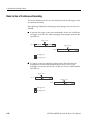
Basic Action of Continuous Recording . . . . . . . . . . . . . . . . . . . . . . . . . . . . . . . . . . .
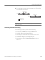
Performing Continuous Recording . . . . . . . . . . . . . . . . . . . . . . . . . . . . . . . . . . . . . .
3-57
3-58
3-59
MTX100A MPEG Recorder & Player User Manual
i
Table of Contents
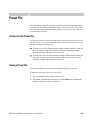
Preset File . . . . . . . . . . . . . . . . . . . . . . . . . . . . . . . . . . . . . . . . . . . . . . . . . . . 3-63
Contents of the Preset File . . . . . . . . . . . . . . . . . . . . . . . . . . . . . . . . . . . . . . . . . . . . . 3-63
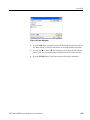
Saving a Preset File . . . . . . . . . . . . . . . . . . . . . . . . . . . . . . . . . . . . . . . . . . . . . . . . . . . 3-63
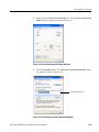
Loading a Preset File. . . . . . . . . . . . . . . . . . . . . . . . . . . . . . . . . . . . . . . . . . . . . . . . . . 3-64
Connecting to a Network . . . . . . . . . . . . . . . . . . . . . . . . . . . . . . . . . . . . . . 3-67
Connecting the MTX100A to your PC(s) . . . . . . . . . . . . . . . . . . . . . . . . . . . . . . . . . . 3-67
Setting Ethernet Network Parameters . . . . . . . . . . . . . . . . . . . . . . . . . . . . . . . . . . . . . 3-68
Outputting an ISDB-T Transport Stream . . . . . . . . . . . . . . . . . . . . . . . . . 3-73
Syntax . . . . . . . . . . . . . . . . . . . . . . . . . . . . . . . . . . . . . . . . . . . . . . . . . . . . 3-77
SCPI Commands and Queries . . . . . . . . . . . . . . . . . . . . . . . . . . . . . . . . . . . . . . . . . . 3-77
IEEE 488.2 Common Commands . . . . . . . . . . . . . . . . . . . . . . . . . . . . . . . . . . . . . . . 3-81
Remote Commands . . . . . . . . . . . . . . . . . . . . . . . . . . . . . . . . . . . . . . . . . . . 3-83
Common Commands. . . . . . . . . . . . . . . . . . . . . . . . . . . . . . . . . . . . . . . . . . . . . . . . . .
DISPLAY Commands . . . . . . . . . . . . . . . . . . . . . . . . . . . . . . . . . . . . . . . . . . . . . . . . .
MASS MEMORY Commands . . . . . . . . . . . . . . . . . . . . . . . . . . . . . . . . . . . . . . . . . .
PLAY Commands . . . . . . . . . . . . . . . . . . . . . . . . . . . . . . . . . . . . . . . . . . . . . . . . . . . .
RECORD Commands . . . . . . . . . . . . . . . . . . . . . . . . . . . . . . . . . . . . . . . . . . . . . . . .
SYSTEM Commands . . . . . . . . . . . . . . . . . . . . . . . . . . . . . . . . . . . . . . . . . . . . . . . .
Optional Commands . . . . . . . . . . . . . . . . . . . . . . . . . . . . . . . . . . . . . . . . . . . . . . . . .
3-84
3-86
3-86
3-88
3-100
3-104
3-107
Default Settings . . . . . . . . . . . . . . . . . . . . . . . . . . . . . . . . . . . . . . . . . . . . . 3-115
Error Message and Codes . . . . . . . . . . . . . . . . . . . . . . . . . . . . . . . . . . . . 3-119
Command Errors . . . . . . . . . . . . . . . . . . . . . . . . . . . . . . . . . . . . . . . . . . . . . . . . . . . .
Execution Errors . . . . . . . . . . . . . . . . . . . . . . . . . . . . . . . . . . . . . . . . . . . . . . . . . . . .
Device Specific Errors . . . . . . . . . . . . . . . . . . . . . . . . . . . . . . . . . . . . . . . . . . . . . . .
Query Errors . . . . . . . . . . . . . . . . . . . . . . . . . . . . . . . . . . . . . . . . . . . . . . . . . . . . . . .
3-119
3-120
3-122
3-122
Network Interface Specifications . . . . . . . . . . . . . . . . . . . . . . . . . . . . . . . 3-123
Checking Remote Command Operation . . . . . . . . . . . . . . . . . . . . . . . . . . . . . . . . . . 3-123
Using the IEEE1394 Interface (Option 05 Only) . . . . . . . . . . . . . . . . . . 3-125
Note for Connections . . . . . . . . . . . . . . . . . . . . . . . . . . . . . . . . . . . . . . . . . . . . . . . .
Point-to-Point Connection . . . . . . . . . . . . . . . . . . . . . . . . . . . . . . . . . . . . . . . . . . . .
Data Probing . . . . . . . . . . . . . . . . . . . . . . . . . . . . . . . . . . . . . . . . . . . . . . . . . . . . . . .
ASI/IEEE1394 Conversion . . . . . . . . . . . . . . . . . . . . . . . . . . . . . . . . . . . . . . . . . . .
About the Partial Transport Stream. . . . . . . . . . . . . . . . . . . . . . . . . . . . . . . . . . . . . .
3-125
3-126
3-128
3-129
3-131
Appendix A: Specifications . . . . . . . . . . . . . . . . . . . . . . . . . . . . . . . . . . . .
A-1
Appendices
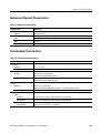
Performance Conditions . . . . . . . . . . . . . . . . . . . . . . . . . . . . . . . . . . . . . . . . . . . . . . . A-1
Functional Specifications . . . . . . . . . . . . . . . . . . . . . . . . . . . . . . . . . . . . . . . . . . . . . . A-1
Electrical Specifications . . . . . . . . . . . . . . . . . . . . . . . . . . . . . . . . . . . . . . . . . . . . . . . A-2
Mechanical (Physical) Characteristics . . . . . . . . . . . . . . . . . . . . . . . . . . . . . . . . . . . A-11
Environmental Characteristics . . . . . . . . . . . . . . . . . . . . . . . . . . . . . . . . . . . . . . . . . A-11
Certifications and Compliances . . . . . . . . . . . . . . . . . . . . . . . . . . . . . . . . . . . . . . . . A-12
ii
MTX100A MPEG Recorder & Player User Manual
Table of Contents
Appendix B: Using the ReMux Application . . . . . . . . . . . . . . . . . . . . . . . . B-1
Starting and Exiting ReMux . . . . . . . . . . . . . . . . . . . . . . . . . . . . . . . . . . . . . . . . . . . .
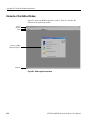
Elements of the ReMux Window . . . . . . . . . . . . . . . . . . . . . . . . . . . . . . . . . . . . . . . . .
Using the ReMux Menus . . . . . . . . . . . . . . . . . . . . . . . . . . . . . . . . . . . . . . . . . . . . . . .
ReMux Tutorials . . . . . . . . . . . . . . . . . . . . . . . . . . . . . . . . . . . . . . . . . . . . . . . . . . . . .
B-1
B-2
B-5
B-8
Appendix C: Using the Scheduler Application (Option SC Only) . . . . . . C-1
Starting and Exiting Scheduler . . . . . . . . . . . . . . . . . . . . . . . . . . . . . . . . . . . . . . . . . .
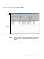
Elements of the Scheduler Application Window . . . . . . . . . . . . . . . . . . . . . . . . . . . . .
Using the Scheduler Menus . . . . . . . . . . . . . . . . . . . . . . . . . . . . . . . . . . . . . . . . . . . . .
Status/Control Panel. . . . . . . . . . . . . . . . . . . . . . . . . . . . . . . . . . . . . . . . . . . . . . . . . .
Scheduler Tutorials . . . . . . . . . . . . . . . . . . . . . . . . . . . . . . . . . . . . . . . . . . . . . . . . . .
Installing Scheduler on a PC . . . . . . . . . . . . . . . . . . . . . . . . . . . . . . . . . . . . . . . . . . .
Starting and Exiting Scheduler on Your PC. . . . . . . . . . . . . . . . . . . . . . . . . . . . . . . .
C-1
C-2
C-5
C-15
C-18
C-23
C-25
Appendix D: Control Signal for Option 02 . . . . . . . . . . . . . . . . . . . . . . . . D-1
Appendix E: Defragment the Hard Disk Drive . . . . . . . . . . . . . . . . . . . . . E-1
Appendix F: Using the Recovery Discs . . . . . . . . . . . . . . . . . . . . . . . . . . . . F-1
Reinstalling Windows XP . . . . . . . . . . . . . . . . . . . . . . . . . . . . . . . . . . . . . . . . . . . . . .
Reinstalling the MTX100A Application . . . . . . . . . . . . . . . . . . . . . . . . . . . . . . . . . . .
Restoring the IEEE1394b Port Speed Setting . . . . . . . . . . . . . . . . . . . . . . . . . . . . . . .
Appendix G: Inspection and Cleaning . . . . . . . . . . . . . . . . . . . . . . . . . . .
F-1
F-2
F-3
G-1
Exterior Inspection. . . . . . . . . . . . . . . . . . . . . . . . . . . . . . . . . . . . . . . . . . . . . . . . . . . . G-1
Exterior Cleaning . . . . . . . . . . . . . . . . . . . . . . . . . . . . . . . . . . . . . . . . . . . . . . . . . . . . . G-1
Glossary
Index
MTX100A MPEG Recorder & Player User Manual
iii
List of Figures
List of Figures
iv
Figure 1-1: Rear-panel power connector . . . . . . . . . . . . . . . . . . . . . . . . . .
Figure 1-2: Front-panel ON/STBY switch . . . . . . . . . . . . . . . . . . . . . . . . .
Figure 1-3: Windows Security Alert dialog box . . . . . . . . . . . . . . . . . . . . .
Figure 1-4: Select File dialog box . . . . . . . . . . . . . . . . . . . . . . . . . . . . . . . .
Figure 1-5: Equipment connection for the functional check . . . . . . . . . .
1-7
1-8
1-8
1-10
1-11
Figure 2-1: MTX100A front panel . . . . . . . . . . . . . . . . . . . . . . . . . . . . . . .
Figure 2-2: MTX100A rear panel . . . . . . . . . . . . . . . . . . . . . . . . . . . . . . . .
Figure 2-3: Elements of the Play screen . . . . . . . . . . . . . . . . . . . . . . . . . . .
Figure 2-4: Play status indicator . . . . . . . . . . . . . . . . . . . . . . . . . . . . . . . . .
Figure 2-5: Status bar . . . . . . . . . . . . . . . . . . . . . . . . . . . . . . . . . . . . . . . . . .
Figure 2-6: ASI interface . . . . . . . . . . . . . . . . . . . . . . . . . . . . . . . . . . . . . .
Figure 2-7: Universal parallel/serial interface . . . . . . . . . . . . . . . . . . . . .
Figure 2-8: IEEE1394/ASI interface . . . . . . . . . . . . . . . . . . . . . . . . . . . . .
Figure 2-9: SMPTE310M/ASI/SPI interface . . . . . . . . . . . . . . . . . . . . . .
Figure 2-10: Front panel showing the menu controls . . . . . . . . . . . . . . .
Figure 2-11: Display status of the menu commands . . . . . . . . . . . . . . . .
Figure 2-12: Keypad . . . . . . . . . . . . . . . . . . . . . . . . . . . . . . . . . . . . . . . . . .
Figure 2-13: Select File dialog box . . . . . . . . . . . . . . . . . . . . . . . . . . . . . . .
Figure 2-14: Hierarchy view of the transport stream file . . . . . . . . . . . .
Figure 2-15: Play status indicator . . . . . . . . . . . . . . . . . . . . . . . . . . . . . . .
Figure 2-16: Transport stream display from an MPEG test system . . .
Figure 2-17: No Signal message . . . . . . . . . . . . . . . . . . . . . . . . . . . . . . . . .
Figure 2-18: Record status indicator . . . . . . . . . . . . . . . . . . . . . . . . . . . . .
2-2
2-4
2-6
2-7
2-9
2-11
2-12
2-13
2-13
2-14
2-15
2-16
2-20
2-21
2-21
2-22
2-22
2-23
Figure 3-1: Select File dialog box . . . . . . . . . . . . . . . . . . . . . . . . . . . . . . . . .
Figure 3-2: Clock dialog box . . . . . . . . . . . . . . . . . . . . . . . . . . . . . . . . . . . .
Figure 3-3: Set Non-TS Sync dialog box . . . . . . . . . . . . . . . . . . . . . . . . . . .
Figure 3-4: PCR Initial Value dialog box . . . . . . . . . . . . . . . . . . . . . . . . .
Figure 3-5: Start/Stop Position dialog box . . . . . . . . . . . . . . . . . . . . . . . .
Figure 3-6: Timer Play/Record dialog box . . . . . . . . . . . . . . . . . . . . . . . .
Figure 3-7: Others dialog box . . . . . . . . . . . . . . . . . . . . . . . . . . . . . . . . . .
Figure 3-8: IEEE1394 dialog box (Play screen) . . . . . . . . . . . . . . . . . . . .
Figure 3-9: Communication dialog box . . . . . . . . . . . . . . . . . . . . . . . . . .
Figure 3-10: Option Key dialog box . . . . . . . . . . . . . . . . . . . . . . . . . . . . .
3-4
3-7
3-9
3-10
3-11
3-13
3-14
3-21
3-23
3-24
MTX100A MPEG Recorder & Player User Manual
List of Figures
Figure 3-11: Status dialog box . . . . . . . . . . . . . . . . . . . . . . . . . . . . . . . . . .
Figure 3-12: Target dialog box . . . . . . . . . . . . . . . . . . . . . . . . . . . . . . . . .
Figure 3-13: Others dialog box . . . . . . . . . . . . . . . . . . . . . . . . . . . . . . . . .
Figure 3-14: IEEE1394 dialog box (Record screen) . . . . . . . . . . . . . . . .
Figure 3-15: Example of the hierarchy display . . . . . . . . . . . . . . . . . . . .
Figure 3-16: PCR Inaccuracy dialog box . . . . . . . . . . . . . . . . . . . . . . . . .
Figure 3-17: PCR Inaccuracy dialog box . . . . . . . . . . . . . . . . . . . . . . . . .
Figure 3-18: Jitter function with a sine jitter pattern applied . . . . . . . .
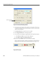
Figure 3-19: Continuous Recording check box . . . . . . . . . . . . . . . . . . . .
Figure 3-20: File counter . . . . . . . . . . . . . . . . . . . . . . . . . . . . . . . . . . . . . .
Figure 3-21: Save As dialog box . . . . . . . . . . . . . . . . . . . . . . . . . . . . . . . .
Figure 3-22: Open dialog box . . . . . . . . . . . . . . . . . . . . . . . . . . . . . . . . . .
Figure 3-23: Pin connections for a crossover Ethernet cable . . . . . . . . .
Figure 3-24: Network Connections window . . . . . . . . . . . . . . . . . . . . . . .
Figure 3-25: Local Area Connection Status dialog box . . . . . . . . . . . . .
Figure 3-26: Local Area Connection Properties dialog box . . . . . . . . . .
Figure 3-27: Internet Protocol (TCP/IP) Properties dialog box . . . . . .
Figure 3-28: Hierarchy view of the ISDB-T transport stream file . . . .
Figure 3-29: ISDB-T Information dialog box . . . . . . . . . . . . . . . . . . . . .
Figure 3-30: Example of SCPI subsystem hierarchy tree . . . . . . . . . . . .
Figure 3-31: Example of abbreviating a command . . . . . . . . . . . . . . . . .
Figure 3-32: Example of chaining commands and queries . . . . . . . . . . .
Figure 3-33: Example of omitting root and lower-level nodes
in a chained message . . . . . . . . . . . . . . . . . . . . . . . . . . . . . . . . . . . . . . .
Figure 3-34: Run dialog box . . . . . . . . . . . . . . . . . . . . . . . . . . . . . . . . . .
Figure 3-35: Telnet window . . . . . . . . . . . . . . . . . . . . . . . . . . . . . . . . . . .
Figure 3-36: Connection example for point-to-point connection . . . . .
Figure 3-37: Connection example for data probing . . . . . . . . . . . . . . .
Figure 3-38: Connection example for ASI → IEEE1394 conversion . .
Figure 3-39: Connection example for IEEE1394 → ASI conversion . .
Figure 3-40: Partial transport stream . . . . . . . . . . . . . . . . . . . . . . . . . .
3-25
3-27
3-29
3-32
3-37
3-47
3-53
3-55
3-60
3-60
3-64
3-65
3-67
3-68
3-69
3-69
3-70
3-74
3-75
3-77
3-79
3-79
3-80
3-124
3-124
3-126
3-128
3-129
3-130
3-131
Figure A-1: Timing diagram of the SPI and universal
parallel/serial interfaces . . . . . . . . . . . . . . . . . . . . . . . . . . . . . . . . . . . . . A-10
Figure B-1: ReMux application window . . . . . . . . . . . . . . . . . . . . . . . . . . B-2
Figure B-2: Select Remux Mode dialog box . . . . . . . . . . . . . . . . . . . . . . . . B-5
Figure B-3: OPTION dialog box . . . . . . . . . . . . . . . . . . . . . . . . . . . . . . . . . B-7
MTX100A MPEG Recorder & Player User Manual
v
List of Figures
vi
Figure B-4: Editing window for the Make S-TMCC TS mode . . . . . . . .
Figure B-5: Edit TS Information dialog box . . . . . . . . . . . . . . . . . . . . .
Figure B-6: Windows displaying a transport stream icon . . . . . . . . . .
Figure B-7: Edit TMCC Information dialog box (S-TMCC) . . . . . . . .
Figure B-8: Editing window for the ReMux to M-TMCC TS from
S-TMCC TS mode . . . . . . . . . . . . . . . . . . . . . . . . . . . . . . . . . . . . . . . . .
Figure B-9: Transport stream is multiplexed . . . . . . . . . . . . . . . . . . . . .
Figure B-10: Edit TMCC Information dialog box (M-TMCC) . . . . . .
Figure B-11: Add TMCC dialog box . . . . . . . . . . . . . . . . . . . . . . . . . . . .
Figure B-12: Editing window for the ReMux to M-TMCC TS mode .
Figure B-13: Editing window for the DeMux M-TMCC TS mode . . .
Figure B-14: DEMUX dialog box . . . . . . . . . . . . . . . . . . . . . . . . . . . . . .
B-9
B-10
B-11
B-12
B-13
B-14
B-15
B-16
B-18
B-20
B-21
Figure C-1: Scheduler application window (schedule play mode) . . . . .
Figure C-2: MTX/RTX Host Name dialog box . . . . . . . . . . . . . . . . . . . .
Figure C-3: Scheduler Settings dialog box . . . . . . . . . . . . . . . . . . . . . . . .
Figure C-4: Play Properties dialog box . . . . . . . . . . . . . . . . . . . . . . . . . .
Figure C-5: Save as dialog box . . . . . . . . . . . . . . . . . . . . . . . . . . . . . . . . .
Figure C-6: Record Properties dialog box . . . . . . . . . . . . . . . . . . . . . . .
Figure C-7: Status/control panel (schedule play mode) . . . . . . . . . . . .
Figure C-8: Schedule Property dialog box . . . . . . . . . . . . . . . . . . . . . . .
C-2
C-6
C-7
C-10
C-13
C-14
C-15
C-16
Figure D-1: Timing relationship of the signals on the Universal In/Out
connector . . . . . . . . . . . . . . . . . . . . . . . . . . . . . . . . . . . . . . . . . . . . . . . . .
D-2
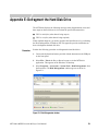
Figure E-1: Disk Defragmenter window . . . . . . . . . . . . . . . . . . . . . . . . . .
Figure E-2: Defragmentation Complete dialog box . . . . . . . . . . . . . . . . .
E-1
E-2
MTX100A MPEG Recorder & Player User Manual
List of Tables
List of Tables
Table 1-1: Power cord identification . . . . . . . . . . . . . . . . . . . . . . . . . . . . .
Table 1-2: Environmental operating requirements . . . . . . . . . . . . . . . . . .
Table 1-3: AC line power requirement . . . . . . . . . . . . . . . . . . . . . . . . . . . .
1-3
1-6
1-6
Table 2-1: Tutorial recommended test equipment and accessories . . . .
2-19
Table 3-1: File menu commands (Play screen) . . . . . . . . . . . . . . . . . . . . . 3-3
Table 3-2: View menu commands . . . . . . . . . . . . . . . . . . . . . . . . . . . . . . . . 3-5
Table 3-3: Play menu commands . . . . . . . . . . . . . . . . . . . . . . . . . . . . . . . . 3-5
Table 3-4: ASI I/F menu commands (Play screen) . . . . . . . . . . . . . . . . . 3-19
Table 3-5: Univ I/F menu commands (Play screen) . . . . . . . . . . . . . . . . 3-20
Table 3-6: ASI/1394 menu commands (Play screen) . . . . . . . . . . . . . . . . 3-20
Table 3-7: 310M/ASI/SPI menu commands (Play screen) . . . . . . . . . . . 3-22
Table 3-8: Utility menu commands . . . . . . . . . . . . . . . . . . . . . . . . . . . . . . 3-22
Table 3-9: File menu commands (Record screen) . . . . . . . . . . . . . . . . . . 3-26
Table 3-10: Record menu commands . . . . . . . . . . . . . . . . . . . . . . . . . . . . 3-27
Table 3-11: ASI I/F menu command (Record screen) . . . . . . . . . . . . . . 3-30
Table 3-12: Univ I/F menu commands (Record screen) . . . . . . . . . . . . . 3-30
Table 3-13: ASI/1394 menu commands (Record screen) . . . . . . . . . . . . 3-31
Table 3-14: 310M/ASI/SPI menu command (Record screen) . . . . . . . . 3-33
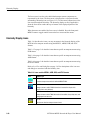
Table 3-15: Toolbar button descriptions . . . . . . . . . . . . . . . . . . . . . . . . . 3-34
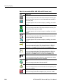
Table 3-16: Icons used for MPEG-2, ARIB, DVB, and ATSC formats
3-38
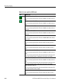
Table 3-17: Icons specific to DVB format . . . . . . . . . . . . . . . . . . . . . . . . 3-41
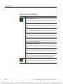
Table 3-18: Icons specific to ARIB format . . . . . . . . . . . . . . . . . . . . . . . . 3-42
Table 3-19: Icons specific to ATSC format . . . . . . . . . . . . . . . . . . . . . . . 3-44
Table 3-20: PCR Inaccuracy dialog box parameters . . . . . . . . . . . . . . . 3-48
Table 3-21: Parameter types used in syntax descriptions . . . . . . . . . . . . 3-78
Table 3-22: BNF symbols and meanings . . . . . . . . . . . . . . . . . . . . . . . . . 3-81
Table 3-23: Default Settings . . . . . . . . . . . . . . . . . . . . . . . . . . . . . . . . . . 3-115
Table 3-24: Command errors . . . . . . . . . . . . . . . . . . . . . . . . . . . . . . . . . 3-119
Table 3-25: Execution errors . . . . . . . . . . . . . . . . . . . . . . . . . . . . . . . . . . 3-120
Table 3-26: Device specific errors . . . . . . . . . . . . . . . . . . . . . . . . . . . . . . 3-122
Table 3-27: Query errors . . . . . . . . . . . . . . . . . . . . . . . . . . . . . . . . . . . . . 3-122
Table A-1: Functional specifications . . . . . . . . . . . . . . . . . . . . . . . . . . . . . A-1
MTX100A MPEG Recorder & Player User Manual
vii
List of Tables
Table A-2: Mainframe . . . . . . . . . . . . . . . . . . . . . . . . . . . . . . . . . . . . . . . . A-2
Table A-3: ASI interface (Option 01) . . . . . . . . . . . . . . . . . . . . . . . . . . . . A-5
Table A-4: Universal parallel/serial interface (Option 02) . . . . . . . . . . . A-6
Table A-5: IEEE1394/ASI interface (Option 05) . . . . . . . . . . . . . . . . . . . A-8
Table A-6: SMPTE310M/ASI/SPI interface (Option 07) . . . . . . . . . . . . A-8
Table A-7: Mechanical characteristics . . . . . . . . . . . . . . . . . . . . . . . . . . A-11
Table A-8: Environmental characteristics . . . . . . . . . . . . . . . . . . . . . . . A-11
Table A-9: Certifications and compliances . . . . . . . . . . . . . . . . . . . . . . . A-12
viii
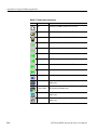
Table B-1: Element of the ReMux window . . . . . . . . . . . . . . . . . . . . . . . .
Table B-2: Toolbar button descriptions . . . . . . . . . . . . . . . . . . . . . . . . . .
Table B-3: ReMux File menu commands . . . . . . . . . . . . . . . . . . . . . . . . .
Table B-4: ReMux File menu commands . . . . . . . . . . . . . . . . . . . . . . . . .
Table B-5: ReMux menu commands . . . . . . . . . . . . . . . . . . . . . . . . . . . . .
Table B-6: ReMux Window menu commands . . . . . . . . . . . . . . . . . . . . .
Table B-7: ReMux View menu commands . . . . . . . . . . . . . . . . . . . . . . . .
B-3
B-4
B-5
B-6
B-6
B-7
B-8
Table C-1: Toolbar button descriptions . . . . . . . . . . . . . . . . . . . . . . . . . .
Table C-2: File menu commands . . . . . . . . . . . . . . . . . . . . . . . . . . . . . . . .
Table C-3: View menu commands . . . . . . . . . . . . . . . . . . . . . . . . . . . . . . .
Table C-4: Schedule menu commands . . . . . . . . . . . . . . . . . . . . . . . . . . .
Table C-5: Stream menu commands . . . . . . . . . . . . . . . . . . . . . . . . . . . . .
C-3
C-5
C-5
C-6
C-9
Table D-1: Pin assignment of the Universal In/Out connector . . . . . . . .
D-1
MTX100A MPEG Recorder & Player User Manual
General Safety Summary
Review the following safety precautions to avoid injury and prevent damage to this
product or any products connected to it. To avoid potential hazards, use this
product only as specified.
Only qualified personnel should perform service procedures.
To Avoid Fire or
Personal Injury
Use Proper Power Cord. Use only the power cord specified for this product and
certified for the country of use.
Ground the Product. This product is grounded through the grounding conductor of
the power cord. To avoid electric shock, the grounding conductor must be
connected to earth ground. Before making connections to the input or output
terminals of the product, ensure that the product is properly grounded.
Observe All Terminal Ratings. To avoid fire or shock hazard, observe all ratings
and markings on the product. Consult the product manual for further ratings
information before making connections to the product.
Do Not Operate Without Covers. Do not operate this product with covers or panels
removed.
Use Proper Fuse. Use only the fuse type and rating specified for this product.
Avoid Exposed Circuitry. Do not touch exposed connections and components when
power is present.
Do Not Operate With Suspected Failures. If you suspect there is damage to this
product, have it inspected by qualified service personnel.
Do Not Operate in Wet/Damp Conditions.
Do Not Operate in an Explosive Atmosphere.
Keep Product Surfaces Clean and Dry.
Provide Proper Ventilation. Refer to the manual’s installation instructions for
details on installing the product so it has proper ventilation.
No Power Switch. The power supply cord is considered the disconnecting device,
disconnect the main power by means of the power cord.
MTX100A MPEG Recorder & Player User Manual
Test Equipment Depot - 800.517.8431 - 99 Washington Street Melrose, MA 02176
FAX 781.665.0780 - TestEquipmentDepot.com
ix
General Safety Summary
Symbols and Terms
Terms in this Manual. These terms may appear in this manual:
WARNING. Warning statements identify conditions or practices that could result in
injury or loss of life.
CAUTION. Caution statements identify conditions or practices that could result in
damage to this product or other property.
Terms on the Product. These terms may appear on the product:
DANGER indicates an injury hazard immediately accessible as you read the
marking.
WARNING indicates an injury hazard not immediately accessible as you read the
marking.
CAUTION indicates a hazard to property including the product.
Symbols on the Product. The following symbols may appear on the product:
CAUTION
Refer to Manual
x
Protective Ground
(Earth) Terminal
MTX100A MPEG Recorder & Player User Manual
Environmental Considerations
This section provides information about the environmental impact of the product.
Product End-of-Life
Handling
Observe the following guidelines when recycling an instrument or component:
Equipment Recycling. Production of this equipment required the extraction and use
of natural resources. The equipment may contain substances that could be harmful
to the environment or human health if improperly handled at the product's end of
life. In order to avoid release of such substances into the environment and to reduce
the use of natural resources, we encourage you to recycle this product in an
appropriate system that will ensure that most of the materials are reused or recycled
appropriately.
The symbol shown to the left indicates that this product
complies with the European Union's requirements according to
Directive 2002/96/EC on waste electrical and electronic
equipment (WEEE). For information about recycling options,
check the Support/Service section of the Tektronix Web site
(www.tektronix.com).
Mercury Notification. This product uses an LCD backlight lamp that contains
mercury. Disposal may be regulated due to environmental considerations. Please
contact your local authorities or, within the United States, the Electronics
Industries Alliance (www.eiae.org) for disposal or recycling information.
Restriction of Hazardous
Substances
This product has been classified as Monitoring and Control equipment, and is
outside the scope of the 2002/95/EC RoHS Directive. This product is known to
contain lead, cadmium, mercury, and hexavalent chromium.
MTX100A MPEG Recorder & Player User Manual
xi
Environmental Considerations
xii
MTX100A MPEG Recorder & Player User Manual
Preface
The user manual for the MTX100A MPEG Recorder & Player contains the
following sections:
Getting Started briefly describes the MTX100A MPEG Recorder & Player and
provides installation instructions, option and accessory lists, repacking
instructions, and power on and off instructions.
Operating Basics provides an overview of the front panel controls and rear panel
connections, operating principles, basic operating procedures, and numeric input
methods. This section also provides examples of basic data outputting and
recording.
Reference provides detailed information about the functions and use of the
MTX100A MPEG Recorder & Player’s main menus, and presents descriptions of
all programming commands and the syntax used in command descriptions. This
section also provides instructions for setting the network parameters for the
Ethernet port.
Appendices provides product specifications, instructions for operating the ReMux
and Scheduler applications, defragging the hard disk, recovering the system, and
inspecting and cleaning the MTX100A MPEG Recorder & Player.
Terms
This manual uses the following terms:
Stream: Generic term for transport streams and data streams of Non TS format
(data format other than transport stream format).
S-TMCC (Single TMCC): Transport stream to which TMCC (Transmission
and Multiplexing Configuration Control) information is inserted into the
8 bytes in its Reed-Solomon code area (16 bytes). It is defined in the ISDB-S
(Integrated Services Digital Broadcasting-Satellite) system.
M-TMCC (Multi TMCC): Transport stream to which TMCC information is
inserted into the sync byte area, and having super frame structure. It is defined
in the ISDB-S system.
MTX100A MPEG Recorder & Player User Manual
xiii
Preface
Related Manual
The following related documentation for the instrument is available:
The MTX100A MPEG Recorder & Player Service Manual (Tektronix part
number 071-1754-XX) describes how to maintain and service the MTX100A
and provides a complete module-level description of the operation of the
instrument. This manual is an optional accessory.
xiv
MTX100A MPEG Recorder & Player User Manual
Getting Started
Getting Started
This section provides the following information:
Product description
List of standard and optional accessories
List of instrument options
Initial product inspection procedure
Installation instructions
Instructions for repackaging the instrument for shipment
Functional check procedure
Windows operations
Product Description
The MTX100A MPEG Recorder & Player records and plays MPEG-2 transport
streams that are compliant with ATSC, DVB, and ARIB standards.
The MTX100A provides the following features:
Data rate: 214 Mbps maximum; 256 Kbps minimum
Hierarchy display of stored or captured transport stream
188, 204, 208 bytes packet size, S-TMCC, M-TMCC, non transport stream,
and partial transport stream output formats
Real-time updating of stream parameters; continuity_counter, PCR/PTS/DTS,
TOT/TDT/STT, NPT, and Reed Solomon (ISDB-T only)
Continuous recording of captured streams
PCR jitter insertion
Triggered stream capture
Full remote control using Ethernet interface
Scheduler application for automated stream playout and record (Option SC
only)
MTX100A MPEG Recorder & Player User Manual
1-1
Getting Started
Optional ASI, universal parallel/serial, IEEE1394/ASI, and
SMPTE310M/ASI/SPI interfaces available
The MTX100A includes the ReMux application software that provides the
capability to create a transport stream of super frame structure defined in the
ISDB-S systems from an MPEG2 transport stream. Refer to Appendix B: Using
ReMux Application for detailed information about the ReMux application.
NOTE. When inputting/outputting a stream for a long time, the stream may be
intermittent because of a processing condition of the hard disk or the system
process of Windows XP.
Standard Accessories
The following accessories are shipped with the MTX100A:
Document, CD-ROMs, and
Other Parts
The following document, CD-ROMs, and other parts are standard accessories:
MTX100A MPEG Recorder & Player User Manual.
English (Option L0): Tektronix part number 071-1731-XX.
Japanese (Option L5): Tektronix part number 071-1753-XX.
Windows XP Professional recovery DVD-ROM, Tektronix part number
063-3864-XX.
Sample Stream CD-ROM, Tektronix part number 063-3865-XX.
Application Software Recovery CD-ROM, Tektronix part number
063-3866-XX.
Interface cable (D-sub 25-pin, twisted pair), Tektronix part number
012-A220-00.
USB keyboard, Tektronix part number 119-B146-00.
USB mouse, Tektronix part number 119-B145-00.
Front cover, Tektronix part number 200-3897-00.
1-2
MTX100A MPEG Recorder & Player User Manual
Getting Started
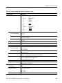
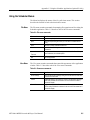
Power Cords
All MTX100A MPEG Recorder & Players are shipped with one of the following
power cord options. Power codes for use in North America are UL listed and CSA
certified. Cords for use in areas other than North America are approved by at least
one authority acceptable in the country to which the product is shipped.
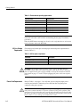
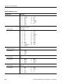
Table 1-1: Power cord identification
Plug configuration
Normal usage
North America
115 V
Option number
Standard (A0)
Universal Euro
220 V
A1
United Kingdom
240 V
A2
Australia
240 V
A3
North America
250 V
A4
Switzerland
240V
A5
Japan
100 V
A6
China
240 V
A10
No power code supplied.
A99
MTX100A MPEG Recorder & Player User Manual
Test Equipment Depot - 800.517.8431 - 99 Washington Street Melrose, MA 02176
FAX 781.665.0780 - TestEquipmentDepot.com
1-3
Getting Started
Optional Accessories
The following items are optional accessories:
MTX100A MPEG Recorder & Player Service Manual, Tektronix part number
071-1754-XX.
WFM7F05 rackmount kit
1700F06 blank panel
Options
The MTX100A can be ordered with the following options:
Instrument Options
The following instrument options are available for the MTX100A:
Option 01: Adds the ASI interface.
Option 02: Adds the Universal Parallel/Serial interface.
Option 05: Adds the IEEE1394/ASI interface.
Option 07: Adds the SMPTE310M/ASI/SPI interface.
Option SC: Adds the Scheduler software.
Power Cord Options
1-4
See Table 1-1 on page 1-3.
MTX100A MPEG Recorder & Player User Manual
Getting Started
Initial Product Inspection
Perform the following product inspection procedure when you receive your
instrument:
1. Inspect the shipping carton for external damage, which indicates possible
damage to the instrument.
2. Remove the MTX100A from the shipping carton.
3.
Check that the instrument has not been damaged in transit. The exterior should
not have any scratches or impact marks. Prior to shipment the instrument is
thoroughly inspected for mechanical defects.
NOTE. Save the shipping carton and packaging materials for instrument
repackaging in case shipment becomes necessary.
4. Verify that the shipping carton contains the instrument, the standard
accessories, and any optional accessories that you ordered.
5. Perform the functional check procedure (refer to Functional Check Procedure
on page 1-10) after installing the instrument.
Installation
Before you install the instrument, refer to the General Safety Summary section at
the front of this manual for power source, grounding, and other safety information.
Environment Operating
Requirements
Verify that the location of your installation has the proper operating environment.
CAUTION. Damage to the instrument can occur if this instrument is powered on at
temperatures outside of the specified temperature range.
MTX100A MPEG Recorder & Player User Manual
1-5
Getting Started
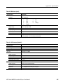
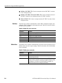
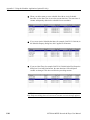
Table 1-2: Environmental operating requirements
Characteristics
MTX100A ambient temperatures
MTX100A relative humidity
Clearance on top
Clearance on left side
Clearance on right side
Clearance in rear (from the fan guard)
Specifications
from +5 °C to + 40 °C
from 20% to 80%
5.0 cm (2 in)
5.0 cm (2 in)
5.0 cm (2 in)
5.0 cm (2 in)
NOTE. If you are installing the instrument in a dedicated rack, refer to the
instruction sheet that comes with the rackmounting kit for proper installation
procedures.
When the MTX100A is mounted in a 19-inch rack, verify that there is at least one
unit of clearance above the MTX100A.
AC Line Voltage
Requirement
Check that your location provides the proper electrical power requirements as
listed in Table 1-3.
Table 1-3: AC line power requirement
Parameter
Line voltage range
Line frequency
Maximum power
Description
100 to 240 V
50/60 Hz
180 VA
CAUTION. The instrument does not have a power switch, but does have an
on/standby switch. When you connect the power cable to the AC line connector,
power is applied to the power supply standby circuit of the instrument. Read all
instructions on pages 1-7 and 1-8 before plugging the power cable into a power
source.
Power Cord Requirement
Refer to Table 1-1 on page 1-3 to verify that you are using the proper power
cord for your location. Connect the power cord from the rear-panel power
connector to the power system.
CAUTION. The instrument is shipped with a power cord appropriate for use with
your power systems (normal 115 V power system or 230 V power system). If the
instrument is to be used with a power system other than that specified in the order,
the power cord must be replaced with one appropriate for the power source used.
Refer to Table 1-1 for a listing of available power cords.
1-6
MTX100A MPEG Recorder & Player User Manual
Getting Started
Applying Power to the
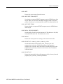
Instrument
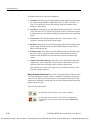
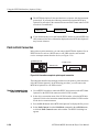
After you have verified the operating environment, AC line, and power cord
requirements, plug the power cord into the power connector on the rear panel (see
Figure 1-1), and then plug the power cord into the local power source.
Clock/Ref
In
SPI
In/Out
Trig
In/Out
IEEE 1394b
Printer
VGA
LAN
Com
Power connector
Figure 1-1: Rear-panel power connector
NOTE. To make a selection in a Windows dialog box after you power on the
instrument, connect a mouse to the USB connector on the front panel before you
power on.
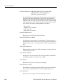
Power On. Press the ON/STBY switch (see Figure 1-2) to power on the instrument.
After you power on the instrument, verify that the fan on the rear panel is operating.
To verify that the fan is operating, place your hand behind the right side of the
instrument. You should be able to feel the fan's air flow.
CAUTION. Do not operate the instrument if the cooling fan does not operate when
you turn the instrument on. Serious damage to your instrument can occur from
overheating if the cooling fan is not operating.
MTX100A MPEG Recorder & Player User Manual
1-7
Getting Started
M T X 100 A M PE G R ecorder & Player
ON/STBY switch
Figure 1-2: Front-panel ON/STBY switch
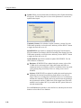
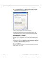
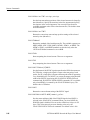
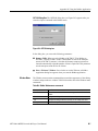
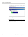
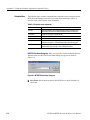
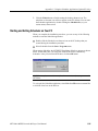
The first time you power on the instrument, the Windows Security Alert dialog
box appears as shown in Figure 1-3. This dialog box appears when a program tries
to use the resources or the ports on the system that are covered by the firewall.
Figure 1-3: Windows Security Alert dialog box
Click the Unblock button so that Windows allows the program (MPEG Series
Application) to run.
When you click the Unblock button, the MTX100A application window (Play
screen) is displayed.
1-8
MTX100A MPEG Recorder & Player User Manual
Getting Started
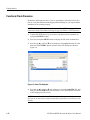
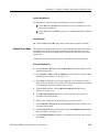
Functional Check Procedure
Perform the following procedure if you are operating the instrument for the first
time (to verify that the instrument shipped without damage) or you suspect that the
instrument is not working properly:
NOTE. Before you perform this procedure, install the MTX100A using the
instructions listed in Installation starting on page Up Windows XP Professional.
1. Connect the MTX100A to a power source, and then turn the instrument on
using the ON/STBY switch.
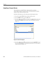
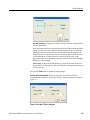
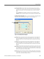
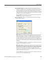
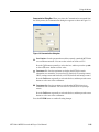
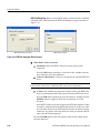
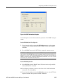
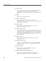
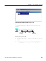
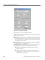
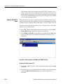
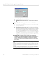
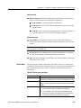
2. Press the front-panel MENU button to display the File menu command list.
3. Press the up (S) or down (T) arrow button to select Open from the list, and
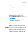
then press the ENTER button to open the Select File dialog box shown in
Figure 1-4.
Figure 1-4: Select File dialog box
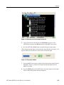
4. Press the up (S) or down (T) arrow button to select the test64.TRP file, and
then press the ENTER button. The hierarchy view of the transport stream file
will be displayed on the screen.
NOTE. You can select the test40.TRP file in step 4 of this procedure if you need to
decrease the bit rate of the transport stream due to performance restrictions in your
decoder.
1-10
MTX100A MPEG Recorder & Player User Manual
Getting Started
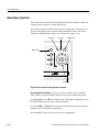
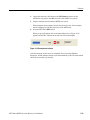
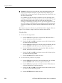
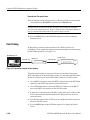
5. Connect the interface cable provided with the instrument between the SPI
IN/OUT connector on the MTX100A rear panel and the SPI IN connector on
an MPEG decoder. See Figure 1-5.
6. Connect the decoder to a picture monitor.
7. Press the MTX100A PLAY button to start the transport stream output. When
transport stream output is started, the Play Status indicator appears on the
screen.
8. Check that the picture from the transport stream is displayed correctly on the
picture monitor.
MTX100A rear panel
Interface cable
MPEG decoder
SPI in
Output
Picture monitor
Input
Figure 1-5: Equipment connection for the functional check
MTX100A MPEG Recorder & Player User Manual
1-11
Getting Started
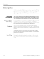
Windows Operations
All of the functions of the MTX100A are performed as an application (MTX100A
application) on the Windows XP operating system. Therefore, if you connect the
keyboard and mouse provided with the instrument to the front-panel USB
connectors, you can operate the MTX100A system with the same environment as
a Windows PC.
Operation on the
Play/Record Screen
When you have connected a keyboard and mouse to the instrument, you can use
them to make menu selections and parameter settings in the Play/Record screen.
These operations behave in the same manner as the other Windows applications.
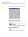
Displaying the Windows
Screen (Desktop)
To display the Windows screen (Desktop), select Minimize or Exit from the File
menu in the Play screen or Record screen. For Minimize, the MTX100A
application window minimizes and the Windows XP desktop appears. For Exit, the
MTX100A application exits and the Windows XP desktop appears.
File Operation
There are no menu commands to manage file operations in the MTX100A
application. Perform the file operations such as copy, delete, or upload/download
on Windows. Refer to Windows XP Online Help or other documentation about file
operations.
The MTX100A application is placed in the C:\ProgramFiles\Tektronix\Mpeg
Player folder. The sample transport stream files (test64.TRP and test40.TRP) are
placed on D: drive (Volume D).
System Settings
1-12
This manual describes only the settings for connecting to an Ethernet network.
Refer to Windows XP Online Help or other documentation about other system
settings.
MTX100A MPEG Recorder & Player User Manual
Operating Basics
Operating Basics
This section explains the basics of operating the MTX100A. The information is
divided into the following subsections:
Functional Overview contains descriptions of the front-panel controls, the
rear-panel connectors, and elements of the display.
Optional Interface Cards describes the connectors and their function of each
of the optional interface cards.
Basic Menu Operation provides the basic concepts of how to operate the
MTX100A using the menus and front-panel buttons, and how to enter numeric
input into dialog boxes.
Tutorials contains procedures that show you how to output and record a
transport stream.
Functional Overview
This subsection contains descriptions of the front-panel controls and the rear-panel
connectors.
Front-panel Controls
Figure 2-1 shows the locations of the front-panel controls.
ON / STBY Power Switch. Powers on or off the instrument.
CAUTION. If you power off the instrument using the ON/STBY power switch, the
current instrument settings are not saved (this operation corresponds to an
emergency shutdown in Windows XP). To prevent data loss, use the Shutdown
command from the File menu to power off the instrument.
USB Connectors. USB 2.0 connectors to connect the keyboard and mouse provided
with the instrument for Windows operations. You can also connect other USB
devices.
DVD±RW Drive. DVD drive with capability of reading and writing to the following
standards: DVD-R/RW, DVD+R/RW, and CD-R/RW.
MTX100A MPEG Recorder & Player User Manual
2-1
Operating Basics
STOP button
REC button
PLAY button
MENU button
ESC/TAB/ENTER
buttons
SELECT button
M T X 100 A M PE G R ecorder & Player
ON/STBY
power switch
USB connector
DVD±RW drive
HDD access
indicator
Arrow buttons
Figure 2-1: MTX100A front panel
MENU Button. Use this button to toggle the display of the menu command list on or
off.
PLAY Button. Use this button to start stream output. When the Record screen is
displayed, use this button to switch to the Play screen. When this button is pressed
during stream output, the stream output pauses. Press the button again to start the
stream output.
When an M-TMCC transport stream is selected, the MTX100A outputs the stream
from the start packet in the super frame to the maximum number of packets that can
be looped as an integral multiple of the number of super frames. When an ISDB-T
transport stream is selected, the MTX100A outputs the stream from the start packet
in the OFDM (Orthogonal Frequency Division Multiplexing) frame to the
maximum number of packets that can be looped as 2 X N of the number of OFDM
frames. If any transport streams within the ISDB-T transport stream have different
modulation parameters, select Non TS from the Packet Size command in the Play
menu (refer to page 3-5).
2-2
MTX100A MPEG Recorder & Player User Manual
Operating Basics
The status indicator at the left side of the button lights when stream data is being
output. The indicator blinks when the stream output pauses.
REC Button. Use this button to record the stream data being applied. When the Play
screen is displayed, use this button to switch to the Record screen.
The status indicator at the left side of the button blinks when a sync word is being
detected, or when the pretrigger portion of the stream data has been recorded.
STOP Button. This button performs the following functions:
If this button is pressed while a stream data is being output, the data output
stops.
If this button is pressed while the pretrigger portion is filled and the instrument
waits a trigger event or the posttrigger portion is being recorded, the recorded
data is stored in a file.
ESC/TAB/ENTER Buttons. These buttons perform the following functions:
The ESC button is used to cancel the selected operation. When any menu
command list is displayed, it closes the command list temporarily.
The TAB button is used to move through a dialog box.
The ENTER button is used to execute the selected menu command or enable
all setting changes in a dialog box.
SELECT Button. Use the SELECT button to enable or disable any setting changes
in a dialog box. It is also used to open the keypad, where you can enter numeric
values for a text box.
When an ISDB-T file is selected in the Play screen or an ISDB-T signal is captured
in the Record screen, pressing this button causes the ISDB-T Information dialog
box to appear.
Arrow Buttons. Use the arrow buttons to maneuver on the LCD display. For
example, you can use these buttons to move the Icon cursor or to move among the
menu selections.
HDD Access Indicator. This indicator lights when the hard disk drive or the
CD-R/RW drive is in operation.
MTX100A MPEG Recorder & Player User Manual
2-3
Operating Basics
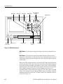
Rear-panel Connectors
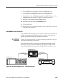
Figure 2-2 shows the locations of the MTX100A rear-panel connectors.
Clock/Ref In
Trig In/Out
Clock/Ref
In
SPI In/Out
SPI
In/Out
Trig
In/Out
IEEE 1394b
Printer
VGA
Printer
VGA
Expansion card slot
LAN
Com
LAN
Com
IEEE 1394b
Power
Figure 2-2: MTX100A rear panel
Expansion Card Slot. You can install one of the optional interface cards in this slot.
Refer to Optional Interface Cards on page 2-11 for detailed information about the
available interface cards.
Clock/Ref In. Use this BNC connector to input an external reference signal or clock
signal. Refer to Appendix A: Specifications for detailed information about the
signal specification.
NOTE. Use a continuous signal for an external reference or clock signal.
Trig In/Out. Use this BNC connector to input an external trigger event for stream
recording or output a 27 MHz reference clock signal or an ISDB-T frame pulse
signal. You can change the configuration from the Play menu (refer to the Play
Menu on page 3-5).
Refer to Appendix A: Specifications for detailed information about the signal
specification.
2-4
MTX100A MPEG Recorder & Player User Manual
Operating Basics
SPI In/Out. Use this 25-pin D-sub connector to input or output an SPI (Synchronous
Parallel Interface) signal.
Printer. Use this 25-pin D-sub connector to connect a printer. This interface
supports the IEEE 1284 parallel port standard.
IEEE1394b. Use this connector to connect an IEEE1394b device such as an external
hard disk drive.
VGA. Use this 9-pin D-sub connector to display the instrument screen to an external
monitor.
The VGA output is automatically enabled only when you power on the instrument
with an external monitor connected. If you want to enable the VGA output after
powering on the instrument, perform the following steps:
1. Minimize the Play screen to display the Windows XP desktop.
2. Click the Intel(R) Extreme Graphics 2M icon (see below) at the right side of
the taskbar.
3. Select Graphic Options > Output To > Intel(R) Dual Display Clone >
Monitor+Notebook from the displayed menu.
LAN. (10/100/1000 Base-T). Use this connector to connect the MTX100A to your
local Ethernet network.
Com. This 9-pin D-sub connector provides a serial interface for instrument control.
Power. Use this connector to apply power to the instrument using the supplied
power cord.
Display Elements
There are two types of display screens to operate the MTX100A; the Play screen
and the Record screen.
Play screen is used to output the selected stream. When you power on the
instrument, this screen will display the last screen showing before powering
down.
Record screen is used to record the input stream. When you press the REC
button or select the Record command from the File menu while the Play screen
is displayed, the screen switches to the Record screen.
MTX100A MPEG Recorder & Player User Manual
2-5
Operating Basics
This subsection explains the display elements that make up the Play and Record
screens.
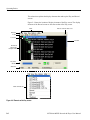
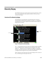
Figure 2-3 shows the location of display elements of the Play screen. The display
elements of the Record screen are the same as that of the Play screen.
Menu
Remote connection status icons
Menu bar
Toolbar
Icon cursor
Scroll bar
Hierarchical
display of the
transport stream
Play status
indicator
Status bar
Menu commands list
Figure 2-3: Elements of the Play screen
2-6
MTX100A MPEG Recorder & Player User Manual
Operating Basics
Menu Bar. The Menu bar displays the names of the menus that can be used in the
Play or Record screen. Press the MENU button to enable or disable the menus.
Refer to Using the Menus on page 3-3 for detailed information about the menus.
Toolbar. The toolbar provides shortcut buttons for many of the most often used
menu commands. Click a toolbar button to select the corresponding command.
You can toggle the toolbar display on and off using Toolbar command in the View
menu.
Refer to Toolbar Buttons on page 3-34 for detailed information about the function
of each toolbar button.
Hierarchy Display. Each icon in the hierarchy display represents an element of the
stream. The hierarchy text contains a description of the associated icon.
Refer to Hierarchy Display on page 3-37 for detailed information about the
hierarchy icons.
Icon Cursor. The icon cursor appears as a red box around an icon in the hierarchy
to indicate the currently selected icon.
Use the up (S) or down (T) arrow button to move the icon cursor between icons.
When the icon cursor is at the top or bottom of the hierarchy display, the hierarchy
scrolls to show additional elements of the stream when applicable.
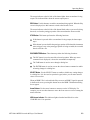
Play/Record Status Indicator. The play status indicator (see Figure 2-4) is displayed
while the selected stream is being output. It shows the output status of the selected
stream: the progress of the stream output, the output source, the operational status,
and the elapsed time.
The record status indicator is displayed while the input stream is being recorded. It
shows the record status of the input stream: the progress of the stream record, the
record target, and the elapsed time.
1
2
3
4
Figure 2-4: Play status indicator
MTX100A MPEG Recorder & Player User Manual
2-7
Operating Basics
The play/record status indicator shows the following information:
1. Position Indicator. In the Play screen, this indicator shows the progress of the
stream output using the duration gauge. In the Record screen, this indicator
shows the progress of the stream record using the duration gauge.
The duration gauge is updated every 1 second. If you output a stream with a
repetition rate of around 3 seconds, the gauge may not be displayed correctly.
2. Output Source/Record Target. In the Play screen, this indicator shows the
output source used to output the selected stream. In the Record screen, this
indicator shows the record target used to record the input stream.
Either of the following icons are displayed according to the selected output
source or record target:
This icon shows that the hard disk is the output source or record target.
This icon shows that the RAM is the output source or record target.
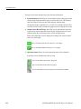
3. Operation Status. Shows the current operation status of the instrument.
In the Play screen, the following icons are used:
This icon shows that the selected stream is being output.
This icon shows that the stream output is being stopped.
This icon shows that the selected stream is being read from the hard disk to the RAM.
2-8
MTX100A MPEG Recorder & Player User Manual
Operating Basics
In the Record screen, the following icons are used:
This icon shows that the captured stream is being recorded.
This icon shows that the stream record is being stopped.
This icon shows that the MTX100A waits for a trigger event.
This icon shows that a trigger event occurs.
This icon shows that the captured stream is being processed on the hard disk.
This icon shows that the captured stream is being saved from the RAM to the hard disk.
4. Elapsed Time. In the Play screen, this box displays the elapsed time of the
current stream data output.
In the Record screen, this box displays the elapsed time since the input stream
was recorded.
Scroll Bar. The scroll bar appears when there is a hierarchy display to show the
relative position of the hierarchy of the stream.
NOTE. After you scroll a hierarchy display in the Record screen, the display may
be out of focus. If this is the case, select an icon cursor on the display to refocus.
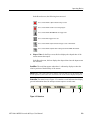
Status Bar. The status bar (see Figure 2-5) contains several indicators that display
general information about the transport stream output or record status.
1
2
3
4
5
6
Figure 2-5: Status bar
MTX100A MPEG Recorder & Player User Manual
2-9
Operating Basics
The status bar shows the following information:
1. Standard. In the Play screen, this indicator shows the standard used to display
the selected stream (MPEG2, ARIB, DVB, ATSC, S-TMCC, M-TMCC, or
Non TS). In the Record screen, this indicator shows the standard used to
display the input stream.
2. Packet Size. In the Play screen, this indicator displays the packet size in bytes
(188, 204, 208, Non TS, or Partial TS (Option 05 only)) of the stream output.
In the Record screen, this indicator displays the packet size in bytes of the input
stream.
3. Clock Source. This indicator displays the source of the reference clock
(internal or external) used for the stream output.
4. Bit Rate. In the Play screen, this indicator displays the bit-rate (in Mbps) of the
stream output. In the Record screen, this indicator displays the bit-rate (in
Mbps) of the input stream.
5. RAM free space. In the Play screen, this indicator shows the RAM free space
that can be used to output the selected stream. In the Record screen, this
indicator shows the RAM free space that can be used to record the input
stream.
6. Output Source/Record Target. In the Play screen, this indicator shows the
output source used to output the selected stream. In the Record screen, this
indicator shows the record target used to record the input stream.
This indicator is the same as the output source/record target indicator of the
Play/Record Status indicator.
Remote Connection Status Icons. The remote connection status icons appear when
a TCP/IP connection for remote control is established. The right icon shows the
status of the TCP/IP connection (this icon is always displayed when the TCP/IP
connection is established), and the left icon shows the lock status of the front-panel
buttons and mouse input.
There are two display states:
This shows that the TCP/IP connection for remote control is established.
This shows that the TCP/IP connection for remote control is established and the
front-panel buttons and mouse input are locked by the :SYSTem:KLOCk:STATe ON
command.
2-10
MTX100A MPEG Recorder & Player User Manual
Test Equipment Depot - 800.517.8431 - 99 Washington Street Melrose, MA 02176 - FAX 781.665.0780 - TestEquipmentDepot.com
Operating Basics
To reset the lock status, send the :SYSTem:KLOCk:STATe OFF command or
press the ESC button on the front panel (if a keyboard is connected, press the Esc
key).
When the TCP/IP connection is closed, the remote status icons disappear.
Optional Interface Cards
The MTX100A is equipped with a card slot on the rear panel to install one of the
following optional interface cards:
ASI interface (Option 01)
Universal parallel/serial interface (Option 02)
IEEE1394/ASI interface (Option 05)
SMPTE310M/ASI/SPI interface (Option 07)
This subsection describes these interface options and their functions.
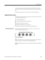
ASI Interface (Option 01)
Figure 2-6 shows the ASI interface. Refer to Appendix A: Specifications for
detailed specifications of the interface.
ASI In
2
ASI Out
1
Figure 2-6: ASI interface
ASI In. Use this BNC connector to input an ASI (Asynchronous Serial Interface)
signal. The left side of the connector has a loopthrough output.
ASI Out. Use this BNC connector to output an ASI (Asynchronous Serial Interface)
signal.
MTX100A MPEG Recorder & Player User Manual
2-11
Operating Basics
Universal Parallel/Serial
Interface (Option 02)
Figure 2-7 shows the universal parallel/serial interface. Refer to Appendix A:
Specifications for detailed specifications of the interface.
Event Out
Universal In/Out
Figure 2-7: Universal parallel/serial interface
Event Out. Use this BNC connector to output an event signal. This signal is the
same as the PSYNC signal of the parallel output.
Universal In/Out. Use this connector to input or output an ECL/TTL/LVDS signal
in a parallel or serial format.
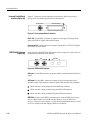
IEEE1394/ASI Interface
(Option 05)
Figure 2-8 shows the IEEE1394/ASI interface. Refer to Appendix A: Specifications
for detailed specifications of the interface.
Input
ASI
IEEE1394
Output
Figure 2-8: IEEE1394/ASI interface
ASI Input. Use this BNC connector to input an ASI (Asynchronous Serial Interface)
signal.
ASI Output. Use this BNC connector to output an ASI (Asynchronous Serial
Interface) signal. This connector outputs a signal under the following conditions:
While a stream is being output from the IEEE1394 connector.
While a stream is being recorded using the IEEE1394 connector.
While a stream is being recorded using the ASI Input connector.
IEEE1394. Use these 4-pin IEEE1394 connectors to connect IEEE1394 device(s)
such as a BS/CS tuner or a D-VHS recorder. Refer to Using the IEEE1394
Interface (Option 05 Only) on page 3-125 for detailed information on how to send
or receive a transport stream using the IEEE1394 connector.
2-12
MTX100A MPEG Recorder & Player User Manual
Operating Basics
SMPTE310M/ASI/SPI
Interface (Option 07)
Figure 2-9 shows the SMPTE310M/ASI/SPI interface. Refer to Appendix A:
Specifications for detailed specifications of the interface.
SMPTE310M/ASI
Output
Input
SPI
Input
Figure 2-9: SMPTE310M/ASI/SPI interface
NOTE. The SMPTE310M interface supports the data rates of 19.392658 Mbps
(8 VSB, 188 bytes packet size).
SMPTE310M/ASI Output. Use these BNC connectors to output a SMPTE310M or an
ASI (Asynchronous Serial Interface) signal. You can select the output signal
format from the 310M/ASI/SPI menu (refer to 310M/ASI/SPI Menu on page 3-22).
SMPTE310M/ASI Input. Use this BNC connector to input a SMPTE310M signal or
an ASI (Asynchronous Serial Interface) signal. You can select the input signal
format from the 310M/ASI/SPI menu (refer to 310M/ASI/SPI Menu on page 3-33).
SPI Input. Use this 25-pin D-sub connector to input an SPI (Synchronous Parallel
Interface) signal.
NOTE. The SPI Input connector can only be used to input a signal.
MTX100A MPEG Recorder & Player User Manual
2-13
Operating Basics
Basic Menu Operation
This section describes the basics of using the MTX100A menu and the methods for
entering numeric input in the various dialog boxes.
The menus are displayed in the menu bar at the top of the Play or Record screen.
You can operate these menus using the front panel MENU button, ESC button,
TAB button, ENTER button, and the arrow buttons (see Figure 2-10).
ESC button
TAB button
ENTER button
MENU button
Arrow buttons
Figure 2-10: Front panel showing the menu controls
Accessing Menu Commands. To access any menu command, press the MENU
button. When you press the MENU button, the File menu command list opens.
Use the up (S) or down (T) arrow button to move through the command list. Press
the ENTER button to execute the selected command.
Use the left (W) or right (X) arrow button to select the desired menu. Press the ESC
button to close the command list temporarily.
Press the MENU button again to close the menu command list.
2-14
MTX100A MPEG Recorder & Player User Manual
Operating Basics
NOTE. When you press the left arrow button while the File menu is displayed or
when you press the right arrow button while the Utility menu is displayed, the
Windows Control menu appears.
Display States of the Menu Commands. The menu commands can have the
following three display states as shown in Figure 2-11:
A command followed by “X” indicates that a corresponding submenu will be
displayed after you press the ENTER button or the right (X) arrow button.
A command followed by an ellipsis (...) indicates that a corresponding dialog
box will open after you press the ENTER button.
A command name by itself will be executed after you press the ENTER button.
A corresponding submenu will be
displayed
A corresponding dialog box will be
displayed when this command is executed
The displayed command will be executed
immediately
Figure 2-11: Display status of the menu commands
Numeric Input
You can enter numeric values in the displayed dialog box by using the keypad or
by using the arrow buttons.
Numeric Input Using the Keypad. Perform the following procedure to input numeric
values by using the keypad. Figure 2-12 shows the keypad.
1. Open a dialog box including the text box in which you want to change a
parameter.
2. Press the TAB button repeatedly to select (highlight) the numeric parameter
you want to change in the open dialog box.
MTX100A MPEG Recorder & Player User Manual
2-15
Operating Basics
3. Press the SELECT button to open the keypad (see Figure 2-12).
Numeric input box
Clear key
Backspace
Cancel key
Enter key
Figure 2-12: Keypad
4. Press the TAB button or the arrow buttons to move the dotted line box onto the
number you want to input (when the keypad first opens, the box is located on
the ENT key).
5. Press the SELECT button. This displays the selected number in the numeric
input box.
6. Repeat steps 4 and 5 to input the desired parameter value.
7. Press the ENTER button (or select the ENT key and then press the SELECT
button). This saves the new value in the numeric input box and closes the
keypad.
Numeric Input Using the Arrow buttons. Perform the following procedure to change
a value by using the arrow buttons:
1. Open the dialog box containing the text box where you want to change a
parameter.
2. Press the TAB button repeatedly to select the numeric parameter you want to
change in the open dialog box.
3. Press the left (W) arrow button to begin editing the parameter. This highlights
the last digit.
4. Press the left (W) or right (X) arrow button to move the highlighted cursor to
the value you want to change.
5. Press the up (S) or down (T) arrow button to increase or decrease the value.
6. Repeat steps 4 and 5 to enter all of the desired values. To add a digit, press the
left (W) arrow button.
2-16
MTX100A MPEG Recorder & Player User Manual
Operating Basics
7. After you change all of the values, press the ENTER button.
About the Data Output Source
When you output the selected stream data, you can select either the hard disk or the
RAM as the output source. This subsection describes the operation of the
MTX100A when each output source is selected.
RAM
When you select the RAM as the output source, the MTX100A performs the
following:
When data output rate is less than or equal to 120 Mbps, the MTX100A outputs
the first stream data while transferring the data from the hard disk to the RAM
and then continuously outputs the data from the RAM using looping methods.
When data output rate is more than 120 Mbps, the MTX100A continuously
outputs a stream data from the RAM using looping methods after the data is
completely transferred from the hard disk to the RAM.
If you select the RAM as the output source, you cannot output the data over the
RAM free space for the data output (maximum 256 MB). This RAM free space is
displayed on the status bar. Refer to Status Bar on page 2-9, for more information
about the status bar.
Hard Disk
If you select the hard disk (Disk) as the output source, the MTX100A always
outputs the selected stream data from the hard disk regardless of the data output
rate. When the reading speed of the hard disk cannot overtake the data output rate,
the error message “Error: Output Buffer Empty” appears.
Use the Source command in the Play menu to select the output source. Refer to
Play Menu on page 3-5 for more information about the Play menu.
You can see the currently selected output source in the status bar. Refer to Status
Bar on page 2-9, for more information about the status bar.
MTX100A MPEG Recorder & Player User Manual
2-17
Operating Basics
2-18
MTX100A MPEG Recorder & Player User Manual
Tutorials
This section provides the following tutorials to familiarize you with the basic
functions of the MTX100A:
Outputting a transport stream
Recording a transport stream
NOTE. These tutorials do not cover all the features and functions of the MTX100A.
The tutorials are intended to introduce you to the operations required to execute the
instrument's basic functions.
Refer to the Reference section for detailed descriptions of the menus and functions
used in these procedures.
Before you perform these tutorials, make sure that the MTX100A is properly
installed. Refer to Installation on page 1-5.
Required Equipment
Table 2-1 lists the equipment required to perform the tutorials. Accuracy of
alternate equipment should equal or exceed that of the example instruments and
accessories. Using inadequate equipment may result in inaccurate measurements.
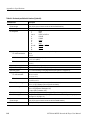
Table 2-1: Tutorial recommended test equipment and accessories
Item
MPEG test system
No.
1
Requirement
Real-time transport stream analyzer
Interface cable
1
D-sub, 25 pin
MTX100A MPEG Recorder & Player User Manual
Example
Tektronix MTS400 Series MPEG Test
Systems or equivalent
Tektronix part number 012-A022-00
(provided with the instrument)
2-19
Tutorials
Outputting a Transport Stream
The hard disk drive of the MTX100A is shipped with files containing
factory-supplied samples of transport streams. This tutorial opens one of these
sample files and outputs the transport stream.
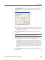
Perform the following steps to select and output a stored transport stream:
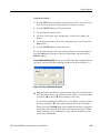
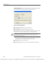
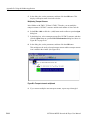
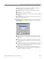
1. Press the front-panel PLAY button to display the Play screen.
2. Press the MENU button to open the File menu.
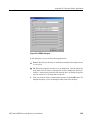
3. Press the up (S) or down (T) arrow button to select Open from the menu, and
then press the ENTER button to open the Select File dialog box shown in
Figure 2-13.
Figure 2-13: Select File dialog box
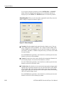
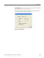
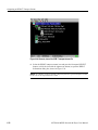
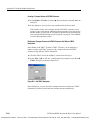
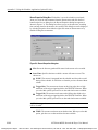
4. Press the up (S) or down (T) arrow button to select the test64.TRP file, and
then press the ENTER button. This displays the hierarchy view of the transport
stream file shown in Figure 2-14.
2-20
MTX100A MPEG Recorder & Player User Manual
Tutorials
Figure 2-14: Hierarchy view of the transport stream file
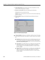
5. Connect the interface cable between the SPI In/Out connector on the
MTX100A rear panel to the SPI In connector of the MPEG test system.
6. Press the MTX100A PLAY button to start the transport stream output.
When transport stream output is started, the play status indicator (see Figure 2-15)
appears and the PLAY indicator at the left side of the button lights.
Figure 2-15: Play status indicator
7. Set up the MPEG test system to monitor the transport stream output from the
MTX100A. Figure 2-16 shows the transport stream data displayed on an
MPEG test system.
8. Press the STOP button on the MTX100A to stop the transport stream output.
Observe that the Play Status indicator disappears.
MTX100A MPEG Recorder & Player User Manual
2-21
Tutorials
Figure 2-16: Transport stream display from an MPEG test system
Recording a Transport Stream
This tutorial captures a transport stream being applied into the SPI In/Out
connector and records it on the hard disk as a file.
Perform the following steps to capture a transport stream and record it in the hard
disk as a file:
1. Press the front-panel REC button to display the Record screen.
Since no signal is being applied at this time, the No Signal message appears on
the top of the screen (see Figure 2-17).
Figure 2-17: No Signal message
CAUTION. Connect the interface cable before applying a signal to the SPI In/Out
connector. If you connect the cable while a signal is being output, the MTX100A
may not function correctly.
2-22
MTX100A MPEG Recorder & Player User Manual
Tutorials
2. Connect the interface cable between the SPI In/Out connector on the
MTX100A rear panel to the SPI connector of the MPEG test system.
3. Output a transport stream from the MPEG test system.
When transport stream output is started, the hierarchy view of the transport
stream is displayed on the Record screen of the MTX100A.
4. Press the MTX100A REC button.
When you press the button, the record status indicator (see Figure 2-18)
appears and the REC indicator at the left side of the button lights.
Figure 2-18: Record status indicator
After the transport stream record is completed, the record status indicator
disappears, and the transport stream is saved automatically with a file name which
shows the current date (yy:mm:dd).
MTX100A MPEG Recorder & Player User Manual
2-23
Tutorials
2-24
MTX100A MPEG Recorder & Player User Manual
Reference
Reference
The Reference section is divided into the following subsections:
Using the Menus describes the function of each selection available in the
menus.
Hierarchy Display describes the icons used by the MTX100A to represent
transport stream elements.
Adding Jitter to PCRs provides instructions and procedures on how to add jitter
to PCRs.
Continuous Recording Feature describes features and basic action of
Continuous Recording.
Preset File provides information about the preset file and procedures on how
to save and load a preset file.
Connecting to a Network provides procedures to connect the MTX100A to
your network.
Outputting an ISDB-T Transport Stream provides the procedure to output an
ISDB-T transport stream from the MTX100A.
Syntax defines the command syntax and processing conventions.
Remote Commands provides the remote commands set used in the MTX100A.
Default Settings lists the default settings of the remote commands.
Error Messages and Codes lists the codes and messages used in the status and
event reporting system in the MTX100A.
Network Interface Specifications describes the MTX100A network interface
specifications.
Using the IEEE1394 Interface (Option 05 Only) explains how to connect the
MTX100A Option 05 and an IEEE1394 device(s), and how to set up the
MTX100A Option 05.
MTX100A MPEG Recorder & Player User Manual
3-1
Reference
3-2
MTX100A MPEG Recorder & Player User Manual
Using the Menus
This section describes the function of each selection available in the menus. This
section is divided into the following subsections:
Menus in the Play Screen describes all of the menu commands and their
features available in the Play screen.
Menus in the Record Screen describes all of the menu commands and their
features available in the Record screen.
Toolbar Buttons describes the toolbar buttons and their functions.
Refer to Basic Menu Operation on page 2-14 for information about how to operate
the menus.
Menus in the Play Screen
This subsection describes the menus available in the Play screen.
File Menu
The File menu in the Play screen contains commands for selecting a stream file and
for loading and saving a preset file. This menu also contains commands for exiting
the MTX100A application and for shutdown of the instrument. Table 3-1 describes
the commands in the File menu.
Table 3-1: File menu commands (Play screen)
Command
Open
Load Preset
Save Preset
RECORD
Minimize
MTX100A MPEG Recorder & Player User Manual
Description
Opens a stream file stored in the E: drive (volume E). When a file is
selected, the MTX100A checks the packet size of the file. When it is a
transport stream file, its data is output in packets. Therefore, if an
incomplete packet is included at the start or end point of the file, the
portion is not output. The available minimum data size is 104 Kbyte.
When you select this command, the Select File dialog box appears. Refer
to Select File Dialog Box on page 3-4 for more information.
Loads the specified preset file (*.set). When a preset file is loaded, the
current instrument settings are changed by the file's content. Refer to
Preset File beginning on page 3-63 for more information about the preset
file.
Saves the current instrument settings as a preset file. Refer to Preset File
beginning on page 3-63 for more information about the preset file.
Switches to the Record screen.
Minimizes the MTX100A application window.
3-3
Using the Menus
Table 3-1: File menu commands (Play screen) (cont.)
Command
Exit
Shutdown
Description
Quits the MTX100A application. The MTX100A application settings are
saved.
Quits the MTX100A application and shuts down the MTX100A.
Select File Dialog Box. When you select the Open command from the File menu,
the Select File dialog box appears as shown in Figure 3-1.
Figure 3-1: Select File dialog box
Press the arrow buttons to select the desired file, and then press the ENTER button
to load the highlighted file.
Select Up One Level to move from the current directory to the directory one level
higher.
When you select the “...” button at the upper right side of the dialog box, the Select
File dialog box is displayed, and you can select the other file.
View Menu
3-4
The View menu contains commands that control the display of the Toolbar and
Status bar. Table 3-2 describes the commands available in the View menu.
MTX100A MPEG Recorder & Player User Manual
Test Equipment Depot - 800.517.8431 - 99 Washington Street Melrose, MA 02176 - FAX 781.665.0780 - TestEquipmentDepot.com
Using the Menus
Table 3-2: View menu commands
Command
Toolbar
Status Bar
Play Menu
Description
Toggles the display of the Toolbar on and off in the Play screen. A check
mark precedes the command in the menu when the Toolbar is selected
for display.
Toggles the display of the Status bar on and off in the Play screen. A
check mark precedes the command in the menu when the Status bar is
selected for display.
The Play menu contains commands for defining output parameters such as packet
size, output clock rate, or output source. Table 3-3 describes the commands
available in the Play menu.
Table 3-3: Play menu commands
Command
Packet Size
Description
Sets the packet size (in bytes) for the stream. You can set the packet size
to 188 (188 + 0), 204 (188 + 16), 208 (188 + 20) bytes, or Non TS.
These packet sizes can only be set for an MPEG2 transport stream. For
an S-TMCC or M-TMCC transport stream, the packet size is fixed to 204.
For a Non TS stream, the packet size is fixed to Non TS. In addition, if
you select 8VSB for an output signal format in Option 07, the packet size
is fixed to 188.
Clock
Update
Sync
When you select Non TS, the MTX100A deals with stream data in a byte
unit (not a packet unit) and outputs all of the data in a file. If a transport
stream contains any error, you can output it by selecting Non TS.
Opens the Clock dialog box where you can set the clock rate of the
stream output. Refer to Clock Dialog Box on page 3-7 for more
information.
Sets whether to update parameters in the stream when looped. You can
select On or Off. You cannot set to On for a Non TS stream.
You can select which parameters in the stream are updated using the
Others dialog box. Refer to Others Dialog Box on page 3-14 for more
information.
Sets the format of the PSYNC signal output from the SPI IN/OUT
connector. You can select TS Packet, SF, or Non TS. For TS Packet, a
single pulse signal is output at the start point of each packet. For SF, a
single pulse is output at the start point of the SF appearing every 204 X
48 X8 bytes. For Non TS, the Set Non-TS Sync dialog box appears,
where you can enable the PSYNC and DVALID signals.
Refer to Set Non-TS Sync Dialog Box on page 3-9 for more information.
MTX100A MPEG Recorder & Player User Manual
3-5
Using the Menus
Table 3-3: Play menu commands (cont.)
Command
PCR Initial Value
Source
Loop
Start/Stop
Auto Play
Timer Play
Other
Description
Opens the PCR Initial Value dialog box where you can set the initial value
of the program_clock_reference_base and
program_clock_reference_extension parameters when the transport
stream is output.
Refer to PCR Initial Value Dialog Box on page 3-10 for more information.
Selects the source for stream output. You can select RAM or Disk.
Refer to About the Data Output Source on page 2-17 for detailed
information about differences between the two sources.
Sets whether or not the stream is output using the looping method. You
can select On or Off. If you select On, the selected stream is continuously
output. If you select Off, the selected stream is output once.
Opens the Start/Stop Position dialog box where you can set the start and
stop position of the stream, and initial start position of the stream for loop
output.
Refer to Start/Stop Position Dialog Box on page 3-11 for more
information.
Sets whether or not the transport stream is automatically output using the
last power-down settings when you turn on the MTX100A on. You can
select On or Off. If you select On, take care of the output level setting
used when the MTX100A was last turned off and the input level of the
instrument (device) currently connected to the MTX100A.
Opens the Timer Play/Record dialog box where you can set the date and
time used to output a stream automatically.
Refer to Timer Play/Record Dialog Box on page 3-13 for more
information.
Opens the Other dialog box where you can set the standard used to
display the selected stream and display radix for the text information.
Refer to Others Dialog Box on page 3-14 for more information.
3-6
MTX100A MPEG Recorder & Player User Manual
Using the Menus
Clock Dialog Box. When you select the Clock command from the Play menu, the
Clock dialog box appears as shown in Figure 3-2.
Numerator
Denominator
Figure 3-2: Clock dialog box
Clock Source: Sets which clock will be used as the reference for the stream
output. Press the TAB button repeatedly to select an item in the field, and then
press the left (W) or right (X) arrow button to select the desired clock source.
You can select from the following settings:
Internal uses the internal clock of the MTX100A as the clock reference.
Ext Ref allows you to input a signal on the Clock/Ref In connector for use as
the clock reference. When you select the button to the right of the ExtRef box,
the following External Reference dialog box appears.
MTX100A MPEG Recorder & Player User Manual
3-7
Using the Menus
10 MHz: Selects a 10 MHz signal on the Clock/Ref In connector.
27 MHz: Selects a 27 MHz signal on the Clock/Ref In connector.
ISDB-T IFFT Clock: Selects a signal corresponding to the IFFT sample
clock rate (8.126984 MHz) on the Clock/Ref In connector.
Press the TAB button repeatedly to select an option button, and then press
the arrow buttons to select one of the options.
Ext P Clk (external parallel clock) allows you to input a clock signal on the
Clock/Ref In connector for use as the parallel clock.
Ext S Clk (external serial clock) allows you to input a clock signal on the
Clock/Ref In connector for use as the serial clock.
Data Rate: Sets the clock rate for the transport stream output. You can enter
the clock rate using the following methods (the first method provides greater
clock-rate precision):
Enter values into the numerator and denominator text boxes (see Figure 3-2 on
page 3-7). The MTX100A will then calculate the clock rate based on the ratio
of the numerator and denominator values.
Enter a value into the clock rate text box. The MTX100A will then calculate
the numerator and denominator text boxes based on the clock rate.
When you use the Ext P Clk or Ext S Clk mode, set the clock rate to the same
value as the input clock signal. Also, when you use the Ext S Clk mode, you
cannot set the value more than 32 Mbps.
Press the TAB button repeatedly to select the value you want to change, and
then press the SELECT button to open the keypad. Use the keypad to enter the
desired value.
Fixed ES Rate: Sets whether the elementary stream rate is fixed or not. When
it is checked, the elementary stream rate becomes constant regardless of the
clock rate setting. If you fix the elementary stream rate, you cannot set the
output clock rate (Data Rate) more than the data rate set when the stream file
was downloaded.
Press the TAB button to select the check box, and then press the SELECT
button to toggle the check box on (checked) or off (not checked).
When the Fixed ES Rate check box is enabled, PCR/PTS/DTS Update Method
in the Select Update Item dialog box (see page 3-18) is set to Hardware
automatically.
Default Rate: Displays the default clock rate and packet size and then changes
the values. When you select this button, the following Default Clock dialog
box appears.
3-8
MTX100A MPEG Recorder & Player User Manual
Using the Menus
Default Data Rate: Changes the default clock rate when the selected stream
file was downloaded.
Since the default clock rate is calculated based on the PCRs in the downloaded
stream file, the value can be different than the original clock rate. When the
elementary stream rate is fixed (refer to the Fixed ES Rate description), the
instrument refers to the default clock rate. Therefore, if the default clock rate
is different than the original clock rate, you need to set the value to the
appropriate value. If you change the value, the clock rate value in the Data Rate
dialog box is also changed.
Packet Size: Changes the default packet size when the selected stream file is
downloaded. If you change the value, the Packet Size setting in the Play menu
will also change.
Press the ENTER button to enable all setting changes.
Set Non-TS Sync Dialog Box. When you select the Non-TS from the Sync
command in the Play menu, the Set Non-TS Sync dialog box appears as shown in
Figure 3-3.
Figure 3-3: Set Non-TS Sync dialog box
MTX100A MPEG Recorder & Player User Manual
3-9
Using the Menus
Psync Enable: Sets the status of the PSYNC signal output from the SPI In/Out
connector. Press the TAB button repeatedly to select this item, and then press
the SELECT button to toggle the check box on (checked) or off (not checked).
Interval: Sets the output period of the PSYNC signal in the range of 16 to 255
bytes. This value needs to be set equal to or greater than the Width value in the
Dvalid field. Press the TAB button repeatedly to select the box, and press the
up (S) or down (T) arrow button to set the value.
Dvalid Enable: Sets the status of the DVALID signal output from the SPI
In/Out connector. Press the TAB button repeatedly to select this item, and then
press the SELECT button to toggle the check box on (checked) or off (not
checked).
Width: Sets the data width of the DVALID signal in the range of 16 to 255
bytes. Press the TAB button repeatedly to select the box, and then press the up
(S) or down (T) arrow button to set the value.
Press the ENTER button to enable all setting changes.
PCR Initial Value Dialog Box. When you select the PCR Initial Value command
from the Play menu, the PCR Initial Value dialog box appears as shown in
Figure 3-4.
Figure 3-4: PCR Initial Value dialog box
Base Value: Sets the initial value for the program_clock_reference_base
value. You can set the value from 0 to 8589934591. The bracketed number
represents the number of bits for the program_clock_reference_base field.
Press the TAB button repeatedly to select the text box, and then press the
SELECT button to open the keypad. Use the keypad to set the desired value.
3-10
MTX100A MPEG Recorder & Player User Manual
Using the Menus
Extension Value: Sets the initial value for the program_clock_reference_
extension value. You can set the value from 0 to 299. The bracketed number
represents the number of bits for the program_clock_reference_extension
field.
Press the TAB button repeatedly to select the text box, and then press the
SELECT button to open the keypad. Use the keypad to set the desired value.
Start/Stop Position Dialog Box. When you select the Start/Stop command from the
Play menu, the Start/Stop dialog box appears as shown in Figure 3-5.
Slider
Figure 3-5: Start/Stop Position dialog box
Start: Sets the start position of the stream by time (h:m:s) or the number of
packets (the number of super frames for a M-TMCC file, or the number of
bytes for a Non TS file). Use the Format list box to select the way to set the
position.
Stop: Sets the stop position of the stream by time (h:m:s) or the number of
packets (the number of super frames for a M-TMCC file, or the number of
bytes for a Non TS file). Use the Format list box to select the way to set the
position.
Initial: Sets the initial start position of the stream for loop output. You can set
the value by time (h:m:s) or the number of packets (the number of super frames
for a M-TMCC file, or the number of bytes for a Non TS file). Use the Format
list box to select the way to set the position.
Play: Shows the actual time or number of packets (the number of super frames
for a M-TMCC file, or the number of bytes for a Non TS file) that is calculated
by the values of the Start and Stop text boxes.
MTX100A MPEG Recorder & Player User Manual
3-11
Using the Menus
Format: Specifies the way to set the start, stop, and initial positions of the
stream. For a transport stream file, you can select Time or Packets. For a
M-TMCC file, you can select Time or SF (super frame). For a Non TS file, you
can select Time or Bytes.
For an ISDB-T file, the start packet is defined as the first-appearing packet
including an OFDM frame start flag after the specified start position. The stop
packet is defined as the packet at the front of the last-appearing packet
including an OFDM frame start flag before the specified stop position. At this
time, if the number of OFDM frames between the start packet and stop packet
is not an even number, the packet in the last OFDM frame becomes the stop
packet.
There are two ways to set the start, stop, and initial positions: using the slider (see
Figure 3-5) to set them or using the text boxes to enter values directly.
Using the slider:
1. For the start and stop positions:
a. Press the TAB button repeatedly to select the slider. When the slider is
selected, broken lines are shown around it.
b. Press the left (W) or right (X) arrow button to move the slider to the place
you want to set the start position.
c. Press the TAB button repeatedly to select the Stop option button, and then
press the SELECT button.This moves the slider to the right end.
d. Press the TAB button repeatedly to select the slider. When the slider is
selected, broken lines are shown around it.
e. Press the left (W) or right (X) arrow button to move the slider to the place
you want to set the stop position.
f.
Press the ENTER button to enable the values.
2. For the initial start position for loop output:
a. Press the TAB button repeatedly to select the Initial check box, and then
press the SELECT button. A red arrow appears on the slider.
b. Press the TAB button repeatedly to select the red arrow. When the arrow
is selected, broken lines are shown around it.
c. Press the left (W) or right (X) arrow button to move the slider to the place
you want to set the initial start position.
d. Press the ENTER button to enable the value.
3-12
MTX100A MPEG Recorder & Player User Manual
Using the Menus
Using the text boxes:
1. Press the TAB button repeatedly to select the Start text box. If you set a time,
select one of the text boxes for setting the hour, minute, or second.
2. Press the SELECT button. The keypad appears.
3. Use the keypad to enter the value.
4. If you set a time, repeat step 1 through step 3 to set the hour, minute, and
second.
5. Use the same procedure given in step 1 through step 4 to set the value in the
Stop text box.
6. Press the ENTER button to enable the values.
To reset all of the settings to the values when the dialog box was first displayed,
press the TAB button repeatedly to select the Reset button, and then press the
SELECT button.
Timer Play/Record Dialog Box. When you select the Timer Play command from the
Play menu, the Timer Play/Record dialog box appears as shown in Figure 3-6.
Figure 3-6: Timer Play/Record dialog box
Start at: Sets the date and time when the stream output or record starts. Press
the TAB button to select year, month, date, hour, minute, or second, and then
press the up (S) or down (T) arrow button to set the value.
If a mouse is connected to the MTX100A, you can display a calendar for date
setting by clicking the T arrow button at the right side of the date display,
When you press the ENTER button after setting the date and time, a dialog box
showing the current date and time, and set date and time is displayed. When
the date and time arrives, the dialog box closes and stream output or stream
record starts automatically.
MTX100A MPEG Recorder & Player User Manual
3-13
Using the Menus
If you want to cancel the operation, press the ENTER, ESC, or SELECT
button. When the dialog box that prompt you to confirm the operation is
displayed, press the SELECT or ENTER button to execute the operation.
Others Dialog Box. When you select the Other command from the Play menu, the
Others dialog box appears as shown in Figure 3-7.
Figure 3-7: Others dialog box
Standard: Sets the standard used on the hierarchy-display screen. You can
select ARIB, ATSC, DVB, or MPEG2. For a transport stream (ARIB, ATSC,
DVB, or MPEG2), the standard is set to the previous setting as a default. For
an S-TMCC, M-TMCC, or ISDB-T transport stream, you need to select ARIB
for proper display.
Press the TAB button repeatedly to select the list box, and then press the arrow
buttons to select one of the standards.
Numeric: Sets the base value used to describe the component information in
the hierarchy display. You can select Decimal, Hex, or Octal.
Press the TAB button repeatedly to select the list box, and then press the arrow
buttons to select one of the base values.
Ext Play Start: Sets whether or not to start stream output using a trigger signal
applied to the Trig In/Out connector. You can select Off, Rise, or Fall. When
you select Rise, the stream output is started at the rising edge of the applied
trigger signal. When you select Fall, the stream output is started at the falling
edge of the applied trigger signal.
Press the TAB button repeatedly to select the list box, and then press the arrow
buttons to select one of the external play modes.
3-14
MTX100A MPEG Recorder & Player User Manual
Using the Menus
SPI Output Enable: Sets whether the signal output from the SPI In/Out
connector is enabled or not. Use this function to set the SPI In/Out connector
to input only and the Universal In/Out connector to output only when the
universal parallel/serial interface option is installed. If the Source command in
the Record menu is set to STD, the signal output from the SPI In/Out connector
is disable even if you select the check box.
Press the TAB button repeatedly to select the check box, and then press the
ENTER button to toggle the output on or off.
Ext Trigger BNC: When you select this button, the following Ext Trigger
BNC dialog box appears.
BNC IN/OUT: Sets whether to use the rear-panel Trig In/Out connector as a
trigger signal input or a reference clock/ISDB-T frame clock signal output.
You can select INPUT or OUTPUT. For INPUT, the Trig In/Out connector can
be used to input an external trigger event. For OUTPUT, the Trig In/Out
connector can be used to output a 27 MHz reference clock or an ISDB-T frame
pulse signal. Use the Selection list box to select which signal is output from the
connector.
Press the TAB button repeatedly to select the list box, and then press the arrow
buttons to select either INPUT or OUTPUT.
BNC OUT property: Selects the output signal from the Trig In/Out connector
when BNC Out is set to OUTPUT. You can select 27 MHz or ISDB-T Frame
Pulse. If you select 27 MHz, a 27 MHz reference clock signal is output from
the Trig In/Out connector. Use this option to check the clock frequency
accuracy. If you select ISDB-T Frame Pulse, an ISDB-T frame pulse signal is
output from the Trig In/Out connector.
Press the TAB button repeatedly to select the list box, and then press the arrow
buttons to select either as the output signal.
MTX100A MPEG Recorder & Player User Manual
3-15
Using the Menus
ISDB-T Frame Pulse Delay: Sets the amount of delay for the start packet
pulse of the ISDB-T frame in 1-parallel clocks of the SPI output. You can set
the value from 0 to 15.
TDT/TOT or STT: When you select this button, the following TDT/TOT
dialog box appears. The button name changes which standard is selected in the
Standard list box; TDT/TOT for ARIB or DVB, and STT for ATSC. Use this
dialog box to change the initial date and time of the TDT (Time and Data
Table), TOT (Time Offset Table), or STT (System Time Table) in the selected
stream.
The button is disabled when MPEG2 is selected in the Standard list box.
Original: Uses the original (default) value that is already defined in the
selected stream.
OS (Windows XP) Time: Uses the clock/calendar of the operating system
(Windows XP) to set the initial value. When you select this option, the date and
time of all the TDTs, TOTs, or STTs in the selected stream are locked to the
clock/calendar of the operating system.
User Define: Uses a user-defined value to set the initial value. When you select
this option, the list boxes for setting the initial date and time of the TDT, TOT,
or STT are available.
Press the TAB button repeatedly to select an option button, and then press the
arrow buttons to select one of the options.
3-16
MTX100A MPEG Recorder & Player User Manual
Using the Menus
ISDB/P-TS: When you select this button, the following ISDB/P-TS dialog box
appears.
Data Rate Auto Convert (Play Mode): Sets whether to set the clock rate
automatically when the ISDB-TSB file is loaded. Press the TAB button
repeatedly to select this item, and then press the SELECT button to toggle the
check box on (checked) or off (not checked). When it is checked, the clock rate
is automatically set to (2048/1701) x 27 MHz and the elementary stream rate
becomes constant regardless of the Fixed ES Rate setting.
Loop by ISDB-T Frame (Play Mode): Sets whether to output the ISDB-T
transport stream in OFDM frames when looped. Press the TAB button
repeatedly to select this item, and then press the SELECT button to toggle the
check box on (checked) or off (not checked). When it is not checked, the
ISDB-T transport stream is looped in packets.
Treat as Partial TS (Play Mode): Sets whether to output a stream file
consisting of a 192-byte packet as a partial transport stream. Press the TAB
button repeatedly to select this item, and then press the SELECT button to
toggle the check box on (checked) or off (not checked). When it is not checked,
the stream is output in Non TS format.
MTX100A MPEG Recorder & Player User Manual
3-17
Using the Menus
Update: When you select this button, the following Select Update Item dialog
box appears. Use this dialog box to select which parameters in a stream are
updated when looped.
Continuity Counter: Sets whether to update continuity_counter. Press the
TAB button repeatedly to select this item, and then press the SELECT button
to toggle the check box on or off.
PCR/PTS/DTS: Sets whether to update PCR (Program Clock Reference),
PTS (Presentation Time Stamp), and DTS (Decoding Time-Stamp). Press the
TAB button repeatedly to select this item, and then press the SELECT button
to toggle the check box on or off.
Update Method: Specifies the method to update PCR/PTS/DTS. You can
select Software or Hardware.
Hardware: PCR/PTS/DTS are updated using the counter values of the
27 MHz clock on the output board. Since data output and PCRs are
completely locked, the continuity of PCRs is maintained at the loop point
even if playing long stream loops. However, timing errors occur in
PTS/DTS.
Software: PCR/PTS/DTS are updated by adding the actual looping time
(defined by the start and stop positions) to the stream every time it is
looped. There are no timing errors in PTS/DTS, however, it is difficult to
maintain the continuity of PCRs at the loop point because the updating is
not synchronized with the 27 MHz clock on the output board. Since this
method is used to update NPT, if you enable the NPT option, Software is
selected automatically.
Press the TAB button repeatedly to select the list box, and then press the arrow
buttons to select either of two methods.
3-18
MTX100A MPEG Recorder & Player User Manual
Using the Menus
TDT/TOT/STT: Sets whether to update TDT (Time & Data Table), TOT
(Time Offset Table), and STT (System Time Table). Press the TAB button
repeatedly to select this item, and then press the SELECT button to toggle the
check box on or off.
NPT: Sets whether to update NPT (Normal Play Time; STC_Reference field
in NPT Reference Descripter defined by ISO/IEC 18318-6). Press the TAB
button repeatedly to select this item, and then press the SELECT button to
toggle the check box on or off.
The NPT check box is only available when PCR/PTS/DTS is enabled and the
Update Method is set to Software. When the check box is enabled,
PCR/PTS/DTS becomes enabled and Update Method is set to Software. In
addition, the Fixed ES Rate option in the Clock dialog box becomes disabled.
Reed Solomon (ISDB-T only): Sets whether to update Reed-Solomon codes
in an ISDB-T transport stream. Press the TAB button repeatedly to select this
item, and then press the SELECT button to toggle the check box on or off.
Press the ENTER button to enable all setting changes.
ASI I/F Menu (Option 01
Only)
The ASI I/F menu is displayed when the ASI interface option is installed. This
menu contains commands for setting an ASI output format and output status.
Table 3-4 describes the commands available in the ASI I/F menu.
Table 3-4: ASI I/F menu commands (Play screen)
Command
Format
Through Out
MTX100A MPEG Recorder & Player User Manual
Description
Sets the output format of the ASI signal. You can select Byte or Packet.
For Byte, valid data is output using a burst transmission mode. For
Packet, valid data is output in each transport stream packet.
Sets whether the signal supplied to the ASI In connector is output from
the ASI Out connector when a stream is not output. You can select On or
Off.
3-19
Using the Menus
Univ I/F Menu (Option 02
Only)
The Univ I/F menu is displayed when the universal parallel/serial interface option
is installed. This menu contains commands for setting the output signal level,
output format, and polarity of the clock signal. Table 3-5 describes the commands
available in the Univ I/F menu.
Table 3-5: Univ I/F menu commands (Play screen)
Command
Level
Format
Clock
ASI/1394 Menu (Option 05
Only)
Description
Sets the signal level for the Universal In/Out connector. You can select
TTL, ECL, or LVDS.
Refer to Appendix A: Specifications for more detailed electrical
characteristics.
Sets the output format for the Universal In/Out connector. You can select
Parallel or Serial.
Sets the polarity of the output clock signal. You can select Rise or Fall.
The ASI/1394 menu is displayed when the IEEE1394/ASI interface option is
installed. This menu contains commands for setting an output format of the ASI
signal and the operation mode for the IEEE1394 interface. Table 3-6 describes the
commands available in the ASI/1394 menu.
Table 3-6: ASI/1394 menu commands (Play screen)
Command
ASI Format
1394 Mode
Bus Reset
Description
Sets the output format of the ASI signal. You can select Byte or Packet.
For Byte, valid data is output using a burst transmission mode. For
Packet, valid data is output in each transport stream packet.
Opens the IEEE1394 dialog box where you can set connection mode
when using the IEEE1394 interface. You can select only PtoP Connect
(point-to-point connection) in this version.
Refer to IEEE1394 Dialog Box on page 3-21 for more information.
Resets the IEEE1394 bus. Use this command to reset the connection
when the MTX100A Option 05 does not recognize an IEEE1394 device
or when an IEEE1394 device does not recognize the MTX100A
Option 05.
NOTE: If you reset the IEEE1394 bus while the MTX100A Option 05
sends or receives data, the operation is stopped. In addition, the
IEEE1394 connection is terminated.
3-20
MTX100A MPEG Recorder & Player User Manual
Using the Menus
IEEE1394 Dialog Box. When you select the PtoP Connect from the 1394 Mode
command in the ASI/1394 menu, the IEEE1394 dialog box appears as shown in
Figure 3-8.
Figure 3-8: IEEE1394 dialog box (Play screen)
Instrument: Selects the IEEE1394 device for the point-to-point connection.
Press the TAB button repeatedly to select the list box, and then press the arrow
buttons to select the instrument.
Connect or Disconnect: Connects or disconnects the selected IEEE1394
device.
NOTE. If bus reset occurs by disconnecting an IEEE1394 cable when the
point-to-point connection is established, the connection is terminated.
to Tuner: Sets whether the connection setting is made by the IEEE1394 device
in connecting the MTX100A Option 05 and an IEEE1394 device.
Press the TAB button repeatedly to select the check box, and then press the
SELECT button to toggle the check box on (checked) or off (not checked).
Some IEEE1394 devices do not recognize the MTX100A Option 05 when you
make connection from the MTX100A Option 05. In this case, when you select
the check box, the IEEE1394 device takes initiative for the connection. You
need to select the check box when you connect a BS/CS tuner to the MTX100A
Option 05.
Press the ENTER button on the front panel to enable all the settings and to close
the dialog box.
MTX100A MPEG Recorder & Player User Manual
3-21
Using the Menus
310M/ASI/SPI Menu
(Option 07 Only)
The 310M/ASI/SPI menu is displayed when the SMPTE310M/ASI/SPI interface
option is installed. This menu contains commands for setting a signal format output
from the BNC connector and an output format of the ASI signal. Table 3-7
describes the commands available in the 310M/ASI/SPI menu.
Table 3-7: 310M/ASI/SPI menu commands (Play screen)
Command
BNC Port
Through Out
ASI Format
Utility Menu
Description
Sets the signal format output from the SMPTE310M/ASI Output
connector. You can select ASI or 310M 8VSB (SMPTE310M signal with
data rate of 8 VSB).
Sets whether the signal supplied to the SMPTE310M/ASI Input connector
is output from the SMPTE310M/ASI Output connector when a stream is
not output. You can select On or Off.
Sets the output format of the ASI signal. You can select Byte or Packet.
For Byte, valid data is output using a burst transmission mode. For
Packet, valid data is output in each transport stream packet.
The Utility menu contains commands for setting the parameters for remote control
with the Ethernet interface and for displaying the system information such as
software and hardware versions. Table 3-8 describes the commands available in the
Utility menu.
Table 3-8: Utility menu commands
Command
Communication
Description
Opens the Communication dialog box where you can set the port number
needed to remotely control the MTX100A over an Ethernet network and
the terminator used to communicate with a controller.
Option Key
Refer to Communication Dialog Box on page 3-23 for more information.
Opens the Option Key dialog box where you can enter an option key
(alphanumeric string) to enable a software option.
Status
Refer to Option Key Dialog Box on page 3-24 for more information.
Opens the Status dialog box where you can check general system
information including the software and hardware versions.
Refer to Status Dialog Box on page 3-25 for more information.
3-22
MTX100A MPEG Recorder & Player User Manual
Using the Menus
Communication Dialog Box. When you select the Communication command from
the Utility menu, the Communication dialog box appears as shown in Figure 3-9.
Figure 3-9: Communication dialog box
Port Number: Sets the port number needed to remotely control the MTX100A
over an Ethernet network. You can set the value from 1024 to 65535.
Press the TAB button repeatedly to select the box, and then press the up (S)
or down (T) arrow button to set the value.
Terminator Tx: Sets the terminator used when the MTX100A sends
information to a controller. You can select LF (linefeed), CR (carriage return),
CRLF (carriage return and linefeed), or LFCR (linefeed and carriage return).
Press the TAB button repeatedly to select the list box, and then press the arrow
buttons to select one of the terminators.
Terminator Rx: Sets the terminator used when the MTX100A receives
commands from a controller. You can select LF (linefeed) or CR (carriage
return).
Press the TAB button repeatedly to select the list box, and then press the arrow
buttons to select one of the terminators.
Press the ENTER button to enable all setting changes.
MTX100A MPEG Recorder & Player User Manual
3-23
Using the Menus
Option Key Dialog Box. When you select the Option Key command from the Utility
menu, the Option Key dialog box appears as shown in Figure 3-10.
Figure 3-10: Option Key dialog box
Instrument Name: Displays the instrument name.
Serial Number: Displays the instrument serial number.
Opt. Key: Enters an option key (alphanumeric string) that enables a software
option. The option key is supplied as part of a software upgrade kit.
CAUTION. Do not change any alphanumeric characters previously installed in the
entry fields except when you enter an option key. Doing so may cause the
instrument to function improperly.
Refer to the documentation supplied with the software upgrade kit for detailed
information on how to enable the purchased software option.
Update: Enables the entered option key.
Show Option: Displays the option(s) currently installed in the instrument.
3-24
MTX100A MPEG Recorder & Player User Manual
Test Equipment Depot - 800.517.8431 - 99 Washington Street Melrose, MA 02176 - FAX 781.665.0780 - TestEquipmentDepot.com
Using the Menus
Status Dialog Box. When you select the Status command from the Utility menu, the
Status dialog box appears as shown in Figure 3-11.
This dialog box shows the version of the MTX100A application and hardware
version of the main and installed interface modules.
Figure 3-11: Status dialog box
MTX100A MPEG Recorder & Player User Manual
3-25
Using the Menus
Menus in the Record Screen
This subsection describes the menus available in the Record screen.
File Menu
The File menu in the Record screen contains commands for setting the save mode
and for saving and loading a preset file. This menu also contains commands for
exiting the MTX100A application and for shutdown of the instrument. Table 3-9
describes the commands in the File menu.
Table 3-9: File menu commands (Record screen)
Command
Save
Save Mode
Load Preset
Save Preset
PLAY
Minimize
Exit
Shutdown
View Menu
3-26
Description
Specifies the file name used when you save stream data. When you
select this command, the Save as dialog box appears. By default, the
current data (yymmdd) is used as a file name.
Sets the save mode when you save stream data. You can select Over
Write or New File. In the Over Write mode, the existing file is overwritten
by the new file with the name specified in the Save command whenever
you save a stream data. In the New File mode, a new file is created
whenever you save a stream file. The file name is the following: the name
specified by the Save commands + # (1,2,3,4...).
Loads the specified preset file (*.set). When a preset file is loaded, the
current instrument settings are changed by the file's content. Refer to
Preset File beginning on page 3-63 for more information about the preset
file.
Saves the current instrument settings as a preset file. Refer to Preset File
beginning on page 3-63 for more information about the preset file.
Switches to the Play screen.
Minimizes the MTX100A application window.
Quits the MTX100A application. The MTX100A application settings are
saved.
Quits the MTX100A application and shuts down the MTX100A.
The View menu contains commands that control the display of the Toolbar and
Status bar. The View menu in the Record screen is the same as that in the Play
screen. Refer to Table 3-2 on page 3-5 for the commands available in the View
menu.
MTX100A MPEG Recorder & Player User Manual
Using the Menus
Record Menu
The Record menu contains commands for setting the input interface, record size,
trigger position, and target source. Table 3-10 describes the commands in the
Record menu.
Table 3-10: Record menu commands
Command
Source
Target
Description
Sets the interface used to input a stream data. You can select SPI
(standard) or the name of the interface option currently installed (Univ I/F,
ASI, ASI/1394, or ASI/310M). For SPI, the SPI In/Out connector is used.
Opens the Target Dialog box where you can set the record size, trigger
position, and target source to record the input stream.
Timer Record
Refer to Target Dialog Box on page 3-27 for more information.
Opens the Timer Play/Record dialog box where you can set the time used
to record the input stream automatically.
Other
Refer to Timer Play/Record Dialog Box on page 3-13 for more
information.
Opens the Others dialog box where you can set the standard used to
display the input stream, display radix for the text information, and
external trigger status.
Refer to Others Dialog Box on page 3-29 for more information.
Target Dialog Box. When you select the Target command from the Record menu,
the Target dialog box appears as shown in Figure 3-12.
Figure 3-12: Target dialog box
MTX100A MPEG Recorder & Player User Manual
3-27
Using the Menus
Record Size: Sets the recording time (h:m:s) or file size (MB) to record the
input stream. Use the Format list box to select the way to set the record size.
Press the TAB button repeatedly to select the text box (or one of the text boxes
for setting a time), and then press the SELECT button to open the keypad. Use
the keypad to set the desired value.
The amount of free space available for the RAM or hard disk is displayed
below the data size text box. You cannot set the record size beyond this value.
Use the Without Limit check box to record the input stream to the full free
space in the hard disk or RAM. When it is checked, the available recording
time and data size are automatically set. In addition, when the check box is
enabled, the Continuous Recording check box becomes disabled.
NOTE. When you set the pretrigger portion, the same free space as the record size
is required.
There is a list box in the Record Size field to select which record target (RAM
or hard disk) is used to record the input stream. Press the TAB button
repeatedly to select the list box, and press the arrow buttons to toggle between
Disk or RAM.
Trigger Position: Sets the trigger position used to record the input stream.
You can set the trigger position by a time (h:m:s) or file size (MB).
Press the TAB button repeatedly to select the slider, and then press the left (W)
or right (X) arrow button to move it to the desired position.
Continuous Recording: Sets whether to enable Continuous Recording. With
Continuous Recording, you can record multiple stream files continuously on
the hard disk. Press the TAB button to select the check box, and then press the
SELECT button to toggle the check box on (checked) or off (not checked).
When the check box is enabled, the spin box (at the right side of the check box)
becomes available. Use the spin box to set the number of files after which to
stop Continuous Recording. After the specified number of files are created,
stream capture stops automatically. You can set the value from 2 to 32767.
When this option is selected, the Without Limit check box becomes disabled.
Refer to Continuous Recording Feature beginning on page 3-57 for detailed
information about Continuous Recording.
Ignore D valid: Sets whether the MTX100A ignores the DVALID signal from
the selected interface when a stream data is acquired. When it is checked, the
MTX100A ignores the DVALID signal, and the stream data is acquired
according to the internal clock signal. This option is not available for the ASI
interface option.
3-28
MTX100A MPEG Recorder & Player User Manual
Using the Menus
Press the TAB button to select the check box, and then press the SELECT
button to toggle the check box on (checked) or off (not checked).
Format: Specifies the way to set the record size and trigger position. You can
select Time or File Size.
Press the ENTER button to enable all the settings and to close the dialog box.
Others Dialog Box. When you select the Other command from the Record menu,
the Others dialog box appears as shown in Figure 3-13.
Figure 3-13: Others dialog box
Standard: Sets the standard used to display the input stream. You can select
ARIB, ATSC, DVB, or MPEG2.
Press the TAB button repeatedly to select the list box, and then press the arrow
buttons to select one of the standards.
Numeric: Sets the base value used to describe the component information in
the hierarchy display. You can select Decimal, Hex, or Octal.
Press the TAB button repeatedly to select the list box, then press the arrow
buttons to select one of the base values.
Ext Record Start: Sets whether or not to start input stream record using a
trigger signal applied to the Trig In/Out connector. You can select Off, Rise, or
Fall. When you select Rise, the input stream record is started at the rising edge
of the applied trigger signal. When you select Fall, the input stream record is
started at the falling edge of the applied trigger signal.
MTX100A MPEG Recorder & Player User Manual
3-29
Using the Menus
When you use the external trigger signal to record the input stream, if the
pretrigger portion is defined, the MTX100A acquires pretrigger data when a
valid trigger signal occurs and then waits for a trigger. When a valid trigger
signal occurs again, the MTX100A acquires posttrigger data and then creates
a stream file.
Press the TAB button repeatedly to select the list box, and then press the arrow
buttons to select one of the external record modes.
Ext Trigger BNC: This item is common to the Play screen. Refer to Ext
Trigger BNC on page 3-15 for detailed information.
Press the ENTER button to enable all setting changes.
ASI I/F Menu (Option 01
Only)
The ASI I/F menu is displayed when the ASI interface option is installed. This
menu contains command for setting the input status. Table 3-11 describes the
command available in the ASI I/F menu.
Table 3-11: ASI I/F menu command (Record screen)
Command
Through Out
Univ I/F Menu (Option 02
Only)
Description
Sets whether the signal applied to the ASI IN connector is output from the
ASI Out connector when a stream is not output. You can select On or Off.
The Univ I/F menu is displayed when the universal parallel/serial interface option
is installed. This menu contains commands for setting the input status such as
output signal level, output format, and polarity of the EVENT signal. Table 3-12
describes the commands available in the Univ I/F menu.
Table 3-12: Univ I/F menu commands (Record screen)
Command
Level
Format
Clock
Use Psync
Receive
3-30
Description
Sets the signal level applied to the Universal In/Out connector. You can
select TTL, ECL, or LVDS.
Refer to Appendix A: Specifications for more detailed electrical
characteristics.
Sets the signal format applied to the Universal In/Out connector. You can
select Parallel or Serial.
Sets the polarity of the input clock signal. You can select Rise or Fall.
Sets whether the PSYNC signal is used for serial input. You can select
On or Off. When you select to On, the MSB is determined from the
PSYNC signal. When you select to Off, the MSB is determined from the
bit pattern of the sync byte.
Sets the input mode for the parallel interface. You can select Differential
or Single End.
MTX100A MPEG Recorder & Player User Manual
Using the Menus
Table 3-12: Univ I/F menu commands (Record screen) (cont.)
Command
Termination
ASI/1394 Menu (Option 05
Only)
Description
Sets the internal termination either On or Off. When you have selected
Single End from the Receive command, you cannot select Off.
The ASI/1394 menu is displayed when the IEEE1394/ASI interface option is
installed. This menu contains commands for selecting the connector used to
capture a stream and setting the operation mode for the IEEE1394 interface.
Table 3-13 describes the commands available in the ASI/1394 menu.
Table 3-13: ASI/1394 menu commands (Record screen)
Command
Input Port
Partial TS
Description
Sets the connector used to capture a stream. You can select ASI (ASI
Input connector) or 1394 (IEEE1394 connector).
Sets whether the input transport stream from the IEEE1394 connector is
recorded in the partial transport stream (TS) format. You can select On or
Off. When you record a partial transport stream, be sure to set this
command to On.
NOTE: When this command is set to On, you cannot capture a transport
stream of the packet size other than 188 bytes. The No Signal message
appears on the Record screen.
1394 Mode
Refer to About the Partial Transport Stream on page 3-131 for more
information.
Sets the connection mode when using the IEEE1394 interface. You can
select PtoP Connect (point-to-point connection) or Probe (data probing).
In the PtoP Connect mode, you can connect the MTX100A Option 05 and
an IEEE1394 device using a point-to-point line configuration. In the Probe
mode, when the connection between two IEEE1394 devices is
established, you can capture the transport stream transmitting between
them by the MTX100A Option 05.
Bus Reset
When you select these modes, the IEEE1394 dialog box appears. Refer
to IEEE1394 Dialog Box on page 3-21 for more information.
Pesets the IEEE1394 bus. Use this command to reset the connection
when the MTX100A Option 05 does not recognize the IEEE1394 device
or when the IEEE1394 device does not recognize the MTX100A
Option 05.
NOTE: If you reset the IEEE1394 bus while the MTX100A Option 05
sends or receives data, the operation is stopped. In addition, the
IEEE1394 connection is terminated.
MTX100A MPEG Recorder & Player User Manual
3-31
Using the Menus
IEEE1394 Dialog Box. When you select PtoP Connect or Probe from the 1394 Mode
command in the ASI/1394 menu, the IEEE1394 dialog box appears as shown in
Figure 3-14.
When PtoP Connect is selected.
When Probe is selected.
Figure 3-14: IEEE1394 dialog box (Record screen)
When PtoP Connect is selected:
Instrument: Selects the IEEE1394 device for the point-to-point
connection.
Press the TAB button repeatedly to select the list box, and then press the
arrow buttons to select the instrument.
Connect or Disconnect: Connects or disconnects the selected IEEE1394
device.
NOTE. If bus reset occurs by disconnecting an IEEE1394 cable when the
point-to-point connection is established, the connection is terminated.
to Tuner: Sets whether the connection setting is made by the IEEE1394
device in connecting the MTX100A Option 05 and an IEEE1394 device.
Press the TAB button repeatedly to select the check box, and then press the
SELECT button to toggle the check box on (checked) or off (not
checked).
Some IEEE1394 devices do not recognize the MTX100A Option 05 when
you make a connection from the MTX100A Option 05. In this case, when
you select this check box, the IEEE1394 device takes the initiative for the
connection. You need to select the check box when you connect a BS/CS
tuner to the MTX100A Option 05.
Press the ENTER button on the front panel to enable all the settings and to
close the dialog box.
3-32
MTX100A MPEG Recorder & Player User Manual
Using the Menus
When Probe is selected:
Source: Select the IEEE1394 device for the source.
Press the TAB button repeatedly to select the list box, and then press the
arrow buttons to select the instrument.
Destination: Select the IEEE1394 device for the destination.
Press the TAB button repeatedly to select the list box, and then press the
arrow buttons to select the instrument.
Press the ENTER button on the front panel to enable all the settings and to
close the dialog box.
Refer to Using the IEEE1394 Interface (Option 05 only) on page 3-125 for detailed
information on how to connect the MTX100A Option 05 and an IEEE1394
device(s), and how to set up the MTX100A Option 05 when using the PtoP
Connect and Probe modes.
310M/ASI/SPI Menu
(Option 07 Only)
The 310M/ASI/SPI menu is displayed when the SMPTE310M/ASI/SPI interface
option is installed. This menu contains a command for selecting the connector used
to capture a stream and setting a signal format applied to the BNC connector.
Table 3-14 describes the command available in the 310M/ASI/SPI menu.
Table 3-14: 310M/ASI/SPI menu command (Record screen)
Command
Input Port
BNC Port
Time Stamp
Description
Sets the connector used to capture a stream. You can select BNC
(SMPTE310M/ASI Input connector) or SPI (SPI Input connector). You
can select BNC or SPI.
Sets the signal format applied to the SMPTE310M/ASI Input connector.
You can select ASI or 310M 8VSB (SMPTE310M signal with data rate of
8VSB).
Sets whether or not the time stamp function is enabled. You can select
On or Off. If you select On, packet arrival time information is stored in
each packet in a transport stream.
In this feature, 8-byte data including 5-byte time stamp are added at the
end of each 204-byte packet in a transport stream. For 188-byte packet
data, each packet size is increased to 204 bytes to accommodate the time
stamp data. For 204-byte packet data, the last eight bytes are overwritten
with the 8-byte data.
Utility Menu
The Utility menu contains commands for displaying the system information such
as software and hardware versions. The Utility menu in the Record screen is the
same as that of the Play screen. Refer to Table 3-8 on page 3-22 for detailed
information.
MTX100A MPEG Recorder & Player User Manual
3-33
Using the Menus
Toolbar Buttons
The toolbar provides shortcut buttons for many of the most often used menu
commands. Click the appropriate button to implement one of the functions
described in Table 3-15.
NOTE. To access the toolbar buttons, you need to connect a USB mouse to the USB
connector on the front panel.
Table 3-15: Toolbar button descriptions
Icon
Name
LOAD TS file
SAVE TS file
Load Preset
Save Preset
Opens the Save as dialog box. Equivalent to the Save Preset
command in the File menu.
Play
Outputs the selected stream. Equivalent to the PLAY button on the
front panel.
Record
Records the acquired stream. Equivalent to the RECORD button
on the front panel.
Stop
Stops the stream output or stream record. Equivalent to the STOP
button on the front panel.
Clock
Opens the Clock dialog box. Equivalent to the Clock command in
the Play menu. This button is available when the Play screen is
displayed.
Opens the Target dialog box. Equivalent to the Target command
in the Record menu. This button is available when the Record
screen is displayed.
Target
3-34
Function
Opens the Select File dialog box. Equivalent to the Open
command in the File menu. This button is available when the Play
screen is displayed.
Opens the Save as dialog box. Equivalent to the Save command
in the File menu. This button is available when the Record screen
is displayed.
Opens the Open dialog box. Equivalent to the Load Preset
command in the File menu.
MTX100A MPEG Recorder & Player User Manual
Using the Menus
Table 3-15: Toolbar button descriptions (cont.)
Icon
Name
Function
Toolbar buttons only available for Option 05
Connect
Starts the connection to an IEEE1394 device. Equivalent to the
Connect button in the IEEE1394 dialog box.
PtoP Connect
Probe
MTX100A MPEG Recorder & Player User Manual
Opens the IEEE1394 dialog box for a point-to-point connection.
Equivalent to the PtoP Connect item from the 1394 Mode
command in the ASI/1394 menu.
Opens the IEEE1394 dialog box for data probing. Equivalent to the
Probe item from the 1394 command in the ASI/1394 menu. This
button is available when the Record screen is displayed.
3-35
Using the Menus
3-36
MTX100A MPEG Recorder & Player User Manual
Hierarchy Display
The MTX100A displays the selected transport stream using a hierarchy structure.
This section describes the hierarchy display and defines each icon you may
encounter in the display.
Overview of the Hierarchy Display
The MTX100A uses icons displayed in a hierarchical structure to show the
interrelationship of transport stream components (see Figure 3-15). Additional
information about each stream component such as PID and Table ID numbers is
displayed next to each icon.
Scroll bar
Icon cursor
Figure 3-15: Example of the hierarchy display
The “+” symbol displayed to the left of some icons indicates that the item includes
lower-level transport stream components that are not displayed. The symbol
changes to “-” when the lower level components are displayed. To expand the
hierarchy, select the desired upper-level icon and press the right control button, and
to collapse the selected upper-level icon press the left control button.
When a transport stream contains more items than will display on the screen at one
time, a scroll bar appears at the right of the screen.
MTX100A MPEG Recorder & Player User Manual
3-37
Hierarchy Display
The Icon cursor is used to select individual transport stream components as
represented by the icons. The Icon cursor is displayed as a red square (border)
surrounding a hierarchy icon (see Figure 3-15). Use the arrow buttons to move the
Icon cursor through the hierarchy. The hierarchy display scrolls (if applicable)
when the Icon cursor reaches the top or bottom of the displayed portion of the
hierarchy.
When the menus are enabled, the Icon cursor is disabled. Press the front-panel
MENU button to toggle control between the Icon cursor and the menus.
Hierarchy Display Icons
Table 3-16 describes the icons you may encounter in the hierarchy display of the
MTX100A for transport streams using the MPEG-2, ARIB, DVB, and ATSC
formats.
Table 3-17 on page 3-41 describes icons that are specific to transport streams using
DVB format.
Table 3-18 on page 3-42 describes icons that are specific to transport streams using
ARIB format.
Table 3-19 on page 3-44 describes icons that are specific to transport streams using
the ATSC format.
Refer to Icon Text and Dialog Box on page 3-45 for descriptions of the icon text
and dialog box associated with the hierarchy icon.
Table 3-16: Icons used for MPEG-2, ARIB, DVB, and ATSC formats
Icon
Element type
ISDB-T
Broadcast transport stream that is defined ARIB STD-B31.
S-TMCC
Transport stream to which TMCC information is inserted into 8 bytes in its
Reed-Solomon area (16 bytes).
M-TMCC
Transport stream to which TMCC information is inserted into its sync byte area, and
having super frame structure.
Non TS
Data stream other than transport stream format.
3-38
MTX100A MPEG Recorder & Player User Manual
Hierarchy Display
Table 3-16: Icons used for MPEG-2, ARIB, DVB, and ATSC formats (cont.)
Icon
Element type
Transport Stream (TS)
This icon represents all transport stream packets that make up the stream.
Program Association Table (PAT)
One or more transport packets with a PID value and table_id value of 0x00.
Transport Stream Description Table (TSDT)
One or more transport packets with a PID value of 0x02 and a table_id value of
0x03.
Network Information Table (NIT)
One or more transport packets with a PID value specified by the network_PID in the
PAT.
Conditional Access Table (CAT)
One or more transport packets with a PID value of 0x01 and a table_id value of
0x0001.
Program Map Table (PMT)
One or more transport packets with a PID value specified by the program_map_PID
in the PAT and a table_id value of 0x02.
Program Clock Reference (PCR)
One or more transport packets with a PID value specified by the PCR_PID in the
PMT and a PCR_flag value of 1.
Video elementary stream
One or more transport packets with a PID value specified by the elementary_PID
in the PMT and a stream_type value of 0x01, 0x02, or 0x10.
A lock symbol appears in the icon when the transport_scrambling_control value is
set to 01.
Audio elementary stream
One or more transport packets with a PID value specified by the elementary_PID
in the PMT and a stream_type value of 0x03, 0x04, or 0x11.
A lock symbol appears in the icon when the transport_scrambling_control value is
set to 01.
Audio AAC, Audio AC3 (ATSC format)
One or more transport packets with a PID value specified by the elementary_PID
in the PMT and a stream_type value of 0x0F or 0x81 (ATSC format).
A lock symbol appears in the icon when the transport_scrambling_control value is
set to 01.
MTX100A MPEG Recorder & Player User Manual
3-39
Hierarchy Display
Table 3-16: Icons used for MPEG-2, ARIB, DVB, and ATSC formats (cont.)
Icon
Element type
Data stream
One or more transport packets with a PID value specified by the elementary_PID
in the PMT and a stream_type value of other than 0x01-0x05, 0x08, and 0x0F (in
ATSC format, 0x81).
A lock symbol appears in the icon when the transport_scrambling_control value is
set to 01.
Private Section
One or more transport packets with a PID value specified by the elementary_PID
in the PMT and a stream_type value of 0x05.
A lock symbol appears in the icon when the transport_scrambling_control value is
set to 01.
Digital Storage Media Command and Control (DSM-CC)
One or more transport packets with a PID value specified by the elementary_PID
in the PMT and a stream_type value of 0x08.
A lock symbol appears in the icon when the transport_scrambling_control value is
set to 01.
Entitlement Control Message (ECM)
One or more transport packets with a PID value specified by the CA_PID of the
CA_descriptor in the PMT, a payload_start_unit_indicator value of 1, and the
payload does not start 000001 (section) or the payload starts 000001 (PES).
Entitlement Management Message (EMM)
One or more transport packets with a PID value specified by the CA_PID of the
CA_descriptor in the CAT, a payload_start_unit_indicator value of 1, and the
payload does not start 000001 (section) or the payload starts 000001 (PES).
GHOST
One or more transport packets with a PID value not specified in the PSI or Private
Section PID file when the transport stream is downloaded.
NULL
One or more transport packets with a PID value of 0x1FFF.
GARBAGE
One or more transport packets in the section-data structure at the beginning of the
section are not complete.
Adaptation Field Error (ADFERR)
One or more transport packets with an adaptation_field_control value of 0x00.
3-40
MTX100A MPEG Recorder & Player User Manual
Hierarchy Display
Table 3-17: Icons specific to DVB format
Icon
Element type
Service Description Table (SDT)
One or more transport packets with a PID value of 0x0011 and a table_id value of
0x42.
Bouquet Association Table (BAT)
One or more transport packets with a PID value of 0x0011 and a table_id value of
0x4A.
Event Information Table (EIT)
One or more transport packets with a PID value of 0x0012 and a table_id value of
0x4E-0x6F.
Running Status Table (RST)
One or more transport packets with a PID value of 0x0013 and a table_id value of
0x4E-0x71.
Stuffing Table (ST)
One or more transport packets with a PID value of 0x0010-0x0013 and a table_id
value of 0x72.
Discontinuity Information Table (DIT)
One or more transport packets with a PID value of 0x1E and a table_id value of
0x7E.
Selection Information Table (SIT)
One or more transport packets with a PID value of 0x1F and a table_id value of
0x7F.
Time and Data Table (TDT)
One or more transport packets with a PID value of 0x0014 and a table_id value of
0x72.
Time Offset Table (TOT)
One or more transport packets with a PID value of 0x0014 and a table_id value of
0x73.
MTX100A MPEG Recorder & Player User Manual
3-41
Hierarchy Display
Table 3-18: Icons specific to ARIB format
Icon
Element type
Service Description Table (SDT)
One or more transport packets with a PID value of 0x0011 and a table_id value of
0x42.
Bouquet Association Table (BAT)
One or more transport packets with a PID value of 0x0011 and a table_id value of
0x4A.
Event Information Table (EIT)
One or more transport packets with a PID value of 0x0012 and a table_id value of
0x4E-0x6F.
Running Status Table (RST)
One or more transport packets with a PID value of 0x0013 and a table_id value of
0x4E-0x71.
Stuffing Table (ST)
One or more transport packets with a PID value of 0x0010-0x0013 and a table_id
value of 0x72.
Discontinuity Information Table (DIT)
One or more transport packets with a PID value of 0x1E and a table_id value of
0x7E.
Selection Information Table (SIT)
One or more transport packets with a PID value of 0x1F and a table_id value of
0x7F.
Local event Information Table (LIT)
One or more transport packets with a PID value of 0x0020 and a table_id value of
0xD0.
One or more transport packets with a PID value specified by the elementary_PID
in the PMT and a table_id value of 0xD0 when a stream type value is 0x05.
Event Relation Table (ERT)
One or more transport packets with a PID value of 0x0021 and a table_id value of
0xD1.
One or more transport packets with a PID value specified by the elementary_PID
in the PMT and a table_id value of 0xD1 when a stream type value is 0x05.
Index Transmission Table (ITT)
One or more transport packets with a PID value specified by the elementary_PID
in the PMT and a table_id value of 0xD2.
Partial Content Announcement Table (PCAT)
One or more transport packets with a PID value of 0x22 and a table_id value of
0xC2.
3-42
MTX100A MPEG Recorder & Player User Manual
Hierarchy Display
Table 3-18: Icons specific to ARIB format (cont.)
Icon
Element type
Software Download Trigger Table (SDTT)
One or more transport packets with a PID value of 0x23 and a table_id value of
0xC3.
Download Control Table (DCT)
One or more transport packets with a PID value of 0x17 and a table_id value of
0xC0.
DownLoad Table (DLT)
One or more transport packets with a PID value specified by the DL_PID in the DCT
and a stream_type value of 0xC1.
A lock symbol appears in the icon when the transport_scrambling_control value is
set to 01.
Broadcaster Information Table (BIT)
One or more transport packets with a PID value of 0x24 and a table_id value of
0xC4.
Network Board Information Table (NBIT)
One or more transport packets with a PID value of 0x25 and a table_id value of
0xC5 or 0xC6.
Linked Description Table (LDT)
One or more transport packets with a PID value of 0x25 and a table_id value of
0xC7.
Time and Data Table (TDT)
One or more transport packets with a PID value of 0x0014 and a table_id value of
0x72.
Time Offset Table (TOT)
One or more transport packets with a PID value of 0x0014 and a table_id value of
0x73.
MTX100A MPEG Recorder & Player User Manual
3-43
Hierarchy Display
Table 3-19: Icons specific to ATSC format
Icon
Element type
Master Guide Table (MGT)
One or more transport packets with a PID value of 0x1FFB and a table_id value of
0xC7.
Terrestrial Virtual Channel Table (TVCT)
One or more transport packets with a PID value of 0x1FFB and a table_id value of
0xC8.
Cable Virtual Channel Table (CVCT)
One or more transport packets with a PID value of 0x1FFB and a table_id value of
0xC9.
Rating Region Table (RRT)
One or more transport packets with a PID value of 0x1FFB and a table_id value of
0xCA.
Event Information Table (EIT)
One or more transport packets with a PID value specified by the table_type_PID in
the MGT and a table_id value of 0xCB.
Channel Extended Text Table (CETT)
One or more transport packets with a PID value of 0x1FFB and a table_id value of
0xC8.
Event Extended Text Table (EETT)
One or more transport packets with a PID value of 0x1FFB and a table_id value of
0xC9.
Program Identifier Table (PIT)
One or more transport packets with a PID value specified by the elementary_PID
in the PMT and a table_id value of 0xD0 when a stream_type value is 0x85.
System Time Table (STT)
One or more transport packets with a PID value of 0x1FFB and a table_id value of
0xCD.
3-44
MTX100A MPEG Recorder & Player User Manual
Test Equipment Depot - 800.517.8431 - 99 Washington Street Melrose, MA 02176 - FAX 781.665.0780 - TestEquipmentDepot.com
Hierarchy Display
Icon Text and Dialog Box
To the right of each icon, the MTX100A displays text that describes each transport
stream component. In addition, for the PCR icon, you can display a dialog box to
change the parameters for the component.
This subsection describes the text information for each icon type and the dialog box
available for the PCR icon.
ISDB-T Icon
The following text information is displayed for the ISDB-T icon:
“xxx.rmx”: Shows the file name.
Packets: Shows the total number of packets in the broadcast transport stream.
S-TMCC Icon
The following text information is displayed for the S-TMCC icon:
“xxx.trp”: Shows the file name.
TC8PSK/xx, BPSK/xx, or QPSK/xx: Shows the modulation system and the
number of contract slots (xx).
M-TMCC Icon
The following text information is displayed for the M-TMCC icon:
“xxx.trp”: Shows the file name.
SF: Shows the number of super frames.
Non TS Icon
The following text information is displayed for the Non Transport Stream (Non
TS) icon:
“xxx.xx”: Shows the file name.
FileSize: Shows the file size in byte.
MTX100A MPEG Recorder & Player User Manual
3-45
Hierarchy Display
Transport Stream (TS) Icon
The following text information is displayed for the Transport Stream (TS) icon:
“xxx.trp”: Shows the file name of the transport stream.
Packets: Shows the total number of packets in the transport stream.
When this icon is used with the S-TMCC or M-TMCC icon, the following text
information is displayed.
TSID: Shows the ID number for the transport stream.
TC8PSK/xx, BPSK/xx, or QPSK/xx: Shows the modulation system and the
number of contract slots (xx).
Program Association Table
(PAT) Icon
The following text information is displayed for the Program Association Table
(PAT) icon:
PID: Shows the PID value of the PAT.
TblID: Shows the table_id value of the PAT.
TSID: Shows the transport_stream_id value of the PAT.
Prg: Shows the number of programs contained in the transport stream.
Transport Stream
Description Table (TSDT)
Icon
The following text information is displayed for the Transport Stream Description
Table (TSDT) icon:
PID: Shows the PID value of the TSDT.
TblID: Shows the table_id value of the TSDT.
Network Information Table
(NIT) Icon
The following text information is displayed for the Network Information Table
(NIT) icon:
PID: Shows the PID value of the NIT.
TblID: Shows the table_id value of the NIT.
Conditional Access Table
(CAT) Icon
The following text information is displayed for the Conditional Access Table
(CAT) icon:
PID: Shows the PID value of the CAT.
TblID: Shows the table_id value of the CAT.
3-46
MTX100A MPEG Recorder & Player User Manual
Hierarchy Display
Program Map Table (PMT)
Icon
The following text information is displayed for the Program Map Table (PMT)
icon:
PID: Shows the PID value of the PMT.
TblID: Shows the table_id value of the PMT.
PrgNo: Shows the program number associated with the PMT.
Program Clock Reference
(PCR) Icon
The following text information is displayed for the Program Clock Reference
(PCR) icon:
PID: Shows the PID value of the PCR.
PCR Inaccuracy Dialog Box. If you press the SELECT button when the PCR icon is
selected, the PCR Inaccuracy dialog box appears as shown in Figure 3-16. This
dialog box allows you to add jitter to the program_clock_reference_base value and
the program_clock_reference_extension value.
Refer to Adding Jitter to PCRs on page 3-53 for more information.
Table 3-20 describes the PCR Inaccuracy dialog box parameters.
Figure 3-16: PCR Inaccuracy dialog box
MTX100A MPEG Recorder & Player User Manual
3-47
Hierarchy Display
Table 3-20: PCR Inaccuracy dialog box parameters
Parameter
Pattern
Period
Amplitude
Pulse Width
Video Elementary Stream
(VIDEO) Icon
Description
Selects the waveform type of the waveform used to add jitter. You can
select Sine, Square, Triangle, Pulse, Sawtooth, Random, or Offset.
Sets the period of the waveform used to add jitter. You can set the value
from 5 to 3000 packets in 1 packet steps.
Sets the amplitude of the waveform used to add jitter. You can set the
value from 0/27 MHz to 135000000/27 MHz (0 s to 5 s).
Sets the pulse width of the waveform used to add jitter. You can set the
value from 1 to (period - 1) packet(s) in 1 packet steps. This Pulse Width
parameter is available only when the Pattern parameter is set to Pulse.
The following text information is displayed for the video elementary stream
(VIDEO) icon:
PID: Shows the PID value of the video elementary stream.
StrmTyp: Shows the type of the video elementary stream (0x01 or 0x02).
Audio Elementary Stream
(AUDIO) Icon
The following text information is displayed for the audio elementary stream
(AUDIO) icon:
PID: Shows the PID value of the audio elementary stream.
StrmTyp: Shows the type of the audio elementary stream (0X03 or 0X04).
AUDIO_AAC and
AUDIO_AC3 Icons
The following text information is displayed for the AUDIO_AAC and ADIO_AC3
(ATSC only) icons:
PID: Shows the PID value of the audio elementary stream.
StrmTyp: Shows the type of the audio elementary stream (0X0F or 0x81).
Data Stream (DATA) Icon
The following text information is displayed for the data stream (DATA) icon:
PID: Shows the PID value of the data stream.
StrmTyp: Shows the type of the data stream.
3-48
MTX100A MPEG Recorder & Player User Manual
Hierarchy Display
Private Section
(DATA_SECT) Icon
The following text information is displayed for the private section (DATA_SECT)
icon:
PID: Shows the PID value of the private section.
TblID: Shows the table_id value of the private section.
StrmTyp: Shows the type of the private section.
DSM_CC Icon
The following text information is displayed for the digital storage media command
and control (DSM_CC) icon:
PID: Shows the PID value of the data DSM-CC.
StrmTyp: Shows the type of the DSM-CC.
Entitlement Control
Message (ECM) Icon
The following text information is displayed for the Entitlement Control Message
(ECM) icon:
PID: Shows the PID value of the ECM.
TblID: Shows the table_id value of the ECM.
Entitlement Management
Message (EMM) Icon
The following text information is displayed for the Entitlement Management
Message (EMM) icon:
PID: Shows the PID value of the EMM.
TblID: Shows the table_id value of the EMM.
GHOST Icon
The following text information is displayed for the GHOST icon:
PID: Shows the PID value of the GHOST.
Adaptation Field Error
(ADFERR) Icon
The following text information is displayed for the Adaptation Field Error
(ADFERR) icon:
PID: Shows the PID value of the ADFERR.
NULL Icon
The following text information is displayed for the NULL icon:
PID: Shows the PID value of the NULL.
MTX100A MPEG Recorder & Player User Manual
3-49
Hierarchy Display
GARBAGE Icon
The following text information is displayed for the GARBAGE icon:
PID: Shows the PID value of the GARBAGE.
SDT, BAT, EIT, RST, ST,
DIT, SIT, LIT, ERT, ITT,
PCAT, SDTT, DCT, DLT,
BIT, NBIT, and LDT Icons
The following text information is displayed for the Service Description Table
(SDT), Bouquet Association Table (BAT), Event Information Table (EIT),
Running Status Table (RST), Stuffing Table (ST), Discontinuity Information Table
(DIT), Selection Information Table (SIT), Local event Information Table (LIT),
Event Relation Table (ERT), Index Transmission Table (ITT), Partial Content
Announcement Table (PCAT), Software Download Trigger Table (SDTT),
Download Control Table (DCT), DownLoad Table (DLT), Broadcaster
Information Table (BIT), Network Board Information Table (NBIT), and Linked
Description Table (LDT) icons:
PID: Shows the PID value of the SDT, BAT, EIT, RST, ST, DIT, SIT, LIT,
ERT, ITT, PCAT, SDTT, DCT, DLT, BIT, NBIT, or LDT.
TblID: Shows the table_id value of the SDT, BAT, EIT, RST, ST, DIT, SIT,
LIT, ERT, ITT, PCAT, SDTT, DCT, DLT, BIT, NBIT, or LDT.
TDT and TOT Icon
The following text information is displayed for the Time and Data Table (TDT) and
Time Offset Table (TOT) icons:
PID: Shows the PID value of the TDT or TOT.
TblID: Shows the table_id value of the TDT or TOT.
MGT and PIT Icons
The following text information is displayed for the Master Guide Table (MGT) and
Program Identifier Table (PIT) icons:
PID: Shows the PID value of the MGT or PIT.
TblID: Shows the table_id value of the MGT or PIT.
TVCT, CVCT, RRT, EIT,
CETT, and EETT Icons
The following text information is displayed for the Terrestrial Virtual Channel
Table (TVCT), Cable Virtual Channel Table (CVCT), Rating Region Table
(RRT), Event Information Table (EIT), Channel Extended Text Table (CETT), and
Event Extended Text Table (EETT) icons:
PID: Shows the PID value of the TVCT, CVCT, RRT, EIT, CETT, or EETT.
TblID: Shows the table_id value of the TVCT, CVCT, RRT, EIT, CETT, or
EETT.
TblType: Shows the table_type value of the TVCT, CVCT, RRT, EIT, CETT,
or EETT.
3-50
MTX100A MPEG Recorder & Player User Manual
Hierarchy Display
System Time Table (STT)
Icon
The following text information is displayed for the System Time Table (STT) icon:
PID: Shows the PID value of the STT.
TblID: Shows the table_id value of the STT.
MTX100A MPEG Recorder & Player User Manual
3-51
Hierarchy Display
3-52
MTX100A MPEG Recorder & Player User Manual
Adding Jitter to PCRs
The MTX100A provides the capability to add jitter to PCRs (Program Clock
References). Adding jitter to PCRs allows you to simulate transmission delay
variations and to test the robustness of decoders under various conditions.
The jitter function adds jitter to the program_clock_reference_base value and the
program_clock_reference_extension value in the adaptation field of transport
stream packets. You can use this function to modulate the data values of the PCRs
away from their correct values.
Adding Jitter
Perform the following procedure to add jitter to PCRs:
1. Use the Icon cursor to select the PCR item in the hierarchy display. If the Icon
cursor is not available, press the MENU button to enable the Icon cursor.
2. Press the SELECT button. This opens the PCR Inaccuracy dialog box shown
in Figure 3-17.
Figure 3-17: PCR Inaccuracy dialog box
MTX100A MPEG Recorder & Player User Manual
3-53
Adding Jitter to PCRs
3. The PCR Inaccuracy dialog box lets you set the parameters for how jitter will
be added to the PCR.
Pattern: Selects the type of waveform used to add jitter. You can select
Sine, Square, Triangle, Pulse, Sawtooth, Random, or Offset.
Press the TAB button repeatedly to select the list box, and then press the
arrow buttons to select the desired waveform.
Period: Sets the period of the waveform used to add jitter. You can set the
value from 5 to 3000 packets in 1 packet steps.
Press the TAB button repeatedly to select the text box, and then press the
SELECT button to open the keypad. Use the keypad to enter the desired
value.
Amplitude: Sets the amplitude of the waveform used to add jitter. You can
set the value from 0/27 MHz to 135000000/27 MHz (0 to 5 s).
Press the TAB button repeatedly to select the text box, and then press the
SELECT button to open the keypad. Use the keypad to enter the desired
value.
Pulse Width: Sets the pulse width of the waveform used to add jitter. You
can set the value from 1 to (period-1) packet(s) in 1 packet steps. This
Pulse Width parameter is available only when the Pattern parameter is set
to Pulse.
Press the TAB button repeatedly to select the text box, and then press the
SELECT button to open the keypad. Use the keypad to enter the desired
value.
4. After you have set the parameters, press the ENTER button to enable the jitter
function.
Figure 3-18 shows the relationship among the parameters and how the PCR values
(program_clock_reference_base value and program_clock_reference_extension)
change when Sine is selected as a jitter-pattern waveform. The PCR values varies
by the value of sine waveform defined by the amplitude and period. The PCR
period does not change.
3-54
MTX100A MPEG Recorder & Player User Manual
Adding Jitter to PCRs
JitterĂperiod
JitterĂamplitude
Number of packets (time)
PCR values
PCR period
PCR values
- Original PCR values
- PCR values with sine jitter applied
Time
Figure 3-18: Jitter function with a sine jitter pattern applied
MTX100A MPEG Recorder & Player User Manual
3-55
Adding Jitter to PCRs
3-56
MTX100A MPEG Recorder & Player User Manual
Continuous Recording Feature
The Continuous Recording feature allows you to record multiple stream files
continuously on the hard disk or RAM.
This section describes features and basic action of Continuous Recording, and how
to perform it to record stream files.
Overview
Continuous Recording has the following features:
Record multiple stream files continuously on the hard disk
Variable file size operation
The time stamp information of the first trigger event in a file is recorded as the
updated date property of the file
Can be used in Disk or RAM recording mode
MTX100A MPEG Recorder & Player User Manual
3-57
Continuous Recording Feature
Basic Action of Continuous Recording
This section describes how files are recorded by the location of the trigger events
in Continuous Recording.
In the following explanation, both pretrigger and posttrigger sizes must be set to
500 MB.
In general, each trigger event occurs intermittently. In this case, each file has
one trigger event in the file, and the pretrigger and posttrigger areas have the
specified size.
Trigger event
File A
500 MB
500 MB
Trigger event
File B
500 MB
500 MB
Pretrigger area
Posttrigger area
If a trigger event occurs while the pretrigger area is filled with data, the
pretrigger area becomes smaller than the specified size. However, the
posttrigger area stays the specified size. In this case, File A is smaller than the
specified size.
Trigger event
File A
300 MB
500 MB
Trigger event
File B
500 MB
500 MB
Pretrigger area
Posttrigger area
3-58
MTX100A MPEG Recorder & Player User Manual
Continuous Recording Feature
If a second trigger event occurs while the posttrigger area is filled with data,
the second trigger event is ignored.
Trigger events
File A
500 MB
500 MB
Trigger event
File B
500 MB
500 MB
Pretrigger area
Posttrigger area
NOTE. If the trigger position is set to 0 (%), both files are created whenever a
trigger event occurs.
Performing Continuous Recording
Use the following procedure to perform Continuous Recording:
1. Press the front-panel REC button to display the Record screen.
2. Select File > Save to open the Save as dialog box.
3. In the dialog box, select the folder where stream files are to be saved.
4. Select Record > Target to open the Target dialog box.
5. In the dialog box, enable the Continuous Recording check box (see
Figure 3-19).
MTX100A MPEG Recorder & Player User Manual
3-59
Continuous Recording Feature
Continuous Recording
check box
Figure 3-19: Continuous Recording check box
6. In the spin box at the right side of the check box, set the number of files to stop
Continuous Recording. After the specified number of files are created, stream
capture stops automatically.
7. In the Record Size field, set the file size to be recorded.
8. In the Trigger Position field, set the trigger position.
9. If you want to start recording by a trigger signal on the Trig In/Out connector:
a. Select Record > Other to open the Others dialog box.
b. Select Rise or Fall in the Ext Record Start field.
10. Press the front-panel REC button to start continuous recording.
While Continuous Recording is running, the total number of captured files are
displayed in the file counter on the record status indicator (see Figure 3-20).
File counter
Figure 3-20: File counter
3-60
MTX100A MPEG Recorder & Player User Manual
Continuous Recording Feature
When the specified number of files are created or you press the front-panel STOP
button, stream capture stops.
After the stream capture stops, recording of the captured streams starts. The file
counter value decreases every time recording of each file is complete. The
recording starts from the last captured file. If you press the STOP button while the
captured streams are recording, the recording process terminates to the file
currently being recorded.
NOTE. The error message Drive Full appears when there is no space to record a
captured file with the specified file size on the hard disk.
MTX100A MPEG Recorder & Player User Manual
3-61
Continuous Recording Feature
3-62
MTX100A MPEG Recorder & Player User Manual
Preset File
The MTX100A provides the capability to save the user-defined instrument settings
as a preset file and load the instrument settings saved as a preset file. This section
describes the contents of the instrument settings saved as a preset file and how to
save and load a preset file.
Contents of the Preset File
The preset file can be created from either the Play screen or the Record screen. In
the Play screen, you can save settings for stream output. In the Record screen, you
can save settings for stream record.
In the Play screen, all of the parameter settings available in the Play menu are
saved as a preset. If any of the interface options are installed, the output
parameter settings of the module are also saved.
In the Record screen, all of the parameter settings available in the Record menu
are saved as a preset. If any of the interface options are installed, the input
parameter settings of the module are also saved.
Saving a Preset File
Use this procedure to save the current instrument settings as a preset file.
Perform the following steps to save a preset file:
1. Set the instrument settings that you want to save.
2. Select File > Save Preset, and then press the ENTER button. The Save As
dialog box appears as shown in Figure 3-21.
MTX100A MPEG Recorder & Player User Manual
3-63
Preset File
Figure 3-21: Save As dialog box
In the File name text box, the following default file name is displayed
automatically:
In the Play Screen, a two-digit serial number is added to the selected file
name (for example, if the selected file name is Test_TS, the default file
name becomes Test_TS00).
In the Record Screen, Preset## (## represents a two-digit serial number) is
used as a file name.
When a keyboard is connected to the USB connector, you can enter the
desired file name.
3. Press the ENTER button. This saves the instrument settings as a preset file.
Loading a Preset File
Use this procedure to load instrument settings saved as a preset file.
Perform the following steps to load a preset file:
1. Select File > Load Preset, and then press the ENTER button. The Open
dialog box appears as shown in Figure 3-22.
3-64
MTX100A MPEG Recorder & Player User Manual
Test Equipment Depot - 800.517.8431 - 99 Washington Street Melrose, MA 02176 - FAX 781.665.0780 - TestEquipmentDepot.com
Preset File
Figure 3-22: Open dialog box
2. Press the TAB button repeatedly to select the file displayed at the top of the file
list. When the file is selected, broken lines are showed around the file name.
3. Press the up (S) or down (T) arrow button to select the preset file that you
want to load. The selected file name is displayed in the File Name text box.
4. Press the ENTER button. This loads the preset file into the instrument.
MTX100A MPEG Recorder & Player User Manual
3-65
Preset File
3-66
MTX100A MPEG Recorder & Player User Manual
Connecting to a Network
The MTX100A has a LAN (10/100/1000 Base-T) port on the rear panel for
Ethernet communications.
This section provides instructions for connecting the MTX100A to a single PC or
a network and setting the network parameters for the LAN port.
Connecting the MTX100A to your PC(s)
The MTX100A uses the rear-panel LAN port (see Figure 2-2 on page 2-4) to
communicate with a PC. Use one of the following two methods to connect the
MTX100A to your PC(s).
If you are connecting the MTX100A directly to a single PC, use a crossover
Ethernet cable to connect between the LAN port on the MTX100A and the
Ethernet port on the PC. If you need to construct your own crossover cable,
Figure 3-23 shows the pin connections to change on a straight cable to produce
a crossover cable.
If you are connecting the MTX100A to your local Ethernet network, use a
straight Ethernet cable to connect between the LAN port on the MTX100A and
the Ethernet hub port of your local network. By connecting to an Ethernet
network, you can access the MTX100A using any PC on the network.
Pin 1 TD
Pin 1 TD
Pin 2 TD
Pin 2 TD
Pin 3 RD
Pin 3 RD
Pin 6 RD
Pin 6 RD
Figure 3-23: Pin connections for a crossover Ethernet cable
MTX100A MPEG Recorder & Player User Manual
3-67
Connecting to a Network
Setting Ethernet Network Parameters
You can set the network parameters for the MTX100A using the Control Panel of
Windows XP.
NOTE. The following procedure assumes that you are familiar with the basics of
using the Windows XP operating system. If necessary, review the Windows XP
documentation.
Perform the following procedure to set the network parameters for the MTX100A.
1. Connect the keyboard and mouse provided with the instrument to the USB
connectors on the front panel. You can connect them to either of the
connectors.
2. Select Minimize or Exit from the File menu to close the Play (or Record)
screen. The Windows XP desktop appears.
3. Select Settings > Control Panel from the Start menu. The Control Panel
window appears.
4. Double-click the Network Connections icon in the window. The Network
Connections window appears as shown in Figure 3-24.
Figure 3-24: Network Connections window
3-68
MTX100A MPEG Recorder & Player User Manual
Connecting to a Network
5. Double-click the Local Area Connection icon. The Local Area Connection
Status dialog box appears as shown in Figure 3-25.
Figure 3-25: Local Area Connection Status dialog box
6. Click the Properties button. The Local Area Connection Properties dialog
box appears as shown in Figure 3-26.
Network component field
Figure 3-26: Local Area Connection Properties dialog box
MTX100A MPEG Recorder & Player User Manual
3-69
Connecting to a Network
7. In the network component field, click Internet Protocol (TCP/IP).
8. Click the Properties button. The Internet Protocol (TCP/IP) Properties
dialog box appears as shown in Figure 3-27.
Figure 3-27: Internet Protocol (TCP/IP) Properties dialog box
The settings in the dialog box depend on whether a DHCP (Dynamic Host
Configuration Protocol) server is in the network connected to the MTX100A.
When the DHCP Server is in the Network.
If the DHCP server is in the network, perform steps 9 and 10, otherwise skip to
step 11.
9. In the dialog box, select the Obtain an IP address automatically and Obtain
DNS server address automatically check boxes.
10. Click the OK button.
The MTX100A accesses the DHCP server and obtains the addresses automatically
when connected to the network.
3-70
MTX100A MPEG Recorder & Player User Manual
Connecting to a Network
Refer to the user documentation supplied with your server OS for detailed
information about DHCP server functions.
NOTE. Under some network environments, the MTX100A may not be able to obtain
the IP address automatically from a DHCP server. In this case, you need to enter
the appropriate address value in each submenu item.
When the DHCP Server is not in the Network.
If the DHCP server is not in the network, perform the following procedure to set
the network parameters.
11. If you connect the MTX100A directory to a single PC:
a. In the dialog box, select the Use the following IP address check box.
b. Set the IP address parameter to be the same IP address as the PC's address
except for the last number. The last number must be different than the last
number in the PC's IP address.
c. Set the Subnet mask parameter to be the same net mask (subnet mask)
used by the PC. Do not enter a number if the PC does not have a net mask.
d. You do not need to enter a Default gateway if you are directly connected
to a single PC.
12. If you connect the MTX100A to your local Ethernet network:
a. In the dialog box, select the Use the following IP address check box.
b. Ask your local network administrator and set the appropriate addresses.
CAUTION. To prevent communication conflicts on your Ethernet network, ask your
local network administrator for the correct numbers to enter in the dialog box if you
connect the MTX100A to your local Ethernet network.
13. Verify the Ethernet connection by using a ping command from the PC.
MTX100A MPEG Recorder & Player User Manual
3-71
Connecting to a Network
3-72
MTX100A MPEG Recorder & Player User Manual
Outputting an ISDB-T Transport Stream
This section describes how to set up the MTX100A and how to connect the
MTX100A and a modulator when you output an ISDB-T (Integrated Services
Digital Broadcasting for Terrestrial) transport stream.
Perform the following procedure to output an ISDB-T transport stream from the
MTX100A:
1. Press the PLAY button to display the Play screen.
2. Select the Other command from the Play menu to open the Others dialog box.
3. In the dialog box, select ARIB in the Standard field.
NOTE. Before the MTX100A can recognize an ISDB-T transport stream file, ARIB
must be selected in the Standard field.
4. Select the Open command from the File menu to open the Select File dialog
box.
5. In the dialog box, select the ISDB-T transport stream file that you want to
output.
The hierarchy view of the transport stream file is displayed on the screen as
shown is Figure 3-28.
MTX100A MPEG Recorder & Player User Manual
3-73
Outputting an ISDB-T Transport Stream
Figure 3-28: Hierarchy view of the ISDB-T transport stream file
6. Select the ISDB-T transport stream icon and press the front-panel SELECT
button (or click the icon with the right mouse button) to open the ISDB-T
Information dialog box, shown in Figure 3-29.
NOTE. The ISDB-T transport stream is different from the typical transport stream,
so the icon is not represented as a train.
3-74
MTX100A MPEG Recorder & Player User Manual
Outputting an ISDB-T Transport Stream
Figure 3-29: ISDB-T Information dialog box
Use this dialog box to check the transmission parameters of the ISDB-T transport
stream.
For the MTX100A Other Than Option 02:
7. Use an interface cable to connect the SPI In/Out connector (or the output
connector on the installed optional card) on the MTX100A and an ISDB-T
modulator.
8. Press the PLAY button on the MTX100A to output the transport stream.
NOTE. For an ISDB-T transport stream, the MTX100A outputs the stream from the
start packet in the OFDM frames to the maximum number of packets that can be
looped as 2 N of the number of OFDM frames. If any transport stream within the
ISDB-T transport stream has different modulation parameters, select Non TS from
the Packet Size command in the Play menu.
For the MTX100A Option 02:
9. Select PI Clock from the Univ I/F menu. This menu item is only available
when an ISDB-T file is loaded.
10. In the displayed submenu, select the scale factor of the Packet Information
clock to the TS clock (4 MHz).
11. Use an interface cable to connect the SPI In/Out connector on the MTX100A
Option 02 and the TSP input on the ISDB-T modulator.
MTX100A MPEG Recorder & Player User Manual
3-75
Outputting an ISDB-T Transport Stream
12. Use an interface cable to connect the Universal In/Out connector on the
MTX100A Option 02 and the PI input on the ISDB-T modulator.
13. In the Univ I/F menu on the MTX100A Option 02, make the following
settings:
Level . . . . . . . . LVDS
Format . . . . . . . Parallel
Clock . . . . . . . . Rise
14. Press the PLAY button on the MTX100A Option 02 to output the transport
stream.
NOTE. For an ISDB-T transport stream, the MTX100A outputs the stream from the
start packet in the OFDM frames to the maximum number of packets that can be
looped as 2 N of the number of OFDM frames. If any transport stream within the
ISDB-T transport stream has different modulation parameters, select Non TS from
the Packet Size command in the Play menu.
At this time, the transport stream data is output from the SPI In/Out connector
and the control signals for the hierarchical multiplexing parameters are output
from the Universal In/Out connector.
Refer to Appendix D: Control Signals for Option 02 for information about the pin
assignments of the Universal In/Out connector and timing relationship of the
output signals on the connector.
3-76
MTX100A MPEG Recorder & Player User Manual
Syntax
This section contains information on the Standard Commands for Programmable
Instruments (SCPI) and IEEE 488.2 Common Commands you can use to program
your MTX100A. The information is organized in the following subsections:
SCPI Commands and Queries
SCPI is a standard created by a consortium that provides guidelines for remote
programming of instruments. These guidelines provide a consistent programming
environment for instrument control and data transfer. This environment uses
defined programming messages, instrument responses, and data format across all
SCPI instruments, regardless of manufacturer. The MTX100A uses a command
language based on the SCPI standard.
The SCPI language is based on a hierarchical or tree structure (see Figure 3-30) that
represents a subsystem. The top level of the tree is the root node; it is followed by
one or more lower-level nodes.
TYPE
RECord
Root node
TARGet
Lower-level
nodes
SIZE
TIME
Figure 3-30: Example of SCPI subsystem hierarchy tree
You can create commands and queries from these subsystem hierarchy trees.
Commands specify actions for the instrument to perform. Queries return
measurement data and information about parameter settings.
Creating Commands
SCPI commands are created by stringing together the nodes of a subsystem
hierarchy and separating each node by a colon.
In Figure 3-30, RECord is the root node and TARGet, TYPE, SIZE, and TIME are
lower-level nodes. To create a SCPI command, start with the root node RECord and
move down the tree structure adding nodes until you reach the end of a branch.
Most commands and some queries have parameters; you must include a value for
these parameters. If you specify a parameter value that is out of range, the
parameter will be set to a default value.
MTX100A MPEG Recorder & Player User Manual
3-77
Syntax
For example, RECord:TARGet:TYPE DISK is a valid SCPI command created
from the hierarchy tree in Figure 3-30.
Creating Queries
To create a query, start at the root node of a tree structure, move down to the end
of a branch, and add a question mark. RECord:TARGet:TYPE? is an example of a
valid SCPI query using the hierarchy tree in Figure 3-30.
Parameter Types
Every parameter in the command and query descriptions is of a specified type. The
parameters are enclosed in brackets, such as <pattern>. The parameter type is listed
after the parameter and is enclosed in parentheses, for example, (discrete). Some
parameter types are defined specifically for the MTX100A command set and some
are defined by ANSI/IEEE 488.2-1987 (see Table 3-21).
Table 3-21: Parameter types used in syntax descriptions
Parameter type
binary
arbitrary block1
boolean
discrete
hexadecimal
NR12,3 numeric
NR22 numeric
NR32 numeric
NRf2 numeric
string4
3-78
Description
Example
Binary numbers
#B0110
A specified length of arbitrary data #512234xxxxx . . . where 5
indicates that the following 5 digits
(12234) specify the length of the
data in bytes; xxxxx ... indicates
the data
Boolean numbers or values
ON or 1
OFF or 0
A list of specific value
MIN, MAX, UP, DOWN
Hexadecimal numbers
#HAA, #H1
(0-9, A, B, C, D, E, F)
Integers
0, 1, 15, -1
Decimal numbers
1.2, 3.141516, -6.5
Floating point numbers
3.1415E-9, -16.1E5
Flexible decimal number that may See NR1, NR2, NR3 examples
be type NR1, NR2, or NR3
Alphanumeric characters (must
“Testing 1,2,3”
be within quotation marks)
1
Defined in ANSI/IEEE 488.2 as “Definite Length Arbitrary Block Response Data.”
2
An ANSI/IEEE 488.2-1992-defined parameter type.
3
Some commands and queries will accept a hexadecimal value even though
the parameter type is defined as NR1.
4
Defined in ANSI/IEEE 488.2 as “String Response Data.”
MTX100A MPEG Recorder & Player User Manual
Syntax
Abbreviating Commands,
Queries, and Parameters
You can abbreviate most SCPI commands, queries, and parameters to an accepted
short form. This manual shows these short forms as a combination of upper and
lower case letters. The upper case letters indicate the accepted short form of a
command. As shown in Figure 3-31, you can create a short form by using only the
upper case letters. The accepted short form and the long form are equivalent and
request the same action of the instrument.
Long form of a
command
RECord:TARGet:TRIGger:POSition 50
Minimum information needed
for accepted short form
Accepted short form
of a command and
parameter
REC:TARG:TRIG:POS 50
Figure 3-31: Example of abbreviating a command
Chaining Commands and
Queries
You can chain several commands or queries together into a single message. To
create a chained message, first create a command or query, add a semicolon (;), and
then add more commands or queries and semicolons until you are done. If the
command following a semicolon is a root node, precede it with a colon (:).
Figure 3-32 illustrates a chained message consisting of several commands and
queries. The single chained message should end in a command or query, not a
semicolon. Responses to any queries in your message are separated by semicolons.
:REC:TARG:TYPE RAM;:REC:TARG:UNLI OFF;:REC:TARG:SYZE?;:REC:TARG:TRIG:POS?
First command
Second command
First query
The response from this chained message might be
Second query
30;50
Response from first query
Response from second query
Figure 3-32: Example of chaining commands and queries
MTX100A MPEG Recorder & Player User Manual
3-79
Syntax
If a command has the same root and lower-level nodes as the previous command,
you can omit these nodes. In Figure 3-33, the second command has the same root
node (REC) and lower level node (TARG) as the first command, so these nodes can
be omitted.
:REC:TARG:TYPE RAM;:REC:TARG:TRIG:POS 30;:REC:TARG:UNLI ON
Identical root and lower-level nodes
:REC:TARG:TYPE RAM;TRIG:POS 25;UNLI ON
First command
Additional commands
(omitting the root nodes)
Figure 3-33: Example of omitting root and lower-level nodes in a chained message
General Rules
Here are three general rules for using SCPI commands, queries, and parameters:
You can use single (‘ ’) or double (“ ”) quotation marks for quoted strings, but
you cannot use both types of quotation marks for the same string.
correct:
“This string uses quotation marks correctly.”
correct:
‘This string also uses quotation marks correctly.’
incorrect:
“This string does not use quotation marks correctly.’
You can use upper case, lower case, or a mixture of both cases for all
commands, queries, and parameters.
RECORD:TARGET:TRIGGER:POSITION 50
is the same as
record::position target:trigger50
and
RECORD:target:trigger:POSITION 50
NOTE. Literal strings (quoted) are case sensitive. For example: file names.
No embedded spaces are allowed between or within nodes.
3-80
correct:
RECORD:TARGET:TRIGGER:POSITION 50
incorrect:
RECORD: TARGET: TRIGGER: POSI TION 50
MTX100A MPEG Recorder & Player User Manual
Syntax
IEEE 488.2 Common Commands
Description
ANSI/IEEE Standard 488.2 defines the codes, formats, protocols, and usage of
common commands and queries used on the interface between the controller and
the instruments. The MTX100A complies with this standard.
Command and Query
Structure
The syntax for an IEEE 488.2 common command is an asterisk (*) followed by a
command and, optionally, a space and parameter value. The syntax for an IEEE
488.2 common query is an asterisk (*) followed by a query and a question mark.
All of the common commands and queries are listed in the last part of the Syntax
and Commands section. The following are examples of common commands:
*ESE 16
*CLS
The following are examples of common queries:
*ESR?
*IDN?
Backus-Naur Form
Definition
This manual may describe commands and queries using the Backus-Naur Form
(BNF) notation. Table 3-22 defines the standard BNF symbols:
Table 3-22: BNF symbols and meanings
Symbol
< >
: :=
|
{ }
[ ]
...
( )
Meaning
Defined element
Is defined as
Exclusive OR
Group; one element is required
Optional; can be omitted
Previous element(s) may be repeated
Comment
MTX100A MPEG Recorder & Player User Manual
3-81
Syntax
3-82
MTX100A MPEG Recorder & Player User Manual
Remote Commands
This section describes the remote command set that is used in the MTX100A. The
commands for the MTX100A are divided into the following six groups:
Common commands
DISPLAY commands
MASS MEMORY commands
PLAY commands
RECORD commands
SYSTEM commands
This section also contains commands that are used to control the optional interface
cards.
The MTX100A can be controlled remotely through the lAN port on the rear panel.
Refer to Connecting to a Network on page 3-67 for detailed information about how
to connect and set up for remote operation.
MTX100A MPEG Recorder & Player User Manual
3-83
Remote Commands
Common Commands
The Common commands have a “*” prefix and address of all the instruments that
support IEEE 488.2.
Command Tree
*CLS
*ESE(?)
*ESR?
*IDN?
*LRN?
*OPC(?)
*OPT?
*RST
*SRE(?)
*STB?
*TRG
*TST?
*WAI
Command Description
*CLS
Clears SESR (Standard Event Status Register), the SBR (Status Byte
Register), and Event Queue, which are used in the instrument status and
event reporting system.
*ESE
Sets the bits of the ESER (Event Status Enable Register) used in the status
and events reporting system.
*ESE?
Returns the contents of the ESER.
*ESR?
Returns the contents of SESR (Standard Event Status Register) used in the
status and events reporting system.
*IDN?
Returns the ID information of the instrument. The ID information contains
manufacturer, model, firmware version, hardware version, and FPGA
code version.
3-84
MTX100A MPEG Recorder & Player User Manual
Test Equipment Depot - 800.517.8431 - 99 Washington Street Melrose, MA 02176 - FAX 781.665.0780 - TestEquipmentDepot.com
Remote Commands
*LRN?
Returns the current instrument settings.
*OPC
Causes bit 0 in the SESR (Standard Event Status Register) to be set, and
the operation complete message to be issued, when all pending operations
are finished. This command is only available just after the :PLAY:STARt
or :RECord:STARt command is executed.
*OPC?
Waits until all pending operations are finished and returns a “1” ASCII
character. This query is only available just after the :PLAY:STARt or
:RECord:STARt command is executed.
*OPT?
Lists the installed interface option.
*RST
Resets the instrument to the factory default state. This command has the
same effect when the :SYSTem:PRESet and *CLS commands are
executed successively.
*SRE
Sets the bits of the SRER (Service Request Enable Register).
*SRE?
Returns the contents of SRER.
*STB?
Returns the value of the SBR (Status Byte Register). Bit 6 of the SBR is
read as a MSS (Master Status Summary) bit.
*TRG
Generates a trigger event.
*TST?
Performs the self test and returns its result. The MTX100A always returns
1.
MTX100A MPEG Recorder & Player User Manual
3-85
Remote Commands
*WAI
Wait-to-continue command. This command is not necessary since the
MTX100A handles commands sequentially.
DISPLAY Commands
Use these commands to select a display format of the base value in the hierarchy
display.
Command Tree
:DISPlay
:VIEW
:FORMat
HEXadecimal|DECimal|OCTal
Command Description
:DISPlay:VIEW:FORMat HEXadecimal|DECimal|OCTal
Sets the base value used to describe the component information in the
hierarchy display. The choices are HEXadecimal, DECimal, and OCTal.
The default value is HEXadecimal.
:DISPlay:VIEW:FORMat?
Returns the current display format of the base value in the hierarchy
display.
MASS MEMORY Commands
Use these commands to perform file related operations such as changing and
moving a directory, and loading and saving a preset.
Command Tree
:MMEMory
:CATalog?
:CDIRectory
[:DATA]
:STATe
:LOAD
:STATe
:MDIRectory
:STORe
:STATe
3-86
[<directory_path>]
<directory_path>
<directory_path>
<preset_name>
<directory_path>
<preset_name>
MTX100A MPEG Recorder & Player User Manual
Remote Commands
Command Description
:MMEMory:CATalog? [<directory_path>]
Lists the files in the specified directory. The query response is as follows:
<used _bytes>, <available_bytes>, “<file_name>, <directory_flag>,
<file_size>, <date>,<time>”...
:MMEMory:CDIRectory[:DATA] [<directory_path>]
Changes the current directory for data files. The default value is D:.
:MMEMory:CDIRectory[:DATA]?
Returns the current directory for data files.
:MMEMory:CDIRectory:STATe <directory_path>
Changes the current directory for setting files. The default value is D:.
:MMEMory:CDIRectory:STATe?
Returns the current directory for setting files.
:MMEMory:LOAD:STATe <preset_name>
Loads the specified preset. This command accepts the name of a
previously saved preset. Current instrument settings are overwritten by this
command.
:MMEMory:MDIRectory <directory_path>
Creates a subdirectory. The command is invalid if a directory with the
specified name already exists.
:MMEMory:STORe:STATe <preset_name>
Saves the instrument settings with the specified preset name.
MTX100A MPEG Recorder & Player User Manual
3-87
Remote Commands
PLAY Commands
Use these commands to set parameters related to the stream output. These include
packet size, output clock rate, data output source, and PCR jitter insertion.
Command Tree
:PLAY
:AUTOplay
:CLOCk
:DEFault
:RATE
:RATE
:RATIo
:ESRAtefixed
:ISDBT
:CONVert
:RATE
:RATE
:RATIo
:SOURceI
:EXTernal
:EXTTrigger
:BNC
:OUTPut
:DELAy
:SELEct
:LOAD
:FILE
:LOOP
:ISDBT
:FRAMe
:PACKet
:PCR
:INITial
:INACcuracy
:S192F
:PARTialts
:SOURce
:SPIOutput
:SSPOsition
:INITial
:ENABle
3-88
ON|OFF
<numeric_value>
<numeric_value>,<numeric_value>
ON|OFF
ON|OFF
<numeric_value>
<numeric_value>,<numeric_value>
NTernal|EXT10M|EXT27M|EXTIfft|
EXTParallel|EXTSerial
RISE|FALL|OFF
INPUt|OUTPut
<numeric_value>
C27M|ISDBT
<file_name>
ON|OFF
ON|OFF
188|204|208|NONTs
<numeric_value>,<numeric_value>
NONE|SINe|SQUare|TRIangle|PULSe|SAW|
RANDom|OFFSet[,,numeric_value>,
<numeric_value>[,<numeric_value>
[,<numeric_value>[,<numeric_value>]]]
ON|OFF
RAM|DISK
ON|OFF
ON|OFF
MTX100A MPEG Recorder & Player User Manual
Remote Commands
[:POSition]
:TIME
[:POSition]
:TIME
:STANdard?
:STARt
:STOP
:SYNC
:PSYNc
:INTErval
:DVALid
:WIDth
:TIMEpacket
:DEFine
:MODE
:UPDAte
:ITEM
:CC
:NPT
:PCR
:METHod
:REEDsolomon
:TIMEpacket
<numeric_value>
<string>
<numeric_value>,<numeric_value>
<string>,<string>
TSPAcket|SF|NONTs
NONE|<numeric_value>
NONE|<numeric_value>
<numeric_value>,<numeric_value>,
<numeric_value>,<numeric_value>,
<numeric_value>,<numeric_value>
ORIGinal|OS|USER
ON|OFF
ON|OFF
ON|OFF
ON|OFF
HARDware|SOFTware
ON|OFF
ON|OFF
Command Description
:PLAY:AUTOplay ON|OFF
Sets whether the selected stream is automatically output using the last
power-down settings when you turn the MTX100A on. You can use 1 or 0
instead of ON or OFF. The default value is OFF.
:PLAY:AUTOplay?
Return the current auto play mode status.
:PLAY:CLOCk:DEFault:RATE <numeric_value>
Sets the default clock rate that is automatically set when the selected
stream file is downloaded. Since the clock rate is calculated based on the
PCRs in the file, the value may be different from the original clock rate. If
this happens, you can set the appropriate value by this command. You can
set the rate from 0.001 MHz to 250.0 MHz. If you change the value, the
:PLAY:CLOCk:RATE command setting will set to the same value. The
default value is 56.61.
MTX100A MPEG Recorder & Player User Manual
3-89
Remote Commands
:PLAY:CLOCk:DEFault:RATE?
Returns the default clock rate that is automatically set when the selected
stream file was downloaded.
:PLAY:CLOCk:DEFault:RATE:RATIo <numeric_value>,<numeric_value>
Sets the default clock rate that is automatically set when the selected
stream file is downloaded using a fraction. Since the clock rate is
calculated based on the PCRs in the file, the value may be different from
the original clock rate. If this happens, you can set the appropriate value by
this command. The first argument represents a numerator and the second
represents a denominator. You can set both values from 0 to 2000000000.
If you change the value, the :PLAY:CLOCk:RATE:RATIo command
setting will set to the same value. The default values are 629 for the
numerator and 300 for the denominator.
:PLAY:CLOCk:DEFault:RATE:RATIo?
Returns the default clock rate that is automatically set when the selected
stream file is downloaded using a fraction.
:PLAY:CLOCk:ESRAtefixed ON|OFF
Sets whether the elementary stream rate is fixed. When you select ON, the
elementary stream rate becomes constant regardless of the clock rate
setting. You can use 1 or 0 instead of ON or OFF. The default value is
OFF.
:PLAY:CLOCk:ISDBT:CONVert ON|OFF
Sets whether the clock rate is automatically set when the data file for
ISDB-TSB is loaded. When you select ON, the clock rate is automatically
set to (2048/1701) x 27 MHz and the elementary stream rate becomes
constant regardless of the :PLAY:CLOCk:ESRAtefixed command setting.
You can use 1 or 0 instead of ON or OFF. The default value is ON.
:PLAY:CLOCk:ISDBT:CONVert?
Returns whether the clock rate is automatically set when the data file for
ISDB-TSB is loaded.
:PLAY:CLOCk:ESRAtefixed?
Returns the current elementary stream rate status.
:PLAY:CLOCk:RATE <numeric_value>
Sets the clock rate for the stream output. You can set the rate from
0.001 MHz to 250.0 MHz. The default value is 56.61.
3-90
MTX100A MPEG Recorder & Player User Manual
Remote Commands
:PLAY:CLOCk:RATE?
Returns the current clock rate for the stream output.
:PLAY:CLOCk:RATE:RATIo <numeric_value>,<numeric_value>
Sets the clock rate for the stream output using a fraction. The first
argument represents a numerator and the second represents a denominator.
You can set both values from 0 to 2000000000. The default values are 629
for the numerator and 300 for the denominator.
:PLAY:CLOCk:RATE:RATIo?
Returns the current clock rate for the stream output using a fraction.
:PLAY:CLOCk:SOURce INTernal|EXT10M|EXT27M|EXTIfft|EXTParallel|
EXTSerial
Sets which clock to use as the reference for the stream output. The choices
are:
INTernal: uses the internal clock.
EXT10M: uses a 10 MHz signal on the Clock/Ref In connector.
EXT27M: uses a 27 MHz signal on the Clock/Ref In connector.
EXTIfft: uses an IFFT sample clock signal (8.126984 MHz) on the
Clock/Ref In connector.
EXTParallel: uses a clock signal on the Clock/Ref In connector as a
parallel clock.
EXTSerial: uses a clock signal on the Clock/Ref In connector as a serial
clock.
:PLAY:CLOCk:SOURce?
Returns the current reference clock for the stream output.
:PLAY:EXTernal RISE|FALL|OFF
Sets whether to start stream output using a trigger signal applied to the Trig
In/Out connector. The choices are RISE, FALL, and OFF. When you
select RISE, the stream output is started at the rising edge of the applied
trigger signal. When you select FALL, the stream output is started at the
falling edge of the applied trigger signal. The default value is OFF.
:PLAY:EXTernal?
Returns whether to start stream output using a trigger signal applied to the
Trig In/Out connector.
MTX100A MPEG Recorder & Player User Manual
3-91
Remote Commands
:PLAY:EXTTrigger:BNC INPUt|OUTPut
Sets whether to use the rear-panel Trig In/Out connector as an input or an
output. For INPUt, the connector can be used to input an external trigger
signal. For OUTPut, the connector can be used to output a 27 MHz
reference clock or an ISDB-T frame pulse signal. Use the
:PLAY:EXTTrigger:OUTPut:SELEct command to select which signal is
output from the connector. The default value is INPUt.
:PLAY:EXTTrigger:BNC?
Returns the current input/output status of the Trig In/Out connector.
:PLAY:EXTTrigger:OUTPut:DELAy <numeric_value>
Sets the amount of delay for the start packet pulse of the ISDB-T frame in
1-parallel clocks of the SPI output. You can set the value from 0 to 15. The
default value is 0.
:PLAY:EXTTrigger:OUTPut:DELAy?
Returns the current amount of delay for the start packet pulse of the
ISDB-T frame.
:PLAY:EXTTrigger:OUTPut:SELEct C27M|ISDBT
Selects which signal to output from the Trig In/Out connector when the
:PLAY:EXTTrigger:BNC command is set to OUTPut. The choices are
C27M and ISDBT. For C27M, a 27 MHz reference clock signal is output.
For ISDBT, an ISDB-T frame pulse signal is output. The default value is
C27M.
:PLAY:EXTTrigger:OUTPut:SELEct?
Returns the current output signal selection when the Trig In/Out connector
is used as an output.
:PLAY:LOAD:FILE <file_name>
Loads the specified stream file.
:PLAY:LOAD:FILE?
Returns the name of the file currently loaded.
:PLAY:LOOP ON|OFF
Sets whether the selected stream is output using the looping method. When
you select ON, the stream is continuously output. The default value is ON.
3-92
MTX100A MPEG Recorder & Player User Manual
Remote Commands
:PLAY:LOOP?
Returns the current output loop mode status.
:PLAY:LOOP:ISDBT:FRAMe ON|OFF
Sets whether to output an ISDB-T transport stream in OFDM frames when
looped. When you select OFF, an ISDB-T transport stream is looped in
packets. You can use 1 or 0 instead of ON or OFF. The default value is ON.
:PLAY:LOOP:ISDBT:FRAMe?
Returns whether to output an ISDB-T transport stream in OFDM frames
when looped.
:PLAY:PACKet 188|204|208|NONTs
Sets the packet size for the selected stream file. The choices are 188, 204,
208, and NONTs (Non TS). The default value is 188.
:PLAY:PACKet?
Returns the current packet size setting for the selected stream file.
:PLAY:PCR:INITial <numeric_value>,<numeric_value>
Sets the initial value of the program_clock_reference_base and
program_clock_reference_extension parameters. You can set the
program_clock_reference_base value from 0 to 8589934591 and set the
program_clock_reference_extension value from 0 to 299. The default
values are both 0.
:PLAY:PCR:INITial?
Returns the current initial value of the program_clock_reference_base and
program_clock_reference_extension parameters.
MTX100A MPEG Recorder & Player User Manual
3-93
Remote Commands
:PLAY:PCR:INACcuracy NONE|SINe|SQUare|TRIangle|PULSe|SAW|
RANDom|OFFSet[,<PID>,<amplitude>
[<period>[,<pulse_width>]]];
Sets the PCR jitter insertion. Use the first argument to set the waveform
type used to add jitter. When NONE is selected, the jitter insertion is
disabled. Use the second to fifth arguments to set the PID of the PCRs, the
amplitude of the waveform, the period of the waveform, and pulse width
of the waveform. The pulse width is available only when the waveform is
set to PULSe. The ranges of each argument are as follows:
PID: 0 to 8191
Amplitude: 0 to 135000000
Period: 5 to 3000
Pulse width: 1 to (period -1)
:PLAY:PCR:INACcurracy?
Returns the current PCR jitter insertion settings.
:PLAY:S192F:PARTialts ON|OFF
Sets whether to output a stream file consisting of a 192-byte packet as a
partial transport stream. When you select OFF, the stream is output in Non
TS format. You can use 1 or 0 instead of ON or OFF. The default value is
ON.
:PLAY:S192F:PARTialts?
Returns whether to output a stream file consisting of a 192-byte packet as
a partial transport stream.
:PLAY:SOURce RAM|DISK
Sets the source for stream output. The choices are RAM (system RAM)
and DISK (hard disk). The default value is DISK.
:PLAY:SOURce?
Returns the current source setting for stream output.
:PLAY:SPIOutput ON|OFF
Sets whether the signal output from the SPI In/Out connector is enabled.
You can use 1 or 0 instead of ON or OFF. The default value is ON.
:PLAY:SPIOutput?
Returns the current output status of the SPI In/Out connector.
3-94
MTX100A MPEG Recorder & Player User Manual
Remote Commands
:PLAY:SSPOsition:INITial:ENABle ON|OFF
Sets whether to enable to set the initial start position of the selected stream
to be looped. You can use 1 or 0 instead of ON or OFF. The default value
is OFF.
:PLAY:SSPOsition:INITial:ENABle?
Returns the current state of the initial start position setting.
:PLAY:SSPOsition:INITial[:POSition] <numeric_value>
Sets the initial start position of the selected stream to be looped by the
number of packets (the number of super frames for M-TMCC file, or the
number of bytes for a Non-TS file). The setting range depends on the
:PLAY:SSPOsition[:POSition] command settings. The default value is 0.
:PLAY:SSPOsition:INITial[:POSition]?
Returns the current initial start position of the selected stream by the
number of packets.
:PLAY:SSPOsition:INITial:TIME <string>
Sets the initial start position of the selected stream to be looped by time
(hh:mm:ss). The setting range depends on the :PLAY:SSPOsition:TIME
command settings. The default value is 00:00:00.
:PLAY:SSPOsition:INITial:TIME?
Returns the current initial start position of the selected stream by time.
:PLAY:SSPOsition[:POSition]<numeric_value>,<numeric_value>
Sets the loop start and stop positions of the selected stream to be looped by
the number of packets (the number of super frames for M-TMCC file, or
the number of bytes for a Non-TS file). Specify the start position in the first
argument and specify the stop position in the second argument. You can
set the positions from 0 to (available maximum value of the selected
stream file). The default values are both 0.
:PLAY:SSPOsition[:POSition]?
Returns the current loop start and stop position settings of the selected
stream by the number of packets.
MTX100A MPEG Recorder & Player User Manual
3-95
Remote Commands
:PLAY:SSPOsition:TIME <string>,<string>
Sets the loop start and stop positions of the selected stream to be looped by
time (hh:mm:ss). Specify the start time in the first argument and specify
the stop time in the second argument. You can set the time from 0 to
(available maximum value of the selected stream file). The default values
are both 00:00:00.
:PLAY:SSPOsition:TIME?
Returns the current loop start and stop position settings of the selected
stream by time (hh:mm:ss).
:PLAY:STANdard?
Returns the standard of the loaded stream file. The available responses are
MPEG, ARIB, ATSC, DVB, NONTs, MTMCc, STMCc, or ISDBT. The
MTMCc, STMCc, and ISDBT standards are checked only when the
:SYSTem:STANdard command is set to ARIB.
:PLAY:STARt
Starts outputting the selected stream. There are no arguments.
:PLAY:STOP
Stops outputting the selected stream. There are no arguments.
:PLAY:SYNC TSPAcket|SF|NONTs
Sets the format of the PSYNC signal output from the SPI In/Out connector.
For TSPAcket, a single pulse signal is output at the start point of each
packet. For SF, a single pulse is output at the start point of the SF appearing
every 204x48x8 bytes. For NONTs, you can set the output period and data
width of the PSYNC signal using the :PLAY:SYNC:PSYNc:INTerval
command and :PLAY:SYNC:PSYNc:WIDTh commands. SF is available
only when MTMCc is returned by the :PLAY:STANdard? query. The
default value is TSPAcket.
:PLAY:SYNC?
Returns the current format setting of the PSYNC signal.
:PLAY:SYNC:DVALid:WIDTh NONE|<numeric_value>
Sets the status and data width of the DVALID signal when NONTs is
selected in the :PLAY:SYNC command. When you select NONE, the
DVALID signal is disabled. You can set the width from 16 bytes to 255
bytes. This value cannot be set more than the value set by the
:PLAY:SYNC:PSYNC:INTerval command. The default value is 188.
3-96
MTX100A MPEG Recorder & Player User Manual
Remote Commands
:PLAY:SYNC:DVALid:WIDTh?
Returns the current status and data width of the DVALID signal.
:PLAY:SYNC:PSYNc:INTerval NONE|<numeric_value>
Sets the status and output period of the PSYNC signal when NONTs is
selected in the :PLAY:SYNC command. When you select NONE, the
PSYNC signal is disabled. You can set the interval from 16 bytes to 255
bytes. This value needs to be set equal to or greater than the value in the
:PLAY:SYNC:DVALid:WIDTh command. The default value is 188.
:PLAY:SYNC:PSYNc:INTerval?
Returns the current status and output period of the PSYNC signal.
:PLAY:TIMEpacket:DEFine <numeric_value>,<numeric_value>,
<numeric_value>,<numeric_value>,
<numeric_value>,<numeric_value>
Sets the initial values of the TDT, TOT, or STT when selected USER in
the :PLAY:TIMEpacket:MODE command. The arguments are <year>,
<month>, <date>, <hour>, <minute>, and <second>. You can set the
values from 1900,3,1,0,0,0 to 2038,4,22,23,59,59 for the TDT and TOT
and from 1980,1,6,0,0,0 to 2116,2,12,6,28,15 for the STT. The default
values are the current date and time.
:PLAY:TIMEpacket:DEFine?
Returns the current data and time settings of the TDT, TOT, or STT.
:PLAY:TIMEpacket:MODE ORIGinal|OS|USER
Selects the reference time used to set the initial value of the TDT, TOT, or
STT when the :PLAY:UPDAte command is set to ON. The choices are
ORIGinal, SYSTem, and USER. For ORIGinal, the original (default)
value defined in the selected stream is used. For OS, the clock/calendar of
the operating system is used. For USER, you can set any value in the
:PLAY:TIMEpacket:DEFine command. The default value is ORIGinal.
:PLAY:TIMEpacket:MODE?
Returns the current reference time selection used to set the initial value of
the TDT, TOT, or STT.
MTX100A MPEG Recorder & Player User Manual
3-97
Remote Commands
:PLAY:UPDAte ON|OFF
Sets whether to update parameters in a stream when looped. You can select
which parameters are updated using the :PLAY:UPDAte:ITEM
commands. You can use 1 or 0 instead of ON or OFF. The default value is
ON.
:PLAY:UPDAte?
Returns the current update mode status.
:PLAY:UPDAte:ITEM:CC ON|OFF
Sets whether to update continuity_counter values when the
:PLAY:UPDAte command is set to ON. You can use 1 or 0 instead of ON
or OFF. The default value is ON.
:PLAY:UPDAte:ITEM:CC?
Returns whether to update continuity_counter values when the
:PLAY:UPDAte command is set to ON.
:PLAY:UPDAte:ITEM:NPT ON|OFF
Sets whether to update NPT values when the :PLAY:UPDAte command is
set to ON. You can use 1 or 0 instead of ON or OFF. This command is only
available when the :PLAY:UPDAte:PCR command is set to ON and the
:PLAY:UPDAte:ITEM:PCR:METHod command is set to SOFTware. The
default value is OFF.
:PLAY:UPDAte:ITEM:NPT?
Returns whether to update NPT values when the :PLAY:UPDAte
command is set to ON.
:PLAY:UPDAte:ITEM:PCR ON|OFF
Sets whether to update PCR/PTS/DTS values when the :PLAY:UPDAte
command is set to ON. You can use 1 or 0 instead of ON or OFF. The
default value is ON.
:PLAY:UPDAte:ITEM:PCR?
Returns whether to update PCR/PTS/DTS values when the
:PLAY:UPDAte command is set to ON.
:PLAY:UPDAte:ITEM:PCR:METHod HARDware|SOFTware
Sets the method to update PCR/PTS/DTS values. The choices are
HARDware and SOFTware. The default value is HARDware.
3-98
MTX100A MPEG Recorder & Player User Manual
Remote Commands
:PLAY:UPDAte:ITEM:PCR:METHod?
Returns the update method for PCR/PTS/DTS values.
:PLAY:UPDAte:ITEM:REEDsolomon ON|OFF
Sets whether to update Reed-Solomon symbols in an ISDB-T transport
stream when the :PLAY:UPDAte command is set to ON. You can use 1 or
0 instead of ON or OFF. The default value is ON.
:PLAY:UPDAte:ITEM:REEDsolomon?
Returns whether to update Reed-Solomon symbols in an ISDB-T transport
stream when the :PLAY:UPDAte command is set to ON.
:PLAY:UPDAte:ITEM:TIMEpacket ON|OFF
Sets whether to update TDT/TOT/STT values when the :PLAY:UPDAte
command is set to ON. You can use 1 or 0 instead of ON or OFF. The
default value is ON.
:PLAY:UPDAte:ITEM:TIMEpacket?
Returns whether to update TDT/TOT/STT values when the
:PLAY:UPDAte command is set to ON.
MTX100A MPEG Recorder & Player User Manual
3-99
Remote Commands
RECORD Commands
Use these commands to set parameters related to the data record. These include
input interface, record size, and trigger position.
Command Tree
:RECord
:ACQuire
:STARt
:STOP
:CLOCk
:RATE?
:EXTernal
:PACKet?
:SOURce
:STANdard?
:STARt
:STOP
:STORe
:FILE
:MODE
:TARGet
:IGNOredvalid
:SIZE
:TIME
:TRIGger
:CONTinuous
:LIMit
:POSition
:TYPE
:UNLImit
3-100
RISE|FALL|OFF
SPI|ASI|UNIVersal|I1394I|S310M|
STANdard|OPTion
<file_name>
NEWfile|OVERwrite
ON|OFF
<numeric_value>
<string>
ON|OFF
<numeric_value>
<numeric_value>
RAM|DISK
ON|OFF
MTX100A MPEG Recorder & Player User Manual
Remote Commands
Command Description
:RECord:ACQuire:STARt
Starts input stream acquisition. When two or more record commands are
sent to the instrument successively, the instrument stops stream acquisition
and then starts stream acquisition for each command. Therefore, when
many commands are sent to the instrument, it takes a long time to complete
all settings. If you send the :RECord:ACQuire:STOP command before
sending record commands and send the :RECord:ACQuire:STARt
command after sending record commands, you can shorten the setting
time.
:RECord:ACQuire:STOP
Stops input stream acquisition. Refer to the :RECord:ACQuire:STARt
command description on how to use this command.
:RECord:CLOCk:RATE?
Returns the clock rate of the input stream in MHz.
:RECord:EXTernal RISE|FALL|OFF
Sets whether to start input stream record using a trigger signal applied to
the Trig In/Out connector. The choices are RISE, FALL, and OFF. When
you select RISE, the input stream record is started at the rising edge of the
applied trigger signal. When you select FALL, the input stream record is
started at the falling edge of the applied trigger signal. The default value is
OFF.
:RECord:EXTernal?
Returns whether to start input stream record using a trigger signal applied
to the Trig In/Out connector.
:RECord:PACKet?
Returns the packet size of the input stream. The available responses are
188, 204, 208, or NONTs. When the :RECord:I1394I:PARTialts
command is set to ON, the response is 192.
:RECord:SOURce SPI|ASI|UNIVersal||I1394I|S310M|STANdard|OPTion
Sets the interface used to capture a stream data. The choices are SPI, ASI,
UNIVersal, I1394I (IEEE1394), S310M (SMPTE310M), STANdard
(same as SPI), and OPTion (optional interface currently installed). The
default value is SPI.
MTX100A MPEG Recorder & Player User Manual
3-101
Remote Commands
:RECord:SOURce?
Returns the current interface used to capture a stream data.
:RECord:STORe:FILE <file_name>
Specifies the file name used when the input stream is saved.
:RECord:STANdard?
Returns the current standard used to display the input stream. The available
responses are MPEG, ARIB, ATSC, DVB, NONTs, MTMCc, STMCc, or
ISDBT. The MTMCc, STMCc, and ISDBT standard are checked only
when the :SYSTem:STANdard command is set to ARIB. When the
RECord:I1394I PARTialts command is set to ON, the response is P_TS.
:RECord:STARt
Starts recording the input stream.
:RECord:STOP
Stops recording the input stream.
:RECord:STORe:FILE?
Returns the current file name used when the input stream is saved.
:RECord:STORe:MODE NEWfile|OVERwrite
Sets the save mode when the input stream is saved. The choices are
NEWfile and OVERwrite. For NEWfile, a new file is created whenever
you save a stream file. The file name is the following: The name specified
by the :RECord:STORe:FILE command + # (1, 2, 3, 4...). For OVERwrite,
the existing file is overwritten by the new file with the name specified in
the :RECord:STORe:FILE command. The default value is OVERwrite.
:RECord:STORe:MODE?
Returns the current save mode setting when the input stream is saved.
:RECord:TARGet:TRIGger:IGNOredvalid ON|OFF
Sets whether the instrument ignores the DVALID signal from the selected
interface when a stream data is acquired. When you select ON, the
instrument ignores the DVALID signal, and the stream data is acquired
according to the internal clock signal. You can use 1 or 0 instead of ON or
OFF. The default value is OFF.
3-102
MTX100A MPEG Recorder & Player User Manual
Remote Commands
:RECord:TARGet:TRIGger:IGNOredvalid?
Returns whether the instrument ignores the DVALID signal from the
selected interface when a stream data is acquired.
:RECord:TARGet:SIZE <numeric_value>
Sets the file size to record the input stream in MB. You can set the file size
from 1 to free space of the system RAM or hard disk. This setting changes
the :RECord:TARGet:TIME command setting. The default value is
50 MB.
:RECord:TARGet:SIZE?
Returns the current file size setting to record the input stream.
:RECord:TARGet:TIME <string>
Sets the recording time (hh:mm:ss) to record the input stream. The
minimum value of the setting range depends on the clock rate of the input
stream. The maximum value of the setting range depends on the free space
of the RAM or hard disk, or the clock rate of the input stream. This setting
changes the :RECord:TARGet:SIZE command setting. The default value
is 00:00:00.
:RECord:TARGet:TIME?
Returns the current recording time (hh:mm:ss) to record the input stream.
:RECord:TARGet:TRIGger:CONTinuous ON|OFF
Turns Continuous Recording on or off. When you select ON, you can
record multiple stream files continuously on the hard disk. You can use 1
or 0 instead of ON or OFF. The default value is OFF.
:RECord:TARGet:TRIGger:CONTinuous?
Returns the current Continuous Recording state.
:RECord:TARGet:TRIGger:CONTinuous:LIMit <numeric_value>
Sets the number of files to stop Continuous Recording. You can set the
value from 2 to 32767. The default value is 32767.
:RECord:TARGet:TRIGger:CONTinuous:LIMit?
Returns the number of files to stop Continuous Recording.
MTX100A MPEG Recorder & Player User Manual
3-103
Remote Commands
:RECord:TARGet:TRIGger:POSition <numeric_value>
Sets the trigger position used to record the input stream. You can set the
trigger position from 0% to 100%. The default value is 0%.
:RECord:TARGet:TRIGger:POSition?
Returns the current trigger position setting.
:RECord:TARGet:TYPE RAM|DISK
Sets the record target used to record the input stream. The choices are
RAM and DISK (hard disk). The default value is DISK.
:RECord:TARGet:TYPE?
Returns the current record target used to record the input stream.
:RECord:TARGet:TRIGger:UNLImit ON|OFF
Sets whether to record the input stream to the full free space in the hard
disk or RAM. You can use 1 or 0 instead of ON or OFF. The default value
is OFF.
:RECord:TARGet:TRIGger:UNLImit?
Returns whether to record the input stream to the full free space in the hard
disk or RAM.
SYSTEM Commands
Use these commands to set or query the system related functions.
Command Tree
:SYSTem
:COMMunicate
:SOCKet
:PORT
:RXTERM
:TXTERM
:ERRor[:NEXT]?
:KLOCk[:STATe]
:MODE
:OPTions?
:PRESet
:STANdard
:STATus?
3-104
<numeric_value>
CR|LF
CR|LF|CRLF|LFCR
ON|OFF
PLAY|RECord
MPEG|ARIB|ATSC|DVB
MTX100A MPEG Recorder & Player User Manual
Test Equipment Depot - 800.517.8431 - 99 Washington Street Melrose, MA 02176 - FAX 781.665.0780 - TestEquipmentDepot.com
Remote Commands
Command Description
:SYSTem:COMMunicate:SOCKet:PORT <numeric_value>
Sets the port number needed to remotely control the instrument over an
Ethernet network. You can set the value from 1024 to 65535. When you
change the value, the current network connection is disconnected.
:SYSTem:COMMunicate:SOCKet:PORT?
Returns the current port number setting.
:SYSTem:COMMunicate:SOCKet:RXTERM CR|LF
Sets the terminator used when the MTX100A receives commands from a
controller. The choices are CR (carriage return) and LF (linefeed). The
default value is LF.
:SYSTem:COMMunicate:SOCKet:RXTERM?
Returns the terminator used when the MTX100A receives commands from
a controller.
:SYSTem:COMMunicate:SOCKet:TXTERM CR|LF|CRLF|LFCR
Sets the terminator used when the MTX100A sends information to a
controller. The choices are CR (carriage return), LF (linefeed), CRLF, and
LFCR. The default value is CRLF.
:SYSTem:COMMunicate:SOCKet:TXTERM?
Returns the terminator used when the MTX100A sends information to a
controller.
:SYSTem:ERRor[:NEXT]?
Returns an error message from the error/event queue. The response format
is as follows:
<error_code>,“<error_message>”
Refer to Error Messages and Codes on page 3-119 for detailed
information.
:SYSTem:KLOCk[:STATe] ON|OFF
Locks or unlocks the front-panel buttons and mouse operation. You can
use 1 or 0 instead of ON or OFF. The default value is OFF.
:SYSTem:KLOCk[:STATe]?
Returns the current status of lock function.
MTX100A MPEG Recorder & Player User Manual
3-105
Remote Commands
:SYSTem:MODE PLAY|RECord
Sets the operation mode of the instrument. The choices are PLAY and
RECord. The default value is PLAY.
:SYSTem:MODE?
Returns the current operation mode of the instrument.
:SYSTem:OPTions?
Returns the option number, hardware version, and code version of the
installed interface card.
:SYSTem:PRESet
Resets the instrument to the factory default settings.
:SYSTem:STANdard MPEG|ARIB|ATSC|DVB
Sets the standard used to display the input stream. The choices are MPEG,
ARIB, ATSC, and DVB. The default value is ARIB.
:SYSTem:STANdard?
Returns the current standard used to display the input stream.
:SYSTem:STATus?
Returns the current operation status of the instrument. The available
responses are:
0: the instrument stops any operations
1: the instrument is outputting a data
2: the instrument is acquiring a data
3: the instrument is recording a data
3-106
MTX100A MPEG Recorder & Player User Manual
Remote Commands
Optional Commands
This subsection describes the commands that are used to control the optional
interface cards. These commands are available only when the appropriate interface
card is installed into the MTX100A.
Option 01 ASI Interface
:PLAY:ASI:FORMat BYTE|PACKet
Sets the output format of the ASI signal. The choices are BYTE and
PACKet. For BYTE, valid data is output using a burst transmission mode.
For PACKet, valid data is output in each transport stream packet. The
default value is PACKet.
:PLAY:ASI:FORMat?
Returns the current output format setting of the ASI signal.
:PLAY:ASI:THROughout ON|OFF
Sets the throughout mode; whether the signal applied to the ASI In
connector is output from the ASI Out connector when a stream is not
output. You can use 1 or 0 instead of ON or OFF. This setting changes the
:RECord:ASI:THROughout command setting. The default value is ON.
:PLAY:ASI:THROughout?
Returns the current throughout mode status when a stream is not output.
:RECord:ASI:THROughout ON|OFF
Sets the throughout mode; whether the signal applied to the ASI In
connector is output from the ASI Out connector. You can use 1 or 0 instead
of ON or OFF. This setting changes the :PLAY:ASI:THROughout
command setting. The default value is ON.
:RECord:ASI:THROughout?
Returns the current throughout mode status.
MTX100A MPEG Recorder & Player User Manual
3-107
Remote Commands
Option 02 Universal
Parallel/Serial Interface
:PLAY:UNIVersal:CLOCk RISE|FALL
Sets the output clock edge of the universal parallel/serial interface. The
choices are RISE (rising edge) and FALL (falling edge). The default value
is RISE.
:PLAY:UNIVersal:CLOCk?
Returns the current output clock edge setting of the universal parallel/serial
interface.
:PLAY:UNIVersal:FORMat PARallel|SERial
Sets the output format of the universal parallel/serial interface. The choices
are PARallel and SERial. The default value is PARallel.
:PLAY:UNIVersal:FORMat?
Returns the current output format setting of the universal parallel/serial
interface.
:PLAY:UNIVersal:LEVEl ECL|TTL|LVDS
Sets the output level of the universal parallel/serial interface. The choices
are ECL, TTL, and LVDS. The default value is ECL.
:PLAY:UNIVersal:LEVEl?
Returns the current output level setting of the universal parallel/serial
interface.
:RECord:UNIVersal:CLOCk RISE|FALL
Sets the input clock edge of the universal parallel/serial interface. The
choices are RISE (rising edge) and FALL (falling edge). This setting
changes the :PLAY:UNIVersal:CLOCk command setting. The default
value is RISE.
:RECord:UNIVersal:CLOCk?
Returns the current input clock edge setting of the universal parallel/serial
interface.
3-108
MTX100A MPEG Recorder & Player User Manual
Remote Commands
:RECord:UNIVersal:FORMat PARallel|SERial
Sets the input format of the universal parallel/serial interface. The choices
are PARallel and SERial. This setting changes the
:PLAY:UNIVersal:FORMat command setting. If the
:RECord:UNIVersal:TERMination command is set to OFF, you cannot set
the format to SERial. The default value is PARallel.
:RECord:UNIVersal:FORMat?
Returns the current input format setting of the universal parallel/serial
interface.
:RECord:UNIVersal:LEVEl ECL|TTL|LVDS
Sets the input level of the universal parallel/serial interface. The choices
are ECL, TTL, and LVDS. This setting changes the
:PLAY:UNIVersal:LEVEL command setting. If the
:RECord:UNIVersal:RECEive command is set to SINGleend, you cannot
set the level to LVDS. The default value is ECL.
:RECord:UNIVersal:LEVEL?
Returns the current input level setting of the universal parallel/serial
interface.
:RECord:UNIVersal:PSYNc ON|OFF
Sets whether the PSYNC signal is used for serial input. When you select
ON, the MSB is determined from the PSYNC signal. When you select
OFF, the MSB is determined from the bit pattern of the sync byte. You can
use 1 or 0 instead of ON or OFF. The default value is ON.
:RECord:UNIVersal:PSYNc?
Returns whether the PSYNC signal is used for serial input.
:RECord:UNIVersal:RECEive SINGleend|DIFFerential
Sets the input type for the parallel interface mode. The choices are
SINGleend (single end) and DIFFerential. If the
:RECord:UNIVersal:LEVEl command is set to LVDS, or the
:RECord:UNIVersal:TERMination command is set to OFF, you cannot set
the input type to SINGleend. The default value is SINGleend.
:RECord:UNIVersal:RECEive?
Returns the current input type setting for the parallel interface mode.
MTX100A MPEG Recorder & Player User Manual
3-109
Remote Commands
:RECord:UNIVersal:TERMination ON|OFF
Turns on or off the internal termination of the universal parallel/serial
interface. You can use 1 or 0 instead of ON or OFF. If the
:RECord:UNIVersal:FORMat command is set to SERial, or the
:RECord:UNIVersal:RECEive command is set to SINGleend, you cannot
set the internal termination to OFF. The default value is ON.
:RECord:UNIVersal:TERMination?
Returns the current internal termination setting of the universal
parallel/serial interface.
Option 05 IEEE1394/ASI
Interface
:I1394I:CONNect <numeric_value>[,<numeric_value>]
Starts the connection between the MTX100A Option 05 and an IEEE1394
device(s). Specify the node ID of the device(s) in the argument(s). Refer to
the :I1394I:NODE:Catalog command. When the :I1394I:MODE
command is set to PTOP, specify the destination device. When the
:I1394I:MODE command is set to PRObe, specify the source and
destination devices.
:I1394I:CONNect?
Returns the node ID of the IEEE1394 device(s) currently connected to the
MTX100A Option 05.
:I1394I:DISConnect
Disconnects the IEEE1394 device(s) connected to the MTX100A
Option 05.
:I1394I:MODE PTOP|PRObe
Sets the connection mode when using the IEEE1394 interface. The choices
are PTOP (point to point connection) and PRObe (data probing). The
default value is PTOP.
:I1394I:MODE?
Returns the current connection mode when using the IEEE1394 interface.
:I1394I:NODE:CATalog?
Lists all the nodes that are connected to the IEEE1394 interface. The
response format is as follows:
“node ID, vender ID, serial number, vendor name, device name”
3-110
MTX100A MPEG Recorder & Player User Manual
Remote Commands
:I1394I:NODE:ID?
Returns the node information of the MTX100A Option 05. The response
format is as follows:
“node ID, vender ID, serial number, vendor name, device name”
The node ID is always 0.
:I1394I:STATus?
Returns the current connection status to an IEEE1394 device. The
available responses are:
0: an IEEE1394 device is not connected
1: an IEEE1394 device is connected
:I1394I:TOTUner ON|OFF
Sets whether the connection setting is made by the IEEE1394 device in
connecting the MTX100A Option 05 to an IEEE1394 device. You can use
1 or 0 instead of ON or OFF. The default value is OFF.
:I1394I:TOTUner?
Returns whether the connection setting is made by the IEEE1394 device in
connecting the MTX100A Option 05 to an IEEE1394 device.
:PLAY:ASI:FORMat BYTE|PACKet
Sets the output format of the ASI signal. The choices are BYTE and
PACKet. For BYTE, valid data is output using a burst transmission mode.
For PACKet, valid data is output in each transport stream packet. The
default value is PACKet.
:PLAY:ASI:FORMat?
Returns the current output format setting of the ASI signal.
:RECord:I1394I:INPUtport ASI|I1394I
Sets the connector used to capture a stream. The choices are ASI and
I1394I (IEEE1394). The default value is I1394I.
:RECord:I1394I:INPUtport?
Returns the current input connector.
MTX100A MPEG Recorder & Player User Manual
3-111
Remote Commands
:RECord:I1394I:PARTialts ON|OFF
Sets whether the input transport stream is recorded in the partial transport
stream format. You can use 1 or 0 instead of ON or OFF. The default value
is ON.
:RECord:I1394I:PARTialts?
Returns whether the input transport stream is recorded in the partial
transport stream format.
Option 07 SMPTE310M/ASI
/SPI Interface
:PLAY:ASI:FORMat BYTE|PACKet
Sets the output format of the ASI signal. The choices are BYTE and
PACKet. For BYTE, valid data is output using a burst transmission mode.
For PACKet, valid data is output in each transport stream packet. The
default value is PACKet.
:PLAY:ASI:FORMat?
Returns the current output format setting of the ASI signal.
:PLAY:OP07AS:PORT:TYPE ASI|S310M
Selects which signal to output from the SMPTE310M/ASI Output
connector. The choices are ASI and S310M (SMPTE310M). The default
value is S310M.
:PLAY:OP07AS:PORT:TYPE?
Returns the current output signal selection.
:RECord:OP07AS:INPUtport BNC|SPI
Sets the connector used to capture a stream. The choices are BNC
(SMPTE310M/ASI Input) and SPI. The default value is BNC.
:RECord:OP07AS:INPUtport?
Returns the current input connector.
:RECord:OP07AS:PORT:THROughout ON|OFF
Sets the throughout mode; whether the signal applied to the
SMPTE310M/ASI Input connector is output from the SMPTE310M/ASI
Output connector. You can use 1 or 0 instead of ON or OFF. The default
value is ON.
3-112
MTX100A MPEG Recorder & Player User Manual
Remote Commands
:RECord:OP07AS:PORT:THROughout?
Returns the current throughout mode status.
:RECord:OP07AS:PORT:TYPE ASI|S310M
Selects the input signal expected from the SMPTE310M/ASI Input
connector. The choices are ASI and S310M (SMPTE310M). The default
value is S310M.
:RECord:OP07AS:PORT:TYPE?
Returns the current input signal selection.
:RECord:TIMEStamp ON|OFF
Sets whether to enable the timestamp feature. When you select ON, packet
arrival time information is stored in each packet in a transport stream. You
can use 1 or 0 instead of ON or OFF. The default value is ON.
:RECord:TIMEStamp?
Returns the current timestamp status.
MTX100A MPEG Recorder & Player User Manual
3-113
Remote Commands
3-114
MTX100A MPEG Recorder & Player User Manual
Default Settings
Table 3-23 lists the default settings of the remote commands.
These default settings can be set by using the *RST command, except for the
:SYSTem:COMMunicate:SOCKet command settings.
Table 3-23: Default Settings
Header
DISPLAY commands
:DISPlay:VIEW:FORMat
PLAY commands
:PLAY:AUTOplay
:PLAY:CLOCk:DEFault:RATE
:PLAY:CLOCkDEFault:RATE:RATIo
:PLAY:CLOCk:ESRAtefixed
:PLAY:CLOCkISDBT:CONVert
:PLAY:CLOCk:RATE
:PLAY:CLOCk:RATE:RATIO
:PLAY:CLOCk:SOURce
:PLAY:EXTernal
:PLAY:EXTTrigger:BNC
:PLAY:EXTTrigger:OUTPut:DELAy
:PLAY:EXTTrigger:OUTPut:SELEct
:PLAY:LOOP
:PLAY:LOOP:ISDBT:FRAMe
:PLAY:PACKet
:PLAY:PCR:INACcuracy
:PLAY:PCR:INITial
:PLAY:S192F:PARTialts
:PLAY:SOURce
:PLAY:SPIOutput
:PLAY:SSPOsition:INITial:ENABle
:PLAY:SSPOsition:INITial[:POSition]
:PLAY:SSPOsition:INITial:TIME
:PLAY:SSPOsition[:POSition]
:PLAY:SSPOsition:TIME
:PLAY:SYNC
:PLAY:SYNC:DVALid:WIDTh
:PLAY:SYNC:PSYNc:INTerval
MTX100A MPEG Recorder & Player User Manual
Default settings
HEXadecimal
OFF (0)
5.6610E+001
629,300
OFF (O)
ON (1)
5.6610E+001
0, 0
INTernal
OFF (0)
INPUt
0
C27M
ON (1)
ON (1)
188
NONE
0, 0
ON (1)
DISK
ON (1)
ON (1)
0
00:00:00
0, 0
00:00:00, 00:00:00
TSPAcket
NONE
NONE
3-115
Default Settings
Table 3-23: Default Settings (cont.)
Header
:PLAY:TIMEpacket:DEFine
:PLAY:TIMEpacket:MODE
:PLAY:UPDAte
:PLAY:ITEM:CC
:PLAY:ITEM:NPT
:PLAY:ITEM:PCR
:PLAY:ITEM:PCR:METHod
:PLAY:ITEM:REEDsolomon
:PLAY:ITEM:TIMEpacket
RECORD commands
:RECord:EXTernal
:RECord:SOURce
:RECord:STORe:MODE
:RECord:TARGet:IGNOredvalid
:RECord:TARGet:SIZE
:RECord:TARGet:TIME
:RECord:TARGet:TRIGger:CONTinuous
:RECord:TARGet:TRIGger:CONTinuous:LIMit
:RECord:TARGet:TRIGger:POSition
:RECord:TARGet:TYPE
:RECord:TARGet:UNLImit
SYSTEM commands
:SYSTem:COMMunicate:SOCKet:PORT
:SYSTem:COMMunicate:SOCKet:RXTERM
:SYSTem:COMMunicate:SOCKet:TXTERM
:SYSTem:KLOCk[:STATe]
:SYSTem:MODE
:SYSTem:STANdard
Optional commands
Option 01 ASI Interface
:PLAY:ASI:FORMat
:PLAY:ASI:THROughout
:RECord:ASI:THROughout
Option 02 Universal Parallel/Serial Interface
:PLAY:UNIVersal:CLOCk
:PLAY:UNIVersal:FORMat
:PLAY:UNIVersal:LEVEl
:PLAY:UNIVersal:PICLock
:RECord:UNIVersal:CLOCk
3-116
Default settings
Current data and time
ORIGinal
ON (1)
ON (1)
OFF (1)
ON (1)
HARDware
ON (1)
ON (1)
OFF (0)
SPI
OVERwrite
OFF (0)
50 [MB}
00:00:00
OFF (0)
32767
0 [%]
DISK
OFF (0)
49152
LF
CRLF
OFF (0)
PLAY
ARIB
PACKet
ON (1)
ON (1)
RISE
PARallel
ECL
1
RISE
MTX100A MPEG Recorder & Player User Manual
Default Settings
Table 3-23: Default Settings (cont.)
Header
:RECord:UNIVersal:FORMat
:RECord:UNIVersal:LEVEl
:RECord:UNIVersal:PSYNc
:RECord:UNIVersal:RECEive
:RECord:UNIVersal:TERMination
Option 05 IEEE1394/ASI Interface
:I1394I:MODE
:I1394I:TOTUner
:PLAY:ASI:FORMat
:RECord:I1394I:INPUtport
:RECord:I1394I:PARTialts
Option 07 SMPTE310M//ASI/SPI Interface
:PLAY:ASI:FORMat
:PLAY:OP07AS:PORT:TYPE
:RECord:OP07AS:INPUtport
:RECord:OP07AS:PORT:THROughout
:RECord:OP07AS:PORT:TYPE
:RECord:TIMEStamp
MTX100A MPEG Recorder & Player User Manual
Default settings
PARallel
ECL
ON (1)
SINGleend
ON (1)
PTOP
OFF (0)
PACKet
I1394I
ON (1)
PACKet
S310M
BNC
ON (1)
S310M
ON (1)
3-117
Default Settings
3-118
MTX100A MPEG Recorder & Player User Manual
Error Message and Codes
This section lists the error messages and codes.
Error messages and codes can be obtained by using the query
:SYSTem:ERRor[:NEXT]?. These are returned in the following format:
<error_code>,"<error_message>"
Command Errors
Command errors are returned when there is a syntax error in the command.
Table 3-24: Command errors
Error code
-100
-101
-102
-103
-104
-105
-108
-109
-110
-111
-112
-113
-114
-120
-121
-123
-124
-128
-130
-131
-134
-138
-140
-141
-144
MTX100A MPEG Recorder & Player User Manual
Error message
command error
invalid character
syntax error
invalid separator
data type error
GET not allowed
parameter not allowed
missing parameter
command header error
header separator error
program mnemonic too long
undefined header
header suffix out of range
numeric data error
invalid character in numeric
exponent too large
too many digits
numeric data not allowed
suffix error
invalid suffix
suffix too long
suffix not allowed
character data error
invalid character data
character data too long
3-119
Error Message and Codes
Table 3-24: Command errors (cont.)
Error code
-148
-150
-151
-158
-160
-161
-168
-170
-171
-178
-180
-181
-183
-184
Error message
character data not allowed
string data error
invalid string data
string data not allowed
block data error
invalid block data
block data not allowed
command expression error
invalid expression
expression data not allowed
macro error
invalid outside macro definition
invalid inside macro definition
macro parameter error
Execution Errors
These error codes are returned when an error is detected while a command is being
executed.
Table 3-25: Execution errors
Error code
-200
-201
-202
-210
-211
-212
-213
-214
-215
-220
-221
-222
-223
-224
-225
-226
3-120
Error message
execution error
invalid while in local
settings lost due to RTL
trigger error
trigger ignored
arm ignored
init ignored
trigger deadlock
arm deadlock
parameter error
settings conflict
data out of range
too much data
illegal parameter value
out of memory
lists not same length
MTX100A MPEG Recorder & Player User Manual
Error Message and Codes
Table 3-25: Execution errors (cont.)
Error code
-230
-231
-240
-241
-250
-251
-252
-253
-254
-255
-256
-257
-258
-260
-261
-270
-271
-272
-273
-274
-275
-276
-277
-278
-280
-281
-282
-283
-284
-285
-286
MTX100A MPEG Recorder & Player User Manual
Error message
data corrupt or stale
data questionable
hardware error
hardware missing
mass storage error
missing mass storage
missing media
corrupt media
media full
directory full
FileName not found
FileName error
media protected
execution expression error
math error in expression
execution macro error
macro syntax error
macro execution error
illegal macro label
execution macro parameter error
macro definition too long
macro recursion error
macro redefinition not allowed
macro header not found
program error
cannot create program
illegal program name
illegal variable name
program currently running
program syntax error
program runtime error
3-121
Error Message and Codes
Device Specific Errors
These error codes are returned when an internal instrument error is detected. This
type of error may indicate a hardware problem.
Table 3-26: Device specific errors
Error code
-300
-310
-311
-312
-313
-314
-315
-330
-350
Error message
device specific error
system error
memory error
PUD memory lost
calibration memory lost
save/recall memory lost
configuration memory lost
self test failed
queue overflow
Query Errors
These error codes are returned in response to an unanswered query.
Table 3-27: Query errors
Error code
-400
-410
-420
-430
-440
3-122
Error message
query error
query interrupted
query unterminated
query deadlocked
query unterminated after indefinite period
MTX100A MPEG Recorder & Player User Manual
Network Interface Specifications
The MTX100A supports remote control using the Ethernet interface. This section
describes the MTX100A network interface specifications.
The TCP/IP is used as the network protocol. The commands can be sent from the
application program through the socket interface of the TCP/IP. Also, the query
can be received through the interface.
Keep the following in mind while controlling the MTX100A remotely with the
Ethernet interface.
The LF (line feed) or CR (carriage return) code is needed at the end of a
message as a terminator. Use the Communication dialog box (see Figure 3-9
on page 3-23) or the :SYSTem:COMMunicate:SOCKet:RXTERM command
to set which terminator is used.
The IEEE 488.1 standard (for instance Device Clear or Service Request) is not
supported.
The Message Exchange Control Protocol in the IEEE 488.2 is not supported.
However, the common commands such as *ESE and the event handling
features are supported.
The Indefinite format (the block start at #0) in the <ARBITRARY BLOCK
PROGRAM DATA> of the IEEE 488.2 is not supported.
Checking Remote Command Operation
To check remote command operation of the MTX100A, perform the following
steps:
1. Connect the MTX100A to your PC using an Ethernet cable. Refer to
Connecting to a Network on page 3-67 for detailed information about how to
connect the MTX100A to your PC.
2. Click the Windows Start button and select Run from the start menu. The Run
dialog box appears as shown in Figure 3-34.
MTX100A MPEG Recorder & Player User Manual
3-123
Network Interface Specifications
Figure 3-34: Run dialog box
3. In the Open text box, type telnet and then click OK. The Telnet window
appears as shown in Figure 3-35.
Figure 3-35: Telnet window
4. At the command line prompt, type set local_echo and press the Enter key.
This sets the local echo mode to on.
5. At the command line prompt, type open <host name> <port number> and
press the Enter key.
where <host name> is a computer name of the MTX100A to be connected and
<port number> is the port number set in the Communication dialog box
(default value: 49152).
6. At the command line prompt, type *IDN? and press the Enter key.
7. Check that the following ID information of the MTX100A appears:
TEKTRONIX, MTX100A, Vx.xx, Hxx, Cxx
3-124
MTX100A MPEG Recorder & Player User Manual
Test Equipment Depot - 800.517.8431 - 99 Washington Street Melrose, MA 02176 - FAX 781.665.0780 - TestEquipmentDepot.com
Using the IEEE1394 Interface (Option 05 Only)
The IEEE1394 interface of the MTX100A Option 05 allows you to send and
receive a transport stream from an IEEE1394 device, and to capture a transport
stream transmitting between two IEEE1394 devices using the following three
modes:
Point-to-point connection
Data probing
ASI/IEEE1394 input/output conversion
This section explains how to connect the MTX100A Option 05 and IEEE1394
device(s), and how to set up the MTX100A Option 05 when using these modes.
For this section, you need a keyboard and mouse connected to the MTX100A
Option 05.
Refer to Using the Menu beginning on page 3-3 for detailed information about
menus and dialog boxes related to the IEEE1394 interface settings.
NOTE. The MTX100A Option 05 does not support the copy protection feature by
DTCP (Digital Transmission Control Protection). Therefore, you cannot record or
play copy-guarded data using the IEEE1394 interface.
Note for Connections
When you connect the MTX100A Option 05 to IEEE1394 device(s) such as a
BS/CS tuner or a D-VHS recorder, note the following:
CAUTION. To prevent possible damage to the MTX100A Option 05, do not use a
damaged IEEE1394 cable for connection.
Connect an IEEE1394 cable to the MTX100A Option 05 after power on. If you
power on the instrument with the IEEE1394 cable connected, it takes about 10
to 30 seconds for the instrument to enable the menu operation.
Power on the MTX100A Option 05 first, and then power on an IEEE1394
device(s).
MTX100A MPEG Recorder & Player User Manual
3-125
Using the IEEE1394 Interface (Option 05 Only)
The MTX100A Option 05 does not function as a repeater with the instrument
powered off. If you make the following connections when the MTX100A
Option 05 is powered off, the connection between a BS/CS tuner and a D-VHS
recorder is not established.
BS/CS tuner
MTX100A Option 05
D-VHS recorder
If you disconnect the power cord from the IEEE1394 device with an IEEE1394
cable connected, the device information displayed on the MTX100A Option 05
may become incorrect.
Point-to-Point Connection
In the point-to-point connection, you can connect the MTX100A Option 05 to an
IEEE1394 device such as a BS/CS tuner or a D-VHS recorder, and send and
receive a transport stream from the device (see Figure 3-36).
MTX100A Option 05
D-VHS recorder
IEEE1394 cable
Figure 3-36: Connection example for point-to-point connection
This subsection describes the setting procedure to use the point-to-point connection
of the MTX100A Option 05. In the following procedure, you will connect the
MTX100A Option 05 to a D-VHS recorder.
Sending a transport stream
to the D-VHS Recorder
1. Use an IEEE1394 cable to connect the IEEE1394 connector on the MTX100A
Option 05 to the IEEE1394 connector on the D-VHS recorder.
2. In the device connection menu of the D-VHS recorder, select the MTX100A
Option 05. Refer to the instruction manual attached with the D-VHS recorder
for the device connection menu.
3. Press the PLAY button on the MTX100A Option 05 to display the Play screen.
4. Select PtoP Connect from the 1394 Mode command in the ASI/1394 menu,
or click the PtoP Connect button on the toolbar. The IEEE1394 dialog box
appears.
3-126
MTX100A MPEG Recorder & Player User Manual
Using the IEEE1394 Interface (Option 05 Only)
5. Select the D-VHS recorder from the Instrument list box, and then click the
Connect button. If necessary, check the to Tuner check box.
If the connected IEEE1394 device can operate the other device remotely,
check the to Tuner check box since the connection setting may be made by the
IEEE1394 device (the MTX100A Option 05 cannot be operated remotely from
the device).
6. Click the OK button.
7. Select the Open command from the File menu to open the Select File dialog
box.
NOTE. Some devices may require the SI information such as SIT or NIT when
decoding the TS file.
8. In the dialog box, select the transport stream file you want to output.
9. Press the PLAY button on the MTX100A Option 05 to output the transport
stream.
10. If you want to record the transport stream, press the Record button on the
D-VHS recorder.
Receiving a transport
stream from the D-VHS
Recorder
1. Use an IEEE1394 cable to connect the IEEE1394 connector on the MTX100A
Option 05 to the IEEE1394 connector on the D-VHS recorder.
2. In the device connection menu of the D-VHS recorder, select the MTX100A
Option 05. Refer to the instruction manual attached with the D-VHS recorder
for the device connection menu.
3. Press the REC button on the MTX100A Option 05 to display the Record
screen.
4. Select ASI/1394 from the Source command in the Record menu.
5. Select 1394 from the Input Port command in the ASI/1394 menu.
6. Select PtoP Connect from 1394 Mode command in the ASI/1394 menu, or
click the PtoP Connect button on the toolbar. The IEEE1394 dialog box
appears.
7. Select the D-VHS recorder from the Instrument list box, and then click the
Connect button.
8. Click the OK button.
9. Press the Play button on the D-VHS recorder to start playing a transport stream.
The hierarchy view of the captured transport stream is displayed on the screen
of the MTX100A Option 05.
MTX100A MPEG Recorder & Player User Manual
3-127
Using the IEEE1394 Interface (Option 05 Only)
Recording the Transport Stream.
10. If the transport stream being captured is in the partial transport stream format,
select On from the Partial TS command in the ASI/1394 menu.
NOTE. Be sure to set the Partial TS command to On when you record a partial
transport stream. If you fail to do this, the packet interval does not reproduce
correctly while outputting the file. Refer to About the Partial Transport Stream on
page for detailed information about the partial transport stream.
11. Press the REC button on the MTX100A Option 05 to start recording the
transport stream.
Data Probing
In data probing, when the connection between two IEEE1394 devices is
established, you can capture the transport stream transmitting between them using
the MTX100A Option 05 (see Figure 3-37).
MTX100A Option 05
D-VHS recorder
BS/CS tuner
IEEE1394 cable
IEEE1394 cable
Figure 3-37: Connection example for data probing
This subsection describes the setting procedure to use the data probing of the
MTX100A Option 05. In the following procedure, you will connect the MTX100A
Option 05 to a BS/CS tuner and connect a BS/CS tuner to a D-VHS recorder.
1. Use an IEEE1394 cable to connect the IEEE1394 connector on the MTX100A
Option 05 to the IEEE1394 connector on the BS/CS tuner.
2. Use an IEEE1394 cable to connect the IEEE1394 connector on the BS/CS
tuner to the IEEE1394 connector on the D-VHS recorder.
3. In the device connection menu of the BS/CS tuner, select the D-VHS recorder.
Refer to the instruction manual attached to the BS/CS tuner for the device
connection menu.
4. Press the Play button on the D-VHS recorder, and then check that a picture is
played by the BS/CS tuner.
5. Press the REC button on the MTX100A Option 05 to display the Record
screen.
3-128
MTX100A MPEG Recorder & Player User Manual
Using the IEEE1394 Interface (Option 05 Only)
6. Select ASI/1394 from the Source command in the Record menu.
7. Select 1394 from the Input Port command in the ASI/1394 menu.
8. Select Probe from the 1394 Mode command in the ASI/1394 menu, or click
the Probe button on the toolbar. The IEEE1394 dialog box appears.
9. Select the D-VHS recorder from the Source list box.
10. Select the BS/CS tuner from the Destination list box.
11. Click the OK button.
12. The hierarchy view of the captured transport stream is displayed on the screen
of the MTX100A Option 05.
ASI/IEEE1394 Conversion
In the ASI/IEEE1394 conversion, you can output a transport stream applied to the
ASI IN connector from the IEEE1394 connector or output a transport stream
applied to the IEEE1394 connector from the ASI connector.
ASI→IEEE1394
Conversion
Perform the following procedure to output a transport stream applied to the ASI
connector from the IEEE1394 connector:
In the following procedure, you will apply a transport stream output from an
MPEG generator to the MTX100A Option 05, and apply the transport stream
output from the MTX100A Option 05 to a D-VHS recorder (see Figure 3-38).
MTX100A Option 05
75 Ω BNC cable
ASI Input
IEEE1394 cable
IEEE1394
MPEG generator
D-VHS recorder
Figure 3-38: Connection example for ASI → IEEE1394 conversion
MTX100A MPEG Recorder & Player User Manual
3-129
Using the IEEE1394 Interface (Option 05 Only)
1. Use a 75 Ω BNC cable to connect ASI OUT connector on the MPEG generator
to the ASI Input connector on the MTX100A Option 05.
2. Use an IEEE1394 cable to connect the IEEE1394 connector on the MTX100A
Option 05 to the IEEE1394 connector on the D-VHS recorder.
3. In the device connection menu of the D-VHS recorder, select the MTX100A
Option 05. Refer to the instruction manual attached with the D-VHS recorder
for the device connection menu.
4. Press the REC button on the MTX100A Option 05 to display the Record
screen.
5. Select ASI from the Input Port command in the ASI/1394 menu.
6. Select PtoP Connect from the 1394 Mode command in the ASI/1394 menu,
or click the PtoP Connect button on the toolbar. The IEEE1394 dialog box
appears.
7. Select the D-VHS recorder from the Instrument list box, and then click the
Connect button. If necessary, check the to Tuner check box.
8. Click the OK button.
IEEE1394→ASI
Conversion
Perform the following procedure to output a transport stream applied to the
IEEE1394 connector from the ASI Output connector:
In the following procedure, you will apply a transport stream output from a BS/CS
tuner to the MTX100A Option 05, and apply the transport stream output from the
MTX100A Option 05 to an MPEG analyzer (see Figure 3-39).
MTX100A Option 05
IEEE1394 cable
IEEE1394
IEEE1394 cable
ASI Output
MPEG analyzer
BS/CS tuner
Figure 3-39: Connection example for IEEE1394→ASI conversion
3-130
MTX100A MPEG Recorder & Player User Manual
Using the IEEE1394 Interface (Option 05 Only)
1. Use an IEEE1394 cable to connect the IEEE1394 connector on the BS/CS
tuner to the IEEE1394 connector on the MTX100A Option 05.
2. Use a 75 Ω BNC cable to connect ASI Output connector on the MTX100A
Option 05 to the ASI IN connector on the MPEG analyzer.
3. In the device connection menu of the BS/CS tuner, select the MTX100A
Option 05. Refer to the instruction manual attached to the BS/CS tuner for the
device connection menu.
4. Press the REC button on the MTX100A Option 05 to display the Record
screen.
5. Select ASI from the Input Port command in the ASI/1394 menu.
6. Select PtoP Connect from the 1394 Mode command in the ASI/1394 menu,
or click the PtoP Connect button on the toolbar. The IEEE1394 dialog box
appears.
7. Select the BS/CS tuner from the Instrument list box, and then click the
Connect button.
8. Click the OK button.
About the Partial Transport Stream
The partial transport stream is a bit stream used for data transmission in IEEE1394
interface. Unlike the MPEG-2 transport stream, the partial transport stream has a
time code of 4 bytes after each transport stream packet of 188 bytes (see
Figure 3-40). The time code provides the interval between the sync byte of a packet
and the sync byte of the next packet in 27 MHz resolution.
Transport stream
packet (188 bytes)
Sync byte
ÉÉ
ÉÉ
Time cord (4 bytes)
Transport stream
packet (188 bytes)
ÉÉ
ÉÉ
Time cord (4 bytes)
Figure 3-40: Partial transport stream
In the MTX100A Option 05, a captured transport stream can be recorded as a
partial transport stream by setting the Partial TS command in the ASI/1394 menu
to On.
MTX100A MPEG Recorder & Player User Manual
3-131
Using the IEEE1394 Interface (Option 05 Only)
The packet size of the recorded file in the partial transport stream format is fixed
to 192 bytes. When you open the file, the Partial TS letters are displayed in the
status bar.
The following are notes for recording or playing a partial transport stream:
Be sure to record a partial transport stream using the partial transport stream
format. If you fail to do this, the packet interval is not reproduced when the
transport stream is played.
A partial transport stream with any packet interval more than 600 ms cannot be
recorded correctly as a partial transport stream.
A transport stream cannot be output from the SPI connector while a partial
transport stream is played.
3-132
MTX100A MPEG Recorder & Player User Manual
Appendices
Appendix A: Specifications
Tables A-1 through A-9 list the functional, electrical, mechanical, and
environmental characteristics of the MTX100A. Table A-9 lists the national and
international standards to which the MTX100A complies.
All listed specifications are guaranteed unless labeled “typical”. Typical
specifications are provided for your convenience but are not guaranteed.
Performance Conditions
The electrical characteristics listed on the following pages are valid under the
following conditions:
The MTX100A must be in an environment where the temperature, altitude,
humidity, and vibration conditions are within the operating limits described in
Table A-8 on page A-11.
The MTX100A must have a warm-up period of at least 20 minutes.
The MTX100A must be operating at an ambient temperature between +5 °C
and +40 °C, unless otherwise noted.
Functional Specifications
Table A-1: Functional specifications
Characteristics
System configuration
System OS
CPU
System memory
Display
Hard disk drive
DVD±RW drive
Expansion slot
Description
Windows XP Professional
1.3 GHz
512 MB
640 x 480 VGA resolution with 256 K colors
160 GB
Read and write: DVD+R, DVD+RW, DVD-R, DVD-RW, CD-R, and CD-RW
Read only: DVD-ROM and CD-ROM
1-PCI slot
MTX100A MPEG Recorder & Player User Manual
A-1
Appendix A: Specifications
Electrical Specifications
Table A-2: Mainframe
Characteristics
Maximum output rate
Hard disk
RAM
Maximum record rate
Hard disk
RAM
Internal reference clock
Reference clock
External reference/clock input
Connector type
Input impedance, typical
Reference input
Frequency
Input level, typical
Clock input
Frequency
Input level, typical
External trigger input/MISC output
Connector type
Input impedance, typical
Threshold level
High level
Low level
Output level
High level
Low level
Output impedance
PLL
Frequency
Output clock
Output rate
A-2
Description
≥ 120 Mbps
≥ 200 Mbps
≥ 120 Mbps ( File size: < 4 GB, just after disk format operation)
≥ 90 Mbps (File size: 33 GB, just after disk format operation)
≥ 200 Mbps
For Output_clock, PCR/PTS/DTS, Packet operation timing, and TDT/STT time.
27 MHz ± 1 ppm
BNC
50 Ω
8.129698, 10, 27 MHz
Sine wave: 0 ± 6 dBm Vp-p
Square wave: 0.5 Vp-p to 3.0 Vp-p
160 kHz to 26.75 MHz (parallel clock)
1.28 MHz to 32 MHz (serial clock)
0.5 V to 3.0 V
BNC
1 kΩ
Rising and falling edges are programmable
> 3.5 V (maximum input voltage: 7 V)
< 0.8 V
> 2.2 V (with 50 Ω termination)
< 0.8 V (with 50 Ω termination)
50 Ω
50 MHz to 100 MHz, locked to reference clock
50 MHz maximum (serial clock)
26.75 MHz maximum (parallel clock)
214 Mbps maximum
64 Kbps minimum
MTX100A MPEG Recorder & Player User Manual
Appendix A: Specifications
Table A-2: Mainframe (cont.)
Characteristics
TS clock
Description
TS clock = (X / (2*Y*Z))*27 MHz
(External parallel clock)
15362 < X < 31248
1686 < Y < 3376
2 ≤ Z ≤ 65536
TS clock = (X / (2*Y*Z))*external parallel clock, 214 MHz maximum
(External serial clock)
15632 < X < 31248
1 < Y < 16383
2 ≤ Z ≤ 65536
TS clock = (X / (2*Y*Z))*external serial clock / 8, 32 MHz maximum
(internal and external reference,
27 and 10 MHz)
P/N and Jitter (serial clock)
SPI interface
Connector type
Data rate
Pin assignments
Output
Output level, typical
Offset
Output resistance, typical
Data delay, typical
Input
Input level, typical
Input resistance, typical
Clock pulse width, typical
Data hold time, typical
VGA output
Connector type
15632 < X < 31248
1 < Y < 16383
2 ≤ Z ≤ 65536
< -104 dBc/Hz at 21.455707 MHz + 20 kHz (RBW=300 Hz)
D-sub, 25 pin
256 Kbps to 214 Mbps
1
DCLK
2
GND
3 to 10
DATA 7 to DATA 0
11
DVALID
12
PSYNC
13
Shield
14
DCLK
15
GND
16 to 23
DATA 7 to DATA 0
24
DVALID
25
PSYNC
330 mV to 550 mV (termination: internal 100 Ω, external 100 Ω), bus LVDS with 50 Ω termination
1.1 V to 1.5 V
100 Ω, between differential outputs (output off)
± 5 ns from the falling edge of DCLK (see Figure A-1 on page A-10)
> +100 mV, < -100 mV, (RI+)-(RI-) with 100 Ω termination
100 Ω (between differential inputs)
T/2 ± T/10, T=1/f (f=byte clock frequency) (see Figure A-1 on page A-10)
T/2 ± T/10, T=1/f (f=byte clock frequency, data are latched on DCLK rising edge) (see Figure A-1
on page A-10)
D-sub, 15 pin
MTX100A MPEG Recorder & Player User Manual
A-3
Appendix A: Specifications
Table A-2: Mainframe (cont.)
Characteristics
Pin assignment
Printer port
Connector type
Pin assignments
USB 2.0 interfaces
Number of connectors
Pin assignments
LAN interface
Connector type
Pin assignment
Serial interface (Com)
Connector type
Pin assignment
A-4
Description
1
RED
9
NC
2
GREEN
10
GND
3
BLUE
11
NC
4
NC
12
NC
5
GND
13
HSYNC
6
GND
14
YSYNC
7
GND
15
NC
8
GND
Supports SPP (Standard Parallel Port), EPP (Enhanced Parallel Port), and ECP (Extended
Capabilities Port) modes.
D-sub, 25 pin
1
STROBE
14
AUTOLF
2
D0
15
ERR
3
D1
16
INIT
4
D2
17
SELECT
5
D3
18
GND
6
D4
19
GND
7
D5
20
GND
8
D6
21
GND
9
D7
22
GND
10
ACK
23
GND
11
BUSY
24
GND
12
PaperEmpty
25
GND
13
SELECT
2
1
VCC
2
-DATA
3
+DATA
4
GND
10/100/1000 Base-T Ethernet interface
RJ-45
1
MDI_0+
5
MDI_22
MDI_06
MDI_13
MDI_1+
7
MDI_3+
4
MDI_2+
8
MDI_3RS-232C
D-sub, 9 pin
1
DCD
6
DSR
2
RX
7
RTS
3
TX
8
CTS
4
DTR
9
RI
5
GND
MTX100A MPEG Recorder & Player User Manual
Appendix A: Specifications
Table A-2: Mainframe (cont.)
Characteristics
IEEE1394b interface
Compliant
Pin assignment
AC line power
Rating voltage
Voltage range
Frequency range
Maximum power
Maximum current
Main fuse data
Description
IEEE1394b-2002
1
TPB2
TPB+
3
TPA4
TPA+
5
TPA (R)
6
7
8
9
VG
NC
VP
TPB (R)
100 V to 240 VAC, CATII
90 V to 250 VAC
50 Hz to 60 Hz
180 VA
1.3 A
5A Time-delayed, 250 V (not operator replaceable)
2A Time-delayed, 250 V (not operator replaceable)
Table A-3: ASI interface (Option 01)
Characteristics
Standard conformance
Connector type
Impedance, typical
Data rate
Output
Number of outputs
Output voltage
Jitter
Rise/fall time (20% to 80%)
Return loss
Input
Number of inputs
Input voltage
Return loss
Data format
EN 50083-9 Annex B
BNC
75 Ω
256 Kbps to 214 Mbps
2
800 mV ± 10%
≤ 0.2 UI p-p
≤ 1.2 ns
< -17 dB (5 MHz to 270 MHz) into 75 Ω load
1 (with active loop-through output)
200 mV to 800 mV
< -17 dB (5 MHz to 270 MHz) into 75 Ω load
Accepts both burst and packet modes ASI.
MTX100A MPEG Recorder & Player User Manual
A-5
Appendix A: Specifications
Table A-4: Universal parallel/serial interface (Option 02)
Characteristics
Parallel interface mode
Connector type
Data rate
Pin assignment
Output level, typical
TTL without termination
LVDS without termination
ECL without termination
Output impedance, typical
Output resistance, typical
Data delay, typical
Single-end input level, typical
TTL with termination
ECL with termination
Differential input level, typical
Input resistance, typical
Clock pulse width, typical
Data hold time, typical
Serial interface mode
Connector type
Data rate
A-6
Description
D-sub, 25 pin (uses a common connector with the Serial interface.)
256 Kbps to 214 Mbps
1
DCLK
2
GND
3 to 10
DATA 7 to DATA 0
11
DVALID
12
PSYNC
13
Shield
14
DCLK
15
GND
16 to 23
DATA 7 to DATA 0
24
DVALID
25
PSYNC
Note: Do not connect the Asserted Low pins for single-end use.
LO: 0V
HI: 3.3 V
0.66 Vp-p to 1.1 Vp-p (amplitude)
1.1 V to 1.5 V (offset)
LO: -2.1 V
HI: -0.5 V
50 Ω ± 5% (per pin, single-end)
≥ 1 kΩ (when the output is off, per pin, single-end)
0 ± 5 ns from the falling or rising edge of DCLK (see Figure A-1 on page A-10)
LO: 0.0 V to 0.5 V
HI: 1.2 V to 5.0 V
LO: -5.2 V to -1.05 V
HI: -0.25 V to 0.0 V
0.4 V to 1.0 Vp-p (between +pin and -pin without termination)
0.2 V to 1.0 Vp-p (between +pin and -pin with termination)
50 Ω ± 5% (Single End Termination: ON)
110 Ω ± 5% (Differential Termination: ON)
≥ 1 kΩ to GND (Termination: OFF)
T/2 ± T/10, T=1/f (f=byte clock frequency) (see Figure A-1 on page A-10)
T/2 ± T/10, T=1/f (f=byte clock frequency: Data are latched on DCLK rising or falling edge.)
(see Figure A-1 on page A-10)
D-sub, 25 pin (uses a common connector with the Parallel interface.)
256 Kbps to 40 Mbps
MTX100A MPEG Recorder & Player User Manual
Appendix A: Specifications
Table A-4: Universal parallel/serial interface (Option 02) (cont.)
Characteristics
Pin assignment
Output level, typical
TTL without termination
LVDS without termination
ECL without termination
Output impedance, typical
Output resistance, typical
Data delay, typical
Single-end input level, typical
TTL with termination
ECL with termination
Differential input level, typical
Input resistance, typical
Clock pulse width, typical
Data hold time, typical
Event output (EVENT OUT)
Connector type
Output level, typical
Output impedance, typical
Description
1
DCLK
2
GND
3 to 9
Not managed
10
DATA 0
11
DVALID
12
PSYNC
13
Shield
14
DCLK
15
GND
16 to 22
Not managed
23
DATA 0
24
DVALID
25
PSYNC
Note: Do not connect the Asserted Low pins for single-end use.
LO: 0 V
HI: 3.3 V
0.66 Vp-p to 1.1 Vp-p (amplitude)
1.1 V to 1.5 V (offset)
LO: -2.1 V
HI: -0.5 V
50 Ω ± 5% (per pin, single-end)
≥ 1 kΩ (when the output is off, per pin, single-end)
0 ± 5 ns from the falling or rising edge of DCLK (see Figure A-1 on page A-10)
LO: 0.0 V to 0.5 V
HI: 1.2 V to 5.0 V
LO: -5.2 V to -1.05 V
HI: -0.25 V to 0.0 V
0.4 V to 1.0 Vp-p (between +pin and -pin without termination)
0.2 V to 1.0 Vp-p (between +pin and -pin with termination)
50 Ω ± 5% (Single End Termination: ON)
110 Ω ± 5% (Differential Termination: ON)
≥ 1 kΩ to GND (Termination: OFF)
T/2 ± T/10, T=1/f (f=byte clock frequency) (see Figure A-1 on page A-10)
T/2 ± T/10, T=1/f (f=byte clock frequency: Data are latched on DCLK rising or falling edge.)
(see Figure A-1 on page A-10)
BNC
TTL without termination
LO: < 0.4 V
HI: > 2.4 V
50 Ω
MTX100A MPEG Recorder & Player User Manual
A-7
Appendix A: Specifications
Table A-5: IEEE1394/ASI interface (Option 05)
Characteristics
IEEE1394 interface
Standard conformance
Number of connectors
Serial interface rate
Maximum TS rate
ASI interface
Standard conformance
Connector type
Impedance, typical
Data rate
Input voltage, typical
Output voltage
Return loss
Description
IEEE Std 1394-1995 TEEE Standard for High Performance serial Bus
2
S-400
40 Mbps
EN 50083-9 Annex B
BNC
75 Ω
256 Kbps to 214 Mbps
200 mV to 800 mV
800 mV ± 10%
< -17 dB (5 MHz to 270 MHz) into 75 Ω load
Table A-6: SMPTE310M/ASI/SPI interface (Option 07)
Characteristics
SMPTE310M interface
Standard conformance
Connector type
Impedance
Data rate
Output
Number of outputs
Output voltage
Jitter
Rise/fall time
Frequency range, typical
Input
Number of inputs
Input voltage, typical
Frequency range, typical
A-8
Description
Uses common input/output connectors with the ASI interface.
SMPTE310M
BNC
75 Ω
19.392658 Mbps (8 VSB, 188 bytes packet size)
1
800 mV ± 10%
≤ 0.2 UI p-p
0.4 ns to 5.0 ns (20% to 80%)
± 3%
1
800 mV ± 10%
± 3%
MTX100A MPEG Recorder & Player User Manual
Appendix A: Specifications
Table A-6: SMPTE310M/ASI/SPI interface (Option 07) (cont.)
Characteristics
ASI interface
Standard conformance
Connector type
Impedance
Data rate
Output
Number of outputs
Output voltage
Jitter
Rise/fall time
Return loss
Input
Number of inputs
Input voltage, typical
Return loss
Data format
SPI interface
Connector type
Data rate
Pin assignments
Input
Input level, typical
Input resistance, typical
Clock pulse width, typical
Data hold time, typical
Description
Uses common input/output connectors with the SMPTE310M interface.
EN 50083-9 Annex B
BNC
75 Ω
256 Kbps to 214 Mbps
1
800 mV ± 10%
≤ 0.2 UI p-p
≤ 1.2 ns
< -17 dB (5 MHz to 270 MHz) into 75 Ω load
1
200 mV to 800 mV
< -17 dB (5 MHz to 270 MHz) into 75 Ω load
Accepts both burst and packet modes ASI.
D-sub, 25 pin
256 Kbps to 214 Mbps
1
DCLK
2
GND
3 to 10
DATA 7 to DATA 0
11
DVALID
12
PSYNC
13
Shield
14
DCLK
15
GND
16 to 23
DATA 7 to DATA 0
24
DVALID
25
PSYNC
> +100 mV, < -100 mV, (RI+)-(RI-) with 100 Ω termination
100 Ω (between differential inputs)
T/2 ± T/10, T=1/f (f=byte clock frequency) (see Figure A-1 on page A-10)
T/2 ± T/10, T=1/f (f=byte clock frequency, data are latched on DCLK rising edge) (see Figure A-1
on page A-10)
MTX100A MPEG Recorder & Player User Manual
A-9
Appendix A: Specifications
DATA 0-7
DCLK
PSYNC
DVALID
188 bytes
T (f/1)
Transition period
DATA 0-7
5 ns
5 ns
T/2 ± T/10
DCLK*
Input clock pulse width
Output data delay
Th
Th = T/2 ± T/10: SPI and universal parallel interface
Th = T/5 ± T/10: universal serial interface
DATA 0-7
* In the universal parallel/serial interface,
the polarity of DCLK can be inverted.
DCLK*
Input data hold time
Figure A-1: Timing diagram of the SPI and universal parallel/serial interfaces
A-10
MTX100A MPEG Recorder & Player User Manual
Test Equipment Depot - 800.517.8431 - 99 Washington Street Melrose, MA 02176 - FAX 781.665.0780 - TestEquipmentDepot.com
Appendix A: Specifications
Mechanical (Physical) Characteristics
Table A-7: Mechanical characteristics
Characteristics
Net weight
Standard
Dimensions
Height
Width
Length
Description
Approximately 6 kg
132 mm (without feet)
214 mm
435 mm
Environmental Characteristics
Table A-8: Environmental characteristics
Characteristics
Temperature
Operating
Non-operating
Relative humidity
Operating
Non-operating
Altitude
Operating
Non-operating
Dynamics
Vibration
Operating
Non-operating
Shock
Non-operating
Description
+5 °C to +40 °C
-20 ° C to +60 °C
20% to 80% (no condensation)
Maximum wet-bulb temperature 29.0 °C
5% to 90% (no condensation)
Maximum wet-bulb temperature 29.0 °C
Up to 3.0 km (10,000 feet).
Maximum operating temperature decreases 1 °C each 300 m above 1.5 km.
Up to 12 km (40,000 feet)
2.65 m/s2 rms (0.27 Grms), 5 Hz to 500 Hz, 10 min, three axes
22.3 m/s2 rms (2.28 Grms), 5 Hz to 500 Hz, 10 min, three axes
294 m/s2 (30 G), half-sine, 11 ms duration.
MTX100A MPEG Recorder & Player User Manual
A-11
Appendix A: Specifications
Table A-8: Environmental characteristics (cont.)
Characteristics
Installation requirements
Power dissipation
Surge current
Cooling clearance
Top clearance
Side clearance
Rear clearance
Description
100 W maximum. Maximum line current is 1.3 Arms at 50 Hz.
≤ 12 A peak for less than 5 line cycles at 25 °C after product has been off for at least 30 seconds.
5 cm
5 cm
5 cm (from the fan guard)
Certifications and Compliances
Table A-9: Certifications and compliances
Category
EC Declarations of Conformity
Standards or description
Meets the intent of Directive 89/336/EEC for Electromagnetic Compatibility. Compliance was
demonstrated to the following specifications as listed in the Official Journal of the European
Communities:
EMC Directive 89/336/EEC:
EN 55011
EMC requirement for Class A electrical equipment for
measurement, control and laboratory use.
EN 61000-3-2
AC Power Line Harmonic Emissions
IEC 61000-4-2
Electrostatic Discharge Immunity (Performance Criterion B)
IEC 61000-4-3
RF Electromagnetic Field Immunity (Performance Criterion A)
IEC 61000-4-4
Electrical Fast Transient / Burst Immunity (Performance Criterion B)
IEC 61000-4-5
Power Line Surge Immunity (Performance Criterion B)
IEC 61000-4-6
Conducted RF Immunity (Performance Criterion A)
IEC 61000-4-11
Voltage Dips and Interruptions Immunity (Performance Criterion B)
Low Voltage Directive 73/23/EEC: Amended by 93/68/EEC:
EN 61010-1: 2001
Safety Requirements for Electrical Equipment for Measurement,
Control, and Laboratory Use.
Australia/New Zealand Declaration of Complies with EMC provision of Radio Communications Act per the following standard(s):
Conformity-EMC
AS/NZS 2064.1/2
Industrial, Scientific, and Medical Equipment: 1992
A-12
MTX100A MPEG Recorder & Player User Manual
Appendix A: Specifications
Table A-9: Certifications and compliances (cont.)
Category
Safety
Standards or description
Complies with the following safety standards/regulations:
UL61010-1
Standard for Electrical Measuring and Test Equipment.
CAN/CSA C22.2 No.61010-1-04 Safety Requirements for Electrical Equipment for
Measurement, Control, and Laboratory Use.
EN 61010-1: 2001
Installation (Overvoltage) Category
Descriptions
Overvoltage Category
Pollution Degree Descriptions
Safety Requirements for Electrical Equipment for
Measurement, Control, and Laboratory Use.
Terminals on this product may have different installation (overvoltage) category designations. The
installation categories are:
CAT III
Distribution-level mains (usually permanently connected). Equipment at this level is
typically in a fixed industrial location.
CAT II
Local-level mains (wall sockets). Equipment at this level includes appliances,
portable tools, and similar products. Equipment is usually cord-connected.
CAT I
Secondary (signal level) or battery operated circuits of electronic equipment.
Overvoltage Category II (as defined in IEC 61010-1)
A measure of the contaminates that could occur in the environment around and within a product.
Typically the internal environment inside a product is considered to be the same as the external.
Products should be used only in the environment for which they are rated.
Pollution Degree 1
No pollution or only dry, nonconductive pollution occurs. Products in
this category are generally encapsulated, hermetically sealed, or
located in clean rooms.
Pollution Degree 2
Normally only dry, nonconductive pollution occurs. Occasionally a
temporary conductivity that is caused by condensation must be expected.
This location is a typical office/home environment. Temporary
condensation occurs only when the product is out of service.
Pollution Degree 3
Pollution Degree
IEC Characteristics
Conductive pollution, or dry, nonconductive pollution that becomes
conductive due to condensation. These are sheltered locations where
neither temperature nor humidity is controlled. The area is protected
from direct sunshine, rain, or direct wind.
Pollution Degree 2 (as defined in IEC 61010-1). Note: Rated for indoor use only.
Equipment type:
Test and Measuring
Safety Class 1 – grounded product
MTX100A MPEG Recorder & Player User Manual
A-13
Appendix A: Specifications
A-14
MTX100A MPEG Recorder & Player User Manual
Appendix B: Using the ReMux Application
ReMux provides the capability to create a transport stream of super frame structure
defined in the ISDB-S system from an MPEG2 transport stream.
This appendix describes the functions of the ReMux application and shows how to
create a transport stream of super frame structure.
NOTE. The ReMux application cannot handle files larger than 2 GB.
Starting and Exiting ReMux
The ReMux application is preinstalled on the MTX100A. To start the ReMux
application, select Tektronix > MPEG > ReMux from the Start -Programs menu
on the Windows desktop.
If you create a shortcut icon of the Remux application on the Windows desktop,
you can start the ReMux application by double-clicking it. Refer to the Windows
help for information about how to create a shortcut icon.
To exit (quit) the ReMux application, select Exit from the application File menu.
MTX100A MPEG Recorder & Player User Manual
B-1
Appendix B: Using the ReMux Application
Elements of the ReMux Window
Figure B-1 shows the ReMux application window. Table B-1 describes the
elements in the application window.
Title bar
Menu bar
Toolbar
Welcome to ReMux
Application dialog box
Status bar
Figure B-1: ReMux application window
B-2
MTX100A MPEG Recorder & Player User Manual
Appendix B: Using the ReMux Application
Table B-1: Element of the ReMux window
Element
Title bar
Menu bar
Toolbar
Welcome to ReMux
Application dialog box
Description
The Title bar displays the name of the application and contains the
standard window-sizing boxes for Windows.
The Menu bar displays the names of the six pull-down menus. Refer to
Using the ReMux Menus on page B-5 for detailed information about the
functions available in the menus.
The toolbar provides shortcut buttons for many of the most often used
menu commands. Click a toolbar button to select the corresponding
command. You can toggle the toolbar display on and off using the Toolbar
command in the View pull-down menu. Table B-2 describes the function
of each toolbar button.
Use this dialog box to select the operation mode.
• ReMux to M-TMCC TS: Create a transport stream of M-TMCC
structure from a transport stream.
• ReMux to M-TMCC TS from S-TMCC TS: Create a transport stream of
M-TMCC structure from a transport stream of S-TMCC structure.
• Make S-TMCC TS: Creates a transport stream of S-TMCC structure
from a transport stream.
• DeMux M-TMCC TS: De-multiplexes (separates) the original
transport stream from a transport stream of M-TMCC structure.
• Open an existing Configuration File: Opens a stored configuration file
(.cfg).
• Open your last edited File: Opens the file used last (configuration file or
transport stream file).
Status bar
MTX100A MPEG Recorder & Player User Manual
You can toggle the dialog box display on or off using the OPTION dialog
box. Refer to OPTION Dialog Box on page B-7 for detailed information
about the dialog box.
The status bar displays the short explanation of the currently selected
command and information related to the operation. You can toggle the
status bar display on and off using the Status Bar command in the View
pull-down menu.
B-3
Appendix B: Using the ReMux Application
Table B-2: Toolbar button descriptions
Icon
Name
New
Function
Equivalent to the New command in the File menu.
Open
Equivalent to the Open command in the File menu.
Save
Equivalent to the Save command in the File menu.
Add
Equivalent to the Add command in the Edit menu.
Delete
Equivalent to the Delete command in the Edit menu.
First
Equivalent to the First command in the Edit menu.
Previous
Equivalent to the Previous command in the Edit menu.
Next
Equivalent to the Next command in the Edit menu.
Last
Equivalent to the Last command in the Edit menu.
Execute
Equivalent to the Execute command in the ReMux menu.
ReMux to M-TMCC Equivalent to the Mode: ReMux to M-TMCC TS command in the
TS
ReMux menu.
ReMux to M-TMCC Equivalent to the Mode: ReMux to M-TMCC TS from S-TMCC
TS from S-TMCC TS command in the ReMux menu.
TS
Make S-TMCC TS Equivalent to the Mode: Make S-TMCC TS command in the
ReMux menu.
DeMux to M-TMCC Equivalent to the Mode: DeMux to M-TMCC TS command in the
TS
ReMux menu.
B-4
MTX100A MPEG Recorder & Player User Manual
Appendix B: Using the ReMux Application
Using the ReMux Menus
The Menu bar has six pull-down menus: File, Edit, View, ReMux, Window, and
Help. This section describes the function of each selection in these menus.
File Menu
The File menu contains commands for managing file operations and for exiting the
ReMux application. Table B-3 describes each of the File menu commands.
Table B-3: ReMux File menu commands
Command
New
Open
Close
Save
Save as
Exit
Function
Opens the Select Remux Mode dialog box where you can select the
mode to execute. Refer to Select Remux Mode Dialog Box on page B-5
for detailed information about the dialog box parameters.
Opens a saved configuration file or a transport stream file of M-TMCC
structure. If you try to open other files, an error message appears.
Closes the active window.
Saves the active window settings to a configuration file.
Saves the active window settings to the specified configuration file.
Exits the ReMux application.
Select Remux Mode Dialog Box. The Select Remux Mode dialog box (see
Figure B-2) appears after you select the New command in the File menu. Select one
of the ReMux modes, then click the OK button. Table B-4 describes the Select
Remux Mode dialog box parameters.
Figure B-2: Select Remux Mode dialog box
MTX100A MPEG Recorder & Player User Manual
B-5
Appendix B: Using the ReMux Application
ReMux to M-TMCC TS: Creates a transport stream of M-TMCC structure
from a transport stream.
ReMux to M-TMCC TS from S-TMCC TS: Creates a transport stream of
M-TMCC structure from a transport stream of S-TMCC structure.
Make S-TMCC TS: Creates a transport stream of S-TMCC structure from a
transport stream.
Edit Menu
The Edit menu contains commands that control TMCC information display and
add/delete TMCC information and transport stream. Table B-5 describes each of
the Edit menu commands.
Table B-4: ReMux File menu commands
Command
Previous
Next
First
Last
Add
Delete
ReMux Menu
Function
Displays the previous TMCC information.
Displays the next TMCC information.
Displays the first TMCC information.
Displays the last TMCC information.
Adds TMCC information or a transport stream.
Deletes TMCC information or a transport stream.
The ReMux menu contains commands that execute the selected operation, select a
ReMux mode, and select option settings. Table B-6 describes each of the ReMux
menu commands.
Table B-5: ReMux menu commands
Command
Execute
Mode
Option
B-6
Function
Executes the ReMux or DeMux operation.
Selects a ReMux mode. This command has the same function as the New
command in the File menu.
Opens the OPTION dialog box where you can set the TS ID of the
transport stream(s) inserted as a dummy and toggle the Welcome dialog
box display on or off. Refer to OPTION Dialog Box on page B-7 for
detailed information about the dialog box parameters.
MTX100A MPEG Recorder & Player User Manual
Appendix B: Using the ReMux Application
OPTION Dialog Box. The OPTION dialog box (see Figure B-3) appears after you
select the Option command in the ReMux menu.
Figure B-3: OPTION dialog box
In the dialog box, you can set the following parameters:
Dummy TSID: When you select ReMux to M-TMCC TS or ReMux to
M-TMCC TS from S-TMCC mode, if the number of slots of the transport
stream of M-TMCC structure is less than 48, dummy transport streams are
inserted automatically so that the number of slots is equal to 48. This parameter
sets the transport stream ID for all of them.
Show “Welcome” Window: Sets whether or not the Welcome to ReMux
Application dialog box appears when you start the ReMux application.
Window Menu
The Window menu contains commands that control the appearance of the editing
windows and open the new window. Table B-6 describes each of the Window menu
commands.
Table B-6: ReMux Window menu commands
Command
New Window
Cascade
Tile
Arrange Icons
MTX100A MPEG Recorder & Player User Manual
Function
Opens the new window with the same settings as those of the active
window.
Arranges the editing windows so that they overlap each other.
Arranges the editing windows so that they do not overlap each other.
When the editing windows are minimized, arranges their title bars.
B-7
Appendix B: Using the ReMux Application
View Menu
The View menu contains commands that control the appearance of the ReMux
application window. Table B-7 describes each of the View menu commands.
Table B-7: ReMux View menu commands
Command
Toolbar
Status Bar
Help Menu
Function
Toggles the display of the Toolbar on and off in the application window. A
check mark precedes the command in the menu when the Toolbar is
selected for display.
Toggles the display of the Status bar on and off in the application window.
A check mark precedes the command in the menu when the Status bar is
selected for display.
The Help menu About ReMux command displays information including the
ReMux software version number and copyright information.
ReMux Tutorials
This subsection describes the basics of operating the ReMux application.
Make S-TMCC TS Mode
This mode allows you to create a transport stream of S-TMCC structure from a
transport stream.
This subsection describes the procedure to create a transport stream of S-TMCC
structure from a transport stream.
1. Select File > New or click the New button on the toolbar to open the Select
Remux Mode dialog box shown in Figure B-2 on page B-5.
2. Select Make S-TMCC TS in the dialog box, and then click the OK button to
open the editing window for the Make S-TMCC TS mode shown in
Figure B-4.
B-8
MTX100A MPEG Recorder & Player User Manual
Appendix B: Using the ReMux Application
Figure B-4: Editing window for the Make S-TMCC TS mode
The information displayed to the right of the TMCC icon has the following
meaning:
Change
Start time
Information
Stop time
Number of
super frames
Selecting a Transport Stream File.
3. Select Edit > Add or click the + (Add) button on the toolbar to open the Open
dialog box.
4. In the dialog box, select a transport stream file, and then click the Open button
to open the Edit TS Information dialog box shown in Figure B-5.
MTX100A MPEG Recorder & Player User Manual
B-9
Appendix B: Using the ReMux Application
Figure B-5: Edit TS Information dialog box
In this dialog box, you can set the following parameters:
File: Specifies the transport stream file to be converted to a transport stream
file of S-TMCC structure.
Data Rate: Specifies the data rate of the transport stream. You cannot set the
value exceeding the data rate of the effective slots. If this value is less than the
data rate of the effective slot, in addition, conversion of the data rate is done
with the insertion of null packets.
Contract Slots: Shows the number of contract slots. This value depends on the
number of slots set in the Modulation item.
Modulation: Specifies the modulation system and the number of slots to be
assigned to HQ and LQ when performing hierarchical data transfer.
HQ: Specifies the modulation system and the number of slots to be
assigned to HQ level.
LQ: Specifies the modulation system and the number of slots to be
assigned to LQ level. This field is enabled only when the hierarchical
control descriptor exists in PMT.
B-10
MTX100A MPEG Recorder & Player User Manual
Appendix B: Using the ReMux Application
TS ID: Specifies the transport stream ID. This value is used to change the ID
value in TMCC, and the ID value in PAT is not changed.
Initial Delay: Specifies the number of delay packets (null packets) to be
inserted at the start of re-multiplex. You can set the value in the range of 0 to
65535.
5. After you change the parameters, click the OK button to confirm the changes
and close the dialog box.
This displays a transport stream icon under the TMCC icon (See Figure B-6).
Figure B-6: Windows displaying a transport stream icon
The information displayed to the right of the transport stream icon has the
following meaning:
Transport
Stream number
Number of
super frames
Effective time of the
transport stream
MTX100A MPEG Recorder & Player User Manual
File name
Transport
stream ID
Number of
contract slots
B-11
Appendix B: Using the ReMux Application
Editing the TMCC Information for the Transport Stream.
6. Double-click the TMCC icon to open the Edit TMCC Information dialog box
to edit the TMCC information for the transport stream (See Figure B-7).
Figure B-7: Edit TMCC Information dialog box (S-TMCC)
In this dialog box, you can set the following parameters:
Transmitter/Receiver Control Information: Sets the transmission/receiving
control information.
Switch On Control Signal: Sets the start control signal to on (1) or off (0).
Reserve: Sets the reserve bit.
7. After you change the parameters, click the OK button to confirm the changes
and close the dialog box.
Creating a Transport Stream of S-TMCC Structure.
8. Select ReMux > Execute or click the X (Execute) button to open the Save As
dialog box.
9. In the dialog box, specify a file name, and then click the Save button.
B-12
MTX100A MPEG Recorder & Player User Manual
Appendix B: Using the ReMux Application
ReMux to M-TMCC TS from
S-TMCC TS Mode
This mode allows you to create a transport stream of M-TMCC structure from a
transport stream of S-TMCC structure.
This subsection describes the procedure to create a transport stream of M-TMCC
structure from a transport stream of S-TMCC structure.
1. Select File > New or click the New button on the toolbar to open the Select
Remux Mode dialog box shown in Figure B-2 on page B-5.
2. Select ReMux to M-TMCC TS from S-TMCC TS in the dialog box, and then
click the OK button to open the editing window for the ReMux to M-TMCC
TS from S-TMCC TS mode shown in Figure B-8.
Figure B-8: Editing window for the ReMux to M-TMCC TS from S-TMCC TS mode
Selecting a Transport Stream File.
3. Select Edit > Add or click the + (Add) button on the toolbar to open the Open
dialog box.
4. In the dialog box, select a transport stream file of S-TMCC structure, and then
click the Open button to open the Edit TS Information dialog box shown in
Figure B-5 on page B-10.
NOTE. If you select a transport stream file that does not have S-TMCC structure,
an error message appears.
MTX100A MPEG Recorder & Player User Manual
B-13
Appendix B: Using the ReMux Application
5. In the dialog box, set the parameters, and then click the OK button. This
displays a transport stream icon in the window.
Multiplexing Transport Streams.
In the ReMux to M-TMCC TS from S-TMCC TS mode, you can multiplex
transport streams of S-TMCC structure until the total number of slots reach 48.
6. Select Edit > Add or click the + (Add) button on the toolbar to open the Open
dialog box.
7. In the dialog box, select a transport stream file of S-TMCC structure, and then
click the Open button to open the Edit TS Information dialog box shown in
Figure B-5 on page B-10.
8. In the dialog box, set the parameters, and then click the OK button.
This multiplexes the newly selected transport stream and the transport stream
icon is added in the window (See Figure B-9).
Figure B-9: Transport stream is multiplexed
9. If you want to multiplex more transport streams, repeat steps 6 through 8.
B-14
MTX100A MPEG Recorder & Player User Manual
Appendix B: Using the ReMux Application
Editing the TMCC Information for the Transport Stream.
10. Double-click the TMCC icon to open the Edit TMCC Information dialog box
for editing the TMCC information for the transport stream (See Figure B-10).
Figure B-10: Edit TMCC Information dialog box (M-TMCC)
In this dialog box, you can set the following parameters:
Order of Change: Sets the TMCC change instruction. You can set the value
in the range of 0 to 31.
Transmitter/Receiver Control Information: Sets the transmission/receiving
control information.
Switch On Control Signal: Sets the control signal on (1) or off (0).
Up-Link Control: Controls the up-link switching.
Extended Information: Sets the extended information. When you set the Flag
(extension flag) item to 1, the Field item becomes active.
11. After you change the parameters, click the OK button to confirm the changes
and close the dialog box.
MTX100A MPEG Recorder & Player User Manual
B-15
Appendix B: Using the ReMux Application
Creating a Transport Stream of M-TMCC Structure.
12. Select ReMux > Execute or click the X (Execute) button to open the Save As
dialog box.
13. In the dialog box, specify a file name, and then click the Save button.
If the number of slots of the transport stream of M-TMCC structure you are
going to create is less than 48, a dummy transport stream(s) is(are) inserted so
that the number of slots reach 48. The transport stream thus inserted has the ID
value set in the OPTION dialog box (See Figure B-3 on page B-7) and TS8PSK
is used as the modulation system.
Multiplexing Transport Streams of M-TMCC Structure with Different TMCC
Information.
In the ReMux to M-TMCC TS from S-TMCC TS mode, you can multiplex a
transport stream of M-TMCC structure with a transport stream of M-TMCC
structure having different TMCC information.
14. Click the TMCC icon of the M-TMCC stream created in step 13.
15. Select Edit > Add or click the + (Add) button on the toolbar to open the Add
TMCC dialog box as shown in Figure B-11.
Figure B-11: Add TMCC dialog box
In this dialog box, you can specify the transport stream to which the new TMCC
information is inserted if more than one transport stream is multiplexed.
B-16
MTX100A MPEG Recorder & Player User Manual
Test Equipment Depot - 800.517.8431 - 99 Washington Street Melrose, MA 02176 - FAX 781.665.0780 - TestEquipmentDepot.com
Appendix B: Using the ReMux Application
TMCC information
Newly added TMCC information
Transport stream 1
Transport stream 3
Transport stream 2
Frame
This illustration shows the positional relationship when inserted TMCC
information and the transport stream 3 after the transport stream 1 while two
transport streams have been multiplexed. The new TMCC information is inserted
two frames before the location in which the new transport stream is inserted.
16. In the Add TMCC dialog box, select a transport stream number, and then click
the OK button to open the Edit TMCC Information dialog box for editing the
TMCC information (See Figure B-10).
17. After you change the parameters, click the OK button to confirm the changes
and close the dialog box.
This opens a new editing window with a TMCC icon displayed. In this case,
note the increase of the value indicating change instruction at the right side of
the TMCC icon. In addition, the First and Previous buttons on the toolbar
change their color to green indicating that a TMCC exists before this TMCC.
18. Repeat steps 3 through 5 to select a transport stream file.
19. Repeat steps 6 through 8 to multiplex the transport stream file.
20. If you want to further multiplex a transport stream(s) of M-TMCC structure
having different TMCC information, repeat steps 14 through 19.
Creating a Transport Stream of M-TMCC Structure.
21. Select ReMux > Execute or click the X (Execute) button to open the Save As
dialog box.
22. In the dialog box, specify a file name, and then click the Save button.
MTX100A MPEG Recorder & Player User Manual
B-17
Appendix B: Using the ReMux Application
If the number of slots of the transport stream of M-TMCC structure you are
going to create is less than 48, a dummy transport stream(s) is(are) inserted so
that the number of slots reach 48. The transport stream thus inserted has the ID
value set in the OPTION dialog box (See Figure B-3 on page B-7) and TS8PSK
is used as the modulation system.
ReMux to M-TMCC TS
Mode
This mode allows you to create a transport stream of M-TMCC structure from a
transport stream. In this mode, two Remux functions are simultaneously executed:
the Make S-TMCC TS and the ReMux to M-TMCC TS from S-TMCC TS mode.
This subsection describes the procedure to create a transport stream of M-TMCC
structure from a transport stream.
1. Select File > New or click the New button on the toolbar to open the Select
Remux Mode dialog box shown in Figure B-2 on page B-5.
2. Select ReMux to M-TMCC in the dialog box, and then click the OK button
to open the edit window for the ReMux to M-TMCC TS mode shown in
Figure B-12.
Figure B-12: Editing window for the ReMux to M-TMCC TS mode
Selecting a Transport Stream File.
3. Select Edit > Add or click the + (Add) button on the toolbar to open the Open
dialog box.
4. In the dialog box, select a transport stream file, and then click the Open button
to open the Edit TS Information dialog box shown in Figure B-5 on
page B-10.
B-18
MTX100A MPEG Recorder & Player User Manual
Appendix B: Using the ReMux Application
5. In the dialog box, set the parameters, and then click the OK button. This will
display a transport stream icon in the window.
Multiplexing Transport Streams.
6. Perform steps 6 through 9 on page B-14 to multiplex the transport streams.
Editing the TMCC Information for M-TMCC. 7.
7. Perform step 10 on page B-15 to edit the TMCC information for M-TMCC.
Multiplexing Transport Streams of M-TMCC Structure with Different TMCC
Information.
8. Perform steps 14 through 20 on pages B-16 and B-17 to multiplex the transport
stream of M-TMCC structure having different TMCC information.
Creating a Transport Stream of M-TMCC Structure.
9. Perform steps 21 and 22 on page B-17 to create a transport stream of M-TMCC
structure.
DeMux M-TMCC TS Mode
This mode allows you to de-multiplex (separate) the original transport stream from
a transport stream of M-TMCC structure. The resulting de-multiplexed transport
stream is bit-rate converted to a packet form of 204 bytes.
This subsection describes the procedure to de-multiplex the original transport
stream from a transport stream of M-TMCC structure.
1. Select ReMux > DeMux or click the DeMux M-TMCC TS button on the
toolbar to open the Open dialog box.
MTX100A MPEG Recorder & Player User Manual
B-19
Appendix B: Using the ReMux Application
2. In the dialog box, select a transport stream file of M-TMCC structure, and then
click the Open button to open the editing window for the DeMux M-TMCC
TS mode shown in Figure B-13.
Figure B-13: Editing window for the DeMux M-TMCC TS mode
NOTE. If you select a transport stream file that does not have M-TMCC structure,
an error message appears.
3. Select ReMux > Execute or click the X (Execute) button to open the DEMUX
dialog box shown in Figure B-14.
B-20
MTX100A MPEG Recorder & Player User Manual
Appendix B: Using the ReMux Application
Figure B-14: DEMUX dialog box
In this dialog box, you can set the following parameters:
Save to: Specifies the directory to which the de-multiplexed transport stream
is to be saved.
TS: Selects the transport stream(s) to be de-multiplexed. Click the check box
at the front of the file name to select the file to be de-multiplexed. When you
click the ... button to the right of the file name, the Save As dialog box appears,
and you can specify a file name and save the file.
4. After you select the directory and transport stream(s), click the OK button. The
transport stream(s) is (are) de-multiplexed and saved to the directory.
MTX100A MPEG Recorder & Player User Manual
B-21
Appendix B: Using the ReMux Application
B-22
MTX100A MPEG Recorder & Player User Manual
Appendix C: Using the Scheduler Application (Option SC
Only)
Scheduler is a software application that provides scheduling capability for the
MTX100A. The application enables you to create a schedule list of streams for
subsequent play or record.
This appendix describes the functions of the Scheduler application and how to
create a schedule list, and play and record streams within the list.
Scheduler can be installed on a PC using the product CD-ROM. When installing
the application on a remote, networked PC, you can create a schedule list on the
remote PC and play or record streams. Refer to Installing Scheduler on a PC on
page C-23 for the installation procedure.
Starting and Exiting Scheduler
To start the Scheduler application on the MTX100A, select File > Scheduler in the
Play or Record screen.
In the Play screen: Starts Scheduler in the schedule play mode. This mode
allows you to create a schedule list and play streams.
In the Record screen: Starts Scheduler in the schedule record mode. This
mode allows you to create a schedule list and record streams.
NOTE. The Scheduler menu command appears only when the software protection
key is installed on the Printer port of the MTX100A.
To exit (quit) the Scheduler application, select File > Exit or click the Close button
in the upper-right corner of the application window.
MTX100A MPEG Recorder & Player User Manual
C-1
Appendix C: Using the Scheduler Application (Option SC Only)
Elements of the Scheduler Application Window
Figure C-1 shows the Scheduler application window. The window contains a title
bar, a menu bar, a toolbar, a status/control panel, a schedule list, and a status bar.
Title bar
Menu bar
Toolbar
Status/control panel
Schedule list
Status bar
Figure C-1: Scheduler application window (schedule play mode)
Title Bar
Menu Bar
C-2
The title bar displays the file name of the currently selected schedule list and the
name of the application. It also contains the standard window-sizing boxes for
Windows.
The menu bar displays the names of the pull-down menus. Refer to Using the
Scheduler Menus on page C-5 for detailed information about the functions
available in the menus.
MTX100A MPEG Recorder & Player User Manual
Appendix C: Using the Scheduler Application (Option SC Only)
Toolbar
The Toolbar provides shortcut buttons for many of the most often used menu
commands. Click a toolbar button to select the corresponding command. You can
toggle the toolbar display on and off using the Toolbar commands in the View
pull-down menu. Table C-1 describes the function of each toolbar button.
Table C-1: Toolbar button descriptions
Icon
Name
New
Function
Equivalent to the New command in the File menu.
Open
Equivalent to the Open command in the File menu.
Save
Equivalent to the Save command in the File menu.
Add
Equivalent to the Add command in the Stream menu.
Delete
Equivalent to the Delete command in the Stream menu.
Move up
Equivalent to the Move Up command in the Stream menu.
Move down
Equivalent to the Move Down command in the Stream menu.
Properties
Equivalent to the Properties command in the Stream menu.
Play
Equivalent to the Play command in the Schedule menu.
Record
Equivalent to the Record command in the Schedule menu.
Execute
Equivalent to the Execute command in the Schedule menu.
Connect
Equivalent to the Connect command in the Schedule menu.
MTX100A MPEG Recorder & Player User Manual
C-3
Appendix C: Using the Scheduler Application (Option SC Only)
Status/Control Panel
The status/control panel appears when you select the Execute command from the
Schedule menu or click the Execute button on the toolbar. This panel allows you
to set properties for the whole schedule list, and start/stop stream playout or record.
Refer to Status/Control Panel on page C-15 for detailed information.
Schedule List
Lists the streams currently included in the schedule. The schedule list is composed
of the following items:
Schedule icon: The following icons are displayed in front of the file name:
This icon shows that no start time or triggered start has been specified for the stream.
This icon shows that the start time has been specified for the stream.
This icon shows that a triggered start has been specified for the stream.
These icons change depending on the Start Time option setting in the Play
Properties or Record Properties dialog box. Refer to Play Properties Dialog
Box on page C-10 and Record Properties Dialog Box on page C-14.
Filename: Shows the file name of the stream.
Packets: Shows the number of packets contained in the stream (For a Non TS
stream, it shows the number of bytes). This item does not appear in the
schedule record mode.
Start time: Shows the start date/time for the stream.
End time: Shows the end date/time for the stream.
Duration: Shows the duration time of the stream.
Streams can be selected by clicking the stream name. Only one stream can be
selected at a time.
When you start playing or recording streams, the background of the schedule list
changes to gray, and the stream currently being played or recorded is highlighted.
Status Bar
C-4
The status bar displays a short explanation of the currently selected command and
information related to the operation. You can toggle the status bar display on and
off using the Status Bar command in the View pull-down menu.
MTX100A MPEG Recorder & Player User Manual
Appendix C: Using the Scheduler Application (Option SC Only)
Using the Scheduler Menus
The Menu bar displays the names of the five pull-down menus. This section
describes the function of each selection in these menus.
File Menu
The File menu contains commands for managing file operations and for exiting the
Scheduler application. Table C-2 describes each of the File menu commands.
Table C-2: File menu commands
Command
New
Open
Save
Save As
1 xxx.sch
...
4 xxx.sch
Exit
View Menu
Function
Opens a new (blank) schedule.
Opens the Open dialog box where you can select a schedule list file
(*.sch).
Saves the currently selected schedule list.
Opens the Save As dialog box where you can save the currently selected
schedule list.
Lists up to four of the most recently opened schedule list files. When you
select a filename, the schedule opens.
Exits the application.
The View menu contains commands that control the appearance of the application
window. Table C-3 describes each of the View menu commands.
Table C-3: View menu commands
Command
Show message
Toolbar
Status Bar
MTX100A MPEG Recorder & Player User Manual
Function
Opens the Show error message dialog box that lists all errors that have
occurred in the MTX100A.
Toggles the display of the Toolbar on and off in the application window. A
check mark precedes the command in the menu when the toolbar is
selected for display.
Toggles the display of the Status bar on and off in the application window.
A check mark precedes the command in the menu when the status bar is
selected for display.
C-5
Appendix C: Using the Scheduler Application (Option SC Only)
Schedule Menu
The Schedule menu contains commands that control the remote connection to the
MTX100A and changes between the play mode and record mode. Table C-4
describes each of the Schedule menu commands.
Table C-4: Schedule menu commands
Command
Connect
Disconnect
Play
Record
Settings
Execute
Function
Opens the MTX/RTX Host Name dialog box. Refer to MTX/RTX Host
Name Dialog Box below for detailed information about the dialog box.
Closes the connection to the MTX100A.
Sets the schedule play mode.
Sets the schedule record mode.
Opens the Scheduler Settings dialog box. Refer to Scheduler Settings
Dialog Box on page C-7 for detailed information about the dialog box.
Displays the status/control panel in the application window. Refer to
Status/Control Panel on page C-15 for detailed information.
MTX/RTX Host Name Dialog Box. When you select the Connect command from the
Schedule menu, the MTX/RTX Host Name dialog box appears as shown in
Figure C-2.
Figure C-2: MTX/RTX Host Name dialog box
Host Name: Selects the host name of the MTX100A to which Scheduler is
connected.
C-6
MTX100A MPEG Recorder & Player User Manual
Appendix C: Using the Scheduler Application (Option SC Only)
Scheduler Settings Dialog Box. When you select the Settings command from the
Schedule menu, the Scheduler Settings dialog box appears as shown in Figure C-3.
Figure C-3: Scheduler Settings dialog box
There are three tabs in the Schedule Settings dialog box: New Schedule, Add
Stream, and Miscellaneous.
New Schedule tab
Continuous Time Stamping: Specifies which parameters in the transport
stream should be modified when looping a transport stream to simulate
continuous playout. After selecting the Enabled check box, select the
appropriate parameter(s) you intend to modify. The parameters are updated by
the system hardware (27 MHz clock).
Playout Packet Size: When you select the Auto playout packet size check box,
the default packet size displayed is derived from the first stream added to the
schedule list. However, if the first stream in the schedule list is a Non TS
stream, the packet size of subsequent streams is set to 188 bytes.
If you clear the Auto playout packet size check box, the Set button becomes
available. When you click the Set button, the Set Custom Clock dialog box
appears. In this dialog box, you can set the appropriate packet size.
MTX100A MPEG Recorder & Player User Manual
C-7
Appendix C: Using the Scheduler Application (Option SC Only)
Default Data Rate: Sets the default bit rate.
Packet Size: Sets the default packet size. You can select 188, 204, and
208.
Playout Data Rate: Sets the playout bit rate for the overall schedule.
Use automatic playout data rate: Uses the bit rate derived from the first
stream in the schedule list.
Manually specify a playout data rate: Uses a clock source and bit rate
that you specify. When you select this option, the Clk Source list box and
the Set button become available. Use the Calk Source list box to select a
clock source for the stream playout. You can select Internal, ExtRef 10M,
ExtRef 27 M, ExtRef IFFT, Ext P Clk, or Ext S Clk. Refer to Clock Dialog
Box on page 3-7 for detailed information about each clock source. When
you click the Set button, the Set Custom Clock dialog box appears. In this
dialog box, you can set the appropriate bit rate.
Seamless Play: Sets whether or not the streams in the schedule list are
continuously played with no discontinuities. Normally, stream output stops at
every file, changing points if each stream has different bit rate. When it is
checked, all the streams are played using the same bit rate set by the Playout
Bitrate options.
NOTE. You cannot play a Non TS or M-TMCC stream(s) using the Seamless Play
mode.
If you play streams that have different packet sizes using the Seamless Play mode,
click the Enabled check box in the Continuous Time Stamping field to deselect the
check box.
If you play streams that have different bit rates using the Seamless Play mode, the
Fixed ES Rate setting in the MTX100A does not work properly.
C-8
MTX100A MPEG Recorder & Player User Manual
Appendix C: Using the Scheduler Application (Option SC Only)
Add Stream tab
Playout Properties: Sets the default playout properties (bit rate and packet
size) to be used when a stream is added to a schedule list.
from Schedule: Uses the settings in the dialog box.
from Source: Uses the default bit rate and packet size derived from the
original stream.
Custom: Uses the custom bit rate and packet size set in the tab. When you
select this option, the Set Custom Clock dialog box appears.
Miscellaneous tab
Loop Mode: Sets whether the schedule is run in loop mode. When it is
checked, the current schedule is restarted when it reaches the end of the last
stream.
NOTE. You cannot use the loop mode if there is a stream having a time or triggered
start specified in a schedule list.
Local lock out: Sets whether the front-panel lockout function is enabled or
not. When it is checked, all front-panel buttons are disabled.
Port: Sets the port number of the MTX100A to which Scheduler is connected.
The default value is 49152.
Stream Menu
The Stream menu contains commands to add, delete, and move a stream in the
schedule list. It also contains the command to view and set the stream properties of
the currently selected stream. Table C-5 describes each of the Stream menu
commands.
Table C-5: Stream menu commands
Command
Move up
Move down
Add
Function
Moves the currently selected stream one position up in the schedule list.
If the stream is currently at the top of the list, this command has no effect.
Moves the currently selected stream one position down in the schedule
list. If the stream is currently at the bottom of the list, this command has
no effect.
For the schedule play mode: Opens the Open dialog box where
you can select a stream to be added to the schedule list.
MTX100A MPEG Recorder & Player User Manual
For the schedule record mode: Opens the Save as dialog box
where you can specify a path and file name for the stream file to
be recorded. Refer to Save as Dialog Box on page C-13.
C-9
Appendix C: Using the Scheduler Application (Option SC Only)
Table C-5: Stream menu commands (cont.)
Command
Delete
Properties
Function
Deletes the currently selected stream from the schedule list.
For the schedule play mode: Opens the Play Properties dialog box
for the selected stream. Refer to Play Properties Dialog Box on
page C-10.
For the schedule record mode: Opens the Record Properties dialog
box for the selected stream. Refer to Record Properties Dialog Box
on page C-14.
Play Properties Dialog Box. If Scheduler is set to the schedule play mode, when you
select the Properties command from the Stream menu, the Play Properties dialog
box appears as shown in Figure C-4. This dialog box allows you to display the
properties for the selected stream, and set the start/stop position and the start time
of the stream. This dialog box can be displayed by selecting Properties from the
right-click menu or by double-clicking the stream name.
Figure C-4: Play Properties dialog box
File: Show the name and location of the stream.
Content: Shows the content of the stream.
File Size: Shows the file size of the stream in bytes.
C-10
MTX100A MPEG Recorder & Player User Manual
Appendix C: Using the Scheduler Application (Option SC Only)
Standard: Shows the standard of the stream (MPEG2, ARIB, DVB,
ATSC, S-TMCC, M-TMCC, ISDB-T, or NON TS).
Data Rate: Shows the bit rate derived from the PCRs in the stream.
Duration: Shows the duration of the stream.
Packet Size: Shows the packet size of the stream. For a Non TS file, a dash
is displayed.
Total Packets: Shows the total number of the packets in the stream. For a
Non TS file, a dash is displayed.
Start/Stop Position: Sets the start and stop positions of the stream. When you
click the Set button, the Start/Stop Position dialog box allows you to set the
start/stop position.
Start: Sets the start position of the stream by the number of packets (the
number of super frames for a M-TMCC file, or the number of bytes for a
Non TS file).
Stop: Sets the stop position of the stream by the number of packets (the
number of super frames for a M-TMCC file, or the number of bytes for a
Non TS file).
Play: Shows the actual number of packets (the number of super frames for
a M-TMCC file, or the number of bytes for a Non TS file) that is calculated
by the values of the Start and Stop text boxes.
Format: Shows the setting unit of the start and stop positions of the
stream. It shows Packets for a transport stream file, SF (super frame) for a
M-TMCC file, and Bytes for a Non TS file.
MTX100A MPEG Recorder & Player User Manual
C-11
Appendix C: Using the Scheduler Application (Option SC Only)
For an ISDB-T file, the start packet is defined as the first-appearing packet
including an OFDM frame start flag after the specified start position. The stop
packet is defined as the packet at the front of the last-appearing packet
including an OFDM frame start flag before the specified stop position. At this
time, if the number of OFDM frames between the start packet and stop packet
is not an even number, the packet in the last OFDM frame becomes the stop
packet.
First, specify the format for the setting in the Format list box at the bottom of
the dialog box. Next, click the Start or Stop option button, and then set the
number of packets or time using the slider. You can directly enter the desired
values in the text boxes.
Start Time: Specifies the time at which the stream will start to play within a
schedule. If the Seamless Play option is selected in the Schedule Settings
dialog box, this field is disabled.
NONE: The stream is integrated into the schedule and obeys the overall timing
of the schedule. It will follow on from the previous stream without a break in
the playout bit stream.
Trigger Rise: The stream playout starts on the rising edge (low to high
transition) of the trigger signal applied to the TRIG IN connector. When you
select this option, spin boxes to set date and time become available.
Trigger Fall: The stream playout starts on the falling edge (high to low
transition) of the trigger signal applied to the TRIG IN connector. When you
select this option, spin boxes to set date and time become available.
NOTE. If the trigger does not occur within a specified time, the subsequent stream
will be played out.
TIME: The stream playout starts at an absolute time. When you select this
option, spin boxes to set date and time become available.
Playout Properties: Sets the playout bit rate and packet size of the stream. If
the Seamless Play option is selected in the Schedule Settings dialog box, this
field is disabled.
from Schedule: Uses the values from the Schedule Settings dialog box (see
Figure C-3).
from Source: Uses the original bit rate and packet size of the stream.
Custom: Uses the bit rate and packet size specified in the Play Properties
dialog box. When you select this option, the Set button becomes available.
Click the Set button, and then set the appropriate bit rate and packet size in the
resulting Set Custom Clock dialog box.
C-12
MTX100A MPEG Recorder & Player User Manual
Appendix C: Using the Scheduler Application (Option SC Only)
Save as Dialog Box. If Scheduler is set to the schedule record mode, when you
select the Add command from the Stream menu, the Save as dialog box appears as
shown in Figure C-5.
Figure C-5: Save as dialog box
Use this dialog box to do the following:
1. Select the appropriate drive and directory for the stream file you are going to
record.
2. Specify a file name for the stream. You can use the default file name that is
automatically displayed in the File name text box. The following characters
must not be used in a file name: \ / : , ; * ? ” < > |
3. Click the Save button to add the stream file to a schedule list.
When you click the Save button, the Record Properties dialog box appears.
Refer to Record Properties Dialog Box on page C-14 for more information.
MTX100A MPEG Recorder & Player User Manual
C-13
Appendix C: Using the Scheduler Application (Option SC Only)
Record Properties Dialog Box. If Scheduler is set to the schedule record mode,
when you select the Add command from the Stream menu and click the Save
button on the Save as dialog box, the Record Properties dialog box appears as
shown in Figure C-6. This dialog box allows you to set the start time, recording
time, and stop time for the stream to be recorded. This dialog box can be displayed
by selecting Properties from either the right-click menu or Stream menu or by
double-clicking the stream name.
Figure C-6: Record Properties dialog box
File: Shows the directory path and file name for the stream to be recorded.
Start Time: Specifies the time at which a stream will start to record. The
choices are:
NONE: The stream is integrated into the schedule and obeys the overall
timing of the schedule. It will follow on from the previous stream without
a break.
Trigger Rise: The stream record starts on the rising edge (low to high
transition) of the trigger signal applied to the TRIG IN connector. When
you select this option, spin boxes to set date and time become available.
Trigger Fall: The stream record starts on the falling edge (high to low
transition) of the trigger signal applied to the TRIG IN connector. When
you select this option, spin boxes to set date and time become available.
NOTE. If the trigger does not occur within a specified time, the subsequent stream
will be recorded.
TIME: The stream record starts at an absolute time. When you select this
option, spin boxes to set date and time become available.
C-14
MTX100A MPEG Recorder & Player User Manual
Test Equipment Depot - 800.517.8431 - 99 Washington Street Melrose, MA 02176 - FAX 781.665.0780 - TestEquipmentDepot.com
Appendix C: Using the Scheduler Application (Option SC Only)
Recording Time: Specifies the recording time for the stream.
Stop Time: Specifies the time at which a stream will stop recording. When
you click the down arrow (T) at the right side of the date spin box, a
calendar allows you to set a date.
Help Menu
The Help menu About Scheduler command displays information including the
Scheduler software version number and copyright information.
Status/Control Panel
The status/control panel (see Figure C-7) appears when you select the Execute
command from the Schedule menu or click the Execute button on the toolbar. This
panel allows you to set properties for the whole schedule list, and start and stop the
stream playing and recording.
1
2
3
4
Figure C-7: Status/control panel (schedule play mode)
1. Control buttons. Controls the schedule playing and recording, and the
application window display.
Play button: Starts the schedule playing. This button is displayed in the schedule
play mode.
Record button: Starts the schedule recording. This button is displayed in the schedule
record mode.
Stop button: Stops the schedule playing or recording.
Schedule list button: Closes the status/control panel.
MTX100A MPEG Recorder & Player User Manual
C-15
Appendix C: Using the Scheduler Application (Option SC Only)
2. Stream information. Shows the file name, bit rate, and packet size of the
stream currently being played or recorded.
3. Playout or record status. Shows the following time information:
Current: Shows the current date and time.
Elapsed: Shows the elapsed time from the start of the stream currently being
played or recorded.
4. Property button. Displays the Schedule Property dialog box shown in
Figure C-8.
Figure C-8: Schedule Property dialog box
Activate Schedule: Sets the way in which the schedule activates. The setting
in this field affects the Start Time setting of a stream at the top of the schedule
list.
Immediate: In the schedule play mode, the schedule playing starts as soon
as you click the Play button on the status/control panel. In the schedule
record mode, the schedule recording starts as soon as you click the Record
button on the status/control panel.
Trigger Rise: The schedule playing or recording starts on the rising edge
(low to high transition) of the trigger signal applied to the TRIG IN
connector. When you select this option, spin boxes to set date and time
become available.
Trigger Fall: The schedule playing or recording starts on the falling edge
(high to low transition) of the trigger signal applied to the TRIG IN
connector. When you select this option, spin boxes to set date and time
become available.
C-16
MTX100A MPEG Recorder & Player User Manual
Appendix C: Using the Scheduler Application (Option SC Only)
NOTE. If the trigger does not occur within a specified time, the subsequent stream
will be played out or recorded.
TIME: The schedule playing or recording starts by an absolute starting
time. When you select this option, spin boxes to set date and time become
available.
Start Options: Sets the actual time when the schedule starts.
Top of Schedule: The schedule playing or recording starts with the first
stream in the schedule list.
Skip to Selection: The schedule playing or recording starts at the currently
highlighted stream. If no stream is highlighted, the schedule will start at the
top of the schedule list. This option is only available when you select
Immediate in the Active Schedule field.
Resyncronize Start: The start time of the first stream is adjusted to equal
to the current time (the first stream must have an absolute Start Time
specified). This option is only available when you select Immediate in the
Active Schedule field.
Stop Time: Sets the way in which the schedule stops playing or recording.
NONE: The schedule plays or records through according to the start and
stop times of the individual streams.
Schedule: The schedule playing or recording stops at the specified date
and time but not until the current (schedule) pass is completed. When you
select this option, spin boxes to set date and time become available.
Stream: The schedule playing or recording stops at the specified date and
time but not until the current stream is completed. When you select this
option, spin boxes to set date and time become available.
Absolute: The schedule playing or recording stops immediately at the
specified date and time. When you select this option, spin boxes to set date
and time become available.
MTX100A MPEG Recorder & Player User Manual
C-17
Appendix C: Using the Scheduler Application (Option SC Only)
Scheduler Tutorials
This section describes the basics of operating the Scheduler application. The
application has the following two operating modes:
Schedule play mode
Schedule record mode
Schedule Play Mode
The schedule play mode allows you to create a schedule list defined playout
properties of streams and playout up to 256 streams continuously. You can set the
start and stop positions, absolute start time, bit rate, and packet size as playout
properties for each stream.
In the schedule play mode, you can play five kinds of stream files:
Transport stream (188/204/208) file
S-TMCC file
M-TMCC file
ISDB-T file
Non TS file
Perform the following procedure to create a schedule list and play streams:
Creating a Schedule List
1. Select Schedule > Play or click the Play button on the toolbar to set Scheduler
to the schedule play mode.
2. Select Schedule > Settings to open the Scheduler Settings dialog box (see
Figure C-3 on page C-7).
3. In the New Schedule tab, set parameters to be updated, playout packet size,
and playout bit rate. You can also set whether or not the streams in the schedule
list are continuously played with no discontinuities.
4. Click the Add Stream tab.
5. In the Add Stream tab, set playout properties used when a stream is added to
the schedule.
6. Click the Miscellaneous tab.
7. In the Miscellaneous tab, set the loop mode, the local lock out status, and the
port number. The port number needs to be the same port number as the
MTX100A.
C-18
MTX100A MPEG Recorder & Player User Manual
Appendix C: Using the Scheduler Application (Option SC Only)
8. Click the OK button to confirm the changes and close the dialog box.
9. Select Stream > Add or click the Add button on the toolbar to open the Open
dialog box.
10. In the Open dialog box, select a file to be added to the schedule list and click
the Open button.
11. Repeat steps 9 and 10 until all the stream files you want to play are added to
the schedule list. You can add up to 256 files in a single schedule.
12. Select Schedule > Execute or click the Execute button on the toolbar to open
the status/control panel.
13. Click the Property button on the panel to open the Schedule Property dialog
box (see Figure C-8 on page C-16).
14. In the Schedule Property dialog box, set conditions to activate, start, and stop
the schedule.
15. If you want to set properties for an individual stream, use the following
methods to open the Play Properties dialog box (see Figure C-4 on
page C-10):
Highlight the stream name you want to set (by clicking on the name on the
schedule list), and then select Properties from the Stream menu.
Double-click the stream name you want to set.
Right-click the stream name you want to set, and select Properties from the
pop-up menu.
16. In the Play Properties dialog box, set the start/stop positions, start time, and
playout properties for the stream.
Schedule Playout Timing
Schedule playout timing is determined by the Active Schedule setting in the
Schedule Property dialog box and the Start Time setting in the Play Properties
dialog box.
MTX100A MPEG Recorder & Player User Manual
C-19
Appendix C: Using the Scheduler Application (Option SC Only)
When you add a stream to a new schedule list with no Active Schedule
date/time set, the Start Time is set to the current date/time. The start times of
streams subsequently added to the schedule list are cumulative.
If you set an Active Schedule date/time (for example, 2005/2/12 12:00:00) in
the Schedule Property dialog box, this is applied to all streams.
If you set a Start Time (for example, 2005/2/10 15:00:00) in the Play Properties
dialog box for an individual stream, the start date/time of all subsequent
streams are changed. This does not affect the preceding streams.
NOTE. If there is an inconsistent time setting between the Schedule Property and
Play Properties dialog boxes or between two streams, an error message appears.
C-20
MTX100A MPEG Recorder & Player User Manual
Appendix C: Using the Scheduler Application (Option SC Only)
Saving a Schedule List
17. Perform one of the two following methods to save the schedule list:
Select Save from the File menu to either save a new schedule list or resave
an existing schedule list.
Select Save As from the File menu to save a schedule list under a different
name.
Playing Streams
18. Click the Play button (X) on the status/control panel to start the schedule.
Schedule Record Mode
The schedule record mode allows you to create a schedule list for stream files to be
recorded and record an input stream continuously on the hard disk drive of the
MTX100A. You can set record properties for each stream, and record up to 256
stream files.
Perform the following procedure to create a schedule list and record streams.
Creating a Schedule List
1. Select Schedule > Record or click the Record button on the toolbar to set the
schedule record mode.
2. Select Stream > Add or click the Add button on the toolbar to open the Save
as dialog box (see Figure C-5 on page C-13).
3. In the Save as dialog box, specify the appropriate drive, directory, and file
name for the stream file to be recorded. You can use the default file name that
is automatically displayed in the file name text box.
4. Click the Save button to open the Record Properties dialog box (see
Figure C-6 on page C-14).
5. In the Record Properties dialog box, set the start time and stop time (or
recording time) for the stream.
6. Repeat steps 2 through 5 for all the files that you want to record.
7. Select Schedule > Execute or click the Execute button on the toolbar to open
the status/control panel.
8. Click the Property button on the panel to open the Schedule Property dialog
box (see Figure C-8 on page C-16).
9. In the Schedule Property dialog box, set conditions to activate, start, and stop
the schedule.
MTX100A MPEG Recorder & Player User Manual
C-21
Appendix C: Using the Scheduler Application (Option SC Only)
Schedule Record Timing
Schedule record timing is determined by the Active Schedule setting in the
Schedule Property dialog box and the Start Time setting in the Record Properties
dialog box. The timing is set using the same method as described in Schedule
Playout Timing. Refer to Schedule Playout Timing on page C-19.
Recording Streams
10. Click the Record button (z) on the status/control panel to start the schedule.
NOTE. You cannot change a property in the schedule while a schedule is running.
If you try to run a schedule with past time assigned, an error message appears. If
this happens, change the Start Time setting of the corresponding stream(s).
If you output streams having different bit rates continuously, to output each stream
in a specific bit rate, the instrument requires the times to accumulate a certain
amount of data in FIFO and output the last data from FIFO. Therefore, the actual
start and end times of streams are slightly different from the displayed Start and
End times in a schedule list.
Any discontinuity may be caused by streams that have different playout properties.
If you output streams from the SMPTE 310 interface (Option 06), set the bit rate to
19.392658 Mbps and set the packet size to 188 bytes.
In the schedule record mode, the Without Limit feature of the MTX100A is
automatically set to on.
C-22
MTX100A MPEG Recorder & Player User Manual
Appendix C: Using the Scheduler Application (Option SC Only)
Installing Scheduler on a PC
This section describes how to install the Scheduler application on your PC. The
application is included in the MTX100A & RTX100A Application Software
Recovery CD-ROM (Tektronix part number: 063-3866-XX).
PC System Requirement
Before installing the Scheduler application, check that your PC meets the following
minimum requirements:
Windows 2000/XP operating system
CD-ROM drive (for software installation)
Installation Instructions
The following instructions install the Scheduler application on your PC and create
a desktop shortcut icon on the PC to run Scheduler.
Perform the following procedure to install Scheduler:
1. Log on to Windows (2000 or XP) as Administrator.
2. Insert the MTX100A & RTX100A Application Software Recovery CD into
a CD-ROM drive on your PC.
3. Double-click the My Computer icon.
4. Double-click the CD-ROM drive icon.
5. Double-click the PC_Scheduler folder.
CAUTION. To prevent data loss, it is strongly recommended that you exit any open
applications on your PC before you run the Scheduler setup.exe file.
6. Double-click the setup.exe icon in the list. The Scheduler installation program
displays a series of setup windows as listed in the following sub-steps. Click
the Next> button to accept the default parameters, or change the parameters in
the setup windows to suit your needs. Click the Back button in a setup window
to return to the previous setup window.
a. Welcome window. Read the displayed information, and then click the
Next button to proceed with the installation.
b. Choose Destination Location window. The default directory location for
the application is displayed. If you want to install Scheduler in a custom
location, click the Browse... button, and then select or create a custom
directory location.
MTX100A MPEG Recorder & Player User Manual
C-23
Appendix C: Using the Scheduler Application (Option SC Only)
c. Select Program Folder window. The default name for the program folder
is displayed. If you want to change the name, type in a new name, or select
a name from the Existing Folders list. Click the Next> button to proceed.
d. Start Copying Files window. Review the displayed information, and then
click the Next> button to start the installation.
e. Setup Complete window. If the installation is successful, you will see a
message that setup has finished installing the Scheduler application onto
your PC. If you want to run Scheduler immediately, select Yes, Launch
the program file, and then click the Finish button. To exit the installation
program without running Scheduler, click the Finish button.
7. Remove the MTX100A & RTX100A Application Software Recovery CD
from your PC and then store the CD in a safe location.
Creating a Desktop Shortcut Icon. Perform the following procedure to create an
icon on your PC desktop that you can use to run the Scheduler application.
1. On your PC display, move the mouse cursor to any unoccupied desktop area,
and then click the right mouse button to open the desktop menu.
2. From the desktop menu, select New, and then select Shortcut to open the
Create Shortcut dialog box.
3. Click the Browse... button in the Create Shortcut dialog box.
4. Use the Browse dialog box to locate the Scheduler directory.
a. If you installed the Scheduler application using the default directory
location and the default folder name in the installation procedure, select the
following directory folders in order: Program Files, Tektronix, and
Scheduler.
b. If you installed the Scheduler application to a custom location or gave the
application folder a custom name, you will need to select your custom
directory path.
c. You should now be at a location in the PC directory structure where the
browse list box shows the Scheduler.exe file.
5. Select the Scheduler.exe file (Scheduler.exe will be displayed in the file name
box), and then click the Open button. The directory path to the Scheduler.exe
file will now be displayed in the Command Line box of the Create Shortcut
dialog box.
6. Click the Next> button in the Create Shortcut dialog box. The default name of
the shortcut icon is now displayed in the dialog box. You can edit the icon
name to suit your needs or accept the default name.
C-24
MTX100A MPEG Recorder & Player User Manual
Appendix C: Using the Scheduler Application (Option SC Only)
7. Click the Finish button to finish creating the desktop shortcut icon. The
scheduler.exe shortcut icon will now appear on the PC desktop. You can start
the Scheduler application by double-clicking the Scheduler.exe (or your
custom name) shortcut icon.
Starting and Exiting Scheduler on Your PC
When you complete the installation procedure, you can use any of the following
methods to start the Scheduler application:
Double-click the Scheduler.exe shortcut icon on the PC desktop that you
created during the installation procedure.
Select Scheduler from the Start - Programs menu.
When starting Scheduler, the MTX/RTX Host Name dialog box appears as shown
below. In this dialog box, you can select an MTX100A to be controlled by
Scheduler. After you select the MTX100A, click the OK button.
NOTE. Do not play or record streams for about one minute after you power on the
MTX100A.
To exit (quit) the Scheduler application, select Exit from File menu command list
or click the close box on the title bar.
MTX100A MPEG Recorder & Player User Manual
C-25
Appendix C: Using the Scheduler Application (Option SC Only)
C-26
MTX100A MPEG Recorder & Player User Manual
Appendix D: Control Signal for Option 02
For the MTX100A Option 02, the control signals for the hierarchical multiplexing
parameters are output from the Universal In/Out connector when outputting an
ISDB-T transport stream.
This appendix describes the pin assignments of the Universal In/Out connector
when the control signals are output and shows the timing relationship of these
signals.
Table D-1 lists the pin assignment of the Universal In/Out connector.
Table D-1: Pin assignment of the Universal In/Out connector
Characteristics
Description
Universal In/Out connector
Connect type
Pin assignment
1
D-sub, 25 pin
1
2
3
4
5
6
7
8
9
10
11
12
13
Clock1
GND
CD3
CD2
CD1
CD0
HFLAG3
HFLAG2
HFLAG1
HFLAG0
NC
Frame
GND
14
15
16
17
18
19
20
21
22
23
24
25
Clock
GND
CD3
CD2
CD1
CD0
HFLAG3
HFLAG2
HFLAG1
HFLAG1
NC
Frame
The clock frequency can be selected from 4 MHz, 8 MHz, 16 MHz, or 32 MHz using the PI Clock command in the Univ I/F
menu.
MTX100A MPEG Recorder & Player User Manual
D-1
Appendix D: Control Signal for Option 02
Figure D-1 shows the timing relationship of the signals on the Universal In/Out
connector.
CD[0-3]
F
F
F
E
D
5
4
3
2
1
0
F
F
F
F
Count-down period of the transmission
parameters change indicator
1 frame
Data[0-7]
(packet unit)
HFLAG0
HFLAG1
HFLAG2
Frame
L: fixed
1 frame
Data[0-7]
(byte unit)
TS-Clock
(Duty 50% ± 0.5%)
Psync
Dvalid
1 TSP (204 bytes)
Figure D-1: Timing relationship of the signals on the Universal In/Out connector
D-2
MTX100A MPEG Recorder & Player User Manual
Appendix E: Defragment the Hard Disk Drive
The MTX100A displays the following messages when fragmentation occurs and
data output or data record rate is slower than the specified characteristics.
FIFO is underflow (when data is being output)
FIFO is overflow (when data is being acquired)
If this condition happens, you need to optimize the hard disk drive by performing
the Disk Defragmenter of Windows XP. This appendix provides instructions on
how to defragment the hard disk drive.
Procedure
Perform the following procedure to defragment the hard disk drive:
1. Connect the keyboard and mouse provided with the instrument to the USB port
on the front panel.
2. Select File > Exit in the Play or Record screen to exit the MTX100A
application. This appears on the Windows XP desktop.
3. Select Programs > Accessories > System Tools > Disk Defragmenter from
the Start menu. The Disk Defragmenter window appears as shown in
Figure E-1.
Figure E-1: Disk Defragmenter window
MTX100A MPEG Recorder & Player User Manual
E-1
Appendix E: Defragment the Hard Disk Drive
4. Click Local Disk (D:).
5. Click the Defragment button to start the defragmentation. When the
defragmentation is completed, the Defragmentation Complete dialog box
appears as shown in Figure E-2.
Figure E-2: Defragmentation Complete dialog box
6. Click the Close button.
7. Click the Close button at the upper right of the screen to close the Disk
Defragmenter window.
E-2
MTX100A MPEG Recorder & Player User Manual
Appendix F: Using the Recovery Discs
In the event the MTX100A does not boot, you can reboot the MTX100A by using
the recovery discs provided with the instrument. Use the procedures in this
appendix to reinstall the Windows XP operating system and the MTX100A
application software.
Reinstalling Windows XP
Perform the following procedure to reinstall the Windows XP operating system:
1. Insert the Windows XP Professional Operating System Recovery Disc into
the DVD drive.
2. Turn off, then turn on the instrument. The MTX100A runs from the disc.
3. Follow the installing instructions on the screen.
4. When the Easy Restore window appears, click Continue to start the recovery
process.
5. Click Yes in the Warning dialog box to continue the process. The process
takes about 10 minutes.
6. When the Message dialog box appears, press the eject button of the DVD
drive, and then press any key to reboot the instrument.
7. When the Windows XP Professional Setup dialog box appears, follow the
installing instructions on the screen.
When all settings for Windows XP are completed, the Windows desktop
appears.
MTX100A MPEG Recorder & Player User Manual
F-1
Appendix F: Using the Recovery Discs
Reinstalling the MTX100A Application
Perform the following procedure to reinstall the MTX100A application software:
1. Insert the MTX100 & RTX100A Application Software Recovery Disc into
the DVD drive.
2. Double-click the E: drive icon (substitute your DVD drive letter if it is
different than E).
3. Double-click the Application_Software folder.
4. Double-click the setup.exe icon. This installs the MTX100A application
software.
Installing the Parallel
Driver (Option SC Only)
Perform the following procedure to reinstall the parallel driver:
1. Double-click the Driver folder in the MTX100A & RTX100A Application
Software Recovery Disc.
2. Double-click the SSD5411-32bit.exe icon.
3. Click Next in the resulting window. The License Agreement window appears.
4. Select I accept the terms in the license agreement, and then click Next. The
Destination Folder window appears.
5. Click Next. The Setup Type window appears.
6. Select Complete and click Next. The Ready to Install Program window
appears.
7. Click Install to proceed with installation.
8. When the InstallShield Wizard Completed window appears, click Finish to
complete the installation.
F-2
MTX100A MPEG Recorder & Player User Manual
Appendix F: Using the Recovery Discs
Restoring the IEEE1394b Port Speed Setting
The IEEE1394 port speed of the MTX100A is set to S400/S800 at the factory.
However, when you reinstall the Windows XP operating system, this setting
returns to the default value (S400). After you reinstall the operating system,
perform the following procedure to restore the IEEE1394b port speed setting:
1. Select Start > Run to open the Run dialog box.
2. Enter regedit in the Run dialog box, and then click OK. This opens Registry
Editor window.
3. In the Registry Editor window, select the following directory path:
HKEY_LOCAL_MACHINE\SYSTEM\CurrentControlSet\Enum\
PCI\VEN_104C&DEV_8025&SUBSYS_80251268&REV\
5&23d05aab&0&3068F0\Device Parameters
4. In the file list on the right side of the window, double-click the SidSpeed icon.
This opens the Edit DWORD Value dialog box.
5. In the Edit DWORD Value dialog box, enter 3 in the Value data text box.
6. Click OK to close the Edit DWORD Value dialog box and apply the setting
change.
7. Click the close button (¢) on the title bar to close the Registry Editor window.
MTX100A MPEG Recorder & Player User Manual
F-3
Appendix F: Using the Recovery Discs
F-4
MTX100A MPEG Recorder & Player User Manual
Test Equipment Depot - 800.517.8431 - 99 Washington Street Melrose, MA 02176 - FAX 781.665.0780 - TestEquipmentDepot.com
Appendix G: Inspection and Cleaning
Inspect and clean the instrument as often as your operating conditions require. The
collection of dirt can cause instrument overheating and operational failure. Dirt
acts as an insulating blanket, preventing efficient heat dissipation. Dirt also
provides an electrical conduction path that can cause an instrument failure,
especially under high-humidity conditions.
CAUTION. Avoid the use of chemical cleaning agents that might damage the
plastics used in this instrument. Use only deionized water when cleaning the
front-panel controls. Use a 75% ethyl alcohol solution as a cleaner and rinse with
deionized water.
Avoid the use of high-pressure compressed air when cleaning dust from the interior
of this instrument. High-pressure air can cause Electro Static Discharge (ESD).
Instead, use low-pressure compressed air (about 9 psi).
Exterior Inspection
Inspect the outside of the instrument for damage, wear, and missing parts. You
should thoroughly check instruments that appear to have been dropped or
otherwise abused to verify correct operation and performance. Have a qualified
service technician immediately repair defects that could cause personal injury or
lead to further damage to the instrument.
Exterior Cleaning
Perform the following steps when you clean the exterior of the instrument:
WARNING. To avoid injury or death, unplug the power cord from the line voltage
before cleaning the instrument. Avoid getting moisture inside the instrument during
external cleaning. Use only enough liquid to dampen the cleaning cloth.
1. Remove loose dust on the outside of the instrument with a lint-free cloth.
2. Remove remaining dirt with a lint-free cloth dampened with a general purpose
detergent-and-water solution. Do not use abrasive cleaners.
3. Clean the monitor screen with a lint-free cloth dampened with a gentle, general
purpose detergent-and-water solution.
MTX100A MPEG Recorder & Player User Manual
G-1
Appendix G: Inspection and Cleaning
G-2
MTX100A MPEG Recorder & Player User Manual
Glossary
Glossary
ACTS (Advanced Communications Technologies and Services)
A set of telecommunication research projects financed by the European Union.
ARIB
Association of Radio Industries and Businesses.
ATSC
Advanced Television Systems Committee.
BAT (Bouquet Association Table)
One of the tables defined by DVB-SI. The BAT provides information
regarding bouquets (collections of services marketed as a single entity). DVB
only.
CAT (Conditional Access Table)
One of the PSI tables described by the MPEG-2 standard. The CAT provides
the association between one or more CA systems, their EMM (Entitlement
Management Message) streams, and any special parameters associated with
them.
CRC (Cyclic Redundancy Check)
One of the fields described in the MPEG-2 standard. CRC is used to verify the
correctness of data in PSI and SI tables.
Defragmentation
The process of rewriting parts of a file to contiguous sectors on a hard disk to
increase the speed of access and retrieval. When files are updated, the
computer tends to save these updates on the largest continuous space on the
hard disk, which is often on a different sector than the other parts of the file.
When files are thus “fragmented,” the computer must search the hard disk each
time the file is accessed to find all of the file's parts, which slows down
response time.
DVB (Digital Video Broadcast)
A project group of the European Broadcasting Union (EBU).
DVB-MG
Digital Video Broadcasting - Measurement Guidelines.
MTX100A MPEG Recorder & Player User Manual
Glossary-1
Glossary
DVB-SI (Digital Video Broadcast Service Information)
The DVB-SI adds the information that enables DVB IRDs to automatically
tune to particular services and allows services to be grouped into categories
with relevant schedule information. It has several tables, including: NIT, SDT,
BAT, and EIT. (NIT is also required for MPEG-2.)
DTS (Decoding Time-Stamp)
One of the fields described in the MPEG-2 standard. The DTS may be present
in a PES packet header that indicates the time that an access unit is decoded in
the T-STD.
ECM (Entitlement Control Message)
Private conditional access information that specifies control words and
possibly other, typically stream-specific, scrambling and/or control
parameters.
EISA (Extended Industry Standard Architecture)
The PC bus used to communicate with the CARB and PIA boards.
EIT (Event Information Table)
One of the tables defined by DVB-SI. The EIT contains data concerning events
(a grouping of elementary broadcast data streams with a defined start and end
time belonging to a common service) and programs (a concatenation of one or
more events under the control of a broadcaster, such as event name, start time,
and duration).
EMM (Entitlement Management Message)
Private conditional access information that identifies the authorization levels
or the services of specific decoders.
ETS (European Telecommunication Standard)
One of the types of documents released by ETSI.
ETSI
European Telecommunications Standards Institute.
ETR (ETSI Technical Report)
One of the types of documents released by ETSI.
IRD (Integrated Receiver / Decoder)
A receiving decoder that can automatically configure itself using the MPEG-2
Program Specific Information (PSI).
ISDB-T (Integrated Services Digital Broadcasting-Terrestrial)
The Japanese broadcasting standard developed by ARIB. In ISDB-T, the
television, radio, and data services are covered by one standard.
Glossary-2
MTX100A MPEG Recorder & Player User Manual
Glossary
ISO (International Standard Organization)
Organization responsible for establishing standards at the world-wide level.
MPEG-2
A standard developed by MPEG (Moving Picture Experts Group) for the
compression of digital video.
NIT (Network Information Table)
One of the PSI tables described by the MPEG-2 standard and also one of the
tables defined by DVB-SI. The NIT conveys information relating to the
physical organization of the multiplex; that is, transport streams carried via a
given network and the characteristics of the network itself. Transport streams
are identified by the combination of an original network ID and a transport
stream ID in the NIT.
PAT (Program Association Table)
One of the PSI tables described in the MPEG-2 standard. The PAT provides
information about the structure of a transport stream.
PCR (Program Clock Reference)
One of the fields defined in the MPEG-2 standard. A time stamp in the
transport stream from which decoder timing is derived.
PES (Packetized Elementary Stream)
A structure defined in the MPEG-2 standard used to carry elementary stream
data.
PID (Packet IDentifier)
One of the fields described in the MPEG-2 standard. A unique integer value
used to identify elementary streams of a program in a single or multiprogram
TS.
PMT (Program Map Table)
One of the PSI tables described by the MPEG-2 standard. The PMT identifies
and indicates the locations of the streams that make up each service and the
location of the Program Clock Reference (PCR) fields for a service. This table
is transmitted in sections.
PSI (Program Specific Information)
A set of tables described by the MPEG-2 standard. The PSI contains all of the
tables that define the MPEG-2 transport stream. It consists of the PAT, PMT,
CAT, and NIT tables. (NIT is also used for DVB-SI.)
PSIP
Program and System Information Protocol.
MTX100A MPEG Recorder & Player User Manual
Glossary-3
Glossary
PTS (Presentation Time Stamp)
One of the fields described in the MPEG-2 standard. The PTS may be present
in a PES packet header that indicates the time that a presentation unit is
presented in the T-STD.
RST (Running Status Table)
One of the tables defined by DVB-SI. The RST gives a quick updating
mechanism for the status information carried in the EIT.
SDT (Service Description Table)
One of the tables defined by DVB-SI. The SDT contains data describing the
services in the system. Examples include: names of services and the service
provider.
SI (Service Information)
Set of tables defined by DVB-SI. The SI provides information on services and
events carried by different Multiplexes, and even other networks. SI is
structured as six tables (PAT, NIT, CAT, SDT, EIT, and BAT). The
applications are only concerned with NIT, BAT, SDT, and EIT.
ST (Stuffing Table)
One of the tables defined by DVB-SI. The ST provides stuffing sections.
TDT (Time & Date Table)
One of the tables defined by DVB-SI. The TDT carries the current time and
date information.
TOT (Time Offset Table)
One of the tables defined by DVB-SI. The TOT gives information about a local
time offset in a given area.
TS (Transport Stream)
A bit stream that contains 0 or more elementary streams combined in a manner
that conforms to the MPEG-2 standard.
T-STD (Transport Stream System Target Decoder)
Described by the MPEG-2 standard, the T-STD is a hypothetical reference
model of a decoding process used to define the semantics of a TS.
Glossary-4
MTX100A MPEG Recorder & Player User Manual
Index
Index
Numerics
D
10 key pad, 2-15
310M/ASI/SPI menu (Option 07 only), 3-22, 3-33
DATA icon, 3-48
Data output source
Hard disk, 2-17
RAM, 2-17
Data probing, 3-128
DATA_SECT icon, 3-49
DCT icon, 3-50
Default settings, 3-115
DISPLAY commands, 3-86
Display elements, 2-5
Displaying the Windows screen, 1-12
DIT icon, 3-50
DLT icon, 3-50
DSM_CC icon, 3-49
DVD+/-RW drive, 2-1
A
AC line voltage requirement, 1-6
ADFERR icon, 3-49
Arguments
parameters, 3-78
Arrow buttons, 2-3
ASI I/F menu (Option 01 only), 3-19, 3-30
ASI interface (Option 01), 2-11
ASI/1394 menu (Option 05 only), 3-20, 3-31
ASI/IEEE1394 conversion, 3-129
AUDIO icon, 3-48
AUDIO_AAC icon, 3-48
AUDIO_AC3 icon, 3-48
B
Backus-Naur Form, 3-81
Basic menu operation, 2-14
BAT icon, 3-50
BIT icon, 3-50
BNF (Backus-Naur form), 3-81
C
CAT icon, 3-46
Certifications and Compliances, A-12
CETT icon, 3-50
Clock dialog box, 3-7
Clock/Ref In connector, 2-4
Com connector, 2-5
Commands
chaining, 3-79
rules for forming, 3-77
structure of IEEE 488.2 commands, 3-81
syntsx, 3-77
Common commands, 3-84
Communication dialog box, 3-23
Connecting to a Network, 3-67
Continuous recording, 3-57
Creating commands, 3-77
Crossover Ethernet cable, 3-67
CVCT icon, 3-50
E
ECM icon, 3-49
EETT icon, 3-50
EIT icon, 3-50
Electrical specifications, A-2
EMM icon, 3-49
ENTER button, 2-3
Environment operating requirements, 1-5
Environmental characteristics, A-11
Error codes, 3-119
command, 3-119
device specific, 3-122
execution, 3-120
query, 3-122
ERT icon, 3-50
ESC button, 2-3
Exiting the ReMux application, B-1
Exiting the Scheduler application, C-1
Expansion card slot, 2-4
F
File counter, 3-60
File menu (Play screen), 3-3
File menu (Record screen), 3-26
Front-panel controls, 2-1
Functional check procedure, 1-10
Functional specifications, A-1
G
GARBAGE icon, 3-50
GHOST icon, 3-49
MTX100A MPEG Recorder & Player User Manual
Index-1
Index
Glossary, Glossary-1
H
HDD access indicator, 2-3
Hierarchy display, 2-7, 3-37
Hierarchy display icons, 3-38
I
Icon cursor, 2-7
IEEE 488.2 common commands, 3-81
IEEE1394 dialog box, 3-21
IEEE1394 dialog box (Record screen), 3-32
IEEE1394 interface
ASI/IEEE1394 conversion, 3-129
data probing, 3-128
point-to-point connection, 3-126
IEEE1394/ASI interface (Option 05), 2-12
IEEE1394b connector, 2-5
Initial product inspection, 1-5
Installation, 1-5
ISDB-T icon, 3-45
ITT icon, 3-50
L
LAN connector, 2-5
LCD display, 2-1
LDT icon, 3-50
LIT icon, 3-50
Loading a preset file, 3-64
O
ON/STBY power switch, 2-1
Optional Accessories, 1-4
Optional commands, 3-107
Optional interface cards, 2-11
Options, 1-4
Others dialog box, 3-14, 3-29
Outputting an ISDB-T transport stream, 3-73
P
Partial transport stream, 3-131
PAT icon, 3-46
PCAT icon, 3-50
PCR icon, 3-47
PCR Inaccuracy dialog box, 3-47, 3-53
PCR Initial Value dialog box, 3-10
Performance conditions, A-1
PIT icon, 3-50
PLAY button, 2-2
PLAY commands, 3-88
Play menu, 3-5
Play Properties dialog box, C-10
Play/Record status indicator, 2-7
PMT icon, 3-47
Point-to-point connection, 3-126
Power connector, 2-5
Power cord options, 1-3, 1-4
Power cord requirements, 1-6
Preset file, 3-63
Printer connector, 2-5
Product description, 1-1
Q
M
MASS MEMORY commands, 3-86
Mechanical characteristics, A-11
Menu bar, 2-7
MENU button, 2-2
MGT icon, 3-50
M-TMCC, xiii
M-TMCC icon, 3-45
N
NBIT icon, 3-50
NIT icon, 3-46
Non TS icon, 3-45
NULL icon, 3-49
Numeric input, 2-15
Index-2
Queries, 3-78
R
Rear-panel connectors, 2-4
REC button, 2-3
RECORD commands, 3-100
Record menu, 3-27
Record Properties dialog box, C-14
Related manual, xiv
Remote connection status icons, 2-10
ReMux
application window, B-2
Edit menu, B-6
File menu, B-5
menus, B-5
ReMux menu, B-6
tutorials, B-8
View menu, B-8
MTX100A MPEG Recorder & Player User Manual
Index
Window menu, B-7
RRT icon, 3-50
RST icon, 3-50
Rules
command forming, 3-77
for using SCPI commands, 3-80
S
Saving a preset file, 3-63
Schedule property dialog box, C-16
Scheduler
application window, C-2
File menu, C-5
menus, C-5
Schedule menu, C-6
schedule play mode, C-18
schedule record mode, C-21
tutorials, C-18
View menu, C-5
SCPI
abbreviating, 3-79
chaining commands, 3-79
commands, 3-77
general rules, 3-80
parameter types, 3-78
SCPI commands and queries syntax, 3-77
creating commands, 3-77
creating queries, 3-78
Scroll bar, 2-9
SDT icon, 3-50
SDTT icon, 3-50
Select File dialog box, 3-4
Service options, 1-4
Set Non-TS Sync dialog box, 3-9
Setting Ethernet parameters, 3-68
SIT icon, 3-50
SMPTE310M/ASI/SPI interface (Option 07), 2-13
SPI In/Out connector, 2-5
ST icon, 3-50
Standard accessories, 1-2
Start/Stop Position dialog box, 3-11
Starting the ReMux application, B-1
Starting the Scheduler application, C-1
Status dialog box, 3-25
S-TMCC, xiii
S-TMCC icon, 3-45
STOP button, 2-3
Stream menu (Scheduler), C-9
STT icon, 3-51
Syntax
command, 3-77
SYSTEM commands, 3-104
TDT icon, 3-50
Timer Play/Record dialog box, 3-13
Toolbar, 2-7
Toolbar buttons, 3-34
TOT icon, 3-50
Transport stream icon, 3-46
Trig In/Out connector, 2-4
TSDT icon, 3-46
Tutorials
outputting a transport stream, 2-20
recording a transport stream, 2-22
TVCT icon, 3-50
U
Univ I/F menu (Option 02 only), 3-20, 3-30
Universal parallel/serial interface (Option 02), 2-12
USB connectors, 2-1
Utility menu, 3-22
V
VGA connector, 2-5
VIDEO icon, 3-48
View menu, 3-4
T
TAB button, 2-3
Target dialog box, 3-27
MTX100A MPEG Recorder & Player User Manual
Index-3
Index
Index-4
MTX100A MPEG Recorder & Player User Manual
Test Equipment Depot - 800.517.8431 - 99 Washington Street Melrose, MA 02176 - FAX 781.665.0780 - TestEquipmentDepot.com