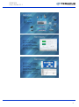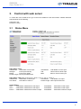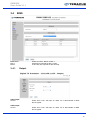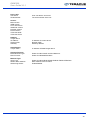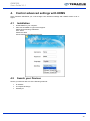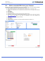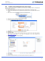
1
DMM 220 User Guide V1.1 DMM-220 User Guide V1.1 Teracue eyevis GmbH Schlossstr. 18 85235 Odelzhausen Germany Tel: Fax: +49 (0)8134-555-10 +49 (0)8134-555-199 [email protected] www.teracue.com 1 DMM 220 User Guide V1.1 2 DMM 220 User Guide V1.1 COPYRIGHT This document may not be reproduced in any form, in whole or in part, without the prior permission of Teracue eyevis GmbH. Copyright © 2014 by Teracue eyevis GmbH, all rights reserved. DISCLAIMER This publication supersedes all previous publications. Information and specification in this documentation is subject to change without notice. Please make sure you have the latest document version. Documents are located at: www.teracue.com/support If you find some points in this document unclear then please let us know, so we can improve this documentation. Thank you! Mail to: [email protected] All information within this document is confidential to Teracue eyevis GmbH costumers and should not be copied or distributed to non Teracue eyevis GmbH customers. TRADEMARKS All Teracue products and all of its components are registered trademarks licensed to Teracue eyevis GmbH. All other logos and trademarks both marked and not, may be trademarks or registered trademarks and therefore property of their respective owners. 3 DMM 220 User Guide V1.1 I. Information about the manual This manual is designed to help administrators and users to install the DMM-220 on their computer. If you received this publication as a PDF, then it's a good idea to print it out for future reference. It is best to use this user guide directly in front of your computer, by doing so you try out everything at once. .!. Important features are marked by this sign. 4 DMM 220 User Guide V1.1 II. 1. Content OVERVIEW ...................................................................................................................................... 6 1.1 1.2 1.3 1.4 1.5 CHARACTERISTICS ..................................................................................................................... 6 MAIN FEATURE .......................................................................................................................... 6 DMM-100 MAIN CHASSIS .......................................................................................................... 6 DMM-100 CU HANDHELD PROGRAMMER UNIT ........................................................................... 6 DMM-220 SERIES PROFESSIONAL MULTI-FORMAT HD/SD IRD AND PROCESSOR MODULE .......... 7 2. CONTROL WITH DISPLAY AND KEYPAD .................................................................................... 7 3. CONTROL WITH WEB SERVER .................................................................................................. 11 3.1 STATUS MENU ......................................................................................................................... 11 3.2 TUNER .................................................................................................................................... 12 3.3 CI ........................................................................................................................................... 13 3.4 BISS ....................................................................................................................................... 14 3.4.1 Output ................................................................................................................................ 14 3.4.2 MUX ................................................................................................................................... 15 3.4.3 IP Out ................................................................................................................................. 15 3.4.4 IP In ................................................................................................................................... 18 3.4.5 Backup ............................................................................................................................... 19 3.4.6 Decoder ............................................................................................................................. 19 3.4.6.1 Audio .......................................................................................................................... 19 3.4.6.2 Video .......................................................................................................................... 20 3.4.6.3 Decoder Play ............................................................................................................. 21 3.4.7 System ............................................................................................................................... 22 3.4.7.1 Device ........................................................................................................................ 22 3.4.7.2 Version ....................................................................................................................... 22 3.4.7.3 Network ...................................................................................................................... 23 3.5 DMM-140 DECODER MODULE ................................................................................................. 24 3.5.1 Status Menu....................................................................................................................... 24 3.5.2 Input Menu ......................................................................................................................... 25 3.5.3 Output Menu ...................................................................................................................... 25 3.5.3.1 ASI Output ................................................................................................................. 25 3.5.3.2 ASI2/SDI .................................................................................................................... 26 3.5.3.3 Decoder Play ............................................................................................................. 26 3.5.3.4 Decoder Config .......................................................................................................... 27 3.5.4 CI ....................................................................................................................................... 28 3.5.5 IP Out ................................................................................................................................. 29 3.5.6 IP In ................................................................................................................................... 31 3.5.7 System ............................................................................................................................... 32 4. CONTROLE ADVANCED SETTINGS WITH HDMS..................................................................... 34 5. TECHNICAL SPECIFICATION ...................................................................................................... 41 5.1 5.2 5.3 5.4 5.5 6. DMM-140 SERIES ................................................................................................................... 41 DMM-150 SERIES ................................................................................................................... 43 DMM-130 TM SERIES ............................................................................................................. 46 DMM-130 MX RE-MULTIPLEXER MODULE ................................................................................ 49 DMM-130 TP.......................................................................................................................... 49 FAQ ................................................................................................................................................ 50 6.1 W HAT IS A “GOOD” INPUT SIGNAL FOR SATELLITE RECEPTION?.................................................... 50 7. STATEMENT OF CONFORMITY DMM-140-SERIES ................................................................... 51 8. STATEMENT OF CONFORMITY DMM-150-SERIES ................................................................... 52 9. STATEMENT OF CONFORMITY DMM-220-SERIES ................................................................... 53 5 DMM 220 User Guide V1.1 1. Overview 1.1 Characteristics DMM-220 is a compact modular digital TV head end that includes professional MPEG-2 and H.264 SD/HD IRD, MPEG-2 and H.264 SD/HD, Re-Multiplexer, DVB Scrambler. Within 19” 4RU chassis, it provides 8 slots for any type of modules with redundant power supply. Also available 19” 1RU chassis for 2 slots with single power supply. With flexible solution and the high density, DMM-220 offers operators the advanced head end architectures in the marketplace for delivering analog and digital broadcast services to their subscribers. Coming with more new modules, DMM-220 is most suitable for future multiple network architectures: streaming and multiplexing of digital content over IP based networks and conversion of digital content for analog networks. 1.2 DVB-S2/S, DVB-S, DVB-C, DVB-T2/T IRD modules with CI 8 Way re-multiplexer module DVB Simulcrypt, BISS-1, BISS-E scrambler module Rich interface with ASI, IP, SDI, YPbPr, CVBS, XLR Web, SNMP Remote Control or handheld programmer unit local control 4RU 19” chassis compact modular design, supporting up to 8 modules with redundant power supply. 1RU 19” chassis compact modular design, supporting up to 2 modules with single power supply Functional module hot-swappable Intelligent cooling system Stand alone function of each module Cost-saving by backward compatible with new modules On site software update through IP 1.3 DMM-100 Main Chassis Standard 19” 4RU chassis with 8 slots for functional modules and 2 slots for power supplies Hot-swappable power supply unit Intelligent cooling system Wall mounted or Rack mounted Backward compatible with new modules Power Supply: AC 100V-260V, 50-60Hz Optional Build-in IP Switch 19” 1RU chassis with 2 slots and single power supply Dimension: L: 40,3 cm, W: 48,3 cm, H: 17,5 cm 1.4 Main Feature DMM-100 CU Handheld Programmer Unit 2 x 20 LCD display screen and 6-key keypad No external power or battery needed Easy and quick on site system configuration without PC Backward compatible with new modules Dimension: L: 17,0 cm, W: 7,5 cm, H: 2,1 cm 6 DMM 220 User Guide V1.1 1.5 DMM-220 Series Professional Multi-format HD/SD IRD and Processor Module 2. Multiple inputs DVB-T2/S2/S/C/T/T2, TS/IP and ASI SD/HD MPEG-2 and H.264 digital video decoding Digital audio decoding and loop through via SDI, HDMI and AES-EBU Multiple analogue and digital outputs, ASI, CVBS, YPbPr, HDMI, SD/HD-SDI, TS/IP Flexible re-multiplexing between 2 x Tuner and TS/IP Inputs 2x DVB-CI slots, multi programs, BISS 1 and BISS E decryption Dynamic PMT detection and automatic updating Support VBI TELETEXT, EBU/ DVB subtitle, closed caption UDP/RTP & Unicast/Multicast SPTS and MPTS over IP I/O Remote control and supervision by SNMP, HTTP WEB PCM audio embedded in SDI output or PCM audio over HDMI PCM output on two AES/EBU output ports On Site software update through HTTP WEB or USB RSSI, received Eb/No & BER monitoring Control with Display and Keypad Main-Menu Sub-Menu Status DVB-S2 QAM Inputs COFDM RSSI Ethernet Description ASI: Display ASI input status TUNER: Display tuner input status IP IN: Display IP input status LNB Frequency: Input LNB frequency Satellite Frequency: Input downstream frequency of satellite Symbol Rate: Input symbol rate of satellite LNB Voltage: Off/13V/18 V LNB 22KHz: 22KHz or Off. DISQEC: Port A/Port B/Port C/Port D/DiSEQC OFF PLS Gold Code: 0~5000 Frequency Offset High: 5000KHz Frequency Offset Low: -5000KHz Constellation: 16/32/64/128/256QAM/64B/256B Frequency: Enter the frequency of the QAM signal in MHz. Symbol Rate: Edit the symbol rate to the proper value in kBaud. Frequency: Input terrestrial frequency. Bandwidth: select bandwidth from 6MHz, 7 MHz and 8 MHz. Tuner Status: Display tuner status Strength Display: Display the strength of tuner signal Stream IP Addr: 1.0.0.1~223.255.255.254 Stream Netmask: 1.0.0.1~223.255.255.254 and 0.0.0.0 Stream Gateway: 1.0.0.1~223.255.255.254 and 224.0.0.0~239.255.255.255 Stream Mac Address: Display MAC address Multicast IP Addr: Enter the IP address of the multicast stream for the transport stream over IP. Multicast UDP Port: Enter the UDP port number of the TS over IP stream. Protocol: UDP/RTP. Output Smoothing: Auto: the bit rate is variable. 7 DMM 220 User Guide V1.1 Disable: the unit let the TS pass by. Fixed Rate: the bit rate is fixed. TS Bit Rate: sets the bit rate of the TS which comes from the TS/IP input. The setting is only valid when the output smoothing is configured as Fixed Rate. Main-Menu Sub-Menu BISS Menu CI Decoder Outputs ASI1/2 SDI Description Biss Mode: Set Biss mode, can select ‘OFF’, ‘Biss E’ or ‘Biss 1’ Biss 1 Setup: Set Biss 1 (password is required) Biss E Setup: Set Biss E (ID number and password are required) Biss Source: Tuner/ASI Input CI Source: MUX TS/Tuner/ASI Input Setup: Select TS CAM Name: Display CAM name of CI Slot1 and Slot2 Status: Show Status Source: CI De-encrypted/TUNER/ASI Input/Mux TS Program: Select programs. Video Video Standard: Select from Auto/1920x1080i 30/1920x1080i 29.97/1920x1080i 25/1280x720p 60/1280x720p 59.97/1280x720p 50/720x480p 59.94/720x480p 60/720x576p 50/720x576p 25/720x480i 29.97/720x576i 25 Screen: Select from Auto, 4:3 Full, 4:3 Letterbox, 16:9 Letterbox or 16:9 Full. DVB subtitle language: Choose DVB Subtitle language. EBU subtitle language: Choose EBU Subtitle language. Subtitle Priority: Select from DVB First or EBU First. Fail Mode: Select from Black Screen, No Sync and Still Picture. VBI Mode: Disable/Enable. VBI option only controls Closed – Caption over CVBS. To activate the CC over CVBS, enable the VBI option. Close Caption: Off/On. Controls both CC on CVBS and SDI. CVBS Sub PAL: select PAL mode, including PALB/D/G/H/I, PAL-N, PAL-N_C and SECAM. CVBS Sub NTSC: select NTSC Mode, including NTSC-M, NTSC-M_J, NTSC-M_443 and PAL-M. Note: the sub-menus VBI Mode, CVBS Sub PAL and CVBS Sub NTSC will only show up when the Closed Caption option is on. Audio Audio Level: 0~99. Audio Mode: select Stereo, Left, Right or Mono for soundtracks. Audio Priority: select the priority of the audio. Mode: select from Manual Selection and First Service. First Service means to select the program no. automatically, normally the first program in the TS. Manual Selection means to select the program manually. ASI1/2 Source: CI De-encrypted/TUNER/ASI Input/Mux TS Embedded Audios: On and Off. Closed Caption Mode: select from SMPTE 708, SMPTE 608, Line 21, and Auto. The mode of closed caption needs to be selected based on the video resolution. SMPTE 708 and SMPTE 608 are more suitable for HD video; SMPTE 608 and Line 21 are for SD. When select Auto, the unit will choose SMPTE 608 for HD video, and Line 21 for SD video. Note: Before doing the setup, be sure to enable the Closed 8 DMM 220 User Guide V1.1 Mux Ethernet Backup Local Setup Trap IP Addr Unit Name Properties Factory Setting Caption switch in the menu Decoder- Video. Mux Switch: On/Off Bit Rate: should be set to a specified value that doesn’t exceed the max physical limit of the output medium. For example, to deliver the multiplexed TS to an 8MHz DVB 256QAM modulator, it should not exceed 55000Kb/s, otherwise overflow occurs. TS ID: 1~65535 Program List: Select program. Output Bit Rate: Display Output bit rate Stream IP Addr: 1.0.0.1~223.255.255.254 Stream Netmask: 1.0.0.1~223.255.255.254 and 0.0.0.0 Stream Gateway: 1.0.0.1~223.255.255.254 and 224.0.0.0~239.255.255.255 Stream Mac address: Display factory-Set Mac addresses Gateway Mac address: Edit Gateway Mac address Multicast IP Addr: Enter the IP address of the Multicast Stream for the transport Stream over IP. Multicast UDP Port: Enter the UDP Port number of the TS over IP stream. Protocol: UDP/RTP TS Pkts Per UDP: 1~7 Time to live: 1~255 Type Of Service: Min Delay/Max Reliability/Max Throughput/Min Monetary Cost/Normal Source: Tuner/ASI input/Mux TS/CI De-encrypted Mode: IPTV/DVB Uni-/Multicast Setup Max Channels: 1~32 Channel 0~31 Switch: On/Off. Enable or disable the channel. Multicast IP Address: 224.0.0.0 ~ 239.255.255.255 *(When using Unicast, the Multicast IP Address should be set as the IP address of the receiving device.) Multicast UDP Port: 1~65535 Target MAC Address: Edit Target MAC Address Program List: Select program Main channel: ASI/Tuner. Backup channel: ASI/Tuner. Main CH Unlock Time: set Main CH Unlock Time, ranging from 0 to 59 seconds. When signal of the main channel remains the disconnected status over this value, the unit will switch to the backup channel automatically. Main CH Recover Time: set Main CH Recover Time, ranging from 0 to 59 seconds. When the signal of the main channel recovers and remains stable over this value, the unit will switch back to the main channel. IP Address: 1.0.0.1~223.255.255.254 Netmask: 1.0.0.1~223.255.255.254 and 0.0.0.0 Gateway: 1.0.0.1~223.255.255.254 and 224.0.0.0~239.255.255.255 MAC Address: Display MAC Address Trap IP Addr Unit Name Main Version Linux OS Version ARM S/W Version Decoder Version FPGA Version TS/IP Out NIOS TS/IP Out FPGA Enter: Yes, Exit: No 9 DMM 220 User Guide V1.1 Optional Function HTTP Login External Board Type: 100M Single In/100M Single Out/No Exist Mux Function: Enable/Disable Filter Function: Select from Disable/Filter/Mux. Modify the username and password for the WEB management. 10 DMM 220 User Guide V1.1 3. Control with web server To control the unit via Web server, type in the unit IP address in the web browser. Default username and password are as following. Username: root Password: 12345 3.1 Status Menu Input Status Tuner Valid Bitrate: valid bitrate of tuner input Strength: Tuner input intensity Eb/N0: Tuner input quality Packet Length: Tuner input Packet size Total Bitrate: C/N: BER: Total bitrate of Tuner input Carrier noise of tuner input Bit error rate of tuner input Input Status TS/IP when IP Extension Board Type is set to TS/IP in Valid Bitrate: valid bitrate of TS/IP input Total Bitrate: Total bitrate of IP input Link Status: Link Status of TS/IP in Packet Length: TS/IP input Packet size Output Status ASI-1 Valid Bitrate: valid bitrate of ASI output ASI-2 Valid Bitrate: valid bitrate of ASI output Remux Valid Bitrate: valid bitrate of Remux output Total Bitrate: Total Bitrate: Total Bitrate: Total bitrate of ASI output Total bitrate of ASI output Total bitrate of Remux output 11 DMM 220 User Guide V1.1 Decoder Status AV Status Video: Status of Decoder output Audio: Status of Decoder output Service CVBS or HDMI Service Type: Service Name from BAT Provider Name: Provider Name from SDT PMT PID: PMT PID Service Name: Service Name from SDT Service ID: Service ID from SDT PCR PID: PCR PID Video Information CVBS or HDMI Video PID: Video PID from PMT Video Standard: Resolution Stream Type: Stream Type MPEG or H264 Aspect Ratio: Aspect Ratio 16:9 or 4:3 Audio Information Audio PID: Audio PID from PMT Audio Sample Rate: Audio Sample Rate 3.2 Audio Format: Audio Format MPEG or AAC Tuner QPSK Setting LNB Freq. (MHz): SatFreq. (MHz): Symbol rate (kBaud): LNB Voltage: LNB 22kHz: DiSEqC: LNB Local Oscillator Frequency Satellite down link frequency Set Symbol rate Select from OFF/13V/18V Select from OFF/22K Select from DiSEqC Off, Port A, Port B, Port C, Port D Configure the satellite settings according to your transponder. Here some helpful hints: - When receiving high band signals (11,8 – 12, 75 GHz) switch LNB 22 kHz on and LNB Freq 10600 - When receiving low band signals (10, 7 – 11, 75 GHz) switch LNB 22 kHz off and LNB Freq 9750 - When receiving vertical signals the LNB Voltage level is 13 Volt - When receiving horizontal signals the LNB Voltage level is 18 Volt 12 DMM 220 User Guide V1.1 - Information about DVB settings at Lyngsat Web site: http://www.lyngsat.com/ - Examples for often used transponders on satellite Astra 19.2.E: Transponder LNB Freq.(MHZ) Symbol Rate (kBaud) 27500 27500 27500 22000 LNB Voltage LNB 22 kHz 10600 10600 10600 10600 Sat Freq. (MHz) 11836 11954 12188 12603 TP 71 (ARD) TP 77 (ZDF) TP 87 (RTL) TP 111 (Sky News International) TP 107 (SAT.1 PRO Sieben) ARD/ZDF HD 18 V 18 V 18 V 18 V on on on on 10600 12545 22000 18 V on 9750 11362 22000 18 V off TP 51 (ARTE) 9750 10744 22000 18 V off TP 104 (TELE 5) 10600 12480 27500 13 V on COFDM Setting Frequency (MHz): Band Width: 3.3 Notes: Local channel frequency select from 6/7/8MHz CI CI-1 or CI2: Source: Program column: Select column: Select the CI slot for descramble the program by CAM modules. Select from Tuner-1, Tuner-2, IP or MUX TS. Show the program name. Select the channels which you want to descramble. Free means this channel can be received without CAM; Bypass means to skip this channel, this program will be still scrambled;. 13 DMM 220 User Guide V1.1 3.4 BISS BISS Mode: Biss 1: Biss E: 3.4.1 Select from OFF, Biss E or Biss 1. Password is required for Biss 1 setup. ID and Key are required for Biss E setup. Output ASI1 Output Source: ASI2 Output Source: Select from Tuner, ASI Input, IP, MUX TS, CI Descramble or BISS De-encrypted. Select from Tuner, ASI Input, IP, MUX TS, CI Descramble or BISS De-encrypted. 14 DMM 220 User Guide V1.1 3.4.2 MUX Output Bit rate: TS input: TS output: 3.4.3 Set output bit rate. Program list from ASI input. User can click ‘Refresh’ button to refresh the list. Select output program. IP Out 15 DMM 220 User Guide V1.1 Source: TS Pkts Per UDP: Protocol: Time to Live: Service type: Stream IP Address: Stream Netmask: Stream Gateway: Stream MAC address: Gateway Mac Address: Mode: TS/IP output signal source, select from: Tuner, ASI, CI Descramble. Set how many TS packages will be encapsulated in one UDP package. The valid range goes from 1 to 7. Select from UDP or RTP. Set the number of the routers over which the TS over IP can be transmitted. The valid range goes from 1 to 255. Select from Normal, Min Monetary Cost, Max Reliability, Max Throughput and MiniDelay. IP address of TS/IP output signal source. Subnet mask of TS/IP output signal source. Gateway of TS/IP output signal source. TS/IP output signal source Mac address. Gateway MAC address. Select from DVB and IPTV output DVB Mode TS which come from the ‘source’ selected in previous step will be packed into IP Stream directly. It requires configuring the following parameters. Multicast/unicast IP: Target UDP port: Target Mac address: Multicast or unicast IP address setting. Multicast UDP port number. Set the Mac address of PC at the receiving end in unicast mode. 16 DMM 220 User Guide V1.1 IPTV Mode TS which come from the ‘source’ selected in previous step will be de-muxed to several single programs, and each program is packed into one IP stream. Channel Number: Channel 0~5 (0~32): Enable: Multicast/unicast IP: Target UDP port: Target Mac Address: TS input: IP output: Select IPTV output channel number ranging from 1~6 (or 1~32). Select IP output channel to be configured. Check this option to enable one channel. Set multicast or unicast IP address. Set multicast UDP port In unicast mode, Mac address of the TS reception device Show program list of signal source. Select the output program of each channel. 17 DMM 220 User Guide V1.1 3.4.4 IP In Multicast IP: Multicast UDP port: Stream IP address: Protocol: Stream Netmask: Smoothing: Stream Gateway: Stream MAC address: Multicast IP address. Set Multicast UDP port number. IP address of TS/IP signal source. Network Protocol including UDP or RTP. Subnet mask of TS/IP signal source. Set smoothing mode, including Auto, Fixed rate, Disable. Gateway of TS/IP signal source. Mac address of TS/IP signal source. 18 DMM 220 User Guide V1.1 3.4.5 Backup Main channel: Backup channel: Main CH Unlock Time: Main CH Recover Time: 3.4.6 3.4.6.1 select main channel from ASI or tuner. select backup channel from ASI or tuner. set Main CH Unlock Time, ranging from 0 to 59 seconds. When signal of the main channel remains the disconnected status over this value, the unit will switch to the backup channel automatically. set Main CH Recover Time, ranging from 0 to 59 seconds. When the signal of the main channel recovers and remains stable over this value, the unit will switch back to the main channel. Decoder Audio Audio Output Audio level: Audio Mode: Audio language: Audio level, ranging from 0-99. Select from Stereo, Left, Right and Mono Audio language SDI Output Embedded Audio: On/Off. 19 DMM 220 User Guide V1.1 3.4.6.2 Video Video Output Video Standard: Screen: DVB subtitle language: EBU subtitle language: Subtitle Priority: Fail Mode: VBI Mode: Close Caption: CVBS Sub PAL: CVBS Sub NTSC: Note: Select from Auto/1920x1080i 30/1920x1080i 29.97/1920x1080i 25/1280x720p 60/1280x720p 59.97/1280x720p 50/720x480p 59.94/720x480p 60/720x480p 60/720x576p 50/720x576p 25/ Select from Auto, 4:3 Full, 4:3 Letterbox, 16:9 Letterbox or 16:9 Full. Choose DVB Subtitle language. Choose EBU Subtitle language. Select from DVB First or EBU First. Select from Black Screen, No Sync and Still Picture. Off/On. VBI option only controls Closed Caption over CVBS. To activate the CC over CVBS, enable the VBI option. Off/On. This switch controls both CC on CVBS and SDI. select PAL mode, including PAL-B/D/G/H/I, PAL-N, PAL-N_C and SECAM. select NTSC Mode, including NTSC-M, NTSC-M_J, NTSC-M_443 and PAL-M. the sub-menus VBI Mode, CVBS Sub PAL and CVBS Sub NTSC will only show up when the Closed Caption option is on. 20 DMM 220 User Guide V1.1 3.4.6.3 Decoder Play Source: Program: Mode Decoder Mode: Select from Tuner, ASI Input, IP, MUX TS, CI Descramble or BISS De-encrypted. Choose the program need to be played Select from Manual Selection and First Service. First Service means to select the program no automatically, normally the first program in the TS. Manual Selection means to select the program manually. 21 DMM 220 User Guide V1.1 3.4.7 System 3.4.7.1 Device Device Information Unit Name: Serial Number: User can edit the unit name. The serial number of the unit. Optional Function External Board Type: Mux Function: Filter Function: Select from No Exist/IP out/IP in/QAM out. Enable/Disable Select from Disable/Filter/Mux. 3.4.7.2 Version 22 DMM 220 User Guide V1.1 3.4.7.3 Network Network Target device Device IP: Net mask: Gateway: MAC Address Alarm Setting Trap IP Addr: IP address of current device. Network mask Gateway address IP address of SNMP target device. NTP NTP Server IP: NTP Interval(s): Time Zone: Edit NTP Server IP. Edit NTP refreshing interval. Select time zone. Time Date: Time: Display current date. Display current time. 23 DMM 220 User Guide V1.1 3.5 DMM-140 Decoder Module 3.5.1 Status Menu Output Status Video: Video status Audio: Audio status Input Status ASI: Packet size: ASI input status ASI input Packet size Total Bitrate: Valid Bitrate: Total bitrate of ASI input Valid bitrate of ASI input Tuner: Packet size: Strength: BER: Tuner input status Tuner input Packet size Tuner input intensity Bit error rate of tuner input Total Bitrate: Valid Bitrate: C/N: Eb/No: Total bitrate of tuner input valid bitrate of tuner input Carrier noise of tuner input Tuner input quality 24 DMM 220 User Guide V1.1 3.5.2 Input Menu LNB Freq. (MHz): SatFreq. (MHz): Symbol rate (KBaud): LNB Voltage: LNB 22KHz: DisEqc: 3.5.3 3.5.3.1 LNB local oscillator frequency Satellite down link frequency Set Symbol rate Select from OFF/13V/18V Select from OFF/22K Select from DisEqc Off, Port A, Port B, Port C, Port D Output Menu ASI Output Source: Packet Size (Byte): Select from Tuner/ASI/CI scramble Bypass/188 25 DMM 220 User Guide V1.1 3.5.3.2 ASI2/SDI ASI2/SDI Output Mode: Select from ASI2/SDI SDI Audio DID: Emb Audios: Select from Group1~4 Select from None/One/Two/One&Two 3.5.3.3 Source: Program: Decoder Play Select from Tuner, ASI, CI Descramble, IP Choose the program need to be played 26 DMM 220 User Guide V1.1 3.5.3.4 Decoder Config Biss Mode: Biss 1 Setup: Biss E Setup: Select from OFF, Biss E or Biss 1. Password is required for Biss 1 setup. ID and Password are required for Biss E setup. Video Output Video Standard: Screen: DVB subtitle language: EBU subtitle language: Subtitle Priority: Fail Mode: VBI Mode: Close Caption: Select from Auto, PAL, NTSC and SECAM. Select from Auto, 4:3 Full, 4:3 Letterbox or 16:9 Full. Choose DVB Subtitle language. Choose EBU Subtitle language. Select from DVB First or EBU First. Select from Black Screen, No Sync and Still Picture. Off/On Off/On Audio Output Audio level: Audio Mode: Audio language: Audio level, ranging from 0-99. Select from Stereo, Left, Right and Mono Audio language 27 DMM 220 User Guide V1.1 3.5.4 CI Source: Program column: Select column: Select from Tuner or ASI. Show the program name. Select the channels which you want to descramble. Free means this channel can be received without CAM; Bypass means to skip this channel, this program will be still scrambled; Slot 1/Slot 2 means to descramble the program by CAM modules in different CI slots. 28 DMM 220 User Guide V1.1 3.5.5 IP Out Source: TS Pkts Per UDP: Protocol: Time to Live: Service type: Stream IP Address: Stream Netmask: Stream Gateway: Stream MAC address: Gateway Mac Address: Mode: TS/IP output signal source, select from: Tuner, ASI, CI Descramble. Set how many TS packages will be encapsulated in one UDP package. The valid range goes from 1 to 7. Select from UDP or RTP. Set the number of the routers over which the TS over IP can be transmitted. The valid range goes from 1 to 255. Select from Normal, Min Monetary Cost, Max Reliability, Max Throughput and Min Delay. IP address of TS/IP output signal source. Subnet mask of TS/IP output signal source. Gateway of TS/IP output signal source. TS/IP output signal source Mac address. Gateway MAC address. Select from DVB and IPTV output 29 DMM 220 User Guide V1.1 DVB Mode TS which come from the ‘source’ selected in previous step will be directly packed into IP Stream. It requires configuration of the following parameters. Multicast/unicast IP: Target UDP port: Target Mac address: Multicast or unicast IP address setting. Multicast UDP port number. Set the Mac address of PC at the receiving end in unicast mode. IPTV Mode TS which comes from the ‘source’ selected in previous step will be de-muxed to several single programs, and each program is packed into one IP stream. Channel Number: Channel 0~5 (0~32): Enable: Multicast/unicast IP: Target UDP port: Target Mac Address: TS input: IP output: Select IPTV output channel number ranging from 1~6 (or 1~32). Select IP output channel to be configured. Check this option to enable one channel. Set multicast or unicast IP address. Set multicast UDP port In unicast Mode, Mac address of the TS reception device Show program list of signal source. Select the output program of each channel. 30 DMM 220 User Guide V1.1 3.5.6 IP In Multicast IP: Multicast UDP port: Stream IP: Protocol: Stream Netmask: Smoothing: Stream Gateway: TS Bit Rate: Stream MAC address: Multicast IP address. Set Multicast UDP port number. IP address of TS/IP signal source. Network protocol including UDP or RTP. Subnet mask of TS/IP signal source. Set smoothing mode, including Auto, Fixed rate, Disable. Gateway of TS/IP signal source. Input Bit rate. Mac address of TS/IP signal source. 31 DMM 220 User Guide V1.1 3.5.7 System 32 DMM 220 User Guide V1.1 Device Info Unit Name: Serial Number: User can edit the unit name. The serial number of the unit. Version Main Version WEB Version Linux OS Version ARM S/W Version Decoder Version FPGA Version TS/IP Out NIOS TS/IP Out FPGA Network Target device IP Address: Subnet mask: Gateway: IP address of current device. Network mask Gateway address Alarm Setting Trap IP Addr: IP address of SNMP target device. Optional Function External Board Type: Filter Function: Select from No Exist/IP out/IP in/QAM out. Select from Disable/Filter/Mux. Machine Type Input Type: Stream MAC Address: Watch Dog Switch: Select from None/DVB-S/DVB-S2/DVB-T/DVB-C/DS3/auto. MAC address of the IP board. Enable/Disable. 33 DMM 220 User Guide V1.1 4. Control advanced settings with HDMS Since Firmware 22PR0034 you could change some advanced settings with HDMS Version 3.03 or higher. 4.1 4.2 Installation Install HDMS on your computer. After start of HDMS a Logon screen appear. Please enter following credentials: User: hdms Password: hdms And choose the right Network Interface. Search your Devices Search your devices with one of the following methods: IP Address A complete IP Range Gateway IP 34 DMM 220 User Guide V1.1 4.3 Open Configuration After successfully discovered devices you can open the configuration with double-click on the Device. You are prompt for the login credentials. Enter the same you are use in the Browser, please see chapter 3. Default: Username: root Password: 12345 After Login you have the Tab for Web Page and Remux. .!. When you use the Remux from HDMS you should not configure anything inside the Remux of the Web Page. 35 DMM 220 User Guide V1.1 4.4 Delete unneeded PID`s from your Channel. In some cases you do not need all the PID from your TV Channel maybe you want to delete unneeded Audio PID`s or HBBT (Private) PID, to do so please do following: a) After changing settings in the Web Page press the refresh Button on the Remux Tab. b) Choose your Channel from the TS Input source and send it to the TS Output with the arrow button. c) Click Apply d) Click Refresh e) Click Edit PSI//SI f) Identify your Program with the Program Number (marked green) g) Identify the PID you want to delete (marked orange) you could use the output with Programs like VLC or TS reader or you take the information’s from some Website like http://www.lyngsat.com. h) Delete all unneeded and save (red marked) i) Click Apply j) Click Refresh k) Add the changed Channel in you TS/IP output like described in Chapter 3.4.1 36 DMM 220 User Guide V1.1 4.5 Create several Output from same Input When you want to make several new Channels from same input, for Example make TV channels with always different Audio PID`s. a) After changing settings in the Web Page press the refresh Button on the Remux Tab. b) Choose your Channel from the TS Input source and send it to the TS Output with the arrow button. c) Right Click on the new TS Output Channel and click Edit Program d) Edit Service name to identify the Program later in TS/IP e) Change the PMT PID to a new unique one. f) g) h) i) j) Click OK Repeat Step b) to f) until you have all wanted channels Click Edit PSI/SI Identify the PID you want to delete (marked orange) you could use the output with Programs like VLC or TS reader or you take the information’s from some Website like http://www.lyngsat.com. Delete all unneeded and save (red marked) k) Click Apply l) Click Refresh m) Add the changed Channel in you TS/IP output like described in Chapter 3.4.1 37 DMM 220 User Guide V1.1 4.6 Prepare a TV Channel with Dynamic PID`s There are TV channels with dynamic PID`s often use in Europe for regional news. To a special time there will be added video or audio PID`s for a short time and the PMT would be updated with the changed PID`s. You could prepare the output that it is switching to the new Video/Audio PID`s. This configuration will always have included all PID`s the current and the following. a) After changing settings in the Web Page press the refresh Button on the Remux Tab. b) Click Advanced Settings c) Choose Tuner and Channel click add and ok d) You have the Test-R now on the TS-Output e) Click PID Remapping and add the PMT PID the current Video and Audio PID`s and the following PID`s, and click OK. 38 DMM 220 User Guide V1.1 f) g) h) i) j) Click Apply Go to the Web Page Tab open the TS/IP Uni/Multicast Setup Add your Dynamic Channel to the TS/IP output Add also here all PID`s you have entered by the PID Remapping Click apply and close .!. configure the Dynamic Channel at last, because with click apply you add the Output PID`s to all channels. 39 DMM 220 User Guide V1.1 4.7 Prepare a TV Channel with Dynamic PID`s for recording. There are TV channels with dynamic PID`s often use in Europe for regional news. To a special time there will be added video or audio PID`s for a short time and the PMT would be updated with the changed PID`s. This configuration is special for recording. As opposed to chapter 4.7 it do not have Ghost PID`s but would have only Signal in case of the changed PID`s. As result you have 2 different non dynamic Channels. a) After changing settings in the Web Page press the refresh Button on the Remux Tab. b) Choose your Channel from the TS Input source and send it to the TS Output with the arrow button c) Right Click on the new TS Output Channel and click Edit Program d) Edit Service name to identify the Program later in TS/IP e) Change the PMT PID to a new unique one. f) Click OK g) Click Apply h) The Remuxer Tab is reading the TS Input information only once as long they haven`t changed. So after the Channel have switched to the new PID`s you have to cause the Tuner to tune again. You could do so either with unplug the RF Input Cable or change the Tuner Input setting to a different one, e.g. LNB LO Frequency from 9750 to 975 for 10 seconds and back. i) Repeat Step b) to f) j) Add the changed Channel in you TS/IP output like described in Chapter 3.4.1 4.8 Restrictions and useful hints. a) When using the Remuxer on HDMS do not use the Remuxer from Web Page. b) While configuring the Remuxer it is very helpful to set no output to remuxer until the remuxer configuration is finished. c) When using Dynamic PID`s configuration like in chapter 4.7 you could not delete unneeded PID`s,like additional Audio or Teletext. d) When using Dynamic PID`s configuration like in chapter 4.7 you could only use one Tuner. e) Configure the Dynamic Channel at last, because with click apply on the TS/IP Web Page you add the Output PID`s to all channels. 40 DMM 220 User Guide V1.1 5. 5.1 Technical Specification DMM-140 Series Tuner Input DVB-S/S2 Tuner Input Connector Type Input Frequency Range Input Level Symbol Rates Roll-off Factor FEC Code Rate LNB Polarization LNB Band Switching Tone DVB-S Tuner Input Connector Type Input Frequency Range Input Level Symbol Rates Roll-off Factor Puncture Rates LNB Polarization LNB Band Switching Tone DVB-C Tuner Input Connector Type Input Frequency Range Symbol Rates Constellation Input Level Bandwidth Input Return Loss DVB-T Tuner Input Connector Type Input Frequency Range Input Level Constellation Carrier bandwidth FTT Mode Guard Interval FEC Code Rate ASI Input Connector Standard Input Bit Rates Package Length TS over IP Connector Type Useful bit rate Protocol 1 x F type female 75Ω for Input, 1 x F type female 75Ω for loop through output 950 ~ 2150MHz -25 ~ -65dBm DVB-S QPSK: 5 ~ 45MS/s; DVB-S2 8PSK 10~31MS/s DVB-S QPSK: 0.35; DVB-S2 8PSK: 0.35, 0.25, 0.2 DVB-S2 8PSK: 2/3, 3/4, 3/5, 5/6, 8/9, 9/10 DVB-S QPSK: 1/2, 2/3, 3/4, 5/6, 6/7, 7/8 0, 13V, 18V selectable 0/22kHz selectable 1 x F type female 75Ω for Input, 1 x F type female 75Ω for loop through output 950 ~ 2150MHz -25 ~ -65dBm 2 ~ 45MS/s 0.35 1/2, 2/3, 3/4, 5/6, 7/8 0, 13V, 18V selectable 0/22kHz selectable 1 x F type female 75Ω for Input, 1 x F type female 75Ω for loop through output 48 ~ 860MHz 1 ~ 7MS/s (ITU J.83 Annex A) 64/128/256 QAM -15 ~ 15dBmV 6/7/8MHz 7dB (typ.) 1 x F type female 75Ω for Input, 1 x F type female 75Ω for loop through output 174 ~ 230MHz (VHF); 470 ~ 860MHz (UHF) -20 ~ -70dBm QPSK, 16-QAM, 64-QAM 6/7/8 MHz 2K/8K 1/4, 1/8, 1/16, 1/32 1/2, 2/3, 3/4, 5/6, 7/8 1 x BNC Female, 75Ω DVB-ASI, EN50083-9 ≤ 100Mb/s 188 or 204 Bytes 1 x RJ45, 10/100M for TS/IP 70Mb/s for 10/100M UDP / RTP, Multicast / Unicast, IGMPv2, ARP 41 DMM 220 User Guide V1.1 TS Processing TS Input Management TS Output Management Service and PID management PSI/SI Descrambler Common Interface ASI Output Connector Type Standard Output Bit Rates Digital Video Processing Video Standard SDI Video Resolution Video Bit Rate SD-SDI Output Connector Type Serial Interface Level Audio Embedded Digital Audio Processing Number of Outputs Analog Video Output CVBS Connector Video Standard Analog Audio Output Connector Type Number of Outputs Control & Monitoring Connector Type Remote Control Local Control Software Upgrade Remux and demux between Tuner, ASI and TS/IP Inputs Remux and demux for 2 mirror ASI outputs Remux, filtering and remapping PSI/SI table regeneration, NIT and SDT edition, LCN Edition and Re-generation DVB Common Scrambling Algorithm (CSA) Double PCMCIA slots, compatible with major CA CAMs in the market 2 x BNC Female, 75Ω (one connector is shared with SDI output) DVB-ASI, EN50083-9 ≤ 99Mb/s MPEG-2(MP@ML) 576i x 25, 480i x 29.97 < 80Mb/s 1 x BNC Female, 75Ω (share with one of the two ASI outputs) SMPTE 259M, 270 Mb/s (10bit) 800mV p-p Yes 1 pair of stereo audio output (1 Audio PID is decoded) 1 x 2.5mm phone jack (with phone jack to RCA adaptor) NTSC, PAL, and SECAM 1 x 2.5mm phone jack for CVBS and stereo audio 1 pair of stereo audio 1 x RJ45, 10/100M, for equipment IP Control SNMP, HTTP Web, Proprietary HDMS Network System Management Software Handheld Programmer Unit FTP loader 42 DMM 220 User Guide V1.1 5.2 DMM-150 Series Tuner Input DVB-S/S2 Tuner Input Connector Type Input Frequency Range Input Level Symbol Rate Rolling-off Factor Punctured Rates LNB Polarization LNB Band Switching Tone DiSEqC DVB-C Tuner Input Connector Type Input frequency Input level Symbol rate Constellation Bandwidth Input return loss DVB-T/T2 Tuner Input Connector Type Input frequency Input level Constellation Bandwidth FFT mode Guard interval FEC code rate Input return ASI Input Connector Type Standard Input Bit Rates Package Length TS Processing TS over IP Connector Type Useful bit rate Protocol 1 x F type female 75Ω for Input, 1 x F type female 75Ω for loop through output 950 ~ 2150MHz -25 ~ -65dBm 5 ~ 45MS/s for QPSK 10 ~ 31MS/s for 8PSK DVB-S QPSK: 0.35 DVB-S2 8PSK: 0.35, 0.25, 0.2 DVB-S QPSK: 1/2, 3/5, 2/3, 3/4, 4/5, 5/6, 8/9, 8/10 DVB-S2 8PSK: 3/5, 2/3, 3/4, 5/6, 8/9, 9/10 0, 13V, 18V selectable 0/22kHz selectable DiSEqC 1.0 1 x F type female 75Ω for Input, 1 x F type female 75Ω for loop through output 48 ~ 860MHz 45 ~ 75dBuV 1 ~ 7MS/s (ITU J.83 Annex A) 64/128/256QAM 6/7/8MHz 7dB (typ.) 1 x F type female 75Ω for Input, 1 x F type female 75Ω for loop through output 104 ~ 862MHz (VHF/UHF) -20 ~ -70dBm (Quasi Error Free, QEF) DVB-T: QPSK/16-QAM/64-QAM DVB-T2: QPSK, 16QAM, 64QAM, 256QAM 6MHz/7MHz/8MHz DVB-T: 2K/8K DVB-T2: 1K, 2K, 4K, 8K, 16K, 32K DVB-T: 1/4, 1/8, 1/16, 1/32 DVB-T2: 1/4, 5/32, 1/8, 5/64, 1/16, 1/32, 1/64, 1/128 DVB-T: 1/2, 2/3, 3/4, 5/6, 7/8 DVB-T2: 1/2, 3/5, 2/3, 3/4, 4/5, 5/6 7dB (typ.) 2 x BNC Female, 75Ω DVB-ASI, EN50083-9 ≤ 100Mb/s 188 or 204 Bytes Re-multiplexing of 2 ASI Inputs 1 x RJ45, 10/100M for TS/IP 70Mb/s for 10/100M UDP / RTP, Multicast / Unicast, IGMPv2, ARP 43 DMM 220 User Guide V1.1 TS Processing TS Input Management TS Output Management Service and PID management PSI/SI Descrambler BISS Mode Common Interface ASI Output Connector Type Standard TS Processing HDMI Output Standard HDMI Video Resolution Embedded Digital Video Processing Video Standard SDI Video Resolution Video Bit Rate SD-SDI Output Connector Type Serial Interface Level HD-SDI Output Connector Type Serial Interface Level Digital Audio Processing Number of Outputs Analog Video Output YPbPr Connector CVBS Connector Video Standard YPbPr Resolution Signal Level Frequency Response Chroma-Luma Delay Field Time Distortion Line Time Distortion Short Time distortion Differential Gain Differential Phase Signal to Noise Ratio Analog Audio Output Connector type Output mode Number of Outputs Remux and demux between Tuner, ASI and TS/IP Inputs Remux and demux for 2 independent ASI outputs Remux, filtering and remapping PSI/SI table regeneration, NIT and SDT edition, LCN Edition and regeneration DVB Common Scrambling Algorithm (CSA) BISS-1, BISS-E Double PCMCIA slots, compatible with major CA CAMs in the market 2 x BNC Female, 75Ω DVB-ASI, EN50083-9 2 Independent TS Re-multiplexing from tuner, TS/IP and 2 ASI inputs 1x HDMI 1.3 interface (partial) 1080i x 30, 1080i x 29.97, 1080i x 25, 720p x 60, 720p x 59.94, 720p x 50, 480p x 60, 576p x 50, 576i x 25, 480i x 29.97 Digital Audio Loop Through MPEG-2(MP@ ML for SD, MP@HL for HD) MPEG 4/H.264 Part 10 (MP@L3 for SD, [email protected] for HD) 1080i x 30, 1080i x 29.97, 1080i x 25, 720p x 60 720p x 59.94, 720p x 50, 576i x 25, 480i x 29.97 < 80Mb/s 2 x SD-SDI outputs in mirror, BNC Female, 75Ω SMPTE 259M, 270 Mb/s (10bit) 800mV p-p 2 HD-SDI outputs in mirror, BNC Female, 75Ω SMPTE 292M, 1.485 Gbit/s (10bit) 800mV p-p 2 pairs of audio outputs (2 Audio PIDs are decoded) 1 x 2.5mm phone jack, 75Ω (phone jack to RCA adaptor) 1 x 2.5mm phone jack, 75Ω (phone jack to RCA adaptor) NTSC, PAL, and SECAM 1080i x 30, 1080i x 29.97, 1080i x 25, 720p x 60, 720p x 59.94, 720p x 50, 480p x 60, 576p x 50, 576i x 25, 480i x 29.97 I.0 Vp-p±5% < ±I dB at 5.5 MHz < ±30 ns < 2% < 1% < 2% < 4% < 2° > 55 dB (luminance weighted) 1 x 2.5mm phone jack, 75Ω (phone jack to RCA adaptor) Left, Right, Dual Mono, Stereo 2 pairs of audio outputs (2 Audio PIDs are decoded). 44 DMM 220 User Guide V1.1 Baseband Data Output Subtitle VBI Closed Caption Redundancy Redundancy Port Switching Condition Switching Mode Control & Monitoring Connector Type Remote Control Local Control Equipment Upgrade DVB/EBU Teletext, WSS, VFD, VPS EIA 608, EIA 708, EIA 608-to-708 between Tuner, 2 x ASI inputs and TS/IP TS Sync Loss Main, Spare 1×RJ45, 10/100M, for equipment IP Control SNMP, HTTP Web, Proprietary HDMS Network System Management Software Handheld Programmer Unit FTP loader 45 DMM 220 User Guide V1.1 5.3 DMM-130 TM Series Tuner Input DVB-S/S2 Tuner Input Connector Type Input Frequency Range Input Level Symbol Rates Roll-off Factor Puncture Rates LNB Polarization LNB Band Switching Tone DVB-S Tuner Input Connector Type Input Frequency Range Input Level Symbol Rates Roll-off Factor Puncture Rates LNB Polarization LNB Band Switching Tone DVB-C Tuner Input Connector Type Input Frequency Range Symbol Rates Constellation Input Level Bandwidth Input Return Loss DVB-T Tuner Input Connector Type Input Frequency Range Input Level Constellation Carrier bandwidth FTT Mode Guard Interval FEC Code Rate ASI Input Connector Standard Input Bit Rates Package Length TS Processing TS Input Management Service and PID management PSI/SI ASI Output Connector Type Standard 1 x F type female 75Ω for Input, 1 x F type female 75Ω for loop through output 950 ~ 2150MHz -25 ~ -65dBm DVB-S QPSK: 5~45MS/s; DVB-S QPSK: 0.35; DVB-S2 8PSK: 0.35, 0.25, 0.2 DVB-S2 8PSK: 2/3, 3/4, 3/5, 5/6, 8/9, 9/10 DVB-S QPSK: 1/2, 2/3, 3/4, 5/6, 6/7, 7/8 0, 13V, 18V selectable 0/22kHz selectable 1 x F type female 75Ω for Input, 1 x F type female 75Ω for loop through output 950 ~ 2150MHz -25 ~ -65dBm 2 ~ 45MS/s 0.35 1/2, 2/3, 3/4, 5/6, 7/8 0, 13V, 18V selectable 0/22kHz selectable 1 x F type female 75Ω for Input, 1 x F type female 75Ω for loop through output 48 ~ 860MHz 1 ~ 7MS/s (ITU J.83 Annex A) 64/128/256 QAM -15 ~ 15dBmV 6/7/8MHz 7dB (typ.) 1 x F type female 75Ω for Input, 1 x F type female 75Ω for loop through output 174 ~ 230MHz (VHF); 470 ~ 860MHz (UHF) -20 ~ -70dBm QPSK, 16-QAM, 64-QAM 6/7/8 MHz 2K/8K 1/4, 1/8, 1/16, 1/32 1/2, 2/3, 3/4, 5/6, 7/8 1 x BNC Female, 75Ω DVB-ASI, EN50083-9 ≤ 100Mb/s 188 or 204 Bytes Remux and demux between Tuner and ASI Inputs Remux, filtering and remapping PSI/SI table regeneration, NIT and SDT edition, LCN Edition and regeneration 1 x BNC Female, 75Ω DVB-ASI, EN50083-9 46 DMM 220 User Guide V1.1 TS Processing 2 mirror TS Re-multiplexing from Tuner and ASI inputs 47 DMM 220 User Guide V1.1 DVB-C Re-Modulation Constellation Symbol Rate I/Q Amplitude Error I/Q Phase Error Phase jitter MER DVB-T Re-Modulation Constellation Bandwidth FFT Mode Guard Interval Code Rate RF Output Connector Type Output Frequency Range Output Level MER Spurious Rejection Output Return Loss Control & Monitoring Connector Type Remote Control Local Control Software Upgrade J.83 Annex A: 16/32/64/128/256QAM; J.83 Annex B: 64/256QAM 3 ~ 7.2MS/s < 0.3% < 0.3° < 0.5°RMS > 35dB QPSK/16QAM/64QAM 5/6/7/8MHz 2K 1/4, 1/8, 1/16, 1/32 1/2, 2/3, 3/4, 5/6, 7/8 F type female, 75Ω 48 ~ 860MHz agile, step by 10 kHz 97 ~ 110dBμV, step by 1dBμV > 36.5dB 55dB (typ.) 12dB (typ.) 1 x RJ45, 10/100M, for equipment IP Control SNMP, HTTP Web, Proprietary HDMS Network System Management Software Handheld Programmer Unit FTP loader 48 DMM 220 User Guide V1.1 5.4 DMM-130 MX Re-multiplexer Module ASI Input Connector Type Input bit rate Data transmission mode Packet Length ASI Output Connector Type Output bit rate Data transmission mode Packet Length Signal Level Control & Monitoring Connector Type Remote Control Local Control Software Upgrade 5.5 8 x BNC Female, 75Ω ≤ 100Mb/s BYTE or BURST mode auto-detection 188 /204 bytes, auto-detection 2 x BNC Female, 75Ω ≤ 99Mb/s Byte 188 or 204 Bytes 800mVpp±10% 1×RJ45, 10/100M, for equipment IP Control SNMP, Proprietary HDMS network Management Software Handheld Programmer Unit FTP loader DMM-130 TP ASI Input Connector Type Input Bit Rate Packet Mode TS Processing Scrambler Type Scrambler Mode EMM/ECM Number EMM/ECM Port ASI Output Connector Type Output Bit Rate Packet Mode Control & Monitoring Connector Type Remote Control Local Control Software Upgrade 2 x BNC Female, 75Ω ≤ 60Mb/s 188/204 Bytes DVB Common Scrambling BISS-1, BISS-E and Simulcrypt 48 Max RJ-45, UDP/TCP 2 x BNC Female, 75Ω, ISO13818-1 1-54Mbps adjustable 188/204 Bytes 1×RJ45, 10/100M, for equipment IP Control SNMP, HTTP Web Handheld Programmer Unit FTP Loader 49 DMM 220 User Guide V1.1 6. FAQ 6.1 What is a “good” input signal for satellite reception? Strength: the range is -25 ~ -65dBm, the more large value is better within this range, like: -30dBm is better than -25dBm C/N and Eb/N0: the more large value is better, C/N reference value: 9.5dB, Eb/N0 reference value: 6.4dB, could receive a good signal BER: the lower value is better, BER reference value 0.0E-8 and 0.0E-9, could receive a good signal 50 DMM 220 User Guide V1.1 7. Statement of Conformity DMM-140-Series state that our products, where they bear the CE marking illustrated above, are in conformity with the following standards: EN 50083-2:2001 EN 61000-3-2:2006 EN 61000-3-3:2008 Electromagnetic compatibility for equipment – Cabled distribution systems for television and sound signals. Electromagnetic compatibility Limits – Limits for harmonic current emissions (equipment input current <= 16 A per phase). Electromagnetic compatibility Limits – Limitation of voltage changes, voltage fluctuations and flicker in public low-voltage supply systems, for equipment with rated current <= 16 A per phase and not subject to conditional connection. This regards to the following Teracue products: DMM-100-FR DMM-140-S2 DMM-140-C DMM-140-T Designed, developed and manufactured to conform with the: - Directive EMC 2004/108/EC Electromagnetic Compatibility 51 DMM 220 User Guide V1.1 8. Statement of Conformity DMM-150-Series state that our products, where they bear the CE marking illustrated above, are in conformity with the following standards: EN 50083-2:2006 EN 61000-3-2:2006 + A1:2009 + A2:2009 EN 61000-3-3:2008 Electromagnetic compatibility for equipment – Cabled distribution systems for television and sound signals. Electromagnetic compatibility Limits – Limits for harmonic current emissions (equipment input current <= 16 A per phase). Electromagnetic compatibility Limits – Limitation of voltage changes, voltage fluctuations and flicker in public low-voltage supply systems, for equipment with rated current <= 16 A per phase and not subject to conditional connection. This regards to the following Teracue products: DMM-100-FR, DMM-100-FR-1RU DMM-150-S2, DMM-150-C, DMM-150-T, DMM-150-T2 Designed, developed and manufactured to conform with the: - Directive EMC 2004/108/EC Electromagnetic Compatibility 52 DMM 220 User Guide V1.1 9. Statement of Conformity DMM-220-Series state that our products, where they bear the CE marking illustrated above, are in conformity with the following standards: EN 50083-2:2006 EN 61000-3-2:2006 + A1:2009 + A2:2009 EN 61000-3-3:2008 Electromagnetic compatibility for equipment – Cabled distribution systems for television and sound signals. Electromagnetic compatibility Limits – Limits for harmonic current emissions (equipment input current <= 16 A per phase). Electromagnetic compatibility Limits – Limitation of voltage changes, voltage fluctuations and flicker in public low-voltage supply systems, for equipment with rated current <= 16 A per phase and not subject to conditional connection. This regards to the following Teracue products: DMM-100-FR, DMM-100-FR-1RU DMM-220-S2, DMM-220-T/T2/C Designed, developed and manufactured to conform with the: - Directive EMC 2004/108/EC Electromagnetic Compatibility 53