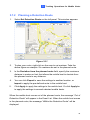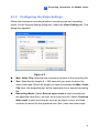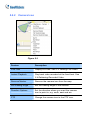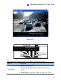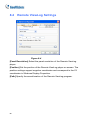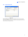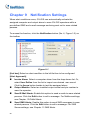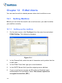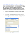
1
GV-GIS User’s Manual V3.0 © 2011 GeoVision, Inc. All rights reserved. Under the copyright laws, this manual may not be copied, in whole or in part, without the written consent of GeoVision. Every effort has been made to ensure that the information in this manual is accurate. GeoVision, Inc. makes no expressed or implied warranty of any kind and assumes no responsibility for errors or omissions. No liability is assumed for incidental or consequential damages arising from the use of the information or products contained herein. Features and specifications are subject to change without notice. GeoVision, Inc. 9F, No. 246, Sec. 1, Neihu Rd., Neihu District, Taipei, Taiwan Tel: +886-2-8797-8377 Fax: +886-2-8797-8335 http://www.geovision.com.tw Trademarks used in this manual: GeoVision, the GeoVision logo and GV series products are trademarks of GeoVision, Inc. Windows and Windows XP are registered trademarks of Microsoft Corporation. July 2011 Contents Naming and Definition............................................................................... v Important Notice ........................................................................................ v Chapter 1 Introduction............................................................................1 1.1 Features ......................................................................................2 1.2 System Requirements................................................................. 3 1.3 Overview of GV-GIS....................................................................6 1.3.1 Main Screen .....................................................................6 1.3.2 Toolbar ............................................................................. 7 1.3.3 Event List .........................................................................9 Chapter 2 2.1 2.2 Getting Started.....................................................................10 Installing the GV-GIS................................................................. 10 Creating Host Accounts............................................................. 13 2.2.1 Creating a Mobile Host................................................... 13 2.2.2 Creating a Fixed Host .................................................... 14 2.3 Connecting Hosts to the GV-GIS .............................................. 16 2.3.1 Connecting a Mobile Host .............................................. 16 2.3.2 Connecting a Fixed Host................................................ 17 2.4 Advanced Settings for Mobile Host ........................................... 18 2.4.1 Configuring the Subscribing Settings ............................. 18 Chapter 3 Tracking Operations for Mobile Hosts............................... 19 3.1 Starting the Tracking Services................................................... 19 3.2 Tracking Features .....................................................................19 3.3 Viewing Live Video ....................................................................22 3.3.1 Colorful Mode................................................................. 23 3.4 Playing Back GPS Tracks .........................................................24 3.4.1 Setting Playback Default Time Range ........................... 26 3.4.2 Showing the Time when a Host Passed by a Point ....... 27 3.4.3 Showing GPS Tracks while Retrieving the Recordings . 27 3.5 Remote ViewLog.......................................................................28 i 3.6 Tracking Multiple Hosts .............................................................29 3.6.1 Tracking Locations ......................................................... 29 3.6.2 Tracking Addresses........................................................ 30 3.7 Detecting Detours .....................................................................31 3.7.1 Defining a Detection Area .............................................. 31 3.7.2 Planning a Detection Route ........................................... 33 3.8 Detecting Idle Speed .................................................................34 3.9 Detecting Over Speed ............................................................... 36 3.10 Viewing a List of Detection Settings.......................................... 38 3.11 Searching for Places and Devices ............................................ 39 Chapter 4 4.1 Recording Operations for Mobile Hosts............................ 43 Configuring the Basics ..............................................................43 4.1.1 Configuring the Storage Group ...................................... 43 4.1.2 Configuring the Video Settings....................................... 45 4.1.3 Configuring the Recycle Settings ................................... 46 4.1.3 Configuring the Recycle Settings ................................... 46 4.2 Recording Manually .................................................................. 47 4.3 Recording by Events .................................................................50 4.4 Recording upon Input Trigger.................................................... 52 Chapter 5 Monitoring Operations for Fixed Hosts ............................. 55 5.1 Starting the Monitoring Services ............................................... 55 5.2 Monitoring Features .................................................................. 56 5.2.1 Fixed Host Icon .............................................................. 56 5.2.2 Camera Icon................................................................... 58 5.2.3 Output Icon.....................................................................59 5.3 Detecting Motion and Input-Triggered Events........................... 60 5.4 Retrieving Recorded Videos ..................................................... 62 5.4.1 Instant Playback.............................................................62 5.4.2 Remote ViewLog............................................................ 65 Chapter 6 6.1 ii Advanced Operations ......................................................... 66 Creating an E-Map ....................................................................66 6.1.1 Configuring E-Map Icon Settings ................................... 67 6.2 Adding a Place .......................................................................... 68 6.3 Saving a View ...........................................................................70 6.4 Getting Driving Directions ......................................................... 71 6.5 Self-Defining Event Colors ........................................................ 73 6.6 Showing Host Position on an Alarm Event................................ 74 6.7 Applying Longitude and Latitude Positions on Fixed Hosts ...... 75 6.8 Monitoring GV-I/O Boxes .......................................................... 77 Chapter 7 Event Log Browser.............................................................. 78 7.1 Opening the Event Log ............................................................. 80 7.2 Filtering the Event Log ..............................................................81 7.3 Backing up the Event Log ......................................................... 82 7.4 Printing the Event Log............................................................... 84 Chapter 8 System Configurations ....................................................... 85 8.1 Layout Settings ......................................................................... 85 8.2 Network Settings .......................................................................86 8.3 Event Log Settings ....................................................................87 8.4 Remote ViewLog Settings......................................................... 88 8.5 Alert Intervals ............................................................................ 89 Chapter 9 Notification Settings............................................................ 90 Chapter 10 Output Alerts ........................................................................ 92 10.1 Adding Output Devices ............................................................. 92 10.2 Forcing Outputs of GV-GIS ....................................................... 94 10.3 Forcing Outputs of a Host ......................................................... 94 Chapter 11 SMS Alerts ............................................................................95 11.1 Setting SMS Server................................................................... 95 11.2 Connecting to SMS Server........................................................ 97 11.3 Sending SMS ............................................................................97 11.4 Inserting Text to Alert Messages ............................................... 98 iii Chapter 12 E-Mail Alerts .......................................................................100 12.1 Setting Mailbox........................................................................ 100 12.1.1 Setting up the mailbox.................................................. 100 12.1.2 Sending a Test E-Mail .................................................. 101 12.2 Sending E-Mail........................................................................102 Chapter 13 Failover Support ................................................................103 Chapter 14 Remote Viewing Using a Web Browser ........................... 105 14.1 Creating Web Accounts........................................................... 105 14.2 Accessing the Web Interface .................................................. 107 14.3 Accessing Monitoring Features............................................... 109 14.3.1 Host Icon ......................................................................109 14.3.2 Input and Output Icons................................................. 110 14.4 Viewing Live Video from a Web Browser ................................ 111 14.5 Retrieving Recorded Videos from a Web Browser.................. 113 14.6 Accessing the Event Log from a Web Browser....................... 115 14.7 Getting Driving Directions from a Web Browser...................... 116 Appendix ............................................................................................. 117 A. Specifications .......................................................................... 117 B. Upgrading the GV-GIS Dongle................................................ 118 C. Shortcut Keys..........................................................................120 D. GPS Settings on GV-System .................................................. 121 E. D.1 Setting the GPS Receiver ............................................ 121 D.2 Recording GPS Locations of GV-System .................... 123 D.3 Recording GPS Locations of the IP Device ................. 124 D.4 Sending GPS Data to the GV-GIS ............................... 125 Modifying Port Number for running GV-GIS on the same computer with GV-System .............................................................. 129 iv Naming and Definition GV-System GeoVision Analog and Digital Video Recording Software. The GV-System also refers to Mutlicam System, GV-NVR System and GV-Hybrid DVR System at the same time. Important Notice Google Maps or Microsoft Virtual Earth is required in implementing the GV-GIS. Users may need to purchase the API Premium Key. Since Google Maps and Microsoft Virtual Earth are third-party applications, users are responsible for following their terms and conditions. v 1 Chapter 1 Introduction Introduction The GV-GIS is a GIS (Geographic Information System) based central management system for GeoVision devices. The vehicle tracking and location verification remotely from the GV-GIS is made possible by the GPS receiver installed in GV-Video Server and GV-Compact DVR to constantly obtain the GPS data (vehicle coordinates and speed) from the satellite, and through mobile internet connection (e.g. UMTS, EDGE, GPRS, GSM, etc) to transmit the GPS data to the GV-GIS. Besides real-time vehicle tracking, you can also monitor the location of cameras and the status of I/O devices from the DVR devices, without GPS functions. Figure 1-1 1 1.1 • • • • • • • • • • • • • Features GIS central management system 500 vehicles tracking at one time Real-time vehicle GPS coordinates Real-time vehicle video image Google Maps, Microsoft Virtual Earth and user-defined maps support GPS Tracks playback Detour Detection Idle Speed Detection Over Speed Detection E-Map Support Motion and Input-triggered alert for fixed hosts Customized landmark (interested points) setting Integration with GV-I/O Box, GV-Video Server, GV-Compact DVR, GV-IP Camera, GV-System and GV-NVR • 2 GIS Web Interface for remote monitoring and tracking 1 1.2 1. Introduction System Requirements The minimum system requirements to run the GV-GIS: Standard Version 10 Mobile-Host Map Views OS 10 Mobile-Host Map Views with up to 10 Megapixel Live Views 32-bit Windows XP / Vista / 7/ Server 2008 64-bit Windows 7/ Server 2008 CPU Memory Hard Disk Pentium 4, 3.0 GHz with HT 2 x 512 MB Dual Channels Core 2 Quad 8300, 2.5GHz 2 x 1 GB Dual Channels The hard disk space required to install GV-GIS (Standard Version) must be at least 1 GB. VGA NVIDIA GeForce 8600 GT / ATI Radeon X1650 DirectX 9.0c Browser Internet Explorer 7.x Software .Net Framework 3.5 Hardware Internal or External GV-GIS Dongle Note: DirectX and .Net Framework can be found in the Software DVD. 3 Advanced Version (Up to 500 Mobile Hosts) 16 Mobile-Host Map Views OS 32-bit 64-bit CPU Memory Hard Disk 16 Mobile-Host Map Views with up to 16 Megapixel Live Views Windows XP / Vista / 7 / Server 2008 Windows 7/ Server 2008 Pentium 4, 3.0 GHz with HT Core i5-750, 2.67GHZ 2 x 1 GB Dual Channels The hard disk space required to install GV-GIS (Advanced Version) must be at least 1 GB. VGA NVIDIA GeForce 8600 GT / ATI Radeon X1650 DirectX 9.0c Browser Internet Explorer 7.x Software .Net Framework 3.5 Hardware External or Internal GV-GIS Dongle Note: DirectX and .Net Framework can be found in the Software DVD. Note: The minimum system requirements are collected by using the GV-IPCam 1.3M for test, and may vary based on connected IP device models. Dongle Options GIS GIS + AVP Combinations GIS + VSM GIS + VSM + AVP NVR + LPR + GIS 4 1 2. Introduction A GV-GIS dongle is required for the GV-GIS software to work. y The primary USB dongle provides the options of 1, 3, 5, and 10 vehicle connections. After first 10 vehicle connections, every increment is 5 connections with the limit of 500 connections in total. Inform your sales representative the required number of vehicle connections so the dongle can be delivered upon your requirements. Otherwise, you can upgrade your primary dongle later by following the instructions in Upgrading the GV-GIS Dongle, Appendix B. y The GV-GIS dongles come in two options, External USB Dongle and Internal USB Dongle. Note: For the Defog and Stabilizer functions on Live View, the GV-GIS dongle with AVP function is required. 5 1.3 Overview of GV-GIS Get yourself familiar with the Main Screen, Toolbar and Event List, as it will help you when you read further in the following sections. 1.3.1 Main Screen Microsoft Virtual Earth is used as Map API (Application Program Interface) in this example. Figure 1-2 6 1 No. Name 1 Host List 2 Toolbar 3 Navigation Controls 4 Map 5 Views 6 Overview Map Introduction Description Include these types of folders: Mobile Host List, Fixed Host List, Expended Markers, and New Map. See 1.3.2 ToolBar. Use these to pan, return to the last result, and zoom. This area displays the tracking map, E-Map and query results. Click these to display different views, including aerial images and street level imagery. This view shows the location of current map view. Displays the manual recording status of Mobile Hosts and the cameras. To display Monitor List or Map 7 Manual Record Event list, click View on the GIS window and select List from the menu. For details, see 5.3 Detecting Motion and Input-triggered Events and 3.10 Viewing a List of Detection Settings respectively. Indicate the connected mobile hosts. Take the picture 8 Tracking Host Indicator for example. Three (3) mobile hosts are connecting to the GV-GIS while GV-GIS supports the maximum of 50 mobile hosts. 9 Event List See Event List later. 1.3.2 Toolbar Figure 1-3 7 No. Name Description 1 Start/Stop Service Start or stop the GV-GIS services. 2 Start/Stop Web Service 3 4 5 6 7 8 9 10 11 12 13 Enable or disable the access to GV-GIS’s Web interface. Configure the system. See Chapter 8 System System Configuration Configurations. Configure host accounts. See 2.2 Creating Account Host Accounts. Configure user accounts for accessing Web Account GV-GIS’s Web interface. See Chapter 14 Remote Viewing Using a Web Browser. Configure which event to send notifications Notification Setting when it happens. See Chapter 9 Notification Settings. Local I/O Device Open the list of available I/O devices on your Control system. Open or close the Event List on the main Event List screen. Open or close the Monitor List on the main Monitor List screen. See 5.3 Detecting Motion and Input-triggered Events. Search for log events. See Chapter 7 Event Event Log Browser Log Browser. Search for places and devices. See 3.11 Range Query Searching for Places and Devices. Track addresses of multiple mobile hosts in Track List real time. See 3.6 Tracking Multiple Hosts. Configure the settings for E-Map icons. See Map Setting 6.1 Creating an E-Map. 14 Up One Level Map Display the previous map. 15 Map Home Display the tracking map. 16 Down One Level Map Display the next map. 8 1 Introduction 1.3.3 Event List 1 2 3 4 5 6 7 Figure 1-4 No. Name Description Include these types of events: Alarm, System, 1 Event Type 2 Flag Flag an event for later reference. 3 Message Indicate associated information for each event type. 4 Selection Menu Monitor or Record tab allows you to instantly access 5 Message Time Indicate when the GV-GIS receives an event. 6 Start Time Indicate when an event happens at the host. 7 GPS Position Indicates the GPS position of hosts at Start Time. Connection, Account, Monitor, and Record. Right-clicking a message in the Alarm, Connection, some useful functions. 9 Chapter 2 2.1 Getting Started Installing the GV-GIS Before installing the GV-GIS, you need to install the USB dongle driver and .Net Framework first. Follow the steps below to install those programs. 1. Insert the Software DVD to your computer. This window pops up automatically. Figure 2-1 2. To install USB dongle driver, select Install or Remove GeoVision GV-Series Driver, and click Install GeoVision USB Devices Driver. 3. To install .NET Framework, select Install Microsoft .NET Framework 3.5. 4. To install GV-GIS, Select Install GeoVision V8.5 Central Monitoring System, select GeoVision GV-GIS and follow the on-screen instructions. 10 2 5. Getting Started The first-time user will be prompted for a License Agreement. Note “The license of API is excluded from GeoVision products and you should apply for the license of the API by yourself in advance.” Read through the license terms before you click I understand and agree to continue. Figure 2-2 11 6. From the “Please Select a Map API” drop-down list, select a Map API (Application Program Interface). For Google Maps, you need to sign up for an API key from Google website (http://code.google.com/apis/maps/signup.html), and enter the API key in the Please enter the map authorization key or license key field. Figure 2-3 7. Click Submit to open the main screen. Note: 1. Some GV-GIS features may not be available to your location depended on Maps API. 2. If you want to use the maps created by yourself, overwrite the files at :\GV-GIS folder\GIShtm-User, and select User Defined from the “Please Select a Map API” drop-down list. 3. If you are the paid-client of Google Maps, select Client from the “Please enter the map authorization key or license key” drop-down list; otherwise select Key. 12 2 2.2 Getting Started Creating Host Accounts Create host accounts for the DVR devices you wish to track and manage with the GV-GIS. The GV-GIS supports two types of hosts: Mobile Host and Fixed Host. Mobile hosts refer to those devices equipped with GPS receivers and installed in vehicles, while fixed hosts refer to those without GPS functions and installed at fixed locations. 2.2.1 Creating a Mobile Host 1. On the toolbar, click the Account button (No.3, Figure 1-3). The Account window appears. 2. Click the Add A Group button to create a group folder if necessary. 3. Click the Add A Mobile Host button to create a host account. 4. Assign ID and Password for the host to log onto the GV-GIS. 5. Other information of the host such as Name, TEL, Mobile, Address and E-Mail are optional entries. 6. The Visible Level in Map option allows you to set the minimal zoom level of the host icon on the map. For example, if you set it to 14, you can only see the host icon on the map when zooming in to the level 14 or above. Setting the level to 0 makes the host icon always visible regardless of zoom level. After creating host accounts, click the Start/Stop Service button (No.1, Figure 1-3) on the toolbar to start the GV-GIS service. Meanwhile, hosts must be configured and connected to the GV-GIS. See 2.3 Connecting Hosts to the GV-GIS for how hosts can log onto the GV-GIS. 13 2.2.2 Creating a Fixed Host 1. On the toolbar, click the Account button (No.3, Figure 1-3). The Account dialog box appears. 2. Click the Add A Group button to create a group folder if necessary. 3. Click the Add A Fixed Host button to create a host account. 4. In the dialog box, A. Name the host in the Host ID field and select a device type from the Host Type drop-down list. B. In the Connection Information section, type IP Address, Login ID and Password to log onto the host. Use the default communication ports, or modify port values if necessary. C. In the Device Information section, click the Update Information button to request the number of cameras and I/O modules installed from the host. D. If you want to disable the monitoring functions to certain cameras, click the Camera Monitor Setting button . For details, see 5.3 Detecting Monitor and Input-Triggered Events. E. For the Apply the Device’s GPS positions option, see 6.7 Applying Longitude and Latitude Positions on Fixed Hosts. F. Subscriber Information and Note are optional entries After creating host accounts, some hosts must be configured and connected to the GV-GIS. See 2.3 Connecting Hosts to the GV-GIS later for how hosts can log onto the GV-GIS. 14 2 Getting Started Figure 2-4 Note: 1. The Visible Level in Map option in the “Subscriber Information” section is to set the minimal zoom level of the host icon on the map. The same option in the “Device Information” section is to set the minimal zoom level of camera and I/O icons on the map. For details on the option, see step 6 in 2.2.1 Creating a Mobile Host. 2. The communication ports of DVR (Command Port 3388, Data Port 5611 and Log Port 5552) should match Control Center ports on that DVR. 15 2.3 Connecting Hosts to the GV-GIS You need to configure hosts in order to access the GV-GIS service remotely through a network connection. 2.3.1 Connecting a Mobile Host To perform the GPS tracking remotely from the GV-GIS, first make sure a GPS receiver is connected to the mobile host and its GPS function is activated. Then, the mobile internet connection (e.g. UMTS) on the host must be activated so that the GV-GIS can access the GPS data through the connectivity. 2.3.1.1 Connect GV-Video Server or GV-Compact DVR You need to configure GV-Video Server or GV-Compact DVR to remotely connect the GV-GIS. 1. Open the configuration interface of the GV-Video Server or GV-Compact DVR, and select GV-GIS. Figure 2-5 2. 16 Select Activate Link. 2 3. Getting Started Type IP address or domain name of the GV-GIS. 4. Keep Port number as default, or change it if necessary. 5. Type User Name and Password used to log onto the GV-GIS. These entries must match ID and Password created on the GV-GIS. See 2.2 Creating Host Accounts in this chapter. 6. Click Apply to start connection. Make sure UMTS function is also enabled for mobile internet connection. When the connection is established between the mobile host and GV-GIS, a message “Status: Connected. Connected Time: xxx” will be displayed at the bottom of the configuration page. 2.3.1.2 Connect GV-System You can also create a mobile host for GV-System (GV-NVR) on GV-GIS to track the GV-System’s location. For the settings on the GV-System, see GPS Settings on GV-System, Appendix D. 2.3.2 Connecting a Fixed Host y GV-System (GV-NVR): To establish the connection, activate the Control Center Service. y GV-Video Server, GV-Compact DVR, GV-IP Camera, GV-IP Speed Dome: It is not required to set up these fixed IP devices for connection. 17 2.4 Advanced Settings for Mobile Host 2.4.1 Configuring the Subscribing Settings To enable the live view or Remote ViewLog function of a mobile host on the GV-GIS system or on the Web interface, you are required to enter the username and password. To enable these functions without entering the username and the password, configure the subscriber settings as below: 1. Click the Account button (No.4, Figure 1-3), select the mobile host and click the View/Edit A Mobile Host Setting icon. The dialog box appears. Figure 2-6 2. Select Connection Information, type the Login ID and Password of the mobile host and select Host Type using the drop-down list. Modify the port information if necessary. 3. 18 Click OK. 3 Tracking Operations for Mobile Hosts Chapter 3 Tracking Operations for Mobile Hosts You can track locations of mobile hosts in real time. 3.1 Starting the Tracking Services After the GV-GIS service is started, the established hosts appear automatically on the map. Since the host is GPS-enabled, the host icon will automatically move to its correct location on the map. 3.2 Tracking Features On the map or the Mobile Host List, right-click the mobile host icon to have these tracking features: Figure 3-1 19 Feature Description Live View Display live view. See 3.3 Viewing Live Video. Playback Play back the GPS tracks recorded at the mobile host. See 3.4 Playing Back GPS Tracks. Remote ViewLog Play back the videos recorded at the mobile host. See 3.5 Remote ViewLog Send E-mail Send an e-mail notification. See Chapter 12 E-Mail Alerts. Send SMS Send a SMS notification. See Chapter 11 SMS Alerts. Message Information Configure Display the host information. Link to the configuration interface of the mobile host, such as GV-Video Server and GV-Compact DVR. Remove Marker Remove the host icon from the map. Track Marker Always keep the host icon staying at the center of the map when the vehicle moves. A yellow block similar to the following figure will be displayed on the map. Clicking the yellow block will stop the host tracking. New-Map View Track the host in a separate window. See 3.6 Tracking Multiple Hosts. Add to Track List Create a Track List to track multiple hosts. See 3.6 Tracking Multiple Hosts.. Range Query Search for places and devices. See 3.11 Searching for Places and Devices. 20 3 Tracking Operations for Mobile Hosts Search the Allow you to search for a desired host or marker. The Nearest Entry GV-GIS will display a route and provide step-by-step directions from the host to that target. Note that depending on Maps API, this feature may not be available for your location. The window provides the estimated distance and step-by-step directions. The blue line provides the possible route from the selected host to the target. 21 3.3 Viewing Live Video To view live video, right-click one host or camera icon and select Live View. Figure 3-2 The controls on the Live View window: No. Name Description 1 Switches to another camera of the same host. Change Camera Size: Changes the size of the live video. The size corresponds to the video resolution set at the host. 2 Change Size Defog: Enhances image visibility. Stabilizer: Stabilizes live images. PIP View: Refers to Picture and Picture. You can zoom in on the video. PAP View: Refers to Picture and Picture. You can create a split video effect with multiple 3 Audio 4 Microphone 22 close-up views on the video. Accesses audio from the host. Enables speaking to the host. A microphone must be installed properly in the computer. 3 5 6 7 8 9 Tracking Operations for Mobile Hosts Setting Changes the audio and video settings. Defog settings are for adjusting the image color (Normalization) and for decreasing the fogginess of the image (Sampling Range). PTZ Activates the PTZ control. Allows you to change the current state of an electronic device, e.g. light ON, by clicking on its Visual Automation image directly. The function is only available when the same function is set at the host. Snapshot Takes the snapshot of the displayed live video. Zoom Enlarges the video by selecting 1.0x, 2.0x and 3.0x. Note: The options below are only available when the GV-GIS dongle with AVP function is used: Defog and Stabilizer options in the Change Size button; Defog settings in the Setting button. 3.3.1 Colorful Mode You can enhance the coloring of live video to have more vivid and saturated images. Click the Configure button from the menu bar, select DirectDraw Configuration, select Use Colorful Mode, and restart the GV-GIS program for the mode to take effect. 23 3.4 Playing Back GPS Tracks You can play back the GPS tracks recorded on the computer running the GV-GIS. 1. Right-click a mobile host and select Playback. You can also right-click an Alarm event on the Event List. This dialog box appears. Figure 3-4 24 3 2. Tracking Operations for Mobile Hosts Specify the date and a period of time of the recorded tracks. Keep the default log path C:\GV-GIS\Log, or modify it if necessary. Then click OK. The Playback window appears. Figure 3-5 3. 4. Click the Play button to start. Select Show Routes if you want each GPS track to be drawn as a solid line. Select Show Directions to display a direction icon for every GPS track in the map. 5. Select the Instant Playback button if you want to retrieve recorded video from the mobile host. A valid ID, Password, IP address and Port number are required to log on to the host. Note: For Instant Playback, the mobile host needs to grant the remote access from the GV-GIS by activating the Remote ViewLog function on itself. For detailed playback operations, see 5.4.1 Instant Playback. 25 3.4.1 Setting Playback Default Time Range Setting the default time range for playback can save time for GV-GIS operators if they always play back the same time length of GPS tracks. 1. Click the More Settings button on the Playback Option dialog box (Figure 3-4). This dialog box appears. Figure 3-6 2. Set Pre-playback Time to define the default number of minutes prior to the Message Time when the selected Alarm event was triggered. This setting effects the Start time in the Playback Option (Figure 3-4). 3. Set Total Playback Time to define the default total length that the playback will play. This setting affects the End time in the Playback Option (Figure 3-4). 4. Click OK. For example, if Pre-playback Time is set to 10 minutes and Total Playback Time is set to 30 minutes. When the message time of a selected Alarm event is at 11:30:00, the Start time will begin at 11:20:00 and End time will finish at 11:50:00. Note: When the Playback is accessed by right-clicking a mobile host icon, the Start and End time are based on your current computer time instead of the message time of an Alarm event. 26 3 Tracking Operations for Mobile Hosts 3.4.2 Showing the Time when a Host Passed by a Point You can obtain the exact time when a host passed by a point. To do this, select Show Rout, click a point along the route and select Show the time when the host passed by here. A small window will appear showing the time when the host passed by the point on the map. 3.4.3 Showing GPS Tracks while Retrieving the Recordings You can also view GPS tracks while playing recorded video from a mobile host. Click the Instant Playback button (Figure 3-5) to retrieve the recordings, right-click on the Single Player window, select Render and select Display GPS to display the GPS tracks with the recordings. 27 3.5 Remote ViewLog You can play back videos recorded at the mobile host using Remote ViewLog. For details on the configuration, see 5.4.2 Remote ViewLog later in this manual. 28 3 3.6 Tracking Operations for Mobile Hosts Tracking Multiple Hosts The GV-GIS can track locations of multiple mobile hosts on the graphical map and provide a list of street addresses in real time. 3.6.1 Tracking Locations You can track the locations of up to 16 mobile hosts simultaneously in separate windows or a single window. Figure 3-7 1. A single window On the map or the Mobile Host List, right-click the desired mobile hosts, and select New-Map View to start tracking. 2. By default, the tracked hosts are displayed in separate windows. To display all of them on a single window, click the System Configuration button (No. 3, Figure 1-3) on the toolbar and change Multi-Map Style from Multiple Windows Mode to Single Window Mode. 29 3. Right-clicking on the displayed window brings up the options of changing map type, zooming in, zooming out, or setting the host as the tracking target on the main screen (the Exchanged with main screen option). Tip: The Lock icon can keep the tracking window always on the top of other windows. 3.6.2 Tracking Addresses You can track street addresses of multiple mobile hosts in real time. Figure 3-8 1. On the map or the Mobile Host List, right-click a group or a mobile host, and select Add to Track List. The Track List appears. 2. To add another group or mobile host, keep the Track List open. Then right-click that group or host, and select Add to Track List. 3. Use Update Frequency to select how often the GV-GIS will update the GPS data. 4. Minimize or close the Track List. Click the Track List button (No 12. Figure 1-3) on the toolbar to restore the Track List anytime. 30 3 3.7 Tracking Operations for Mobile Hosts Detecting Detours A detour message will be generated in the Alarm tab of Event List and the icon on the map will blink when the vehicle moves out of the defined area and planned route. Figure 3-9 Detour Messages To access this function, click the Account button (No.4, Figure 1-3), select the mobile host you wish to configure and select View / Edit A Mobile Host Map Event Setting icon. 3.7.1 Defining a Detection Area Up to 50 detection areas can be defined and created. 1. Select Set Detection Area on the left panel. This window appears. Figure 3-10 31 2. Right-click on the map and select Add a detection area. Two markers appear on the map. 3. To define the detection range, follow one of these ways: A. Specify the radius distance from the mobile host in meters or feet. Clicking Set Range will display a circular area on the map based on your specification. B. Use the markers to move, increase or decrease the detection area. 4. 5. To add another detection area, follow steps 2 and 3. Click Apply to apply the settings to the mobile host. Or click Apply to to apply the settings to several selected mobile hosts. When the mobile host moves out of the defined area, the message “Out of Detection Area” will appear in the Event List. When the mobile host moves in the defined area, the message “Within the Detection Area” will be displayed. 32 3 Tracking Operations for Mobile Hosts 3.7.2 Planning a Detection Route 1. Select Set Detection Route on the left panel. This window appears. Figure 3-11 2. To plan your route, right-click on the map to set markers. Take the above figure as example. Six markers are set in the planned route. 3. In the Deviation from the planned route field, specify the maximum distance in meters or feet that allows the mobile host to deviate from the planned route to any distance. 4. You can click Export to save the settings to another location, or Import to apply the pre-defined route to the mobile host. 5. Click Apply to apply the settings to the mobile host. Or click Apply to to apply the settings to several selected mobile hosts. When the mobile host moves out of the planned route, the message “Out of Detection Route” will appear in the Event List. When the mobile host moves in the planned route, the message “Within the Detection Route” will be displayed. 33 3.8 Detecting Idle Speed An idle speed message will be generated in the Alarm tab of Event List and the icon on the map will blink whenever a vehicle does not cover the required distance in the given time. For example, you set a threshold that a vehicle should cover a distance of 1 km in 5 minutes. When the vehicle only covers 0.75 km in 5 minutes, the alert message will appear. Figure 3-12 1. Idle Speed Message Right-click a mobile host and select Map Event Setting. This dialog box appears. Figure 3-13 34 3 Tracking Operations for Mobile Hosts 2. Select Idle Speed Check on the left panel. 3. In Idle Time, specify the time threshold. 4. In Idle Distance, specify the minimum distance that the mobile host must travel within the specified time. 5. Clicking Set Range will display a possible area that the mobile host must travel within the specified time. 6. Click Apply to apply the settings to the mobile host. Or click Apply to to apply the settings to several selected mobile host. When the mobile host does not cover the specified distance in the given time, the message “Idle Speed is detected” will appear in the Event List. When the mobile host meets the threshold again, the message “Speed threshold is met” will be displayed. 35 3.9 Detecting Over Speed An over-speed message will be generated in the Alarm tab of Event List and the icon on the map will blink whenever a vehicle has exceeded the assigned speed limit. The excessive speed that triggered the event will also be shown, e.g. 8,667000 km/hr, as illustrated below. Figure 3-14 1. Right-click a mobile host and select Map Event Setting. This dialog box appears. Figure 3-15 2. 36 Select Over Speed Detection on the left panel. 3 3. 4. Tracking Operations for Mobile Hosts Set the speed limit at the bottom of the window. Click Apply to apply the settings to the mobile host. Or click Apply to to apply the settings to several selected mobile hosts. Whenever the mobile host goes over the speed, the message “ Over Speed is detected” with the average driving speed per four will be shown in the Event List. 37 3.10 Viewing a List of Detection Settings You can view a complete list of detection settings configured to the mobile hosts. On the menu bar, click View and select Map Event List. This dialog box will appear. The symbol “O” indicates the Detection Area, Detection Route, Idle Speed or Over Speed has been configured on the host; otherwise, the symbol “X" will be used. Figure 3-16 38 3 3.11 Tracking Operations for Mobile Hosts Searching for Places and Devices You can search for any devices and places within a defined area. 1. Right-click on the map, and select Range Query. The Range Query dialog box appears and a circular search area is displayed on the map too. 2. To define the search area, you have two options. Option 1: y Directly drag the markers on the search area. Use the marker at the center of the search area to move the circle to the appropriate location. Use the marker at the rim of the search area to increase or decrease the search range. Circular search area on the Microsoft Virtual Figure 3-17 39 Option 2: Customize the settings in the Range Query dialog box. You can use one of these methods to define the search area: • Specify the latitude and longitude of the center of the search area, or the address of the center. Click Move to to move the circular area to your specified location. Figure 3-18 Note: To search for an address, use these formats for addresses: “Address, city, state” or “Address, city, ZIP”. • Specify the speed of the vehicle in kilometers or miles per hour and the time in minutes the vehicle might travel. Click Check Range to display the range of the search area on the map based on your specification. Figure 3-19 40 3 • Tracking Operations for Mobile Hosts Specify the radius of the search area in meters or feet. Click Check Range to display the range of the search area on the map based on your specification. Figure 3-20 3. Select the type of device or place you are looking for. Figure 3-21 4. If you want to know which vehicle has travelled to the defined area during a certain period of time, specify the time period. The maximum time you can specify is one day. Figure 3-22 41 5. Click Query to display search results. Figure 3-23 6. Double-clicking any found device or place can bring it to the center of the map. 7. If you want to track the found mobile hosts, select those hosts and click Execute to start tracking. Note: The tracked mobile hosts are displayed in separate windows by default. If you want to display all tracked hosts in a single window, change Multi-Map Style in 8.1 Layout Settings. 42 4 Recording Operations for Mobile Hosts Chapter 4 Recording Operations for Mobile Hosts 4.1 Configuring the Basics 4.1.1 Configuring the Storage Group A Storage Group has been created by default. You can add or delete Storage Groups as required. 1. On the main screen, click Configure and select Record Setting. This dialog box appears. Figure 4-1 Storage: Adds Storage Groups to save video recordings. Storage 1 is established by default. You can create up to 16 Storage Groups, each consisting of different recording paths and Keep Days settings. 43 Record Path: Specifies the recording locations for the selected Storage Group. Multiple recording paths can be set to a Storage Group. With Multiple recording paths, recordings are automatically saved to the next path of the same Storage when the current path is full. Keep days: The number of days that the video recordings are saved before being recycled. 2. To add a recording path, select a Storage Group, click the Add New Path icon and select a path. 3. To delete a Path, select the Path and click the Remove Path icon 4. To add another Storage Group, click the Add Storage Group icon . 5. To delete a Storage Group, select a Storage Group and click the Remove Storage icon 44 . 4 Recording Operations for Mobile Hosts 4.1.2 Configuring the Video Settings Define the maximum recording duration, recording time and recording mode. On the Record Setting dialog box, select the Video Setting tab. This dialog box appears. Figure 4-2 Max. Video Clip: Specifies the maximum duration of the recording file. Sec: Specifies the length (5 ~ 300 seconds) you want to record for each event type. When the length you specify exceeds the Max. Video Clip time, the exceeded part will be separated into a second recording file. Recording Mode: Select Record upon event to start recording for the specified time (Sec.) as soon as an event occurs. Select Continue after event to start recording as soon as an event occurs, and then continue to record for the specified time (Sec.) after the event stops. 45 4.1.3 Configuring the Recycle Settings On the Record Setting dialog box, click the Recycle tab. This dialog box appears. Configure the recycle settings as required. Figure 4-3 Recycle: When all the recording paths of a Storage Group fall short of 1 GB, the oldest 500 MB of stored recordings will be deleted in each recording path. This option is enabled by default. With every addition of recording path, the recycle size (500 MB) increases by 500 MB. Enlarge recycle threshold: When all recording paths fall short of the recycle threshold (1 GB by default), recycle will start. You can also specify and increase the recycle threshold. 46 4 4.2 Recording Operations for Mobile Hosts Recording Manually If you want to track Mobile Hosts and save live videos for future reference, use this function to start round-the-clock recording. You can record up to 20 cameras simultaneously. Utilize the Storage Group feature to organize your recording files from different Mobile Hosts and the Recording List to keep track of the recording status on your mobile hosts. 1. Set up the storage, recording and recycling settings. See 4.1 Configuring the Basics. 2. Enable Recording. A. On the main screen, click the Account button (No.4, Figure 1-3). B. Select the desired Mobile Host and click the View/Edit A Mobile The Account window appears. Host Setting button . The Subscriber Setting dialog box appears. C. Select Enable Record and select a Storage Group to store your recording files using the drop-down list. Figure 4-4 47 3. To start recording manually, right-click the camera from the Host List and select Record. Figure 4-5 4. To stop recording, right-click the camera from the Host List and unselect Record. 5. To monitor recording status, click View on the main screen and select Manual Record List. The Recording List appears on the right side of the main screen. Figure 4-6 48 4 Recording Operations for Mobile Hosts From the Recording List, the mobile hosts and the channels enabled for manual recording are listed. The status types are detailed below: Icon Recording Status The camera is connected and being recorded. The camera is connecting to the GV-GIS. The camera is currently offline. 49 4.3 Recording by Events You can record on Mobile Hosts by events. Follow the steps below to make sure you have configured the required storage, recording and recycling settings and selected the event types and cameras to be recorded. 1. Set up the storage, recording and recycling settings. See 4.1 Configuring the Basics. 2. 3. Enable recording. See step 2 in 4.2 Recording Manually. On the main screen, click the Account button (No. 4, Figure 1-3). The Account window appears. 4. Select the desired Mobile Host and click the View/Edit A Mobile Host Setting button . This dialog box appears. Figure 4-7 5. Click the Setting button after Record Map Event. The Record Map Event dialog box appears. 50 4 Recording Operations for Mobile Hosts 6. Select the events and camera for recording. 7. Click OK. The selected cameras of this Mobile Host will be recorded Figure 4-8 when the selected events occur. 51 4.4 Recording upon Input Trigger When an input device is triggered at the mobile host, the GV-GIS system can record and/or pop up live views on the assigned cameras. A maximum of 4 input-triggered live views can be shown simultaneously. 1. Set up the storage, recording and recycling settings. See 4.1 Configuring the Basics. 2. 3. Enable recording. See step 2 in 4.2 Recording Manually. On the Subscriber Setting dialog box, click the Setting button after Input Trigger. The Input Trigger dialog box appears. Figure 4-9 52 4 6. Recording Operations for Mobile Hosts Define the cameras for live view pop up and/or recording. Figure 4-10 A. Select a Pin from the left. B. To enable pop-up live view upon input trigger, select the Popup option. This dialog box appears. Figure 4-11 C. Select the camera for live views to pop up upon input trigger. 53 D. To enable recording upon input trigger, select the Record option (Figure 4-10) and select the camera. E. When recording and/or live view pop up is enabled for a Pin, the pin is checked 54 on the Module tree. 5 Monitoring Operations for Fixed Hosts Chapter 5 Monitoring Operations for Fixed Hosts You can monitor the location of a fixed host without GPS. 5.1 1. Starting the Monitoring Services Drag the Fixed Host, Camera, Input and Output icons to their appropriate positions on either the tracking map or the created E-Map for live monitoring. For details on the E-Map, see 6.1 Creating an E-Map. 2. You can monitor the fixed host for the alert events of video motion and input trigger. Whenever movement occurs in the images or the input device is triggered, the alert message will be generated in the Event List and the related icons will start blinking on the Host List and map to alert you. See 5.3 Detecting Motion and Input-Triggered Events. 55 5.2 Monitoring Features On the map or the Fixed Host List, right-click the Fixed Host, Camera and Output icons to have these monitoring features: 5.2.1 Fixed Host Icon Figure 5-1 Feature Description Live View Display live view. See 3.3 Viewing Live Video. Remote ViewLog Play back video recorded at the fixed host. See 5.4 Retrieving Recorded Video. Send E-Mail Send an e-mail notificaiton. See Chapter 12 E-Mail Alerts. Send SMS Send a SMS notification. See Chapter 11 SMS Message Alerts. Update Position to Update the fixed host’s position to its Web Host interface. See 6.7 Applying Longitude and Latitude Positions on Fixed Hosts. 56 5 Event Monitor Monitoring Operations for Fixed Hosts Activate event monitoring. See 5.3 Detecting Motion and Input-Trigger Events. Camera Monitor Disable the monitoring functions to certain Setting cameras. See 5.3 Detecting Motion and Input-Trigger Events. Information Display the host information. Remove Marker Remove the host icon from the map. 57 5.2.2 Camera Icon Figure 5-2 Feature Description Live View Display live view. See 3.3 Viewing Live Video. Instant Playback Play back video recorded at the fixed host. See 5.4 Retrieving Recorded Video. Remove Marker Remove the camera icon from the map. Set Viewing Angle Set the viewing angle of the camera. Direction Options Set the direction where you want the camera icon to point to, e.g. north, east and etc. PTZ 58 Change the camera icon to the PTZ icon. 5 Monitoring Operations for Fixed Hosts 5.2.3 Output Icon Figure 5-3 Feature Description Force Output Remotely trigger the output device installed at the fixed host. For this function to work, it is required to right-click the I/O host and select Event Monitor first. 59 5.3 Detecting Motion and Input-Triggered Events An alert message will be generated in the Monitor tab of Event List after video motion is detected and input device is triggered at the fixed host. Meanwhile, the related Camera and Input icons will start blinking to alert the user. 1. Right-click a fixed host to be monitored, and select Monitor Event. The fixed host is displayed in the Monitor List. If the List does not appear on the main screen, click the Monitor List button (No. 7, Figure 1-3) on the toolbar. 2. If you want to disable the monitoring functions to certain cameras, right-click the fixed host, select Camera Monitor Setting and clear the selections of those cameras. 60 5 3. Monitoring Operations for Fixed Hosts In the Monitor List, click on the Monitor column. Select Motion to generate an alert message whenever movement occurs in the images, select Trigger to generate an alert message whenever the input device is triggered, or select Motion + Trigger to generate both types of alert messages. Event List Blinking Icon Monitor List Figure 5-4 61 5.4 Retrieving Recorded Videos You can retrieve recorded videos from the fixed host for playback. There are two playback options: 1. Instant Playback: Plays back the recorded video of a desired camera up to 5 minutes. 2. Remote ViewLog: Plays back the recorded video of a desired fixed host. Note: GV-IP Camera does not support the playback function. 5.4.1 Instant Playback Before you can review the video recorded on the fixed host, the following functions must be enabled to allow remote access: y DVR: Enable Remote ViewLog Service on Control Center Server y Video Server, Compact DVR: Enable the Remote ViewLog function and activate recording. and activate the recording. To retrieve recorded videos, right-click the Camera icon and select Instant Playback. If recorded videos exist, the playback window will be activated and playback will start. 62 5 Monitoring Operations for Fixed Hosts Figure 5-5 Right-click the Playback window to have the following features: Name Functions Includes these options: Play Mode • Frame by Frame: Plays back video frame by frame. • Real Time: Plays back video on real time. This 63 mode saves waiting time for rendering, but drop frames to give the appearance of real-time playback. • Audio: Turns on or off the video sound. • Auto play next 5 minutes: Plays back video up to 5 minutes. Includes these options: • Deinterlace: Converts the interlaced video into non-interlaced video. • Scaling: Smoothens mosaic squares when enlarging a playback video, and applies the colorful mode to enhance the coloring. • Deblocking: Removes the block-like artifacts from Render low-quality and highly compressed video. • Defog: Enhances image visibility. • Stabilizer: Reduces camera shake. • Text overlay’s camera name and time: Overlays camera name and time onto the video. • Text overlay’s POS/GV-Wiegand: Overlays POS or GV-Wiegand Capture data onto the video. • Full Screen: Switches to the full screen view. • Snapshot: Saves a video image. Tools • Save as AVI: Saves a video as avi format. • Download: Downloads the video clip from the DVR or IP video device to the local computer. Note: The Defog and Stabilizer only work when the functions have been applied on the recording from the DVR. 64 5 Monitoring Operations for Fixed Hosts 5.4.2 Remote ViewLog Before you can review video recorded on the fixed host, the following functions must be enabled to allow remote access: y y DVR: Enable Remote ViewLog Service on Control Center Server. Video Server, Compact DVR: Enable the Remote ViewLog function. To use the Remote ViewLog player, it is required to install the Remote ViewLog program from the software DVD to your GV-GIS computer. Right-click the fixed host and select Remote ViewLog. The Remote ViewLog player will appear. Select the desired camera and video event to start playing. For detailed functions of the player, see Chapter 4 Video Playback, User’s Manual on Surveillance System Software DVD. If the player does not appear, click Configure on the menu bar, select System Configuration, click the Remote ViewLog tab, and verify the path of the installed Remote ViewLog program. See 8.4 Remote ViewLog Settings. 65 Chapter 6 6.1 Advanced Operations Creating an E-Map The E-Map allows you to import a floor plan in BMP, GIF and JPG formats, and use the icons of cameras and I/O devices to edit an electronic map according to your requirements. When the cameras and I/O devices are triggered at the host, the related icons will blink to warm you. Figure 6-1 1. On the host list, right-click New Map and select Add Map. A new Map folder is created. 2. 3. Name the map folder, and click it to open. Right-click the created map folder and select Load Map to import a graphic file. 4. Drag and drop the icons of cameras and I/O devices from the fixed host onto the map. 66 6 5. Advanced Operations You can set the direction where you want the camera to point to, and change the camera icon into the PTZ camera icon by right-clicking a camera icon. 6. You can also drag the created E-Map icon from the host list to the correct location on the tracking map. Note: The icons of cameras and I/O devices are used on either the tracking map or the E-Map. 6.1.1 Configuring E-Map Icon Settings You can set options for the E-Map icon. Click the Map Setting button (No. 11, Figure 1-3) on the toolbar and click the E-Map Settings tab. This dialog box appears. Figure 6-2 Visible Level in Map: Set the minimal zoom level of the E-Map icon on the tracking map. For example, if you set it to 14, you can only see the E-Map icon on the tracking map when zooming in to the level 14 or above. Setting the level to 0 makes the E-Map icon always visible regardless of zoom level. Icon Size: Set large or small icons on the E-Map. 67 6.2 Adding a Place You can add a place marker of business or point of interest to the map. 1. On the host list, right-click Expended Markers and select Add Marker. This dialog box appears. Figure 6-3 2. 3. Name the place marker and select the icon. Optionally, you can select Type if available and enter the details in the Note field to describe the place. 68 6 4. Advanced Operations If you want to add a photo to describe the place, click Insert Syntax and select Insert Image. This dialog box appears. Click Search to locate the image path and name the image. Figure 6-4 5. If you want to add a web link to describe the place, click Insert Syntax and select Hyper Link. The dialog box similar to Figure 6-35 appears. Name and enter a web address. 6. After above settings, drag the created marker to the correct location on the map. When you click the marker, you should see the information you added to describe the location. 69 6.3 Saving a View You can save a view of interest by creating a view marker. Every time when you click on the view marker, the map will return to the saved view. 1. 2. Adjust the map to the desired view and zoom level. On the host list, right-click Expended Markers and select Add Map View Region. 3. Name the view, select one icon, and click OK. 4. If you want to change the saved view, adjust the map to the desired view and zoom level, right-click the view marker and select Update Region. 70 6 6.4 Advanced Operations Getting Driving Directions You can get the step-by-step driving directions. This feature may not be available to your location depended on Maps API. 1. Right-click on the map, and select From to set the starting point. 2. Right-click on the map, and select To to set the stop where you want to go before reaching to the final destination. You can configure multiple stops. 3. Right-click on the map, and select Destination to set the destination. A possible route and step-by-step directions are displayed. The window provides the The blue line displays estimated distance and your possible route. step-by-step directions. Figure 6-5 71 4. You can send the driving directions to your e-mail account or mobile phone. Right-click the driving directions window and select Send E-Mail or Send SMS. For this feature to work, you need to configure the mailbox or SMS server first. See Chapter 11 SMS Alerts or Chapter 12 E-Mail Alerts. 72 6 6.5 Advanced Operations Self-Defining Event Colors The text and background colors for each event on the Event List (Figure 1-4) can be self-defined for convenient checkup. 1. On the main screen, click Configure from the menu bar and select Event List Setting. This dialog box appears. Figure 6-6 2. Select the desired type of event. It is shown in the drop-down list at the bottom of the dialog box. 3. Select Text Color or Background Color, and click on the drop-down list to edit the color. 4. Click OK to save the new color settings. All the events of the selected type in the Event List will change color based on the settings immediately. 73 6.6 Showing Host Position on an Alarm Event You can view the previous position of the mobile host when it triggered an alarm event. In the Event List, right-click any Alarm event and select Show Position. A small window will pop up showing the past position of the mobile host that had triggered the event. Figure 6-7 74 6 Advanced Operations 6.7 Applying Longitude and Latitude Positions on Fixed Hosts The fixed host of GV IP devices, without GPS connectivity, can be positioned on the map. The location of the fixed host is based on the longitude and latitude values found in the Web interface of the GV IP device. By dragging the fixed host icon onto the map will automatically lock the host icon to the longitude and latitude values detected. There are 2 methods to update the longitude and latitude values for a fixed host. Method 1 is to manually enter the longitude and latitude values for the fixed host on its Web interface. Method 2 is to drag the fixed host icon to a desired map location and GV-GIS will automatically translate the position and fill it in the longitude and latitude fields in the Web interface of the fixed host. Note: To access the longitude and latitude settings on the Web interfaces of GV IP devices, select Management and select GPS Map Settings. Method 1 (When the longitude and latitude values are known): 1. 2. Access the account setting of the fixed host. In the Host Information dialog box (Figure 2-4), select Apply the Device’s GPS positions and click OK. The position of the fixed host is updated based on the longitude and latitude values entered in the GV IP device’s Web interface. When you drag the fixed host icon onto the map, the icon will automatically move to its correct position on the map. 75 Method 2 (When the longitude and latitude values are unknown): 1. 2. Drag a fixed host icon onto the desired location on the map. Right-click the fixed host and select Update Position to Host. The current map location for the fixed host is now updated to the longitude and latitude fields in the GV IP device’s Web interface. 3. When the longitude and latitude values for the fixed host is found and set with Method 2, GV-GIS operators can follow Method 1 steps to always lock the fixed host on the same position in the future. 76 6 6.8 Advanced Operations Monitoring GV-I/O Boxes You can remotely monitor the I/O status and force any output device to be triggered when needed. The application only supports GV-I/O Box 8/16 Ports with Ethernet Module. To add the I/O Box, follow the steps of Creating a Fixed Host earlier in this chapter and select I/O Box to be Host Type. When the setup is completed, the added I/O Box will be displayed on the Fixed Host List (No. 1, Figure 1-2). To monitor the I/O status, right-click the I/O host and select Event Monitor. The input and output triggers will be detected by GV-GIS. To remotely force any output, right-click one output icon and select Force Output. 77 Chapter 7 Event Log Browser The GV-GIS records the events in five types of logs: Alarm, System, Connection, Account and Monitor. With the event logs in the Event Log Browser, you can obtain information about tracking alarms, system activities, host connectivity, account changes and monitored events. On the toolbar, click the Event Log Browser button (No. 8, Figure 1-3) to start. Tip: Right-clicking an Alarm event, you can access the functions of Remote Playback, Instant Playback and Show Position. Figure 7-1 The buttons on the Event Log Browser: No. Name 1 Open 2 Reload 3 Filter 4 Refresh the Filter Result 78 Description Open an event log. See 7.1 Opening the Event Log. Refresh the event log manually. Define the search criteria. See 7.2 Filtering the Event Log. Refresh the filter results. 7 5 Backup Event Log Browser Export the current event list. See 7.3 Backing Up the Event Log. Create a header and footer for the printout 6 Page Setup of the event list. See 7.4 Printing the Event Log later. 7 Print Print the current event list. 8 Exit Exit the browser. 9 Log Tab Click the log tabs of Alarm, System, Connection, Account and Monitor to get the related log events. 79 7.1 Opening the Event Log To open the log data, follow these steps: 1. Click the Open button (No. 1, Figure 7-1). This dialog box appears. Figure 7-2 2. Specify a period of time and select the type of database. If you want to open the logs created by the system, select System Log; if you want to open the logs you have backed up in a local drive or CD/DVD, select Backup Log. Then assign the log path. 3. Click OK. The events matching the search criteria are displayed in the Event Log Browser. For details on backing up logs, see 7.3 Backing up the Event Log. Note: By default, the displaying period of time is one day, the type of database is System Log and the log path is at: \GV-GIS\Log. The default displaying period of time and log path can be modified by using the Event Log Settings (Figure 8-3). 80 7 7.2 Event Log Browser Filtering the Event Log You can filter log events on the defined criteria. 1. Click the Filter button (No. 3, Figure 7-1). This dialog box appears. Figure 7-3 2. Specify the filter options that you want: Read: Search for the events you have opened on the Event List that is at the bottom of the GV-GIS main screen. Flag: Search for the flagged events. ID: Search for the events from a specific host or related to system activities. Message: Search for the events by keywords. Message Time: Search for the events by the arriving time or date to the GV-GIS. Start Time: Search by the starting time of the events occurred at the host. 3. If you want to save your filter settings to another location, click Export. If you want to apply the pre-defined filter settings, click Import. 4. Click OK. The events matching the filter settings are displayed in the Event Log Browser. 81 7.3 Backing up the Event Log You can back up logs to a local drive, or export them to CD and DVD. 1. Click the Backup button (No.5, Figure 7-1). This dialog box appears. Figure 7-4 2. To back up logs to a local drive, select Backup Path, click the […] button and assign a location wehere you want to save the files. 3. To export logs to CD and DVD, select Temp folder, click the […] button and assign a location for temporary storage of backup data. 4. For backup contents, you can select Backup GPS data files to back up GPS data and event logs; select Include GV-GIS Log Browser to include the Event Log Browser program with the backup data. 5. 82 Click OK. 7 6. Event Log Browser If you select Temp folder, this dialog box appears for further setup. Figure 7-5 Using CD/DVD: Click to back up files to the CD or DVD using the third-party software. Click the […] button to assign the desired burning software (.exe file). CD Using OS-Burning: This option is only available when you use Windows XP, Server 2003, Vista or Windows 7. It burns files to the CD or DVD using the inbuilt software of the operating system. 83 7.4 Printing the Event Log You can print out the filtered log events, and define the footer and header for the printout. 1. To print the log events, click the desired log tab (No. 9, Figure 7-1) to display its log events. 2. Click the Page Setup Button (No. 6, Figure 7-1). This dialog box appears. Figure 7-6 3. Select the options and type the information you want to for the header and footer and click OK. 4. 84 Click the Print button (No. 7, Figure 7-1) to start printing. 8 System Configurations Chapter 8 System Configurations To configure the GV-GIS system, click the System Configuration button (No. 3, Figure 1-3) on the toolbar. 8.1 Layout Settings Figure 8-1 Multi-Map Style: Select Multiple Window Mode to display tracked hosts in different windows; select Single Window Mode to display all tracked hosts in the same window. See 3.6 Tracking Multiple Hosts. Measurement system: Select imperial or metric measurements. Show Marker in separate maps: When the option is selected, the created Markers will also be shown in multiple tracking views (Figure 3-10). Maximum number of Live View: Specify the maximum number of the Live View window displayed on the screen between 1 and 16. See 3.3 Viewing Live Video. 85 8.2 Network Settings Figure 8-2 Port: The default communication ports are 3356, 80, 4512, and 943. If there is a router or firewall installed with the GV-GIS server, ensure these ports are open. Start Service when GV-GIS starts: Automatically starts the service Start GIS Web Service when GV-GIS starts: Automatically starts when the GV-GIS is started. the GIS Web service when GV-GIS is started. Log in SMS Server when service starts: Automatically starts the SMS Server when GV-GIS services are started. 86 8 8.3 System Configurations Event Log Settings Figure 8-3 [Event List] Import Day(s): Specify the number of days for which data logs will be loaded when the Event List (No. 9, Figure 1-2) and the Event Log Browser (Figure 7-1) are opened. The number is between 1 and 7 days. The maximum number of events in the List: Specify the maximum number of events displayed in the Event List. The number is between 500 and 500000. [Event Log] Keep Days: Select this option and specify the number of days to keep logs. Cleaning this option can keep logs for an unlimited period of time unless the disk space is full or the Recycle function is activated. Recycle Log: Selecting this option will cause the oldest files to be deleted when the storage space is lower than 500 MB. Log Path: Indicate the saved location of logs. 87 8.4 Remote ViewLog Settings Figure 8-4 [Panel Resolution] Select the panel resolution of the Remote ViewLog player. [Position] Set the position of the Remote ViewLog player on screen. The position settings support negative coordinates and correspond to the XY coordinates in Windows Display Properties. [Path] Specify the saved location of the Remote ViewLog program. 88 8 8.5 System Configurations Alert Intervals Figure 8-5 [Interval Setting] Specify the interval between the incoming messages upon Camera Motion or Video Lost. Select the event type and click on the interval column to change the time. 89 Chapter 9 Notification Settings When alert conditions occur, GV-GIS can automatically activate the assigned computer and output alarm to warn GV-GIS operators while a pre-defined SMS and e-mail message are being sent out to warn related persons. To access the function, click the Notification button (No. 4, Figure 1-3) on the toolbar. Figure 9-1 [List box] Select an alert condition in the left list box to be configured. [Alert Approach] Invoke Alarm: Select a computer alarm from the drop-drown list. Or, select User Define from the list to import one desired .wav sound. Click the Arrow button beside to test the assigned alarm. Output Module: Select an installed output model and pin number to warn the operator. Send E-Mail Alerts: Enable this option to send e-mails to warn related persons. Click the Edit button to edit a message. For Mailbox settings, see Chapter 12 E-Mail Alerts. Send SMS Alerts: Enable this option to send SMS messages to warn related persons. Click the Edit button to edit a message. For SMS Server settings, see Chapter 11 SMS Alerts. 90 9 Notification Settings [Text Format of SMS] ASCII for English text, limited to 160 characters. Unicode for other languages, limited to 70 characters. Note: 1. For SMS and e-mail alerts, it is required to configure the Mailbox and SMS Server first. It is also required to enter the e-mail address and mobile number to the individual host’s account (see 2.2 Creating Host Accouts). 2. For output alarms, a GV-I/O Box should have been added to GV-GIS. See Chapter 10 Output Alerts. 91 Chapter 10 Output Alerts When alert condition occurs, you can activate the output devices installed at the GV-GIS site and at the remote host. Currently the application only supports GV-I/O modules. 10.1 Adding Output Devices To install output devices on the GV-GIS, follow the steps below. 1. Click Configure from the menu bar of the main screen and select I/O Device Setting. This dialog box appears. Figure 10-1 2. Select the I/O module from the Device drop-down list. 3. Select the COM port that the I/O module is connected to. 4. For the user of the GV-I/O and GV-Relay module, click the Format Address button to assign an address to the device. In the Format Address dialog box, start your first device with New Address set to 1 and click the Write button to write the address into the device. 5. For the user of the GV-I/O Box 4, 8 or 16 ports, the device address should be set on the device itself first. Select the correct address number from the Address drop-down list. 92 10 Notification Settings 6. Click the Add button. You should see the device listed in the display window. 7. Repeat above steps to add more devices, and remember to assign a different address for each device. Other options on the I/O Device dialog box: [Name] Name the output device. [Force Output] Click this button to force the output to be triggered. [Signal Type] Select output signal to be normally closed (NC) or normal open (NO). For Toggle status, the output trigger will keep going on until a new trigger happens. For Pulse status, the output is triggered for the amount of time specified in the Sec field (seconds). 93 10.2 Forcing Outputs of GV-GIS To automatically force any output to be triggered when alert conditions occur, see Chapter 9 Notification Settings. To manually force any output to be triggered, click the Local I/O Device Control button (No. 5, Figure 1-3), select a desired module and then click Finger button to trigger it. 10.3 Forcing Outputs of a Host See 5.2.3 Output Icon. 94 11 Chapter 11 SMS Alerts SMS Alerts You can send SMS messages to warn related persons when alert conditions occur. 11.1 Setting SMS Server Before sending SMS messages, you need to define SMS Server correctly. 1. On the main screen, click Configure from the menu bar and select SMS Setting. This dialog box appears. Figure 11-1 2. Type the IP address, communication port, Login ID and Password of the SMS Server. 3. If the SMS Server is installed on the same computer with the GV-GIS, select Local. If not, select Remote. 4. To configure up to three mobile numbers of operators to get notified when the GV-GIS loses connection to SMS Server, click the Mobile Setup tab. This dialog box appears. 95 Figure 11-2 5. Select one mobile icon, select Add to SMS List, and type country code and mobile number. 6. To set time intervals between each SMS message when alert occurs, click the SMS Option tab. This dialog box appears. Figure 11-3 5. In the SMS Alert Setup field, set the interval between 0 and 1440 minutes. For details on building a SMS Server, see Chapter 10, DVR User’s Manual on the Surveillance System Software DVD. 96 11 11.2 SMS Alerts Connecting to SMS Server On the main screen, select Configure from the menu bar and select Connect to SMS Server for connection to SMS Server. 11.3 Sending SMS Once the connection of SMS Server and GV-GIS is established, there are several ways to send SMS messages. 1. To automatically send SMS messages when alert conditions occur, see Chapter 9 Notification Settings. 2. To manually send SMS messages to warn any person anytime, right-click one host on the Host List or on the map, select Send SMS Message, and enter the desired mobile number and contents for alerts. 97 11.4 Inserting Text to Alert Messages The host’s ID and camera name can be automatically inserted to your SMS message when it is sent out. 1. Click the Notification button (No. 4, Figure 1-3) on the toolbar. The Alarm Settings dialog box appears. 2. Select an alert condition in the left list box, select Send SMS Alerts. This dialog box appears. Figure 11-4 3. Type the message text and click Macros. This dialog box appears. Figure 11-5 98 11 4. SMS Alerts Place the pointer in the text where you want to insert the ID, Name, Message Time or GPS Position, select the corresponding symbol from the right column, and click Insert. The symbol will be replaced with the real information when the message is displayed to a reader. 99 Chapter 12 E-Mail Alerts You can send e-mails to related persons when alert conditions occur. 12.1 Setting Mailbox Before you can send the e-mail to an e-mail account, you need to define your mailbox correctly. 12.1.1 Setting up the mailbox 1. On the main screen, click Configure from the menu bar and select E-Mail Setting. This dialog box appears. Figure 12-1 2. In the Charset field, select the set of characters and symbols that the e-mail uses. 3. In the E-Mail From field, type your e-mail address. 4. In the SMTP Server field, type the outgoing server address. 5. If your e-mail server requires an SSL (Secure Sockets Layer) authentication for connection, select This server requires an encrypted connection (SSL). 100 12 E-mail Alerts 6. If your e-mail service provider requires authentication for sending e-mails, select SMTP Server requires authentication, and type the account ID and password of your SMTP. 7. If you want to set time intervals between each e-mail message when alert occurs, in the Alert Setup field, set the interval between 0 and 1440 minutes. 8. Click OK. 12.1.2 Sending a Test E-Mail After setting up your mailbox, you can use the Test section and send a message to your own e-mail account for testing. 1. Enter your own e-mail address in the E-Mail To field. 2. Enter a subject for the e-mail. 3. Type the desired message in the Mail Content field. 4. Click the Test Mail button. 101 12.2 Sending E-Mail There are several ways to send e-mails. 1. To automatically send e-mails when alert conditions occur, see Chapter 9 Notification Settings. 2. To manually send e-mails to warn any person anytime, right-click any host on the Host List or on the map, select Send E-Mail, and enter the desired mail address and contents for alerts. 102 13 Failover Support Chapter 13 Failover Support You can configure up to two backup servers in case of the primary GV-GIS server failure. Whenever the primary fails, the backup server takes over the connection from the primary server, providing uninterrupted GIS services. 1. It is required to pre-configure the backup server with the same account settings as the primary station first. 2. On the main screen, select System from the menu bar, and select Automatic Failover Support. This dialog box appears. Figure 13-1 3. Click the Add button to add one server. This dialog box appears. Figure 13-2 4. Type the IP Address of the backup server. Keep the default port setting or modify it if necessary. 103 5. Click OK. When the primary GV-GIS server fails, all connections from subscribers will be diverted to the backup server. Note: Once the primary station is ready to resume the services, it is required to close the backup station so the connection from subscribers can move back to the primary. 104 14 Remote Viewing Using a Web Browser Chapter 14 Remote Viewing Using a Web Browser You can remotely access the GV-GIS through a Web browser. Note: You need Internet Explorer 7.x or above for remote viewing. 14.1 Creating Web Accounts You can create web accounts with different privileges to access the GV-GIS’s Web interface. There are two types of accounts: Supervisor and User. Supervisor accounts have all the privileges to all hosts, while User accounts have the specified privileges on the selected hosts. 1. On the toolbar, click the Web Account button (No. 5, Figure 1-3). This dialog box appears. Figure 14-1 105 2. Select one type of account on the left list: Supervisor or User. Then click the Add Account button to create an account under the Supervisor or User. 3. If you create a User account, you can limit the account’s privileges with the following options: Enable Account: Enable or disable the user account. Live View: Allows access to live view of the selected hosts. Remote Playback: Allows access to the recordings of the selected hosts. Event Log: Allows access to the Event List and Event Log. Change Log Status: Allows marking events in the Event List with color flags or unmarking the events. The feature is useful not only when browsing in the Event List but also when searching the events. Force Output: Allows forcing the output of the selected host to be triggered. 106 14 Remote Viewing Using a Web Browser 14.2 Accessing the Web Interface You can access the GV-GIS remotely through network. To access the GV-GIS’s Web interface, ensure the Web Service (No. 3, Figure 1-3) on the GV-GIS has been enabled. 1. 2. Start the Internet Explorer browser. Enter the IP address or the domain name of the GV-GIS in the Location/Area filed of your browser. The first-time user will be prompted to install Windows Silverlight. After the installation, this web page appears. Figure 14-2 3. Enter the ID and password of a web account to log into the Web interface. 107 4. Click Login. This Web page appears. Figure 14-3 108 14 Remote Viewing Using a Web Browser 14.3 Accessing Monitoring Features On the map or the host list, right-click the Host icon to access the tracking, live video and remote playback features. The Input and Output icons can provide you the trigger status of I/O devices in real time. You can also force any Output device to be triggered. 14.3.1 Host Icon Figure 14-4 Mobile Host Icon Figure 14-5 Fixed Host Icon Feature Track Marker Description Only available for Mobile Host Icon. Always keep the host icon staying at the center of the map when the vehicl moves. A yellow block similar to the following figure will be displayed on the map. Clicking the yellow block will stop the host tracking. 109 Live View Display live view. See 14.4 Viewing Live Video from a Web Browser. Remote Playback Play back videos recorded at the host. See 14.5 Retrieving Recorded Videos from a Web Browser. Connect to the Web Access the Web interface of the host. Interface 14.3.2 Input and Output Icons Figure 14-6 Feature Input Description When the input is triggered, the input icon will blink to warn users. Output When the output is triggered, the output icon will blink to warn users. You can also remotely trigger the output by righ-clicking the ouput icon and selecting Force Output. 110 14 Remote Viewing Using a Web Browser 14.4 Viewing Live Video from a Web Browser To view live video in the GV-GIS’s Web interface, right-click one Host icon and select Live View. The following Live View window will appear. If the remote video device is the GV-System (DVR), ensure to enable its WebCam Server to allow the remote access. Figure 14-7 Note: It is required to modify the GV-GIS Http port number or the WebCam Server’s Http port number if the two are run on the same computer. Follow the instructions in Appendix E. 111 The controls on the Live View window: No. Name Description 1 Play Play live video. 2 Stop Stop playing video. Talk to the surveillance area from the local 3 Microphone 4 Speaker Listen to the audio around the camera. 5 Snapshot Take a snapshot of live video. 6 File Save Record live video to the local computer. 7 Full Screen 8 Change Camera Select the desired camera for video display. 9 PTZ Control Start the PTZ control panel. computer. Switch to full screen view. Right-click the image to have these options: Snapshot, PAP, PIP, Zoon in and Zoom Out. 112 14 Remote Viewing Using a Web Browser 14.5 Retrieving Recorded Videos from a Web Browser You can retrieve recorded videos of any desired host from the GV-GIS’s Web interface. Before you can review videos recorded on a remote video device, the following function must be enabled at the remote video device to allow access: GV-System (DVR): Enable Remote ViewLog Service on Control Center Service. GV-Video Server, GV-Compact DVR, GV-IPCAM: Enable the Remote ViewLog function. 1. 2. Right-click one Host icon and select Remote Playback. The Single Player program will be downloaded to your computer automatically. Set your browser to allow the once-only installation of Single Player program and ActiveX components onto your computer. 3. Once the installation is complete, the Connect to the Remote ViewLog Service dialog box will appear. Enter the login information of the host and click Enter. This playback window appears. Figure 14-8 113 4. Select a desired video event from Video Event List, and click Play button to review the video. 5. Right-click the Playback window to have more features. For details, see 5.4 Retrieving Recorded Videos. 114 14 Remote Viewing Using a Web Browser 14.6 Accessing the Event Log from a Web Browser You can access the Event Log from the GV-GIS’s Web interface to obtain information of alarm and monitored events. 1. Click the Tool button in the upper right corner of the Web page, and select Event Log. This dialog box appears. Figure 14-9 2. 3. Click the Filter button. Specify the filter criteria to search the desired events. For details, see 7.2 Filtering the Event Log. 115 14.7 Getting Driving Directions from a Web Browser You can get the step-by-step driving directions from the GV-GIS’s Web interface. This feature may not be available to your location depended on Maps API. If the MAP API you select is the Google MAP, ensure to register your IP address with the Google Maps API before starting this web service; otherwise you cannot access this feature. 1. 2. Right-click on the map, and select From to set the starting point. Right-click on the map, and select To to set the stop where you want to go before reaching to the final destination. You can configure multiple stops. 3. Right-click on the map, and select Destination to set the destination. A possible route and step-by-step directions are displayed in the left-side box on the map. 116 Appendix Appendix A. Specifications Feature Amount Up to 500 hosts Mobile Host (depending on the Dongle in use) Device GV-Video Server GV-Compact DVR GV-DVR/NVR GV-Video Server GV-Compact DVR GV-IP Cam GV-Speed Dome Fixed Host Unlimited GV-Smart Box GV-I/O Box 8/16 Ports (Ethernet Module) GV-LPR GV-DSP LPR 3rd-party IP devices I/O Module 9 units Live View 16 views Map View 16 views Marker Unlimited ViewLog 1 Instant Playback 1 GV-I/O GV-I/O Box (4/8/16 Ports) Mobile Hosts + Fixed Hosts Mobile Hosts Remote ViewLog program required to be installed 117 B. Upgrading the GV-GIS Dongle No matter external or internal, the USB Dongle can be upgraded to include more functions or enhance the system. You need to collect the data from your dongle and send it back to GeoVision for an upgrade. The upgrade is a charged service. To upgrade your dongle, follow these steps: 1. Each dongle has its own serial number. Find it on the side of the External dongle or on the back of the Internal dongle. Later this serial number will be used in naming the files for upgrading. External Dongle 2. 3. Insert the dongle to the computer if you use an External dongle. In the GIS folder, double-click GVUsbKeyUpClient.exe. This dialog box appears. Figure B-1 118 Internal Dongle Appendix 4. To retrieve the data from the dongle, click Select All. The information of the dongle is displayed in the information field. Note the displayed number of “HW Serial” should be the same as that on the dongle. 5. To save the data to your local computer, click Save Key ID Data. If you have more than one dongle to upgrade, click Batch Save. Different dongle data will be saved as separate files. The file will be named after the serial number on the dongle and saved as *.out. For example, if a dongle serial number is 7116442, the file is named “NVR-7116442.out”. 6. Send this data file to GeoVision at [email protected]. The GeoVision will examine the data file and send an *.in file back to you. The file name also includes the serial number of that dongle. In this example, the data file you will receive is named “NVR-7116442.in”. 7. After you receive the updated file, insert the correct dongle matching the .in file you receive, and then run GVUsbKeyUpClient.exe. 8. Click Select All to read the dongle, click Upgrade and then open the updated file to upgrade the dongle. You can also select more than one dongle in the list and click Batch Upgrade to upgrade them at the same time. Make sure these dongles match the updated files you receive. 119 C. Shortcut Keys Shortcut Keys Description F2 Open the Account window for account settings. F3 Open the Find dialog box for account search. F4 Go to the tracking map. F5 Open or close the Event List. F6 Open or close the Monitor List. F7 Open the Range Query dialog box to search for places and devices. F8 Open the E-Map Setting dialog box to set the minimal zoom level of the E-Map icon on the tracking map. F9 Open the System Configure dialog box. F10 Open the Log Browser. 120 Appendix D. GPS Settings on GV-System GV-System can record the video along with GPS data of its own and the connected IP devices. With the recorded GPS data, you can view the recordings simultaneously with the GPS locations of GV-System and connected IP devices on Google Maps, Microsoft Virtual Earth or self-defined maps. If you are the user of GV-GIS monitoring station, the GPS data collected from either GV-System or from connected IP devices can also be sent to the GV-GIS for central monitoring. To send the GPS data from GV-System to the GV-GIS, you need to follow the sections below to finish these settings: 1. Setting the GPS Receiver 2. Recording GPS Locations of GV-System 3. Recording GPS Locations of the IP Device 4. Sending GPS Data to the GV-GIS D.1 Setting the GPS Receiver To record the GPS location data of GV-System, a GPS receiver with a USB connector is required to connect to the local computer. Also, you need to run the GeoGISClient program in the background to receive the GPS data from the GPS receiver. 121 1. Run GeoGISClient.exe from the GV folder. This dialog box appears. Figure D-1 2. To add the GPS receiver to the GV-System, click the button and click the GPS Receiver tab. This dialog box appears. Figure D-2 3. Select the COM Port the GPS receiver is connected to and click Test to detect the device. Select Baud Rate of the GPS receiver (refer to the documentation of the GPS receiver). Specify the time in seconds for the frequency to update the GPS data. Then click OK. 4. Click the receiver. 122 button to start receiving GPS data from the GPS Appendix D.2 Recording GPS Locations of GV-System After configuring the GPS receiver on GV-System as mentioned earlier, you can enable the GIS function to record videos with GPS locations of GV-System. 1. To enable the GIS function of GV-System, click the Configure button on the main screen, select Accessories and select Enable Local GIS. 2. Start monitoring. The GPS data of GV-System will be recorded with the video. 123 D.3 Recording GPS Locations of the IP Device If the connected IP device is also equipped with and enabled for the GPS function, you can choose to record videos with GPS locations of the IP device. 1. To record the GPS data of a remote IP device, ensure the GPS function on the IP device is enabled. 2. Right-click the IP device listed on the IP Device Setup window, select GIS Settings and select Enable GIS Data. 3. To enable the GIS function of GV-System, click the Configure button on the main screen, select Accessories and select Enable Local GIS. 4. Start monitoring. The GPS data of the IP device will be recorded with its own video. Note: 1. If the GIS function of GV-System is not enabled at Step 4, the GPS data of the IP device will not be recorded on GV-System. 2. If the remote GIS function of the IP device is not enabled at Step 3, the video of the IP device will be recorded with the GPS data of GV-System, instead of the GPS data of the IP device. 124 Appendix D.4 Sending GPS Data to the GV-GIS You can configure up to 4 GV-GIS stations to receive the GPS data of the GV-System and connected IP devices simultaneously. Sending Only GPS Data of the GV-System To send only GPS data of GV-System to the GV-GIS station, follow the steps below. On the GV-GIS station, a Mobile Host account for GV-System needs to be created first. 1. To allow the remote access from GV-GIS to GV-System, enable Control Center Server from the Network button on the main screen. 2. Click the button on the GV-GIS Client window (Figure D-1). This dialog box appears. Figure E-4 125 3. 4. In the GPS Data Source Selection section, select GPS Receiver. In the Connection Information section, type the IP address of GV-GIS. Keep the default port value of 3356, or modify it if necessary. 5. In the Account for GPS Receiver to Connect GV-GIS Server section, type login ID and password already created on GV-GIS for GV-System. 6. Click OK. 7. To create connection to other GV-GIS stations, double-click # 2 to # 4 columns on the GV-GIS Client window and configure the connection information by following above steps. 8. To start connecting to GV-GIS, click the button. The GPS data of GV-System will be sent to GV-GIS. To connect to the GV-GIS, make sure the service on the GV-GIS is enabled; the Login to GV-GIS Receiver and Starting Receiving GPS Data for GPS functions on the GV-GIS Client window (Figure D-1) are enabled too. Note: 1. The GV-GIS only supports one camera from the GV-System mobile host. 2. 126 The GV-GIS does not support the I/O function of GV-System. Appendix Sending GPS Data of both GV-System and Connected IP Devices You can not only send the GPS data of GV-System to the GV-GIS station, but also those of connected IP devices. On the GV-GIS station, the Mobile Host accounts for GV-System and IP devices need to be created individually in advance. With the feature, you can display up to 33 mobile hosts, from the GV-System and its 32-channel IP devices, on the GV-GIS. 1. To allow the remote access from GV-GIS to GV-System, enable Control Center Server from the Network button on the main screen. 2. Ensure Enable Connection to GV-GIS is enabled for desired IP devices to receive the GPS data from those IP devices (Figure D-3). 3. Click the button on the GV-GIS Client window (Figure D-1). This dialog box appears. Figure E-5 127 4. 5. In the GPS Data Source Selection section, select IP Device. In the Connection Information section, type the IP address of GV-GIS. Keep the default port value of 3356, or modify it if necessary. 6. In the Account for GPS Receiver to connect GV-GIS Server section, type login ID and password created on GV-GIS for the GV-System. 7. In the Account for IP Device to connect GV-GIS Server section, select desired IP cameras and type their separate login IDs and passwords created on GV-GIS. 8. Click OK. The Connection(s) column on the GV-GIS Client window will display the total number of to-be-connected devices which includes one GV-System and the number of connected IP cameras. 9. To create connection to other GV-GIS stations, double-click # 2 to # 4 columns on the GV-GIS Client window and configure the connection information by following above steps. 10. To start connecting to GV-GIS, click the button. The GPS data of GV-System and connected IP devices will be sent to GV-GIS. To connect to the GV-GIS, make sure the service on the GV-GIS is enabled; the Login to GV-GIS Receiver enabled too. 128 and Starting Receiving GPS Data for GPS functions on the GV-GIS Client window (Figure D-1) are Appendix E. Modifying Port Number for running GV-GIS on the same computer with GV-System Since the GV-GIS and the WebCam Server of GV-System use the same HTTP port number of 80 to connect to the Web, it is required to modify the port number of either GV-GIS or WebCam Server if the two are run on the same computer. If not, you cannot access the Web interface of the GV-GIS. To modify the HTTP port number of GV-GIS: 1. Click Configure from the menu bar and select System Configure. 2. In the Network section, change the default Listen Port of 80 to a different port number within the range of 1024 to 65535. 3. Click OK. 129