1
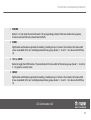
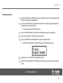
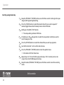
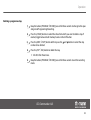
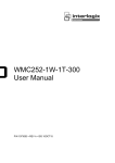
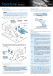
LED-Commander 16/2
DMX-controller
user manual
Musikhaus Thomann e.K.
Treppendorf 30
96138 Burgebrach
Germany
Telephone: +49 (0) 9546 9223-0
E-mail: [email protected]
Internet: www.thomann.de
25.08.2014, ID: 251852 | SW V1.0
Table of contents
Table of contents
1
General notes............................................................................................................................................... 4
2
Safety instructions..................................................................................................................................... 6
3
Features....................................................................................................................................................... 10
4
Installation.................................................................................................................................................. 11
5
Starting up.................................................................................................................................................. 13
6
Connections and operating elements........................................................................................... 14
7
Operation.................................................................................................................................................... 23
8
Technical specifications....................................................................................................................... 45
9
Protecting the environment.............................................................................................................. 46
LED-Commander 16/2
3
General notes
1
General notes
This user manual contains important information on safe operation of the device. Read and
follow all safety notes and all instructions. Save this manual for future reference. Make sure
that it is available to all persons using this device. If you sell the device, include the manual for
the next owner.
Our products are subject to a process of continuous development. We therefore reserve the
right to make changes without notice.
Symbols and signal words
This section provides an overview of the symbols and signal words used in this user manual.
Signal word
Meaning
DANGER!
This combination of symbol and signal word indicates an
immediate dangerous situation that will result in death or
serious injury if it is not avoided.
NOTICE!
This combination of symbol and signal word indicates a pos‐
sible dangerous situation that can result in material and
environmental damage if it is not avoided.
DMX-controller
4
General notes
Warning signs
Type of danger
Warning – danger zone.
LED-Commander 16/2
5
Safety instructions
2
Safety instructions
Intended use
This device is intended to be used to control spot lights, dimmers, light effects, moving heads
or other DMX-controlled devices. Use the device only as described in this user manual. Any
other use or use under other operating conditions is considered to be improper and may result
in personal injury or property damage. No liability will be assumed for damages resulting from
improper use.
This device may be used only by persons with sufficient physical, sensorial, and intellectual
abilities and having corresponding knowledge and experience. Other persons may use this
device only if they are supervised or instructed by a person who is responsible for their safety.
DMX-controller
6
Safety instructions
Safety
DANGER!
Danger for children
Ensure that plastic bags, packaging, etc. are disposed of properly and are not
within reach of babies and young children. Choking hazard!
Ensure that children do not detach any small parts (e.g. knobs or the like) from
the unit. They could swallow the pieces and choke!
Never let children unattended use electrical devices.
LED-Commander 16/2
7
Safety instructions
NOTICE!
External power supply
The device is powered by an external power supply. Before connecting the
external power supply, ensure that the input voltage (AC outlet) matches the
voltage rating of the device and that the AC outlet is protected by a residual cur‐
rent circuit breaker. Failure to do so could result in damage to the device and pos‐
sibly the user.
Unplug the external power supply before electrical storms occur and when the
device is unused for long periods of time to reduce the risk of electric shock or
fire.
NOTICE!
Risk of fire
Do not cover the device nor any ventilation slots. Do not place the device near
any direct heat source. Keep the device away from naked flames.
DMX-controller
8
Safety instructions
NOTICE!
Operating conditions
This device has been designed for indoor use only. To prevent damage, never
expose the device to any liquid or moisture. Avoid direct sunlight, heavy dirt, and
strong vibrations.
LED-Commander 16/2
9
Features
3
Features
n
n
n
n
n
n
n
n
n
16 devices controllable via DMX-512
2 × 8 memory slots each for scenes and chases
Faders for fade and scene time and speed, dimmer etc.
Operation modes: automatic, sound controlled and manual
Blackout and Full-on-function
Separate channel assignment
Backup and firmware update via USB
USB port for desk light
19" housing, 4 RU
DMX-controller
10
Installation
4
Installation
Unpack and carefully check that there is no transportation damage before using the unit. Keep
the equipment packaging. To fully protect the device against vibration, dust and moisture
during transportation or storage use the original packaging or your own packaging material
suitable for transport or storage, respectively.
Rack mounting
The unit has been designed for rack mounting in a standard 19-inch rack. It occupies four rack
units (RU).
LED-Commander 16/2
11
Installation
DMX connection
A 3-pin XLR socket is used as DMX output. The following diagram and table show the pin
assignment of the XLR socket.
1
Ground
2
DMX data (–)
3
DMX data (+)
DMX-controller
12
Starting up
5
Starting up
Establish all connections as long as the unit is switched off. Use the shortest possible highquality cables for all connections.
Connecting the power supply
Connect the included power adapter to the 9 V input of the device and then plug the mains
plug into the power outlet.
Switching the device on
Turn on the main switch on the rear side of the unit. Then the display shows the operating
mode and the corresponding indicator LED is on.
LED-Commander 16/2
13
Connections and operating elements
6
Connections and operating elements
Front panel
DMX-controller
14
Connections and operating elements
1 FIXTURE
Buttons 1 to 16 to select the control channels. The corresponding indicator LED shows whether the respective
channel is activated (LED on) or deactivated (LED off).
2 SCENE
Eight buttons with double assignment for enabling / disabling of up to 16 scenes. The indicator LEDs show which
scenes are enabled (LED is on). Switching between the key groups (banks) 1…8 and 9…16 is done via the Shift key
(3).
3 Shift key SCENE
Button to toggle the SCENE buttons. The two indicator LEDs show which of the two key groups (banks) 1…8 (red) or
9…16 (green) is currently active.
4 CHASE
Eight buttons with double assignment for enabling / disabling of up to 16 chases. The indicator LEDs show which
chases are enabled (LED is on). Switching between the key groups (banks) 1…8 and 9…16 is done via the Shift key
(5).
LED-Commander 16/2
15
Connections and operating elements
5 Shift key CHASE
Button to toggle the CHASE buttons. The two indicator LEDs show which of the two key groups (banks) 1…8 (red) or
9…16 (green) is currently active.
6 Display.
7 Buttons
and
Navigation buttons for scrolling the display and to select options.
8 MODE button
Button to change the operation mode. The corresponding LED shows the active operating mode: Auto, Music or
Manual.
9 SPEED fader
Slider to manually adjust the chase speed during playback.
10 FADE fader
Slider to manually adjust the fade time during playback.
DMX-controller
16
Connections and operating elements
11 BLACKOUT button
Button to turn the BLACKOUT function on or off. The corresponding indicator LED shows whether the function is
activated (LED on) or deactivated (LED off).
12 FULL ON button
Button to turn the FULL ON function on or off. The corresponding indicator LED shows whether the function is acti‐
vated (LED on) or deactivated (LED off).
13 PATCH | CLEAR button
Press this button for three seconds to cancel the channel assignments (scenes, chases or connected devices). Once
the corresponding indicator LED is lit, the channels can be reassigned. Press the button again for three seconds to
exit this mode.
14 PROGRAM | RECORD button
Press this button for three seconds to enable the Program mode. The corresponding indicator LED shows whether
the mode is activated (LED on) or deactivated (LED off). Press the button again for three seconds to exit this mode.
15 MIDI | IN SET button
Press this button for three seconds to open the menu for midi input assignment. Once the corresponding indicator
LED is lit, the midi inputs can be assigned using the SPEED fader or the and buttons. Press the button again for
three seconds to exit this mode.
LED-Commander 16/2
17
Connections and operating elements
16 TAP | DEL button
With this button you can delete and reverse inputs.
17 TILT button
Press this button to control the inclination of the assigned moving heads via the joystick (18). The corresponding LED
indicator flashes while the TILT mode is active.
18 Joystick to control the connected moving heads. To activate the joystick function either the TILT (17) or the PAN
mode (19) must be activated.
19 PAN button
Press this button to control the rotation of the assigned moving heads via the joystick (18). The corresponding LED
indicator flashes while the PAN mode is active.
20 AUX1 | AUX2 buttons
With these buttons you can activate the AUX channels (corresponding LED is lit) or deactivate them (LED is off).
21 DIMMER fader
Slider to manually adjust the DIMMER function. Press the corresponding flash button 8 to activate the slider control.
DMX-controller
18
Connections and operating elements
22 STROBE fader
Slider to manually adjust the STROBE function. Press the corresponding flash button 7 to activate the slider control.
23 SCENE fader
Slider to manually control a scene. Press the corresponding flash button 6 to activate the slider control.
24 SPEED fader
Slider to manually control the speed of a scene or a chase. Press the corresponding flash button 5 to activate the
slider control.
25 BLUE fader
Slider to manually control the colour intensity BLUE. Press the corresponding flash button 4 to activate the slider con‐
trol.
26 GREEN fader
Slider to manually control the colour intensity GREEN. Press the corresponding flash button 3 to activate the slider
control.
LED-Commander 16/2
19
Connections and operating elements
27 RED fader
Slider to manually control the colour intensity RED. Press the corresponding flash button 2 to activate the slider con‐
trol.
28 FUNCTION fader
Controller for manual adjustment of an active function. Press the corresponding flash button 1 to activate the slider
control.
DMX-controller
20
Connections and operating elements
Rear panel
LED-Commander 16/2
21
Connections and operating elements
29 Lockable DMX output socket.
30 DMX polarity switch.
31 USB port.
32 Audio input (line level, 100 mV to 1 Vpp).
33 MIDI OUT output socket.
34 MIDI THRU port.
35 MIDI IN input socket.
36 Connection socket for the 9 V power adapter for voltage supply.
37 Main switch to turn the unit on or off.
DMX-controller
22
Operation
7
Operation
After turning the unit on, it will run a short self-test. Then the unit automatically switches to
operating mode ‘Manual’ and is ready for use.
Selecting the operating mode
The LED Commander 16/2 operates in three different modes. To change the mode, press the
[MODE] button repeatedly until the desired mode appears in the display and the corre‐
sponding indicator lights up.
n
‘Auto’
In this mode you can use the sliders [FADE] and [SPEED] to adjust the fade in and out time
and speed. Use the buttons and to control the chase speed (setting range: 1 to 200 s).
n ‘Music’
In this mode you can use the and buttons to adjust the audio sensitivity (setting range:
0 to 100 %). Use the [FADE] slider to adjust the fade in and out time.
n ‘Manual’
In this mode you can use the and buttons to call each program step of a chase. Use the
[FADE] slider to adjust the fade in and out time.
LED-Commander 16/2
23
Operation
Assigning channels
1.
Keep the [PATCH ½ CLEAR] button pressed for three seconds.
2.
Press the [FIXTURE] button (1 to 16) to select the desired FIXTURE channel.
3.
Use the [SPEED] slider to choose the desired channel range.
4.
Use the [FADE] slider to select the desired DMX channel.
5.
Press the flash button for the function you want to assign.
6.
Repeat steps 2 to 5 to allocate the remaining sliders with functions.
Example: If the RED function (flash button 2) is assigned to DMX channel 21, the display shows
the following values:
DMX-controller
24
Operation
Cancelling channel assignment
1.
Keep the [PATCH ½ CLEAR] button pressed for three seconds.
2.
Deselect all active FIXTURE channels (all blue FIXTURE-LEDs off).
3.
Use the [FADE] and [SPEED] sliders to select the DMX channel whose assignment you
want to cancel.
4.
Press the respective flash button (1 to 8) to cancel the channel assignment.
The channel assignment is cancelled.
LED-Commander 16/2
25
Operation
Setting the dimmer channel
1.
Keep the [PATCH ½ CLEAR] button pressed for three seconds.
2.
Press the [FIXTURE] button (1 to 16) to select the desired FIXTURE channel.
3.
Keep the [DIMMER] button pressed for three seconds.
ð The display shows the following message:
Now, the channel to be programmed in the next step can be controlled via the
[DIMMER] control that is assigned to channel FIXTURE 01.
4.
Select the desired channel range using the [SPEED] sliders (1, 21, 41, 61 etc.).
5.
Select the desired DMX channel via the [FADE] slider.
6.
Keep the flash button [RED] pressed for three seconds.
ð The display shows the following message:
DMX-controller
26
Operation
Now, the channel RED of FIXTURE 01 can be controlled via the [DIMMER] control that
is assigned to the channel FIXTURE 01.
7.
Repeat steps 4 to 6 to allocate the remaining channels of FIXTURE 01.
The previously selected FIXTURE channel is displayed with the letter ‘M’ in the display.
In the example, this means that the [DIMMER] control that is assigned to channel FIXTURE 01
can control the maximum value of RED (CH 2).
LED-Commander 16/2
27
Operation
Calling scenes
1.
Deselect all active FIXTURE channels.
2.
Keep the [PATCH ½ CLEAR] button pressed for three seconds to delete all initial values of
the fader function.
3.
Press the [SCENE] button to select the desired scene. If needed, toggle between both
memory banks via the shift button.
You can link a number of scenes together and control them using the [FADE] slider.
The LEDs of all selected scenes light up blue.
DMX-controller
28
Operation
Programming scenes
1.
Keep the button [PROGRAM ½ RECORD] pressed for three seconds to change to the oper‐
ating mode Programming/Recording.
2.
Use the [FIXTURE] buttons to select the channel that you want to programme.
3.
Use the flash controls 1 to 8 to set the desired values.
4.
Press the [SCENE] button to select a memory slot. If needed, toggle between both
memory banks via the shift button.
5.
Press the [PROGRAM ½ RECORD] button and then for about one second the button for
the scene that you want to overwrite.
ð All device LEDs briefly flash.
6.
Keep the button [PROGRAM ½ RECORD] pressed for three seconds to exit the recording
mode.
With each programming, the existing scenes are overwritten with the new data.
LED-Commander 16/2
29
Operation
Calling chases
1.
Deselect all active FIXTURE channels (all blue FIXTURE-LEDs off).
2.
Keep the button [PATCH ½ CLEAR] pressed for three seconds to delete all initial values of
the fader function.
3.
Press the [CHASE] button to select the desired chase. If needed, toggle between both
memory banks via the shift button.
DMX-controller
30
Operation
Programming chases
1.
Keep the [PROGRAM ½ RECORD] button pressed for three seconds to change to the oper‐
ating mode Programming/Recording.
2.
Press the [CHASE] buttons to select the desired chase. If needed, toggle between both
memory banks via the shift button.
ð The corresponding CHASE LED lights up.
3.
Press the [FIXTURE] buttons to select the channel that you want to programme.
4.
Use the flash controls 1 to 8 to set the desired values.
5.
Press the [PROGRAM ½ RECORD] button to store the updated values.
ð All device LEDs briefly flash and the display shows the following values:
6.
Repeat steps 2 to 5 to add further programme steps.
7.
Keep the button [PROGRAM ½ RECORD] pressed for three seconds to exit the recording
mode.
LED-Commander 16/2
31
Operation
Inserting a programme step
1.
Keep the [PROGRAM ½ RECORD] button pressed for three seconds to change to the oper‐
ating mode Programming/Recording.
2.
Press the [CHASE] buttons to select the desired chase that you want to expand. If
needed, toggle between both memory banks via the shift button.
3.
Briefly press the [MIDI½ IN SET] button.
ð The corresponding indicator LED flashes.
4.
If needed, press the and
insert the program step.
5.
Press the [FIXTURE] buttons to select the channel that you want to programme.
6.
Use the flash controls 1 to 8 to set the desired values.
7.
Press the [PROGRAM ½ RECORD] button to store the updated values.
buttons to select the step number at which you want to
ð All indicator LEDs flash three times.
8.
Repeat steps 4 to 7 to insert further programme steps. The 16 memory slots can be
assigned to a total of 2,000 programme steps.
9.
Keep the button [PROGRAM ½ RECORD] pressed for three seconds to exit the recording
mode.
DMX-controller
32
Operation
Deleting a programme step
1.
Keep the button [PROGRAM ½ RECORD] pressed for three seconds to change to the oper‐
ating mode Programming/Recording.
2.
Press the [CHASE] buttons to select the chase from which you want to delete a step. If
needed, toggle between both memory banks via the shift button.
3.
Press the [MIDI ½ IN SET] button and then press the
number to be deleted.
4.
Press the [TAP ½ DEL] button to delete the step.
and
buttons to select the step
ð All LEDs flash three times.
5.
Keep the button [PROGRAM ½ RECORD] pressed for three seconds to exit the recording
mode.
LED-Commander 16/2
33
Operation
Deleting a chase
1.
Deselect all active FIXTURE, SCENE and CHASE channels (all blue LEDs off).
2.
Keep the button [PROGRAM ½ RECORD] pressed for three seconds to change to the oper‐
ating mode Programming/Recording.
3.
If needed, toggle between both memory banks ‘CHASE’ via the shift button.
4.
Press the [TAP ½ DEL] button and then the Chase button of the chase that you want to
delete.
5.
Keep the button [PROGRAM ½ RECORD] pressed for three seconds to exit the recording
mode.
DMX-controller
34
Operation
Assigning DMX channels to AUX
channels
1.
Keep the button [PROGRAM ½ RECORD] pressed for three seconds to change to the oper‐
ating mode Programming/Recording.
2.
Use the [FADE] and [SPEED] sliders to select the DMX channel that you want to assign.
3.
Press the [AUX1] or [AUX2] button to assign the DMX channel to the respective AUX
channel.
4.
Repeat steps 2 and 3 to assign any number of DMX channels.
5.
Keep the button [PROGRAM ½ RECORD] pressed for three seconds to exit the recording
mode.
The AUX channels can only be controlled via the [FADE] control.
LED-Commander 16/2
35
Operation
Assigning DMX channels to
flash controls 1 to 8
1.
Keep the button [PROGRAM ½ RECORD] pressed for three seconds to change to the oper‐
ating mode Programming/Recording.
2.
Use the [FADE] and [SPEED] sliders to select the DMX channel that you want to assign.
3.
Press the flash button of the desired control to assign the DMX channel.
4.
Repeat steps 2 and 3 to assign any number of DMX channels.
5.
Keep the button [PROGRAM ½ RECORD] pressed for three seconds to exit the recording
mode.
DMX-controller
36
Operation
Renaming flash functions
1.
Switch the device off
2.
Keep the buttons [PROGRAM ½ RECORD], [DIMMER] and [PATCH ½ CLEAR] pressed simulta‐
neously and turn the device on again.
ð The following message appears in the display after two seconds:
3.
Press the flash button of the function that you want to rename.
4.
Now you can use the joystick to change the description in the display (move it right / left
to move the cursor, move it up / down to change the character).
5.
Repeat steps 3 and 4 to rename further flash function, if required.
6.
Confirm the updated description(s) via [PROGRAM ½ RECORD].
7.
Switch the device off and on again to work with the new settings.
LED-Commander 16/2
37
Operation
MIDI functions
The MIDI function allows you to combine two DMX controllers together, or to control the con‐
troller via a MIDI keyboard.
1.
Keep the button [MIDI ½ IN SET] pressed for three seconds to change to the operating
mode MIDI.
2.
Select a MIDI channel (1 to 16) via buttons
3.
Keep the button [MIDI ½ IN SET] pressed for three seconds to exit the MIDI mode.
MIDI value
Function
Description
0-15
SCENE1-16
Turning scenes 1-16 on / off
16-31
CHASE1-16
Turning chases 1-16 on / off
32
MANUAL
Manual show control
33
MUSIC
Sound controlled show
34
AUTO
Automatic show
35
AUX1
Turning AUX1 on / off
36
AUX2
Turning AUX2 on / off
DMX-controller
38
and .
Operation
MIDI value
Function
Description
37
Manual show control
38
Manual show control
39
TAP
Automatic show
…
…
…
126
BLACK OUT
Function BLACK OUT active
LED-Commander 16/2
39
Operation
Saving settings externally
You can save various device settings to a USB drive.
1.
Connect the USB drive to the USB port of the device.
2.
Keep the buttons [MODE] and pressed for two seconds until the display shows the
message ‘Press fixture ½ key save file’ .
3.
Press the button of the FIXTURE channel whose settings you want to save.
ð The saving progress is shown on the display.
All channel settings are stored together in the file ‘led-commander 16-2’ on the USB
drive.
DMX-controller
40
Operation
Loading stored settings
You can load saved device settings from a USB drive into the units memory.
1.
Connect the USB drive with the saved setting values to the USB port of the device.
2.
Keep the buttons [MODE] and pressed for two seconds until the display shows the
message ‘Press fixture ½key loader file’ .
ð The LEDs of those channels for whom settings have been found on the USB drive
light up.
3.
Press the button of the FIXTURE channel whose settings you want to load.
ð The loading progress is shown on the display. Then the display returns to the pre‐
vious status.
LED-Commander 16/2
41
Operation
Resetting to factory defaults
1.
Turn off the device with the main switch.
2.
Press the buttons [PROGRAM ½ RECORD], [TAP ½ DEL] and [PATCH ½ CLEAR] simultane‐
ously and then turn the unit on again.
ð After two seconds, the display shows the following message:
After resetting to factory defaults, the FIXTURE channels are set up as follows:
FIXTURE 1
FIXTURE 2
FIXTURE 3
FUN CH1
FUN CH11
FUN CH21
FUN CH151
Red CH2
Red CH12
Red CH22
Red CH152
DMX-controller
42
…
FIXTURE 16
Operation
FIXTURE 1
FIXTURE 2
FIXTURE 3
…
FIXTURE 16
Green CH3
Green CH13
Green CH23
Green CH153
Blue CH4
Blue CH14
Blue CH24
Blue CH154
SPEED CH5
SPEED CH15
SPEED CH25
SPEED CH155
COLOUR CH6
COLOUR CH16
COLOUR CH26
COLOUR CH156
STROBE CH7
STROBE CH17
STROBE CH27
STROBE CH157
No Func.CH8
No Func.CH18
No Func.CH28
No Func.CH158
PAN CH9
PAN CH19
PAN CH29
PAN CH159
TILT CH10
TILT CH20
TILT CH30
TILT CH160
LED-Commander 16/2
43
Operation
Firmware update
Proceed as follows to bring the firmware of the unit up to date. To do so, you need a com‐
pletely blank USB drive that is formatted with FAT32 format.
1.
Create a folder ‘led-commander16-2’ in the root directory of the USB drive.
2.
Copy the file containing the current firmware version into the folder ‘ledcommander16-2’.
3.
Connect a USB drive with the latest firmware version to the USB port of the device.
4.
Turn the device off.
5.
Keep the buttons [PROGRAM ½ RECORD], [MODE] und
again.
pressed and turn the device on
ð After two seconds, the display shows the message ‘Press any button ½ Update
firmware’ .
6.
Press any key to start the firmware update.
7.
After the installation is complete, the display shows the message ‘Update succeeded ½
Please reboot’ .
8.
Then, turn off the device and after a few seconds turn it on again.
ð The unit will now start with the updated firmware.
DMX-controller
44
Technical specifications
8
Technical specifications
Operating supply voltage
DC 9…12 V
Communication protocol
DMX 512
Dimensions (W × D × H)
482 mm × 175 mm × 75 mm
Weight
3.5 kg
LED-Commander 16/2
45
Protecting the environment
9
Protecting the environment
Disposal of the packaging mate‐
rial
For the transport and protective packaging, environmentally friendly materials have been
chosen that can be supplied to normal recycling.
Ensure that plastic bags, packaging, etc. are properly disposed of.
Do not just dispose of these materials with your normal household waste, but make sure that
they are collected for recycling. Please follow the notes and markings on the packaging.
Disposal of your old device
This product is subject to the European Waste Electrical and Electronic Equipment Directive
(WEEE). Do not dispose with your normal household waste.
Dispose of this device through an approved waste disposal firm or through your local waste
facility. When discarding the device, comply with the rules and regulations that apply in your
country. If in doubt, consult your local waste disposal facility.
DMX-controller
46
Musikhaus Thomann e.K. · Treppendorf 30 · 96138 Burgebrach · Germany · www.thomann.de