1
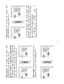
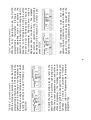
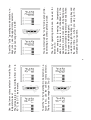
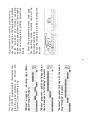
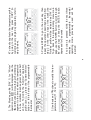
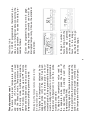
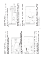
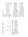
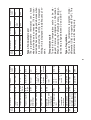
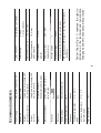
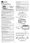
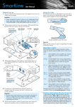
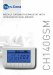
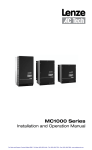
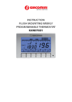
WEEKLY PROGRAMMABLE THERMOSTAT
CH151-CH152
CH150
2
Technical data ........................................................25
“Holiday” operating mode ................................10
Programmable thermostat programming .........13
Preset programs ..............................................13
“OFF” function .................................................12
“Jolly” operating mode .....................................10
Configuring the programmable thermostat ......21
Fastening the programmable thermostat onto the
base .................................................................20
Fitting the batteries ..........................................20
Electric connections ........................................19
Fastening the base ..........................................18
Installation .............................................................18
Replacing the batteries ....................................16
Maintenance ..........................................................16
Statistical data .................................................15
Displaying the temperature detected by the
separate probe ................................................15
“Automatic” operating mode ..............................8
“Manual” operating mode ..................................7
Operating modes ...............................................7
Summer/Winter selection ..................................7
Setting the date and time ..................................6
User manual ............................................................6
Indications .........................................................5
Controls .............................................................4
Controls and indications ..........................................4
Introduction ..............................................................3
INDEX
The programmable thermostat is available in
the following version:
•
CH150 Programmable thermostat with 5A
relay.
•
CH150-16 Programmable thermostat with
16A relay
Programmable thermostat CH150 is suitable
to measure the ambient temperature and to
control the heating and air conditioning system
to which it is connected. The operating mode
can be chosen between the preset ones or can
be customized according to user’s needs.
The wide display shows the temperature
profile — i.e.: the relationship between the
time table and the temperature to be kept —,
as well as the measured temperature, relative
humidity, calculated perceived temperature,
time and day of the week.
The programmable thermostat is battery
powered. Both settings and data are stored
in a non-volatile memory capable of retaining
them even when batteries are down.
Introduction
3
Unless otherwise specified, the instructions
contained in this manual apply to every
programmable thermostat model.
The programmable thermostat comes in three
colours:
white, silver (CH151 series) and anthracite
black (CH152 series).
For programmable thermostats CH150 and
CH150-16 the following external interfaces are
available:
•
Separate temperature probe;
•
Telephone activator with GSM modem, for
remote management via SMS messages.
The telephone activator enables the following:
•
remote
communication
with
the
programmable thermostat to know the
ambient temperature or the status of the
heating or air conditioning system;
•
remote management of the programmable
thermostat operating modes.
2
3
4
5
6
11
10
9
8
7
1. Button used to select the “Manual” operating
mode or increase a value (▲) *
2. Button used to select the “Automatic”
operating mode or decrease a value (▼) *
3. Button used to select the “Holiday” operating
mode or go back to the previous data item (◄)
*
4. Button used to select the “Jolly” operating
mode or go to the next data item (►) *
5. Button used for the “OFF” or “Enter”
functions *
1
Controls
Controls and indications
4
* The function associated with the button or
selector depends on the current operating
mode. It is highlighted by the icon placed
above.
6. Button used for the “Programming” or “Copy”
or “Statistical data displaying” functions *
7. Rotary selector for temperature correction:
T1, Manual temperature, Jolly temperature,
and
Antifreeze temperature *
8. Rotary selector for correcting temperature
T2 or the Jolly operating mode duration *
9. Rotary selector for correcting temperature
T3 or the Jolly operating mode duration
10. Summer/Winter switching key and
keyboard lock
11. Programmable thermostat reset button
11
10
2
9
3
5
8 7 6
4
1. Time
2. Temperature profile
3. Temperature value T1 or “Jolly” operating
mode duration (days)
4. Temperature value T2 or “Jolly” operating
mode duration (hours)
5. Temperature value T3
6. System ON in Summer operation
7. System ON in Winter operation
8. Relative humidity percentage
9. Perceived temperature (displayed by the
degree)
10. Ambient/external temperature
13 12
Indications
14
1
5
11. Current day (1 = Monday … 7 = Sunday;
8 = Holiday)
12. Winter operation
13. Summer operation
14. Battery charge level
1. Enter the programming menu main page.
The operating mode currently used will be
interrupted temporarily. Choose the time
setting function.
Setting the date and time
To set the current time and date, proceed as
follows:
To operate the programmable thermostat after
it has been installed, proceed as follows:
1. Set the date and time.
2. Select the Summer/Winter operation.
3. Select the operating mode.
User manual
6
4.Modify the day setting by means of the ▲
button, then press ENTER to go back to the
main page of the programming menu.
3. Modify the minute setting by means of the
▲ and ▼ buttons, then go to the day setting
by means of the ► button.
2. Modify the hour setting by means of the ▲
and ▼ buttons, then go to the minute setting
by means of the ► button.
Winter
Summer
Summer/Winter selection
To shift from the Summer
operation (heating system) to
the Summer operation (cooling
system), and vice versa, keep the
Summer/Winter button depressed
for at least 4 seconds. The
selected operation will be shown
on the display by means of the
“Winter” or “Summer” icons.
5. Press ENTER again to exit the programming menu. The programmable thermostat
operating mode previously interrupted will be
resumed.
7
“Manual” operating mode
With the Manual operating mode, the
programmable
thermostat
adjusts
the
operation of the heating or cooling system in
order to always keep the same temperature.
To select “Manual”, press MAN.
Operating modes
The CH150 programmable thermostat features
four different operating modes: Manual,
Automatic, Holiday and Jolly (in addition to the
OFF function).
The temperature level can be modified during
operation by means of the lower rotary selector
located on the right side of the programmable
thermostat. The temperature can be changed
from 2°C to 40 °C by 0.1°C increments.
8
The three temperature levels used can be
modified during operation by means of the
rotary selectors located on the right side of the
programmable thermostat.
“Automatic” operating mode
With the “Automatic” operating mode, the
programmable
thermostat
adjusts
the
operation of the heating or cooling system by
following the profiles defined for the various
days of the week. To select “Automatic”, press
AUTO.
Temperature T2 cannot be higher than temperature T3 or lower than temperature T1.
Temperature T3 cannot be lower than
temperature T2 or higher than 40 °C.
During Summer operation, temperature
T3 features an upper limit of 30°C. When this
value is exceeded, T3 will take the OFF value,
which will involve switching the system off.
9
If no customization has been made, the
automatic operating mode will function with
the stored temperature profiles, i.e. the preset
ones (refer to «Preset programs»).
To customize the profiles, refer to
«Programmable thermostat programming».
Temperature T1 cannot be higher than
temperature T2 or lower than 2 °C.
To modify the temperature levels, refer to the
description of the “Automatic” operating mode.
When the preset programs are used (refer to
«Preset programs»), the “Holiday” mode will
follow the profile envisaged for Saturdays and
Sundays. To create a customized “Holiday”
program, refer to «Programmable thermostat
programming».
“Holiday” operating mode
With the “Holiday” operating mode, the CH150
programmable thermostat CH150 adjusts the
operation of the heating or cooling system by
following one single temperature profile, which
is valid for all days. To select “Holiday”, press
HOLIDAY.
10
The “Jolly” temperature value and the
operating mode duration can be modified by
means of the rotary selectors located on the
right side of the programmable thermostat.
“Jolly” operating mode
With the “Jolly” operating mode, the CH150
programmable thermostat interrupts the
current operating mode and adjusts the
operation of the heating or cooling system to
keep the “Jolly” temperature during the entire
time set (1 hour to 99 days and 23 hours, by
1 hour increments). After this time – which is
displayed like a countdown – has elapsed,
the previous operation of the programmable
thermostat will be resumed. To select “Jolly”,
press JOLLY.
To set the “Jolly” operating mode duration, i.e.
hours («h»), use the central rotary selector.
The hours can range from 0 to 23.
Use the lower rotary selector to modify the
temperature level.
The temperature can be modified from 2°C to
40 °C, by 0.1 °C increments.
11
The “Jolly” operating mode can be used, for
instance, to:
• save energy by lowering the temperature
when the house is not inhabited at the
weekends or winter vacation, while being sure
that a comfortable temperature will exist when
the house is inhabited again);
• extend the night heating or cooling beyond
the usual time, i.e. when you stay up in the
company of your guests.
You can interrupt the “Jolly” mode at any time,
by selecting any other operating mode.
To set the “Jolly” operating mode duration, i.e.
days («d»), use the upper rotary selector.
The days can range from 0 to 99.
The “Antifreeze” temperature can be modified
from 2°C to 7°C (by 0.1°C increments), by
using the lower rotary selector. If a temperature
of less than 2°C is set, the system will be fully
turned off and the antifreeze protection will be
lost.
The programmable thermostat adjusts the
operation of the heating system to keep the
“Antifreeze” temperature, in order to reduce
the energy consumption and, at the same
time, avoid any damage caused by extremely
low temperatures.
Winter operation
“OFF” function
The “OFF” function can be activated by pressing OFF.
12
The system will be fully turned off and the
“OFF” message will appear on the display,
without any temperature profile.
Summer operation
“Summer” program (All days of the week,
plus “Holiday” program)
“Winter” program – public holidays (Saturdays, Sundays and “Holiday” program)
“Winter” program – working days (Mondays through Fridays)
Preset programs
The CH150 programmable thermostat features two preset programs (i.e. “Winter” and
“Summer”) for quicker start-up.
13
1. Enter the programming menu main page.
The operating mode currently used will be
interrupted temporarily.
Choose the temperature profile customization
function.
Programmable thermostat programming
You can customize the temperature profiles
for the “Automatic” and “Holiday” operating
modes, so as to adapt them to your own needs.
To set new temperature profiles, proceed as
follows:
3. Use the ▲ and ▼ buttons to modify the temperature level (T1, T2 or T3).
2. The Monday profile (DAY 1) for “Winter”
operation (icon
) will be displayed. Use the
◄ and ► buttons to move the bar chart blinking
segment to the time at which the temperature
is to be modified. Each segment equals half
an hour. To modify the “Summer” operation
), press the “Summer/Winter”
profile (icon
button on the left side of the programmable
thermostat.
14
If no button is pressed within the next three
minutes, the programmable thermostat
operating mode previously used will be
resumed.
5. Press ENTER to go to the next day, then
repeat the operations described starting from
step 2 for the other days of the week (the
“Holiday” profile will be indicated as DAY 8).
To go back to the programming menu main
page, use the ENTER button to scroll through
the eight days or keep the ENTER button
depressed for 3 seconds.
4.To directly duplicate the temperature profile
by going to the next day, press COPY (to
customize every single day separately, refer to
step 5 below).
Displaying the temperature detected by
the separate probe
To display the temperature detected by the
separate probe (only if the latter has been
configured as an external probe or floormounted probe), the programmable thermostat
must be configured (refer to <<programmable
thermostat configuration>>) and the probe
must be connected.
To display the temperature value read by
the separate probe, press the button of
the operating mode currently used (the
temperature will blink).
To display again the temperature detected by
the programmable thermostat, press again the
button of the operating mode currently used
(the temperature will not blink any longer).
Preset parameter reset
To resume the preset temperature profiles
and values (T1-T2-T3-Temperature used
with the Manual mode, Temperature used
with the Jolly mode, Antifreeze temperature,
OFF function), keep the ▲ and ▼ buttons
depressed simultaneously when you are in the
temperature profile programming mode.
15
2. Page 1: number of
hours during which the
system was operated
on the previous day (6
hours in the image).
Use the ► button to go
to the next page.
1.Enter the programming menu main page.
The operating mode currently used will be
interrupted temporarily. Choose the statistical
data function.
Statistical data
The CH150 programmable thermostat provides a set of statistical data concerning the
system operation. To access this data, proceed as follows:
6. Press the ENTER button twice to go back to
the operating mode previously used.
4.Page
3:
minimum
temperature
reached
on the current day,
and time at which such
minimum
temperature
was reached (15.8°C at
03.15 a.m. in the image).
Use the ► button to go to
the next page.
5. Page 4: maximum
temperature
reached
on the current day,
and time at which such
maximum temperature
was reached (22.5°C at
09.08 p.m. in the image).
3. Page 2: total number
of hours during which
the system has been
switched on and operating since its first start-up
(16 hours in the image).
Use the ► button to go to the next page.
Press the ▲ and ▼ buttons simultaneously to
reset the total system switch-on hours.
16
To clean the programmable thermostat use a
soft cotton cloth and no detergent. Do not use
paper handkerchiefs to clean the touch screen.
Maintenance
If after replacing the batteries, the display
only shows the message OFF or ON, press
the icon key with ENTER after refitting the
programmable thermostat on the base.
To remove the programmable thermostat from
the base proceed as follows:
• remove the jack plug from the telephone
activator, if any;
• pull the left and right sides of the
programmable thermostat, without applying
force to selectors.
Replacing the batteries
When the battery charge starts to lower,
symbol
on the display will start flashing.
If the “bAtt” parameter is set to “On” or to
“Off” (see paragraph <<configuring the
programmable thermostat>>) and batteries are
not replaced within 15 days, the programmable
thermostat will turn off automatically and the
display will show the message “OFF” or “On”
instead of the temperature value.
Settings and data are however stored in the
non-volatile memory.
17
Important: Standard battery life is approx. 1
year. You are recommended to replace batteries
at the beginning of system operating season to
prevent batteries from running down when you
are away from home, e.g. during Christmas
holidays.
The batteries shall be properly disposed of in
special containers.
With the “bAtt” parameter off (see paragraph
<<configuring the programmable thermostat>>),
and symbol
flashing, batteries shall be
changed as soon as possible to prevent that
battery charge becomes insufficient for regular
programmable thermostat operation.
Fastening the base
The programmable thermostat comes with a
base suitable for wall mounting or for flushmounting in three-module rectangular or round
boxes.
Programmable thermostat installation involves
the following operations:
• Fastening the base.
• Electric connections.
• Fitting the batteries.
• Fastening the programmable thermostats
onto the base.
• Configuring programmable thermostat parameters.
Caution: The programmable thermostat shall
be installed by qualified personnel only, in
compliance with the current regulations in
force.
Installation
18
83
60
To ensure correct operation the base shall
be installed at about 1.5 metres above the
floor level and far from heat sources (heating
radiators, direct sunlight, etc.), doors and
windows.
Make sure that the base is properly secured
and it is not deformed. Check that the
programmable thermostat multi-pole connector
is placed at the bottom left corner.
Separate the base from the programmable
thermostat levering on the slot located at the
bottom of the base by means of a proper tool.
SPACING DIMENSIONS FOR FIXING THE BASE
60
Connect the two wires of the heating or airconditioning system to the terminals 1 and 2,
as shown in the figure.
Terminals are suitable for flexible cables with
Connecting the heating or air-conditioning
system
Protection guard fastening screw
Electric connections
Before making connections, remove the
terminal protection guard (keep it together with
the fastening cross-slotted screw).
19
LOAD
4
1
2
Programmable thermostat
relay terminal block
LOAD = burner - circulation pump
Phase
the
separate
temperature
Connect the two wires of the separate
temperature probe to terminals A and B, as
shown in the figure.
Connecting
probe
Warning: Make sure the relay load value is not
exceeding the values specified in «Technical
data».
Neutral
2.5 mm² max section.
Terminal 4 is free and may be used for
signalling or other use, as necessary.
Connect the three wires of the telephone
activator to terminals 1, 2 and 3, as shown in
the figure.
As an alternative, the activator may be
connected through the 3.5 mm jack plug set
on the left side. Once connections are over,
refit the terminal protection guard removed
previously.
Connecting the telephone activator
20
CH150
terminal block
3
2
1
B
A
Fastening the programmable thermostat
onto the base
Press by hand the programmable thermostat
onto the base, make sure the multi-pole
connector fits properly. The programmable
thermostat will click into position.
Fitting the batteries
Fit two long-life 1.5 V AA alkaline batteries
into the back of the programmable thermostat,
observe the specified polarity. After fitting the
batteries the programmable thermostat will
turn on automatically.
Separate
temperature
probe
1 2 3
CTx terminal block
Configuring the programmable thermostat
1. Press the SET / PROG key [key 6]. The
operating mode being currently used will be
temporarily stopped and it will be resumed automatically at the end of programming.
2. Keep the SUMMER / WINTER switching key
Programmable thermostat configuration enables to customize the operating parameters.
To open the configuration program, proceed
as follows:
Warning: The programmable thermostat shall
be configured by qualified personnel only.
21
To go back to the initial page of the programming menu, press the ENTER key [key 5]
which will save changes.
If no key is pressed within 3 minutes, the programmable thermostat will quit the configuration program and will resume the operating
mode being used previously, without saving
changed settings.
To cancel changed settings and to reset preset
configuration parameter values, keep keys ▲
[key 1] and ▼ [key 2] pressed simultaneously
for about 4 seconds.
[key 10] pressed for about 5 seconds.
Every configuration parameter featuring preset
settings is identified on the display by an index
and a writing. To change parameter values use
keys ▲ [key 1] and ▼ [key 2]; use key ► [key
4] to move across parameters.
Type of regulation Std
ProP
Thermal
differential
Regulation band
Regulation period
Separate
Sect
temperature probe
configuration
Floor temperature Tflo
limit
Ambient
temperature
correction
Optimization
Max. optimization
duration (hours)
Pump anti-seizure Pu
3
3A
3A
3B
4
4A
5
6
6A
7
OPtH
Opt
Corr
Per
BAnd
DIFF
Temperature scale CELS o °C / °F
FHAr
2
Preset
value
2 °C
LO
Std
ON/OFF
1h – 5h
ON/OFF
-4.0 °C
to +4.0 °C
15 °C –
45 °C
OFF
2h
OFF
0.0 °C
27.0 °C
--- / FLO / In --/ Out
5 / 10 / 20 10
minutes
minutes
1 °C – 4 °C
(step 0.1°C)
HI / LO
o Std / ProP
°C
rEL / rAd / --- none
Type of connected COn
card
Values
1
Writing
Parameter
Index
22
Software release
Low battery
Parameter
SOFt
bAtt
Writing
Preset
value
xxx
xxx
--- / On / OFF
OFF
Values
Type of regulation
To select the temperature regulation mode:
differential (Std) or proportional (ProP). This
parameter is used for heating only.
Temperature scale
To select the temperature scale to be displayed: Celsius (centigrade) or Fahrenheit.
When choosing the Fahrenheit scale, temperatures may range between 0.0 and 99.9 °F.
Type of connected card
The programmable thermostat can check
whether the base is connected. If it is not connected dashes will be displayed whereas when
it is connected the writing rEL is displayed.
Writing rAd is displayed in radiofrequency versions.
9
8
Index
Separate temperature probe configuration
Regulation period
To set the regulation cycle length (ON period
+ OFF period) when the proportional temperature regulation mode is chosen. Select 5
minutes for low-inertia systems (fan-coil type),
10 minutes for average-inertia systems (aluminium radiator type) and 20 minutes for highinertia systems (cast-iron radiator type).
Regulation band
To select the proper value according to the
thermal gradient of the system (broadband
for high gradients– narrow band for low gradients).
Thermal differential
To set the thermal differential value to be used
when choosing the differential temperature
regulation mode. Continuous switching on and
off can be avoided by choosing a proper differential value according to the thermal inertia of
the heating system. It is recommended to set a
low thermal differential (LO) in heating systems
with radiators and high thermal differential (HI)
in heating systems with fan-coils.
23
Floor temperature limit
To set the temperature limit value read by the
The programmable thermostat may be connected to a separate temperature probe. Probe
operation is determined by this parameter.
• Probe off (---): the temperature value detected by the probe is not used (although the
probe is connected).
• Floor probe (FLO): when the temperature
detected by the probe reaches the value set in
the Floor temperature limit parameter, the system will be turned off regardless of the temperature read by the programmable thermostat.
• Ambient probe (In): system regulation is
based on the temperature value detected by
the separate probe. This temperature value is
displayed instead of the temperature value detected by the internal probe of the programmable thermostat. The separate ambient probe
is used when the programmable thermostat is
necessarily located in a room other than the
one the temperature of which is to be controlled;
• External probe (Out): has no effect on system regulation, it is just used to know another
temperature, e.g.: the outside temperature.
Pump anti-seizure
To turn the system on for 1 minute a day (h
23.58), thereby operating the water circulation pump and preventing it from seizing. This
takes place only if the system has never been
Max. optimization duration
To set the max. duration (expressed in hours)
of the advance switch-on time calculated by
optimization.
Optimization
To calculate the advance switch-on time required to reach the desired temperature at the
set time, considering the system thermal inertia. Optimization takes place only at the first
switch-on of the day, i.e.: the first programmed
passage from a temperature to a higher one.
Ambient temperature correction
To sum/subtract an offset value to/from the
temperature value read by the programmable
thermostat.
separate probe which turns the system off
when the floor probe is used (for floor heating
systems).
24
Low Battery
To determine the relay status when batteries
are flat for over 15 days. If this parameter is
excluded (---), the programmable thermostat
will keep on controlling the relay as required by
regulation until the remaining battery charge
allows for it.
turned on during the day.
Non-volatile memory
1BU
Class A
2 °C – 40 °C
2 °C – 7 °C
T45
Setting storage
Micro-disconnection
Software
Temperature regulation
range
Anti-freeze temperature
regulation range
Max. temperature
IP20
Protection
Double
Screw clamps 3.5 mm twopole jack plug
Electric connections
Insulation
Telephone activator
Separate temperature probe
Inputs
(CH150-16)
25
4000V
Fantini Cosmi S.p.A. It reserves the right to
introduce all the technical and construction
changes as it deems necessary, without notice.
ErP classification: ErP Class IV; 2% (EU Reg. 811/2013
- 813/2013)
Complies with EN 60730-1 and second parts
2
Impulse Voltage
20% - 90%
4 K/h
10 m max
Pollution degree
Relative humidity
displayed value
Reference thermal
gradient
Separate temperature
probe distance
155 X 91 X 20
1 single-pole relay voltage 250
Va.c. rating 16(4)A
Dimensions (L x H x D)
Outputs
(CH150/CH151/CH152)
6 keys
3 rotary selectors
1 single-pole relay voltage 250
Va.c. rating 5(3) A
Outputs
Backlighted LCD display
Local controls
about 1 year
Battery life
Local indication
2 AA alkaline batteries, 1.5 V
Power supply
TECHNINIAI DUOMENYS
NOTE
NOTES
26
DISPOSAL OF PRODUCTS
The crossed out wheeled dust bin symbol indicates that products must be collected and disposed of
separately from household waste. Integrated batteries and accumulators can be disposed of with the
product. They will be separated at the recycling centres. The black bar indicates that the product was
placed on the market after August 13, 2005. By participating in separate collection of products and
batteries, you will help to assure the proper disposal of products and batteries and thus help to prevent
potential negative consequences for the environment and human health. For more detailed information
about the collection and recycling programmes available in your country, please contact your local city
office or the shop where you purchased the product.
www.fantinicosmi.com
EXPORT DEPARTMENT
Ph +39 02 95682229 | [email protected]
FANTINI COSMI S.p.A.
Via dell’Osio, 6 20090 Caleppio di Settala, Milano - ITALY
Tel. +39 02 956821 | Fax +39 02 95307006 | [email protected]
GB79293D