1
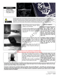
SECTION 3
-
WS-66 Prepping
Remove internals
Lubrication
Reassemble
NOTES OR COMMENTS
by
14
1p
ai
nt
ba
l
Before starting take the time to ensure that your
semi trigger is in SAFETY ON mode. Press the
safety knob on the left side of the trigger frame
until it is flush with the trigger frame – the section
with the red ring should not be visible, and the
safety knob should now protrude out the right
side of the trigger frame. Test the trigger – it
should not allow a full trigger pull. Your safety is
now ON.
Depressing the knob from the right, will put the
safety OFF and make the marker ready to fire
Before ANY internals are removed, a few external
parts need to be detached to allow full access to
all areas which will allow for removal of the
internal bolt, striker and other parts.
The carry handle needs to be removed in order to
access the cocking mechanism and allow for
removal of the cocking pin which holds the pin
and striker assembly together internally.
l.c
om
This support sheet covers all required steps toward removing the rear -end internals, lubricating, cleaning and reassembling. This should be done
prior to any use of the marker, and also after each full day of usage, in particular if the marker was used in rugged, dusty, wet, or other harsh
environments during play, or if the marker broke paint during play.
se
d
To remove simply unscrew the two retainer
screws until the carry handle is loose on the
weaver rail – you do not need to unscrew these
completely – only enough to remove the handle
from the weaver rail (flat top)
ec
om
pr
es
Next….use the proper hex wrench tool to loosen
the retainer screw on inside the channel of the
weaver rail (flat top). This screw holds the cocking
channel plate in place and needs to be removed
in order to slide this plate off and expose the
internals of the cocking handle mechanism.
Do not over-tighten this screw when reinstalling. It can cause the plate to rub
against the cocking assembly below it
and inhibit the proper snap-return of
the cocking handle once pulled.
R
The cocking channel plate can be removed from
either the front or back of the channel. To remove
it from the front, the Powerfeed (pictured) will
have to be removed.
To remove through the back of the channel,
simply pull the cocking handle back about ½ way
and slide it out.
Warsensor WS-66 User Manual
PREPPING & LUBE INTERNALS
Revision 1 printed
5/30/2004
Pull the cocking handle back slightly (do not
engage the full length of the cocking mechanism).
While holding this slightly extended, maneuver the
cocking channel cover plate out the back of the
channel.
You may need to slightly bend it upward to clear
the cocking handle. The plate is flexible enough
and can be bent to accommodate, however be
careful not to bend it too far as this will damage it.
l.c
Incorrect assembly of the cocking pin
where it does not engage both striker
and bolt, can cause it to become
damaged, bent, broken or may cause
damage to the internal channels of the
receiver.
ba
l
Gripping the cocking handle….gently pull it
upward and out of the channel taking care not to
damage or stretch the spring.
The spring has a loop which sits over the head of
a retainer screw. Leave the screw intact, and
simply guide the spring-loop off of the screw head
to release the entire cocking mechanism.
om
Pull the plate completely out – exposing the
internals of the cocking system
Depending on the severity of the
damage the smooth flow of the bolt or
striker could be inhibited and cause
cocking or re-cocking problems with
the marker
14
1p
ai
nt
You should now clearly see the cocking pin. This
is the pin which connects the bolt and striker. It
only goes in 1 way – please observe its
orientation when removing it. When re-installing
please ensure the bolt and striker are engaged
properly by sliding the cocking handle back and
forth – both pieces should move together.
With the cocking pin removed the bolt and striker
are now disengaged inside the marker and can be
removed for cleaning, lubrication and/or o-ring
maintenance (whichever is required).
se
d
by
To remove the internals (bolt, striker) first remove
the retainer pins from the rear of the marker. Tap
them gently on the small side and simply pull to
remove from receiver body.
The stock securing ring should first be loosened
using the stock wrench supplied in your
Warsensor toolkit.
When removing the retainer pin from
the striker/velocity cap section (bottom
unit) of the receiver, please take
caution to hold the velocity cap as the
internal spring is under some tension
and can cause parts to fly out.
To remove the stock (upper section,
first loosen the stock by turning it
counterclockwise with the supplied
stock wrench (see section 1)
R
ec
om
pr
es
Pull stock outward gently but with firm action – if it
is tight, try loosening the securing ring a bit more.
Use the supplied stock wrench for this to avoid
any damage to the stock securing ring.
It may help to wiggle the stock a bit, using a slight
circular
motion
while
pulling
outward.
Next, undo the retainer pin in the lower portion of
the receive. This pin holds the velocity cap in
place as well as its internals. Please note that the
spring will have tension on the cap – DO NOT
REMOVE PIN WITHOUT SECURING THE CAP
WITH A FREE HAND…..the tension on the spring
could cause the internals to POP OUT.
Warsensor WS-66 User Manual
PREPPING & LUBE INTERNALS
Revision 1 printed
5/30/2004
After safely removing the striker / velocity cap you
will have access to the first portion of the rear end
internals of the WS-66 marker
Carefully remove the striker spring guide, striker
spring and the circular spring buffer. You may
have to use the end of a flat screwdriver or other
blunt object to aid in removing the circular rubber
buffer section of the internals.
l.c
Do not be afraid to lubricate these
parts.
Do not use excessive lube or thick
lube – this may create a resistance
effect and inhibit marker recocking.
Sometimes o-rings may look good to
the naked eye, but can be damaged.
If the ureathane orings on the bolt are
discolored – change them
ba
l
Once the internals are out – note their assembly
orientation. Also note the lubrication points as
illustrated. These should all be properly lubricated
using either 3-in-1 gun oil, paintball marker
lubricant, Teflon grease, or Silicon grease –
whichever is most readily available to you.
om
Gently tilt the receiver and slide the striker and
bolt out of the receiver.
ec
om
pr
es
se
d
by
14
1p
ai
nt
Bottle o-rings fit perfect on both bolt and striker.
Repeat all steps in reverse for proper assembly of the internal section. Paying close attention to the orientation of the striker and bolt
assembly – The bolt has an air channel hole approximately centered on it – THIS NEEDS TO POINT TO THE BOTTOM OF THE RECEIVER
WHEN INSTALLED – or the marker will not function properly:
R
Striker assembly should be as follows:
st
1 insert the striker,
nd
2 insert the striker buffer,
rd
3 insert the striker spring,
th
4 insert the spring guide,
th
5 insert, align and hold the velocity cap in place, and
th
6 and final step – insert the retainer pin.
Bolt assembly should be as follows:
st
1 ensure the orientation of the bolt is correct – with the center hole in the bolt pointing for the bottom of the receiver,
nd
2 insert the bolt paying attention to the cocking pin hole to ensure it lines up with the cocking pin hole in the striker. You may
use a hex wrench to test and make sure the holes are lined up prior to inserting the cocking pin.
rd
3 install the cocking pin – make sure it depresses completely into the holes and is properly aligned with the striker and engages
it (you can tell if it has by attempting to push the cocking pin back – as if to cock the marker. It should be stiff due to the striker
spring tension)
th
4 re-install the cocking handle by attaching the spring to the retainer screw head, placing the cocking mechanism in the channel
and putting the channel cover back in place
Warsensor WS-66 User Manual
PREPPING & LUBE INTERNALS
Revision 1 printed
5/30/2004
RE-INSTALLATION SEQUENCE:
st
1 re-install the internals (striker and bolt) along with the velocity cap and stock,
nd
2 re-install the cocking pin,
rd
3 re-install the cocking handle mechanism,
th
4 re-install the cocking handle channel cover plate,
th
5 re-install the carry handle.
R
ec
om
pr
es
se
d
by
14
1p
ai
nt
ba
l
l.c
om
At this point you should be able to cock the marker and dry fire the trigger successfully – YOUR MARKER IS NOW LUBRICATED. Just a
few more steps and the marker will be ready to undergo its first pressurization by your HPA or CO2 source.
Warsensor WS-66 User Manual
PREPPING & LUBE INTERNALS
Revision 1 printed
5/30/2004