1
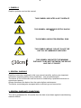
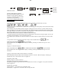
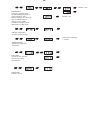
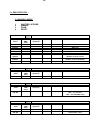
SCENA LED 150
User’s Manual rel. 1.0 GB
D.T.S. Illuminazione s.r.l. – ITALY
http://www.dts-lighting.it/
Made in Italy
2
Le informazioni contenute in questo documento sono state attentamente redatte e
controllate. Tuttavia non è assunta alcuna responsabilità per eventuali inesattezze.
Tutti i diritti sono riservati e questo documento non può essere copiato, fotocopiato,
riprodotto per intero o in parte senza previo consenso scritto della D.T.S .
D.T.S. si riserva il diritto di apportare senza preavviso cambiamenti e modifiche
estetiche , funzionali o di design a ciascun proprio prodotto. D.T.S non assume alcuna
responsabilità sull’uso o sull’applicazione dei prodotti o dei circuiti descritti.
The information contained in this publication has been carefully prepared and
checked. However, no responsibility will be taken for any errors. All rights are
reserved and this document cannot be copied, photocopied or reproduced, in part or
completely, without prior written consent from D.T.S.
D.T.S. reserves the right to make any aesthetic, functional or design modifications to
any of its products without prior notice. D.T.S. assumes no responsibility for the use or
application of the products or circuits described herein.
Les informations contenues dans le présent manuel ont été rédigées et contrôlées
avec le plus grand soin. Nous déclinons toutefois toute responsabilité en cas
d'éventuelles inexactitudes. Tous droits réservés. Ce document ne peut être copié,
photocopié ou reproduit, dans sa totalité ou partiellement, sans le consentement
préalable de D.T.S.
D.T.S. se réserve le droit d'apporter toutes modifications et améliorations esthétiques,
fonctionnelles ou de design, sans préavis, à chacun de ses produits. D.T.S. décline
toute responsabilité sur l'utilisation ou sur l'application des produits ou des circuits
décrits.
Las informaciones contenidas en este documento han sido cuidadosamente
redactadas y controladas. Con todo, no se asume ninguna responsabilidad por
eventuales inexactitudes. Todos los derechos han sido reservados y este documento
no puede ser copiado, fotocopiado o reproducido, total o parcialmente, sin previa
autorización escrita de D.T.S.
D.T.S. se reserva el derecho a aportar sin previo aviso cambios y modificaciones de
carácter estético, funcional o de diseño a cada producto suyo. D.T.S. no se asume
responsabilidad de ningún tipo sobre la utilización o sobre la aplicación de los
productos o de los circuitos descritos.
3
INDEX:
1- SYMBOLS
2- GENERAL WARNING
3- GENERAL WARRANTY CONDITION
4- TECHNICAL FEATURES
5- MAIN ELECTRICAL CHARACTERISTICS
6- ACCESSORIES
7- IMPORTANT SAFETY INFORMATION
7.1 Fire prevention
7.2 Prevention of electric shock
7.3 Safety
8- INPUT / OUTPUT CONNECTIONS
9- DMX SIGNAL CONNECTION
9.1 DMX Addresses
9.2 Selecting the DMX address
10- FIRMWARE UPDATING
11- DISPLAY FUNCTIONS
12- SERVICE MENU
13- DMX PROTOCOL
4
4
4
5
6
7
8
8
9
10
11
15
16
4
1- SYMBOLS
Graphic symbols used on this manual
THIS SYMBOL INDICATES A HOT SURFACE
THIS SYMBOL INDICATES ELECTRIC SHOCK
RISK
!
F
30cm
THIS SYMBOL INDICATES GENERAL RISK
THIS SYMBOL MEANS “DO NOT PLACE THE
UNIT ON INFLAMMABLE SURFACES”
THIS SYMBOL INDICATES THE MINIMUM
DISTANCE TO BE KEPT BETWEEN THE DEVICE
AND THE LIT OBJECT
2- GENERAL WARNING
Read the instruction contained in this user manual carefully, as they give important
information regarding safety during installation , use and maintenance.
The device is not for domestic use and must be installed by a qualified electrician or
experienced person.
Always disconnect the device from the mains before maintenance.
The device must always be equipped with an efficient ground connection.
3- GENERAL WARRANTY CONDITIONS
The unit is guaranteed for 36 months from the date of purchase against manufacturing
material defects.
5
4- TECHNICAL FEATURES
OVERVIEW
SCENA LED 150 is a compact, lightweight, DMX-controlled theatre projector featuring
a single high-power White LED (3.000 °K), a Ø 120 mm PC or Fresnel lens, and a
long wide excursion 8,2° - 70° (PC Version) or 12,8° - 62° (Fresnel Version) linear
motorized zoom with high-efficiency optical system, enabling it to be used as a PC
Beam or a very wide Wash.The unit is wireless ready.
SCENA LED 150 is a modern alternative to conventional theatre lights, improving light
quality, flexibility of use and installation, energy savings and component duration.
In fact the fixture doesn’t heat up, and the projection is always flicker free.
Also, the dimming curves are similar to those of halogen lamps.
The connectors are Powercon In & Out and 5 poles DMX In & Out.
SCENA LED 150 is contained in a strong housing with folded edges, designed to
resist all the rigours of continuous use.
Also, the yoke has an exclusive round flange + clutch system which guarantees a
perfect grip and safer operation.
PRODUCT CODES:
03.TS016.A
SCENA LED 150 *White 3.000 °K *PC BLACK
03.TS016.F
SCENA LED 150 *White 3.000 °K *FR BLACK
03.TS016.AWS
SCENA LED 150 *White 3.000 °K *With Wireless on Board *PC BLACK
03.TS016.FWS
SCENA LED 150 *White 3.000 °K *With Wireless on Board *FR BLACK
03.TS017.A
SCENA LED 150 *White 4.000 °K *PC BLACK
03.TS017.F
SCENA LED 150 *White 4.000 °K *FR BLACK
03.TS017.AWS
SCENA LED 150 *White 4.000 °K *With Wireless on Board *PC BLACK
03.TS017.FWS
SCENA LED 150 *White 4.000 °K *With Wireless on Board *FR BLACK
03.TS018.A
SCENA LED 150 *White 5.600 °K *PC BLACK
03.TS018.F
SCENA LED 150 *White 5.600 °K *FR BLACK
03.TS018.AWS
SCENA LED 150 *White 5.600 °K *With Wireless on Board *PC BLACK
03.TS018.FWS
SCENA LED 150 *White 5.600 °K *With Wireless on Board *FR BLACK
6
LED Technology
1 x White LED 3.000 °K, CRI>90, 7.000 Lumens
Also available as 4.000 °K and 5.600 °K LEDs
LED Max power: 150W
Optical group
Linear motorized zoom:
PC Version (Ø 120 mm PC lens) from min 8,2° (1.600 Lux at 5 mt)
to max 70° (185 Lux at 5 mt)
Fresnel Version (Ø 120 mm Fresnel lens) from min 12,8° (800 Lux at 5 mt)
to max 62° (250 Lux at 5 mt)
Control
4 DMX channels
LED display + 4 soft keys
Wireless ready
Connectors
Power supply: POWERCON IN & OUT Connector
DMX: 5 poles In & Out Connector
Power supply
Electronic full-range AC 90-260 V 50 / 60 Hz
5- MAIN ELECTRICAL CHARACTERISTICS
Input Voltage Range : Vin 90 - 260 Vac
Frequency : 50 / 60 Hz
Power Consumption Range : 5 - 160 W
Power Factor (Pf) : 0.95 electronic PFC controller
Efficiency : 95% typical
Control Input:
Control Signal : DMX 512
Dimming System : Constant Current PWM
Address Range : DMX 512 channels addressable by display
7
6- ACCESSORIES
As standard
1 x User’s Manual
1 x POWERCON male cable connector (D.T.S. Code: 0520P014)
1 x XLR 5 pins male cable connector (D.T.S. Code: 0508B028)
1 x XLR 5 pins female cable connector (D.T.S. Code: 0508B027)
1 x Filterframe for SCENA LED 150 *Black finish (D.T.S. Code: 02M00416.46)
Optional (on request)
* “C” Clamp G60 (Max. Load. 50 Kg) *Black finish (D.T.S. Code: 0521A004)
* “C” Clamp G60 (Max. Load. 50 Kg) *Chrome finish (D.T.S. Code: 0521A004.20)
* Barndoor for SCENA LED 150 *Black finish (D.T.S. Code: 03.TBD01)
* Ø 120 mm PC lens for SCENA LED 150 (D.T.S. Code: 0506P003)
* Ø 120 mm Fresnel lens for SCENA LED 150 (D.T.S. Code: 0506P004)
* Filterframe for SCENA LED 150 *Black finish (D.T.S. Code: 02M00416.46)
DIMENSIONS
Packing Dimensions
(LxWxH)
300 x 235 x 425 mm
Weight
5,3 Kg (PC version)
5,1 Kg (Fresnel version)
Weight
6,3 Kg (PC version)
6,1 Kg (Fresnel version)
185 mm
301 mm
Unit Dimensions
(LxWxH)
330 x 250 x 301 mm
250 mm
281 mm
330 mm
8
7- IMPORTANT SAFETY INFORMATION
7.1 Fire prevention:
Never locate the fixture on any flammable surface.
Minimum distance from flammable materials: 10 cm. F
Minimum distance from the closest illuminable surface: 30 cm. 30cm
Replace any blown or damaged fuses only with those of identical value (3,15 AT).
7.2 Prevention from electric shock:
High voltage is present inside the unit.
Unplug the unit prior to performing any operation which involves touching the inside of
the unit.
This equipment must be grounded, do not connect to non-grounded supplies.
The use of a thermal magnetic circuit breaker is recommended for each SCENA LED
150 unit.
Use only AC supplies 90-260V, 50 / 60 Hz.
SCENA LED 150 should never be located in position exposed to rain or in areas of
extreme humidity.
A good air ventilation is essential for proper equipment work.
!
7.3 Safety:
The external surface of the unit may exeed 50°C; never handle the unit until at least 5
minutes have elapsed since the unit was turned off.
Never install the unit in an enclosed area lacking sufficient air flow.
The ambient temperature should not exeed 40°C and should not be lower than -10°C.
8- INPUT / OUTPUT CONNECTIONS
DISPLAY PANEL
FUSE 3,15 AT
MAINS AC OUTPUT
90-260V 50/60 Hz
(MAX 14 SCENA LED 150 UNITS
@ 230V ;
MAX 7 SCENA LED 150 UNITS
@ 120V)
MAINS AC INPUT
90-260V 50/60 Hz
DMX IN
XLR 5 Pins Female
Panel Connector
DMX OUT
XLR 5 Pins Male
Panel Connector
9
9- DMX SIGNAL CONNECTION:
The unit operates using a digital DMX 512 signal.
Connection between the controller and the unit or between units must be carried out
using a two pair screened ø 0.5 mm.
Ensure that the conductors do not touch each other.
Do not connect the cable ground to the DMX connector chassis.
The plug housing must be isolated. Connect the mixer signal to the DMX IN projector
plug and connect it to the next projector by connecting the DMX OUT plug on the first
unit to the DMX IN plug of the second one.
In this way, all the projectors are cascade connected.
CONTROLLER
STANDARD
DMX 512
5
1
4
2
1=GND
2=DATA3=DATA+
3
DMX OUT
DMX IN
DMX OUT
DMX IN
DMX OUT
DMX IN
DMX OUT
If the display showing the DMX address flashes, then one of the following errors has
occurred:
- DMX signal not present
- DMX reception problem
For Installations where long distance DMX cable connections are needed, we
suggest to use a DMX terminator.
The DMX terminator is a male XLR 3-5 pins connector with a 120 ohm resistor
Between pin 2 and 3.
The DMX terminator must be plugged into the last unit (DMX out panel connector) of
the DMX line.
5
1
4
2
3
120 ohm
OUT
PLACE A 120 OHM RESISTOR BETWEEN PIN 2
AND 3 OF A MALE XRL CONNECTOR AND PLUG IT
INTO THE DMX OUT PANEL CONNECTOR OF THE
LAST UNIT CONNECTED TO THE DMX LINE
PIN 3
PIN 2
10
9.1 DMX addresses
SCENA LED 150 can be controlled with 4 DMX channels.
In order to use the unit in 4 channels, set the following addresses on the mixer:
Projector 1
Projector 2
Projector 3
….. A….
projector 6
A001
A005
A009
If you want to select the next projector, just add “4”
A021
9.2 Selecting the DMX address
1) Press the UP-DOWN key until you reach the required DMX address. The numbers
on the display will start to flash (but the new DMX address hasn't yet been set).
2) Press ENTER to confirm your selection. The numbers on the display will stop
flashing and the projector is now controlled by the new DMX address.
TIPS: if you keep pushed the UP or DOWN keys, the channels are calculated more
quickly and you get a faster selection.
2) Press ENTER to confirm your selection. The numbers on the display will stop
flashing and the projector is now controlled by the new DMX address.
10- FIRMWARE UPDATING
Warning:
This procedure require a base knowledge of Windows computer applications.
Please refer to an authorised D.T.S. service centre.
!
To update the software version of the SCENA LED 150 you need:
D.T.S. RED BOX interface (D.T.S. Code: 03.LA.008).
USB-DMX Driver for the D.T.S. RED BOX interface.
D.T.S. Firmware upgrade utility program.
(The driver and the installation procedure are available in our web site
www.dts-lighting.it)
Updating the software version.
Please follow the procedure below to perform the update:
1. Install the D.T.S. RED BOX USB-DMX driver on the PC you will use to update the
unit software.
2. Connect the D.T.S. RED BOX interface to the PC by using a USB cable.
3. Connect the D.T.S. RED BOX interface to the fixture by using a DMX cable.
4. Download the new software version into the unit by using D.T.S. Firmware upgrade
utility program.
11
11- DISPLAY FUNCTIONS
DISPLAY FUNCTIONS
The SCENA LED 150 display panel shows all the available functions . Using these
functions, it is possible to change some of the parameters and add some functions.
Changing the D.T.S. setting can vary the functions of the unit so that it does not
respond to the DMX 512 used to control it. Carefully follow the instructions below
before carrying out any variations or selections.
NOTE: the symbol
shows which key has to be pushed to obtain the desired
function.
Software version 1.13
MENU
Up-Down
ENTER
REVERSE DISPLAY
Reverses display's reading depending on
the mounting position (on the ground or
suspended).
Up-Down
Up-Down
ENTER
ENTER
Up-Down
Up-Down
DISPLAY STAND BY
To turn off the display (after 5 seconds)
Or leave it always on.
MENU
Up-Down
ENTER
Up-Down
ENTER
Up-Down
ENTER
DMX MODE
To select DMX mode : 4 DMX channels mode
(default) or Manual mode.
Manual mode can also be activated by pressing at
the same time the “UP’’ + ”DOWN” buttons on
unit display for 3 seconds (“A001”).
Floor
Position
Suspended
Position
Display
Off
Display
Always on
ENTER
ENTER
ENTER
ENTER
Default DMX Mode
4 Channels
ENTER
Manual Mode
12
MENU
Up-Down
ENTER
LED
Led Min/Max, Smooth, Compression,
Sync and Boost level values settings
Up-Down
Up-Down
Up-Down
LED MINIMUM VALUE
This menu allow to select the minimum
levels for white
Up-Down
Default = 0
ENTER
Default = 100
ENTER
ENTER
Up-Down
ENTER
Up-Down
Quadratic =
Linear light
output
Linear = Linear
Current output
LED MAXIMUM VALUE
This menu allow to select the maximum
levels for white
These settings have priority
on Master Dimmer channel
Range = Off-20
Default = 4
Up-Down
ENTER
Up-Down
Up-Down
ENTER
Up-Down
SMOOTH VALUE
This menu allow to select the value of
the delay (in milliseconds) for Dimmer
channel reaction to DMX or Program
variation.
Off = 25 ms. Instant response to DMX
variation.
20 = 250 ms. Smooth response to DMX
variation.
Boost mode
activated
Boost mode
deactivated
BOOST DRIVING
This menu allow to increase the LED’s
current from Min to Max
INFRARED MODE
Infrared remote control.
By activating Ir Mode, it will be
possible to navigate trought the unit
functions by using the D.T.S.
infrared remote control
(D.T.S. Code: 0514L008)
ENTER
ENTER
ENTER
ENTER
With BOOST active, the LED’S
current is set to Max value.
(30% more gain compared to
BOOST Off)
Default = Enabled
SYNC
This menu allow to adjust the PWM
frequency value (Hz) in order to reduce
flickering in the process of your camera
recordings
Up-Down
ENTER
Range = 610 Hz – 10
KHz
ENTER
Default = 610 Hz
COMPRESSION
This menu allow to select between
Linear current output or Quadratic
current output for LEDs
Default = Quadratic
MENU
ENTER
Up-Down
ENTER
ENTER
Note:
External infrared remote
sensor needed (D.T.S. Code:
03.LA.016)
NOT IMPLEMENTED ON SCENA LED 150
13
MENU
Up-Down
ENTER
Up-Down
ENTER
ENTER
Up-Down
WIRELESS DMX
Wireless DMX enabled / disabled.
By activating WDMX MODE, it will be
possible to control SCENA LED 150
via D.T.S. ANTENNA Wireless DMX
Transmitter (cod. 03.E1271).
Active only on SCENA LED 150 with
Wireless on board
ENTER
ENTER
Wireless
Enabled
Wireless
Disabled
UNLINK = LOG OUT
Logging on SCENA LED 150 (WIRELESS DMX must be enabled on SCENA LED 150 unit)
To log on the SCENA LED 150 in the WIRELESS system simply press and quickly release the function button
on the transmitter.
The transmitter will start flashing rapidly red/green scanning for new free receivers / SCENA LED 150 units.
When a SCENA LED 150 logs on to the transmitter the LINK green light on transmitter starts to flash rapidly.
After approximately 10 seconds the transmitter will jump back to normal mode and continue transmitting data.
The SCENA LED 150 now try to synchronize to the transmitter.
When synchronized to the transmitter, 2 different modes are possible:
1. Antenna transmitter has detected and transmits a DMX signal, in this mode a solid green light is seen on the
transmitter and solid display is seen on SCENA LED 150.
2. No DMX signal connected, the Antenna transmitter will flash red/green; display blinking on SCENA LED
150.
To log SCENA LED 150 off from a transmitter simply select UNLINK function
under
WIRELESS DMX MENU
and press ENTER.
When SCENA LED 150 is logged off, the display is blinking, meaning its available for log in on a new
transmitter.
Logging out a SCENA LED 150
Select UNLINK function
under WIRELESS DMX MENU
and press ENTER.
When SCENA LED 150 is logged off the display is blinking, meaning its available for log in on a new
transmitter.
Logging out all SCENA LED 150units linked to a transmitter
Press and hold the function button of the transmitter for about 3 seconds . When the display is blinking on
SCENA LED 150, it mean that the units are logged out.
Transmitter, Status LED
Flashing red/green, no dmx connected.
Solid green, dmx signal detected and transmitted.
Fast flashing red/green, log in mode (every free SCENA LED 150 unit, not logged in to any other transmitter,
will be logged on)
SCENA LED 150 Status
Display blinking = not logged on to a transmitter (free).
Solid display = logged on to a transmitter and receiving dmx data.
14
MENU
Up-Down
ENTER
Up-Down
ENTER
EMERGENCY
Emergency operating mode.
By setting Emergency mode, it
will be possible to select
Dimmer intensity level that will
then ran if DMX signal is
missing or not available.
Usefull for Emergency EXIT
ilumination on public areas.
MENU
Up-Down
ENTER
Up-Down
ENTER
ENTER
ENTER
Default = 255
ENTER
DEFAULT SETTING
To restore default settings
MENU
Up-Down
.
ENTER
ENTER
TEMPERATURE
Internal unit temperature
visualisation
MENU
Up-Down
ENTER
ENTER
Up-Down
LIFE TIME
This menu show the total
unit life time and the
LED life time
MENU
Up-Down
SOFTWARE
Software version
ENTER
ENTER
. .
Internal unit temperature
(° Celsius)
Default = OFF
15
12- SERVICE MENU
For technical personnel only
To operate this menu:
-Connect the unit to the main
-While reset is running, press the MENU and ENTER keys at the same time.
ENTER
ENTER
Up-Down
LENS
PC or Fresnel
lens selection
ENTER
ENTER
.
Up-Down
ENTER
CURRENT
From min 20 mA to max 600 mA
Default = 300 mA
ENTER
Up-Down
.
ENTER
.
ENTER
.
ENTER
ZERO OFFSET
From min 1 mm to max 50 mm
Default = 5 mm
ENTER
Up-Down
RANGE
From min 30 mm to max 150 mm
Default = 103 mm
ENTER
Up-Down
SPEED
Maximum speed
From min 1 mm/s to max 400 mm/s
Default = 20 mm/s
ENTER
Up-Down
.
ENTER
.
ENTER
ACCELERATION
Maximum Acceleration/Deceleration
From min 1 mm/s² to max 400 mm/s²
Default = 10 mm/s²
ENTER
Up-Down
RATIO
Transmission ratio.
From min 10 mm/turn to max 200 mm/turn
Default = 58.2 mm/turn
ENTER
ENTER
RESM
To restore service and user default
settings
ENTER
EXIT
Exit from service menu
16
13- DMX PROTOCOL
4 CHANNELS MODE
1
2
3
4
SHUTTER / STROBE
DIMMER
ZOOM
RESET
DMX CHANNEL
1
DMX range
Value
Mid Point
DMX
value
Parameter: SHUTTER / STROBE
Move Range
(degrees)
Mode
Option
000-009
010-019
020-029
030-119
120-149
150-179
Black-out
Open
Black-out
Strobe (from 3.27 s to 30 ms)
Pulse up (from 42.6 s to 120 ms)
Pulse down (from 42.6 s to 120 ms)
Random strobe
(Dimmer channel active)
Full independent Random Strobe
(Dimmer channel disabled)
Open
180-204
205-229
230-255
DMX CHANNEL
2
DMX range
Value
Mid Point
DMX
value
Parameter: DIMMER
Move Range
(degrees)
Mode
Option
000-255
3
DMX range
Value
Mid Point
DMX
value
Parameter: ZOOM
Move Range
(degrees)
Mode
Option
Function
Linear ZOOM from Narrow to Wide
(8,2° - 70° PC lens ;
12,8° - 62° FRESNEL lens)
000-255
DMX CHANNEL
4
DMX range
Value
Mid Point
DMX
value
016-255
Function
Proportional dimmer
DMX CHANNEL
000-015
Function
Parameter: RESET
Move Range
(degrees)
Mode
Option
Function
No Effect
Zoom Motor Reset
(active after 3 sec.)
17
NOTES
18
NOTES
19
NOTES
20
The information contained in this publication has been carefully prepared and
checked. However, no responsibility will be taken for any errors. All rights are reserved
and this document cannot be copied, photocopied or reproduced, in part or
completely, without prior written consent from D.T.S.
D.T.S. reserves the right to make any aesthetic, functional or design modifications to
any of its products without prior notice. D.T.S. assumes no responsibility for the use or
application of the products or circuits described herein.
MADE IN ITALY
ISO 9001:2008
D.T.S. quality system
is certified to the
ISO 9001:2008 standard
D.T.S. products are designed
and manufactured at the D.T.S.
plants in italy
0517I197
0517I197
D.T.S. Illuminazione s.r.l. – Via Fagnano Selve 10-12-14 47843
Misano Adriatico (RN) Italia
Tel.: +39 0541 611131. Fax + 39 0541 611111
[email protected] www.dts-lighting.it