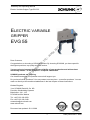
1
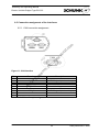
Assembly and Operating Manual
Electric Variable Gripper Type EVG 55
ELECTRIC VARIABLE
GRIPPER
c.
w
w
w
.a
i
ro
il.
co
m
EVG 55
s,
In
Dear Customer,
st
em
Congratulations on choosing a SCHUNK product. By choosing SCHUNK, you have opted for
the highest precision, top quality and best service.
il
Sy
You are going to increase the process reliability of your production and achieve best
machining results – to the customer's complete satisfaction.
Ai
r-O
SCHUNK products are inspiring.
Our detailed assembly and operation manual will support you.
Do you have further questions? You may contact us at any time – even after purchase. You can
reach us directly at the mentioned addresses in the last chapter of these instructions.
Kindest Regards,
Your SCHUNK GmbH & Co. KG
Precision Workholding Systems
Bahnhofstr. 106 - 134
D-74348 Lauffen/ Neckar
Tel. +49-7133-103-2503
Fax +49-7133-103-2189
[email protected]
www.schunk.com
Document last updated: 20.11.2008
1
Date printed 20.11.2008
Assembly and Operating Manual
Electric Variable Gripper Type EVG 55
Contents
SAFETY................................................................................................................................................. 4 1.1 EXPLANATION OF SYMBOLS .............................................................................................................. 4 1.2 INTENDED USE ................................................................................................................................. 4 1.3 UNINTENDED USE............................................................................................................................. 4 1.4 ENVIRONMENTAL AND OPERATING CONDITIONS .................................................................................. 4 1.5 SAFETY INFORMATION ...................................................................................................................... 5 2 WARRANTY .......................................................................................................................................... 8 3 SCOPE OF DELIVERY ......................................................................................................................... 8 4 TECHNICAL DATA ............................................................................................................................... 9 4.1 BASIC DATA ..................................................................................................................................... 9 4.2 FACTORY SETTINGS OF ALL MODULES............................................................................................... 9 4.3 GRIPPING FORCE DIAGRAMS ........................................................................................................... 10 5 DESCRIPTION OF THE MODULE ..................................................................................................... 11 5.1 DESIGN OF THE MODULE ................................................................................................................. 11 5.2 OPERATING PRINCIPLE ................................................................................................................... 12 5.3 INFORMATION ON CONTROLLER MCS-06 ........................................................................................ 13 5.3.1 DVD ..................................................................................................................................... 13 5.3.2 Technical data for MCS-06 .................................................................................................. 13 5.3.3 Layout of the MCS-06 controller .......................................................................................... 14 6 ASSEMBLY ......................................................................................................................................... 15 6.1 MECHANICAL CONNECTION ............................................................................................................ 15 6.2 ASSEMBLY ..................................................................................................................................... 16 6.3 SPECIAL CONNECTION DIMENSIONS ................................................................................................. 17 6.4 MCS-06 ELECTRICAL CONNECTION................................................................................................. 18 6.4.1 Notes ................................................................................................................................... 18 6.4.2 Connection principle ............................................................................................................ 18 6.4.1 Power supply requirements ................................................................................................. 18 6.4.2 EMV fitting for the connection cable on the gripper............................................................. 19 6.4.3 Connection assignment at X1 terminal ........................................................................... 22 6.4.4 Connection assignment at X2 terminal ........................................................................... 23 6.4.5 Connection assignment at X3 terminal ................................................................................ 24 6.4.6 Connection assignment at X4 terminal ................................................................................ 25 6.5 CONNECTION ASSIGNMENT OF THE INTERFACES .............................................................................. 26 6.5.1 CAN connection assignment ............................................................................................... 26 6.5.2 PROFIBUS connection assignment .................................................................................... 27 6.5.3 RS232 connection assignment ............................................................................................ 28 7 FUNCTION AND HANDLING ............................................................................................................. 29 7.1 PRE-POSITIONING .......................................................................................................................... 30 7.2 EXAMPLE OF AN OPTIMIZED GRIPPING PROCEDURE .......................................................................... 30 8 SYSTEM INTEGRATION OF THE UNIT ............................................................................................ 31 8.1 NOTES .......................................................................................................................................... 31 8.2 SYSTEM STRUCTURE ...................................................................................................................... 31 8.3 SCHUNK MOTION-PROTOCOL ....................................................................................................... 32 8.4 OVERVIEW OF SELECTED COMMANDS AND MESSAGES ...................................................................... 33 8.4.1 Commands for the module .................................................................................................. 33 8.4.2 GET_STATE ........................................................................................................................ 34 8.4.3 Responses (Acknowledge) or spontaneous essage from module ...................................... 34 8.4.4 Error messages from the module ........................................................................................ 34 9 EXAMPLES FOR DATA EXCHANGE BETWEEN MASTER CONTROLLER AND GRIPPER ........ 35 9.1 APPLICATION EXAMPLE FOR RS232 ................................................................................................ 35 9.1.1 Referece run ........................................................................................................................ 35 Ai
r-O
il
Sy
st
em
s,
In
c.
w
w
w
.a
i
ro
il.
co
m
1 2
Date printed 20.11.2008
Assembly and Operating Manual
Electric Variable Gripper Type EVG 55
9.1.2 Position run .......................................................................................................................... 36 9.1.3 Acknowledgment of an error message ................................................................................ 36 9.2 APPLICATION EXAMPLE FOR CAN ................................................................................................... 37 9.2.1 Reference run ...................................................................................................................... 37 9.2.2 Position run .......................................................................................................................... 38 9.2.3 Acknowledgment of an error message ................................................................................ 38 9.3 APPLICATION EXAMPLE FOR PROFIBUS DP ...................................................................................... 39 9.3.1 Reference run ...................................................................................................................... 39 9.3.2 Position run .......................................................................................................................... 40 9.3.3 Acknowledgment of an error message ................................................................................ 41 10 TROUBLESHOOTING ........................................................................................................................ 42 11 REPLACEMENT OF THE MODULE .................................................................................................. 43 m
12 COMPLETELY REMOVING A UNIT FROM THE MACHINE ............................................................ 43 .a
i
ro
il.
co
13 MAINTENANCE AND CARE .............................................................................................................. 44 13.1 CLEANING...................................................................................................................................... 44 13.1.1 Gripper ................................................................................................................................. 44 13.1.1 Controller ............................................................................................................................. 44 13.2 LUBRICATION ................................................................................................................................. 45 w
14 DISASSEMBLY OF THE MODULE .................................................................................................... 45 Ai
r-O
il
Sy
st
em
s,
In
c.
w
w
15 CONTACT ........................................................................................................................................... 46 3
Date printed 20.11.2008
Assembly and Operating Manual
Electric Variable Gripper Type EVG 55
1. Safety
1.1. Explanation of symbols
This symbol is displayed wherever there is a possibility of danger to life and limb.
This symbol is displayed wherever there is a possibility of damage to the unit exists.
m
This symbol denotes important information about the product and its handling.
co
1.2. Intended use
.a
i
ro
il.
The gripper unit is designed for gripping and temporary secure holding of workpieces or other
objects.
w
w
w
The unit is intended for installation / mounting in machines and equipment. The requirements of
the applicable directives must be observed and complied with.
s,
In
c.
The unit may be used only within the range of its technical data. Any other use is deemed improper and unintended use. The manufacturer will not be liable for any damages resulting from
improper use.
il
Sy
st
em
To use this unit as intended, it is also essential to comply with the manufacturer's specifications
regarding commissioning, assembly, operation, maintenance and the ambient conditions. Any
other use or use exceeding that specified is an infringement of use for intended purpose. The
manufacturer shall not be liable for any damages arising from use other than the intended use.
Ai
r-O
1.3. Unintended use
If the unit is used directly as a guide or bracket for tools such as lasers, drills, milling machines,
etc., this is deemed misuse. Likewise, the gripper is not a pressing tool.
This means that all actions that deviate from the functions of gripping, holding and releasing of a
gripped object are deemed misuse.
1.4. Environmental and operating conditions
-
-
-
Use the unit only within the application parameters defined in the Technical Catalog.
The most recent version applies (according to Chapter 2.3 of the General Terms
and Conditions).
Clean ambient conditions at room temperature are required. If these conditions
are not ensured, the maintenance interval will be shorter, depending on the actual
utilization.
The environment must be free of splashing water and vapors, and also of abrasive
dust and process dust. This does not apply to units designed especially for unclean
environments.
4
Date printed 20.11.2008
Assembly and Operating Manual
Electric Variable Gripper Type EVG 55
1.5. Safety information
There are potential risks associated with the unit, for example if:
the gripper is improperly used, installed or serviced.
the gripper is used other than for the intended purpose.
the EC Machine Directive, the accident prevention regulations, the VDE
guidelines or the safety and installation instructions are not observed.
2.
All personnel who are responsible for installation, commissioning and servicing
must have read and understood the entire operating manual, in particular the
chapter on »Safety«. It is recommended to have this confirmed in writing.
3.
Installation and dismantling, mounting of the proximity switches, connections and
commissioning may be carried out only by authorized personnel.
4.
Dangers exist due to units automatically starting up!
Do not reach into the open mechanical parts and the area between the
gripper fingers.
Do not move any parts by hand when the unit is connected to the power
supply.
Remove the power supply cables for assembly, modification,
maintenance and adjustment of the unit.
5.
During connection, adjusting, commissioning and testing, measures must be taken
to prevent the risk of inadvertent activation of the unit by the fitter / installer or other
persons.
6.
There is a danger due to falling or ejected objects!
Take preventive measures to prevent the falling or ejection of potentially
dangerous objects (machined workpieces, tools, chips, debris, waste,
etc.).
7.
During operation dangers can be caused by the gripper due to:
moving or rotating parts
or hot surfaces – up to 110°C!
Ai
r-O
il
Sy
st
em
s,
In
c.
w
w
w
.a
i
ro
il.
co
m
1.
Therefore, suitable protective measures such as protective covers must be
provided in accordance with the EC Machine Directive.
8.
The electric gripper is not suitable for use in potentially explosive areas.
If the gripper is to be used in special applications (e.g. potentially explosive areas),
always comply with the required standards and regulations (e.g. EN 50014 and EN
50018).
The approval for such special areas of application must always be obtained from
Schunk in writing.
9.
The correct operation of the unit can be disrupted by contamination or running dry!
Observe the maintenance and cleaning intervals.
10.
Ensure compliance with EMC directives when connecting the motor and the
controller.
5
Date printed 20.11.2008
Assembly and Operating Manual
Electric Variable Gripper Type EVG 55
The gripper is equipped with an electric drive.
Serious injuries and major damages can be prevented by:
Assignment of only qualified personnel for all work on/with the unit!
(Personnel who are familiar with electric drive systems and with the
installation, assembly, commissioning and operation of electric drives.)
Compliance with the applicable national accident prevention regulations
etc. Cp. IEC 364 and CENELEC HD 384 or DIN VDE 0100 and IECReport 664 or VDE 0110 and national accident prevention regulations or
VBG 4.)
During transport and handling, make sure that no components are bent
and that no insulation clearances are changed. (Electric grippers contain
electrostatically sensitive components.)
Establish all electrical connections in accordance with the information in
this documentation and the relevant regulations (e.g. wire size, fuses,
protective conductors).
12.
Repairs in and on the electric gripper may be carried out only by the manufacturer
or an authorized repair center.
Unauthorized opening and improper handling can result in bodily injury and
material damage.
13.
Electronic devices are not fail-safe. The user is personally responsible for ensuring
that the drive is in a safe state in the event of a failure.
14.
Additional bore holes, threads or attachments not offered by SCHUNK as
accessories may be mounted only after obtaining the approval of SCHUNK.
15.
In addition, the applicable safety regulations and accident prevention regulations
must be observed.
16.
Danger of personal injury or material damage.
Faulty position parameters can lead to crushing, jamming or breakage of the attachments.
Always adjust parameter specifications to the unit's operating environment.
Only specialist personnel or specially trained staff should carry out settings and enter parameters.
Ai
r-O
il
Sy
st
em
s,
In
c.
w
w
w
.a
i
ro
il.
co
m
11.
6
Date printed 20.11.2008
Assembly and Operating Manual
Electric Variable Gripper Type EVG 55
Attachments can fall if the fittings or alterations to the machine or system are faulty.
Serious bodily harm possible (e.g. laceration of the head) with fatal consequences.
Check for compliance with EC Machine Directive item 1.4 for the safety
requirements.
(Check need for barriers etc.)
Only allow specialist personnel or specially trained staff to handle the
machine / system.
Follow the assembly instructions.
Wear appropriate protective clothing (e.g. helmet).
18.
Contamination or dry-running can lead to malfunctions.
Fatal head injuries can be caused by workpieces falling or being flung off.
Comply with the maintenance and cleaning intervals.
Restrict access to the module's operating area.
Wear appropriate protective equipment (e.g. helmet).
.a
i
ro
il.
co
m
17.
Ai
r-O
il
Sy
st
em
s,
In
c.
w
w
w
Note
The CD-ROM for older versions of the unit includes a different
configuration tool (PowerConfig).
If you wish to use the older version, please contact your SCHUNK contact
person.
7
Date printed 20.11.2008
Assembly and Operating Manual
Electric Variable Gripper Type EVG 55
2. Warranty
The warranty period is 24 months from the date of delivery when utilized as intended in singleshift operations and in compliance with the specified maintenance and lubrication intervals.
Parts that come into contact with the workpiece and wearing parts are not covered by the warranty. See also our General Terms and Conditions in this regard.
The unit is considered defective when the basic gripping function is inoperable.
co
m
3. Scope of delivery
w
w
.a
i
ro
il.
The scope of delivery includes:
- Electric Variable Gripper EVG (without top jaws) in the ordered model.
- Assembly and Operating Manual EVG
- DVD (Included only in the delivery of the optional external Controller MCS-12)
- USBtoRS232- Converter incl. Driver-CD
In
c.
w
Note
For optimum use of your SCHUNK gripper, the SCHUNK controller
MCS-06 is recommended. The controller can be ordered separately.
Ai
r-O
il
Sy
st
em
s,
Other accessories for the unit are available in the SCHUNK catalog, at
www.schunk.com or from your SCHUNK contact person.
8
Date printed 20.11.2008
Assembly and Operating Manual
Electric Variable Gripper Type EVG 55
4. Technical Data
4.1. Basic data
The noise level emitted by the unit is ≤ 70dB(A)
m
Note
Additional technical data can be found in our catalog. The most recent version applies.
(according to Terms and Conditions in Chapter 2.3)
ro
.a
i
w
w
w
In
s,
st
em
Sy
il
Ai
r-O
EVG 55 stroke 100
50 mm
57 N
3N
0,28 kg
1,5s
1,5s
1,1 kg
18,7 kg cm²
± 0,05 mm
125 mm
24 VDC
3,7 Aeff
8 Aeff
400 mm/s
10000 mm/s²
2,37
2000
il.
EVG 55 stroke 40
20 mm
24 N
5N
0,12 kg
0,6s
0,6s
0,79 kg
8,98 kg cm²
± 0,05 mm
125 mm
24 VDC
3,6 Aeff
8 Aeff
300 mm/s
10000 mm/s²
2,37
2000
c.
Designation
Stroke per finger
Max. gripping force bei I=8 Aeff * / 80% ED
Min. gripping force
Workpiece weight **
Öpening time
Closing time
Deadweight
Mass moment of inertia ly
Repeat accuracy ***
Max. finger length
Power supply for MCS-06
Rated current
Max. current
Max. speed
Max. acceleration
Gear reduction
Impulse encoder per revolution
co
The technical dimensions of the gripper can be found in the catalog data.
Table 1: Basic data
* The gripping force is the arithmetic sum of the individual forces acting on the gripper jaws at a distance of P=50 mm where I=8
Aeff =80% duty ratio and 6 mm pre-positioning and max. speed, Mmax < 3 seconds
** Values for friction coefficient µ = 0.1 and safety factor v = 2. The values can be increased in the case of form-fitting.
*** Distribution of the end positions with 100 successive strokes.
4.2. Factory settings of all modules
DEFAULT values
Communication
Data rate
Module address
RS232
9,600 Baud
12
9
Date printed 20.11.2008
Assembly and Operating Manual
Electric Variable Gripper Type EVG 55
Ai
r-O
il
Sy
st
em
s,
In
c.
w
w
w
.a
i
ro
il.
co
m
4.3. Gripping force diagrams
10
Date printed 20.11.2008
Assembly and Operating Manual
Electric Variable Gripper Type EVG 55
5. Description of the module
5.1. Design of the module
The gripper base jaws are designed so that many different types of fingers for parallel grippers
can be mounted. The gripper is provided with power via a controller. The gripper only has to be
connected to the controller.
il.
co
m
The module is equipped with a brushless direct current servo motor with bevel gears and toothed belt.
The gripper can also use a magnetic brake that catches immediately in the event of a loss of
current.
w
w
w
.a
i
ro
The unit is designed to grip, hold and release workpieces.
The servo-electric gripper has a software safety system for monitoring the end positions, voltage, current and temperature, with a function for switching off the unit if any of the permitted values are exceeded.
Ai
r-O
il
Sy
st
em
s,
In
c.
All the parameters, such as speed, stroke, position or motor current, are transferred to an external controller via the corresponding interface (RS 232, CAN Bus, Profibus).
11
Date printed 20.11.2008
Assembly and Operating Manual
Electric Variable Gripper Type EVG 55
5.2. Operating principle
For optimum use of your SCHUNK gripper, the SCHUNK controller
MCS-06 is recommended. The controller can be ordered separately..
The actuator (the brushless DC servo motor with resolver) is controlled by the external (logic)
controller. This controller receives the required parameters from the master controller.
m
The motion sequences of the gripper are linear. The gripper jaws execute a mechanical motion. Their position is monitored constantly. The required data is transmitted by sensors back to
the external logic controller.
Ai
r-O
il
Sy
st
em
s,
In
c.
w
w
w
.a
i
ro
il.
co
The gripper is controlled via the user interface, where the required data is transmitted via the
external logic controller. You can define the following parameters, for example:
Current i;
Gripper jaw position (=distance between base jaws);
Speed v;
Acceleration a.
12
Date printed 20.11.2008
Assembly and Operating Manual
Electric Variable Gripper Type EVG 55
5.3. Information on Controller MCS-06
5.3.1. DVD
The DVD is included in the delivery of the MCS-12.
m
Content of DVD:
MC Demo (configuration tool and commissioning tool)
Operating manual in PDF format
Software manual SCHUNK MotionControl in PDF format
co
5.3.2. Technical data for MCS-06
.a
i
ro
il.
A controller is needed to operate the gripper.
We recommend the MCS-06.
Value / characteristics
0 306 030
Profibus DP (auto-detect),
RS232 (9.600 Baud)
CAN
24 V DC
6A
0,45 kg
Current regulation
Speed regulation
Position regulation
w
w
Designation
MCS-06 Id number
st
em
s,
In
c.
Output power supply
Rated current
Mass
w
Interfaces = communication type (data rate)
Sy
Control types
Ai
r-O
il
Table 2: Controller MCS-06 Data
13
Date printed 20.11.2008
Assembly and Operating Manual
Electric Variable Gripper Type EVG 55
In
c.
Figure 1: Layout of the MCS-06 controller
w
w
w
.a
i
ro
il.
co
m
5.3.3. Layout of the MCS-06 controller
Type MCS-06
Display LED for POW
(displays available output power supply)
/2/ Display LED for RDY
(displays communication readiness)
/3/ Display LED for ERR
(displays occurring errors)
/4/ Terminal strip X1 for motor phases
/5/ Terminal strip X2 for encoder, Hall-effect sensors, resolver,
power supply +5 VDC for encoder, resolver and Hall-effect sensors
/6/ Terminal strip X3 for digital inputs and outputs, encoder,
power supply +24 VDC for logic
/7/ Terminal strip X4 for power supply +24 VDC for output
/8/ RS232 connection
/9/ CAN connection
/10/ Profibus connection
Ai
r-O
il
Sy
st
em
s,
/1/
Table 3: Controller MCS-06 terminals and display elements
14
Date printed 20.11.2008
Assembly and Operating Manual
Electric Variable Gripper Type EVG 55
6. Assembly
6.1. Mechanical Connection
co
m
Danger!
Falling parts as a result of incorrect modifications and attachments to the machine or
system! Fatal head injuries (e.g. lacerations) or server bodily injuries (e.g. contusions)
are possible!
Leave power switched off until all mounting work has been completed.
Have mounting work carried out only by qualified or specially trained personnel.
Wear proper protective gear (e.g. safety helmet).
il.
Also observe the safety information on page 4.
In
c.
w
w
w
.a
i
ro
Mount the unit so that:
The connection cable does not present a hazard to personnel or the machine.
(e.g.: prevent malfunctions by winding up the cable!)
Personnel and the machine are not exposed to hazards.
(e.g.: prevent crushing between machine parts;
prevent collisions of machine parts!)
Ai
r-O
il
Sy
st
em
s,
Requirements for levelness of the bolting surface
(in relation to the entire bolting surface for the gripper)
< 0.02 mm for an edge length up to 100 mm
< 0.05 mm for an edge length of 100 mm or more
15
Date printed 20.11.2008
Assembly and Operating Manual
Electric Variable Gripper Type EVG 55
.a
i
ro
il.
co
m
6.2. Assembly
w
w
Figure 2: Mechanical connection
In
c.
w
The gripper can be fastened and mounted using the threads at the sides (including centering)
available for that purpose. A further option is an adaptation via an L-shaped adapter plate with
ISO 9409-1-A50 flange.
Ai
r-O
il
Sy
Table 4: EVG mounting
st
em
s,
Type EVG 55
/11/ L-shaped adapter plate with flange as per ISO 9409-1-A50
/12/ DIN EN ISO 4762 M4 mounting screws and centering sleeve ∅6x5.35
16
Date printed 20.11.2008
Assembly and Operating Manual
Electric Variable Gripper Type EVG 55
6.3. Special connection dimensions
The EVG gripper can be screwed on using the lateral M4 mounting threads. Two M3 mounting
threads for the top jaws are available on each base jaw.
il.
co
m
for bore hole
±0.1 for mounting thread M3
.a
i
w
w
w
c.
In
s,
Ai
r-O
il
Sy
st
em
for bore hole
±0.1 for mounting thread M4
ro
for bore hole
±0.1 for mounting thread M4
Figure 3: Connection dimensions
17
Date printed 20.11.2008
Assembly and Operating Manual
Electric Variable Gripper Type EVG 55
6.4. MCS-06 electrical connection
6.4.1. Notes
Observe the safety information in the standard "Electrical Equipment for Machines"
(DIN EN 60204).
co
m
Commissioning is permitted only on the condition of compliance with ECM guidelines
(89/336/EEC). For the Low-Voltage Directive 73/23/EEC, the harmonized standards of
the series prEN 50178/DIN VDE 0160 apply for the grippers in combination with
EN 60439-1/DIN VDE 0660 Part 500 and EN 60146/DIN VDE 0558.
.a
i
ro
il.
6.4.2. Connection principle
w
w
w
The gripper is supplied with power via the controller. The gripper has to be connected to the
controller.
Ai
r-O
il
Sy
st
em
s,
In
c.
Danger of short circuit!
The printed circuit board of the gripper or of the MCS-12 controller could be destroyed!
Due to incorrect connection of the power supply.
Note layout of the terminals.
6.4.1. Power supply requirements
Power supply (MCS-06)
Power supply for logic controller
Motor power supply (module)
Connected load
Voltage ripple at output
24 V DC
24 V DC (bis 36 V DC)
24 V (+ 10% / - 4%)
Number of modules x module nominal current x 1.2
Residual ripple less than 150 mVSS;
Switching peaks less than 240 mVSS
Table 5: Power supply requirements
18
Date printed 20.11.2008
Assembly and Operating Manual
Electric Variable Gripper Type EVG 55
6.4.2. EMV fitting for the connection cable on the gripper
Sy
st
em
s,
In
c.
w
w
w
.a
i
ro
il.
co
m
The EVG gripper has a connection board to which the signal lines and output lines for the
MCS-06 controller can be connected. To remove the cover, loosen the countersunk screws.
The connection cable is pulled through the EMV fitting.
Ai
r-O
il
Figure 4: Connection board with terminals on the EVG
Figure 5: Terminal pin assignment on the EVG
19
Date printed 20.11.2008
Assembly and Operating Manual
Electric Variable Gripper Type EVG 55
Function
Cable color
(for Schunk cables)
-
il.
co
m
Brown (0.34 mm²)
White (0.34 mm²)
Yellow
Pink
Gray
Black
White
Copper
Purple
Brown
Orange
Blue
Red
Gray
Black
Gray
Black
w
w
w
.a
i
ro
Brake Brake +
Hall sensor 1
Hall sensor 2
Hall sensor 3
Encoder track A
Encoder track B
Encoder track C
Encoder track A\
Encoder track B\
Encoder track C\
GND
+5V
Shielding
Motor phase W
Shielding
Motor phase W
Encoder track C\
Encoder track B\
Encoder track A\
Encoder track C
Encoder track B
Encoder track A
GND
+5V
Hall sensor 3
Hall sensor 2
Hall sensor 1
GND
+5V
Motor phase U
Motor phase V
Motor phase U
Motor phase V
Brake +
Brake -
c.
Pin assignment
/13/ EMV fitting
/14/ Cover
/15/ Board with terminals
/16/ Countersunk screws
/17/ X5 terminal strip
1
2
3
4
5
6
7
8
9
10
11
12
13
/18/ X6 terminal strip
1
2
/19/ X7 terminal strip
1
2
/20/ X8 connector
1
2
3
4
5
6
7
8
9
10
11
12
13
14
15
16
17
18
19
20
/21/ X9 terminal strip
1
2
/22/ X10 terminal strip
1
2
/23/ X23 connector
1
2
Table 6: Terminal pin assignment
Ai
r-O
il
Sy
st
em
s,
In
Type EVG 55
20
Red
White
Red
White
Date printed 20.11.2008
Assembly and Operating Manual
Electric Variable Gripper Type EVG 55
Caution
Incorrect wire insulation can lead to a short-circuit in the board.
Can lead to malfunctions or destruction of the board.
All electrical connection work to be carried out by appropriate specialist personnel only.
Do no remove too much insulation from the wire strands.
Do not connect the wires incorrectly.
Lead the connection cable through the EMV fitting.
Insulate approx. 90 mm of the MCS-06's connecting cable outer cover. Insulate
approx. 5 mm of the individual wires in a manner suitable for the spring clamp
connectors.
The external cable shielding is connected to the EMV fitting. To do this, pull back the
external shielding over the cable's outer cover.
Fix the shielding in position using suitable shrink tubing, so that the shielding remains
visible at the end of the cover.
w
w
Connecting cable
EMC fitting
Outer shield
Ai
r-O
il
Sy
st
em
s,
In
c.
-
w
-
.a
i
ro
-
il.
-
co
m
Caution
Overtightening the fastening screws can lead to the board breaking.
Can lead to malfunctions or destruction of the board.
Tighten the screws only slightly – the board is merely fixed in place.
Stranded wires
Heat-shrinkable sleeve
Figure 6 EMC fitting
21
Date printed 20.11.2008
Assembly and Operating Manual
Electric Variable Gripper Type EVG 55
6.4.3. Connection assignment at X1 terminal
st
em
s,
In
c.
w
w
w
.a
i
ro
il.
co
m
Note
The cable color refers to the pre-installed SCHUNK connection cable.
You require the strands with a diameter of 1,0 mm2 here.
Sy
Figure 7: X1 terminal
Ai
r-O
il
Pin
Function
1
Motor phase U
2
Motor phase V
3
Motor phase W
4
Shielding
Table 7: X1 terminal pin assignment
Cable color
Red
White
Black
22
Date printed 20.11.2008
Assembly and Operating Manual
Electric Variable Gripper Type EVG 55
6.4.4. Connection assignment at X2 terminal
st
em
s,
In
c.
w
w
w
.a
i
ro
il.
co
m
Note
The cable color refers to the pre-installed SCHUNK connection cable.
You require the strands with a diameter of 0.15 mm2 here.
il
Pin Function
Sy
Figure 8: X2 terminal
Ai
r-O
1 Resolver signal reference +
2 Resolver signal COSINE+
3 Resolver signal COSINE4 Resolver signal SINE+
5 Resolver signal SINE6 Encoder track A (or Adiff)
7 Encoder track B (or Bdiff)
8 Encoder track C (or Adiff\)
9 +5V for encoder and Hall sensors
10 GND for encoder and Hall sensors
11 Hall sensor 1
12 Hall sensor 2
13 Hall sensor 3
14 Brake 15 Brake +
16 Resolver signal reference Table 8: X2 terminal pin assignment
Cable color
(diff. encoder)
Black
White
Purple
Red
Blue
Yellow
Pink
Gray
Brown (0.34 mm²)
White (0.34 mm²)
-
23
Date printed 20.11.2008
Assembly and Operating Manual
Electric Variable Gripper Type EVG 55
6.4.5. Connection assignment at X3 terminal
st
em
s,
In
c.
w
w
w
.a
i
ro
il.
co
m
Note
The cable color refers to the pre-installed SCHUNK connection cable.
You require the strands with a diameter of 0.15 mm2 here.
Function
il
Pin
Sy
Figure 9: X3 terminal
Ai
r-O
1 Encoder track Bdiff\
2 Encoder track Cdiff
3 Encoder track Cdiff\
4 Digital output 1
5 Digital output 2
6 Digital output 3
7 Digital output 4
8 +24V logic supply
9 GND logic supply
10 Digital input 4
11 Digital input 3
12 Digital input 2
13 Digital input 1
14 Default
Table 9: X3 terminal pin assignment
Cable color
(diff. encoder)
Brown
Copper
Orange
-
24
Date printed 20.11.2008
Assembly and Operating Manual
Electric Variable Gripper Type EVG 55
w
w
w
.a
i
ro
il.
co
m
6.4.6. Connection assignment at X4 terminal
Ai
r-O
il
Sy
st
em
s,
Pin
Function
1
+24V output supply
2
GND output supply
3
PE protective conductor
Table 10: X4 terminal pin assignment
In
c.
Figure 10: X4 terminal
25
Date printed 20.11.2008
Assembly and Operating Manual
Electric Variable Gripper Type EVG 55
6.5. Connection assignment of the interfaces
st
em
Figure 11: CAN interface
s,
In
c.
w
w
w
.a
i
ro
il.
co
m
6.5.1. CAN connection assignment
Ai
r-O
il
Sy
Pin
Function
Description
1
2
CAN_L
CAN BUS signal (dominant low)
3
4
5
CAN_SHLD
Optional shielding
6
7
CAN_H
CAN BUS signal (dominant high)
8
9
Table 11: CAN interface pin assignment
26
Date printed 20.11.2008
Assembly and Operating Manual
Electric Variable Gripper Type EVG 55
w
w
w
.a
i
ro
il.
co
m
6.5.2. PROFIBUS connection assignment
In
c.
Figure 12: PROFIBUS interface
Ai
r-O
il
Sy
st
em
s,
Pin
Function
Description
1
2
3
RxD/TxD-P
Received/transmitted data plus line (B line)
4
5
GND
Reference potential for 5V supply voltage
6
+5 V
Supply voltage +5 V DC
7
8
RxD/TxD-N
Received/transmitted data N line (A line)
9
Table 12: PROFIBUS interface pin assignment
27
Date printed 20.11.2008
Assembly and Operating Manual
Electric Variable Gripper Type EVG 55
c.
w
w
w
.a
i
ro
il.
co
m
6.5.3. RS232 connection assignment
s,
In
Figure 13: RS232 interface
Ai
r-O
il
Sy
st
em
Pin
Function
Description
1
2
TxD
Transmitted data
3
RxD
Received data
4
5
GND
Reference potential for data lines
6
7
8
9
Table 13: RS232 interface pin assignment
28
Date printed 20.11.2008
Assembly and Operating Manual
Electric Variable Gripper Type EVG 55
7. Function and handling
Important!
Gripper base jaws can become blocked by accumulations on the toothed belt.
Sustained short stroke travel can damage the gripper.
Travel the entire stroke every 1000 cycles (or at least once a day).
co
m
Attention!
After every start up, the Controller MCS06 has to search his commutation-offset.
Therefore the gripper has to move an entire stroke.
Ai
r-O
il
Sy
st
em
s,
In
c.
w
w
w
.a
i
ro
il.
The servo axis of the gripper normally moves as if hitting a mechanical stop. Therefore, the following points must be observed when handling the unit:
The maximum gripper force refers to the load on the guides.
Therefore, this force must not be built up until shortly before the workpiece.
When the gripper travels in current mode the fingers accelerate. If gripping takes place
at this point the fingers will be subject to the following forces:
a) increased gripping force proportional to the current
b) increased pulse proportional to the speed on impact; the impact speed
should be kept as low as possible. This can be achieved by pre-positioning.
If the gripper moves to the stop (even when gripping!) in positioning mode it will cause
mechanical overload. This will reduce the gripper’s service life.
Use the magnetic brake (if installed) only when the fingers are idle.
Check the lubrication of the guides at regular intervals; especially constant, very small
strokes can lead to dry-running.
Note
If the gripper travels in live mode, the gripper fingers accelerate.
The gripping forces acts on the gripper fingers when the gripping procedure starts.
This force is proportional to the current. In other words, the larger the current, the
larger the gripping force.
The maximum permissible gripping force is achieved with the maximum permissible
current (see technical data, page 9)
29
Date printed 20.11.2008
Assembly and Operating Manual
Electric Variable Gripper Type EVG 55
7.1. Pre-positioning
w
w
w
.a
i
ro
il.
co
m
When gripping the workpiece, it is important to ensure that pre-positioning is carried out first up
to approx. 1 to 5 mm before making contact with the workpiece. After this has been done (and
not before), switch to live mode and build up force to grip the workpiece.
In
c.
Figure 14: Pre-positioning
s,
7.2. Example of an optimized gripping procedure
Sy
st
em
Position the gripper fingers slightly in front of the workpiece to be gripped. (See figure "Handling
the unit" below.)
Switch to live mode and slowly increase the supply of current until you reach the desired gripping force. Once the current has reached the desired level, retaining it at that level will hold the
workpiece.
Ai
r-O
il
S
Gripping the workpiece
Pre-positioning
Positioning
movement
Holding the workpiece
Releasing the workpiece
t
Current movement
whein gripping force
has been achieved
Positioning
movement in
starting position
Starting position
Limit position
=
Starting position
Figure 15: Handling the unit
30
Date printed 20.11.2008
Assembly and Operating Manual
Electric Variable Gripper Type EVG 55
8. System integration of the Unit
8.1. Notes
Danger!
Personal injury and material damage possible!
Incorrect position parameters can result in crushing, pinching, or breakage of attachments.
Always adapt parameters to the impact environment of the module.
Have adjustments and parameter input carried out only by qualified or
specially trained personnel.
w
.a
i
ro
il.
co
m
Danger!
Severe head injuries can result from falling or flying workpieces!
Caused by incorrect programming.
Have programming carried out only by qualified personnel.
Persons within the sphere of action of the unit must wear suitable protective gear (e.g. safety helmet).
In
c.
w
w
8.2. System structure
st
em
s,
Control system
(PLC / PC)
Control 2
Control 3
(...)
Gripper 2
Gripper 3
(...)
Ai
r-O
Control 1
il
Sy
Bus
Gripper 1
Figure 16 Representation oft he system structure
-
The number of connected modules depends on the bus that is used.
You can assign up to 255 IDs.
Data format
The data is transmitted in INTEL format (Little Endian Format).
31
Date printed 20.11.2008
Assembly and Operating Manual
Electric Variable Gripper Type EVG 55
8.3. SCHUNK Motion-Protocol
Note
There is a separate, very detailed operating manual and a corresponding configuration and demonstration software (MC Demo) for the SCHUNK Motion Protocol. The
following description is intended only for the initial commissioning with basic standard
applications.
co
m
The SCHUNK Motion Protocol defines the format of the data to be exchanged between a
SCHUNK module (gripper, rotary unit, etc.) and the higher-level controller (PC, PLC). The data
exchange itself can take place by means of various bus systems. Currently, RS-232, ProfibusDP and CAN-Bus are supported
w
.a
i
ro
il.
The actual payload data of a message in the Motion Protocol is not dependent on the specific
bus system used. To send a message in the Motion Protocol, it must be "packed" in a message
of the respective bus system. Accordingly, when a message is received from the bus system,
the module message contained in the message has to be "unpacked".
Sy
st
em
s,
In
c.
w
w
The data frame of the Motion Protocol always includes the following elements:
D-Len (1 byte; specified the number of following bytes)
Cmd (1 byte; command code)
Data (required data or parameters; length depends on command)
Ai
r-O
il
Figure 12: Data frame fo the Motion-Protocol
The details for each of the individual bus types can be found in the document
"„MotionControl" (see DVD).
32
Date printed 20.11.2008
Assembly and Operating Manual
Electric Variable Gripper Type EVG 55
8.4. Overview of selected commands and messages
8.4.1.
Commands for the module
Further information can be found in the document "MotionControl".
m
All values are given here in hexadecimal form.
il.
co
Each of these commands is confirmed by a response from the module.
Command Explanation
0x91
Command for stopping the module
0x92
Conduct reference run
State query to module
0x95
(Chapter 8.4.2 see page 34)
0xB0
Conduct position run
0xB3
Conduct current run
0xB5
Conduct speed run
w
.a
i
ro
Designation
CMD_STOP
CMD_REFERENCE
w
w
GET_STATE
In
c.
MOVE_POS
MOVE_CUR
MOVE_VEL
st
em
s,
Table 14 Commands
il
Sy
For the move command MOVE_POS, there is an optional parameter:
Current intensity (CUR)
Ai
r-O
If you do not specify this parameter, it will be taken from the last parameter used or the
last movement command.
Special commands:
Designation
Command Explanation
CMD_ACK
0x8B
Acknowledgment of error message
CMD_EMERGENCY_STOP
0x90
"FAST STOP"
Table 15 Special commands
33
Date printed 20.11.2008
Assembly and Operating Manual
Electric Variable Gripper Type EVG 55
8.4.2.
GET_STATE
The following parameters can be set for the command GET_STATE:
[mode]
[PollTime]
This command can be used to get the parameters for position, speed and current, in addition to
the status byte. The PollTime parameter is used to define how often, in [ms] the current status
should be transmitted from the module.
co
il.
ro
w
Responses (Acknowledge) or spontaneous essage from module
w
8.4.3.
w
.a
i
Sample values for the query of the parameter [mode]:
Value
Query after ...
0x01
... Position
0x02
... Speed
0x04
... Current
0x07
... Position, speed an current
m
Applies only to Profibus:
The status byte is always sent with each response.
st
em
s,
In
c.
The module can automatically send a so called spontaneous message.
For example, after a position run from the module to the master, the following can be
sent:
"Position XY reached" (CMD_POS_REACHED).
Ai
r-O
il
Sy
This also applies to error messages from the module to the master that do not directly follow a
command.
For example, a response of 1 (= no spontaneous message) follows a command to
positively confirm it. A response of 2 (= spontaneous message) can follow, in which
the module reports that it has not yet been referenced.
(CMD_INFO with the parameter INFO_NOT_REFERENCED)
These will be sent by the module only if the respective bus allows it.
Designation
CMD_POS_REACHED
CMD_INFO
Command Explanation
0x94
Module confirms: "Position reached“
0x8A
Module reports an event and remains active.
Table 16 Acknowledge from module
8.4.4.
Error messages from the module
Designation
CMD_ERROR
CMD_WARNING
Command Explanation
0x88
Error message
0x89
Warning message
Table 17 Possible error messages
Further information can be found in the document "MotionControl".
34
Date printed 20.11.2008
Assembly and Operating Manual
Electric Variable Gripper Type EVG 55
9. Examples for data exchange between master controller and gripper
9.1. Application example for RS232
The SCHUNK Protocol is explained briefly on page 32.
Notes
The examples refer to a module with module address 1.
Some time can pass between response 1 and response 2. Response 2 does not
always have to appear. This depends on the command.
-
m
Further information can be found in the document "MotionControl".
w
Referece run
w
9.1.1.
.a
i
ro
il.
co
Note
If the included USBtoRS232-Converter is used, a driver has to be installed. The driver
and a installation manual can be found on the enclosed Driver-CD.
0x01
c.
In
0x01
Data
0x92
CRC16
0xD1
0x31
st
em
s,
0x05
w
Command from master to module
(“Conduct reference run“)
ID
D-Len
Cmd
0x01
0x03
0x92
0x4F 0x4B
CRC16
0xE9
0xD9
Ai
r-O
il
0x07
Sy
Response 1 from module to master
("Reference run - command received." - Module is moving.)
ID
D-Len
Cmd
Data
Time-delayed-response 2 from module to master
(„Stoped at position position 5.792[mm].“)
ID
D-Len
Cmd
Data
0x07
0x01
0x05
0x94
0x21 0x56 0xB9 0x40
35
CRC16
0x4D
0x22
Date printed 20.11.2008
Assembly and Operating Manual
Electric Variable Gripper Type EVG 55
9.1.2.
Position run
Command from master to module
(„Move to position 10[mm]“)
ID
D-Len
Cmd
0x05
0x01
0x05
Data
0xB0
CRC16
0x48
0x00 0x00 0x20 0x41
Response 1 from module to master
(„Will reach position in 3.358[s]." - Movement being started.)
ID
D-Len
Cmd
Data
0x05
0xB0
0xEE 0xEE 0x56 0x40
ro
.a
i
0x94
0xB6 0xF3 0x1F 0x41
w
0x05
0xE4
CRC16
0x7E
0xD5
Acknowledgment of an error message
c.
9.1.3.
w
w
0x01
0x7B
il.
Time delayes response 2 from module to master
(„Have reached position 9,9969.“)
ID
D-Len
Cmd
Data
0x07
m
0x01
CRC16
co
0x07
0x80
0x01
0x02
0x88
0x82
0x74
0x1B
Sy
0x07
st
em
s,
In
Error messages from module to master
("Power supply to motor switched off." - Switch power supply back on.) This message is sent
every 15[s] until error is eliminated.
ID
D-Len
Cmd
Data
CRC16
0x05
0x01
Ai
r-O
il
Command from master to module
("Acknowledge error message" - CMD ACK)
ID
D-Len
Cmd
Data
0x01
CRC16
0x10
0x8B
Response 1 from module to master
("Command acknowledge error message received.")
ID
D-Len
Cmd
Data
0x07
0x01
0x03
0x8B
0x4F 0x4B
Response 2 info message from module to master
("No further errors exist.")
ID
D-Len
Cmd
Data
0x07
0x01
0x03
0x8A
0x08 0x00
0xFB
CRC16
0x38
0x1E
CRC16
0x1A
0x19
Now a command has to be sent from the master to the module requesting the latter to move in
the opposite direction.
36
Date printed 20.11.2008
Assembly and Operating Manual
Electric Variable Gripper Type EVG 55
9.2. Application example for CAN
The SCHUNK Protocol is explained briefly on page 32.
Note
The examples refer to a module with module address 1.
Some time can pass between response 1 and response 2. Response 2 does not
always have to appear. This depends on the command.
Reference run
w
.a
i
9.2.1.
ro
il.
co
m
Further information can be found in the document "MotionControl".
w
c.
0x92
In
0x01
Data
st
em
s,
0x501 0x02
w
Command from master to module
("Conduct reference run")
ID
DLC D-Len
Cmd
0x03
0x92
0x4F 0x4B
Ai
r-O
il
0x701 0x04
Sy
Response 1 from module to master
("Reference run - command received." Module is moving.)
ID
DLC D-Len
Cmd
Data
Time-delayed response 2 from module to master
(after a while: "Stopped at position 5.792[mm].")
ID
DLC D-Len
Cmd
Data
0x701 0x06
0x05
0x93
0x21 0x56 0xB9 0x40
37
Date printed 20.11.2008
Assembly and Operating Manual
Electric Variable Gripper Type EVG 55
9.2.2. Position run
Command from master to module
("Moving to position 10[mm].")
ID
DLC D-Len
Cmd
0x501 0x06
0x05
Data
0xB0
0x00 0x00 0x20 0x41
0x05
0xB0
0xEE 0xEE 0x56 0x40
co
0x701 0x06
ro
.a
i
0xB6
w
0x94
w
w
0x05
il.
Time-delayed response 2 from module to master
("Have reached position 9.9969")
ID
DLC D-Len
Cmd
Data
0x701 0x06
m
Response 1 from module to master
("Will reach position in 3.358[s]." Movement being started.)
ID
DLC D-Len
Cmd
Data
c.
9.2.3. Acknowledgment of an error message
0x02
0x88
0x74
Sy
0x301 0x03
st
em
s,
In
Error message from module to master
("Power supply to motor switched off." - Switch power supply back on.) This message is sent
every 15[s] until error is eliminated.
ID
DLC D-Len
Cmd
Data
0x501 0x02
Ai
r-O
il
Command from master to module
("Acknowledge error message" - CMD ACK)
ID
DLC D-Len
Cmd
Data
0x01
0x8B
Response 1 from module to master
("Command acknowledge error message received.")
ID
DLC D-Len
Cmd
Data
0x701 0x04
0x03
0x8B
0x4F 0x4B
Response 2 info message from module to master
("No further errors exist.")
ID
DLC D-Len
Cmd
Data
0x701 0x04 0x03
0x8A
0x08 0x00
Now a command has to be sent from the master to the module requesting the latter to move in
the opposite direction.
38
Date printed 20.11.2008
Assembly and Operating Manual
Electric Variable Gripper Type EVG 55
9.3.
Application example for Profibus DP
Notes
Some time can pass between response 1 and response 2.
Response 2 does not necessarily have to appear, since the message is a spontaneous message.
The SCHUNK Motion Protocol is explained briefly on page page 32.
0x?? represents any data.
-
ro
Reference run
.a
i
9.3.1.
il.
co
m
Further information can be found in the document "MotionControl".
0x92
w
w
State
(Byte 14)
MsgCount
(Byte 15)
State
(Byte 14)
MsgCount
(Byte 15)
0x00
0x01
State
(Byte 14)
0x61
MsgCount
(Byte 15)
0x01
c.
0x?? 0x?? 0x?? 0x?? 0x??
s,
In
0x01
w
Command from master to module
("Conduct reference run")
D-Len Cmd
Data
Ai
r-O
il
Sy
st
em
Response 1 from module to master
("Reference run - command received." Module is moving.)
The "MsgCount" is being increased by one.
D-Len Cmd
Data
0x03
0x92
0x4F 0x4B 0x?? 0x?? 0x?? 0x??
0x?? 0x??
Time-delayed response 2 from module to master
(after a while: "Stopped at position 5.792[mm].")
D-Len Cmd
Data
0x05
0x93
0x21 0x56 0xB9 0x40
The byte MsgCount is increased consecutively by 1 for each response to a previous
command, except for "spontaneous messages" - in this case, the MsgCount is taken
from the previous response.
39
Date printed 20.11.2008
Assembly and Operating Manual
Electric Variable Gripper Type EVG 55
9.3.2.
Position run
Command from master to module
("Moving to position 10[mm].")
D-Len Cmd
Data
0x05
0xB0
State
(Byte 14)
0x00 0x00 0x20 0x41 0x?? 0x??
ro
il.
co
m
Response 1 from module to master
("Will reach position in 3.358[s]." Movement being started.)
The "MsgCount" is being increased by one.
D-Len Cmd
Data
.a
i
0xEE 0xEE 0x56 0x40 0x?? 0x??
0x?? 0x?? 0x?? 0x?? 0x?? 0x??
0xB0
State
(Byte 14)
MsgCount
(Byte 15)
0x01
0x02
State
(Byte 14)
MsgCount
(Byte 15)
0x61
0x02
w
w
w
0x05
MsgCount
(Byte 15)
s,
In
c.
Time-delayed response 2 from module to master
("Have reached position 9.9969")
D-Len Cmd
Data
0xB6 0xF3 0x1F 0x41 0x?? 0x??
0x?? 0x?? 0x?? 0x?? 0x?? 0x??
st
em
0x94
Ai
r-O
il
Sy
0x05
40
Date printed 20.11.2008
Assembly and Operating Manual
Electric Variable Gripper Type EVG 55
9.3.3.
Acknowledgment of an error message
Error message from module to master
("Power supply to motor switched off."
- Switch power supply back on.) Extended diagnosis is supported.
D-Len Cmd
Data
0x02
0x74 0x?? 0x?? 0x?? 0x?? 0x??
0x?? 0x?? 0x??
0x88
0x30
0x02
co
il.
ro
State
(Byte 14)
MsgCount
(Byte 15)
.a
i
0x?? 0x?? 0x?? 0x?? 0x?? 0x??
0x?? 0x??
0x8B
w
w
w
0x01
MsgCount
(Byte 15)
m
Command from master to module
("Acknowledge error message" - CMD ACK)
D-Len Cmd
Data
State
(Byte 14)
il
Sy
st
em
s,
In
c.
Response 1 from module to master
("Command acknowledge error message received.") The "MsgCount" is being increased by
one.
D-Len Cmd
Data
State
MsgCount
(Byte 14) (Byte 15)
0x4F 0x4B 0x?? 0x?? 0x?? 0x??
0x03
0x8B
0x20
0x03
0x?? 0x?? 0x?? 0x?? 0x?? 0x??
Ai
r-O
Response 2 info message from module to master
("No further errors exist.")
D-Len Cmd
Data
0x03
0x8A
0X08 0x00 0x?? 0x?? 0x?? 0x??
0x?? 0x?? 0x?? 0x?? 0x?? 0x??
State
(Byte 14)
MsgCount
(Byte 15)
0x20
0x03
Now a command has to be sent from the master to the module requesting the latter to move in
the opposite direction.
The byte MsgCount is increased consecutively by 1 for each response to a previous
command, except for "spontaneous messages" - in this case, the MsgCount is taken
from the previous response.
41
Date printed 20.11.2008
Assembly and Operating Manual
Electric Variable Gripper Type EVG 55
Troubleshooting
Event
Possible cause
(a) There is no voltage
No LED lights up on
controller
Possible solution
(a) Check power supply and logic voltage supply at controller
(b) Check master, activate
(b) Master (controller) at bus is
not active
"POW" LED (green) on
controller does not
light up
There is no voltage
Check power supply at controller
(b) No voltage at logic
The gripping force
drops
The gripper opens or
closes abruptly
ro
w
w
w
-
st
em
s,
In
-
Check the armature resistance:
Motor lines to each other:
R = 0,4 ... 2,0 Ohm (depending on
the cable length)
Sy
-
Check bus cable for signs of damage,
replace the cable if necessary.
See software manual "MotionControl.pdf".
-
Defective motor lines
Ai
r-O
The gripper does not
execute the full stroke
Malfunctions at the bus cable
(connection to module was interrupted)
Dirt between the cover plate
Dirt between the base jaws
and the guide
il
Motor does not turn
c.
Module stops abruptly
(This can be reported by the
module with the parameter
ERROR_CABLE_BREAK, if
the GSD file included in the
delivery has been integrated.)
.a
i
(a) Encoder is connected
incorrectly
(b) Motor is connected
incorrectly
il.
(a) Undervoltage at "POW"
"ERR" LED (red) at
(b) There is an error = Module
controller blinks or
reports CMD_ERROR
lights up continuously
Module does not respond / does not
move
(a) Check connection
(starting with Chapter 6.4 page 18)
(b) Check power supply of logic
at controller
(a) Check power supply at controller
(b) See software manual "MotionControl.pdf".
(a) Check connection at gripper and
at controller
(starting with Chapter 6.4 page 18)
(b) Check connection of motor at
controller
m
(a) Faulty connection
"RDY" LED (green) on
controller does not
blink
co
10.
Clean gripper and re-lubricate, if necessary.
(a)
(b)
(a)
(b)
(a) Accumulations of dirt
(a) Accumulations of dirt
42
Clean gripper
Re-lubricate gripper
Clean gripper
Re-lubricate gripper
Date printed 20.11.2008
Assembly and Operating Manual
Electric Variable Gripper Type EVG 55
11.
Replacement of the module
Hot surface!
The surfaces of the modules could become hot under normal operating conditions.
Touching these surfaces may result in burns!
Let the module cool down before replacing it.
m
co
il.
ro
.a
i
w
w
Completely removing a unit from the machine
st
em
12.
s,
In
c.
(4)
(5)
(6)
(7)
(8)
(9)
(10)
(11)
(12)
(13)
(14)
Stop the relevant machine(s).
Switch off the power supply completely.
After the system has become idle, unscrew the countersunk screws on the cover plate on
the EMV fitting side.
Carefully remove the cover plate.
Remove the wire strands from the terminals.
Completely remove the cover plate together with the cable.
Remove the unit from the machine or system.
Now remove the cover plate on the EMV fitting side on the new unit.
Take the new unit and mount it in the machine or system.
Reconnect the wire strands to the terminals.
Place the old cover plate together with the cable on the new unit.
Reattach the countersunk screws for the old cover plate.
Package the old unit together with the new cover plate (with a fault log, if appropriate).
Store the unit in a dry place.
w
(1)
(2)
(3)
(1)
(2)
(3)
(4)
(5)
(6)
(7)
(8)
(9)
Ai
r-O
il
Sy
Hot surface!
The surfaces of the modules could become hot under normal operating conditions.
Touching these surfaces may result in burns! Let the module cool down
before replacing it.
Stop the relevant machine(s).
Switch off the power supply completely.
After the system has become idle, unscrew the countersunk screws on the cover plate on
the EMV fitting side.
Carefully remove the cover plate.
Remove the wire strands from the terminals.
Completely remove the cover plate together with the cable.
Remove the unit from the machine or system.
Package the unit (with a fault log, if appropriate).
Store the unit in a dry place.
43
Date printed 20.11.2008
Assembly and Operating Manual
Electric Variable Gripper Type EVG 55
13.
Maintenance and care
m
The maintenance and lubrication intervals must be adapted to the ambient conditions
and operating conditions. The following factors must be taken into account:
Extreme operating temperatures
Effects of condensation and humidity
High vibrational stress
Use in a vacuum
Highly dynamic operation
Constant, small stroke movements
Effects of foreign substances (e.g. vapors, acids, etc.)
13.1.
Ai
r-O
il
Sy
st
em
s,
In
c.
w
w
w
.a
i
ro
il.
co
To keep the gripper functioning correctly, please observe the following instructions:
Unless otherwise specified, tighten all screws and nuts to the DIN tightening torque
and secure with Loctite No. 243.
Do not expose the gripper to drilling emulsions.
The gripper may be operated only at an ambient temperature between +5°C (+40 °F)
and +55°C (+130 °F).
When laying the cable, the bending radius must be observed.
Torsional movements are not permissible.
Since the system is a servo system, the motor can temporarily create forces far above
the nominal values. These forces can overload the gripper and destroy it mechanically. Operate the gripper only within the range of the nominal data. Any overload reduces the service life of the system.
Repeat accuracy of the gripping force is: ± 15 %
The breakaway force can vary greatly from gripper to gripper!
If an automatic gripper change is to be enabled, the breakaway force has to
be determined in the higher-level controller for each initialization!
For programming instructions, please refer to the manual for your controller.
Cleaning
13.1.1.
Gripper
The gripper corresponds to the protection class IP 40.
Clean the gripper when dry at regular intervals in order to remove all impurities and chips.
These materials generally accumulate in the hollow spaces, on the linear guides of the gripper
base jaws or on the edges of the gripper housing.
13.1.1.
Controller
The MCS-06 controller complies with protection class IP 30.
Clean the controller without water as needed to remove all contamination.
44
Date printed 20.11.2008
Assembly and Operating Manual
Electric Variable Gripper Type EVG 55
13.2.
Lubrication
The profiled rail guides dry out faster during sustained travel with short strokes than during brief
periods of travel with long strokes.
You should therefore travel a complete gripper stroke at least every 1000 cycles in order to
avoid dry-running on the profiled rail guides.
w
w
w
.a
i
ro
il.
co
m
After each day of production (or at least once a day), check that there is sufficient lubrication on
the profiled rail guides for the gripper base jaws.
The quantity of lubricant and the lubrication intervals depend on the stroke lengths and stroke
cycles.
14.
st
em
Ai
r-O
il
Sy
Type EVG 55
/23/
Profiled rail
/24/
Gripper base jaw
/24/
Profile carriage
Table 18: Grease areas
s,
In
c.
Figure 17: Grease areas
Disassembly of the module
The module may disassembled and repaired only by SCHUNK, otherwise the warrantys
expires!
45
Date printed 20.11.2008
Assembly and Operating Manual
Electric Variable Gripper Type EVG 55
15.
Contact
AUSTRIA
BELGIUM, LUXEMBOURG
GREAT BRITAIN, IRELAND
SCHUNK GmbH & Co. KG
Spann - und Greiftechnik
Bahnhofstrasse 106 – 134
D – Lauffen / Neckar
Tel. +49-7133-103-0
Fax +49-7133-103-2399
[email protected]
www.schunk.com
SCHUNK Intec GmbH
Holzbauernstr. 20
4050 Traun
Tel. +43-7229-65770-0
Fax +43-7229-65770-14
[email protected]
www.at.schunk.com
SCHUNK Intec N.V./S.A.
Bedrijvencentrum Regio Aalst
Industrielaan 4, Zuid III
9320 Aalst-Erembodegem
Tel. +32-53-853504
Fax +32-53-836022
[email protected]
www.be.schunk.com
SCHUNK Intec Ltd.
Cromwell Business Centre
10 Howard Way,
Interchange Park
Newport Pagnell MK16 9QS
Tel. +44-1908-611127
Fax +44-1908-615525
[email protected]
www.gb.schunk.com
CHINA
DENMARK
SCHUNK Precision Machinery
(Hangzhou) Co.,Ltd.
6, 24th Street, HEDA
Hangzhou 310018
Tel. +86-571-8672-1000
Fax +86-571-8672-8800
[email protected]
www.cn.schunk.com
SCHUNK Intec A/S
Storhaven 7
7100 Vejle
Tel. +45-43601339
Fax +45-43601492
[email protected]
www.dk.schunk.com
NETHERLANDS
SCHUNK Intec SARL
Parc d´Activités des Trois
Noyers 15, Avenue James de
Rothschild
Ferrières-en-Brie
77614 Marne-la-Vallée
Cedex 3
Tel. +33-1-64 66 38 24
Fax +33-1-64 66 38 23
[email protected]
www.fr.schunk.com
SCHUNK Intec B.V.
Speldenmakerstraat 3d
5232 BH ‘s-Hertogenbosch
Tel. +31-73-6441779
Fax +31-73-6448025
[email protected]
www.nl.schunk.com
INDIA
ITALY
HUNGARY
SCHUNK India Branch Office
# 80 B, Yeswanthpur
Industrial Suburbs,
Bangalore 560 022
Tel. +91-80-41277361
Fax +91-80-41277363
[email protected]
www.in.schunk.com
SCHUNK Intec S.r.l.
Via Caio Plinio 5
22072 Cermenate (CO)
Tel. +39-031-770185
Fax +39-031-771388
[email protected]
www.it.schunk.com
SCHUNK Intec Kft.
Széchenyi út. 70.
3530 Miskolc
Tel. +36-46-50900-7
Fax +36-46-50900-6
[email protected]
www.hu.schunk.com
46
Date printed 20.11.2008
il
Sy
st
em
s,
In
c.
FRANCE
Ai
r-O
SCHUNK GmbH & Co.KG
Shanghai
Representative Office
777 Zhao Jia Bang Road
Pine City Hotel, Room 923
Xuhui District
Shanghai 200032
Tel. +86-21-64433177
Fax +86-21-64431922
[email protected]
www.cn.schunk.com
w
w
w
.a
i
ro
il.
co
m
GERMANY – HEAD OFFICE
Assembly and Operating Manual
Electric Variable Gripper Type EVG 55
PORTUGAL
SOUTH KOREA
SPAIN
SCHUNK Intec Sp.z o.o.
Stara Iwiczna,
ul. Słoneczna 116 A
05-500 Piaseczno
Tel. +48-22-7262500
Fax +48-22-7262525
[email protected]
www.pl.schunk.com
Sales Representative
Victor Marques
Tel. +34-937-556 020
Fax +34-937-908 692
Mobil +351-963-786 445
[email protected]
www.pt.schunk.com
SCHUNK Intec Korea Ltd.
# 907 Joongang
Induspia 2 Bldg.,
144-5 Sangdaewon-dong
Jungwon-gu, Seongnam-si
Kyunggi-do, 462-722
Tel. +82-31-7376141
Fax +82-31-7376142
[email protected]
www.kr.schunk.com
SCHUNK Intec S.L.
Foneria, 27
08304 Mataró (Barcelona)
Tel. +34-937 556 020
Fax +34-937 908 692
[email protected]
www.es.schunk.com
SWEDEN
SWITZERLAND,
LIECHTENSTEIN
CZECH REPUBLIC
MEXICO, VENEZUELA
SCHUNK Intec s.r.o.
Ernsta Macha 1
643 00 Brno
Tel. +420-545 229 095
Fax +420-545 220 508
[email protected]
www.cz.schunk.com
SCHUNK Intec S.A. de C.V.
Av. Luis Vega y Monroy # 332
Fracc. Plazas de Sol
Santiago de Querétaro,
Qro. 76099
Tel. +52-442-223-6525
Fax +52-442-223-7665
[email protected]
www.mx.schunk.com
CANADA
SLOVAKIA
TURKEY
SCHUNK Intec Corp.
190 Britannia Road East,
Units 23-24
Mississauga, ON L4Z 1W6
Tel. +1-905-712-2200
Fax +1-905-712-2210
[email protected]
www.ca.schunk.com
SCHUNK Intec s.r.o.
Mostná 62
919 01 Nitra
Tel. +421-37-3260610
Fax +421-37-6421906
[email protected]
www.sk.schunk.com
SCHUNK Intec
Bağlama Sistemleri ve
Otomasyon San. ve Tic. Ltd.
Şti.
Küçükyali Iş Merkezi
Girne Mahallesi
Irmak Sodak, A Blok, No: 9
34852 Maltepe, Istanbul
Tel. +90-216-366-2111
Fax +90-216-366-2277
[email protected]
www.tr.schunk.com
47
Date printed 20.11.2008
.a
i
w
w
w
c.
In
SCHUNK Intec AG
Soodring 19
8134 Adliswil 2
Tel. +41-44-7102171
Fax +41-44-7102279
[email protected]
www.ch.schunk.com
Ai
r-O
USA
il
Sy
st
em
s,
SCHUNK Intec AB
Morabergsvägen 28
152 42 Södertälje
Tel. +46-8 554 421 00
Fax +46-8 554 421 01
[email protected]
www.se.schunk.com
ro
il.
co
m
POLAND
SCHUNK Intec Inc.
211 Kitty Hawk Drive
Morrisville, NC 27560
Tel. +1-919-572-2705
Fax +1-919-572-2818
[email protected]
www.us.schunk.com