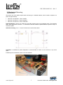
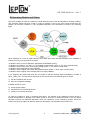
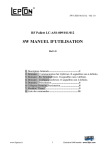
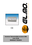
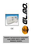
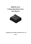
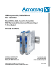
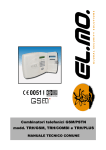
1
HW USER MANUAL – Rel 1.3
RF Pallet LC-ASS-009/011/012
HW USER MANUAL
Rel 1.3
1) General Description.................................................2
2) Mechanical Mounting..............................................3
3) Electrical Connections.............................................4
4) Interface Connector Description ..............................5
5) Leds ........................................................................7
6) Operating Models and States ..................................8
7) Alarms.....................................................................9
8) Factory Configuration ...........................................10
www.lepcon.it
1
Exclusive HAM market : www.i0jxx.com
HW USER MANUAL – Rel 1.3
1) General Description
This manual illustrates the uses of the modules
€
€
€
LC-ASS-009 - 1 kW 144 MHz
LC-ASS-011 - 500 W 432 MHz
LC-ASS-012 - 250 W 1290 MHz
which share the same physical layout and the same control and protection system, that is based on LepCon
module.
€
LC-ASS-010 - Dual Channel Bias Controller.
Bias Controller performs two macro functions:
€ It oversees the functioning of the amplifier in different operating methods, monitoring constantly the most
important working parameters and eventually implementing security strategies;
€ It allows the interview with an host in order to;
o configure, not in an ephemeral way, different operating methods
o real-time monitor the main working parameters and alarm conditions.
The initial configuration of the amplifier has been chosen so that the user can avoid using the serial
connection with PC.
www.lepcon.it
2
Exclusive HAM market : www.i0jxx.com
HW USER MANUAL – Rel 1.3
2) Mechanical Mounting
The proper use of the pallet requires itself monitoring on a suitable heatsink, which is able to dispose of a
power of approximately:
€
€
€
400 W for LC-ASS-009 - 1 kW 144 MHz
350 W for LC-ASS-011 - 500 W 432 MHz
250 W for LC-ASS-012 - 250 W 1290 MHz
Pallet preparation: remove any oxide from the pallet surface close to the heatsink using a fine abrasive
paste, then degrease the surface. To minimize the thermal resistance pallet-heatsink, lay down a layer of
conductive paste.
Heatsink mounting: use n° 7 screws TC M3x12 mm with its flat washer.
Ventilation: to facilitate the power dissipation is recommended to ensure an even air flow on top of the
pallet.
Indicatively here is attached a photo of the test heatsink.
www.lepcon.it
3
Exclusive HAM market : www.i0jxx.com
HW USER MANUAL – Rel 1.3
3) Electrical Connections
The amplifier requires some fundamental connections such as:
€
€
€
Power supply, +V and GND,
Input signal, RF_In,
Output signal, RF Out.
In addition for advanced features you need the connections that are available on the Interface Connector of
14 pin, whose description is shown in the table. Among the available features there are:
€
€
€
€
€
€
Input/output UART_RX/TX at level RS-232 for asynchronous serial connection
input TTL of enabling to transmission PTT (Push to talk)
input TTL of INHIBIT for amplifier’s On/Off and alarms reset
analog output of V_NTC temperature sensor
output TTL of ALARM to indicate the alarms
in/out I2C_SDA/SCL at TTL level for synchronous serial connection I2C o SPI
Bay way of an example:
www.lepcon.it
4
Exclusive HAM market : www.i0jxx.com
HW USER MANUAL – Rel 1.3
4) Interface Connector Description
UART_TX/RX: signal pair to RS-232 level, related to GND, that constitute
the asynchronous serial interface to a host (typically a PC). Trough the
cable with DB9-M connector, as shown in the diagram alongside, you can
connect directly to an interface DTE standard DB9-F. Connection
parameters are 9600-N-8-1.
INHIBIT: signal to TTL level with internal pull-up, that allows to switch off the
RF part of the amplifier, stopping the LDMOS alimentation. The signal is active
low, so:
€
€
when INHIBIT is in GND the amplifier is at rest,
when INHIBIT is at +5V or when it is left open the amplifier is powered.
This feature can be enabled or disabled through SW configuration; even if it’s
disabled the amplifier is powered. INHIBIT input has also a second feature which is independent by enabling:
the transition from GND to +5V entails the RESTART of the amplifier (see below) putting it out from the
alarm condition. In order to use this feature you can connect this input to a button (usually to GND).
PTT: signal of TTL level with internal pull-up that leds the amplifier to a low power state. It can be used in a
transmitter receiver system, in order to avoid that when it is in RX power isn’t dissipated at rest.
Consider that with bias stream of 2A and supply of 48V you will get a dissipated power of 1000W.
The signal is active low so:
€
€
when PTT is in GND the amplifier in on,
when PTT is at +5V, or when it is left open the amplifier is at rest..
This feature can be enabled or disabled through SW configuration; even if it’s disabled the amplifier is
powered.
Note: when inputs INHIBIT and PTT are activated at the same time INHIBIT function takes priority on PTT.
www.lepcon.it
5
Exclusive HAM market : www.i0jxx.com
HW USER MANUAL – Rel 1.3
V_NTC: analog signal, variable in the range 0-5V, linked to the
temperature of the amplifier module. It is obtained from a sensor
NTC PANASONIC ERTJ1VT222H type which has a resistancetemperature governed by the Steinhart–Hart curve of the first
order
R(T) = R(T0) exp (B*(1/T – 1/T0 ))
where:
T0
R(T0)
B
= 298.16K(25°C),
= 2200Ohm,
= 4450K.
The NTC is internally powered at 5V through a 3. 3 kOhm resistor and voltage is put out through an analog
buffer. From the voltage value, through an appropriate processing, it is possible to trace the value of
resistance R(T) of the NTC
R(T) = V_NTC*3300/(5-V_NTC)
And from this value it is possible to trace the temperature in Kelvin through the Steinhart-Hart inverse
function:
1/T = 1/T0 + 1/B * ln(R(T)/R(T0)).
With this sensor Bias Controller follows the compensation functions and thermal protection.
A possible use of this output may be to drive an analog comparator that enables a forced ventilation at a
certain temperature value.
ALARM: signal of TTL level that gets active when one of the possible alarm conditions is underway.
I2C_SDA/SCL: reserved for future use or upon request.
www.lepcon.it
6
Exclusive HAM market : www.i0jxx.com
HW USER MANUAL – Rel 1.3
5) Leds
The Bias Control module is provided with three leds in red, green and yellow, that with various ignition
systems and modulations indicate the various machine conditions. As a general rule the red, apart from the
case of Self Test, is used to indicate an alarm condition: in this case the other two leds code the alarm
cause. When Red led is off, yellow and green leds indicate the operating States of the machine. Some of the
states shown in the table are not of interest to the user.
The use of this table is fundamental to understand the status of the amplifier, especially when it is used
without the conjunction with the monitoring SW.
For the correct interpretation you should take into account that for each STATE, each row indicates a
"timeline" of 100mS and it has to be considered cyclically. For example, the TC state the table represents an
alternate blinking of both yellow and green leds.
www.lepcon.it
7
Exclusive HAM market : www.i0jxx.com
HW USER MANUAL – Rel 1.3
6) Operating Models and States
The entire amplifier is ruled by a machine of finite states that every 128 µS elaborates a working condition.
This evolution speed has been chosen in order to respond in time to the most critical events that can
happen, as the alarm conditions. A very simplified description of the automaton is shown in the following
figure.
When switched on it runs an initial self-test, which lasts about 20S and that evaluates if the hardware is
working correctly, running a series of checks:
• evaluation of the correct configuration parameters in EEPROM memory,
• evaluation of voltages 3. 3 V and 5. 0 V of the Bias Control module (within +/- 5% of the nominal value),
• evaluation of the correct value of the supply voltage (within +/- 5% of the nominal value),
• evaluation of the temperature sensor integrity,
• evaluation of the integrity of the active RF LDMOS element (within +/- 20% of the nominal value)
• evaluation of the integrity of the selecting switch to supply LDMOS.
If one sequence test fails further tests are not carried on and the machine stops immediately in a State of
SELF_TEST_FAIL. The fact that the self does not succeed is due to two different types of causes:
1) self test conditions are not met
2) there is a hardware breakage
Possible causes of 1) are:
a) wrong supply voltage
b) temperature out of operating bounds
c) presence of incoming RF signal
To clarify the reason for point c) remember that during the self-test of the LDMOS the active device in
thermal compensation is brought to the rated current of 1A and it is verified that each of the two active
elements involves the expected absorption within the tolerances of the measuring system. Since the
presence of input RF signal can alter the amount of absorption, it is impossible for the test to run.
www.lepcon.it
8
Exclusive HAM market : www.i0jxx.com
HW USER MANUAL – Rel 1.3
If the self test succeeds, rather everything works correctly, depending on the configuration, the machine can
run:
€
€
in TEMP_COMP where bias is steady at the reference value set in the configuration memory,
in WAIT_PTT where the active device is kept off. In this State there is no power absorption. From this
state, you can still move to the TEMP_COMP state by activating the PTT on the input interface
connector.
The TEMP_COMP is the operating state in which LDMOS works and it is thermally stabilized on a working
point, in order to allow the RF signal amplification .
7) Alarms
If when the amplifier is on:
a)
b)
c)
d)
it overheats or rather the temperature rises more than 80°C,
it is driven by an excessive input signal,
it absorbs an excessive stream,
it is supplied through an irregular voltage
it comes to the state ALARM. When it comes into this state:
1) in all cases the gate polarization is removed from LDMOS;
2) in cases a), c) e d) the LDMOS supply is removed too.
Note that the action 1) in case of b) makes the amplifier remain operating but with a considerable input
desensitization. This ensure that in case of excessive handling an automatic reduction of the overall signal,
AC+DC, on LDMOS gates will be realized. This protection intervenes within 1mS when the input signal
exceeds the warning threshold set in the Fw.
Note: protection for excessive handling allows you to implement a partial protection of the input of
LDMOS.
This protection, although partial, is beneficial to the transients of electrical mains absorption
which occur for instance in a use of CW type, when the input signal starts to work. This happens because
as the driving LDMOS driving starts it works always in a smooth way.
To reactivate the amplifier from the ALARM State it requires a RESTART.
€
If it was in alarm state because of excessive temperature, then returning to the same operating state or
not depends on the configuration. If in the configuration memory you have enabled automatic restart,
then it leaves the alarm when the temperature drops below 70° c. Alternately, if the auto restart is not
enabled, the manual restart is required (see below).
€
If it was in alarm state because of excessive monitoring, then returning to the same operating state, or
not, depends on the configuration. If in the configuration memory you have enabled automatic restart,
then it leaves the alarm when the input signal is reduced. Alternately, if the auto restart is not enabled,
the manual restart is required (see below).
If it was in alarm state because of excessive power consumption, or because of supply voltage
outside limits, equal to +5%\/ -10% of the nominal value, then the return to the same operating state is
possible only through manual restart (see below).
€
www.lepcon.it
9
Exclusive HAM market : www.i0jxx.com
HW USER MANUAL – Rel 1.3
Manual restart can be performed in one of the following three ways:
1. by switching off and on the amplifier
2. by performing a transition GND€+5V of the input Inhibit
3. by sending an appropriate serial control (see handbook SW)
8) Factory Configuration
See the list of the possible operating options that you can select through SW:
€
Enable Self Start: after the Self Test it makes the machine go into STOP or TEMP_COMP. If it is not
enabled the machine passes the self test and goes in STOP. From this state it can go in TEMP_COMP
only by the serial port control •btc‚.
It should be always on.
€
Enable Inhibit: it enables the hardware control Inhibit
€
Enable PTT: it enables the hardware control PTT (Push To Talk)
€
Enable Pw. In. Alr.: it enables the alarm for excessive monitoring
€
Self Res. Pw. In. Alr.: it indicates if after an alarm for excessive monitoring the machine is gone out
automatically (the input signal is reduced)
€
Self Res. Temp. Alr: it indicates if the machine is automatically out from an alarm due to the excessive
temperature when it decreases.
The factory amplifier configuration provides:
Enable Self Start
Enable Inhibit
Enable PTT:
Enable Pw. In. Alr.
Self Res. Pw. In. Alr.
Self Res. Temp. Alr:
€
€
€
€
€
€
on
on
on
on
on
on
For a preliminary test of the amplifier it is required:
€
€
PTT connected to GND,
INHIBIT left open.
Warranty: the warranty is valid for one year from date of purchase. This warranty does NOT cover any
breakage of the Mosfet. This warranty does NOT cover any improper use of the module and the nonobservance of the instructions above. Shipping costs are charged to the customer.
www.lepcon.it
10
Exclusive HAM market : www.i0jxx.com