1
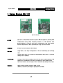
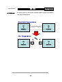
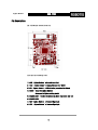
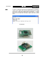
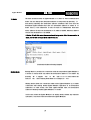
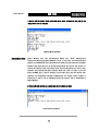
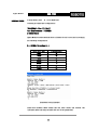
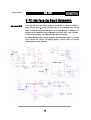
User’s Manual 2006-07-06
Closer to Real,
Zigbee Module
ZIG-100
Wireless Communication
ROBOTIS CO.,LTD. www.robotis.com ☏ +82-2-2168-8787
Zigbee Module
ZIG-100
Contents
1. Zigbee Module ZIG-100
Page 02
2. Zigbee Setting
Page 06
3. PC Interface Zig Board Schematic
Page 10
1
ZIG-100
Zigbee Module
1. Zigbee Module ZIG-100
[ZIG-100 Circuit]
ZIG-100
ZIG-100 is a small module that has a built-in MCU and Zigbee IC, allowing UART
communication using 2.4GHz frequency. Utilized as a PAN (Personal Area
Network) Module, it replaces wired serial communication with more modern
wireless characteristics. Basic specifications of Zig-100 are as follows.
Bandwidth
RF Data Transfer Bandwidth : MAX 250kbps
Interface
Using UART, it can setup configuration as well as transmitting and receiving
data.
Various Baud Rates are supported. Recommended Baud Rate is between
9600bps and 115200bps.
Power Supply
Voltage of 2.7V~3.6V is normally used in ZIG-100, and for stable operation, 3.3V
Regulator is recommended. The power consumption is about 30mAh in 3.3V.
Take note, however, that the usage of more than 3.6V may damage the product.
Dimension
Width X Length X Height: 26.5mm x 19mm x 12mm
(Without a connector, the height is getting lower as 6mm.)
2
ZIG-100
Zigbee Module
ZIG-100 Concept
As shown below, Zig-100 provides innovative wireless solution that replaces
wired serial communication.
Wired Serial Communication
PC
TxD
TxD
PC
or
RxD
RxD
or
Embedded
GND
GND
Embedded
TxD
PC
After Zigbee applied
PC
TxD
Zigbee
Zigbee
or
RxD
RxD
or
Embedded
GND
GND
Embedded
3.3V
3
3.3V
ZIG-100
Zigbee Module
Pin Description
ZIG-100 Module viewed from top.
Each pin has following roles.
1 : GND - Zigbee Module’s Ground Level (0v)
2 : VCC - Zigbee Module’s Supply Voltage ( 2.7~3.6V )
3 : LED - Zigbee Module’s LED indicating a connection status
4 : /RESET – Reset for Zigbee Module
(Also used in Zigbee setting mode)
5 : CHANNEL_SEL1 - Used in Broadcasting Mode (Explained later on)
6 : CHANNEL_SEL2
7 : TXD - Zigbee Module’s Transmit Signal pin
8 : RXD - Zigbee Module’s Receive Signal pin
4
ZIG-100
Zigbee Module
Setting
To check or to change the setup status of the Zigbee Module, it is necessary to
connect to PC as shown in page 3. Run the terminal program and set to 57600
bps, No Parity, 1 Stop Bit. Next, supplying power and transmitting “!”to Zigbee
Module after reset within 60ms will change to Zigbee setup mode as shown
below.
(In setup mode)
5
ZIG-100
Zigbee Module
2. Zigbee Setting
ZIG-100 Operation Mode
Basically, Zigbee Module has a 16 bit address and each Zigbee Module has its
own unique address. It can have any address between 1 and 65535; however,
Address 65535 (0xFFFF) is reserved for broadcasting mode.
Zigbee Module ZIG-100 has three operation modes. Each mode can be directly
controlled through terminal while it is in setup mode. Refer to page 5 to go into
the setup mode.
Take Notes
Keep in mind of following matters in setup mode.
1.
Take note that only hexadecimal is used in Zigbee setup mode
2.
Zigbee setup mode is always operated in 57600bps.
3.
If you don’t know the Baud rate of Zigbee Module, go to 57600bps setup
mode and change the Baud Rate as required.
4.
In Pin Description, when you connect Status LED pin to LED, you can check
the connection status with blinking of LED.
6
Zigbee Module
1:1 Mode
ZIG-100
The basic operation mode of Zigbee Module is 1:1 (Peer-to-Peer) communication
mode. You can change the destination address in setup mode by pressing “D”
and directly inputting the destination address afterward. Take note that the
destination zigbee module must also set destination address of sender in 1:1
mode. That is, if the addresses 10 and 15 wants to communicate with each
other, address 10 must set destination to 15, which is 0x000F, whereas, address
15 must set destination to 10, 0x000A.
A Status LED will blink when the connection is being made. After the connection is
made, the LED will no longer blink and will stay on.
(Destination Address Setting Example)
Waiting Mode
Waiting Mode is provided for connection with the unspecified Zigbee Module. It
is shown in setup mode only when the destination address is not 0xFFFF. By
pressing “W” it toggles “Yes” or “No” and it is in 1:1 mode when the
status is “No,” and in waiting mode when it is changed to “Yes.”
Waiting mode allows the connection when other Zigbee Modules try to make
connection with waiting moded Zigbee Module regardless of its destination
addresses. In other words, the other Zigbee Module must set destination
address of waiting-moded Zigbee Module in 1:1 mode.
In this case, when the Zigbee Module is in waiting mode, without any separate
operation, it can form connection with other Zigbee Modules.
7
ZIG-100
Zigbee Module
A Status LED will slowly blink in Waiting Mode. After connection, the LED will no
longer blink and will stay on.
(Waiting Mode Example)
BroadCasting Mode
Zigbee
Module
also
has
Broadcasting
Mode
that
allows
simultaneous
connections with many Zigbee Modules. To do so, you must set the destination
address to 65535(0xFFFF) first. Upon doing so, when you send a packet, all Zigbee
modules that have been set as Broadcasting Mode will receive the packet. To
control the chaotic traffic that might result from broadcasting, you can set four
channels only through hardware setting. When you refer to page 4, you will
notice CHANNEL_SEL1, 2 pins in number 5 and 6 pins. Here, you can choose four
channels by configuring low/high combinations. On default when nothing is
connected, it will be set to high/high by Pull-up Resistor that is embedded in
Zigbee Module.
A Status LED light will be on continuously in BroadCasting Mode.
(In Broadcasting Mode)
8
ZIG-100
Zigbee Module
Baud Rate Setting
In setup mode, press “B” to set Baud Rate.
Following are Baud Rate configurations.
Target Baud = ( fosc / 8 ) / (x + 1 )
fosc : Main Frequency - 7.3728MHz
x : divider factor
Zigbee Module involves method where x (Divider Factor) is used and accordingly,
use following configurations.
X = ( 921600 / Target Baud ) – 1
Target Baud (bps)
X (Hexadecimal)
9600
5F
14400
3F
19200
2F
28800
1F
38400
17
57600
0F
115200
07
(Baud Rate Example)
(Baud Rate Setting Example.)
Baud Rate between 9600~115200 bps has been tested and verified. The
operation above this range of baud rate can not be guaranteed.
9
Zigbee Module
ZIG-100
3. PC Interface Zig Board Schematic
Interface with PC
To use Zig-100 in PC, you need a simple Zig board. That is, COM Port or USB-toSerial module sends ±12V RS-232 signal and to be compatible with ZIG-100
(3.3V), it needs RS-232 Drivers/Receivers IC of either MAX232 or MAX3232. For
example, below schematics illustrate MAX232, and in VCC, only 4~5.5V is allowed.
In case of using regular 1.5V alkaline battery, three are needed.
For Zigbee Module power, Voltage Regulator and additionally, LM1117-3.3V was
used. Through the various LED blinking pattern, current status of ZIG-100
communication can be checked.
10