1
THE PENNSYLVANIA STATE UNIVERSITY
SCHREYER HONORS COLLEGE
DEPARTMENT OF MECHANICAL AND NUCLEAR ENGINEERING
DESIGN AND PROTOTYPING OF A ROBOTIC RESEARCH VEHICLE TO
INVESTIGATE AND VERIFY THE CALCULATED EFFECT OF COMBINED
LOCOMOTION AND SERPENTINE GAIT
TREVOR J. OWEN
Spring 2009
A thesis
submitted in partial fulfillment
of the requirements
for a baccalaureate degree
in Mechanical Engineering
with honors in Mechanical Engineering
Reviewed and approved* by the following:
Sean N. Brennan
Assistant Professor of Mechanical Engineering
Thesis Supervisor
Matthew M. Mench
Associate Professor of Mechanical Engineering
Director, Fuel Cell Dynamics and Diagnostics Laboratory
Honors Adviser
* Signatures are on file in the Schreyer Honors College
We approve the thesis of Trevor J. Owen:
Date of Signature
_____________________________________
____________
Sean N. Brennan
Assistant Professor of Mechanical Engineering
Thesis Supervisor
_____________________________________
____________
Matthew M. Mench
Associate Professor of Mechanical Engineering
Director, Fuel Cell Dynamics and Diagnostics Laboratory
Honors Adviser
9-1311-7522
Abstract
Throughout the last 20 years, a lot of work has been done on the investigation into
serpentine dynamics and developing mathematical models for motion. However, there
has not been as much work testing the dynamic models with hardware. The purpose of
this thesis is to design and prototype a research vehicle to test various models of
serpentine dynamics which include serpentine gait and powered wheel locomotion.
In designing the robot, selecting the proper hardware was the foundation on which
to build on. For the links, the AX-12 servo was chosen for its networkability to power
both the link angle and wheels. To control the entire robot, the CM-5 controller module
was superior to other options because of its programming library, serial hardware switch,
extended memory, and superior power source. These components combined with a
framing kit comprised the structure of the robot.
In accordance with the mathematical model, the robot was designed with 6 links
and 5 joints. The programming was structured with a user interface to walk the user
through the experiment including preset variables or user defined variables. During the
experiments, the robot would not be tethered for the duration and then reconnected at the
end for data collection. There are many different modes of motion and feedback
parameters included in the robot which make it very reconfigurable.
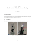
The robot was tested for operation and showed very promising serpentine motion
and feedback operation. It holds a number of advantages over the previous versions as
well as huge potential for further experiments. This robot allows for many different types
of testing utilizing a serpentine gait and configurable powered wheels.
Table of Contents
Introduction .....................................................................Page 1
Robot Hardware Selection ...........................................Page 2
The AX-12 Networkable Servo ...............................Page 2
The CM-5 Control Module ......................................Page 4
Robot Body Design........................................................Page 8
Link Design ..............................................................Page 8
Wheel Design ...........................................................Page 9
Robot Program and User Interface .......................... Page 11
Testing the Robot Program and Hardware ............ Page 14
Train Test .............................................................. Page 14
Serpentine Test ...................................................... Page 15
Conclusions .................................................................. Page 17
Recommendations ....................................................... Page 17
Works Cited .................................................................. Page 18
Appendix ....................................................................... Page 19
Introduction
The study of snake dynamics is a relatively new field. Snake motion is fairly
complex and is generally viewed as being an inefficient mode of travel. In the last 20
years, work has been done to calculate mathematical models and dynamics of snake
motion and it is a common practice to model a snake’s motion as a segmented body with
a single axle and two wheels on each segment. However, these theories are seldom tested
with actual hardware. The purpose of this investigation is to create a research vehicle
which can be used to test combinations of snake dynamics that include serpentine gait as
well as powered wheel locomotion.
This project intends to build on the success of an earlier project by Vipul Mehta
(Mehta, Brennan, & Gandhi, 2008), which created a serpentine robot with free spinning
wheels. However, there were several setbacks with this project that needed to be
redesigned. The robot operated while attached to a tether which it relied on for control
and power. This made it difficult to operate and inconvenient in many situations.
Additionally, the general design, although operable, was cumbersome and fragile. The
joint between links was long and prone to bending. The wheels were too big and heavy.
The components of the links were bulky and needed a multitude of wires strung between
the joints. The redesign of the robot targets most of these areas and adds the ability to
power the robot’s wheels.
Page | 1
Robot Hardware Selection
The AX-12 Networkable Servo
The design for the robot depends on the foundation of properly selected servos.
Each link of the robot needed to have a servo to control the link angle, two servos to
power the wheels, feedback hardware such as encoders and current meters, as well as the
ability to power and command the servos. The previous version was made with all these
components separately and with the servos controlled individually through pulse width
modulation. Each link had a wire tether which made for awkward operation. For the
current version, new technology is available which simplifies all these operations.
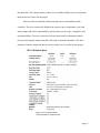
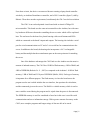
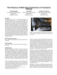
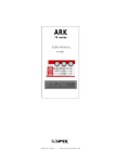
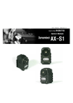
The servos chosen for this version of the robot were
AX-12s which are sold by Robotis under their Bioloid
product line (figure 1, figure 2). The design of the AX-12s
is special because each one houses a large amount of
technology that incorporates all the projects goals into a
compact package. The servos each contain an ATMega8
microcontroller (Hylands, 2008) which allows it to operate
Figure 1: AX-12+ (Trossen
Robotics, Dynamixel AX12+ Robot Actuator, 2009)
independently from the master controller. The servo casing also contains feedback
hardware and can report information and make decisions based on internal conditions.
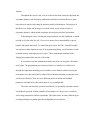
The servos have high torque for a relatively low weight (16.5 kgf-cm, 55g) (Robotis Co.
L. , Bioloid User's Guide, 2007). In addition, each servo is modular and has several
attachment points which can be used for snake construction, making the servo itself into
Page | 2
the snake link. The compact nature of these servos and their ability to do so much made
them an obvious choice for the project.
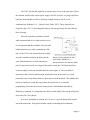
Each servo has a multitude of functions that can be commanded from the
controller. The servo can provide feedback on position, speed, temperature, load, and
input voltage and can be commanded by goal position, speed, torque, compliance, and
operational limits. The servo can make decisions based on this information without
having to interrupt the master controller, allowing for smoother operation. The sheer
amount of features compacted into the servos casing was very useful for this project.
Figure 2: AX-12 Specifications
(Trossen Robotics, Dynamixel AX12+ Robot Actuator, 2009)
Page | 3
The final feature that made this servo the best choice for the project was the ability to
daisy-chain as many as needed together with only a single power source and master
controller. The servos are connected to each other by a 3 wire cable containing power,
ground and data. The data is transmitted via half duplex asynchronous serial
communication which is transmitted to and from the servos. Each data packet contains a
servo identification number as well as instructions which allows the control of all the
servos connected on the same wire. What this meant for the project is that there only had
to be one controller and power source located at the head of the robot and would free up a
lot of wires required to run each servo individually. The ability to control all the servos
from a single local controller and power source gave the robot a huge advantage over the
previous model.
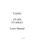
The CM-5 Control Module
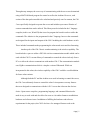
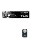
Now that the servo choice has been made, A
proper controller had to be chosen operate the robot.
The controller needed to fulfill certain requirements
including running a user interface, calculating the
positions of the servos, serially commanding the
Figure 3: CM-5 Module. (Trossen
Robotics, Bioloid CM-5 Control servos, and reading information from the servos. It
Module, 2009)
also needed sufficient speed to compute all the operations in order to maintain smooth
serpentine motion. Additionally, it needed to be small enough to be integrated into the
robot or have a wireless capability. Other qualities of the controller that were not required
but beneficial were ease of programming, open source code, low cost, and availability.
Page | 4
From these criteria, the choice was narrowed down to running a laptop based controller
wirelessly, an Arduino Duemilanove controller, and a CM-5 controller (figure 3) sold by
Robotis. These three met the requirements, but ultimately the CM-5 was the best solution.
The CM-5 is an enclosed printed circuit board with an Atmel ATMega128
microcontroller. This board uses the same microcontroller as the Arduino, but with some
key hardware differences that make controlling the servos easier which will be explained
later. The enclosure for the board is a plastic housing with several buttons and LEDs
which are connected to the board’s inputs and outputs. The housing also includes a serial
port for wired communication to a PC and a 3 wire serial bus for communication to the
servos. In addition to the board, the housing also incorporates a 9.6 V rechargeable
battery and has multiple hardware attachment spots on the outer perimeter for attaching
the servos.
One of the hardware advantages the CM-5 had over the Arduino was the massive
amount of onboard memory. The CM-5 has 128 KB of flash memory, 4 KB of RAM, and
4 KB of EEPROM (Robotis Co. L. , 2007) as compared to the Arduino’s 16 KB of flash
memory, 1 KB of RAM and 512 bytes of EEPROM (Mellis, 2009). Each type of memory
is important for a different purpose. The flash memory is where the board stores the
program used to run it which includes the user interface, the equations for calculation,
and the commands given to the servos. The RAM is a volatile memory which is used to
store variables created during the program and is wiped when the power is disconnected.
The EEPROM memory is used for a multitude of uses but in this case is used for serial
communication and servo information storage. With a greater amount of memory on the
CM-5, more complex programs and longer strings of data are able to be stored.
Page | 5
The CM-5 also has the capability to operate many servos at the same time. Where
the Arduino would need a custom power supply, the CM-5 has two very large capacitors
built into the board that are able to discharge enough current to run 28 servos
simultaneously (Robotis Co. L. , Bioloid User's Guide, 2007). These capacitors are
charged by the 9.6V 2.3 Ah rechargeable battery with enough charge for more than an
hour of testing.
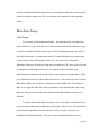
Since the controller would have to both
send commands and receive data from the servos,
it was important that the controller selected could
both send and receive serial commands at a fast
rate. As the AX-12 unit operates both on a single
wire, the controller needed to be able to do the
same. Both boards have a serial transmission
Figure 4: Circuit diagram for CM-5
serial switch. (Robotis Co. L. ,
Dynamixel AX-12 User Manual, 2006)
port (Tx port) and a serial receiving port (Rx port) but only the CM-5 had a hardware
switch to rapidly switch one on and disable the other (figure 4). The reason this is
important is that a serial communication in both directions on the same wire could
potentially cause a loop between the two ports and overload the board. The Arduino does
not have a hardware switch, but can perform the switch slower via software
programming. Since the servos send a return packet of information immediately
following a command, it is important to be able to switch rapidly between the serial ports
and so the CM-5 was chosen.
In order to communicate with the AX-12 servos, a specific data packet must be
sent with instructions. This packet includes complex formatting and calculations.
Page | 6
Through many attempts, the exact way of communicating with the servos was determined
using a MATLAB based program for control as well as the Arduino. However, each
section of the data packet needed to be calculated and precisely sent. In contrast, the CM5 was specifically designed to operate the servos and includes open source libraries of
custom commands that can be utilized. This library must be included in the C language
compiler (in this case, WinAVR) that is used to program the board in order to utilize the
commands. The Arduino is also programmed in the C language, however the commands
are designed for the inputs and outputs of the CM-5 including the serial hardware switch.
These included commands make programming the robot much easier and less frustrating.
Another perk of the CM-5 that is worth mentioning is the wireless capability. The
board includes a space to solder a ZIG-100 wireless communication module which can be
used with the CM-5’s custom library of commands to control the robot wirelessly from a
PC or to allow the robot to communicate with another CM-5. The communication module
uses ZigBee communication which is a simpler version of Bluetooth. While not
incorporated in this robot, the wireless capability of the CM-5 could be a useful addition
for future robot variants.
Although both the PC and the Arduino were used in learning to control the servos,
the CM-5 was ultimately chosen to control the robot. It incorporates so many features
that were designed to communicate with the AX-12 servos that it became the obvious
choice. Open source compilers, programming language, and command libraries also
make it easy to work with and also allow for users to visit online forums to troubleshoot
hardware and software issues. In addition to fulfilling the hardware and software
requirements for the project, the CM-5 also has a few untapped features such as the
Page | 7
wireless communication feature that make it a promising board for future versions of the
robot. For all these reasons, the CM-5 was chosen as the controller for the serpentine
robot.
Robot Body Design
Link Design
To accurately fit the mathematical model, the serpentine robot was designed to
have 6 links and 5 joints. This allowed for a direct match to the model without having to
consider extra links. Each link is made up of 2 AX-12s driving the wheels and 1 AX-12
driving the link angle. A considerable amount of framing holds the servos together and
connects them to the following link. Lastly, each servo is wired in a daisy-chain
formation to the next. At the head of the robot is attached the CM-5 unit, which will send
commands down the length of the robot. This caused a problem with the weight
distribution as the mathematical model calls for equal weight on each link and the CM-5
is a significant amount of weight to add to the first servo. This caused the robot to arch in
the middle slightly, decreasing the frictional force on the middle links. The solution to
this was to weight the other links with scrap metal to evenly distribute the weight along
the robot. The robots form matches the mathematical model in shape and degrees of
freedom.
To further separate the robot from the previous version, this version had servos to
power the wheels and explore a different set of dynamics. However, the robot also had to
be backwards compatible to test free wheels as well. As a result, each wheel was
designed for four different modes. The wheels can be attached firmly to the servos,
Page | 8
allowing for no slip to test high torque applications, or be attached on bushings which
allow for backwards compatible free wheel motion. Also, the wheels were given a set of
ratchets. This allowed for powered or unpowered wheels that could only move in one
direction. The new transformable wheels allow for many different modes of testing,
increasing the possibilities of research for the robot.
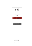
Wheel Design
The design of the wheels to allow for so many
different modes was complicated. Each servo spins a flat
disc which has 4 attachment points on it (figure 5). For
firmly attached wheels, the wheels were simply screwed in
at these 4 points. However, for the other three modes of
motion it became more difficult. Ratchets had to be
designed that could handle free spinning wheels as well as
ratchet wheels. Many different designs were attempted, but
Figure 5: AX-12 hub.
(Trossen Robotics,
Dynamixel AX-12+ Robot
Actuator, 2009)
the final design proved to easily accommodate all the modes of motion.
Ratchets are basically gears with directional teeth and are usually used for high
stress or long life applications. Unfortunately, this means
they are usually made out of metal and very expensive to
make. For the ratchets on the robot, a cheaper solution had
to be found. Nylon gears are relatively inexpensive and are
easily machined to fit a custom purpose and so they were
used as the basis of the ratchet (figure 6). The outward
Figure 6: Wheel ratchet
Page | 9
pointing gear teeth are not ideal, but for this application they are sufficient. To prepare
each gear for mounting, they needed to have the hub machined off and 4 holes drilled to
match the mounting on the servo. Once this was accomplished, a plastic bushing was
bonded coaxially to the outer surface of the gear to provide a frictionless mount for the
wheel. In addition to the gear, every ratchet needs a pawl which stops the gear from
rotating backwards. This part is usually a solid piece held down by a spring. For this
robot, a springy piece of plastic anchored on the wheel itself was used. The plastic is held
at a near tangential angle to the gear so that it locks when trying to move the wrong
direction. This completes the ratchet and covers the two ratcheted modes of motion. In
addition to this, extra wheels are on hand to replace those with a pawl attached in order to
have free spinning wheels. Each type of wheel is held on the bushing with a washer and
nut on the outside.
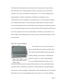
The robot is complete physically (figure 7). It has the exact form to match the
mathematical model and is reconfigurable to test different modes of motion. The
microcontroller and power source allow the robot to run independently and tether-free for
operational convenience. The next step in finishing the design of this robot is to complete
the software side and program the robot to accept multiple profiles of motion.
Figure 7: Completed serpentine robot
Page | 10
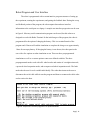
Robot Program and User Interface
The robot is programmed with a certain intuitive program structure of setting up
the experiment, running the experiments, and getting the feedback data. During the set up
and feedback portion of the program, the robot outputs data and user interface
information to the serial port on a laptop. A sample user interface progression can be seen
in figure 8. Most any serial communication program can be used, but this robot was
designed to work with Robot Terminal. In the initial stages of the program, the robot is
programmed for the option of charging the battery. This is a terminal branch of the
program and if chosen will end the simulation to complete the charge over approximately
1 hour for an empty battery. If charging the battery is not chosen, the robot queries the
user with a few options on what simulation to run. There are three preprogrammed
simulations as well as a custom option to enter user defined variables. The three
preprogrammed modes work with all 4 wheel modes and consist of a straight train mode,
a powered wheel serpentine mode, and an unpowered wheel serpentine mode. The forth
mode asks the user for each variable individually. The robot then instructs the user to
disconnect the serial cable while it runs the program and then to reconnect the cable at the
end to retrieve the data.
Figure 8: Sample user interface progression for powered wheels.
Page | 11
The control formula for the motion of the serpentine robot is based on the work of
Vipul Mehta in his paper on serpentine gait (Mehta, Brennan, & Gandhi, 2008). It is
sinusoidal in describing the motion of the first link and adds a phase lag for each
additional link (figure 9). The code written for
the serpentine robot uses this sinusoidal
equation to calculate the goal position of each
Figure 9: Equation of snake motion
(Mehta, Brennan, & Gandhi, 2008)
link to create a sinusoid profile and continuously sends an updated profile until a
designated end time. This creates the sinusoidal motion needed to propel the robot
forward. The sinusoidal motion is characterized by 4 variables: amplitude, frequency,
time step, and phase lag. As the time step and frequency both have an equal effect on the
sinusoid, the time step is fixed and the frequency is used to change the profile. There are
two things that make this motion of the robot counterintuitive. First is that if the links are
calculated from the first link back to the tail, the time variable must be set as a negative
value. This allows the sinusoidal motion to move down the tail rather than up it. Also, the
amplitude and frequency variables only control the sinusoidal motion of the first link, not
the entire profile. The subsequent links are controlled by the phase lag variable, which
can be set low for a tighter sinusoid or high for a loose sinusoid. The code structure is
seen in figure 10. The centerline for the position of the servo is 512 of the total range of
1023. This means the sinusoidal wave needs to be converted to the specified range.
Page | 12
for (t = 1; t <= trun;)
{
for (bID = 1; bID <= 5; bID++)
{
pos = (a*sin(w*-t+(bID-1)*b)*200)+512;
WriteWord(bID, P_GOAL_POSITION_L , pos);
}
t += tstep;
MiliSec(50);
}
Figure 10: Code segment for calculating and
commanding servo position.
In addition to the commands sent down the servo chain, the CM-5 also reads any
feedback parameter of the AX-12. The speed of communication is so high (1 MB/sec)
that it does not affect the fluidity of motion. This includes the load, position, voltage, or
speed of the servo. The variable measured depends on the parameter being tested. The
CM-5 starts to read feedback information towards the end of the run (for steady state
conditions) and stores the information in an array that is later uploaded to a PC. This
stored data is located in the volatile part of the robot’s memory and is lost once the power
is shut off. Once the user has reconnected and downloaded the stored feedback data, the
experiment is concluded and the program reaches its end.
Page | 13
Testing the Robot Program and Hardware
In order to verify the operation of the robot and its feedback data, it was tested
under several different modes. These modes were used to verify the robot’s ability to
gather data as well as test its physical abilities. The first mode tested was a straight train
mode to test wheel operation, wheel feedback, and joint hold. In addition to a flat surface,
the train mode was tested on an inclined ramp to test for ratchet holding strength. After
the incline, the snake was tested in its sinusoidal mode with both powered wheels and
unpowered wheels to test for joint feedback and snake motion similar to the previously
created robot. Through these tests, the robot was tested to ensure proper operation and its
capability to test experimental snake dynamics.
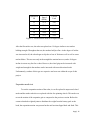
Train mode test
Putting the robot into a straight train mode is as easy as setting the amplitude
variable equal to zero and running the powered wheel simulation. Once the test was
underway, the robot performed as expected. All 12 wheels were turning at the assigned
speed and the joints were holding in a straight line. Upon completion of the test, the robot
was reconnected and the feedback data proved that the controller had successfully
retrieved and stored wheel load and speed. A small portion of the feedback data can be
seen in figure 11.
Page | 14
11
Current
Speed
(RPM)
51.4
12
52.6
1103
13
55.4
992
14
50.8
1135
Dynamixel
ID
Current
Load
920
15
51.8
928
Figure 11: Feedback data from the straight train test.
After the flat surface test, the robot was placed on a 30 degree incline to test ratchet
holding strength. Throughout the test, the ratchets held just fine. As the degree of incline
was increased to 40, the robot began to slip due to loss of friction as well as well as some
ratchet failure. This test was only in the straight line motion however, and a 40 degree
incline is not an easy feat for a robot. However, the wheel grip can be increased with
weight and strength in the ratchets can be increased with more directional teeth.
Unfortunately, ratchets of this type are expensive and were not within the scope of this
project.
Serpentine mode test
To test the serpentine motion of the robot, it was first placed in unpowered wheel
mode and the ratchet wheels were replaced with the free spinning wheels. This mode was
to test the motion of the serpentine gait as compared to the previous version. Before the
current robot had weighted joints to distribute the weight from the battery pack at the
head, the serpentine motion was present but the mid section slipped back and forth. This
Page | 15
meant that the mid section was not contributing to the forward motion and the front and
back sections were doing all the work. However, after weights were added to equalize the
load, the robot worked very well and equaled if not outperformed the previous version of
the robot.
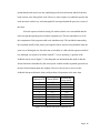
After the unpowered wheel testing, the ratchet wheels were reassembled and the
robot was put through the powered wheel serpentine test. This test intended to see if all
the components of the program could work simultaneously. This included commanding
the serpentine profile of the joints, powering the wheels, and receiving feedback from the
joint servos. During the test, the robot ran as smoothly as it did with the unpowered wheel
test, although it was quite a bit louder with all 17 servos operating. A portion of the
feedback can be seen in figure 12. One thing that was noted about this mode is that the
forward motion is dominated by the wheel speed variable and the serpentine gait seems to
increase forward momentum only slightly. However, the test was a success as the
feedback data proved that the robot could perform all operations at the same time.
Position (deg
from center)
1
11.6
29.6
2
9.8
15.2
3
10.3
-2.05
4
3.6
-19.4
5
-11.7
-30.5
1
8.5
29.9
2
9.8
21.1
3
9.8
2.6
4
9.36
-14.4
5
-11.7
-31.1
Figure 12: Feedback data from serpentine test.
Dynamixel ID
Speed (RPM)
Page | 16
Conclusions
The final design for the robot turned out to be better than expected. The speed of
communication from the controller to the servos is so fast that the serpentine motion of
the robot is fluid despite the additional strain of data acquisition. In addition to the link
hardware, the ratcheting wheels turned out very well. With the rolling friction minimized
while still being able to prevent opposing motion, the ratchets perform their job well.
Also, the ability to operate the robot without a tether makes operation of the snake very
convenient and the user interface drastically lowers the learning curve. This robot fulfils
all the requirements needed to test experimental motion as defined by the mathematical
model.
Suggestions for Future Work
For future versions of this project, several changes could be made that could
improve the performance and capability of the robot. First, the ratchets worked well for
the materials that were available, but could be made better. However, the professionally
made metal ratchets are still too expensive. In the future, the ratchets should be drawn up
on a CAD program and cut out with a water jet or other rapid prototyping machine.
Properly angled teeth on a ratchet would cut down on rolling resistance as well as
increase the holding strength. Making this change would greatly increase the ratchet’s
performance. As for additional capabilities of the robot, the wireless capability of the
CM-5 should be utilized. Not only would the CM-5 be able to broadcast data during the
experiment, but the robot would not need to be attached during any part of the program.
Page | 17
Additionally, when the CM-5 is using the wireless module, it would allow for external
control by using a wireless controller. This, along with changes to the dynamic formula,
would allow the user to steer the robot for additional applications.
Page | 18
Works Cited
Hylands, J. (2008, June 27). AX-12 Page. Retrieved April 15, 2009, from TikiWiki:
http://www.bioloid.info/tiki/tiki-index.php?page=AX-12+page
Mehta, V., Brennan, S., & Gandhi, F. (2008). Experimentally Verified Optimal Serpentine Gait and
Hyperredundancy of a Rigid-Link Snake Robot. IEEE Transactions On Robotics , Vol. 24, No.2.
Mellis, D. A. (2009, March 24). Arduino Duemilanove. Retrieved April 15, 2009, from Arduino:
http://arduino.cc/en/Main/ArduinoBoardDuemilanove
Robotis Co., L. (2007). Bioloid Expert Manual. Bucheon-city, Gyeonggi-do, Republic of Korea:
Robotis Co., LTD.
Robotis Co., L. (2007). Bioloid User's Guide. Bucheon-city, Gyeonggi-do, Republic of Korea:
Robotis Co., LTD.
Robotis Co., L. (2006, 06 14). Dynamixel AX-12 User Manual. Burcheon-city, Gyeonggi-do,
Republic of Korea: Robotis Corporation.
Trossen Robotics, L. (2009). Bioloid CM-5 Control Module. Retrieved April 15, 2009, from Trossen
Robotics: http://www.trossenrobotics.com/bioloid-cm-5-control-module.aspx
Trossen Robotics, L. (2009). Dynamixel AX-12+ Robot Actuator. Retrieved April 15, 2009, from
Trossen Robotics: http://www.trossenrobotics.com/dynamixel-ax-12-robot-actuator.aspx
Page | 19
Appendix 1 – materials, tools, and programs used
Materials Used:
Part name
CM-5 Control Module
AX-12+ Robot Actuator
17 Servo Cables
BPF-F13/F14 Wheel and Tire Set
BPF-WA/BU Washer and Bushing set
BPF-F2 Frame
BPF-F10 Frame
BPF-F3 Frame
M3-10 Bolt
M3 Nut
M2-6 Bolt
M2 Nut
M2-10 Bolt
M3 Washer 15mm OD
Number
required
1
17
17
24
17
5
11
31
17
12
160
140
48
12
Tools Used:
Phillips screwdriver
Cutting tool
Milling Machine
Cordless Drill
Plastic Bonder
Threadlocker
Professional Epoxy
Programs Used:
Bioloid libraries and Terminal – Downloadable from www.robotis.com/zbxe/software_en
WinAVR – Downloadable from http://winavr.sourceforge.net/download.html
Page | 20
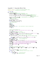
Appendix 2 – Serpentine Robot Code
#include " libCM-5.h" // allows use of Bioloid Command Library
#include "math.h" // allows use of trig functions
int main(void)
{
//initialize hardware
PortInitialize(); //initializes Serial ports
TimerInitialize(TIMER0, 128, 1); //Interrupt Enable
SerialInitialize(SERIAL_PORT0,1,RX_INTERRUPT); //485 serial communication to
Dynamixel Servos
SerialInitialize(SERIAL_PORT1,DEFAULT_BAUD_RATE,RX_INTERRUPT); //232 serial
communication to PC
ChargeInInterruptInitialize(); // initialize ability to charge battery
sei(); // initialize interrupt
//defining variables
int arraytotal, arraypos;
byte bID, bkey;
word pos, jspeed, wspeed, cwspeed;
float a, w, b, t, trun, tstep;
//User defined values
a = 0.8;
w = 0.5;
b = 0.8;
jspeed = 100;
wspeed = 400;
cwspeed = wspeed +1024;
trun = 30;
tstep = 0.5;
// must add 1024 for counter clockwise spin
//user interface message to PC
TxDString("\r\n Welcome to the Snake Robot Control Program \r\n");
MiliSec(1000); //pause for 1 second
LEDOn ( BIT_LED_MANA ); //turn on manage LED
TxDString("\r\n Would you like to charge the battery? (Up = yes/Down = no) \r\n");
bkey = WaitButtonChange(); //wait for user to make button choice
if (bkey == BIT_SW_UP) //if user selects to charge the battery
{
gbBatteryChargeMode = BATTERY_CHARGE_MODE_ING; //starts the battery charge
TxDString("\r\n Battery Charging... Restart program when finished.");
while(1){} //infinite loop to charge the battery
}
LEDOff (BIT_LED_MANA );
//turn off manage LED
MiliSec(1000);
LEDOn (BIT_LED_PROG); //turn on program LED
TxDString("\r\n Select one of the following options (Press directional button):
\r\n");
TxDString("\r\n
UP: Run winding serpentine program with powered wheels");
TxDString("\r\n DOWN: Run winding serpentine program with unpowered wheels");
TxDString("\r\n LEFT: Run straight train program presets");
TxDString("\r\n RIGHT: Use user defined values\r\n");
TxDString("\r\n Choice: ");
bkey = 0;
//while loop for incorrect button presses
while (bkey != BIT_SW_UP && bkey != BIT_SW_DN && bkey != BIT_SW_RT && bkey !=
BIT_SW_LF)
{
bkey = WaitButtonChange();
//wait for user choice
switch ( bkey )
//switch to determine actions from user's choice
{
case BIT_SW_UP:
TxDString("UP"); // clarifying choice
a = 0.8;
//redefining values
Page | 21
w = 0.5;
b = 0.8;
jspeed = 100;
wspeed = 1023;
cwspeed = wspeed +1024;
trun = 100;
tstep = 0.5;
break;
// exits switch
case BIT_SW_DN:
TxDString("DOWN");
a = 1;
w = 0.6;
b = 1;
jspeed = 200;
wspeed = 1;
cwspeed = wspeed +1024;
trun = 100;
tstep = 0.5;
break;
case BIT_SW_LF:
TxDString("LEFT");
a = 0;
w = 0.5;
b = 1;
jspeed = 200;
wspeed = 1023;
cwspeed = wspeed +1024;
trun =80;
tstep = 0.5;
break;
case BIT_SW_RT:
TxDString("RIGHT");
break;
default:
//used to catch incorrect choices
TxDString("\r Incorrect button pressed. Press another button");
break;
}
}
LEDOff (BIT_LED_PROG); //turn off program LED
arraytotal = (trun/tstep)*5*3; //set up total number of data points
word load[180];
// set up array for data collection
arraytotal = 0;
arraypos = 0;
MiliSec(1000);
TxDString("\r\n Variables set, remove serial cable and press START to begin
program.");
bkey = WaitButtonChange(); //allow user to disconnect and start program
LEDOn (BIT_LED_PLAY);
MiliSec(1000);
TxDString("\r\n variables calculated\r\n");
for (bID = 6; bID <= 17; bID++)
//360 deg spin wheel mode initialize
{
if (ReadWord(bID,P_CCW_ANGLE_LIMIT_L )!=0 ) WriteWord(bID, P_CCW_ANGLE_LIMIT_L,
0);
}
TxDString("\r\nWheels Initialized\r\n");
for (bID = 6; bID <= 16;)
//wheel speed command to left side
{
WriteWord( bID, P_GOAL_SPEED_L, wspeed);
bID += 2;
}
TxDString("\r\n left side turn command given\r\n");
for (bID = 7; bID <= 17;)
//wheel speed command to right side
{
WriteWord( bID, P_GOAL_SPEED_L, cwspeed);
bID += 2;
}
TxDString("\r\n right side turn command given \r\n");
for (bID = 1; bID <= 5; bID++) //set speed for joint servos
{
WriteWord( bID, P_GOAL_SPEED_L, jspeed);
Page | 22
}
for (t = 1; t <= trun;) //run for time duration
{
for (bID = 1; bID <= 5; bID++)
//command loop for joint servos
{
pos = ( a * sin( w * -t + ( bID - 1 ) * b ) * 200 ) + 512; //calculate
position
WriteWord( bID, P_GOAL_POSITION_L, pos ); //issue position command
if (arraytotal >= ((trun/tstep)*5*3-180))
//IF statement for starting to
take data
{
load[arraypos] = bID;
//Identifying data with servo
load[arraypos +1] = ReadWord (bID, P_PRESENT_SPEED_L );
//read value
from servo
load[arraypos +2] = ReadWord ( bID, P_PRESENT_POSITION_L );
arraypos += 3;
}
arraytotal += 3;
}
}
t += tstep;
MiliSec(50);
for (bID = 6; bID <= 17; bID++)
//wheel stop command
{
WriteWord( bID, P_GOAL_SPEED_L, 0);
}
TxDString("\r\n press start to recieve data \r\n"); //incase the user is still
connected
MiliSec(1000);
bkey = WaitButtonChange();
//allow user time to reattach robot for data collection
TxDString("\r\nbID\t
Speed\t
Position\r\n");
//set up table for data
output
arraytotal = 0;
while (arraytotal<=179)
//loop for outputting the data
{
TxDWord10( load[arraytotal] );
TxDString("\t
");
TxDWord10( load[arraytotal+1] );
TxDString("\t
");
TxDWord10( load[arraytotal+2] );
TxDString("\r\n");
arraytotal +=3;
}
LEDOff (BIT_LED_PLAY);
return 0; //end program
}
Page | 23