1
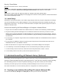
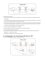
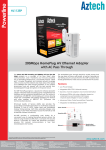
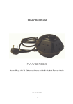
User Manual
PL200E
200Mbps Nano HomePlug AV
Safety
FCC
This equipment has been tested and found to comply with Part 15 Class B of the FCC Rules. Operation is subject
to the following two conditions:
(1) This device may not cause harmful interference
(2) This device must accept any interference received, including interference that may cause undesired operation.
CE
This equipment is in compliance with the requirements of the following regulations: CE Mark, 89/336/EEC
RoHS
This product is RoHS compliant.
Table of Contents
1 HomePlug Powerline .................................................................................................................................. 4 1.1 1.2 1.3 Introduction ................................................................................................................................................... 4 System Diagram ........................................................................................................................................... 4 Casing Details .............................................................................................................................................. 5 1.4 Initial Setup ................................................................................................................................................... 6 2 Front Casing ............................................................................................................................................................................................ 5 Status Lights ........................................................................................................................................................................................... 5 Bottom Casing ......................................................................................................................................................................................... 5 Security / Reset Button ........................................................................................................................................................................... 6 Connect the HomePlug AV Ethernet Bridge to a Computer or Modem/Router ...................................................................................... 6 Individual HomePlug AV Network Setup (Optional) ................................................................................ 6 2.1 2.2 2.3 Creating a new individual HomePlug AV network (Network AB) .................................................................. 6 Adding Bridge C to existing Network AB (Network ABC) ............................................................................. 7 Removing Bridge B from Bridge A & C Network and join with Bridge D & E (Network BDE) ....................... 8 3 Troubleshooting and Disclaimer ............................................................................................................... 8 4 Specification ............................................................................................................................................. 10 1 HomePlug Powerline
HomePlug Powerline is an excellent solution that can be used to extend your network. In the home or small office
building, use HomePlug Ethernet Bridges to link multiple locations without the need to run long Ethernet cables.
Combined with a broadband Fiber/DSL/Cable connection, every room with electrical power outlets will have easy
access to high-speed Internet connection. With the HomePlug AV speed of up to 200Mbps, this easy-to-setup solution can provide fast streaming HD movies, online multiplayer games, and other data intensive activities for
today’s HD Entertainment Center demand.
1.1 Introduction
Each HomePlug AV Ethernet Bridge allows you to connect one device that has an Ethernet port to a Powerline
network. In operation, the HomePlug AV Ethernet Bridge is completely transparent, and simply passes data between the Ethernet port and the Powerline network. Any Ethernet-enabled device may be connected to the
HomePlug AV Ethernet Bridge’s Ethernet port.
1.2 System Diagram
Add high-speed Internet access to any room in your home with this HomePlug AV Ethernet Bridge. You can
stream HD movies and music, play online multi-player games and much more.
Note: HomePlug AV Ethernet Bridge needs to pair with at least one other HomePlug AV compatible device such as
this one in order to create a working system.
1.3 Casing Details
Front Casing
The front casing contains 3 status lights: Power, PLC Link, and Ethernet Link.
Power Light
PLC Link Light
Ethernet Link Light
Status Lights
Power
On: This HomePlug Ethernet Bridge is receiving electrical power
Off: Power off
Flashing Green ( 1 second ON, 4 second OFF ) : Device in standby mode
PLC Link
The PLC (Powerline) Link light will indicate the overall speed of your network with 3 colors:
Red: Minimum connection indicates weak signal and slower network speed: less than 50Mbps
Orange: Normal signal with standard network speed: 50-99Mbps
Green: Excellent signal with optimal network speed: 100Mbps+
Off: No activity. This HomePlug Ethernet Bridge is not connected
Ethernet Link
Solid Green: 10/100 Mbps port linked
Off: Ethernet Link not active
Bottom Casing
The bottom casing contains a recessed Reset Button, a Security Button, and an Ethernet Port.
Security / Reset Button
Ethernet Port
Security / Reset Button
This button has dual functions : Security and Reset
Security
This function is designed to generate an individual HomePlug AV network group under multiple nodes environment.
Please refer to the optional Individual HomePlug AV Network Setup section below for more details.
Reset
This function is used to clear ALL data and restore ALL settings to the factory default values.
Note: The HomePlug AV Ethernet Bridge must be plugged in to restore it to factory defaults. Hold the Reset button
until the status lights begin to flash.
1.4 Initial Setup
HomePlug is a plug and play device; user is able to plug and play without any complex configuration and settings.
You can use HomePlug AV nano Ethernet Bridge to connect networkable devices like computers and game consoles directly to each other. You can also connect devices like a computer or Blu-ray Disc™ player to a router or
modem for Internet access.
Connect the HomePlug AV Ethernet Bridge to a Computer or Modem/Router
1. Plug one end of the Ethernet Cable into the Ethernet Port on the bottom of the HomePlug AV Ethernet Bridge
2. Plug the HomePlug AV Ethernet Bridge into a AC Wall Power Outlet near the device you want to connect
Warning: Do not plug this HomePlug AV Ethernet Bridge into a powerstrip that has surge protection. Doing so
will degrade Powerline performance. For best performance, plug all HomePlug AV Ethernet Bridges directly into a wall outlet.
3. For connecting to a computer: Plug the other end of the Ethernet Cable into an OPEN Ethernet Port located on
your computer.
4. For connecting to a Modem or Router for Internet access: Plug the other end of the Ethernet Cable into an
OPEN Ethernet Port on your Modem or Router.
5. Make sure that the PLC Link light on each HomePlug AV nano Ethernet Bridge turns solid green.
6. Your HomePlug AV nano Ethernet Bridges are now connected forming a HomePlug AV network.
7. To enter standby mode for this device, double click the security/reset button in within 1 second.
8. To exit standby mode for this device, press the security/reset button once.
2 Individual HomePlug AV Network Setup (Optional)
All HomePlug AV Ethernet Bridges ship with a default security key so they will automatically link to all other
HomePlug AV Ethernet Bridges sharing the same electrical lines. If there are other HomePlug AV Ethernet Bridges in the building (such as in an office or apartment building), you may want to create your own individual
HomePlug AV network group so other HomePlug AV Ethernet Bridges cannot connect to your network.
This section describes how to use the Security button for configuration in the following situations:
2.1 Creating a new individual HomePlug AV network (Network AB)
Two unassociated Bridges (Bridge A and Bridge B) are forming a new network—Network AB
The procedure is as follows:
1. Press and hold the Security button on Bridge A for 10~15 seconds, then release. Once released, the Power
light will flash.
The password to Bridge A has just been erased and random security key has been generated. It must now be
linked to your network to adopt the new network security key.
2. Press and hold the security button on Bridge B for 10~15 seconds and release it when the Power light flashes.
The password to Bridge B has just been erased and random security key has been generated. It must now be
linked to your network to adopt the new network security key.
3. Currently, Bridge A and Bridge B are not networked
4. Press and hold the Security button on Bridge A for 1~3 seconds then release.
5. The Power light on Bridge A starts to flash.
6. Within 120 seconds after the Power light on Bridge A starts to flash, press and hold the Security button on
Bridge B for 1~3 seconds then release.
7. Both Bridge A and Bridge B are now networked together.
2.2 Adding Bridge C to existing Network AB (Network ABC)
One unassociated Bridge C is added to an existing Network AB.
The procedure is as follows:
8. Press and hold the Security button on Bridge C for 10~15 seconds, then release. Once released, the Power
light will flash.
The password to Bridge C has just been erased and random security key has been generated. It must now be
linked to your network to adopt the new network security key.
9. Press and hold the security button on Bridge A for 1~3 seconds. The Power light on Bridge A starts to flash.
10. Within 120 seconds after the Power light on Bridge A starts to flash, press and hold the security button on
Bridge C for 1~3 seconds then release.
11. Bridge A, Bridge B and Bridge C are now networked to each other.
2.3 Removing Bridge B from Bridge A & C Network and join with Bridge D &
E (Network BDE)
The procedure is as follows:
1. Press and hold the Security button on Bridge B for 10~15 seconds, then release. Once released, the Power
light will flash.
The password to Bridge B has just been erased and removes itself from Bridge A & C.
2. Press and hold the Security button on Bridge D for 1~3 seconds.
3. Within 120 seconds after the Power light on Bridge D starts to flash, press and hold the Security button on
Bridge B for 1~3 seconds then release.
4. Bridge B and Bridge D are now connected to each other, which in turn becomes part of Network BDE.
3 Troubleshooting and Disclaimer
If your HomePlug AV nano Ethernet Bridges have difficulty communicating with each other, check the following:
• Try power cycling the unit by unplugging it from the wall for 10 seconds and plugging it in again.
• Hold the security/reset button down for more than 15 seconds to reset to default setting. The HomePlug AV
nano Ethernet Bridge’s light will flash, the units will reset and attempt to link using default factory settings.
• Try plugging the HomePlug AV nano Ethernet Bridge into an adjacent plug.
• HomePlug AV Ethernet Bridges work better when plugged directly into the wall outlet. Connecting these Ethernet Bridges to a power strip or surge protector may degrade network performance or completely stop network
signals.
• This HomePlug AV nano Ethernet Bridge should not be used on GFI protected outlets as some outlets will filter
out HomePlug Powerline signal.
• This HomePlug AV nano Ethernet Bridge should not be used in areas with excessive heat.
• Certain florescent or incandescent lights are noise sources on the electrical and can degrade performance.
• If your building has more than one circuit breaker box, your HomePlug AV Ethernet Bridges may not be able to
connect between the different circuit breaker boxes. In this case, connect one HomePlug AV Ethernet Bridge to
a power outlet located on each of the circuit boxes. Connect Ethernet cable between each of the HomePlug AV
Ethernet Bridges to link the different circuits together. This will allow the HomePlug AV Ethernet Bridges from
different circuit breaker boxes to connect.
4 Specification
Main Chipset
Qualcomm QCA6410
Computer Interface
IEEE802.3 ; IEEE802.3u
Data PHY Rate
Up to 200 Mbps
Standards
HomePlug AV
Network Interface
One RJ-45 (10/100Base-T Ethernet)
One 200Mbps Power Line Port supporting co-existence with HomePlug 1.0
(14/85Mbps)
Security
128-bit AES Link Encryption with Key Management
Frequency Band
2-28 Mhz
Modulation Schemes
OFDM Symbol Modulation on Line synchronization
1024/256/64/16/8—QAM, QPSK, BPSK, ROBO Carrier Modulation
Additional Protocols
Mix of TDMA and CSMA/CA channel access scheme; CO device generates a
periodic beacon carrier for channel access scheme
Operation Range
Estimated range of 300 meters in wall power lines
Cabling
100Base-T ; Cat. 5 UTP Cable
Operating Temperature
0° C to 40° C ambient temperature
Storage Temperature
-20° C to 70° C ambient temperature
Humidity
10% to 90% maximum (non-condensing)
Power Input
100 ~ 240V @ 50/60Hz Internal
Housing
Plastic (98mm x 63mm x 28mm)
Status Lights
Power: On/Off/Flashing 1 second ON, 4 seconds OFF (Standby Mode)
PLC(Powerline) Link: Red/Orange/Green/Off
Ethernet Link: Solid/Off
Certifications
HomePlug AV Powerline Certification
FCC Class B / CE Mark