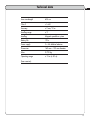
1
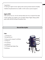
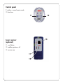
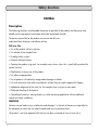
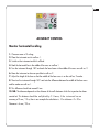
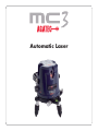
Automatic Laser
Table of contents
2
General description
Case
Control panel
Laser receiver
First steps
Horizontal alignment
Vertical alignment
Plumb beam
3
Safety directions
General
Limits of Use
Responsibilities
Hazards of Use
Laser Classification
Accuracy control
8
Warranty
14
Technical data
15
EN
Congratulations!
On choosing this Agatec instrument. Agatec provides measuring instruments of precision and quality.
Contributions from professional end users enable us to offer innovative, easy-to-use equipment.
Agatec MC3
Professional laser lines/cross with ultra visible laser beams due to the use of powerful laser diodes.
Automatic levelling using a pendulum system with magnetic damper. Magnetic damping enables
greater stability and faster levelling of the pendulum system.
General description
Case
1. vertical laser exit
2. horizontal laser exit
1
4
2
5
3. locking system for transport & on-off button
4. rotating case
5. fine adjustment
3
6. adjustable feet
7. 5/8 threaded tripod adaptor fitting
8. plumb beam
6
7
5
8
3
Control panel
9. outdoor = manual receiver mode
10. laser lines
9
13
Laser receiver
(optional)
11. on-off button
12. audible signal on or off
13. receiver area
11
12
4
10
EN
IMPORTANT!
Read the instructions for use carefully before using the instrument. Keep them in a safe place for
consultation when necessary.
1. Whether on or off, keep the instrument out of reach of children.
2. This equipment is a high quality precision instrument which must be handled with care.
3. Take care to avoid jolts and vibration.
4. After use, always replace the instrument in its carrying case.
5. Make sure that the case and instrument are dry; otherwise condensation may occur in the
apparatus.
6. Make sure that the windows are free of dirt, and clean them using a soft cloth and a glass
cleaning product only.
7. Always use the locking device during transportation.
8. Regularly inspect the accuracy of the instrument, especially when starting any major
square-setting work. You have sole responsibility for the accuracy of your work.
9. Do not use any optical equipment such as a magnifying glass to view the laser beam,
and take care to remove all reflecting objects to avoid damage to the eye.
10. Locate the laser in such a way that it is not possible for any person to look at the laser beam
(intentionally or otherwise).
11. Under no circumstances take the instrument apart, since this may expose you to
powerful laser radiation.
12. The laser is only to be used for the projection of laser lines.
13. Do not use the instrument in rain or near flammable materials.
14. Technical modification or alterations to the instrument may be carried out without prior notice.
15. The manufacturer's responsibility shall in no case exceed the value of the costs of repair or
replacement of the instrument.
16. Respect the environment and do NOT discard the instrument or batteries in household waste.
Take them to a recycling centre.
5
First steps
• Remove any protective films where applied.
• Open the battery compartment and insert batteries, taking care to observe the indicated polarity.
• Turn the transit locking system (3) to the "ON" position. The pendulum levelling mechanism is thus
released, and the instrument is able to align itself on its own. Make sure that the instrument is not
on too much of a slope (within 3°). If the slope of the instrument should exceed 3°, the lasers will
flash or will go out automatically.
• Use the adjustable feet (6) or locate the tripod so that the air-bubble is within the instrument's levelling range. NB: the accuracy of the instrument depends on the proper centralisation of the air-bubble. Max. 2 mm/10 m.
Horizontal alignment
• After disengagement of the pendulum locking system, and provided the instrument is within its
levelling range, the air-bubble is automatically at the horizontal level.
• The horizontal line may be activated or deactivated using the "H" butto).
• 3 laser beams enable a 360° horizontal line to be obtained.
• If possible, it is recommended that the horizontal line should be placed at working height.
This will improve the quality of your work.
• NB: laser lines and crosses can only be used on tripods which are adjustable in
height, such as cranked or telescopic tripods.
• Use the rotating case (4) to position the horizontal line.
• If the workplace is very brightly lit, e.g. out of doors, it may be necessary to use the laser
receiver.
6
EN
Vertical alignment
• After disengagement of the pendulum locking system, and provided the instrument is within its
levelling range, the vertical laser lines can be activated using button "L". These are mutually
at right angles (90°).
• Automatic levelling means that the laser lines are perfectly vertical and at right angles to the
horizontal laser line.
• The rotating case (4) and fine adjustment (5) can be used for positioning the vertical line.
• The fine adjustment (5) enables the laser beam to be located quickly and accurately on your
marker at large distances.
• Owing to the powerful laser diode and projection at an obtuse angle, the laser beam is visible
behind the instrument and a laser cross appears on the ceiling. The lower the instrument is located
and the nearer it is to the wall, the longer the laser beam. E.g. during placing of the wall.
• If the workplace is very brightly lit, e.g. out of doors, it may be necessary to use the laser
receiver.
Plumb beam
• The plumb beam (8) is visible as soon as a vertical laser is activated.
• In certain situations, use the plumb beam (8) to facilitate positioning of the vertical laser beam
or to describe right angles.
• E.g. if a parallel line needs to be projected onto the wall or onto the ceiling. Start by placing
the instrument with its plumb beam onto the first marker. Then turn the vertical line as far as marker
No. 2. Use the fine adjustment (5) to make everything correspond more easily and quickly.
• The plumb beam (8) is at right angles to the vertical laser cross on the ceiling. This is ideal for
squaring lighting points or describing walls.
7
Safety directions
GENERAL
Description
The following directions should enable the person responsible for the product, and the person who
actually uses the equipment, to anticipate and avoid operational hazards.
The person responsible for the product must ensure that all users
understand these directions and adhere to them.
Adverse Use
• Use of the product without instruction.
• Use outside of the intended limits.
• Disabling safety systems.
• Removal of hazard notices.
• Opening the product using tools, for example screw- driver, unless this is specifically permitted for
certain functions.
• Modification or conversion of the product.
• Use after misappropriation.
• Use of products with obviously recognizable damages or defects.
• Use with accessories from other manufacturers without the prior explicit approval of Agatec.
• Inadequate safeguards at the work site, for example when using on or near roads.
• Deliberate dazzling of third parties.
• Controlling of machines, moving objects or similar monitoring application without additional
control and safety installations.
WARNING
Adverse use can lead to injury, malfunction and damage. It is the task of the person responsible for
the equipment to inform the user about hazards and how to counteract them.
The product is not to be operated until the user has been instructed on how to work with it.
8
EN
LIMITS OF USE
Environment
Suitable for use in an atmosphere appropriate for permanent human habitation: not suitable for use in
aggressive or explosive environments.
DANGER
Local safety authorities and safety experts must be contacted before working in hazardous areas,
or in close proximity to electrical installations or similar situations by the person in charge of the product.
RESPONSIBILITIES
Manufacturer of the product
Agatec SAS, 21, boulevard Littré, F-78600 Le Mesnil Le Roi, hereinafter referred to as Agatec, is
responsible for supplying the product, including the user manual and original accessories, in a
completely safe condition.
Manufacturers of non Agatec accessories
The manufacturers of non Agatec accessories for the product are responsible for developing,
implementing and communicating safety concepts for their products, and are also responsible for
the effective- ness of those safety concepts in combination with the Agatec product.
Person in charge of the product
The person in charge of the product has the following duties
• To understand the safety instructions on the product and the instructions in the user manual.
• To be familiar with local regulations relating to safety and accident prevention.
• To inform Agatec immediately if the product and the application becomes unsafe.
WARNING
The person responsible for the product must ensure that it is used in accordance with the instructions.
This person is also accountable for the training and the deployment of personnel who use the
product and for the safety of the equipment in use.
9
HAZARDS OF USE
WARNING
The absence of instruction, or the inadequate imparting of instruction, can lead to incorrect or
adverse use, and can give rise to accidents with far-reaching human, material, financial and
environmental conse- quences.
Precautions:
All users must follow the safety directions given by the manufacturer and the directions of the person
respon- sible for the product.
CAUTION
Watch out for erroneous measurement results if the product has been dropped or has been misused,
modified, stored for long periods or transported.
Precautions:
Periodically carry out test measurements and perform the field adjustments indicated in the user
manual, particularly after the product has been subjected to abnormal use and before and after
important measurements.
WARNING
If the product is used with accessories, for example masts, staffs, poles, you may increase the risk of
being struck by lightning.
Precautions:
Do not use the product in a thunderstorm.
WARNING
Inadequate securing of the working site can lead to dangerous situations, for example in traffic,
on building sites, and at industrial installations.
Precautions:
Always ensure that the working site is adequately secured. Adhere to the regulations governing
safety and accident prevention and road traffic.
CAUTION
If the accessories used with the product are not properly secured and the product is subjected to
mechanical shock, for example blows or falling, the product may be damaged or people may
sustain injury.
10
EN
Precautions:
When setting-up the product, make sure that the accessories are correctly adapted, fitted, secured,
and locked in position. Avoid subjecting the product to mechanical stress.
CAUTION
During the transport, shipping or disposal of batteries it is possible for inappropriate mechanical
influences to constitute a fire hazard.
Precautions:
Before shipping the product or disposing of it, discharge the batteries by running the product until
they are flat. When transporting or shipping batteries, the person in charge of the product must
ensure that the applicable national and international rules and regulations are observed.
Before transportation or shipping contact your local passenger or freight transport company.
WARNING
High mechanical stress, high ambient tempera- tures or immersion into fluids can cause leackage,
fire or explosions of the batteries.
Precautions:
Protect the batteries from mechanical influences and high ambient temperatures. Do not drop or
immerse batteries into fluids.
WARNING
Short circuited battery terminals can overheat and cause injury or fire, for example by storing or
transporting in pockets if battery terminals come in contact with jewellery, keys, metallized paper or
other metals.
Precautions:
Make sure that the battery terminals do not come into contact with metallic objects.
CAUTION
During the operation of the product there is a hazard of
squeezing extremities by moving parts.
Precautions:
Keep extremities in a safe distance from the moving parts.
WARNING
If the product is improperly disposed of, the following can happen:
• If polymer parts are burnt, poisonous gases are produced which may impair health.
11
• If batteries are damaged or are heated strongly, they can explode and cause poisoning,
burning, corrosion or environmental contamination.
• By disposing of the product irresponsibly you may enable unauthorized persons to use it in
contravention of the regulations, exposing themselves and third parties to the risk of severe injury and
rendering the environment liable to contamination.
Precautions:
The product must not be disposed with household waste. Dispose of the product
appropriately in accordance with the national regulations in force in your country.
LASER CLASSIFICATION
General
The following directions (in accordance with the state of the art - international standard IEC 60825-1
(2007-03) and IEC TR 60825-14 (2004-02)) provide instruction and training information to the
person responsible for the product and the person who actually uses the equipment, to anticipate
and avoid operational hazards.
The person responsible for the product must ensure that all users understand these directions and
adhere to them.
Products classified as laser class 1, class 2 and class 3R do not require
• laser safety officer involvement,
• protective clothes and eyewear,
• special warning signs in the laser working area if used and operated as defined in this user
manual due to the low eye hazard level.
Products classified as laser class 2 or class 3R may cause
dazzle, flash blindness and afterimages, particularly under low ambient light conditions.
12
EN
ACCURACY CONTROL
Monitor horizontal levelling
1. Choose a room ±10 m long
2. Place the instrument next to wall no. 1.
3. Switch on the instrument and let it self-level.
4. Mark the horizontal line in the middle of the cross on wall no 1.
5. Turn the instrument through 180° and mark the laser beam in the middle of the cross on wall no. 2.
6. Move the instrument as close as possible to wall no. 2.
7. Adjust the height of the laser so that the middle of the laser cross is on the wall no. 2 marker.
8. Then turn the instrument through 180° and note the difference between the middle of the laser cross
and the marker on wall no. 1.
9. This difference should not exceed 2 mm.
10. NB: The tolerance depends on the distance of the walls between which the inspection has been
carried out. This distance should be multiplied by 2. Hence, if the instrument has an
accuracy of 2 mm / 10 m, then in our example the calculation is: 10 m distance x 2 = 20 m.
Tolerance is 4 mm / 20 m.
13
Horizontal laser line
1. Place the instrument approximately 5 m from a wall.
2. Switch on the instrument and let it self-level.
3. Mark the middle of the laser cross.
4. Turn the horizontal laser line 2.5 m to the left or to the right.
5. Note the tolerance between the marker and the position of the laser line.
6. This should be 2 mm in our example.
Vertical laser line
1. Place the instrument approximately 5 m from a wall.
2. Place a 2 m long plumb-line against the wall.
3. Switch on the instrument and let it self-level.
4. Place the vertical laser line on the plumb-line.
5. This should be 1.5 mm in our example.
NB: If your instrument does not reach the required tolerance, it should be returned to your service centre
or to your reseller for service. Repairs carried out by unauthorised personnel will
automatically invalidate the guarantee.
Warranty
This product is subject to the terms and conditions set out in the International Limited Warranty which you
can download from the Agatec home page at www.agatec.com or collect from your Agatec distributor.
The foregoing warranty is exclusive and is in lieu of all other warranties, terms or conditions, express or
implied, either in fact or by operation of law, statutory or otherwise, including warranties, terms or
conditions of merchantability, fitness for a particular purpose, satisfactory quality and non-infringement,
all of which are expressly disclaimed.
14
Technical data
Laser wavelength
635 nm
Class II
<1 mW
Accuracy
± 2 mm/10 m
Levelling range
± 3°
Levelling
Magnetic pendulum system
Battery life
12 hr
Power supply
3 x AA alkaline batteries
Dimensions
160 mm x 100 mm diameter
Mass
0.700 kg
Operating range
± 15 m (± 50 m)
EN
(laser receiver)
15