1
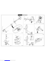
RBCGM25SS TRIMMER / BRUSHCUTTER OPERATOR’S MANUAL (Original Instructions) Important! It is essential you read the instructions in this manual before starting and operating this machine. Subject to technical modifications. Downloaded from www.Manualslib.com manuals search engine Downloaded from www.Manualslib.com manuals search engine Downloaded from www.Manualslib.com manuals search engine English (Original Instructions) GENERAL SAFETY WARNINGS Dangerous Environments. To avoid falling, do not use the product in damp or wet locations. Controlling the Product. During carburetor adjustments the cutting attachment may spin. Therefore, you should wear protective equipment and observe all safety instructions when adjusting the carburetor. For products equipped with a clutch, be sure the cutting attachment stops turning when the engine idles. When the product is turned off, make sure the cutting attachment has stopped before setting down the product. Use the Right Product. Use the product for the intended purpose only. Save these instructions. Refer to them frequently and use them to instruct others who may use this power tool. If you loan someone this power tool, loan them these instructions also. WARNING Read and understand all instructions. Failure to follow all instructions may result in serious personal injury as well as damage to the product. Physical Condition of the Operator. Do not operate this product when tired, ill or under the influence of alcohol, drugs or medication. Clothing Requirements. Always wear long heavy pants, boots and gloves. Do not wear loose clothing, jewelry, short pants, sandals or go barefoot. Secure hair so that it is above shoulder level to avoid entanglement in moving parts. Protective Accessories Requirements. Wear eye and hearing protection when operating this product. Before use, inspect the condition of the trimmer. Replace damaged parts. Check for fuel leaks. Make sure all fasteners are in place and secure. Replace cutting attachment parts that are cracked, chipped or damaged in any way. Make sure the cutting attachment is properly installed and securely fastened. Be sure the cutting attachment shield is properly attached and in the position recommended by the manufacturer. Use only flexible, non-metallic line recommended by the manufacturer. For example, never use wire or wirerope, which can break off and become a dangerous projectile. Proper Stance. Keep firm footing and balance. Do not overreach. Keep the cutting attachment below waist level. Keep all parts of your body away from the rotating cutting attachment and hot surfaces. Exhaust Gases. Never start or run the product inside a closed room or building; breathing exhaust fumes can cause illness or death. Fueling. Mix and pour fuel outdoors where there are no sparks and flames. Slowly remove the fuel cap only after stopping the engine. Do not smoke while fueling or mixing fuel. Wipe spilled fuel from the product. Move at least 30ft. (9m) away from the fueling source and site before starting the engine. Work Area. Clear the area to be cut before each use. Remove all objects, such as rocks, broken glass, nails, wire or string, that can be thrown or become entangled in the cutting attachment. Clear the area of children, bystanders and pets. At a minimum, keep all children, bystanders and pets outside a 50 ft. (15 m) radius. Because there still may be a risk of injury to bystanders from thrown objects. Bystanders should be encouraged to wear eye protection. If you are approached while operating the product, stop the engine and the cutting attachment. SPECIFIC SAFETY RULES FOR BRUSHCUTTER AND BLADE WARNING Extreme care must be taken when using blades to ensure safe operation. Read the safety information for safe operation using the blade, refer to "Specific Safety Rules for Brushcutter and Blade Use" earlier in this manual. Always hold brushcutter with both hands when operating. Use a firm grip on both handles. Maintain your grip and balance on both feet. Position yourself so that you will not be drawn off balance by the kick-back reaction of the cutting blade. Inspect and clear the area of any hidden objects such as glass, stones, concrete, fencing, wire, wood, metal, etc. Never use blades near footpaths, fencing, posts, buildings or other immovable objects. Never use a blade after hitting a hard object without first inspecting it for damage. Do not use if any damage is detected. The unit is used as a scythe, cutting from the right to the left in a broad sweeping action from side to side. 2 Downloaded from www.Manualslib.com manuals search engine English (Original Instructions) SYMBOLS The following symbols are located on labels on the attachment shaft. Please study them and learn their meaning. Proper interpretation of these symbols will allow you to operate the tool better and safer. SYMBOL NAME DESIGNATION/EXPLANATION Safety Alert Precautions that involve your safety. Read The Operator’s Manual Read the operatorʼs manual before starting or operating this product. Failure to follow operating instructions and safety precautions in the operatorʼs manual can result in serious injury. Eye and Ear Protection Thrown objects can cause severe eye injury. Wear eye protection when operating this product. Wear hearing protection during extended periods of operation. Thrown Objects Thrown objects can cause severe injury. Wear protective clothing and boots. Keep Bystanders Away Keep all bystanders, especially children and pets, at least 50 feet (15m) from the operating area. The following signal words and meanings are intended to explain the levels of risk associated with this product. SYMBOL SIGNAL MEANING DANGER: Indicates an imminently hazardous situation, which, if not avoided, will result in death or serious injury. WARNING: Indicates a potentially hazardous situation, which, if not avoided, could result in death or serious injury. CAUTION: Indicates a potentially hazardous situation, which, if not avoided, may result in minor or moderate injury. CAUTION: (Without Safety Alert Symbol) Indicates a situation that may result in property damage. 3 Downloaded from www.Manualslib.com manuals search engine English (Original Instructions) SPECIFICATIONS Weight without fuel and trimmer head 5.31 Kg Weight without fuel with trimmer head 5.61 Kg Fuel tank volume 620 cm3 Cutting swath 457 mm Diameter of cutting line 2.4 mm Engine displacement 25.4 cc Maximum engine performance (in accordance with ISO 8893) 0.9 kW Maximum rotational frequency of the spindle 10000 min-1 Engine speed (rotational frequency) at recommended max. spindle rotational frequency 12000 min-1 Engine speed (rotational frequency) at idle 4. Guide recess 5. Front handle 14.Grass deflector 23. Trimmer line 24. Trimmer head FIGURE 2 5. Front handle 6. Securing bolts 7. Bracket FIGURE 3 8. Guard mounting bracket 9. Blade guard 10. Slot 11. Guard screws 12.Threaded mounting plates 13.Locking tabs 14.Grass deflector FIGURE 4 15. On/Off switch 16. Throttle lock out button 17. Throttle trigger 18. Primer bulb 19. Starter grip 2600-3200 min-1 Fuel consumption (in accordance with ISO 8893) at max. engine performance 0.54 kg/h Specific fuel consumption (in accordance with ISO 8893) at max. engine performance 0.50 kg/h FIGURE 11 20. Foam air filter 21. Air filter cover 22. Cover securing knob FIGURE 12 25. Spark plug boot 26. Spark plug Vibration level idling Left handle Right handle 6.4 m/s2 14.9 FIGURE 13 27. Spark arrester m/s2 FIGURE 14 28.Bump head spring 29. Bump head securing bolt 30.Cutting head housing 31.Blade flange washer 32.Gearbox 33.Shaft locking pin 34.Socket wrench 35.Cupped washer 36.Blade nut 37.Blade 38.Spanner 39.Gear shaft 40.Bump head cover 41.Bump knob 42. Line spool 43.Drive shaft adaptor Vibration level racing Left handle 5.8 m/s2 Right handle 3.7 m/s2 Sound pressure level (in accordance with EN ISO1806:1997. ISO 7917:1987) Sound power level (in accordance with ISO 10884) 98 LPA(dBA) 113 LWA(dBpA) DESCRIPTION FIGURE 1 1. Upper shaft 2. Knob 3. Button 4 Downloaded from www.Manualslib.com manuals search engine English (Original Instructions) ASSEMBLY INSTALLING THE REEL EASY LINE TRIMMER HEAD (FIG. 10) Stop the engine and disconnect the spark plug wire. Remove currently installed line trimmer head or cutting blade. Open the Reel Easy Line Trimmer Head by depressing the latches on each side. The contents of the line trimmer head are spring loaded, so keep your other hand over the line trimmer head cover while depressing the latches. (image 3) Remove the line trimmer head cover, bump knob, and line spool and set aside. Place the cutting head housing on the drive shaft. Make sure the housing is fully seated. Install the hex bolt to secure the line trimmer head to the drive shaft. Tighten by using the hex-shaped opening on the inside of the bump knob. Note: Only use the bump knob to tighten the bolt. The use of other tools may allow over tightening of the bolt, which could damage the line trimmer head. (image 4) ATTACHING THE POWER HEAD TO THE TRIMMER ATTACHMENT (FIG. 1) Follow these steps to connect the attachment to the upper shaft (item 1). Loosen the knob (item 2) by turning it counter clockwise. Align the button (item 3) on the attachment shaft with the guide recess (item 4) on the upper shaft. Slide the attachment shaft into the upper shaft until the attachment shaft clicks into place. Tighten the knob securely by turning it clockwise. Removing the Attachment from the Upper Shaft. Follow these steps to remove the attachment from the upper shaft. Loosen the knob by turning it counterclockwise. Push the button while pulling out the attachment. ATTACHING THE FRONT HANDLE (FIG. 2) Remove the securing bolts (item 6) and bracket (item 7) from the front handle (item 5). Install the front handle (item 5) onto the upper shaft (item 1). Note: The front handle should tilt slightly towards the operator when correctly fitted. Reinstall the bump head spring into the line trimmer head and push down to seat. (image 5) Reinstall the line spool. Note: For the straight shaft attachment with the Reel Easy cutting head, the spool should be placed so “This side out for straight shaft” is visible on the line spool. Place the bolt through the front handle and securely tighten them into the captive nuts on the bracket (item 7). Note: Do no attempt to remove or modify the spacer, this spacer limits the upper position of the handle grip. Replace the bump knob by inserting it into the centre of the line spool. Replace the line trimmer head cover, aligning latches with openings in the line trimmer head. Press cover and line trimmer head together until both latches snap into openings securely. Install line as described in the next section of this manual. ASSEMBLY OF THE GUARD (FIG. 3) Attach the blade guard (item 9) to the guard mounting bracket (item 8); install the four screws (10-24 x 3/4in) from the top of the mounting clamp through the blade guard and into the threaded mounting plates (item 12). Using the Torx wrench supplied, tighten all four screws securely. INSTALLING LINE IN REEL EASY LINE TRIMMER HEAD (FIG. 10) Use 2.4mm diameter monofilament line. ATTACHING THE GRASS DEFLECTOR TO THE GUARD (FIG. 3) Note: When using the line trimming head, the grass deflector (item 14) must be attached to the blade guard (item 9). Carefully align the locking tabs on the grass deflector (item 13) with the the slots on the blade guard (item 10). Push the grass deflector towards the blade guard until the locking tabs click firmly into place. CAUTION The grass deflector is fitted with a line cut off blade. Take extra care when fitting the grass deflector to avoid contact with the sharp blade. 5 Downloaded from www.Manualslib.com manuals search engine Stop the engine and disconnect the spark plug wire. Cut one piece of line approximately 6.0 meters in length. Rotate the bump knob on line trimmer head until line on the centre of the bump knob aligns with arrows on top of line trimmer head. (image 6) Insert one end of line into eyelet located on the side of the line trimmer head and push until line comes out through the eyelet on the other side. Continue to push line through the line trimmer head until the middle section of the line is inside the line trimmer head and line outside the line trimmer head is evenly divided on each side. (images 7-8) Rotate the knob on the line trimmer head to wind the line. If using a straight shaft attachment, the knob should be rotated clockwise. English (Original Instructions) CONVERTING FROM BRUSH CUTTER TO LINE TRIMMER (FIG. 15) Wind the line until approximately 20cm remains protruding from the line trimmer head. Replace the spark plug boot. REMOVING THE BLADE Insert the holding pin through the slot in the upper flange washer and the gear head. Turn the blade nut clockwise to remove. Remove the cupped washer and the blade. Remove the upper flange washer from the gear shaft and retain for the line trimmer head installation. Attach the grass deflector to the blade guard. Refer to "ATTACHING THE GRASS DEFLECTOR TO THE GUARD" earlier in this manual. NOTE: Store the brush cutter parts together for later use. CONVERTING FROM LINE TRIMMER TO BRUSH CUTTER (FIG. 14) Stop the engine and disconnect the spark plug wire. REMOVING THE LINE TRIMMING HEAD Open the Reel Easy Line Trimmer Head by depressing the latches on each side. The contents of the line trimmer head are spring loaded, so keep your other hand over the line trimmer head cover while depressing the latches. Remove the bump head cover (item 40), bump knob (item 41), line spool (item 42) and spring (item 28) and set them aside. Use the hex-shaped opening on the inside of the bump knob (item 41) to remove the hex bolt (item 29) on the drive shaft (item 43) in a clockwise direction and set aside. Remove the cutting head housing (item 30). Align the slot in the upper flange washer (item 31) with the hole in the gear head (item 32). Insert the holding pin (item 33) through the slot in the upper flange washer and the hole in the gear head. Using the 16mm socket wrench (item 34) supplied, turn the drive shaft adaptor (item 43) clockwise to remove it from the gear shaft (item 39). Remove the upper flange washer from the gear shaft and retain for blade installation. Remove the grass deflector by pushing in on the three locking tabs while pulling on the grass deflector to separate from the blade guard. (image 6) NOTE: Store the line trimmer head parts and grass deflector together for later use. INSTALLING THE REEL EASY LINE TRIMMER HEAD Refer back to instructions listed earlier in this manual. OPERATION FUEL AND REFUELING Handling the fuel safely Always handle fuel with care, it is highly flammable. Always refuel outdoors where there are no sparks and flames. Do not inhale fuel vapors. Do not let petrol or oil come in contact with your skin. Keep petrol and oil away from the eyes. If petrol or oil comes in contact with the eyes, wash them immediately with clean water. If irritation is still present, see a doctor immediately. Clean up spilled petrol immediately. MIXING THE FUEL This product is powered by a 2-stroke engine and requires pre-mixing petrol and 2-stroke oil. Pre-mix unleaded petrol and 2-stroke engine oil in a clean container approved for petrol. This engine is certified to operate on unleaded petrol intended for automotive use with an octane rating of 87 ([R + M] / 2) or higher. Do not use any type of pre-mixed petrol / oil from fuel service stations, this includes the pre-mixed petrol / oil intended for use in mopeds, motorcycles, etc. Use synthetic 2-stroke oil only. Do not use automotive oil or 2-stroke outboard oil. Mix 2% synthetic 2-stroke oil into the petrol. This is a 50:1 ratio. Mix the fuel thoroughly and also each time before fueling. Mix in small quantities. Do not mix quantities larger than usable in a 30 day period. Synthetic 2-stroke oil containing a fuel stabilizer is recommended. INSTALLING THE BLADE Place the upper flange washer over the gear shaft with the hollow side towards the blade guard. Centre blade (item 37) on the upper flange washer, making sure the blade sits flat. Install the cupped washer (item 35) with the raised centre away from the blade. Install and hand tighten the blade nut in a counterclockwise direction (item 36). The blade (item 37) turns counterclockwise from the operator’s position during operation. Insert the holding pin through the slot in the upper flange washer and the hole in the gear head (item 32). Using the wrench (item 38) supplied, turn the blade nut (item 36) counterclockwise. Tighten nut securely. 6 Downloaded from www.Manualslib.com manuals search engine English (Original Instructions) FILLING THE TANK Clean surface around fuel cap to prevent contamination. Loosen fuel cap slowly to release pressure and to keep fuel from escaping around the cap. Carefully pour fuel mixture into the tank. Avoid spillage. Prior to replacing the fuel cap, clean and inspect the gasket. Immediately replace fuel cap and hand tighten. Wipe up any fuel spillage. Move 9 m away from refueling site before starting engine. Note: It is normal for smoke to be emitted from a new engine during and after first use. 6. Pull the starter grip (item 19) with a quick firm and consistent upward motion (No more than 4x). 7. Set the choke lever to position B (Choke Open). 8. Hold down the throttle the lock-off button and squeeze the throttle trigger. 9. Pull the starter grip with a quick firm and consistent upward motion until the engine starts (No more than 6x). Note: If engine does not start, return to step 4 and repeat the steps. Note: When the engine starts, let it run for 30 seconds prior to operation. TO START A WARM ENGINE Follow these steps to start a warm engine. 1. Lay the product on a flat, bare surface. 2. Ensure the engine switch is in the I (ON) position (item 15). 3. Ensure the choke lever is set to position B (Choke Open). 4. Hold down the throttle lock-off button (item 16) and squeeze the throttle trigger (item 17). 5. Pull the starter grip with a quick firm and consistent upward motion until the engine starts (No more than 6x). Note: If engine does not start, return to step 4 on the "TO START A COLD ENGINE" and repeat the steps. WARNING Always shut off engine before fueling. Never add fuel to a machine with a running or hot engine. Move at least 9m from refueling site before starting engine. Do not smoke! 50:1 Petrol to Oil Mixing Chart 1 litre 2 litres 3 litres 4 litres 5 litres + + + + + 20 ml 40 ml 60 ml 80 ml 100 ml = = = = = STOPPING THE PRODUCT Release the throttle trigger. Hold down the engine switch to the O (OFF) position until the engine comes to a complete stop. 50: 1 (2%) OPERATING AS A LINE TRIMMER (FIG.6) Follow these steps to operate the straight shaft trimmer. WARNING Start the trimmer. Hold the trimmer at waist level with your right hand on the trigger handle and your left hand on the front handle. Place the product on the right side of your body with the engine behind and away from your body. Trim grass and weeds in a left-to-right motion with the line parallel to the ground. The product may throw objects during operation, causing injury to the operator or to bystanders. Always wear suitable eye protection, long heavy pants and boots while operating the product. STARTING THE PRODUCT (FIG. 4-5) Starting the product differs depending on whether the engine is cold or warm. Refer to the label on the air filter cover. TO ADVANCE THE CUTTING LINE (FIG.7) Follow these steps to advance the cutting line. TO START A COLD ENGINE Follow these steps to start a cold engine. 1. Lay the product on a flat, bare surface. 2. Ensure the engine switch is in the I (ON) position (item 15). 3. Push the primer bulb (item 18) approximately 10 times. 4. Set the choke lever to position A (Choke Closed). 5. Hold down the throttle lock-off button (item 16) and squeeze the throttle trigger (item 17). Start the trimmer. Tap the bump knob lightly on the ground while the motor is running. The line will only advance with the engine at full throttle. Do not hold the bump knob on the ground. Note: The line cutting blade on the safety guard will cut the line to the proper length. Note: To help prevent line tangle, tap only once to lengthen the line. If additional line is required, wait a 7 Downloaded from www.Manualslib.com manuals search engine English (Original Instructions) few seconds before retapping the bump knob. Do not allow the line to wear too short. Keep the cutting line at full length. WARNING Always wear safety goggles or safety glasses with side shields during tool operation. If operation is dusty, also wear a dust mask. OPERATING AS A BRUSHCUTTER (FIG. 8-9) WARNING WARNING Extreme care must be taken when using blades to ensure safe operation. Read the safety information for safe operation using the blade, refer to “Specific Safety Rules for Brushcutter and Blade Use” earlier in this manual. Before inspecting, cleaning, or servicing the machine, shut off engine, wait for all moving parts to stop, and disconnect spark plug lead and move it away from spark plug. Failure to follow these instructions can result in serious personal injury or property damage. TRI-ARC BLADE The TRI-ARC blade is suited only for pulpy weeds and vines. When the blade becomes dull, it can be turned over to extend the life of the blade. Do not sharpen the TRIARC blade. WARNING Neglected or poorly conducted maintenance may create additional hazards. Do not attempt to repair or maintain this product if you are not qualified to do so. If in doubt, return to a service centre for professional assistance. Hold the brushcutter with the right hand on the trigger handle and the left hand on the front handle. Keep a firm grip with both hands while in operation. Brushcutter should be held at a comfortable position with the trigger handle about hip height. Maintain your grip and balance on both feet. Position yourself so that you will not be drawn off balance by the kick-back reaction of the cutting blade. If using a shoulder strap adjust to position the brushcutter at a comfortable operating position. Shoulder straps are available as an accessory and may help to reduce operator fatigue. GENERAL MAINTENANCE Avoid using solvents when cleaning plastic parts. Most plastics are susceptible to damage from various types of commercial solvents and may be damaged by their use. Use clean cloths to remove dirt, dust, lubricant, grease. WARNING Do not at any time let brake fluids, petrol, petroleumbased products, penetrating lubricants, etc., come in contact with plastic parts. Chemicals can damage, weaken or destroy plastic which may result in serious personal injury. Exercise extreme caution when using the blade with this unit. Blade thrust is the reaction which may occur when the spinning blade contacts anything it cannot cut. This contact may cause the blade to stop for an instant, and suddenly “thrust” the unit away from the object that was hit. This reaction can be violent enough to cause the operator to lose control of the unit. Blade thrust may occur without warning if the blade snags, stalls or binds. This is more likely to occur in areas where it is difficult to see the material being cut. For cutting ease and safety, approach the weeds being cut from the right to the left. In the event that an unexpected object or woody stock is encountered, this could cause the blade thrust reaction. You can often make adjustments and repairs described in this manual. For other repairs, have the trimmer serviced by an authorised service dealer. CLEANING THE AIR FILTER (FIG. 11) A dirty air filter will cause starting difficulty, loss of performance, and shorten the life span of the engine. Check the air filter monthly. For best performance, replace the air filter at least once a year. MAINTENANCE Loosen the air filter cover by turning the cover securing knob (item 22) counterclockwise. Remove the air filter (item 20). Clean the foam filter element with warm soapy water. Rinse and let dry. NOTE: If the foam filter element is damaged, it should be replaced. WARNING When servicing, use only identical replacement parts. Use of any other parts may create a hazard or cause product damage. Apply a light coat of engine oil to the foam filter element, then squeeze it out. Reinstall the air filter. 8 Downloaded from www.Manualslib.com manuals search engine English (Original Instructions) NOTE: Make sure the filter is seated properly inside the cover. Installing the filter incorrectly will allow dirt to enter the engine, causing rapid engine wear. Run the engine until it stops. Clean all foreign material from the product. Store the product in a well-ventilated place that is inaccessible to children. Note: Keep the product away from corrosive agents such as garden chemicals. Important: Abide by all local and government regulations for the safe storage and handling of petrol. Reinstall the cover and tighten knob to secure. CHECKING THE FUEL CAP WARNING A leaking fuel cap is a fire hazard and must be replaced immediately. The fuel cap contains a non-serviceable filter and check valve. A clogged fuel filter causes poor engine performance. If performance improves when the fuel cap is loosened, the check valve may be faulty or the filter may be clogged. Replace the fuel cap if necessary. REPLACING THE SPARK PLUG (FIG. 12) This engine uses a Champion RCJ6Y or NGK BPMR7A spark plug. Use an exact replacement and replace annually. Follow these steps to replace the spark plug. Remove the spark plug boot (item 25). Loosen the spark plug (item 26) by turning it counterclockwise with a 16mm socket. Remove the spark plug. Hand thread the new spark plug, turning it clockwise. Tighten with a socket. Do not overtighten. CAUTION Be careful not to cross-thread the spark plug. Crossthreading will seriously damage the engine. CLEANING THE SPARK ARRESTER (FIG. 13) Follow these steps to clean the spark arrester. Locate the spark arrestor (item 27) through the hole on the muffler exit hole. Remove the spark arrestor using needle-nosed pliers. Clean the spark arrestor with a small wire brush. Replace the spark arrestor. STORING THE PRODUCT Storing the product differs depending on the amount of time it will be in storage. Follow these steps for short term product storage. Clean all foreign material from the product. Store the product in a well-ventilated place that is inaccessible to children. If you do not intend to use the product for more than one month, follow the storage procedures below. Drain all fuel from the tank into a container approved for petrol. Downloaded from www.Manualslib.com manuals search engine 9 English (Original Instructions) TROUBLE SHOOTING PROBLEM Engine will not start Engine does not reach full speed and emits excessive smoke Cutting line will not advance when using bump feed action POSSIBLE CAUSE SOLUTION 1. Switch set to the O (OFF) position. 1.Set switch to the I (ON) position. 2. No spark 2. Remove the spark plug. Reattach the spark plug cap and lay the spark plug on the metal cylinder. Pull the starter cord and watch for a spark at the spark plug tip. If there is no spark, repeat the test with a new spark plug. 3. No fuel 3. Push primer bulb until the bulb is full of fuel. If the bulb does not fill, the primary fuel delivery system is blocked. If the primer bulb fills, the engine may be flooded. (See next item.) 4. Flooded engine 4. Remove the spark plug. Turn the product so that the spark plug hole is aimed at the ground. Make sure the choke lever is set to position B and pull the starter cord 10 to 14 times. This clears excess fuel from the engine. Clean and reinstall the spark plug. With the throttle trigger fully depressed, pull the starter cord 3 times. If the engine does not start, set the choke lever to A and follow normal starting instructions. If the engine still fails to start, repeat the procedure with a new spark plug. 5. Starter cord is hard to pull 5. Contact an authorized service dealer. 1. Check oil fuel mixture 1. Use fresh fuel and the correct 2-stroke oil mix. 2. Air filter is dirty 2. Clean the air filter according to the instructions in the Maintenance section. 3. Spark arrestor screen is dirty 3. Contact an authorized service dealer. 1. Line welded to itself 1. Lubricate with silicone spray. 2. Not enough line on the spool 2. Install more line. 3. Line worn too short 3. Pull line while alternately pressing down on and releasing the bump knob. 4. Line tangled on spool 4. Remove line from spool and rewind. 5. Engine speed too slow 5. Advance line at full throttle. 6. Line spool installed back to front 6. Ensure the writing on the line spool is facing the correct way; THIS SIDE OUT FOR STRAIGHT SHAFT. Grass wraps around the trimmer 1. Cutting tall grass at ground level 1. Cut tall grass from the top down. head assembly and the attachment 2. Operating the product at part throttle 2. Operate the product at full throttle. shaft 1. Operating the product at part throttle 1. Operate the product at full throttle. Oil drips from muffler 2. Check oil/fuel mixture 2. Use fresh fuel and the correct 2-stroke oil mix. 3. Air filter is dirty 3. Clean the air filter according to the instructions in the Maintenance section. 10 Downloaded from www.Manualslib.com manuals search engine LIMITED WARRANTY (Original Instructions) TTI warrants this outdoor product to be free of defects in material and workmanship for 24 months from the date of purchase by the original purchaser, subject to the limitations below. Please keep your invoice as proof of date of purchase. This warranty is only applicable where the product is used for personal and non-commercial purposes. This warranty does not cover damage or liability caused by / due to misuse, abuse, accidental or intentional acts by user, improper handling, unreasonable use, negligence, failure by end user to follow operating procedures outlined in the user’s manual, attempted repair by non-qualified professional, unauthorised repair, modification, or use of accessories and/or attachments not specifically recommended by authorised party. Please see your local dealer for list of authorised service centres in your area. This warranty does not cover belts, brushes, bags, bulbs or any part which ordinary wear and tear results in required replacement during warranty period. This warranty does not cover transportation cost or consumable items such as fuses and batteries. This limited warranty is void if the product’s original identification (trade mark, serial number, etc.) markings have been defaced, altered or removed or if product is not purchased from an authorised reseller or if product is sold AS IS and / or WITH ALL FAULTS. Where permitted, the provisions of this limited warranty are in lieu of any other written warranty, whether express or implied, written or oral, including any warranty of MERCHANTABILITY OR FITNESS FOR A PARTICULAR PURPOSE. IN NO EVENT SHALL WE BE LIABLE FOR SPECIAL, INCIDENTAL, CONSEQUENTIAL OR INCIDENTAL DAMAGES. OUR MAXIMUM LIABILITY SHALL NOT EXCEED THE ACTUAL PURCHASE PRICE PAID BY YOU FOR THE PRODUCT. This warranty is applicable only in the European Union, Australia, and New Zealand. Outside these areas, please contact your authorised Ryobi dealer to determine if another warranty applies. Downloaded from www.Manualslib.com manuals search engine TECHTRONIC INDUSTRIES EMEA Medina House, Fieldhouse Lane, Marlow, Bucks SL7 1TB - United Kingdom RYOBI TECHNOLOGIES (UK) LIMITED Medina House, Fieldhouse Lane, Marlow, Bucks SL7 1TB - United Kingdom Tel: + 44 (0) 1628 894400 Fax: + 44 (0) 1628 894401 Technical Helpline : + 44 (0) 800 389 0305 TECHTRONIC INDUSTRIES FRANCE SAS Immeuble Le Grand Roissy Z.A. du Gué - 35 rue de Guivry 77990 Le Mesnil Amelot France Phone: + 33(0)1 60 94 69 70 Fax: + 33(0)1 60 94 69 79 RYOBI BELGIUM Avenue des Pâquerettes, 55 Zoning artisanal - bâtiment 5 B - 1410 Waterloo Belgique Tel : + 32(0) 2357 8140 Fax : + 32(0) 2357 8149 TTI ITALIA SRL Via Fratelli Gracchi, 39 20092 Cinisello Balsamo (MI) Italia Tel : + 39 02 37050440 Fax : + 39 02 37050444 TECHTRONIC INDUSTRIES IBERIA S.L Av. De la Industria, 52 Coslada – Madrid – España Tel: 91 485 12 10 TECHTRONIC INDUSTRIES SOUTH AFRICA CO. (PTY) LTD P.O Box 83888, South Hills, Johannesburg, 2136 South Africa TECHTRONIC OUTDOOR PRODUCTS TECHNOLOGY LIMITED 24/F, CDW Building, 388 Castle Peak Road, Tsuen Wan, Hong Kong Tel : + 852 2402 6888 TECHTRONIC INDUSTRIES CENTRAL EUROPE GMBH Itterpark 2 D-40724 Hilden Deutschland Tel: + 49 (0) 2103 960-0 Fax: + 49 (0) 2103 960-238 TECHTRONIC INDUSTRIES AUSTRALIA PTY LIMITED Building B, Rosehill Industrial Estate, 3 Shirley Street, Rosehill NSW 2142 Australia Tel: (02) 8892 1800 or 1300 361 505 Fax: 1800 807 993 TECHTRONIC INDUSTRIES (NZ) LIMITED 27 Clemow Drive, Mt Wellington PO Box 12-806, Penrose, Auckland New Zealand Tel: + 64 (0) 9 573 0230 Free Call: +64 0800 279 624 Fax: + 64 (0) 9 573 0231 A&M MIDDLE EAST FZCO P.O.Box 61254 Jedel Ali, Dubai United Arab Emirates Tel.: + 9714 8861399 Fax: + 9714 8861400 TECHTRONIC INDUSTRIES DENMARK APS Stamholmen 147, 4 DK-2650 Hvidovre Denmark Tlf 43 56 55 55 Fax 43 56 55 56 E-mail: [email protected] TECHTRONIC INDUSTRIES NORWAY AS Stamholmen 147, 4 DK-2650 Hvidovre Denmark Tlf.: (+47) 800 12 493 Faks: (+47) 800 12 492 E-mail: [email protected] TECHTRONIC INDUSTRIES SWEDEN AB Stamholmen 147, 4 DK-2650 Hvidovre Denmark Tel (+46) 08 24 60 30 Fax (+46) 08 24 60 31 E-mail: [email protected] TECHTRONIC INDUSTRIES FINLAND OY Stamholmen 147, 4 DK-2650 Hvidovre Denmark Tel. 0800 1 09000 Fax 0800 1 09001 E-mail: [email protected] Machine: TRIMMER / BRUSHCUTTER Type: RBCGM25SS Name of company: AC (Macao Commercial Offshore) Name / title: Andrew John Eyre (BEng, CEng, MIET) Limited Vice President of Engineering Address: Unit D, 26/F, Centro Commercial Signature: da Praia Grande, No.429 Avenida da Praia Grande, Macau 8 / 2010 Downloaded from www.Manualslib.com manuals search engine