1
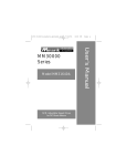
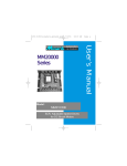
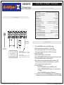
GS23201C
Q U I C K
SCR, Adjustable Speed
Drive for DC Brush Motors
2
3
4
5
6
AC Line Voltage
115 VAC or 230 VAC 50/60Hz, single phase
Armature Voltage (115 VAC Input)
0 - 90 VDC
Armature Voltage (230 VAC Input)
0 - 180 VDC
Armature Current
10 1A
Form Factor
1.37 at base speed
HP Rating (90 VDC)
1/8 - 1 HP
HP Rating (180 VDC)
1/4 - 2 HP
50 VDC (F1 to L1); 100 VDC (F1 to F2)
Field Voltage (115 VAC Input)
Field Voltage (230 VAC Input)
100 VDC (F1 to L1); 200 VDC (F1 to F2)
Max. Field Current
1 ADC
Accel. Time Range:
for 0 - 90 VDC Armature Voltage
0.5 -11 seconds
0.5 - 22 seconds
for 0 - 180 VDC Armature Voltage
Decel. Time Range:
for 0 - 90 VDC Armature Voltage
coast to a stop - 13 seconds
for 0 - 180 VDC Armature Voltage
coast to a stop - 25 seconds
Analog Input Voltage Range (signal must be isolated; S1 to S2):
for 0-90 VDC Armature Voltage
0 - 1.4 VDC
for 0-180 VDC Armature Voltage
0 - 2.8 VDC
7
+
115
VAC
1
MOTOR
ARMATURE
230
VAC
MOTOR FIELD
(SHUNT WOUND
MOTORS ONLY)
-
EARTH GROUND
(GREEN SCREW)
NOTE: DO NOT make
any connections to
terminal 7 if using a
permanent magnet motor.
WITH 115 VAC INPUT:
CONNECT TO TERMINAL 1 FOR 50 VOLT FIELD.
CONNECT TO TERMINAL 6 FOR 100 VOLT FIELD.
WITH 230 VAC INPUT:
CONNECT TO TERMINAL 1 FOR 100 VOLT FIELD.
CONNECT TO TERMINAL 6 FOR 200 VOLT FIELD.
© 2009 Applied Industrial Technologies, Inc. All Rights Reserved. C-0209-11-5143
G U I D E
S P E C I F I C A T I O N S
W I R I N G
1
S T A R T
Requires heatsink GS223-0174 when above 5 Amps
S T A R T U P
1. 1. Set the RUN/BRAKE switch to the BRAKE position.
2. Set the speed adjust potentiometer to “0” (full CCW).
3. Set the input switch to either 115 or 230 VAC accordingly.
Set the output switch to either 90 or 180 VDC accordingly.
4. Apply AC line voltage.
5. Set the POWER switch to the ON position.
6. Set the FORWARD/REVERSE switch to the desired direction of rotation.
7. Set the RUN/BRAKE switch to the RUN position.
8. Slowly advance the speed adjust potentiometer clockwise (CW).
The motor slowly accelerates as the potentiometer is turned CW.
Continue until the desired speed is reached.
9. To reverse direction:
a. Set the RUN/BRAKE switch to the BRAKE position
b. Set the FORWARD/REVERSE switch to the desired direction
of rotation
c. Set the RUN/BRAKE switch to the RUN position.
10. To brake the motor, set the RUN/BRAKE switch to the BRAKE position.
To coast the motor to a stop, set the POWER switch to the OFF position.
For a complete user manual visit www.Applied.com/gsmum
C A L I B R A T I O N
MINIMUM SPEED (MIN SPD)
The MIN SPD trimpot establishes the motor speed obtained in response to
the minimum input signal. It is factory set for zero speed.
S E T T I N G S
IR COMPENSATION (IR COMP)
The IR COMP trimpot setting determines the degree to which motor speed
is held constant as the motor load changes. It is factory set for optimum
motor regulation.
To calibrate the MIN SPD pot, apply the minimum signal. Adjust the MIN
SPD trimpot until the motor runs at the desired speed or is just at the
threshold of rotation.
Use the following procedure to recalibrate the IR COMP setting:
1. Set the IR COMP trimpot to minimum (full CCW).
2. Rotate the speed adjust potentiometer until the motor runs at midspeed
without load (for example, 900 RPM for an 1800 RPM motor). A
MAXIMUM SPEED (MAX SPD)
The MAX SPD setting determines the maximum motor speed when the
speed adjust potentiometer, or voltage input signal is set for maximum
forward speed. It is factory set for maximum rated motor speed.
To calibrate MAX SPD:
1. Set the MAX SPD trimpot full CCW.
2. Set the speed adjust potentiometer or voltage input signal for maximum
forward speed.
3. Adjust MAX SPD until the desired maximum forward speed is reached.
handheld tachometer may be used to measure motor speed.
3. Load the motor armature to its full load armature current rating. The
motor should slow down.
W A R N I N G
Do not make any connections, rewire,
install, or disconnect this drive while
power is applied.
Do not change the FORWARD/REVERSE
switch while the motor is running. The
motor must come to a complete stop
before reversing. Changing motor direction
before allowing the motor to completely
stop will cause excessively high current to
flow in the armature circuit, and will
damage the drive and/or motor.
4. While keeping the load on the motor, rotate the IR COMP trimpot until
the motor runs at the speed measured in step 2. If the motor oscillates
(overcompensation), the IR COMP trimpot may be set too high (CW).
Turn the IR COMP trimpot CCW to stabilize the motor.
5. Unload the motor.
ACCELERATION (ACCEL)
The ACCEL setting determines the time the motor takes
to ramp to a higher speed. ACCEL is factory set for the fastest acceleration
Note: Check the MIN SPD and MAX SPD adjustments after recalibrating to
verify that the motor runs at the desired minimum and maximum speed.
TORQUE
The TORQUE setting determines the maximum torque for accelerating and
driving the motor. To calibrate TORQUE, use the following procedure:
1. With the power disconnected from the drive, connect a DC ammeter in
series with the armature.
2. Set the TORQUE trimpot to minimum (full CCW).
3. Set the speed adjust potentiometer or voltage reference signal to
maximum speed (full CW).
4. Carefully lock the motor armature. Be sure that the motor is firmly
mounted.
5. Apply line power. The motor should be stopped.
6. Slowly adjust the TORQUE trimpot CW until the armature current is
150% of motor rated armature current.
time (full CCW).
To set the acceleration time:
1. Set the speed adjust potentiometer full CCW. The motor should run at
minimum speed.
2. Turn the speed adjust potentiometer full CW and measure the time it
takes the motor to go from minimum to maximum speed.
3. If the time measured in step 2 is not the desired acceleration time, turn
the ACCEL trimpot CW for a slower acceleration time, or CCW for a faster
acceleration time. Repeat steps 1 through 3 until the acceleration time is
correct.
DECELERATION (DECEL)
The DECEL setting determines the time the motor takes to ramp to a lower
speed. DECEL is factory set for the fastest deceleration time (full CCW).
7. Turn the speed adjust potentiometer CCW.
8. Remove line power.
9. Remove the stall from the motor.
10. Remove the ammeter in series with the motor armature if it is no
longer needed.
To set the deceleration time:
1. Set the speed adjust potentiometer full CW. The motor should run at
maximum speed.
2. Turn the speed adjust potentiometer full CCW and measure the time it
takes the motor to go from maximum to minimum speed.
3. If the time measured in step 2 is not the desired deceleration time, turn
the DECEL trimpot CW for a slower deceleration time, or CCW for a
faster deceleration time. Repeat steps 1 through 3 until the deceleration
time is correct.
© 2009 Applied Industrial Technologies, Inc. All Rights Reserved. C-0209-11-5143
For a complete user manual visit www.Applied.com/gsmum