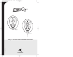
1
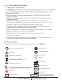
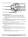
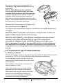
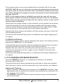
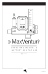
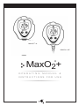
MAXO2®+ A
MAXO2®+ AE
MaxO2+
®
OPERATING
MANUAL
&
INSTRUCTIONS FOR USE
R217M40 Rev. N
Maxtec
2305 South 1070 West
Salt Lake City, Utah 84119
USA
Authorized Representative:
EC REP
TEL (800) 748.5355
FAX (801) 270.5590
email: [email protected]
website: www.maxtec.com
QNET BV
Hommerterweg 286
6436 AM Amstenrade
The Netherlands
CLASSIFICATION
Protection against electric shock: . . . . . . . . . . . . . . . . . . . . . . . . Internally powered equipment.
Protection against water: . . . . . . . . . . . . . . . . . . . . . . . . . . . . . . . . . . . . . . . . . . . . . . . . . . . IPX1
Mode of Operation: . . . . . . . . . . . . . . . . . . . . . . . . . . . . . . . . . . . . . . . . . . . . . . . . . . Continuous
Sterilization: . . . . . . . . . . . . . . . . . . . . . . . . . . . . . . . . . . . . . . . . . . . . . . . . . . . . . See section 7.0
Flammable anesthetic mixture:
Not suitable for use in presence of a
flammable anesthetic mixture
Product Disposal Instructions:
The sensor, batteries, and circuit board are not suitable for regular trash disposal.
Return sensor to Maxtec for proper disposal or dispose according to local guidelines.
Follow local guidelines for disposal of other components.
WARRANTY
The MAXO2+ Analyzer is designed for medical oxygen delivery equipment and systems.
Under normal operating conditions, Maxtec warrants the MAXO2+ Analyzer to be free from
defects of workmanship or materials for a period of 2-years from the date of shipment from
Maxtec, provided that the unit is properly operated and maintained in accordance with
Maxtec’s operating instructions. Based on Maxtec product evaluation, Maxtec’s sole obligation
under the foregoing warranty is limited to making replacements, repairs, or issuing credit for
equipment found to be defective. This warranty extends only to the buyer purchasing the
equipment directly from Maxtec or through Maxtec 's designated distributors and agents as
new equipment.
Maxtec warrants MAXO2+ oxygen sensor in the MAXO2+ Analyzer to be free from defects
in material and workmanship for a period of 2-years from Maxtec’s date of shipment in a
MAXO2+ unit. Should a sensor fail prematurely, the replacement sensor is warranted for the
remainder of the original sensor warranty period.
Routine maintenance items, such as batteries, are excluded from warranty. Maxtec and
any other subsidiaries shall not be liable to the purchaser or other persons for incidental
or consequential damages or equipment that has been subject to abuse, misuse, misapplication, alteration, negligence or accident.
These warranties are exclusive and in lieu of all other warranties, expressed or implied,
including warranty of merchantability and fitness for a particular purpose.
866.4.Maxtecwww.maxtec.com
www.maxtec.com
866.4.Maxtec
www.maxtec.com
I
WARNINGS
!
Indicates a potentially hazardous situation, if not avoided, could result in death or serious injury.
» Never install the sensor in a location that will expose the sensor to patient’s
exhaled breath or secretions, unless you intend to dispose of the sensor, flow
diverter and tee adapter.
» Improper use of this device can cause inaccurate oxygen readings which can lead to
improper treatment, hypoxia or hyperoxia. Follow the procedures outlined in this user manual.
» Not for use in an MRI environment.
» Device specified for dry gas only.
» Never allow an excess length of tubing, lanyard or sensor cable near the patient’s head or neck, which may result in strangulation.
» Before use, all individuals who will be using the MAXO2+ must become thoroughly
familiar with the information contained in this Operation Manual. Strict adherence to the operating
instructions is necessary for safe, effective product performance.
This product will perform only as designed if installed and operated in accordance with the
manufacturer’s operating instructions.
» Use only genuine Maxtec accessories and replacement parts. Failure to do so may seriously
impair the analyzer’s performance. Repair of this equipment must be performed by a qualified
service technician experienced in repair of portable hand held medical equipment.
» Calibrate the MAXO2+ weekly when in operation, or if environmental conditions change
significantly. (ie, Elevation, Temperature, Pressure, Humidity — refer to Section 3.0 of this
manual).
» Use of the MAXO2+ near devices that generate electrical fields may cause erratic readings.
» If the MAXO2+ is ever exposed to liquids (from spills or immersion) or to any other physical abuse,
turn the instrument OFF and then ON. This will allow the unit to go through its self test to assure
everything is operating correctly.
» Never autoclave, immerse or expose the MAXO2+ (including sensor) to high temperatures
(>70°C). Never expose the device to pressure, irradiation vacuum, steam, or chemicals.
» This device does not contain automatic barometric pressure compensation.
» Although the sensor of this device has been tested with various anesthesia gases including nitrous
oxide, Halothane, Isoflurane, Enflurane, Sevoflurane and Desflurane and found to have acceptably
low interference, the device in entirety (including electronics) is not suitable for use in the presence
of a flammable anesthetic mixture with air or with oxygen or nitrous oxide. Only the threaded
sensor face, flow diverter, and “T” adapter may be allowed to contact such a gas mixture.
» NOT for use with inhalation agents. Operating the device in flammable or explosive atmospheres
may result in fire or explosion.
CAUTION:
Indicates a potentially hazardous situation, if not avoided, could result in minor or moderate
injury and property damage.
» Federal Law (USA) restricts this device to sale by or on the order of a physician.
» Replace the batteries with recongnized high quality AA Alkaline or Lithium batteries.
Do NOT use rechargeable batteries.
» If the unit is going to be stored (not in use for 1 month), we recommend that you remove the
batteries to protect the unit from potential battery leakage.
» The Maxtec MAX-250 oxygen sensor is a sealed device containing a mild acid electrolyte, lead
(Pb), and lead acetate. Lead and lead acetate are hazardous waste constituents and should be
disposed of properly, or returned to Maxtec for proper disposal or recovery.
Do not use ethylene oxide sterilization.
Do not immerse the sensor in any cleaning solution, autoclave or expose the sensor to high
temperatures.
» Dropping sensor can adversely affect its performance.
» The device will assume a percent oxygen concentration when calibrating. Be sure to apply 100%
oxygen, or ambient air concentration to the device during calibration or the device will not calibrate
correctly.
Note: This product is latex free.
II
866.4.Maxtecwww.maxtec.com
www.maxtec.com
866.4.Maxtec
www.maxtec.com
TABLE OF CONTENTS
Classification . . . . . . . . . . . . . . . . . . . . . . . . . . . . . . . . . . . . . . . . . . . . . . . . . . . . . . . I
Warranty . . . . . . . . . . . . . . . . . . . . . . . . . . . . . . . . . . . . . . . . . . . . . . . . . . . . . . . . . . I
Warnings . . . . . . . . . . . . . . . . . . . . . . . . . . . . . . . . . . . . . . . . . . . . . . . . . . . . . . . . . II
1.0 SYSTEM OVERVIEW . . . . . . . . . . . . . . . . . . . . . . . . . . . . . . . . . . . . . . . . . . . . 1
1.1 Base Unit Description . . . . . . . . . . . . . . . . . . . . . . . . . . . . . . . . . . . . . . . . . . . 1
1.2 Symbol Guide . . . . . . . . . . . . . . . . . . . . . . . . . . . . . . . . . . . . . . . . . . . . . . . . . 1
1.3 Component Identification . . . . . . . . . . . . . . . . . . . . . . . . . . . . . . . . . . . . . . . . 2
1.4 Component Description . . . . . . . . . . . . . . . . . . . . . . . . . . . . . . . . . . . . . . . . . 2
1.5 MAX-250+ Oxygen Sensor . . . . . . . . . . . . . . . . . . . . . . . . . . . . . . . . . . . . . . 3
2.0 OPERATING INSTRUCTIONS . . . . . . . . . . . . . . . . . . . . . . . . . . . . . . . . . . . . . 3
2.1 Getting Started . . . . . . . . . . . . . . . . . . . . . . . . . . . . . . . . . . . . . . . . . . . . . . . . 3
2.1.1 Protect Tape . . . . . . . . . . . . . . . . . . . . . . . . . . . . . . . . . . . . . . . . . . . . . 3
2.1.2 Automatic Calibration . . . . . . . . . . . . . . . . . . . . . . . . . . . . . . . . . . . . . . 3
2.2 Calibrating the MAXO2+ Oxygen Analyzer . . . . . . . . . . . . . . . . . . . . . . . . . . 4
2.2.1 In-line Calibration (Flow Diverter - Tee Adaptor) . . . . . . . . . . . . . . . . . 4
2.2.2 Direct Flow Calibration (Barb) . . . . . . . . . . . . . . . . . . . . . . . . . . . . . . . 5
3.0 FACTORS INFLUENCING ACCURATE READINGS . . . . . . . . . . . . . . . . . . . . 5
3.1 Elevation Changes . . . . . . . . . . . . . . . . . . . . . . . . . . . . . . . . . . . . . . . . . . . . . 5
3.2 Temperature Effects . . . . . . . . . . . . . . . . . . . . . . . . . . . . . . . . . . . . . . . . . . . . 5
3.3 Pressure Effects . . . . . . . . . . . . . . . . . . . . . . . . . . . . . . . . . . . . . . . . . . . . . . . 6
3.4 Humidity Effects . . . . . . . . . . . . . . . . . . . . . . . . . . . . . . . . . . . . . . . . . . . . . . . 6
4.0 CALIBRATION ERRORS AND ERROR CODES . . . . . . . . . . . . . . . . . . . . . . . 6
5.0 CHANGING THE BATTERIES . . . . . . . . . . . . . . . . . . . . . . . . . . . . . . . . . . . . . 7
6.0 CHANGING THE OXYGEN SENSOR . . . . . . . . . . . . . . . . . . . . . . . . . . . . . . . . 8
6.1 MAXO2+A Model . . . . . . . . . . . . . . . . . . . . . . . . . . . . . . . . . . . . . . . . . . . . . . 8
6.2 MAXO2+AE Model . . . . . . . . . . . . . . . . . . . . . . . . . . . . . . . . . . . . . . . . . . . . . 9
7.0 CLEANING AND MAINTENANCE . . . . . . . . . . . . . . . . . . . . . . . . . . . . . . . . . . 9
8.0 SPECIFICATIONS . . . . . . . . . . . . . . . . . . . . . . . . . . . . . . . . . . . . . . . . . . . . . . 10
8.1 Base Unit Specifications . . . . . . . . . . . . . . . . . . . . . . . . . . . . . . . . . . . . . . . . 10
8.2 Sensor Specifications . . . . . . . . . . . . . . . . . . . . . . . . . . . . . . . . . . . . . . . . . . . 11
9.0 MAXO2+ SPARE PARTS AND ACCESSORIES . . . . . . . . . . . . . . . . . . . . . . . 11
9.1 Included with your Unit . . . . . . . . . . . . . . . . . . . . . . . . . . . . . . . . . . . . . . . . . . 11
9.2 Standard Replacement Parts . . . . . . . . . . . . . . . . . . . . . . . . . . . . . . . . . . . . . 11
9.3 Optional Accessories . . . . . . . . . . . . . . . . . . . . . . . . . . . . . . . . . . . . . . . . . . 12
3.1 Optional Adaptors . . . . . . . . . . . . . . . . . . . . . . . . . . . . . . . . . . . . . . . . . 12
3.2 Mounting Options . . . . . . . . . . . . . . . . . . . . . . . . . . . . . . . . . . . . . . . . . 12
3.3 Carrying Options . . . . . . . . . . . . . . . . . . . . . . . . . . . . . . . . . . . . . . . . . . 12
866.4.Maxtec
www.maxtec.com
866.4.Maxtec
www.maxtec.com
www.maxtec.com
III
1.0 SYSTEM OVERVIEW
1.1 Base Unit Description
The MAXO2+ analyzer provides unparalleled performance and reliability
due to an advanced design that includes the following features and
operational benefits.
» Extra-life oxygen sensor of approximately 1,500,000 O2 percent hours
(2-year warranty).
»D
urable, compact design that permits comfortable, hand-held operation
and easy to clean.
» Operation using only two AA Alkaline batteries (2 x 1.5 Volts) for
approximately 5000 hours of performance with continuous use. For extra
extended long life, two AA Lithium batteries may be used.
» Oxygen-specific, galvanic sensor that achieves 90% of final value in
approximately 15 seconds at room temperature. » Large, easy-to-read, 3 1/2-digit LCD display for readings in the 0-100% range.
» Simple operation and easy one-key calibration.
» Self-diagnostic check of analog and microprocessor circuitry.
» Low battery indication.
» Calibration reminder timer that alerts the operator, using a calibration icon
on the LCD display, to perform a unit calibration.
1.2 Symbol Guide
The following symbols and safety labels are found on the MAXO2+:
!
Follow instructions for use.
On/off Button
Warning
Calibration Button
BAT
Meets ETL standards
%
Do not throw away. Follow local
guidelines for disposal.
CAL
SN
Federal Law (USA) restricts this device to
sale by or on the order of a physician
Do Not
REF
Catalog Number
Percent
Manufacturer
Calibration required
only
Low Battery
Serial Number
LOT
Lot code/Batch code
IPx1
Drip Proof
EC REP
Authorized Representative
in the European Community
866.4.Maxtecwww.maxtec.com
www.maxtec.com
866.4.Maxtec
www.maxtec.com
1
1.3 Component Identification
1
2
LCD Display
3
4
Keypad
5
6
Sample Inlet Connection
FIGURE 1
1.4 Component Description
1
3 1/2-Digit Display - The 3 1/2 digit liquid crystal display (LCD)
provides direct readout of oxygen concentrations in the range of
0 – 105.0% (100.1% to 105.0% used for calibration determination
purposes). The digits also display error codes and calibration codes
as necessary.
2
Low Battery Indicator - The low battery indicator is located at the top
of the display and is only activated when the voltage on the batteries
is below a normal operating level.
3
“%” symbol - The “%” sign is located to the right of the concentration
number and is present during normal operation.
4
Calibration symbol The calibration symbol is located at the
bottom of the display and is timed to activate when a calibration is
necessary.
5
ON/OFF Key -
6
Calibration Key - This key is used to calibrate the device. Holding
the key for more than three seconds will force the device to enter a
calibration mode.
CAL
This key is used to turn the device on or off.
Sample Inlet Connection - This is the port at which the device is
connected to determine oxygen concentration.
2
866.4.Maxtec
www.maxtec.com
866.4.Maxtecwww.maxtec.com
www.maxtec.com
1.5 MAX-250 Oxygen Sensor
The MAX-250+ oxygen sensor offers stability and extra life. The MAX250+ is a galvanic, partial pressure sensor that is specific to oxygen. It
consists of two electrodes (a cathode and an anode), a teflon membrane
and an electrolyte. Oxygen diffuses through the teflon membrane and
immediately reacts at a gold cathode. Concurrently, oxidation occurs
electrochemically at the lead anode, generating an electrical current and
providing a voltage output. Electrodes are immersed in a unique gelled
weak acid electrolyte which is responsible for the sensors long life and
motion insensitive characteristis. Since the sensor is specific to oxygen,
the current generated is proportional to the amount of oxygen present in
the sample gas. When no oxygen is present, there is no electrochemical
reaction and therefore, negligible current is produced. In this sense, the
sensor is self-zeroing.
2.0 OPERATING INSTRUCTIONS
2.1 Getting Started
2.1.1 Protect Tape
Prior to turning on the unit, a protective film covering the threaded
sensor face must be removed. After removing the film, wait
approximately 20 minutes for the sensor to reach equilibrium.
2.1.2 Automatic Calibration
After the unit is turned on it will automatically calibrate to room air. The
display should be stable and reading 20.9%.
CAUTION: The device will assume a percent oxygen concentration
when calibrating. Be sure to supply 100% oxygen, or ambient air
concentration to the device during calibration or the device will not
calibrate correctly.
To check the oxygen concentration of a sample
gas: (after the unit has been calibrated)
1. Connect the Tygon tubing to the bottom of the
analyzer by threading the barbed adapter onto the
oxygen sensor. (figure 2, B)
2. Attach the other end of the sample hose to the
sample gas source and initiate flow of the sample
to the unit at a rate of 1-10 liters per minute (2
liters per minute is recommended).
3. Using the “ON/OFF” key, make sure the unit
is in the power “ON” mode.
4. Allow the oxygen reading to stabilize. This will
normally take about 30 seconds or more.
866.4.Maxtec
www.maxtec.com
866.4.Maxtec
www.maxtec.com
www.maxtec.com
3
2.2 Calibrating the MAXO2+ Oxygen Analyzer
NOTE: We recommend use of medical grade oxygen at 100% when
calibrating the MAXO2+.
The MAXO2+ Analyzer should be calibrated upon initial power-up.
Thereafter, Maxtec recommends calibration on a weekly basis. To serve
as a reminder, a one week timer is started with each new calibration. At
the end of one week a reminder icon “
” will appear on the bottom of
the LCD. Calibration is recommended if the user is unsure when the last
calibration procedure was performed, or if the measurement value is in
question. Start calibration by pressing the key for more than 3 seconds.
The MAXO2+ will automatically detect if you are calibrating with 100%
oxygen or 20.9% oxygen (normal air).
CAL
Do not attempt to calibrate to any other concentration.
For hospital and home care a new calibration is required when
» The measured O2 percentage in 100% O2 is below 97.0% O2.
» The measured O2 percentage in 100% O2 is above 103.0% O2.
» The CAL reminder Icon is blinking at the bottom of the LCD.
» If you are unsure about the displayed O2 percentage. (see Factors influencing accurate readings.)
For ID testing, (or optimum accuracy) a new calibration is required when
» The measured O2 percentage in 100% O2 is below 99.0% O2.
» The measured O2 percentage in 100% O2 is above 101.0% O2.
» The CAL reminder Icon is blinking at the bottom of the LCD.
» If you are unsure about the displayed O2 percentage. (see Factors influencing accurate
readings.)
A simple calibration may be made with the sensor open to static ambient
air. For optimum accuracy Maxtec recommends that the Sensor be placed
in a closed loop circuit where gas flow is moving across the sensor in a
controlled manner. Calibrate with the same type of circuit and flow that you
will use in taking your readings.
2.2.1 In Line Calibration (Flow Diverter – Tee Adapter)
1. Attach the diverter to the MAXO2+ by threading it on to the bottom of
the sensor.
2. Insert the MAXO2+ in the center position of the tee adapter. (figure 2, A)
3. Attach an open-ended reservoir to the end of the tee adapter. Then start
the calibration flow of oxygen at two liters per minute.
»Six to 10 inches of corrugated tubing works well as a reservoir. A
calibration oxygen flow to the MAXO2+ of two liters per minute is
recommended to minimize the possibility of obtaining a “false” calibration value.
4. Allow the oxygen to saturate the sensor. Although a stable value is
usually observed within 30 seconds, allow at least two minutes to ensure
that the sensor is completely saturated with the calibration gas.
5. If the MAXO2+ is not already turned on, do so now by pressing the
4
866.4.Maxtecwww.maxtec.com
www.maxtec.com
866.4.Maxtec
www.maxtec.com
analyzer “ON” button.
6. Press the Cal button on the MAXO2+ until you read the word CAL
on the analyzer display.This can take approximately 3 seconds. The
analyzer will now look for a stable sensor signal and a good reading. When
obtained, the analyzer will display the calibration gas on the LCD.
NOTE: Analyzer will read “Cal Err St” if the sample gas has not stabilized.
2.2.2 Direct Flow Calibration (Barb)
1. Attach the Barbed Adapter to the MAXO2+ by threading it on to the
bottom of the sensor.
2. Connect the Tygon tube to the barbed adapter. (figure 2, B)
3. Attach the other end of the clear sampling tube to a source of oxygen
with a known oxygen concentration value. Initiate flow of the calibration gas
to the unit. Two liters per minute is recommended.
4. Allow the oxygen to saturate the sensor. Although a stable value is
usually observed within 30 seconds, allow at least two minutes to ensure
that the sensor is completely saturated with the calibration gas.
5. If the MAXO2+ is not already turned on, do so now by pressing the
analyzer “ON” button.
6. Press the Cal button on the MAXO2+ until you read the word CAL on
the analyzer display. This can take approximately 3 seconds.
The analyzer will now look for a stable sensor signal and a good reading.
When obtained, the analyzer will display the calibration gas on the LCD.
3.0 FACTORS INFLUENCING ACCURATE READINGS
3.1 Elevation/Pressure Changes
»C
hanges in elevation result in a reading error of approximately 1% of reading
per 250 feet.
» In general, calibration of the instrument should be performed when elevation at
which the product is being used changes by more than 500 feet.
»T
his device does not automatically compensate for changes in barometric
pressure or altitude. If the device is moved to a location of a different altitude, it
must be recalibrated before use.
3.2 Temperature Effects
The MAXO2+ will hold calibration and read correctly within ±3% when at
thermal equilibrium within the operating temperature range. The device
must be thermally stable when calibrated and allowed to thermally stabilize
after experiencing temperature changes before readings are accurate. For
these reasons, the following is recommended:
» For best results, perform the calibration procedure at a temperature close to the
temperature where analysis will occur.
»A
llow adequate time for the sensor to equilibrate to a new ambient temperature.
866.4.Maxtecwww.maxtec.com
www.maxtec.com
866.4.Maxtec
www.maxtec.com
5
CAUTION: “CAL Err St” may result from a sensor that has not reached
thermal equilibrium.
» When used in a breathing circuit, place the sensor upstream of the heater.
3.3 Pressure Effects
Readings from the MAXO2+ are proportional to the partial pressure of
oxygen. The partial pressure is equal to the concentration times the
absolute pressure.
Thus, the readings are proportional to the concentration if the pressure is
held constant. Therefore, the following are recommended:
» Calibrate the MAXO2+ at the same pressure as the sample gas.
» If sample gases flow through tubing, use the same apparatus and flow rates when calibrating as when measuring.
3.4 Humidity Effects
Humidity (non-condensing) has no effect on the performance of the
MAXO2+ other than diluting the gas, as long as there is no condensation.
Depending on the humidity, the gas may be diluted by as much as
4%, which proportionally reduces the oxygen concentration. The
device responds to the actual oxygen concentration rather than the dry
concentration. Environments where condensation may occur are to be
avoided since moisture may obstruct passage of gas to the sensing
surface, resulting in erroneous readings and slower response time. For this
reason, the following is recommended:
» Avoid usage in environments greater than 95% relative humidity.
» When used in a breathing circuit, place the sensor upstream of the
humidifier.
HELPFUL HINT: Dry sensor by lightly shaking moisture out, or flow a dry
gas at two liters per minute across the sensor membrane.
4.0 CALIBRATION ERRORS AND ERROR CODES
The MAXO2+ analyzers have a self test feature built into the software
to detect faulty calibrations, oxygen sensor failures, and low operating
voltage. These are listed below, and include possible actions to take, if an
error code occurs.
E02: No sensor attached
MAXO2+A: Open unit and disconnect and reconnect sensor. Unit should
perform an auto calibration and should read 20.9%. If not, contact Maxtec
Customer Service for possible sensor replacement.
MAXO2+AE: Disconnect and reconnect external sensor. Unit should
perform an auto calibration, and should read 20.9%. If not, contact Maxtec
Customer Service for possible sensor replacement or cable replacement.
6
866.4.Maxtec
www.maxtec.com
866.4.Maxtecwww.maxtec.com
www.maxtec.com
E03: No valid calibration data available
Make sure unit has reached thermal equilibrium. Press and hold the
Calibration Button for three seconds to manually force a new calibration.
E04: Battery below minimum operating voltage
Replace batteries.
CAL Err St: O2 Sensor reading not stable
Wait for displayed oxygen reading to stabilize, when calibrating the device
at 100% oxygen.
Wait for unit to reach thermal equilibrium, (Please note that this can take
up to one half hour, if the device is stored in temperatures outside the
specified operating temperature range).
CAL Err lo: Sensor voltage too low
Press and hold the Calibration Button for three seconds to manually force
a new calibration. If unit repeats this error more than three times, contact
Maxtec Customer Service for possible sensor replacement.
CAL Err hi: Sensor voltage too high
Press and hold the Calibration Button for three seconds to manually force
a new calibration. If unit repeats this error more than three times, contact
Maxtec Customer Service for possible sensor replacement.
CAL Err Bat: Battery voltage too low to recalibrate
Replace batteries.
5.0 CHANGING THE BATTERIES
Batteries should be changed by service personnel.
» Use only brand name batteries.
» Replace with two AA batteries and insert per orientation marked
on the device.
Should the batteries require changing, the device will indicate this in one of
two ways:
» The battery icon on the bottom of the display will begin to flash. This icon
will continue to flash until the batteries are changed. The unit will continue
to function normally for approximately 200 hours.
» If the device detects a very low battery level, an error code of “E04” will
be present on the display, and the unit will not function until the batteries
are changed.
To change the batteries, begin by removing the three screws from the back
of the device. A #1 Phillips screwdriver is required to remove these screws.
Once the screws are removed, gently separate the two halves of the device.
The batteries can now be replaced from the back half of the case.
866.4.Maxtec
www.maxtec.com
866.4.Maxtecwww.maxtec.com
www.maxtec.com
7
Be sure to orient the new batteries as
indicated in the embossed polarity on the
back case.
NOTE: If the batteries are installed
incorrectly the batteries will not make
contact and the device will not operate.
Carefully, bring the two halves of the case
together while positioning the wires so
they are not pinched between the two case
halves. The gasket separating the halves will
be captured on the back case half.
FIGURE 3
Reinsert the three screws and tighten until
the screws are snug. (figure 3).
The device will automatically perform a calibration and begin displaying %
of oxygen.
HELPFUL HINT: If unit does not function, verify that the screws are
tight to allow proper electrical connection.
HELPFUL HINT (MAXO2+ AE): Before closing the two case halves
together, verify that the keyed slot on top of the coiled cable
assembly is engaged on the small tab located on the back case.
This is designed to position the assembly in the correct orientation
and prevent it from rotating. Improper positioning could hinder the
case halves from closing and prevent operation when tightening the
screws.
6.0 CHANGING THE OXYGEN SENSOR
6.1 MAXO2+A Model
Should the oxygen sensor require changing, the device will indicate this by
presenting “Cal Err lo” on the display after initiating a calibration.
To change the oxygen sensor, begin by
removing the three screws from the back
of the device.
A #1 phillips screwdriver is required to
remove these screws.
Once the screws are removed, gently
separate the two halves of the device.
Disconnect the oxygen sensor from the
printed circuit board by pressing the
un-lock lever first and then pulling the
connector out of the receptacle.
8
866.4.Maxtecwww.maxtec.com
www.maxtec.com
866.4.Maxtec
www.maxtec.com
The oxygen sensor can now be replaced from the back half of the case.
HELPFUL HINT: Be sure to orient the new sensor by aligning the red arrow on
the sensor with the arrow in the back case. A small tab is located on the back
case that is designed to engage the sensor and prevent it from rotating within
the case. (figure 4)
NOTE: If the oxygen sensor is installed incorrectly, the case will not come
back together and the unit may be damaged when the screws are reinstalled.
NOTE: If the new sensor has red tape over the outside, remove it, then wait 30
minutes before calibrating.
Reconnect the oxygen sensor to the connector on the printed circuit board.
Carefully bring the two halves of the case together while positioning the
wires to ensure they are not pinched between the two case halves. Make
sure the sensor is fully inserted and in the proper orientation.
Reinsert the three screws and tighten until the screws are snug. Verify the
unit operates properly.
The device will automatically perform a calibration and begin displaying %
of oxygen.
6.2 MAXO2+AE Model
Should the oxygen sensor require changing, the device will indicate this by
presenting “Cal Err lo” on the display.
Unthread the sensor from the cable by rotating the thumbscrew connector
counterclockwise and pull the sensor from the connection.
Replace the new sensor by inserting the electrical plug from the coiled
cord into the receptacle on the oxygen sensor. Rotate the thumbscrew
clockwise until snug.
The device will automatically perform a calibration and begin displaying %
of oxygen.
7.0 CLEANING AND MAINTENANCE
Store the MAXO2+ analyzer in a temperature similar to its ambient
environment of daily use.
The instruction given below describes the methods to clean and disinfect
the instrument, sensor and its accessories (e.g. flow diverter, tee adapter):
Instrument Cleaning:
»W
hen cleaning or disinfecting the exterior of the MAXO2+ analyzer, take
appropriate care to prevent any solution from entering the instrument. Do
not immerse unit in fluids.
»T
he MAXO2+ analyzer surface may be cleaned using a mild detergent
and a moist cloth.
866.4.Maxtecwww.maxtec.com
www.maxtec.com
866.4.Maxtec
www.maxtec.com
9
» The MAXO2+ analyzer is not intended for steam, ethylene oxide or
radiation sterilization.
Oxygen Sensor:
WARNING: Never install the sensor in a location that will expose the
sensor to patient’s exhaled breath or secretions, unless you intend to
dispose of the sensor, flow diverter and tee adapter after use.
»C
lean exterior surface of the the sensor with a cloth moistened with
isopropyl alcohol (65% alcohol/water solution).
»M
axtec does not recommend use of spray disinfectants because they
can contain salts, which can accumulate in the sensor membrane and
impair readings.
»T
he oxygen sensor is not intended for steam, ethylene oxide or radiation
sterilization.
Accessories
» The flow diverter and tee adapter may be disinfected by washing them
with isopropyl alcohol or Cidex (per manufacturer’s instructions). The
parts must be thoroughly dry before they are reused.
» Sterilizing -The flow diverter and tee adapter may be sterilized using
Cidex, steam or ethylene oxide (per manufacturer’s instructions). Due
to the varying conditions imposed on the materials during sterilization it
is not possible to determine the exact number of times the sterilization
processes can be carried out. Therefore, Maxtec recommends that
operators carefully examine the flow diverter and tee adapter after
sterilization and prior to use to verify that the item is fit for use. The
operator should verify that there are no cracks and the item does not
show any indication of material changes or physical damage that may
compromise its effective use. Both flow diverter and tee adapter should
be free of any chemical residue remaining from the sterilization process.
Because of the variability of the cleaning, disinfecting and sterilizing
processes, Maxtec cannot provide specific sterilization instructions, nor
can the sterility of the item be ensured. Therefore, we highly recommend
referring to the manufacturer’s instructions on the details of method.
8.0 SPECIFICATIONS
8.1 Base Unit Specifications
Measurement Range: . . . . . . . . . . . . . . . . . . . . . . . . . . . . . . . . . . . . . . . . . . . . . . . . . . . 0-100%
Resolution: . . . . . . . . . . . . . . . . . . . . . . . . . . . . . . . . . . . . . . . . . . . . . . . . . . . . . . . . . . . . . 0.1%
Accuracy and Linearity: . . . . . . . . . . . . . . . 1% of full scale at constant temperature, R.H. and
pressure when calibrated at full scale
Total Accuracy: . . . . . . . . . . . . . . . . . . ±3% actual oxygen level over full operating temp range
Response Time: . . . . . . . . . . . . . . . . . 90% of final value in approximately 15 seconds at 23˚C
Warm-up Time: . . . . . . . . . . . . . . . . . . . . . . . . . . . . . . . . . . . . . . . . . . . . . . . . . . . None required
Operating Temperature: . . . . . . . . . . . . . . . . . . . . . . . . . . . . . . . . . . . 15˚C - 40˚C (59˚F - 104˚F)
Storage Temperature: . . . . . . . . . . . . . . . . . . . . . . . . . . . . . . . . . . . . -15˚C - 50˚C (5˚F - 122˚F)
10
866.4.Maxtecwww.maxtec.com
www.maxtec.com
866.4.Maxtec
www.maxtec.com
Atmospheric Pressure: . . . . . . . . . . . . . . . . . . . . . . . . . . . . . . . . . . . . . . . . . . . 800-1013 mBars
Humidity: . . . . . . . . . . . . . . . . . . . . . . . . . . . . . . . . . . . . . . . . . . . . . . . 0-95% (non-condensing)
Power Requirements: . . . . . . . . . . . . . . . . . . . . . . . . . . . 2, AA Alkaline batteries (2 x 1.5 Volts)
Battery Life: . . . . . . . . . . . . . . . . . . . . . . . . . . . . approximately 5000 hours with continuous use
Low Battery Indication: . . . . . . . . . . . . . . . . . . . . . . . . . . . . . . . . . "BAT" icon displayed on LCD
Sensor Type: . . . . . . . . . . . . . . . . . . . . . . . . . . . . . . . Maxtec MAX-250 series galvanic fuel cell
Expected Sensor Life: . . . . . . . . . . . . . . . . . . . . . . . . . > 1,500,000 O2 percent hours minimum
(2-year in typical medical applications)
Dimensions:
A Model Dimensions: . . . . . . . . . . . . . . . . 3.0”(W) x 4.0”(H) x 1.5”(D) [76mm x 102mm x 38mm]
A Weight: . . . . . . . . . . . . . . . . . . . . . . . . . . . . . . . . . . . . . . . . . . . . . . . . . . . . . . . 0.4 lbs. (170g)
AE Model Dimensions: . . . . . . . . . . . . . 3.0”(W) x 36.0”(H) x 1.5”(D) [76mm x 914mm x38mm]
Height includes external cable length (retracted)
AE Weight: . . . . . . . . . . . . . . . . . . . . . . . . . . . . . . . . . . . . . . . . . . . . . . . . . . . . . . 0.6 lbs. (285g)
Drift of Measurement: . . . . . . . . . . . . . . . . . . . . . < +/-1% of full scale at constant temperature,
pressure and humidity
8.2 Sensor Specifications
Type: . . . . . . . . . . . . . . . . . . . . . . . . . . . . . . . . . . . . . . . . . . . . . . Galvanic fuel sensor (0-100%)
Life: . . . . . . . . . . . . . . . . . . . . . . . . . . . . . . . . . . . . . . . . . . . . . . . 2-years in typical applications
9.0 MAXO2+ SPARE PARTS AND ACCESSORIES
9.1 Included With Your Unit
Part Number
Item
R217M40
User’s Guide and Operating
Instructions
A Model AE Model
x
x
RP76P06
Lanyard
x
x
R207P17
Threaded Adapter with Tygon Tubing
x
R110P10-001
Flow Diverter
x
x
RP16P02
Blue Tee Adapter
x
x
R217P35
Dovetail Bracket
x
9.2 Standard Replacement Parts and Accessories
Part Number
Item
A Model AE Model
R125P02-011
MAX-250+ Oxygen Sensor
R125P03-002
MAX-250E Oxygen Sensor
R115P85
MAX-250ESF Oxygen Sensor
R217P08
Gasket
x
x
RP06P25
#4-40 Pan Head Stainless Steel Screw
x
x
R217P16-001
Front Assembly (Includes Board &
LCD)
x
x
R217P11-002
Back Assembly
x
x
R217P24
Coiled Cable Assembly
R217P09-001
Overlay
x
x
x
x
x
866.4.Maxtecwww.maxtec.com
www.maxtec.com
866.4.Maxtec
www.maxtec.com
x
11
9.3 Optional Accessories
9.3.1 Optional Adapters
Part Number RP16P02 R103P90 RP16P12 RP16P05 RP16P10 R207P17 Item
Blue Tee Adapter
Perfusion Tee Adapter
Long-Neck Tee Adapter
Pediatric Tee Adapter
MAX-Quick Connect
Threaded Adapter with Tygon Tubing
9.3.2 Mounting Options (requires dovetail R217P23)
Part Number R206P75 R205P86 R213P31 R100P10 Item
Pole Clamp
Wall Mount
Swivel Mount
Rail Mount
9.3.3 Carrying Options
Part Number R217P22 R213P02 R213P56 R217P32 Item
Belt Clip and Pin
Zipper Carrying Case with Shoulder Strap
Deluxe Carrying Case, Water Tight
Soft Case, Tight Fit Carrying Case
Repair of this equipment must be performed by a qualified service
technician experienced in repair of portable hand held medical equipment.
Equipment in need of repair should be sent to:
Maxtec
Customer Service Department
2305 South 1070 West
Salt Lake City, Ut 84119
(Include RMA number issued by customer service)
12
866.4.Maxtec
www.maxtec.com
866.4.Maxtecwww.maxtec.com
www.maxtec.com